JP6455251B2 - Shift lock mechanism in automatic transmission - Google Patents
Shift lock mechanism in automatic transmission Download PDFInfo
- Publication number
- JP6455251B2 JP6455251B2 JP2015053076A JP2015053076A JP6455251B2 JP 6455251 B2 JP6455251 B2 JP 6455251B2 JP 2015053076 A JP2015053076 A JP 2015053076A JP 2015053076 A JP2015053076 A JP 2015053076A JP 6455251 B2 JP6455251 B2 JP 6455251B2
- Authority
- JP
- Japan
- Prior art keywords
- stopper
- shift lever
- lock mechanism
- automatic transmission
- prohibited
- Prior art date
- Legal status (The legal status is an assumption and is not a legal conclusion. Google has not performed a legal analysis and makes no representation as to the accuracy of the status listed.)
- Active
Links
Images


Description
本発明は、自動変速装置におけるシフトロック機構に関する。 The present invention relates to a shift lock mechanism in an automatic transmission.
車両の自動変速装置には、車両の停車時、ブレーキペダルを踏むという条件が満たされた場合にパーキング位置からのシフトレバーの移動を許容し、上記条件が満たされない場合にパーキング位置からのシフトレバーの移動を規制するシフトロック機構が設けられている。
このようなシフトロック機構として、シフトレバーの移動を許容する許容位置と、シフトレバーの移動を禁止する禁止位置との間で揺動可能なストッパと、ストッパを許容位置と禁止位置との間で揺動させるソレノイドと、ストッパに当接することでストッパを許容位置と禁止位置とに位置決めする位置決め部とを有するものが開示されている(特許文献1参照)。
そして、上記シフトロック機構では、ストッパにゴムからなる緩衝部材を設け、操作部材が緩衝部材を介して位置決め部に当接することで操作部材が位置決め部に当接することで発生する操作音(打音)を抑制するようにしている。
The automatic transmission device for a vehicle allows the shift lever to move from the parking position when the condition that the brake pedal is depressed is satisfied when the vehicle is stopped, and shifts from the parking position when the above condition is not satisfied. A shift lock mechanism is provided for restricting the movement of the motor.
As such a shift lock mechanism, a stopper that can swing between an allowable position that allows the shift lever to move and a prohibited position that prohibits the movement of the shift lever, and a stopper between the allowable position and the prohibited position. One having a solenoid to be swung and a positioning portion for positioning the stopper at an allowable position and a prohibited position by contacting the solenoid is disclosed (see Patent Document 1).
In the shift lock mechanism, the stopper is provided with a buffer member made of rubber, and an operation sound (sounding sound) generated by the operation member coming into contact with the positioning unit by the operation member coming into contact with the positioning unit through the buffer member. ).
しかしながら、上記従来技術では、ストッパとは別体の緩衝部材を設けることから、部品点数が増え、また、ストッパに緩衝部材を組み付けることから組み立て作業が必要となり、部品コスト、作業コストの抑制を図る上で改善の余地がある。
本発明は、上記事情に鑑みなされたものであり、操作音の抑制を図りつつ部品コスト、作業コストの抑制を図る上で有利な自動変速装置におけるシフトロック機構を提供することを目的とする。
However, in the above prior art, since the buffer member separate from the stopper is provided, the number of parts is increased, and since the buffer member is assembled to the stopper, an assembly work is required, thereby suppressing the parts cost and the work cost. There is room for improvement above.
The present invention has been made in view of the above circumstances, and an object of the present invention is to provide a shift lock mechanism in an automatic transmission that is advantageous in suppressing component costs and work costs while suppressing operation sounds.
上記目的を達成するために、請求項1記載の発明は、複数のポジションに移動可能なシフトレバーと、前記シフトレバーの移動を許容する許容位置と、前記シフトレバーの移動を禁止する禁止位置との間で揺動可能なストッパと、前記ストッパを前記許容位置と前記禁止位置との間で揺動させるソレノイドと、前記ストッパを揺動方向で挟んだ箇所に配置され前記ストッパを前記許容位置と前記禁止位置とに位置決めする位置決め部と、前記ストッパに設けられ前記許容位置と前記禁止位置で前記位置決め部に当接するクッション部と、を備え、パーキング位置からのシフトレバーの移動を規制する自動変速装置におけるシフトロック機構であって、前記クッション部は前記ストッパに一体に設けられ、前記クッション部は、前記ストッパから互いに離間する方向に突設され、その延在方向の中間部に屈曲部を有する弾性変形可能な一対の脚片と、前記一対の脚片のうちの一方の脚片の先部に設けられ前記許容位置で前記位置決め部に当接可能な第1当接部と、前記一対の脚片のうちの他方の脚片の先部に設けられ前記禁止位置で前記位置決め部に当接可能な第2当接部とを備えることを特徴とする。
請求項2記載の発明は、前記脚片は、前記屈曲部を介してU字状に延在していることを特徴とする。
請求項3記載の発明は、前記第1当接部および前記第2当接部は、互いに離れた箇所で同一の仮想中心軸を中心として円弧状に延在していることを特徴とする。
In order to achieve the above object, the invention according to claim 1 includes a shift lever that can be moved to a plurality of positions, an allowable position that allows movement of the shift lever, and a prohibited position that prohibits movement of the shift lever. A stopper capable of swinging between, a solenoid for swinging the stopper between the allowable position and the prohibition position, and a stopper sandwiched in the swinging direction. An automatic transmission that includes a positioning portion that is positioned at the prohibited position, and a cushion portion that is provided on the stopper and that is in contact with the positioning portion at the allowable position and the prohibited position, and that restricts movement of the shift lever from the parking position. A shift lock mechanism in the apparatus, wherein the cushion portion is provided integrally with the stopper, and the cushion portion is the stopper. A pair of elastically deformable leg pieces projecting in a direction away from each other and having a bent portion in an intermediate part of the extending direction, and provided at a tip portion of one leg piece of the pair of leg pieces, A first abutting portion capable of abutting on the positioning portion at an allowable position, and a second abutting portion provided on a tip portion of the other leg piece of the pair of leg pieces and capable of abutting on the positioning portion at the prohibited position. And a contact portion.
The invention according to claim 2 is characterized in that the leg piece extends in a U shape via the bent portion.
The invention according to claim 3 is characterized in that the first abutting portion and the second abutting portion extend in an arc shape around the same virtual central axis at a location apart from each other.
請求項1記載の発明によれば、ソレノイドによりストッパが許容位置または禁止位置に移動され、第1当接部または第2当接部が位置決め部に当接すると、脚片が屈曲部でたわんで衝撃が吸収される。これによって、ストッパが揺動されて位置決め部に当接された際の操作音が抑制される。
しかも、一対の脚片が互いに離間されているため、第1当接部を支持する脚片および第2当接部を支持する脚片がそれぞれ他方の影響を受けずに円滑にたわむことができる。
したがって、クッション部をストッパと一体に形成した簡単な構成で操作音を効率的に抑制することができるので、ストッパと別体のクッション部を設ける場合に比較して、部品点数を削減でき、また、ストッパにクッション部を組み付ける作業が不要となるため、部品コスト、作業コストの抑制を図る上で有利となる。
請求項2記載の発明によれば、脚片がU字状に延在しているので、一対の脚片がそれぞれ円滑にたわむことができ、アームが許容位置と禁止位置に位置する際の衝撃吸収をより効果的に行なうことができ、操作音を抑制する上で有利となる。
請求項3記載の発明によれば、ストッパや位置決め部に製品誤差や組み付け誤差があっても、第1当接部および第2当接部を位置決め部に確実かつ円滑に当接でき、ストッパが揺動されて位置決め部に当接された際の操作音を抑制する上でより有利となる。
According to the first aspect of the present invention, when the stopper is moved to the allowable position or the prohibited position by the solenoid and the first contact portion or the second contact portion contacts the positioning portion, the leg piece bends at the bent portion. Shock is absorbed. Thereby, the operation sound when the stopper is swung and is brought into contact with the positioning portion is suppressed.
Moreover, since the pair of leg pieces are separated from each other, the leg piece supporting the first contact part and the leg piece supporting the second contact part can be smoothly bent without being influenced by the other. .
Therefore, since the operation sound can be efficiently suppressed with a simple structure in which the cushion part is formed integrally with the stopper, the number of parts can be reduced as compared with the case where the cushion part is provided separately from the stopper. Since the work of assembling the cushion portion on the stopper is not necessary, it is advantageous in reducing the component cost and work cost.
According to the second aspect of the present invention, since the leg pieces extend in a U shape, the pair of leg pieces can each bend smoothly, and the impact when the arms are located at the allowable position and the prohibited position. Absorption can be performed more effectively, which is advantageous in suppressing operation sounds.
According to the invention of claim 3, even if there is a product error or assembly error in the stopper or the positioning portion, the first contact portion and the second contact portion can be reliably and smoothly brought into contact with the positioning portion. This is more advantageous in suppressing the operation sound when it is swung and brought into contact with the positioning portion.
以下、本発明の実施の形態について図面を参照して説明する。
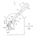
図1は、実施の形態に係る自動変速装置におけるシフトロック機構の構成を示す側面図である。
なお、図中、符号FRは車両の前方を示し、符号RRは車両の後方を示し、符号UPは車両の上方を示し、符号DOWNは車両の下方を示す。
Hereinafter, embodiments of the present invention will be described with reference to the drawings.
FIG. 1 is a side view showing a configuration of a shift lock mechanism in the automatic transmission according to the embodiment.
In the figure, symbol FR indicates the front of the vehicle, symbol RR indicates the rear of the vehicle, symbol UP indicates the upper side of the vehicle, and symbol DOWN indicates the lower side of the vehicle.
自動変速装置10は、ハウジング12と、シフトレバー14と、不図示の自動変速機と、本発明に係るシフトロック機構16とを含んで構成されている。
ハウジング12は車室内に固定されている。
シフトレバー14は、レバー本体18と、ディテントロッド20と、ディテントピン22と、ノブ24と、操作ボタン26とを含んで構成されている。
レバー本体18は、筒状を呈し、その上端が車両前後方向に移動できるように、レバー本体18の下部側がハウジング12に揺動可能に支持されている。本実施の形態では、レバー本体18が支軸38を中心に揺動可能にハウジング12に支持されている。
ディテントロッド20は、レバー本体18の内部にレバー本体18の長手方向に沿って延在し、レバー本体18の長手方向に移動可能に配設されている。ディテントロッド20の下部には、ディテントピン22がディテントロッド20の長手方向と直交する方向に突出形成されている。
レバー本体18の下部には、その長手方向に沿って不図示の長溝が形成され、ディテントロッド20の下部は、長溝を介してレバー本体18の半径方向外側に露出している。
そして、ディテントピン22は、長溝を介してレバー本体18の半径方向外側に、本実施の形態では、車幅方向に突出している。
ディテントピン22は、シフトレバー14がパーキング位置やニュートラル位置等、特定のポジションにある時に、ハウジング12側に設けられたディテント溝40に係合することで、シフトレバー14の揺動を規制して誤操作を防止するためのものである。
ディテントピン22は、ディテントロッド20と共に不図示の付勢部材により上方に付勢され、すなわち、ディテントピン22はディテント溝40に係合する方向に常時付勢されている。
ノブ24は、レバー本体18の上端に設けられ、運転者が把持する部分である。
操作ボタン26は、ノブ24から車幅方向に突出して設けられ、ディテントロッド20に連結されている。
操作ボタン26が押圧されることでディテントロッド20が付勢力に抗して下方に移動されるよう構成されている。
ディテント溝40は、図2(A)に示すようにシフトレバー14の各ポジション、例えばパーキング位置(P)、リバース位置(R)、ニュートラル位置(N)、ドライブ位置(D)、ロー位置(Lo)などといったポジションに対応して複数の段部(溝)が組み合わされて形成されている。そして、例えば、PからR、RからP、NからRなどシフトレバー14を操作するときに操作ボタン26を押圧しなければ、段部にディテントピン22が引っ掛かってシフトレバー14が移動できない仕組みとなっている。
なお、操作ボタン26の押圧が解除されると、ディテントロッド20が付勢力により上方に移動されるので、ディテントピン22は、ディテント溝40の各ポジションに対応した溝に係合される。
自動変速機は、不図示のケーブルを介してレバー本体18に接続され、シフトレバー14が移動されることにより自動変速機のシフト位置が変更される。
そして、自動変速装置10には、シフトレバー14がパーキング位置にあるときに、シフトレバー14の移動を禁止するシフトロック機構16が設けられている。
The
The
The
The
The
A long groove (not shown) is formed in the lower part of the
And the
The
The
The
The
The
As shown in FIG. 2A, the
When the pressing of the
The automatic transmission is connected to the lever
The
シフトロック機構16は、シフトレバー14がパーキング位置にあるときは、パーキング位置から他ポジションへの移動を阻止し、ブレーキペダルが踏み込まれた時のみパーキング位置からのシフトレバー14の移動を許容するよう構成されている。
シフトロック機構16は、図1、図2(A)に示すように、ストッパ30と、位置決め部32と、ソレノイド28と、クッション部34(図3)とを含んで構成されている。
The
As shown in FIGS. 1 and 2A, the
ストッパ30は、ハウジング12に揺動可能に支持され、シフトレバー14の移動を許容する許容位置(図2(C))と、シフトレバー14の移動を禁止する禁止位置(図2(A)、(B))との間で揺動可能に設けられている。
図2(A)、図3、図4に示すように、ストッパ30は合成樹脂製であり、ハウジング12に設けられた支軸36に揺動可能に支持される軸受部3002と、軸受部3002から延びる長尺状のストッパ本体3004と、軸受部3002からストッパ本体3004と反対方向に突設された操作部3006とを備えている。
操作部3006の先端はピン3008を介して後述するソレノイド28に連結され、ソレノイド28の作動に応じて操作部3006が操作されることで、ストッパ30(ストッパ本体3004)が禁止位置と許容位置との間で揺動される。そして、ストッパ30は、シフトレバー14がパーキング位置、つまりディテントピン22が、ディテント溝40のうちパーキング位置(P)に対応するディテント溝部分4001に係合しているときに禁止位置とされ、ディテントピン22の下方側への移動を阻止してシフトレバー14のパーキング位置(P)からの移動を禁止するよう構成されている。
ソレノイド28は、ハウジング12に取着されたソレノイド本体2802と、ストッパ30の操作部3006に連結されてソレノイド本体2802から出没するプランジャ2804とを有している。
プランジャ2804は、通常はソレノイド本体2802から突出する突出位置(図2(A)、(B))とされ、ソレノイド本体2802のコイルに駆動電流が供給されることでソレノイド本体2802に没入する没入位置(図2(C))に引き込まれる。なお、ソレノイド28は、ブレーキペダルの踏み込みにより作動されてプランジャ2804を引き込むよう構成されている。
つまり、ストッパ30は、通常のプランジャ2804が突出された状態で禁止位置とされ、ブレーキペダルが踏み込まれてプランジャ2804が引き込まれた状態で許容位置とされる。
なお、ストッパ30(ストッパ本体3004)の先端には、パーキング位置(P)にあるシフトレバー14のディテントピン22と対向し、ディテントピン22が下方に移動された際にディテントピン22と当接する当接面部3012が設けられている。
これにより、シフレバー14がパーキング位置(P)にあるときには、ストッパ30は、当接面部3012がディテントピン22と対向した状態とされ、ディテントピン22の移動を阻止する。一方、シフレバー14がパーキング位置(P)にある状態でブレーキペダルが踏み込まれるとストッパ30が許容位置に揺動されて、ディテントピン22の下方への移動が許容されてディテント溝部分4001との係合が解除可能、すなわちシフトレバー14のパーキング位置(P)からの移動が可能となる。
The
As shown in FIGS. 2A, 3, and 4, the
The distal end of the
The
The
That is, the
The tip of the stopper 30 (stopper body 3004) is opposed to the
As a result, when the
位置決め部32は、ストッパ30を許容位置と禁止位置とに位置決めするものであり、図2(A)に示すように、ストッパ30をストッパ30の揺動(移動)方向で挟んだ箇所に配置されている。つまり、位置決め部32は、ストッパ30の揺動(移動)方向の両側の位置でハウジング12に設けられた第1当接壁3202と第2当接壁3204とを含んで構成されている。
クッション部34は、ストッパ30に設けられ、ストッパ30の許容位置で第1当接壁3202に当接し、ストッパ30の禁止位置で第2当接壁3204に当接し、これによりストッパ30の許容位置と禁止位置とが位置決めされる。
The positioning
The
図3、図4に示すように、クッション部34は、ストッパ30に一体に設けられ、一対の脚片3404と、第1当接部3406と、第2当接部3408とを備えている。
一対の脚片3404は、ストッパ30から互いに離れる方向に突設され、弾性変形可能であり、ストッパ30の厚さ方向の面と平行する単一の仮想平面上を延在している。
詳細には、ストッパ30からストッパ30の厚さ方向に軸部3402が突設され、軸部3402は、ストッパ30側に位置する大径部3402Aと、大径部3402Aから突出する小径部3402Bとを有している。
一対の脚片3404は、小径部3402Bの先部の半径方向両側からそれぞれ突設され、その延在方向の中間部に弾性変形可能に折り返された屈曲部3410を有しており、軸部3402の半径方向両側で屈曲部3410を介してU字状に延在している。一対の脚片3404は、軸部3402と直交する平面上を延在している。
第1当接部3406は、一対の脚片3404のうちの一方の脚片3404の先部に設けられ、許容位置で第1当接壁3202に当接可能である。
第2当接部3408は、一対の脚片3404のうちの他方の脚片3404の先部に設けられ、禁止位置で第2当接壁3204に当接可能である。
第1当接部3406および第2当接部3408は、軸部3402の半径方向外側で軸部3402を中心とした円弧状に形成されており、円弧状の面がそれぞれ、第1当接壁3202および第2当接壁3204に当接される。
As shown in FIGS. 3 and 4, the
The pair of
Specifically, a
The pair of
The
The
The
次に作用効果について説明する。
図2(A)に示すように、車両の停車時において、シフトレバー14がパーキング位置(P)に位置(ディテントピン22がディテント溝部分4001に係合されている)し、かつ、ブレーキペダルが踏まれていない場合は、ソレノイド28によりプランジャ2804が突出位置に位置し、アーム30は禁止位置に位置しているため、図2(B)に示すように、操作ボタン26が押圧されてディテントロッド20が下方に移動しようとしても、ストッパ30の係止溝部3012にディテントピン22が係止され、ディテントピン22とディテント溝部分4001(パーキング位置(P))との係合が解除されず、シフトレバー14のパーキング位置(P)からの移動が禁止される。
ここで、ブレーキペダルを踏み込むと、ソレノイド28への駆動電流の供給が停止され、プランジャ2804が突出位置から没入位置に移動することによりストッパ30は、図2(A)の禁止位置から図2(C)の許容位置に揺動され、第1当接部3406が第1当接壁3202に当接し、ストッパ30が許容位置に位置決めされる。
したがって、操作ボタン26が押圧されると、ディテントロッド20が下方に移動され、ディテントピン22とディテント溝部分4001(パーキング位置(P))との係合が解除され、シフトレバー14のパーキング位置(P)からの移動が許容される。
この際、クッション部34の第1当接部3406が第1当接壁3202に当接されるが、第1当接部3406側の脚片3404がたわむことにより、第1当接部3406が第1当接壁3202に当接することで生じた衝撃が吸収されることによって操作音が抑制される。
本実施の形態では、脚片3404の延在方向の中間部に屈曲部3410を有しているため、脚片3404のたわみが円滑になされ、衝撃吸収を効果的に行なうことができ、操作音を抑制する上で有利となっている。
Next, the function and effect will be described.
As shown in FIG. 2A, when the vehicle is stopped, the
Here, when the brake pedal is depressed, the supply of drive current to the
Therefore, when the
At this time, the
In the present embodiment, since the
また、図2(C)に示すように、車両の停車時において、シフトレバー14がパーキング位置に位置した状態でブレーキペダルの踏み込みを解除すると、ソレノイド28へ駆動電流が供給され、プランジャ2804が没入位置から突出位置に移動することによりアーム30は、図2(C)の許容位置から図2(A)の禁止位置に揺動され、第2当接部3408が第2当接壁3204に当接し、ストッパ30が禁止位置に位置決めされる。
この際、クッション部34の第2当接部3408が第2当接壁3204に当接されるが、第2当接部3408側の脚片3404がたわむことにより、第2当接部3408が第2当接壁3204に当接することで生じた衝撃が吸収されることによって操作音が抑制される。
この場合も、脚片3404の延在方向の中間部に屈曲部3410を有しているため、脚片3404のたわみが円滑になされ、衝撃吸収を効果的に行なうことができ、操作音を抑制する上で有利となっている。
Further, as shown in FIG. 2C, when the brake pedal is released while the
At this time, the second abutting
Also in this case, since the
したがって、本実施の形態によれば、クッション部34が位置決め部32に当接した際に発生する操作音の抑制を図りつつ、ストッパ30と別体のクッション部34を設ける場合に比較して、部品点数を削減でき、また、ストッパ30にクッション部34を組み付ける作業が不要となるため、部品コスト、作業コストの抑制を図る上で有利となる。
また、本実施の形態では、一対の脚片3404が互いに切り離されているため、第1当接部3406を支持する脚片3404および第2当接部3408を支持する脚片3404がそれぞれ円滑にたわむことができ、ストッパ30が許容位置と禁止位置に位置する際の衝撃吸収を効果的に行なうことができるので、操作音を抑制する上で有利となる。
また、第1当接部3406および第2当接部3408は、軸部3402の半径方向外側で軸部3402を中心とした円弧状に延在し、すなわち、第1当接部3406および第2当接部3408は互いに離れた箇所で同一の仮想中心軸を中心として円弧状に延在している。そのため、ストッパ30に製品誤差や組み付け誤差があっても、あるいは、第1当接壁3202および第2当接壁3204に製品誤差があっても、第1当接部3406および第2当接部3408は第1当接壁3202、第2当接壁3204に確実に円滑に当接でき、操作音を抑制する上でより有利となる。
また、一対の脚片3404は、屈曲部3410を介してU字状に延在しているため、脚片3404のたわみが円滑になされ、衝撃吸収をより効果的に行なうことができるので、操作音を抑制する上でより有利となっている。
Therefore, according to the present embodiment, as compared with the case where the
Further, in this embodiment, since the pair of
Further, the
In addition, since the pair of
10 自動変速装置
12 ハウジング
14 シフトレバー
16 シフトロック機構
28 ソレノイド
30 ストッパ
32 位置決め部
3202 第1当接壁
3204 第2当接壁
3404 一対の脚片
3406 第1当接部
3408 第2当接部
3410 屈曲部
40 ディテント溝
DESCRIPTION OF
Claims (3)
前記シフトレバーの移動を許容する許容位置と、前記シフトレバーの移動を禁止する禁止位置との間で揺動可能なストッパと、
前記ストッパを前記許容位置と前記禁止位置との間で揺動させるソレノイドと、
前記ストッパを揺動方向で挟んだ箇所に配置され前記ストッパを前記許容位置と前記禁止位置とに位置決めする位置決め部と、
前記ストッパに設けられ前記許容位置と前記禁止位置で前記位置決め部に当接するクッション部と、
を備え、パーキング位置からのシフトレバーの移動を規制する自動変速装置におけるシフトロック機構であって、
前記クッション部は前記ストッパに一体に設けられ、
前記クッション部は、前記ストッパから互いに離間する方向に突設され、その延在方向の中間部に屈曲部を有する弾性変形可能な一対の脚片と、前記一対の脚片のうちの一方の脚片の先部に設けられ前記許容位置で前記位置決め部に当接可能な第1当接部と、前記一対の脚片のうちの他方の脚片の先部に設けられ前記禁止位置で前記位置決め部に当接可能な第2当接部と、
を備えることを特徴とする自動変速装置におけるシフトロック機構。 A shift lever that can move to multiple positions;
A stopper that can swing between an allowable position that allows movement of the shift lever and a prohibited position that prohibits movement of the shift lever;
A solenoid that swings the stopper between the allowable position and the prohibited position;
A positioning portion that is disposed at a position sandwiching the stopper in the swinging direction and positions the stopper at the allowable position and the prohibited position;
A cushion portion provided on the stopper and abutting against the positioning portion at the allowable position and the prohibited position;
A shift lock mechanism in an automatic transmission that regulates movement of the shift lever from the parking position,
The cushion portion is provided integrally with the stopper,
The cushion portion protrudes in a direction away from the stopper and has a pair of elastically deformable leg pieces having a bent portion at an intermediate portion in the extending direction, and one leg of the pair of leg pieces. A first abutting portion provided at a tip of one piece and capable of contacting the positioning portion at the permissible position; and a positioning provided at a tip of the other leg piece of the pair of leg pieces at the prohibiting position. A second contact portion capable of contacting the portion;
A shift lock mechanism in an automatic transmission characterized by comprising:
ことを特徴とする請求項1記載の自動変速装置におけるシフトロック機構。 The leg piece extends in a U shape via the bent portion,
The shift lock mechanism in the automatic transmission according to claim 1.
ことを特徴とする請求項1または2記載の自動変速装置におけるシフトロック機構。 The first abutment portion and the second abutment portion extend in a circular arc shape around the same virtual central axis at locations apart from each other,
The shift lock mechanism in the automatic transmission according to claim 1 or 2.
Priority Applications (1)
| Application Number | Priority Date | Filing Date | Title |
|---|---|---|---|
| JP2015053076A JP6455251B2 (en) | 2015-03-17 | 2015-03-17 | Shift lock mechanism in automatic transmission |
Applications Claiming Priority (1)
| Application Number | Priority Date | Filing Date | Title |
|---|---|---|---|
| JP2015053076A JP6455251B2 (en) | 2015-03-17 | 2015-03-17 | Shift lock mechanism in automatic transmission |
Publications (2)
| Publication Number | Publication Date |
|---|---|
| JP2016172482A JP2016172482A (en) | 2016-09-29 |
| JP6455251B2 true JP6455251B2 (en) | 2019-01-23 |
Family
ID=57008707
Family Applications (1)
| Application Number | Title | Priority Date | Filing Date |
|---|---|---|---|
| JP2015053076A Active JP6455251B2 (en) | 2015-03-17 | 2015-03-17 | Shift lock mechanism in automatic transmission |
Country Status (1)
| Country | Link |
|---|---|
| JP (1) | JP6455251B2 (en) |
Family Cites Families (3)
| Publication number | Priority date | Publication date | Assignee | Title |
|---|---|---|---|---|
| JPH068948Y2 (en) * | 1988-07-27 | 1994-03-09 | 豊生ブレーキ工業株式会社 | Parking brake operating device |
| JP3011660B2 (en) * | 1995-06-30 | 2000-02-21 | 小島プレス工業株式会社 | Shift lever device for automatic transmission |
| JP4744712B2 (en) * | 2001-04-04 | 2011-08-10 | 株式会社アツミテック | Automatic transmission operation device |
-
2015
- 2015-03-17 JP JP2015053076A patent/JP6455251B2/en active Active
Also Published As
| Publication number | Publication date |
|---|---|
| JP2016172482A (en) | 2016-09-29 |
Similar Documents
| Publication | Publication Date | Title |
|---|---|---|
| JP6144722B2 (en) | Vehicle shift device | |
| JP6246183B2 (en) | Shift device | |
| JP5142285B2 (en) | Shift lever locking device for vehicles with automatic transmission | |
| JP5225937B2 (en) | Automatic transmission shift device | |
| WO2013038786A1 (en) | Vehicle turn signal switch device | |
| JP5690252B2 (en) | Shift device | |
| JP6455251B2 (en) | Shift lock mechanism in automatic transmission | |
| JP2007146897A (en) | Manual transmission | |
| JP5305676B2 (en) | Shift device with spring device for transmission | |
| JP6129661B2 (en) | Shift device | |
| JP6208494B2 (en) | Accelerator pedal operation device | |
| JP2005297722A (en) | Pedal type parking brake operating device | |
| JP5232727B2 (en) | Automatic transmission shift device | |
| US11002357B2 (en) | Shift device | |
| JP6798767B2 (en) | Accelerator pedal operating device | |
| JP5859385B2 (en) | Shift device | |
| JP2019026156A (en) | Shift lever unit | |
| JP6662693B2 (en) | Shift device | |
| JP4256276B2 (en) | Vehicle direction indication device | |
| JP4726463B2 (en) | Speed change operation device for vehicle | |
| JP7393528B2 (en) | shift device | |
| JP7359644B2 (en) | Range selection mechanism | |
| JP2013173466A (en) | Turn direction indicator | |
| JP2019026155A (en) | Shift lever unit | |
| JP2008279927A (en) | Parking brake device |
Legal Events
| Date | Code | Title | Description |
|---|---|---|---|
| A621 | Written request for application examination |
Free format text: JAPANESE INTERMEDIATE CODE: A621 Effective date: 20180223 |
|
| TRDD | Decision of grant or rejection written | ||
| A977 | Report on retrieval |
Free format text: JAPANESE INTERMEDIATE CODE: A971007 Effective date: 20181115 |
|
| A01 | Written decision to grant a patent or to grant a registration (utility model) |
Free format text: JAPANESE INTERMEDIATE CODE: A01 Effective date: 20181120 |
|
| A61 | First payment of annual fees (during grant procedure) |
Free format text: JAPANESE INTERMEDIATE CODE: A61 Effective date: 20181203 |
|
| R150 | Certificate of patent or registration of utility model |
Ref document number: 6455251 Country of ref document: JP Free format text: JAPANESE INTERMEDIATE CODE: R150 |
|
| S531 | Written request for registration of change of domicile |
Free format text: JAPANESE INTERMEDIATE CODE: R313531 |
|
| R350 | Written notification of registration of transfer |
Free format text: JAPANESE INTERMEDIATE CODE: R350 |