JP2005297722A - Pedal parking brake operation device - Google Patents
Pedal parking brake operation device Download PDFInfo
- Publication number
- JP2005297722A JP2005297722A JP2004115784A JP2004115784A JP2005297722A JP 2005297722 A JP2005297722 A JP 2005297722A JP 2004115784 A JP2004115784 A JP 2004115784A JP 2004115784 A JP2004115784 A JP 2004115784A JP 2005297722 A JP2005297722 A JP 2005297722A
- Authority
- JP
- Japan
- Prior art keywords
- ratchet
- parking brake
- pole
- pedal
- brake pedal
- Prior art date
- Legal status (The legal status is an assumption and is not a legal conclusion. Google has not performed a legal analysis and makes no representation as to the accuracy of the status listed.)
- Granted
Links
Images
Landscapes
- Braking Elements And Transmission Devices (AREA)
Abstract
【課題】ペダル式パーキングブレーキ操作装置のラチェット機構において,パーキングブレーキペダルが後退限に戻るとき,ラチェットポールがポール制御ばねの作用により摺動してガイド孔の内端壁が支軸に激しく衝突しても,衝突音の発生を防ぐようにする。
【解決手段】ラチェットベース2と,これに枢軸4を介して支持されるパーキングブレーキペダル3との間にラチェット機構R設けられ,このラチェット機構Rは,ラチェットベース2に形成される円弧状のラチェットギヤ15と,それと協働すべくパーキングブレーキペダル3に固設される支軸25に支持されるラチェットポール20とを備え,このラチェットポール20には支軸20が摺動及び回転可能に嵌合するガイド孔24が設けられ,パーキングブレーキペダル3が後退限に戻る過程で,支軸25が急激に当接するガイド孔24の内端壁を,合成樹脂製の緩衝壁26で構成すると共に,この緩衝壁26の撓みを許容する緩衝空間27を緩衝壁26に隣接して設けた。
【選択図】 図3
In a ratchet mechanism of a pedal type parking brake operating device, when a parking brake pedal returns to a retreat limit, a ratchet pole slides due to an action of a pole control spring, and an inner end wall of a guide hole collides with a support shaft violently. However, try to prevent the generation of collision noise.
A ratchet mechanism R is provided between a ratchet base 2 and a parking brake pedal 3 supported by the pivot shaft 4. The ratchet mechanism R is an arc-shaped ratchet formed on the ratchet base 2. A gear 15 and a ratchet pole 20 supported by a support shaft 25 fixed to the parking brake pedal 3 to cooperate with the gear 15 are provided. The support shaft 20 is slidably and rotatably fitted to the ratchet pole 20. In the process where the parking brake pedal 3 returns to the retreat limit, the inner end wall of the guide hole 24 with which the support shaft 25 suddenly abuts is constituted by a buffer wall 26 made of synthetic resin. A buffer space 27 that allows the buffer wall 26 to bend is provided adjacent to the buffer wall 26.
[Selection] Figure 3
Description
本発明は,車体に固着されるラチェットベースと,このラチェットベースに枢軸を介して前方踏込み可能に支持されると共に後退方向にばね付勢され,踏込み操作によりパーキングブレーキを作動するパーキングブレーキペダルと,このラチェットベース及びパーキングブレーキペダル間に設けられて,パーキングブレーキペダルを,該ペダルの1回目の踏込み操作により踏み込み位置にロックし,2回目の踏込み操作により上記ロックを解除するラチェット機構とを備える,ペダル式パーキングブレーキ操作装置の改良に関する。 The present invention includes a ratchet base that is fixed to a vehicle body, a parking brake pedal that is supported by the ratchet base via a pivot so as to be able to step forward and is spring-biased in a backward direction, and that activates a parking brake by the stepping operation. A ratchet mechanism, which is provided between the ratchet base and the parking brake pedal, locks the parking brake pedal to the depressed position by the first depression of the pedal, and releases the lock by the second depression. The present invention relates to an improvement of a pedal type parking brake operating device.
かゝるペダル式パーキングブレーキ操作装置において,ラチェット機構は,前記ラチェットベースに形成されて前記枢軸の周方向に沿って隣接する円弧状のラチェットギヤ,収容凹部及びリセットカムと,パーキングブレーキペダルに固設される支軸と,この支軸によりセット位置及びロック解除位置との間を回動可能に支持され,一端部に爪部を有するラチェットポールとを含み,このラチェットポールは,パーキングブレーキペダルが後退限に戻ると前記リセットカムにより前記セット位置に誘導されて前記爪部を前記収容凹部内に収め,パーキングブレーキペダルの踏込み状態では,前記セット位置及びロック解除位置間の中間位置を占めるとき前記爪部を前記ラチェットギヤに係合させるが,前記ロック解除位置に変わると前記爪部を前記ラチェットギヤから離脱させるように構成され,このラチェットポールには,前記支軸に対して回転及び摺動可能に嵌合する長孔状のガイド孔が設けられると共にポール制御ばねが接続され,このポール制御ばねは,パーキングブレーキペダルの2回目の踏込み時に,前記ガイド孔の一端壁を前記支軸に当接させたまゝ前記ラチェットポールを前記ロック解除位置側に付勢し,パーキングブレーキペダルの2回目の踏込み解放に伴ない前記リセットカムが前記ラチェットポールを前記セット位置に誘導するときは前記ガイド孔の他端壁を前記支軸に押圧しながらパーキングブレーキペダルを前記セット位置側に付勢するように構成されるものが,例えば下記特許文献1に開示されるように,既に知られている。
かゝるペダル式パーキングブレーキ操作装置のラチェット機構では,パーキングブレーキの2回目の踏み込み解放により,パーキングブレーキペダルが後退限に戻るとき,ラチェットポールがリセットカムによりセット位置へ誘導され,ポール制御ばねの作用により爪部を収容凹部内に収めるように押圧されることで,ガイド孔の他方の内端壁が支軸に激しく衝突して衝突音を発する。このような異音は,自動車の乗員に多少とも不快感を与えることになる。 In the ratchet mechanism of such a pedal type parking brake operating device, when the parking brake pedal returns to the reverse limit by releasing the parking brake for the second time, the ratchet pole is guided to the set position by the reset cam, and the pole control spring When the claw portion is pressed so as to be accommodated in the housing recess by the action, the other inner end wall of the guide hole collides violently with the support shaft and generates a collision sound. Such abnormal noise can cause some discomfort to the passengers of the car.
ところで,上記特許文献1にも開示されるように,ラチェットポールの表面を緩衝材で被覆することにより,他部材との当接衝撃を緩衝して当接音の発生を抑える技術が知られているが,このような技術をそのまゝ上記ラチェットポールの,支軸の当接部に適用しても,衝撃力が大きいため,満足する消音効果を得るには至らなかった。
By the way, as disclosed in
本発明は,かゝる事情に鑑みてなされたもので,パーキングブレーキの2回目の踏み込み解放により,パーキングブレーキペダルが後退限に戻るとき,ラチェットポールがポール制御ばねの作用により爪部を収容凹部内に収めるように押圧され,ガイド孔の他方の内端壁が支軸に激しく衝突しても,その衝撃力を効果的に緩衝して,衝突音の発生を抑制し得るようにしたラチェット機構を備える,ペダル式パーキングブレーキ操作装置を提供することを目的とする。 The present invention has been made in view of such circumstances, and when the parking brake pedal returns to the retreat limit by releasing the second depression of the parking brake, the ratchet pole accommodates the claw portion by the action of the pole control spring. A ratchet mechanism that is pressed so as to fit inside, and even if the other inner end wall of the guide hole collides violently with the support shaft, the impact force can be effectively buffered to suppress the generation of collision noise. An object of the present invention is to provide a pedal-type parking brake operating device.
上記目的を達成するために,本発明は,車体に固着されるラチェットベースと,このラチェットベースに枢軸を介して前方踏込み可能に支持されると共に後退方向にばね付勢され,踏込み操作によりパーキングブレーキを作動するパーキングブレーキペダルと,このラチェットベース及びパーキングブレーキペダル間に設けられて,パーキングブレーキペダルを,該ペダルの1回目の踏込み操作により踏み込み位置にロックし,2回目の踏込み操作により上記ロックを解除するラチェット機構とを備えてなり,このラチェット機構は,前記ラチェットベースに形成されて前記枢軸の周方向に沿って隣接する円弧状のラチェットギヤ,収容凹部及びリセットカムと,パーキングブレーキペダルに固設される支軸と,この支軸によりセット位置及びロック解除位置との間を回動可能に支持され,一端部に爪部を有するラチェットポールとを含み,このラチェットポールは,パーキングブレーキペダルが後退限に戻ると前記リセットカムにより前記セット位置に誘導されて前記爪部を前記収容凹部内に収め,パーキングブレーキペダルの踏込み状態では,前記セット位置及びロック解除位置間の中間位置を占めるとき前記爪部を前記ラチェットギヤに係合させるが,前記ロック解除位置に変わると前記爪部を前記ラチェットギヤから離脱させるように構成され,このラチェットポールには,前記支軸に対して回転及び摺動可能に嵌合する長孔状のガイド孔が設けられると共にポール制御ばねが接続され,このポール制御ばねは,パーキングブレーキペダルの2回目の踏込み時に,前記ガイド孔の一端壁を前記支軸に当接させたまゝ前記ラチェットポールを前記ロック解除位置側に付勢し,パーキングブレーキペダルの2回目の踏込み解放に伴ない前記リセットカムが前記ラチェットポールを前記セット位置に誘導するときは前記ガイド孔の他端壁を前記支軸に押圧しながらパーキングブレーキペダルを前記セット位置側に付勢するように構成される,ペダル式パーキングブレーキ操作装置において,前記ラチェットポールの前記他側壁を,合成樹脂製の緩衝壁で構成すると共に,この緩衝壁の撓みを許容する緩衝空間を緩衝壁に隣接して設けたことを第1の特徴とする。 In order to achieve the above object, the present invention provides a ratchet base that is fixed to a vehicle body, and is supported by the ratchet base via a pivot so that it can be stepped forward and is spring-biased in the reverse direction. The parking brake pedal is operated between the ratchet base and the parking brake pedal. The parking brake pedal is locked at the depression position by the first depression of the pedal, and the lock is locked by the second depression. A ratchet mechanism for releasing, and this ratchet mechanism is formed on the ratchet base and is fixed to an arcuate ratchet gear, a housing recess and a reset cam, and a parking brake pedal, which are adjacent to each other along the circumferential direction of the pivot shaft. And the set position and A ratchet pawl that is pivotably supported between the unlocked position and has a pawl at one end. The ratchet pawl is guided to the set position by the reset cam when the parking brake pedal returns to the retreat limit. The claw portion is stored in the receiving recess, and when the parking brake pedal is depressed, the claw portion is engaged with the ratchet gear when it occupies an intermediate position between the set position and the unlock position. The claw portion is configured to be disengaged from the ratchet gear when changed to the release position, and the ratchet pole is provided with a long hole-shaped guide hole that is rotatably and slidably fitted to the support shaft. A pole control spring is connected to the guide spring when the parking brake pedal is depressed for the second time. The ratchet pawl is urged toward the unlocking position while one end wall of the hole is in contact with the support shaft, and the reset cam is set to the ratchet pawl when the parking brake pedal is released for the second time. In the pedal type parking brake operating device, wherein the ratchet pole is configured to urge the parking brake pedal toward the set position while pushing the other end wall of the guide hole against the support shaft when guiding to the position. The other side wall is formed of a buffer wall made of synthetic resin, and a buffer space that allows the buffer wall to bend is provided adjacent to the buffer wall.
また本発明は,第1の特徴に加えて,前記支軸を断面円形に形成する一方,前記緩衝壁の前記支軸に対する当接面を平坦に形成したことを第2の特徴とする。 In addition to the first feature, the present invention has a second feature in that the support shaft is formed in a circular cross section, and the contact surface of the buffer wall with respect to the support shaft is formed flat.
さらに本発明は,第1又は第2の特徴に加えて,前記ラチェットポールを金属製とすると共に,このラチェットポールの,前記爪部を除く表面を合成樹脂製の緩衝被膜で被覆し,前記緩衝壁を,これが前記緩衝被膜の,該ラチェットポール両側面を被覆する部分を前記ガイド孔を通して相互に連結するように,該緩衝被膜と一体成形したことを第3の特徴とする。 Furthermore, in addition to the first or second feature, the present invention is configured such that the ratchet pole is made of metal, and the surface of the ratchet pole excluding the claw portion is covered with a buffer film made of a synthetic resin. A third feature is that the wall is integrally formed with the buffer coating so that the portions of the buffer coating covering both sides of the ratchet pole are connected to each other through the guide hole.
本発明の第1の特徴によれば,パーキングブレーキの2回目の踏み込み解放により,パーキングブレーキペダルが後退限に戻るとき,ラチェットポールがリセットカムによりセット位置へ誘導され,ポール制御ばねの作用により爪部を収容凹部内に収めるように押圧されることで,ガイド孔の他方の内端壁が支軸に激しく衝突しても,その他方の内端壁を構成する緩衝壁と,その撓みを許容する緩衝空間との協働により,大なる衝撃力を効果的に吸収して衝突音の発生を防ぐことができる。 According to the first feature of the present invention, when the parking brake pedal returns to the retreat limit by releasing the parking brake for the second time, the ratchet pole is guided to the set position by the reset cam, and the pawl is controlled by the action of the pole control spring. When the other end wall of the guide hole collides with the support shaft violently, the buffer wall that constitutes the other end wall and its deflection are allowed. By cooperating with the buffer space, it is possible to effectively absorb a large impact force and prevent the occurrence of a collision sound.
また本発明の第2の特徴によれば,円形断面の支軸と緩衝壁の平坦面との衝突により,緩衝壁は中央部に集中荷重を受けて,比較的大きな撓みを生じ易く,衝撃力の吸収をより効果的に行うことができ,消音効果を高めることができる。 Further, according to the second feature of the present invention, due to the collision between the support shaft having a circular cross section and the flat surface of the buffer wall, the buffer wall receives a concentrated load at the central portion, and is likely to cause a relatively large deflection, and the impact force. Can be absorbed more effectively, and the silencing effect can be enhanced.
さらに本発明の第3の特徴によれば,金属製のラチェットポールは,爪部を除いて,合成樹脂製の緩衝被膜により表面を被覆されるので,爪部の強度及び耐摩耗性を確保しつゝ,ラチェットポール各部の当接音や摺動音を効果的に抑制することができ,しかも緩衝壁は,緩衝被膜と一体成形されるので,緩衝被膜及び緩衝壁を一挙に成形できて,製造が容易であるのみならず,緩衝壁は,緩衝被膜の,ラチェットポール両側面を被覆する部分をガイド孔を通して相互に連結するので,緩衝被膜のラチェットポール両側面への接合強度を高め,緩衝被膜の剥離を効果的に防ぐことができる。 Furthermore, according to the third feature of the present invention, the surface of the metal ratchet pole is covered with a synthetic resin buffer film except for the claw portion, so that the strength and wear resistance of the claw portion are ensured. In addition, the contact noise and sliding noise of each part of the ratchet pole can be effectively suppressed, and the buffer wall is integrally formed with the buffer film, so that the buffer film and the buffer wall can be formed at once, In addition to being easy to manufacture, the buffer wall connects the portions of the buffer coating covering both sides of the ratchet pole through the guide holes, so that the bonding strength of the buffer coating to both sides of the ratchet pole is increased and the buffer The peeling of the film can be effectively prevented.
本発明の実施の形態を,図面に示す本発明の好適な実施例に基づき以下に説明する。 Embodiments of the present invention will be described below based on preferred embodiments of the present invention shown in the drawings.
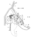
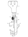
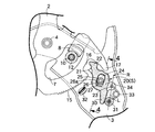
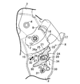
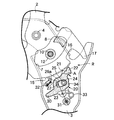
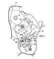
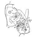
図1は本発明に係る自動車のペダル式パーキングブレーキ操作装置の側面図,図2は図1の2矢視図,図3は図1におけるラチェット機構部を,パーキングブレーキペダルの非操作状態で示す拡大側面図,図4は図3の4−4線拡大断面図,図5はパーキングブレーキペダルの第1回目の踏み込み過程を示す,図3との対応図,図6はパーキングブレーキペダルの第1回目の踏み込み力解放状態(ラチェットポールのロック状態)を示す,図3との対応図,図7はパーキングブレーキペダルの第2回目の踏み込み状態(ラチェットポールロック解除状態)を示す,図3との対応図,図8はパーキングブレーキペダルの第2回目の踏み込み力解放過程(ラチェットポールのリセット過程)を示す,図3との対応図である。
FIG. 1 is a side view of a pedal-type parking brake operating device for an automobile according to the present invention, FIG. 2 is a view taken along
図1及び図2において,自動車の車体Fに固着される複数のブラケット1,1にラチェットベース2が一体に連設され,このラチェットベース2には,下端部に踏み部3aを有するパーキングブレーキペダル3が枢軸4を介して自動車の前後方向に揺動可能に支持される。パーキングブレーキペダル3には,枢軸4を挟んで踏み部3aと反対側に延びる作動アーム3bが形成されており,この作動アーム3bに,図示しない車輪のパーキングブレーキに連なるブレーキワイヤ5がクレビス6を介して接続され,パーキングブレーキペダル3の踏み部3aを前方に踏み込むと,ブレーキワイヤ5を牽引してパーキングブレーキを作動し得るようになっている。
1 and 2, a
ラチェットベース2には,枢軸4を中心とする円弧状の長孔7が形成されると共に,この長孔7の一端部に臨むストッパ片8が取り付けられる。
The
一方,パーキングブレーキペダル3には,その前後揺動に伴ない上記長孔7内を移動するストッパピン10が固設され,このストッパピン10が上記ストッパ片8に当接することにより,パーキングブレーキペダル3の後退限が規制されるようになっている。パーキングブレーキペダル3をその後退限に向かって付勢する戻しばね11がラチェットベース2及びパーキングブレーキペダル3間に張設される。図示例の場合,ストッパピン10の外周面には,ストッパ片8との当接衝撃を吸収する弾性ブッシュ12が嵌め込まれているが,前記ストッパ片8にストッパピン10が当接するクッション部材を付設する場合には,この弾性ブッシュ12を廃止することができる。
On the other hand, the
またラチェットベース2及びパーキングブレーキペダル3間に,該ペダル3を踏み込み位置でロックしたり,そのロックを解除したりするラチェット機構Rが設けられ,このラチェット機構Rを覆うペダルカバー13がパーキングブレーキペダル3の一側面に固着される。
A ratchet mechanism R is provided between the
上記ラチェット機構Rについて,図3〜図8を参照しながら説明する。 The ratchet mechanism R will be described with reference to FIGS.
図3において,ラチェットベース2には,枢軸4を中心とする円弧状のラチェットギヤ15と,このラチェットギヤ15の後側に隣接するU字状の収容凹部16と,この収容凹部16の後側壁から半径方向外方に突出したリセットカム17とが形成され,上記ラチェットギヤ15と協働してパーキングブレーキペダル3を踏み込み位置でロックするラチェットポール20がパーキングブレーキペダル3に取り付けられる。
In FIG. 3, the
このラチェットポール20において,ラチェットギヤ15側の上端部には,前記ラチェットギヤ15に係脱可能な爪部21と,この爪部21に隣接して前記リセットカム17に対向する当接カム22とが設けられ,その下端部にはストッパアーム30が,中間部にはばね係止部23(図示例では小孔)が設けられる。また爪部21とばね係止部23との中間部には,上下方向に長い長孔状のガイド孔24が設けられ,そのガイド孔24に回転及び摺動可能に嵌合する断面円形の支軸25がパーキングブレーキペダル3に固設される。
In the
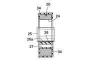
ガイド孔24の特に,下方の内端壁は,エラストマ樹脂等の軟質合成樹脂からなる緩衝壁26で構成されると共に,この緩衝壁26の撓みを許容するように緩衝空間27が緩衝壁26に隣接して設けられる。その際,緩衝壁26の,円形断面の支軸25に対する当接面26aは平坦に形成される。
In particular, the lower inner end wall of the
ラチェットポール20は,支軸25に関してセット位置S(図3参照)とロック解除位置U(図7参照)との間を回動し得る。ラチェットポール20は,そのセット位置Sでは,パーキングブレーキペダル3が後退限に位置するとき爪部21及び当接カム22をラチェットベース2の収容凹部16内に収め,ロック解除位置Uでは,パーキングブレーキペダル3が前方踏み込み位置にあるとき爪部21をラチェットギヤ15から離間させ,またセット位置S及びロック解除位置Uの中間位置(図6参照)では,爪部21をラチェットギヤ15に係合させるようになっている。パーキングブレーキペダル3のセット位置S及びロック解除位置Uは,ストッパアーム30がパーキングブレーキペダル3に固設される第1ストッパ31及び第2ストッパ32に当接することにより規制される。パーキングブレーキペダル3の当接カム22は,リセットカム17に当接したとき,セット位置S側へ姿勢制御されるようになっている。
The
上記第1ストッパ31及びばね係止部23には,捩じりコイルばねからなるポール制御ばね33の両端部がそれぞれ係止され,そのばね力は,ばね係止部23及び第1ストッパ31の両中心を結ぶ直線Lに沿って,ばね係止部23及び第1ストッパ31間を引き離すように働く。したがって,上記直線Lがポール制御ばね33の力の作用線となる。
Both ends of a
図3及び図4に示すように,ラチェットポール20は,金属製,例えば厚肉鋼板製であって,その表面には,爪部21及びばね係止部23周辺部,並びにガイド孔24の金属面を除いて,前記緩衝壁26と同質材の軟質合成樹脂からなる緩衝被膜34が形成される。その際,この緩衝被膜34と前記緩衝壁26とは一体成形される。その結果,緩衝壁26は,緩衝被膜34の,ラチェットポール20の両側面を被覆する部分を相互に連結することになる。
As shown in FIGS. 3 and 4, the
尚,緩衝壁26及び緩衝被膜34の滑り性を高めるために,それを形成するエラストマ樹脂等の軟質合成樹脂に潤滑剤を混合させることは有効である。
In order to improve the slipperiness of the
次に,この実施例の作用について説明する。 Next, the operation of this embodiment will be described.
先ず,図3に示すように,パーキングブレーキペダル3が,ストッパピン10をストッパ片8に当接させた後退限に位置するときは,ポール制御ばね33の力の作用線Lが支軸25の中心の後側を通り,その力がばね係止部23及び第1ストッパ31間を引き離すように働くので,ラチェットポール20は,上方に付勢されて緩衝壁26を支軸25に当接させると共に,この支軸25に関して反時計回りに回動してストッパアーム30を第1ストッパ31に当接させ,ラチェットポール20の爪部21及びストッパアーム30をラチェットベース2の収容凹部16内に収めている。こうしてラチェットポール20は,セット位置Sに保持される。
First, as shown in FIG. 3, when the
いま,踏み部3aを踏み込んで,戻しばね11の付勢力に抗してパーキングブレーキペダル3を前方に回動させると,ブレーキワイヤ5を牽引して,車輪のパーキングブレーキを作動することができる。その際,ラチェットポール20は,パーキングブレーキペダル3の前方への回動に伴ない,爪部21を収容凹部16から脱出させてラチェットギヤ15上を滑らせるが,パーキングブレーキペダル3の前方への回動過程では,ポール制御ばね33の力の作用線Lは,尚も支軸25の右側に位置しているから,ラチェットポール20は,ポール制御ばね33の力によって爪部21をラチェットギヤ15に押しつけるように回動付勢され続ける。
Now, when the stepping
パーキングブレーキの作動後,パーキングブレーキペダル3に対する踏込み力を解放すると,図6に示すように,パーキングブレーキペダル3は戻しばね11の反発力をもって後退方向に回動しようとするため,パーキングブレーキペダル3と一体の支軸25がラチェットポール20のガイド孔24を,緩衝壁26と反対側の内端面を押圧するまで移動して,爪部21をラチェットギヤ15に食い込ませる。すると,支軸25の上記移動に伴ないポール制御ばね33の力の作用線Lが支軸25の中心の前側に移行するので,この作用線Lに沿って,ばね係止部23及び第1ストッパ31間を引き離す方向に作用するポール制御ばね33の力は,爪部21をラチェットギヤ15から離脱させるA方向(図6参照)へラチェットポール20を回動付勢することになるが,爪部21のラチェットギヤ15への食い込み力が強いため,爪部21がラチェットギヤ15から離脱することはない。こうしてパーキングブレーキペダル3は前方踏み込み位置にロックされ,パーキングブレーキの作動状態を保持することができる。
When the depressing force on the
パーキングブレーキの作動を解除するには,再び踏み部3aを踏み込む。それによりパーキングブレーキペダル3が僅かでも前方へ回動すると,支軸25のガイド孔24の内端面への押圧力が解放され,爪部21のラチェットギヤ15への食い込みが弱まるため,ポール制御ばね33によるラチェットポール20の前記A方向への回動付勢により,図7に示すように,ラチェットポール20は,ストッパアーム30を第2ストッパ32に当接させるロック解除位置Uまで回動して,爪部21をラチェットギヤ15から離脱させる。そこで,踏み部3aへの踏み込み力を解放していけば,パーキングブレーキペダル3は,ラチェットポール20をラチェットギヤ15に接触させることなく,戻しばね11の反発力で後退限まで戻ることができる。
In order to cancel the operation of the parking brake, the
その後退過程において,図8に示すように,ラチェットポール20の当接カム22がラチェットベース2のリセットカム17に当接して前方へ押圧されると,ポール制御ばね33の作用線Lが支軸25の中心の後側に移行する。その結果,作用線Lに沿ってばね係止部23及び第1ストッパ31間を引き離す方向に作用するポール制御ばね33の力によって,ラチェットポール20は,ストッパアーム30を第1ストッパ31に当接させる当初のセット位置S(図3参照)に復帰すると同時に,急激に押し上げられるため,ガイド孔24の下端部の緩衝壁26が支軸25に勢いよく衝突するが,緩衝壁26は緩衝空間27側に撓むことで,その衝撃力を効果的に吸収することができ,したがって大きな衝突音の発生を防ぐことができ,ドライバに不快感を与えないで済む。
In the retreating process, as shown in FIG. 8, when the
特に,円形断面の支軸25と緩衝壁26の平坦な当接面26aとの衝突によれば,緩衝壁26は中央部に集中荷重を受けて,撓みを生じ易くなるから,衝撃力の吸収をより効果的に行い,消音効果を高めることができる。
In particular, when the
また金属製のラチェットポール20は,爪部21,ばね係止部23及びガイド孔24内側面を除いて,合成樹脂製の緩衝被膜34により表面を被覆されるので,爪部21,ばね係止部23及びガイド孔24内側面の強度及び耐摩耗性を確保しつゝ,ラチェットポール20が第1,第2ストッパ31,32及びリセットカム17に当接したときの当接音や,ラチェットポール20がパーキングブレーキペダル3側面に対して摺動したときの摺動音を効果的に抑制することができる。
The
しかも前記緩衝壁26は緩衝被膜34と一体成形されるので,緩衝被膜34及び緩衝壁26を一挙に成形できて,製造が容易であるのみならず,緩衝壁26は,緩衝被膜34の,ラチェットポール20両側面を被覆する部分をガイド孔24を通して相互に連結するので,緩衝被膜34のラチェットポール20両側面への接合強度を高め,緩衝被膜34の剥離を効果的に防ぐことができる。
Moreover, since the
本発明は,上記実施例に限定されるものではなく,その要旨を逸脱しない範囲で種々の設計変更が可能である。 The present invention is not limited to the above embodiments, and various design changes can be made without departing from the scope of the invention.
F・・・・・・車体
R・・・・・・ラチェット機構
S・・・・・・ラチェットポールのセット位置
U・・・・・・ラチェットポールのロック解除位置
1・・・・・・ブラケット
2・・・・・・ラチェットベース
3・・・・・・パーキングブレーキペダル
4・・・・・・枢軸
15・・・・・ラチェットギヤ
16・・・・・収容凹部
17・・・・・リセットカム
20・・・・・ラチェットポール
21・・・・・爪部
24・・・・・ガイド孔
25・・・・・支軸
26・・・・・緩衝壁
26a・・・・平坦面
33・・・・・ポール制御ばね
34・・・・・緩衝被膜
F ··· Body R · · · Ratchet mechanism S · · · Ratchet pole set position U · · · Ratchet
Claims (3)
前記ラチェットポール(20)の前記他側壁を,合成樹脂製の緩衝壁(26)で構成すると共に,この緩衝壁(26)の撓みを許容する緩衝空間(27)を緩衝壁(26)に隣接して設けたことを特徴とする,ペダル式パーキングブレーキ操作装置。 A ratchet base (2) fixed to the vehicle body (F), and supported by the ratchet base (2) via a pivot (4) so that it can be stepped forward and spring-biased in the reverse direction. The parking brake pedal (3), which is provided between the ratchet base (2) and the parking brake pedal (3), is operated by the first depression of the pedal (3). And a ratchet mechanism (R) that locks in the depressed position and releases the lock by a second depression operation. The ratchet mechanism (R) is formed on the ratchet base (2) and has the pivot (4 ) Adjacent arcuate ratchet gear (15), receiving recess (16), reset cam (17), and par The support shaft (25) fixed to the brake brake pedal (3) is supported by the support shaft (25) so as to be rotatable between the set position (S) and the unlocking position (U). And a ratchet pole (20) having a pawl portion (21). The ratchet pole (20) is moved to the set position (S) by the reset cam (17) when the parking brake pedal (3) returns to the backward limit. When the parking brake pedal (3) is depressed, the intermediate position between the set position (S) and the unlocking position (U) is set in the receiving recess (16). When occupied, the claw portion (21) is engaged with the ratchet gear (15), but the claw portion (21) is disengaged from the ratchet gear (15) when changed to the unlocking position (U). The ratchet pole (20) is provided with a long hole-shaped guide hole (24) that is rotatably and slidably fitted to the support shaft (25), and a pole control spring (33). The pawl control spring (33) is connected to the ratchet pole while the end wall of the guide hole (24) is in contact with the support shaft (25) when the parking brake pedal (3) is stepped on for the second time. (20) is urged toward the unlocking position (U), and the reset cam (17) moves the ratchet pawl (20) to the set position (with the second release of the parking brake pedal (3)). When guiding to S), the parking brake pedal (3) is urged toward the set position (S) while pressing the other end wall of the guide hole (24) against the support shaft (25). In the pedal type parking brake operating device,
The other side wall of the ratchet pole (20) is composed of a buffer wall (26) made of synthetic resin, and a buffer space (27) allowing the buffer wall (26) to be bent is adjacent to the buffer wall (26). A pedal-type parking brake operating device, characterized in that it is provided.
前記支軸(25)を断面円形に形成する一方,前記緩衝壁(26)の前記支軸(25)に対する当接面(26a)を平坦に形成したことを特徴とする,ペダル式パーキングブレーキ操作装置。 The pedal-type parking brake operating device according to claim 1,
The pedal type parking brake operation characterized in that the support shaft (25) is formed in a circular cross section, and the contact surface (26a) of the buffer wall (26) with respect to the support shaft (25) is formed flat. apparatus.
前記ラチェットポール(20)を金属製とすると共に,このラチェットポール(20)の,前記爪部(21)を除く表面を合成樹脂製の緩衝被膜(34)で被覆し,前記緩衝壁(26)を,これが前記緩衝被膜(34)の,該ラチェットポール(20)両側面を被覆する部分を前記ガイド孔(24)を通して相互に連結するように,該緩衝被膜(34)と一体成形したことを特徴とする,ペダル式パーキングブレーキ操作装置。
In the pedal type parking brake operating device according to claim 1 or 2,
The ratchet pole (20) is made of metal, and the surface of the ratchet pole (20) excluding the claw portion (21) is covered with a synthetic resin buffer film (34), and the buffer wall (26) Is formed integrally with the buffer coating (34) so that the portions of the buffer coating (34) covering both sides of the ratchet pole (20) are connected to each other through the guide hole (24). Features a pedal parking brake operating device.
Priority Applications (1)
| Application Number | Priority Date | Filing Date | Title |
|---|---|---|---|
| JP2004115784A JP4393255B2 (en) | 2004-04-09 | 2004-04-09 | Pedal parking brake operation device |
Applications Claiming Priority (1)
| Application Number | Priority Date | Filing Date | Title |
|---|---|---|---|
| JP2004115784A JP4393255B2 (en) | 2004-04-09 | 2004-04-09 | Pedal parking brake operation device |
Publications (2)
| Publication Number | Publication Date |
|---|---|
| JP2005297722A true JP2005297722A (en) | 2005-10-27 |
| JP4393255B2 JP4393255B2 (en) | 2010-01-06 |
Family
ID=35329798
Family Applications (1)
| Application Number | Title | Priority Date | Filing Date |
|---|---|---|---|
| JP2004115784A Expired - Fee Related JP4393255B2 (en) | 2004-04-09 | 2004-04-09 | Pedal parking brake operation device |
Country Status (1)
| Country | Link |
|---|---|
| JP (1) | JP4393255B2 (en) |
Cited By (10)
| Publication number | Priority date | Publication date | Assignee | Title |
|---|---|---|---|---|
| US7353730B2 (en) * | 2004-08-24 | 2008-04-08 | Honda Motor Co., Ltd. | Foot depressing parking brake apparatus |
| JP2008279927A (en) * | 2007-05-11 | 2008-11-20 | Berusonika:Kk | Parking brake device |
| JP2009101767A (en) * | 2007-10-22 | 2009-05-14 | Otsuka Koki Co Ltd | Parking brake device |
| JP2011505293A (en) * | 2007-12-05 | 2011-02-24 | エドゥシャ エンジニアリング ゲーエムベーハー | Automotive parking brake |
| JP2015157633A (en) * | 2015-06-09 | 2015-09-03 | 株式会社エンプラス | Fitting part structure of vehicle sensor for seat belt retractor |
| JP2015196484A (en) * | 2014-04-02 | 2015-11-09 | 豊田鉄工株式会社 | Parking brake device |
| JP2017030702A (en) * | 2015-08-06 | 2017-02-09 | 豊田鉄工株式会社 | Foot-operated parking brake operation device |
| KR20220091370A (en) * | 2020-12-23 | 2022-06-30 | 황성종 | Regenerative braking control system controllable by foot of driver |
| WO2022139201A3 (en) * | 2020-12-23 | 2022-08-18 | 황성종 | Regenerative braking control system that is controllable by driver's foot |
| CN115009240A (en) * | 2022-07-06 | 2022-09-06 | 杭州禾美汽车科技有限公司 | Brake control system for new energy automobile |
-
2004
- 2004-04-09 JP JP2004115784A patent/JP4393255B2/en not_active Expired - Fee Related
Cited By (13)
| Publication number | Priority date | Publication date | Assignee | Title |
|---|---|---|---|---|
| US7353730B2 (en) * | 2004-08-24 | 2008-04-08 | Honda Motor Co., Ltd. | Foot depressing parking brake apparatus |
| JP2008279927A (en) * | 2007-05-11 | 2008-11-20 | Berusonika:Kk | Parking brake device |
| JP2009101767A (en) * | 2007-10-22 | 2009-05-14 | Otsuka Koki Co Ltd | Parking brake device |
| JP2011505293A (en) * | 2007-12-05 | 2011-02-24 | エドゥシャ エンジニアリング ゲーエムベーハー | Automotive parking brake |
| US8839691B2 (en) | 2007-12-05 | 2014-09-23 | Edscha Engineering Gmbh | Motor vehicle parking brake |
| JP2015196484A (en) * | 2014-04-02 | 2015-11-09 | 豊田鉄工株式会社 | Parking brake device |
| JP2015157633A (en) * | 2015-06-09 | 2015-09-03 | 株式会社エンプラス | Fitting part structure of vehicle sensor for seat belt retractor |
| JP2017030702A (en) * | 2015-08-06 | 2017-02-09 | 豊田鉄工株式会社 | Foot-operated parking brake operation device |
| KR20220091370A (en) * | 2020-12-23 | 2022-06-30 | 황성종 | Regenerative braking control system controllable by foot of driver |
| WO2022139201A3 (en) * | 2020-12-23 | 2022-08-18 | 황성종 | Regenerative braking control system that is controllable by driver's foot |
| KR102475607B1 (en) * | 2020-12-23 | 2022-12-08 | 황성종 | Regenerative braking control system controllable by foot of driver |
| CN115009240A (en) * | 2022-07-06 | 2022-09-06 | 杭州禾美汽车科技有限公司 | Brake control system for new energy automobile |
| CN115009240B (en) * | 2022-07-06 | 2022-12-30 | 杭州禾美汽车科技有限公司 | Brake control system for new energy automobile |
Also Published As
| Publication number | Publication date |
|---|---|
| JP4393255B2 (en) | 2010-01-06 |
Similar Documents
| Publication | Publication Date | Title |
|---|---|---|
| JP2009241919A (en) | Seat sliding device | |
| JP4393255B2 (en) | Pedal parking brake operation device | |
| JP4844063B2 (en) | Foot-operated parking brake device for vehicles | |
| JP2001158335A (en) | Car pedal support structure | |
| EP1752347B1 (en) | Ratchet type parking brake having quiet operation | |
| JP6716524B2 (en) | Vehicle operation pedal device | |
| JP3839285B2 (en) | Parking brake device | |
| US7021174B2 (en) | Parking brake actuator with anti-release feature | |
| WO2009145045A1 (en) | Seat sliding device | |
| JP4234033B2 (en) | Automobile operation pedal device | |
| JP4968204B2 (en) | Brake pedal support structure | |
| JP2967406B2 (en) | Foot-operated parking brake device | |
| US7658126B2 (en) | Safety release feature | |
| JP2011037377A (en) | Brake pedal device for automobile | |
| JP3768420B2 (en) | Parking brake device | |
| JPH0810062Y2 (en) | Parking brake operating device | |
| US8250946B2 (en) | Parking brake for a vehicle | |
| CN211731348U (en) | Parking handle assembly and vehicle | |
| JPH1134824A (en) | Foot-operated parking brake device for vehicles | |
| JP4093998B2 (en) | Parking brake device | |
| JP6421096B2 (en) | Foot-operated parking brake operation device | |
| JP4291045B2 (en) | Parking brake device | |
| JP3902930B2 (en) | Parking brake device | |
| JP4260144B2 (en) | Parking brake device | |
| JPS6122054Y2 (en) |
Legal Events
| Date | Code | Title | Description |
|---|---|---|---|
| A621 | Written request for application examination |
Free format text: JAPANESE INTERMEDIATE CODE: A621 Effective date: 20070215 |
|
| A977 | Report on retrieval |
Free format text: JAPANESE INTERMEDIATE CODE: A971007 Effective date: 20081208 |
|
| A131 | Notification of reasons for refusal |
Free format text: JAPANESE INTERMEDIATE CODE: A131 Effective date: 20090603 |
|
| A521 | Written amendment |
Free format text: JAPANESE INTERMEDIATE CODE: A523 Effective date: 20090731 |
|
| RD03 | Notification of appointment of power of attorney |
Free format text: JAPANESE INTERMEDIATE CODE: A7423 Effective date: 20090731 |
|
| TRDD | Decision of grant or rejection written | ||
| A01 | Written decision to grant a patent or to grant a registration (utility model) |
Free format text: JAPANESE INTERMEDIATE CODE: A01 Effective date: 20090930 |
|
| A01 | Written decision to grant a patent or to grant a registration (utility model) |
Free format text: JAPANESE INTERMEDIATE CODE: A01 |
|
| A61 | First payment of annual fees (during grant procedure) |
Free format text: JAPANESE INTERMEDIATE CODE: A61 Effective date: 20091013 |
|
| R150 | Certificate of patent or registration of utility model |
Free format text: JAPANESE INTERMEDIATE CODE: R150 |
|
| FPAY | Renewal fee payment (event date is renewal date of database) |
Free format text: PAYMENT UNTIL: 20121023 Year of fee payment: 3 |
|
| LAPS | Cancellation because of no payment of annual fees |