JP6453910B2 - Device for emptying a fluid container and method for coupling a fluid container to a corresponding device - Google Patents
Device for emptying a fluid container and method for coupling a fluid container to a corresponding device Download PDFInfo
- Publication number
- JP6453910B2 JP6453910B2 JP2016568109A JP2016568109A JP6453910B2 JP 6453910 B2 JP6453910 B2 JP 6453910B2 JP 2016568109 A JP2016568109 A JP 2016568109A JP 2016568109 A JP2016568109 A JP 2016568109A JP 6453910 B2 JP6453910 B2 JP 6453910B2
- Authority
- JP
- Japan
- Prior art keywords
- fluid
- data
- fluid container
- fluid type
- container
- Prior art date
- Legal status (The legal status is an assumption and is not a legal conclusion. Google has not performed a legal analysis and makes no representation as to the accuracy of the status listed.)
- Active
Links
- 239000012530 fluid Substances 0.000 title claims description 265
- 238000000034 method Methods 0.000 title claims description 27
- 230000008878 coupling Effects 0.000 title description 3
- 238000010168 coupling process Methods 0.000 title description 3
- 238000005859 coupling reaction Methods 0.000 title description 3
- 238000005086 pumping Methods 0.000 claims description 49
- 238000012790 confirmation Methods 0.000 claims description 5
- 238000002372 labelling Methods 0.000 description 6
- 238000001514 detection method Methods 0.000 description 3
- 238000012015 optical character recognition Methods 0.000 description 3
- 150000001875 compounds Chemical class 0.000 description 2
- 239000007788 liquid Substances 0.000 description 2
- 239000000203 mixture Substances 0.000 description 2
- 239000000443 aerosol Substances 0.000 description 1
- 238000004140 cleaning Methods 0.000 description 1
- 238000013500 data storage Methods 0.000 description 1
- 230000001419 dependent effect Effects 0.000 description 1
- 238000001035 drying Methods 0.000 description 1
- 239000000463 material Substances 0.000 description 1
- 238000004659 sterilization and disinfection Methods 0.000 description 1
Images

Classifications
-
- B—PERFORMING OPERATIONS; TRANSPORTING
- B67—OPENING, CLOSING OR CLEANING BOTTLES, JARS OR SIMILAR CONTAINERS; LIQUID HANDLING
- B67D—DISPENSING, DELIVERING OR TRANSFERRING LIQUIDS, NOT OTHERWISE PROVIDED FOR
- B67D7/00—Apparatus or devices for transferring liquids from bulk storage containers or reservoirs into vehicles or into portable containers, e.g. for retail sale purposes
- B67D7/06—Details or accessories
- B67D7/32—Arrangements of safety or warning devices; Means for preventing unauthorised delivery of liquid
- B67D7/34—Means for preventing unauthorised delivery of liquid
- B67D7/344—Means for preventing unauthorised delivery of liquid by checking a correct coupling or coded information
- B67D7/346—Means for preventing unauthorised delivery of liquid by checking a correct coupling or coded information by reading a code
-
- B—PERFORMING OPERATIONS; TRANSPORTING
- B67—OPENING, CLOSING OR CLEANING BOTTLES, JARS OR SIMILAR CONTAINERS; LIQUID HANDLING
- B67D—DISPENSING, DELIVERING OR TRANSFERRING LIQUIDS, NOT OTHERWISE PROVIDED FOR
- B67D7/00—Apparatus or devices for transferring liquids from bulk storage containers or reservoirs into vehicles or into portable containers, e.g. for retail sale purposes
- B67D7/06—Details or accessories
- B67D7/32—Arrangements of safety or warning devices; Means for preventing unauthorised delivery of liquid
- B67D7/3245—Arrangements of safety or warning devices; Means for preventing unauthorised delivery of liquid relating to the transfer method
- B67D7/3272—Arrangements of safety or warning devices; Means for preventing unauthorised delivery of liquid relating to the transfer method using pumps
Description
本発明は、流体容器を空けるための装置であって、流体をポンピングするよう構成されたポンピング装置と、表示装置とを含む、装置に関する。 The present invention relates to a device for emptying a fluid container, comprising a pumping device configured to pump fluid and a display device.
本発明は、上記流体容器を空けるための装置へと流体容器を連結する、対応する方法に更に関する。 The invention further relates to a corresponding method of connecting a fluid container to a device for emptying the fluid container.
上述の流体容器を空けるための装置は、例えば、上記流体容器から流体を送出するための装置として知られている。これらの装置のいくつかは、ポンピング装置に関する更なる情報、例えば回転速度、作業時間等を表示するための表示装置を有する制御モジュールを含む。 An apparatus for opening the above-described fluid container is known as an apparatus for delivering fluid from the fluid container, for example. Some of these devices include a control module having a display device for displaying further information about the pumping device, such as rotational speed, working time, etc.
空の流体容器を交換するとき、新しい流体容器が確実に所望の流体を含むようにすることが必要である。いくつかのシステムにおいて、これは、装置に流体容器を連結するための、流体種類の特定の連結システムによって実現される。これらの種類の連結システムは、様々な理由のために望ましくないことがある。 When replacing an empty fluid container, it is necessary to ensure that the new fluid container contains the desired fluid. In some systems, this is accomplished by a fluid type specific coupling system for coupling the fluid container to the device. These types of connection systems may be undesirable for a variety of reasons.
したがって、本発明の基本的な目的は、新しく連結された流体容器が確実に所望の流体を含むようにする、代替の方法を提供することである。 Accordingly, a basic object of the present invention is to provide an alternative method to ensure that a newly connected fluid container contains the desired fluid.
この目的は、独立請求項に記載の本発明によって達成される。従属クレームは、本発明の有利な実施形態を詳述する。 This object is achieved by the invention as defined in the independent claims. The dependent claims detail advantageous embodiments of the invention.
本発明の様々な側面によれば、流体容器を空けるための装置は、
(i)流体をポンピングするよう構成された、ポンピング装置と;
(ii)表示装置と;
(iii)流体容器の少なくとも一つの標識部材から流体種類識別データを自動的に読み出すよう構成された読み出し装置、並びに/又は上記流体種類識別データを手入力するよう構成された、及び/若しくは表示装置に表示された参照データのリストからこれらの流体種類識別データを選択するよう構成された入力手段を含む、データ入力装置と;
(iv)流体種類識別データと参照データとのデータ比較を行い、流体容器内の流体を識別するよう構成された、識別装置と、を含む。装置は、流体容器内の流体の識別された流体種類に関する流体種類情報を表示装置上に表示するよう構成される。表示された流体種類情報は、ユーザが装置に連結された流体容器によってどの種類の流体が提供されるかを一目で調べることを可能にする。流体種類識別データは、表示流体種類情報の一部であることができる。
According to various aspects of the present invention, an apparatus for emptying a fluid container includes:
(I) a pumping device configured to pump fluid;
(Ii) a display device;
(Iii) a reading device configured to automatically read fluid type identification data from at least one labeling member of the fluid container and / or configured to manually input the fluid type identification data and / or a display device A data input device including input means configured to select these fluid type identification data from a list of reference data displayed on;
(Iv) an identification device configured to perform data comparison between the fluid type identification data and the reference data and identify the fluid in the fluid container. The apparatus is configured to display fluid type information regarding the identified fluid type of the fluid in the fluid container on the display device. The displayed fluid type information allows the user to see at a glance what type of fluid is provided by the fluid container coupled to the device. The fluid type identification data can be part of the display fluid type information.
標識部材は、容器内部の流体、又はより一般的には容器が意図する流体を識別するための流体種類識別データを含む。標識部材は、流体容器の外殻上の標識ラベルであることができる。流体はあらゆる種類の液体、エアロゾル等であることができる。好ましくは、流体は、液体状態の消毒用及び/又は洗浄用の工業的に製造された製品である。 The marking member includes fluid type identification data for identifying the fluid within the container, or more generally the fluid intended by the container. The marking member can be a labeling label on the outer shell of the fluid container. The fluid can be any kind of liquid, aerosol or the like. Preferably, the fluid is an industrially produced product for liquid disinfection and / or cleaning.
本発明の好適な実施例によれば、装置は、空ける工程を開始するために、入力手段を介した手動での確認入力を待つよう構成される。言い換えれば、装置のユーザは、装置の表示装置に表示される流体種類情報を手動で確認しなければならない。 According to a preferred embodiment of the invention, the device is arranged to wait for a manual confirmation input via the input means in order to start the emptying process. In other words, the device user must manually confirm the fluid type information displayed on the display device of the device.
本発明の他の側面によれば、識別装置は、流体種類識別データの現行データ入力と、装置に以前に連結されていた流体容器の流体種類識別データとのデータ比較を行うよう構成される。参照データリストの保存に加えて、装置は、装置に以前に連結されていた流体容器の流体種類識別データを保存する。現在識別された流体種類が、装置に以前に連結されていた流体容器内の流体の流体種類と異なる場合、装置は信号を出すよう好ましくは構成される。 According to another aspect of the invention, the identification device is configured to perform a data comparison between the current data input of the fluid type identification data and the fluid type identification data of a fluid container previously connected to the device. In addition to storing the reference data list, the device stores fluid type identification data for fluid containers previously connected to the device. The device is preferably configured to provide a signal if the currently identified fluid type is different from the fluid type of the fluid in the fluid container previously connected to the device.
他の本発明の好ましい実施形態によれば、読み出し装置は、バーコードスキャナ、又はQRコードスキャナ(QR:クイックレスポンス)、又はOCR(光学式文字認識)用スキャナ、又はRFIDチップリーダー(RFID:無線自動識別)である。流体容器の対応する標識部材は、バーコードラベル、QRコードラベル、又は図形文字ラベル、又はRFIDチップである。 According to another preferred embodiment of the present invention, the reading device is a bar code scanner, a QR code scanner (QR: quick response), an OCR (optical character recognition) scanner, or an RFID chip reader (RFID: wireless). Automatic identification). The corresponding marking member of the fluid container is a bar code label, a QR code label, or a graphic character label, or an RFID chip.
他の本発明の好ましい実施形態によれば、装置は、ポンピング装置を制御するための制御モジュールを更に含み、制御モジュールはデータ処理装置、表示装置、及び/又はデータ入力装置を含む。 According to another preferred embodiment of the invention, the device further comprises a control module for controlling the pumping device, the control module comprising a data processing device, a display device and / or a data input device.
好ましくは、読み出し装置は、有線データ接続及び/又は無線データ接続によって制御装置に連結される。有線データ接続は、例えば、バス接続、特にUSB接続(USB:ユニバーサルシリアルバス)であることができる。無線接続は、例えば、ブルートゥース接続であることができる。 Preferably, the readout device is coupled to the control device by a wired data connection and / or a wireless data connection. The wired data connection can be, for example, a bus connection, in particular a USB connection (USB: Universal Serial Bus). The wireless connection can be, for example, a Bluetooth connection.
本発明の他の側面によれば、データ入力装置、特に読み出し装置は、携帯電話によって提供される。言い換えれば、携帯電話は上記装置のシステムに一体化している。一般に、携帯電話は、とりわけ表示装置と、入力手段を含むデータ入力装置と、カメラとを含む。ほとんどの場合、そのような携帯電話の読み出し装置は、上記携帯電話のカメラである。携帯電話は、好ましくはスマートフォンである。 According to another aspect of the invention, a data input device, in particular a reading device, is provided by a mobile phone. In other words, the mobile phone is integrated into the system of the device. In general, a mobile phone includes, among other things, a display device, a data input device including input means, and a camera. In most cases, such a mobile phone readout device is the mobile phone camera. The mobile phone is preferably a smartphone.
本発明の更に他の好ましい実施例によれば、装置は、流体容器に連結可能であり、流体容器に連結したとき流体容器の充填レベルを測定するよう構成された、センサモジュールを更に含む。装置の表示装置もまた充填レベルを表示するよう構成される。 In accordance with yet another preferred embodiment of the present invention, the apparatus further includes a sensor module that is connectable to the fluid container and configured to measure a fill level of the fluid container when connected to the fluid container. The display of the device is also configured to display the fill level.
本発明の更に他の側面によれば、流体容器を空けるための装置は、ポンピング装置が識別された流体種類に適切かどうか調べるよう構成される。多くの種類のポンピング装置は、上記ポンピング装置内で使用される材料によって、特定の種類の流体のみをポンピングするよう構成されており、他の種類の流体には不適切である。好ましくは、識別装置は、流体種類識別データと、ポンピング装置が適する流体種類のリストからの参照データとのデータ比較を行うよう構成される。 According to yet another aspect of the present invention, an apparatus for emptying a fluid container is configured to check whether a pumping device is appropriate for the identified fluid type. Many types of pumping devices are configured to pump only certain types of fluids, depending on the materials used in the pumping devices, and are not suitable for other types of fluids. Preferably, the identification device is configured to perform a data comparison between the fluid type identification data and reference data from a list of fluid types suitable for the pumping device.
ポンピング装置が識別された流体種類の流体をポンピングするのに適切でない場合、装置はアラーム信号を出すよう好ましくは構成される。 If the pumping device is not suitable for pumping fluid of the identified fluid type, the device is preferably configured to issue an alarm signal.
他の本発明の好ましい実施形態によれば、装置は、ポンピング装置に流体技術的に連結された吸引ランス(suction lance)を更に含む。流体容器に連結された装置の吸引ランスは、上記流体容器内に突出している。 According to another preferred embodiment of the invention, the device further comprises a suction lance fluidically connected to the pumping device. The suction lance of the device connected to the fluid container projects into the fluid container.
本発明は、上記流体容器を空けるための装置に流体容器を連結するための方法に更に関し、方法は:(a)流体容器の少なくとも一つの標識部材から、流体種類識別データの読み出し/読み込みを行う工程と;(b)流体種類識別データと参照データとのデータ比較を行うことによって、流体を識別する工程と;(c)流体容器内の流体の識別された流体種類についての流体種類情報を表示する工程とを含む。表示された流体種類情報は、ユーザが装置に連結された流体容器によってどの種類の流体が提供されるかを一目で調べることを可能にする。 The invention further relates to a method for connecting a fluid container to the device for emptying the fluid container, the method comprising: (a) reading / reading fluid type identification data from at least one labeling member of the fluid container. (B) identifying the fluid by performing a data comparison between the fluid type identification data and the reference data; and (c) fluid type information about the identified fluid type of the fluid in the fluid container. Displaying. The displayed fluid type information allows the user to see at a glance what type of fluid is provided by the fluid container coupled to the device.
本発明の好適な実施例によれば、方法は上記の装置を用いて行われ、(a)読み出し/読み込み工程は、読み出し装置又は入力手段によって行われ;(b)識別工程は、識別装置によって行われ;(c)表示工程は、表示装置によって行われる。 According to a preferred embodiment of the present invention, the method is performed using the above apparatus, (a) the read / read step is performed by a read device or input means; (b) the identification step is performed by an identification device. (C) The display step is performed by a display device.
他の本発明の好ましい実施形態によれば、方法は、表示工程(c)の後に、表示された流体種類情報を確認して、ポンピング工程を開始する更なる工程(d)を含む。 According to another preferred embodiment of the present invention, the method includes a further step (d) of confirming the displayed fluid type information and starting the pumping step after the displaying step (c).
他の本発明の好ましい実施形態によれば、方法は、流体種類識別データの現行データ入力と、上記装置に以前に連結されていた流体容器の流体種類識別データとのデータ比較を行う更なる工程(e)を含む。 According to another preferred embodiment of the present invention, the method further comprises the step of performing a data comparison between the current data input of the fluid type identification data and the fluid type identification data of the fluid container previously connected to the device. (E) is included.
本発明の更に他の好ましい実施例によれば、方法は、ポンピング装置が識別された流体種類をポンピングするのに適切かどうか調べて、ポンピング装置が適切であるときのみ流体をポンピングする更なる工程を含む。 According to yet another preferred embodiment of the present invention, the method further comprises the steps of checking whether the pumping device is suitable for pumping the identified fluid type and pumping the fluid only when the pumping device is appropriate. including.
本発明の目的の更なる詳細、構成、特徴、及び利点は、本発明による分配システムの一実施形態及び例を例示的な態様で示す図面、及びそれぞれの図の以下の記載に開示される。 Further details, configurations, features and advantages of the object of the invention are disclosed in the drawings showing in an exemplary manner one embodiment and example of a distribution system according to the invention and in the following description of each figure.
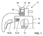
図1は、流体容器10、及び流体容器を空けるための装置12を示しており、装置12は流体容器10の上面に連結されている。容器10は、バーコードラベル16である標識部材14を含む。ラベル16上に印刷されたバーコードは、流体容器10内の流体18、又は少なくとも容器が意図する流体を特徴づける流体種類識別データを含む。装置12は、上記流体容器10から流体を送出するための装置である。上記装置12は、特定の種類の流体18をポンピングするよう構成されたポンピング装置20を含む。より正確には、ポンピング装置20はドーシングポンプ(dosing pump)装置である。装置12は、ポンピング装置20を制御するための制御モジュール21を更に含み、制御モジュール21は、データ処理装置(図示せず)と、保存装置(図示せず)と、表示装置22と、入力手段24を有するデータ入力装置とを含む。例における入力手段24はキーパネルのキーである。これらの入力手段24は、上記流体種類識別データを手入力するよう、及び/又は表示装置22に表示された参照データのリストからこれらの流体種類識別データを選択するよう構成される。装置12は、流体容器の標識部材14から流体種類識別データを直接読み出すよう構成された読み出し装置26を更に含む。示された例の読み出し装置26は、バーコードスキャナ28、より正確には、携帯バーコードスキャナ28である。読み出し装置26は、有線のUSBデータ接続によってポンピング装置20に連結されている。
FIG. 1 shows a
装置12は、制御装置21のデータ処理装置及びデータ記憶デバイス(図示せず)によって提供される識別装置を更に含む。識別装置は、流体種類識別データとリストに掲げられた参照データとのデータ比較を行うよう構成される。制御装置21は、(流体容器10内の流体の)識別された流体種類についての流体種類情報を、表示装置22上に表示するよう構成される。空ける工程を開始するために、装置12は、入力手段24を介した手動での確認入力を待つよう構成される。
The
更に、装置12は、ポンピング装置20が流体容器10に収容された流体をポンピングするのに適切かどうか調べるよう構成される。装置12は、流体容器10内に突出した吸引ランス30を更に含む。
Furthermore, the
(新しい)流体容器10を上記の装置12に連結することは:
−読み出し装置26によって、流体容器10の少なくとも一つの標識部材14から流体種類識別データの自動読み出し及び読み込みを行うこと、又は入力手段24によって、流体容器10の少なくとも一つの標識部材14から流体種類識別データの手入力を行う工程と;
−識別装置を用いて流体種類識別データと参照データとのデータ比較を行うことによって、流体18の流体種類を識別する工程と;
−表示装置22を用いて流体容器10内の流体18の識別された流体種類についての流体種類情報を表示する工程とによって行うことができる。
Connecting the (new)
-Automatic reading and reading of fluid type identification data from at least one labeling member 14 of the
Identifying the fluid type of the fluid 18 by performing a data comparison between the fluid type identification data and the reference data using an identification device;
-Displaying the fluid type information for the identified fluid type of the fluid 18 in the
表示された流体識別情報によって、装置12のユーザは、装置12に連結された流体容器10によってどの種類の流体18が提供されるかを「一目で」調べることができる。
The displayed fluid identification information allows the user of the
表示工程の後の任意の確認工程において、ユーザは、表示された流体識別情報を確認して、ポンピング工程を開始しなければならない。 In an optional confirmation step after the display step, the user must confirm the displayed fluid identification information and begin the pumping step.
任意の比較ステップにおいて、制御装置は、流体種類識別データの現行データ入力と、装置12に以前に連結されていた流体容器10の流体種類識別データとのデータ比較を行う。
In an optional comparison step, the controller performs a data comparison between the current data input of the fluid type identification data and the fluid type identification data of the
任意のチェック工程において、装置10は、ポンピング装置20が識別された流体種類の流体18をポンピングするのに適切か否かを調べる。その後、ポンピング装置20が識別された流体種類に適切であれば、ポンピング工程が自動的に開始される。
In an optional check step, the
図2は、流体容器10とともに、流体容器10に連結された他の流体容器を空ける装置12を示す。図2に示す流体容器10の標識部材14は、QRコードラベル32である。このシステムにおいて、読み出し装置26は、携帯電話34、又はより正確にはスマートフォンによって提供される。言い換えれば、装置12のシステムは、装置12の読み出し装置26を含む携帯電話/スマートフォン34を含む。この場合、読み出し装置26は、上記電話34に含まれるカメラ(図示せず)である。読み出し装置26は、無線ブルートゥースデータ接続によってポンピング装置20に連結されている。
FIG. 2 shows a
いくつかの実施形態において、装置12は、流体容器10に連結したとき流体容器10の充填レベルを測定するよう構成されたセンサモジュール(図示せず)を更に含む。表示装置22は充填レベルを表示するよう構成されており、以下の安全性レベルにつながる。
In some embodiments, the
レベル1−流体種類情報(例えば流体名)によって視覚的に: Level 1-visually by fluid type information (eg fluid name):
・流体容器10及び対応する流体種類情報を設定した後、表示装置22は常に流体種類情報を示す。
After setting the
・「空検出」の後、表示装置22に表示されている流体種類情報に対応する流体種類識別データを含む標識部材14を有する流体容器10(例えばバレル)を、交換しなければならないことをユーザに知らせる。
After the “empty detection”, the user must replace the fluid container 10 (eg, barrel) having the marking member 14 including the fluid type identification data corresponding to the fluid type information displayed on the
・流体容器を交換した後、ユーザは、正しい流体種類に交換されたことを、装置12で確認(流体種類情報/流体種類識別データを視覚的に比較)しなければならない。
After replacing the fluid container, the user must confirm (visually compare the fluid type information / fluid type identification data) with the
レベル2−スマートフォン34及び流体種類識別データ(例えばラベル情報)によって視覚的に: Level 2-Visually via smartphone 34 and fluid type identification data (eg, label information):
流体容器10を設定した後、表示装置22は、対応する流体種類情報を常に示す。
After setting the
・「空検出」の後、表示装置22は、流体種類情報の下に、調整された流体種類に対応するGTIN−13−コード(QR−コード)のような、更なる情報を示す(更なる情報は、pH値、粘度、乾燥、ポンプ内に保存された他の関連するパラメータであってよい。)。
After “empty detection”, the
・流体容器10を交換した後、ユーザは、流体容器10の標識部材の流体種類識別データ(例えばGTIN−13−コード、又はQR−コード)をスキャンしなければならない。
-After replacing the
・次に、ユーザは、ディスプレイに示された流体種類識別データ(例えばGTIN−13−コード、又はQR−コード)をスキャンしなければならない。
スマートフォン上で動作するモバイルアプリケーション(App)は、GTIN−13−コード又はQR−コードの情報を比較して、同一の流体種類について「緑色光」、類似する流体種類について「黄色光」、異なる流体種類について「赤色光」を発する。当然、スキャンの順番はその逆であってもよい。
-Next, the user must scan the fluid type identification data (eg, GTIN-13 code, or QR-code) shown on the display.
The mobile application (App) running on the smartphone compares the information of the GTIN-13 code or QR-code, “green light” for the same fluid type, “yellow light” for similar fluid types, different fluids A “red light” is emitted for the type. Of course, the scanning order may be reversed.
・次に、ユーザは、装置12で流体容器10の交換を手動で確認しなければならない。
レベル2は、スキャンし比較するための充分なソフトウェアを有する設備(すなわちスマートフォン)を要求する。
-Next, the user must manually confirm the replacement of the
Level 2 requires equipment (ie a smartphone) with sufficient software to scan and compare.
レベル3−例えばスキャナのような接続された読み出し装置(26)によって自動的に: Level 3—automatically by a connected reading device (26) such as a scanner:
・流体容器を設定した後、表示装置22は、常に流体種類情報(例えば流体名)を示す。
After the fluid container is set, the
・空検出の後、表示装置は、流体種類情報の下に、ユーザが装置12のUSBポートにスキャナを接続しなければならないというメッセージを示す。
After empty detection, the display device shows a message under the fluid type information that the user must connect the scanner to the USB port of the
・流体容器12を交換した後、ユーザは、カメラで流体容器12のラベルに印刷された標識部材14(例えばGTIN−13−コード、QR−コード)を読み出さなければならない。
After replacing the
・読み出し装置26から装置12までデータを送信した後、装置12のソフトウェアは、流体種類識別データ(GTIN−13−コード、QR−コード)と、参照データのリストからの参照データとを比較して、同一の流体18について緑、類似の流体18について黄色、異なる流体18について赤を発する。
After transmitting data from the reading device 26 to the
緑でない場合、ユーザは、ポンピング装置がスキャンされた流体を扱わなければならないことを、装置で、手動で確認しなければならない。 If not green, the user must manually confirm at the device that the pumping device must handle the scanned fluid.
本明細書、及び添付の特許請求の範囲において用いる、単数形(原文中)「a」、「an」、及び「the」は、別途文脈上明確に述べない限り、複数形の引用を含む点に留意されたい。したがって、例えば、「化合物(a compound)」を含む組成物、との記載は、2以上の化合物の混合物を含む。別途文脈上明確に述べない限り、用語「又は」は、「及び/又は」を含む意味で一般に使用することにも留意されたい。
以下の項目[1]〜[15]に、本発明の実施形態の例を列記する。
[1]
流体容器(10)を空けるための装置(12)であって、前記装置(12)は:
流体をポンピングするよう構成された、ポンピング装置(20)と;
表示装置(22)と;
前記流体容器(10)の少なくとも一つの標識部材(14)から流体種類識別データを読み出すよう構成された、読み出し装置(26)、並びに/又は
前記流体種類識別データを手動で入力するよう、及び/若しくは前記表示装置(22)に表示された参照データのリストから前記流体種類識別データを手動で選択するよう構成された、入力手段(24)を含む、データ入力装置と;
前記流体容器(10)内の流体(18)を識別するため、前記流体種類識別データと前記参照データとのデータ比較を行うよう構成された、識別装置と
を含み、
前記装置(12)は、前記流体容器(10)内の前記流体の識別された流体種類についての流体種類情報を、前記表示装置(22)上に表示するよう構成された、装置。
[2]
前記装置(12)は、空ける工程を開始するために、入力手段(24)を介した手動での確認入力を待つよう構成された、項目1に記載の装置。
[3]
前記識別装置は、流体種類識別データの現行データ入力と、前記装置(12)に以前に連結されていた流体容器(10)の流体種類識別データとのデータ比較を行うよう構成された、項目1又は2に記載の装置。
[4]
前記読み出し装置(26)は、バーコードスキャナ(28)、又はQRコードスキャナ、又はOCR用スキャナ、又はRFIDチップリーダーである、項目1〜3のいずれか一項に記載の装置。
[5]
前記ポンピング装置(20)を制御するための制御モジュール(21)を更に含み、前記制御モジュール(21)は、データ処理装置、前記表示装置(22)、及び/又は前記データ入力装置を含む、項目1〜4のいずれか一項に記載の装置。
[6]
前記データ入力装置、特に前記読み出し装置(26)は、携帯電話(30)によって提供される、項目1〜5のいずれか一項に記載の装置。
[7]
前記流体容器(10)に連結可能であり、前記流体容器(10)に連結されたときに前記流体容器(10)の充填レベルを測定するよう構成されたセンサモジュールを更に含む、項目1〜6のいずれか一項に記載の装置。
[8]
前記装置(12)は、前記ポンピング装置(20)が識別された流体種類に適切かどうか調べるよう構成された、項目1〜7のいずれか一項に記載の装置。
[9]
前記識別装置は、前記流体種類識別データと、前記ポンピング装置(20)に適切である流体種類のリストからの参照データとのデータ比較を行うよう構成された、項目8に記載の装置。
[10]
前記ポンピング装置(20)に流体技術的に連結された吸引ランス(28)を更に含む、項目1〜9のいずれか一項に記載の装置。
[11]
特に項目1〜10のいずれか一項に記載の装置(12)によって、流体容器(10)を空けるための装置(12)に流体容器(10)を連結する方法であって、前記方法は:
前記流体容器(10)の少なくとも一つの標識部材(18)から流体種類識別データの読み出し/読み込みを行う工程と;
流体種類識別データと参照データとのデータ比較を行うことによって流体を識別する工程と;
前記流体容器(10)内の前記流体(18)の識別された流体種類についての流体種類情報を表示する工程と
を含む、方法。
[12]
項目1〜10のいずれか一項に記載の装置(12)を用いて行われ、
前記読み出し/読み込み工程は、前記読み出し装置(26)又は前記入力手段(24)によって行われ;
前記識別工程は、前記識別装置によって行われ;
前記表示工程は、前記表示装置(22)によって行われる、項目11に記載の方法。
[13]
前記表示工程の後に、表示された前記流体識別情報を確認してポンピング工程を開始する工程を更に含む、項目11又は12に記載の方法。
[14]
流体種類識別データの現行データ入力と、前記装置(12)に以前に連結されていた流体容器(10)の流体種類識別データとのデータ比較を行う工程を更に含む、項目11〜13いずれか一項に記載の方法。
[15]
前記ポンピング装置(20)が識別された流体種類をポンピングするのに適切かどうか調べる工程と、
前記ポンピング装置(20)が適切である場合、前記流体(18)をポンピングする工程とを更に含む、項目11〜14のいずれか一項に記載の方法。
As used herein and in the appended claims, the singular forms “a”, “an”, and “the” include plural references unless the context clearly dictates otherwise. Please note that. Thus, for example, reference to a composition containing “a compound” includes a mixture of two or more compounds. It should also be noted that the term “or” is generally used in its sense including “and / or” unless the content clearly dictates otherwise.
Examples of embodiments of the present invention are listed in the following items [1] to [15].
[1]
A device (12) for opening a fluid container (10), said device (12):
A pumping device (20) configured to pump fluid;
A display device (22);
A readout device (26) configured to read fluid type identification data from at least one marking member (14) of the fluid container (10), and / or
Input means (24) configured to manually input the fluid type identification data and / or to manually select the fluid type identification data from a list of reference data displayed on the display device (22). Including a data input device;
An identification device configured to perform data comparison between the fluid type identification data and the reference data to identify the fluid (18) in the fluid container (10);
Including
The device (12) is configured to display fluid type information about the identified fluid type of the fluid in the fluid container (10) on the display device (22).
[2]
Device according to item 1, wherein the device (12) is arranged to wait for a manual confirmation input via the input means (24) in order to start the emptying process.
[3]
Item 1 is configured to perform a data comparison between the current data input of fluid type identification data and the fluid type identification data of a fluid container (10) previously connected to the device (12). Or the apparatus of 2.
[4]
The apparatus according to any one of items 1 to 3, wherein the reading device (26) is a barcode scanner (28), a QR code scanner, an OCR scanner, or an RFID chip reader.
[5]
An item further comprising a control module (21) for controlling the pumping device (20), the control module (21) comprising a data processing device, the display device (22), and / or the data input device. The apparatus as described in any one of 1-4.
[6]
The device according to any one of items 1 to 5, wherein the data input device, in particular the reading device (26), is provided by a mobile phone (30).
[7]
Items 1-6 further comprising a sensor module that is connectable to the fluid container (10) and configured to measure a fill level of the fluid container (10) when connected to the fluid container (10). The apparatus as described in any one of.
[8]
8. Apparatus according to any of items 1-7, wherein the apparatus (12) is configured to check whether the pumping apparatus (20) is appropriate for the identified fluid type.
[9]
9. The apparatus of item 8, wherein the identification device is configured to perform a data comparison between the fluid type identification data and reference data from a list of fluid types suitable for the pumping device (20).
[10]
10. Apparatus according to any of the preceding items, further comprising a suction lance (28) fluidically coupled to the pumping device (20).
[11]
A method of connecting a fluid container (10) to a device (12) for emptying a fluid container (10), in particular by the device (12) according to any one of items 1 to 10, said method comprising:
Reading / reading fluid type identification data from at least one labeling member (18) of the fluid container (10);
Identifying the fluid by performing a data comparison between the fluid type identification data and the reference data;
Displaying fluid type information for the identified fluid type of the fluid (18) in the fluid container (10);
Including a method.
[12]
Carried out using the device (12) according to any one of items 1 to 10,
The reading / reading step is performed by the reading device (26) or the input means (24);
The identification step is performed by the identification device;
[13]
13. The method according to
[14]
Any one of items 11-13, further comprising the step of performing a data comparison between the current data input of the fluid type identification data and the fluid type identification data of the fluid container (10) previously connected to the device (12). The method according to item.
[15]
Checking whether the pumping device (20) is suitable for pumping the identified fluid type;
15. The method of any one of items 11-14, further comprising pumping the fluid (18) if the pumping device (20) is appropriate.
Claims (14)
流体をポンピングするよう構成された、ポンピング装置(20)と;
表示装置(22)と;
識別装置であって、前記識別装置によって識別可能な複数の流体種類に対応する参照データを保存し、かつ前記識別装置によって保存された前記複数の流体種類のそれぞれについての流体種類情報を保存するよう構成された、識別装置と;
前記流体容器(10)の少なくとも一つの標識部材(14)から、前記流体容器(10)の流体種類識別データを読み出すよう構成された、読み出し装置(26)、並びに/又は
前記流体容器(10)の前記流体種類識別データを手動で入力するよう、及び/若しくは前記表示装置(22)に表示された参照データのリストから、前記流体容器(10)の前記流体種類識別データを手動で選択するよう構成された、入力部(24)を含む、データ入力装置と;
を含み、
前記識別装置は、前記データ入力装置から前記流体容器(10)の前記流体種類識別データを受け取り、前記流体容器(10)の前記流体種類識別データを前記参照データと比較し、前記流体容器(10)の流体種類を識別するよう構成され、
前記装置(12)は、前記流体容器(10)内の識別された前記流体種類の前記流体種類情報を、前記表示装置(22)上に表示するよう構成され、
前記識別装置は、流体種類識別データの現行データ入力と、前記装置(12)に以前に連結されていた流体容器(10)の流体種類識別データとのデータ比較を行うよう構成された、装置。 A device (12) for opening a fluid container (10), said device (12):
A pumping device (20) configured to pump fluid;
A display device (22);
An identification device that stores reference data corresponding to a plurality of fluid types that can be identified by the identification device, and that stores fluid type information for each of the plurality of fluid types stored by the identification device. A configured identification device ;
A readout device (26) configured to read fluid type identification data of the fluid container (10) from at least one marking member (14) of the fluid container (10 ); and / or
The fluid type identification data of the fluid container (10) may be manually input from the fluid container (10) and / or from the list of reference data displayed on the display device (22). A data input device, including an input unit (24), configured to manually select
Including
The identification device receives the fluid type identification data of the fluid container (10) from the data input device, compares the fluid type identification data of the fluid container (10) with the reference data, and the fluid container (10 Configured to identify fluid types)
The device (12), said fluid type information identified the fluid type of the fluid container (10) within, is configured to display on said display device (22),
The identification device is configured to perform data comparison between the current data input of fluid type identification data and the fluid type identification data of a fluid container (10) previously connected to the device (12).
前記流体容器(10)の少なくとも一つの標識部材(14)から流体種類識別データの読み出し/読み込みを行う工程と;
流体種類識別データと参照データとのデータ比較を行うことによって、前記流体容器(10)内の流体(18)を識別する工程と;
前記流体容器(10)内の前記流体(18)の識別された流体種類についての流体種類情報を表示する工程と;
流体種類識別データの現行データ入力と、前記装置(12)に以前に連結されていた流体容器(10)の流体種類識別データとのデータ比較を行う工程とを含む、方法。 A method for connecting a fluid container (10) to a device (12) for emptying a fluid container (10) using the device (12) according to claim 1 , said method comprising:
Reading / reading fluid type identification data from at least one marking member (14) of the fluid container (10);
Identifying the fluid (18) in the fluid container (10) by performing a data comparison between the fluid type identification data and the reference data;
Displaying fluid type information for the identified fluid type of the fluid (18) in the fluid container (10);
Performing a data comparison between the current data input of fluid type identification data and the fluid type identification data of the fluid container (10) previously connected to the device (12).
前記読み出し/読み込み工程は、前記読み出し装置(26)又は前記入力部(24)によって行われ;
前記識別工程は、前記識別装置によって行われ;
前記表示工程は、前記表示装置(22)によって行われる、請求項10に記載の方法。 Carried out using said device (12),
The reading / reading step is performed by the reading device (26) or the input unit (24);
The identification step is performed by the identification device;
The method according to claim 10 , wherein the displaying step is performed by the display device (22).
前記ポンピング装置(20)が適切である場合、前記流体(18)をポンピングする工程と Pumping the fluid (18) if the pumping device (20) is suitable;
を更に含む、請求項10〜12のいずれか一項に記載の方法。The method according to any one of claims 10 to 12, further comprising:
前記識別装置は、前記流体容器(10)の前記流体種類識別データが手動で入力され及び/又は手動で選択された後に、前記流体容器(10)の前記流体種類識別データを前記参照データと比較するよう構成された、請求項1に記載の装置(12)。 The identification device compares the fluid type identification data of the fluid container (10) with the reference data after the fluid type identification data of the fluid container (10) is manually input and / or manually selected. The apparatus (12) of claim 1 configured to:
Applications Claiming Priority (1)
| Application Number | Priority Date | Filing Date | Title |
|---|---|---|---|
| PCT/EP2014/052534 WO2015117679A1 (en) | 2014-02-10 | 2014-02-10 | Apparatus for emptying a fluid container and method for coupling a fluid container to a corresponding apparatus |
Publications (2)
| Publication Number | Publication Date |
|---|---|
| JP2017514767A JP2017514767A (en) | 2017-06-08 |
| JP6453910B2 true JP6453910B2 (en) | 2019-01-16 |
Family
ID=50070580
Family Applications (1)
| Application Number | Title | Priority Date | Filing Date |
|---|---|---|---|
| JP2016568109A Active JP6453910B2 (en) | 2014-02-10 | 2014-02-10 | Device for emptying a fluid container and method for coupling a fluid container to a corresponding device |
Country Status (8)
| Country | Link |
|---|---|
| US (1) | US10618798B2 (en) |
| EP (1) | EP3105171B1 (en) |
| JP (1) | JP6453910B2 (en) |
| CN (1) | CN105980291B (en) |
| AU (1) | AU2014381763B2 (en) |
| CA (1) | CA2938929C (en) |
| MX (1) | MX2016009931A (en) |
| WO (1) | WO2015117679A1 (en) |
Families Citing this family (11)
| Publication number | Priority date | Publication date | Assignee | Title |
|---|---|---|---|---|
| WO2010093747A2 (en) | 2009-02-11 | 2010-08-19 | Pepsico, Inc. | Beverage dispense valve controlled by wireless technology |
| US10359744B2 (en) * | 2015-01-28 | 2019-07-23 | GOJO Indutries, Inc. | System and method for programming a setting of a fluid dispenser |
| DE102016205971B4 (en) * | 2016-04-11 | 2021-11-18 | Hawe Hydraulik Se | Hydraulic system, method for parameterizing control electronics of a hydraulic component and computing unit for compiling program code for operating a hydraulic system |
| WO2018140025A1 (en) * | 2017-01-27 | 2018-08-02 | Hewlett-Packard Development Company, L.P. | Group reference |
| JP6605522B2 (en) * | 2017-03-09 | 2019-11-13 | 株式会社キャタラー | Exhaust gas purification catalyst |
| JP6702244B2 (en) | 2017-03-21 | 2020-05-27 | 日本電気株式会社 | Supply control device, supply device, supply control method, program |
| DE102017130138A1 (en) | 2017-12-15 | 2019-06-19 | Endress+Hauser SE+Co. KG | Method for simplified commissioning of a field device |
| CN110096914A (en) * | 2018-01-31 | 2019-08-06 | 禾桦智能科技(合肥)有限公司 | The identification device of photoresist container |
| JP7379354B2 (en) | 2018-02-21 | 2023-11-14 | エコラボ ユーエスエー インコーポレイティド | Pump chemical compatibility management system |
| EP3774636A1 (en) * | 2018-03-28 | 2021-02-17 | Carlsberg Breweries A/S | Remote controlled beverage dispensing system |
| EP3933194B1 (en) * | 2020-06-30 | 2024-01-10 | Grundfos Holding A/S | Metering pump system |
Family Cites Families (29)
| Publication number | Priority date | Publication date | Assignee | Title |
|---|---|---|---|---|
| JPS60148497A (en) | 1983-08-05 | 1985-08-05 | 新明和工業株式会社 | Tank lorry |
| JPS63162470A (en) | 1986-12-23 | 1988-07-06 | 松下電器産業株式会社 | Cap for drink vessel having display function |
| US5803317A (en) * | 1996-02-09 | 1998-09-08 | Wheeler; James R. | Heated dispensing apparatus |
| US5601413A (en) * | 1996-02-23 | 1997-02-11 | Great Plains Industries, Inc. | Automatic low fluid shut-off method for a pumping system |
| US6148838A (en) * | 1997-05-28 | 2000-11-21 | Vanguard International Semiconductor Corporation | Automated processing liquid drain system |
| DE29902967U1 (en) * | 1999-02-19 | 1999-06-17 | Aqua Vital Quell Und Mineralwa | Beverage dispenser |
| US6879876B2 (en) * | 2001-06-13 | 2005-04-12 | Advanced Technology Materials, Inc. | Liquid handling system with electronic information storage |
| US7702418B2 (en) * | 2001-06-13 | 2010-04-20 | Advanced Technology Materials, Inc. | Secure reader system |
| US6985870B2 (en) | 2002-01-11 | 2006-01-10 | Baxter International Inc. | Medication delivery system |
| US6968876B2 (en) * | 2003-01-21 | 2005-11-29 | Jaws International, Ltd. | Apparatus for dispensing a substance |
| US20050095359A1 (en) * | 2003-10-31 | 2005-05-05 | Nordson Corporation | Hot melt adhesive system and method using machine readable information |
| JP2006107075A (en) | 2004-10-05 | 2006-04-20 | Tokujoya:Kk | Cap with two-dimensional code lottery |
| US7760104B2 (en) * | 2005-04-08 | 2010-07-20 | Entegris, Inc. | Identification tag for fluid containment drum |
| US20070044820A1 (en) * | 2005-08-30 | 2007-03-01 | Johnsondiversey, Inc. | Automatically configurable chemical dispensing system for cleaning equipment |
| US8083498B2 (en) | 2005-12-02 | 2011-12-27 | Entegris, Inc. | System and method for position control of a mechanical piston in a pump |
| DE102006047524A1 (en) * | 2006-10-07 | 2008-04-17 | Khs Ag | Method and device for serving and / or storing products, in particular drinks |
| CN102123938A (en) * | 2007-09-06 | 2011-07-13 | 可口可乐公司 | Systems and methods for providing portion control programming in a product forming dispenser |
| US8261780B2 (en) | 2008-08-01 | 2012-09-11 | Delaware Capital Formation, Inc. | RFID controlled chemical porportioner and dispenser |
| US20100146587A1 (en) * | 2008-12-09 | 2010-06-10 | Ecolab Inc. | Authentication of controlled dosing processes |
| US8240508B2 (en) * | 2008-12-29 | 2012-08-14 | Gojo Industries, Inc. | Low cost radio frequency identification (RFID) dispensing systems |
| US20100312401A1 (en) | 2009-06-08 | 2010-12-09 | Dresser, Inc. | Chemical Injection System |
| US20110000923A1 (en) * | 2009-07-03 | 2011-01-06 | Morales Manuel A | Method and Apparatus for Refilling a Container with a Fluid |
| US9051163B2 (en) | 2009-10-06 | 2015-06-09 | Ecolab Inc. | Automatic calibration of chemical product dispense systems |
| TWI379799B (en) * | 2009-10-14 | 2012-12-21 | Inotera Memories Inc | Management system and method for judging correctness of substance in a bottle |
| WO2012117413A1 (en) | 2011-02-28 | 2012-09-07 | Miranda Albert A | Automatic chemical handling and dosing system |
| AT512688B1 (en) | 2012-03-16 | 2014-07-15 | Braincon Handels Gmbh | Device for disinfection |
| WO2014075092A1 (en) * | 2012-11-12 | 2014-05-15 | Restaurant Technology Inc. | System and method for receiving and managing remotely placed orders |
| CN103083750B (en) | 2012-12-28 | 2015-06-24 | 郑正林 | Automatic dispensing machine |
| WO2017176428A1 (en) | 2016-04-05 | 2017-10-12 | Wellaware Holdings, Inc. | Monitoring and controlling industrial equipment |
-
2014
- 2014-02-10 MX MX2016009931A patent/MX2016009931A/en active IP Right Grant
- 2014-02-10 CA CA2938929A patent/CA2938929C/en active Active
- 2014-02-10 US US15/117,841 patent/US10618798B2/en active Active
- 2014-02-10 EP EP14703385.6A patent/EP3105171B1/en active Active
- 2014-02-10 WO PCT/EP2014/052534 patent/WO2015117679A1/en active Application Filing
- 2014-02-10 JP JP2016568109A patent/JP6453910B2/en active Active
- 2014-02-10 AU AU2014381763A patent/AU2014381763B2/en active Active
- 2014-02-10 CN CN201480075129.7A patent/CN105980291B/en active Active
Also Published As
| Publication number | Publication date |
|---|---|
| CA2938929C (en) | 2021-04-20 |
| JP2017514767A (en) | 2017-06-08 |
| CA2938929A1 (en) | 2015-08-13 |
| CN105980291A (en) | 2016-09-28 |
| EP3105171A1 (en) | 2016-12-21 |
| CN105980291B (en) | 2019-07-30 |
| MX2016009931A (en) | 2016-10-28 |
| AU2014381763A1 (en) | 2016-08-04 |
| BR112016018222A2 (en) | 2021-06-08 |
| US10618798B2 (en) | 2020-04-14 |
| US20170008754A1 (en) | 2017-01-12 |
| WO2015117679A1 (en) | 2015-08-13 |
| EP3105171B1 (en) | 2019-04-10 |
| AU2014381763B2 (en) | 2019-12-19 |
Similar Documents
| Publication | Publication Date | Title |
|---|---|---|
| JP6453910B2 (en) | Device for emptying a fluid container and method for coupling a fluid container to a corresponding device | |
| US10311270B2 (en) | Filtering inventory objects using images in an RFID system | |
| WO2007027809B1 (en) | Automatically configurable chemical dispensing system for cleaning equipment | |
| JP2007014463A (en) | Automatic dispensation apparatus and management method of medicine bottle in automatic dispensation apparatus | |
| CN115668244A (en) | Method and device for assisting user in packing and delivering commodities | |
| US11865502B2 (en) | Systems and methods for paint tinting | |
| KR101718982B1 (en) | Cart Carrying Chemical Bottles | |
| US20150345057A1 (en) | Sewing machine system, sewing machine, and recording medium having program stored therein | |
| US20200384960A1 (en) | Method for operating a vehicle washing system | |
| JP5302502B2 (en) | Picking auxiliary device, picking auxiliary method, picking system, and program | |
| JP5025662B2 (en) | Reading device, calling device, reading program, calling program, ID reading method and calling method | |
| US11926517B2 (en) | Container management system | |
| KR20100094277A (en) | Management process of goods that used rfid | |
| EP3933194B1 (en) | Metering pump system | |
| JP7451216B2 (en) | Delivery management device, data server and arrival confirmation system | |
| US20160163123A1 (en) | Multi-shipper package tape dispensing and quality control system | |
| JP2006195624A (en) | Commodity ordering system and ordering method | |
| JP3194727U (en) | House name label printing control device and house name label printing control program | |
| JP2008129699A (en) | Process management system and method | |
| JP2017111557A (en) | Receiving and shipping management device | |
| JP2011227622A (en) | Transportation article information input device | |
| JP2014207009A (en) | Transportation object information input device | |
| TW201638842A (en) | Information and commutation integrated production management system |
Legal Events
| Date | Code | Title | Description |
|---|---|---|---|
| A131 | Notification of reasons for refusal |
Free format text: JAPANESE INTERMEDIATE CODE: A131 Effective date: 20171128 |
|
| A977 | Report on retrieval |
Free format text: JAPANESE INTERMEDIATE CODE: A971007 Effective date: 20171124 |
|
| A521 | Request for written amendment filed |
Free format text: JAPANESE INTERMEDIATE CODE: A523 Effective date: 20180214 |
|
| A131 | Notification of reasons for refusal |
Free format text: JAPANESE INTERMEDIATE CODE: A131 Effective date: 20180306 |
|
| A521 | Request for written amendment filed |
Free format text: JAPANESE INTERMEDIATE CODE: A523 Effective date: 20180606 |
|
| TRDD | Decision of grant or rejection written | ||
| A01 | Written decision to grant a patent or to grant a registration (utility model) |
Free format text: JAPANESE INTERMEDIATE CODE: A01 Effective date: 20181113 |
|
| A61 | First payment of annual fees (during grant procedure) |
Free format text: JAPANESE INTERMEDIATE CODE: A61 Effective date: 20181213 |
|
| R150 | Certificate of patent or registration of utility model |
Ref document number: 6453910 Country of ref document: JP Free format text: JAPANESE INTERMEDIATE CODE: R150 |
|
| R250 | Receipt of annual fees |
Free format text: JAPANESE INTERMEDIATE CODE: R250 |
|
| R250 | Receipt of annual fees |
Free format text: JAPANESE INTERMEDIATE CODE: R250 |
|
| R250 | Receipt of annual fees |
Free format text: JAPANESE INTERMEDIATE CODE: R250 |