JP6446405B2 - Metal arm - Google Patents

Metal arm Download PDF

Info

Publication number
JP6446405B2
JP6446405B2 JP2016116588A JP2016116588A JP6446405B2 JP 6446405 B2 JP6446405 B2 JP 6446405B2 JP 2016116588 A JP2016116588 A JP 2016116588A JP 2016116588 A JP2016116588 A JP 2016116588A JP 6446405 B2 JP6446405 B2 JP 6446405B2
Authority
JP
Japan
Prior art keywords
arm
stiffener
main body
metal
base
Prior art date
Legal status (The legal status is an assumption and is not a legal conclusion. Google has not performed a legal analysis and makes no representation as to the accuracy of the status listed.)
Active
Application number
JP2016116588A
Other languages
Japanese (ja)
Other versions
JP2017218871A (en
Inventor
是友 高橋
是友 高橋
俊之 渋谷
俊之 渋谷
浩一 西野
浩一 西野
勲 岩崎
勲 岩崎
真人 土田
真人 土田
Current Assignee (The listed assignees may be inaccurate. Google has not performed a legal analysis and makes no representation or warranty as to the accuracy of the list.)
Sekisui House Ltd
Nippon Steel Trading Corp
Original Assignee
Sekisui House Ltd
Nippon Steel Trading Corp
Priority date (The priority date is an assumption and is not a legal conclusion. Google has not performed a legal analysis and makes no representation as to the accuracy of the date listed.)
Filing date
Publication date
Application filed by Sekisui House Ltd, Nippon Steel Trading Corp filed Critical Sekisui House Ltd
Priority to JP2016116588A priority Critical patent/JP6446405B2/en
Publication of JP2017218871A publication Critical patent/JP2017218871A/en
Application granted granted Critical
Publication of JP6446405B2 publication Critical patent/JP6446405B2/en
Active legal-status Critical Current
Anticipated expiration legal-status Critical

Links

Images

Description

本発明は、鉄骨製建物の外壁より室外側に突出して取り付けられるバルコニーやエアコン室外機、床あるいは庇等の外装部材の荷重を支えて、これを突出支持するための金属製腕木及び該金属製腕木を用いてなる住宅に関する。   The present invention provides a metal arm for supporting and supporting a load of an exterior member such as a balcony, an air conditioner outdoor unit, a floor or a fence that protrudes from the outer wall of a steel building to the outdoor side, and the metal It relates to a house that uses arms.

図5〜図7は、住宅用の鉄骨性建物に用いられる従来の金属製腕木40を示すもので、図6又は図7に示すように、鉄骨製建物1の建物躯体を構成する長尺なH形鋼製梁材2にその一端部が固着され他端部が建物外壁より室外側に突出して、バルコニーやエアコン室外機、床あるいは庇等の外装部材3をその荷重を支えて該外装部材3を突出支持するようになっている。そして、この金属製腕木40は、長尺なH形鋼製梁材2にその長手方向適当間隔に複数個設けられている。(特許文献1参照)   FIGS. 5-7 shows the conventional metal arm 40 used for the steel-frame building for residences, and as shown in FIG. 6 or FIG. 7, the elongate which comprises the building frame of the steel-frame building 1 is shown. One end of the H-shaped steel beam member 2 is fixed, and the other end protrudes from the building outer wall to the outside of the building, and the exterior member 3 such as a balcony, an air conditioner outdoor unit, a floor or a fence is supported by the load. 3 is projected and supported. A plurality of the metal arms 40 are provided on the long H-shaped steel beam member 2 at appropriate intervals in the longitudinal direction. (See Patent Document 1)

建物躯体を構成するH形鋼製梁材2の構造は当然のことながら周知であり、上下のフランジ部2a,2b及びウエブ部2cと、両フランジ部2a,2b間にあってウエブ部2cに直交する軸線C1上に固着されてウエブ部2cの主に座屈を防止してこれを補強するためにウエブ部2c長手方向適当間隔に設けられた補強板であるスチフナー7とからなる。    The structure of the H-shaped steel beam material 2 constituting the building frame is naturally well known, and is located between the upper and lower flange portions 2a and 2b and the web portion 2c, and both the flange portions 2a and 2b, and is orthogonal to the web portion 2c. It consists of a stiffener 7 which is a reinforcing plate which is fixed on the axis C1 and is provided at appropriate intervals in the longitudinal direction of the web portion 2c in order to reinforce the web portion 2c mainly by preventing buckling.

金属製腕木40は、板面が上下に延びて外装部材3の荷重を効率的に支えるようにした縦板状で室外側に延びる縦板状腕木本体部50と、該縦板状腕木本体部50の室内側一端部で前記H形鋼製梁材2に固着される根元部60とからなる。   The metal arm 40 includes a vertical plate-like arm main body 50 that extends vertically and has a plate surface extending vertically so as to efficiently support the load of the exterior member 3, and the vertical plate-like arm main body. The base portion 60 is fixed to the H-shaped steel beam member 2 at one end portion on the indoor side.

そして該根元部60は、図5の分解図に示すように、縦板状腕木本体部50と同じ肉厚で板面が上下に延びる短冊状の板状根元部本体部61と、縦板状腕木本体部50と板状根元部本体部61との間に直交して設けられ、縦板状腕木本体部50及び板状根元部本体部61と同じ肉厚で板面が上下に延びる短冊状の板状根元部芯振り部62とからなる。   As shown in the exploded view of FIG. 5, the root portion 60 includes a strip-like plate-like root portion main body portion 61 having the same thickness as the vertical plate-like arm main body portion 50 and a plate surface extending vertically, and a vertical plate-like shape. A rectangular shape provided perpendicularly between the arm main body portion 50 and the plate-like base portion main body portion 61 and having the same wall thickness as the vertical plate-like arm main body portion 50 and the plate-like base portion main body portion 61 and extending vertically. And a plate-like root portion centering portion 62.

そして図6、特に図7に示すように、板状根元部本体部61を、これに直交する板状根元部芯振り部62の一方の板面に固着し、且つ板状根元部芯振り部62の他方の板面に、これに直交して縦板状腕木本体部50を固着されるが、この際、図示のように板状根元部芯振り部62の一方の板面に固着される板状根元部本体部61に対して、縦板状腕木本体部50は、図中左側に若干偏位して、すなわち板状根元部本体部61に対して図中若干左寄りに芯振りして板状根元部芯振り部62に固着されることになる。   As shown in FIG. 6, particularly FIG. 7, the plate-like base portion main body portion 61 is fixed to one plate surface of the plate-like root portion core swinging portion 62 orthogonal to the plate-shaped root portion core swinging portion. The vertical arm-shaped brace main body 50 is fixed to the other plate surface 62 at a right angle to the other plate surface. At this time, it is fixed to one plate surface of the plate-like root portion core swinging portion 62 as shown in the figure. The vertical plate-like arm main body 50 is slightly deviated to the left in the drawing relative to the plate-like base main-body portion 61, that is, swings slightly to the left in the drawing with respect to the plate-like base main-body portion 61. It is fixed to the plate-like root portion core swinging portion 62.

このように、従来の金属製腕木40が、縦板状腕木本体部50と、根元部60の板状根元部本体部61と、板状根元部芯振り部62との3部材からなり、これらの3部材を互いに固着してなるのは、図7に示す理由による。   As described above, the conventional metal arm 40 is composed of three members, ie, the vertical plate-like arm main body 50, the plate-like base portion main portion 61 of the root portion 60, and the plate-like root portion core swinging portion 62. These three members are fixed to each other for the reason shown in FIG.

すなわち、図6及び図7に示すように、前記スチフナー7に設けた上下にボルト挿通孔10a,10bと、これに対応する金属製腕木40の前記根元部60の板状根元部本体部61に設けたボルト挿通孔11a,11bとにわたってボルト12を挿通させてナット13をボルト12に締め付けることによって、金属製腕木40の前記根元部60は、前記スチフナー7の軸線C1より側面7a側に偏位した軸線C2にあってスチフナー7の側面7aに沿って固着される板状根元部本体部61と、該板状根元部本体部61の軸線C2より前記スチフナー7の軸線C1側に芯振りして前記縦板状腕木本体部50を前記スチフナーの軸線C1の延長線C3上に配置するための板状根元部芯振り部62とからなり、このように金属製腕木40の縦板状腕木本体部50と、前記根元部60の板状根元部本体部61との間に、板状根元部芯振り部62を介在させたのは、金属製腕木40の縦板状腕木本体部50を前記スチフナーの軸線C1の延長線C3上に配置し、これによってねじり荷重の発生を阻止し、金属製腕木40のスチフナー7に対する設計上の無駄な荷重の負荷を阻止し、外装部材3を安定よく支持するようにするためである。   That is, as shown in FIGS. 6 and 7, the bolt insertion holes 10 a and 10 b provided in the upper and lower portions provided in the stiffener 7 and the plate-like root portion main body portion 61 of the root portion 60 of the metal arm 40 corresponding thereto are provided. By inserting the bolt 12 through the provided bolt insertion holes 11a and 11b and tightening the nut 13 to the bolt 12, the root portion 60 of the metal arm 40 is displaced from the axis C1 of the stiffener 7 toward the side surface 7a. The plate-like base portion main body 61 fixed along the side surface 7a of the stiffener 7 on the axis C2 and the axis C2 of the plate-like base portion main body 61 is pivoted to the axis C1 side of the stiffener 7 The vertical plate-like arm main body portion 50 includes a plate-like root portion core swinging portion 62 for arranging the main plate portion 50 on the extension line C3 of the stiffener axis C1. The plate-like root portion core swinging portion 62 is interposed between the main body portion 50 and the plate-like root portion main-body portion 61 of the root portion 60. It arrange | positions on the extension line C3 of the axis line C1 of the said stiffener, and thereby the generation | occurrence | production of a torsional load is prevented, the load of the design unnecessary load with respect to the stiffener 7 of the metal arm 40 is prevented, and the exterior member 3 is stabilized. This is to support it.

又、他の理由として、図7に示すように、H形鋼製梁材2の外部側にはプレハブ住宅等の規格化(モジュール化)した外壁構造の外壁部材70が取り付けられるようになっており、この外壁部材70は、リップ溝形鋼からなる外壁骨枠71とこれに一体的に取り付けられている外壁材72とからなり、これらの外壁部材70には一定間隔に室内外に貫通する目地73が存在し、この目地73は、H形鋼製梁材2に固着されるスチフナー7の軸線C1の延長線C3上に配置されるように規格化(モジュール化)されており、金属製腕木40の板状腕木本体部50が上記モジュール化されている目地73を貫通して外壁部材70から室外側に正確に延びるようにするためである。   As another reason, as shown in FIG. 7, an outer wall member 70 having a standardized (modularized) outer wall structure such as a prefab house is attached to the outside of the H-shaped steel beam member 2. The outer wall member 70 includes an outer wall frame 71 made of lip channel steel and an outer wall member 72 integrally attached thereto, and penetrates the outer wall member 70 indoors and outdoors at regular intervals. There is a joint 73, and this joint 73 is standardized (modularized) so as to be arranged on an extension line C <b> 3 of the axis C <b> 1 of the stiffener 7 fixed to the H-shaped steel beam material 2, and is made of metal This is because the plate-like arm main body 50 of the arm 40 penetrates the joint 73 formed as a module and accurately extends from the outer wall member 70 to the outdoor side.

この場合、金属製腕木40の板状腕木本体部50と、前記根元部60の板状根元部本体部61との間に、板状根元部芯振り部62を介在させないで、金属製腕木40の板状腕木本体部50を直接に前記根元部60の板状根元部本体部61に固着すれば、金属製腕木40の板状腕木本体部50は、スチフナー7の軸線C1よりスチフナー側面7a側に偏位した軸線C2上の板状根元部本体部61に固着されることになり、金属製腕木40の板状腕木本体部50が前記スチフナーの軸線C1の延長線C3上に配置することができないため、板状腕木本体部50にスチフナー7を支点とした一種のねじり荷重が発生し、板状腕木本体部50に設計外の無駄な荷重の負荷を受け、外装部材3を安定よく支持することができない虞れがあり、又、金属製腕木40の板状腕木本体部50を規格化された外壁部材70の目地73を貫通して室外側に延長することができないことになる。   In this case, the metal brace 40 is not interposed between the plate-like arm main body portion 50 of the metal brace 40 and the plate-like root portion main body portion 61 of the root portion 60. If the plate-like arm main body portion 50 is directly fixed to the plate-like root portion main body portion 61 of the root portion 60, the plate-like arm main body portion 50 of the metal arm 40 is located on the stiffener side surface 7a side from the axis C1 of the stiffener 7. The plate-like arm main body portion 50 of the metal arm 40 is fixed on the extension line C3 of the stiffener axis C1. Therefore, a kind of torsional load with the stiffener 7 as a fulcrum is generated on the plate-like arm main body 50, and the plate-like arm main body 50 receives a load of useless load outside the design, and stably supports the exterior member 3. There is a possibility that it can not be It will not be able to extend to the outdoor side plate bracket main body 50 of the trees 40 through the joint 73 of the standardized external wall member 70.

以上の理由によって、従来の金属製腕木40が、縦板状腕木本体部50と、根元部60の板状根元部本体部61と、板状根元部芯振り部62との3部材からなり、これらの3部材を互いに固着してなる構造としたのであるが、この構造によれば、製作上極めて多くの組立て工数を必要とし、製作費が大幅に増大するという難点がある。   For the above reason, the conventional metal arm 40 is composed of three members, a vertical plate-like arm main body 50, a plate-like base portion main body 61 of the root portion 60, and a plate-like root portion core swinging portion 62. Although these three members are fixed to each other, this structure requires a very large number of assembling steps for manufacturing and has a drawback that the manufacturing cost is greatly increased.

すなわち、先ず金属製腕木40の根元部60の構成部材として、図5に示すように、板状根元部本体部61と、板状根元部芯振り部62を予め別々に正確な短冊状に製作しなければならない。又、板状根元部本体部61が取り付けられるスチフナー7の側面との間に滑りが発生しないように、板状根元部本体部61の表面にショットブラスト等の摩擦面処理が施されなければならない。   That is, first, as shown in FIG. 5, the plate-like base portion main body portion 61 and the plate-like root portion core swinging portion 62 are separately manufactured into accurate strips as constituent members of the root portion 60 of the metal arm 40. Must. Further, the surface of the plate-like base portion main body portion 61 must be subjected to a friction surface treatment such as shot blasting so that no slip occurs between the side surface of the stiffener 7 to which the plate-like base portion main body portion 61 is attached. .

又、図7に示すように、縦板状腕木本体部50と板状根元部本体部61とに夫々開先部50a,61aが切削形成されなければならない。更に、これら両開先部50a,61aに溶接金属w1,w3を埋め込み、且つこれに対向する側の隅角部にも溶接金属w1,w3を受け止めるための隅肉溶接w2,w4を施さなければならない。   Further, as shown in FIG. 7, the groove portions 50a and 61a must be cut and formed in the vertical plate-like arm main body portion 50 and the plate-like base portion main body portion 61, respectively. Furthermore, fillet welds w2 and w4 for receiving weld metals w1 and w3 must be applied to the corners on the opposite sides of the welded metal w1 and w3 in both groove portions 50a and 61a. Don't be.

以上のように、従来にあっては、板状根元部本体部と、板状根元部芯振り部との別々の正確な製作工程、板状根元部本体部の表面のショットブラスト等の摩擦面処理工程、縦板状腕木本体部と板状根元部本体部との2箇所の開先部切削形成工程、更に4箇所の溶接工程とを必要とするという極めて複雑な製作工程を経るため、製作費が大幅に増大するという難点が存在していた。   As described above, in the prior art, a separate accurate manufacturing process for the plate-like base portion main body portion and the plate-like root portion core swinging portion, a friction surface such as shot blasting on the surface of the plate-like root portion main body portion Produced through a very complicated manufacturing process that requires two processing steps, a groove cutting process for the vertical plate arm body and the plate base body, and four welding processes. There was a drawback that the cost increased significantly.

特開平9−228467号公報JP-A-9-228467

そこで、本発明は、上述の問題に鑑み、金属製腕木をスチフナーの軸線延長線上に取り付けることができるとともに、製作工程を大幅に削減して、製造費を低減させることができる金属製腕木及びこれを用いた住宅を提案することを目的とするものである。   Therefore, in view of the above-described problems, the present invention can attach a metal brace on an axial extension line of a stiffener, and can greatly reduce the production process and reduce the production cost, and the metal brace. The purpose is to propose a house that uses the.

上記目的を達成するための手段を図面の参照符号を付して示せば、請求項1に係る発明は、鉄骨製建物1の建物躯体を構成する長尺なH形鋼製梁材2に一端部が固着され他端部が建物外壁より室外側に突出して、バルコニーやエアコン室外機、床あるいは庇等の外装部材3を突出支持するための金属製腕木4であって、該金属製腕木4は、前記H形鋼製梁材2に固着される根元部5と、外装部材3を支持するために根元部5から室外側に突出する腕木本体部6とからなり、H形鋼製梁材2は、上下のフランジ部2a,2b及びウエブ部2cと、両フランジ部2a,2b間にあってウエブ部2cに直交する軸線C1上に固着されるスチフナー7とからなり、金属製腕木4の前記根元部5は、スチフナー7の軸線C1よりスチフナー側面7a側に偏位した軸線C2上にあってスチフナー7の側面7aに沿って固着される根元部本体部5aと、該根元部本体部5aの軸線C2より前記スチフナー7の軸線C1側に芯振りして前記腕木本体部6を前記スチフナーの軸線C1の延長線C3上に配置するための根元部芯振り部5bとからなり、前記根元部本体部5aと前記根元部芯振り部5bとは鋳鋼によって一体形成されてなる金属製腕木に係る。   If the means for achieving the above-mentioned object is shown with reference numerals in the drawings, the invention according to claim 1 is provided with one end of the long H-shaped steel beam member 2 constituting the building frame of the steel building 1. A metal arm 4 for projecting and supporting an exterior member 3 such as a balcony, an air conditioner outdoor unit, a floor, or a fence, with the other portion fixed and the other end projecting outward from the building outer wall. Is composed of a root portion 5 fixed to the H-shaped steel beam material 2 and an arm main body portion 6 projecting outward from the root portion 5 to support the exterior member 3. 2 includes upper and lower flange portions 2a and 2b and a web portion 2c, and a stiffener 7 fixed between the flange portions 2a and 2b on the axis C1 perpendicular to the web portion 2c. The portion 5 is closer to the stiffener side surface 7a than the axis C1 of the stiffener 7. A root portion main body portion 5a that is fixed along the side surface 7a of the stiffener 7 on the axis C2 that is positioned, and the arm bar that swings from the axis C2 of the root portion main body portion 5a toward the axis C1 side of the stiffener 7 It comprises a base part core swing part 5b for disposing the main body part 6 on the extension line C3 of the stiffener axis C1, and the base part main body part 5a and the root part core swing part 5b are integrally formed of cast steel. Related to the metal brace.

請求項2に係る発明は、金属製腕木4の腕木本体部6は外壁部材3に形成される目地73を貫通して室外側に延びるようになっている請求項1に記載の金属製腕木に係る。   The invention according to claim 2 is the metal arm according to claim 1, wherein the arm main body 6 of the metal arm 4 extends through the joint 73 formed in the outer wall member 3 and extends outward. Related.

請求項3に係る発明は、前記根元部5の前記根元部芯振り部5bと前記腕木本体部6とは溶接Wにより一体に接合されてなる請求項1又は2に記載の金属製腕木に係る。   The invention according to claim 3 relates to the metal brace according to claim 1 or 2, wherein the root portion core swinging portion 5b of the root portion 5 and the brace main body portion 6 are integrally joined by welding W. .

請求項4に係る発明は、前記根元部5の前記根元部芯振り部5bには、鋳鋼による一体形成の際に、開先部8が鋳造形成され、該開先部8に溶接金属9を埋め込むことによって、前記根元部5の前記根元部芯振り部5bと前記腕木本体部6とは一体に接合されてなる請求項3に記載の金属製腕木に係る。   In the invention according to claim 4, a groove portion 8 is cast and formed in the root portion core swing portion 5 b of the root portion 5 when integrally formed with cast steel, and a weld metal 9 is attached to the groove portion 8. 4. The metal arm according to claim 3, wherein by embedding, the root part core swinging part 5 b of the root part 5 and the arm main body part 6 are integrally joined. 5.

請求項5に係る発明は、前記スチフナー7と前記根元部5の前記根元部本体部5aには夫々上下一対のボルト挿通孔10a,10b,11a,11bが形成され、上下両一対のボルト挿通孔10a,10b,11a,11bにボルト12を挿通して、該ボルト12にナット13をねじ込むことによって、前記根元部本体部5aは前記スチフナー7の軸線C1よりスチフナー側面7a側に偏位した軸線C2上にあって前記スチフナー7の側面7aに沿って固着されてなる請求項1〜4の何れかに記載の金属製腕木に係る。   According to the fifth aspect of the present invention, a pair of upper and lower bolt insertion holes 10a, 10b, 11a, and 11b are formed in the stiffener 7 and the base portion main body portion 5a of the root portion 5, respectively. By inserting a bolt 12 through 10a, 10b, 11a, and 11b and screwing a nut 13 into the bolt 12, the base body portion 5a is displaced from the axis C1 of the stiffener 7 toward the stiffener side surface 7a. The metal arm according to any one of claims 1 to 4, wherein the metal arm is fixed along the side surface 7a of the stiffener 7.

請求項6に係る発明は、前記根元部5の前記根元部本体部5aと前記根元部芯振り部5bとのコーナー部にはスチフナー7との衝突を避けるための肉逃し部14が形成されてなる請求項1〜5の何れかに記載の金属製腕木に係る。   In the invention according to claim 6, a meat relief portion 14 for avoiding a collision with the stiffener 7 is formed at a corner portion of the root portion main body portion 5 a and the root portion core swinging portion 5 b of the root portion 5. The metal arm according to any one of claims 1 to 5.

請求項7に係る発明は、前記根元部5の前記根元部本体部5aには前記上下一対のボルト挿通孔10a,10bを避けて肉落とし部15が形成されてなる請求項1〜6の何れかに記載の金属製腕木に係る。   According to a seventh aspect of the present invention, any one of the first to sixth aspects, wherein the base portion main body portion 5a of the base portion 5 is formed with a meat drop portion 15 avoiding the pair of upper and lower bolt insertion holes 10a, 10b. It relates to the metal arm described in the above.

請求項8に係る発明は、請求項1〜7の何れかに記載の金属製腕木4を用いてなる住宅に係る。   The invention which concerns on Claim 8 concerns on the house which uses the metal braces 4 in any one of Claims 1-7.

以下に、本発明の効果について、図面の参照符号を付して説明する。請求項1の発明に係る金属製腕木によれば、鉄骨製建物1の建物躯体を構成する長尺なH形鋼製梁材2に一端部が固着され他端部が建物外壁より室外側に突出して、バルコニーやエアコン室外機、床あるいは庇等の外装部材3の重量を支え、これを突出支持するようになっているが、具体的には前記H形鋼製梁材2は、上下のフランジ部2a,2b及びウエブ部2cと、両フランジ部2a,2b間にあってウエブ部2cに直交する軸線C1上に一体に固着されるスチフナー7と、からなり、このスチフナー7は、ウエブ部2cの主に座屈の発生を防止する補強板であるが、H形鋼製梁材2の長手方向に適当間隔に溶接によって取り付けられてなるものである。   The effects of the present invention will be described below with reference numerals in the drawings. According to the metal arm according to the invention of claim 1, one end is fixed to the long H-shaped steel beam material 2 constituting the building frame of the steel building 1 and the other end is located outside the building outer wall. It protrudes and supports the weight of the exterior member 3 such as a balcony, an air conditioner outdoor unit, a floor or a fence, and supports the protruding member. Specifically, the H-shaped steel beam 2 is A flange portion 2a, 2b and a web portion 2c, and a stiffener 7 between the flange portions 2a, 2b and fixed integrally on an axis C1 perpendicular to the web portion 2c, the stiffener 7 is formed on the web portion 2c. The reinforcing plate mainly prevents the occurrence of buckling, but is attached by welding at an appropriate interval in the longitudinal direction of the H-shaped steel beam material 2.

金属製腕木4は、その根元部5の根元部本体部5aがウエブ部2cに直交する軸線C1上に固着されるスチフナー7に対して、上記軸線C1よりスチフナー側面7a側に偏位した軸線C2上にあって前記スチフナー7の側面7aに沿って固着されることになるから、外装部材3の荷重を支え、外装部材3を安定よく支持するためには金属製腕木4の腕木本体部6の軸線C3をスチフナー7の軸線C1の延長上にもって来る必要がある。このために、スチフナー7の側面7a側の軸線C2より前記スチフナー7の軸線C1側に芯振りして前記腕木本体部6を前記スチフナーの軸線C1の延長線C3上に配置するための根元部芯振り部5bが一体形成され、該根元部芯振り部5bに金属製腕木4の腕木本体部6を一体に接合することによって該腕木本体部6をスチフナー7の軸線C1の延長線C3上に配置することができ、該腕木本体部6がスチフナー7を支点としてねじり荷重が発生することなく、該腕木本体部6をスチフナー7に安定して支持させることができる。   The metal arm 4 has an axis C2 that is displaced from the axis C1 toward the stiffener side surface 7a side with respect to the stiffener 7 to which the root part main body part 5a of the root part 5 is fixed on the axis C1 orthogonal to the web part 2c. Since it is on and fixed along the side surface 7a of the stiffener 7, in order to support the load of the exterior member 3 and stably support the exterior member 3, the arm main body 6 of the metal arm 4 is provided. It is necessary to bring the axis C3 over the extension of the axis C1 of the stiffener 7. For this purpose, the core of the root part for placing the arm main body 6 on the extension line C3 of the stiffener axis C1 by swinging from the axis C2 on the side face 7a side of the stiffener 7 to the axis C1 side of the stiffener 7 A swing part 5b is integrally formed, and the arm main body part 6 is arranged on an extension line C3 of the axis C1 of the stiffener 7 by integrally joining the arm main body part 6 of the metal arm 4 to the root core swing part 5b. The arm main body 6 can be stably supported by the stiffener 7 without generating a torsional load with the stiffener 7 as a fulcrum.

そして、この際に、金属製腕木4の根元部5である前記根元部本体部5aと前記根元部芯振り部5bとは鋳鋼によって一体形成されてなるため、従来のように板状根元部本体部と、板状根元部芯振り部との別々の正確な製作工程を必要としたり、板状根元部本体部に開先部切削形成工程を必要としたり、この開先部に溶接を施す工程を必要としたり、板状根元部本体部と板状根元部芯振り部との隅角部に隅肉溶接を施す工程を必要とした、これらの工程を経ることが全くなくなり、更には前記根元部5が鋳鋼により鋳造形成されるが、その後熱処理されて硬度を上げるが、その際に鋳鋼の表面にスケール等の不純物が皮膜されるため、この皮膜を除去するための摩擦面処理を行うことになるが、この摩擦面処理の際に粗度が50μ〜100μの範囲に仕上げることによって、鋳鋼性の根元部5には、その根元部本体部5aを含むその表面全体を0.45の摩擦係数の摩擦面に仕上げることができる。そのため、従来の根元部のように、板状根元部本体部の表面にショットブラスト等の摩擦面処理工程を経る必要も全くない。これがために金属製腕木4を製作するにあたって、大幅に製作費を軽減することができる。   At this time, the base part main body part 5a and the base part core swing part 5b, which are the base parts 5 of the metal arm 4, are integrally formed of cast steel. A separate and precise manufacturing process for the base and the plate-shaped root part core swinging part, a process for forming a groove part cutting process on the plate-shaped base part main body part, and a process for welding the groove part Or a step of performing fillet welding on the corners of the plate-like base body part and the plate-like root part core swinging part, these steps are completely eliminated, and further Although the part 5 is cast and formed by cast steel, it is then heat-treated to increase the hardness. At that time, impurities such as scale are coated on the surface of the cast steel, so that a friction surface treatment for removing the film is performed. However, the roughness is 50 μ to 100 μ during the friction surface treatment. By finishing to the range, it is possible to finish the entire surface of the cast steel base portion 5 including the base portion main body portion 5a into a friction surface having a friction coefficient of 0.45. Therefore, unlike the conventional root portion, there is no need to go through a friction surface treatment process such as shot blasting on the surface of the plate-like root body portion. Therefore, when manufacturing the metal arm 4, the manufacturing cost can be greatly reduced.

又、H形鋼製梁材2の外部側にはプレハブ住宅等の規格化(モジュール化)した外壁構造の外壁部材70が取り付けられるようになっており、この外壁部材70には一定間隔に室内外に貫通する目地73が存在し、この目地73は、H形鋼製梁材2に固着されるスチフナー7の軸線C1の延長線C3上に配置されるようにモジュール化されているが、請求項2に係る発明の金属製腕木4によれば、上述のように金属製腕木4の腕木本体部6が前記スチフナー7の軸線C1の延長線C3上に配置されるようになっているため、該腕木本体部6は上記モジュール化されている目地73を貫通して外壁部材70から室外側に正確に延びて配設することができる。   Further, an outer wall member 70 having a standardized (modularized) outer wall structure such as a prefabricated house is attached to the outside of the H-shaped steel beam member 2. There is a joint 73 penetrating to the outside, and this joint 73 is modularized so as to be arranged on the extension line C3 of the axis C1 of the stiffener 7 fixed to the H-shaped steel beam material 2. According to the metal arm 4 of the invention according to item 2, as described above, the arm main body 6 of the metal arm 4 is arranged on the extension line C3 of the axis C1 of the stiffener 7, The arm main body 6 can be disposed so as to penetrate the modular joint 73 and accurately extend from the outer wall member 70 to the outdoor side.

請求項3の発明に係る金属製腕木4によれば、更に前記根元部5の前記根元部芯振り部5bと前記腕木本体部6とは一箇所の溶接Wにより一体に接合されてなるため、この面からも製作費を軽減することができる。   According to the metal arm 4 according to the invention of claim 3, the base part core swing part 5 b of the base part 5 and the arm main body part 6 are integrally joined by welding W at one place. From this aspect, production costs can be reduced.

請求項4の発明に係る金属製腕木4によれば、前記根元部5が鋳鋼により一体形成されることによって、前記根元部5の前記根元部芯振り部5bには、鋳鋼による一体形成の際に、開先部8が同時に鋳造形成されるため、従来のように根元部芯振り部に溶接金属を埋め込むための開先部を切削形成する必要がなく、この面からも製作工程を削減して製作費の軽減を計ることができる。   According to the metal brace 4 according to the invention of claim 4, the root portion 5 is integrally formed of cast steel, so that the root portion core swinging portion 5 b of the root portion 5 is integrally formed with cast steel. In addition, since the groove portion 8 is cast and formed at the same time, it is not necessary to cut and form the groove portion for embedding the weld metal in the root core swinging portion as in the prior art. Can reduce production costs.

なお且つ、該開先部8に溶接金属9を埋め込むことによって前記根元部5の前記根元部芯振り部5bと前記腕木本体部6とは一体に接合されてなるため、一箇所の開先部8への溶接金属9を埋め込み工程を経るだけの最小限の接合工程で上記両者を強力に一体接合することができると共に、この面からも製作費の軽減を計ることができる。   In addition, since the root portion core swinging portion 5b and the arm main body portion 6 of the root portion 5 are integrally joined by embedding the weld metal 9 in the groove portion 8, one groove portion is formed. The weld metal 9 to 8 can be integrally joined to each other with a minimum joining process only through the embedding process, and the manufacturing cost can be reduced also from this aspect.

請求項5の発明に係る金属製腕木4によれば、前記スチフナー7と前記根元部5の前記根元部本体部5aには夫々上下一対のボルト挿通孔10a,10b,11a,11bが形成され、上下両一対のボルト挿通孔10a,10b,11a,11bにボルト12を挿通して、該ボルト12にナット13をねじ込むことによって前記スチフナー7の側面7aに沿って軸線C2上に前記根元部5の前記根元部本体部5aが固着されてなるため、スチフナー7への金属製腕木4の取付構造が簡単であり、その取付作業も容易である。   According to the metal arm 4 according to the invention of claim 5, a pair of upper and lower bolt insertion holes 10a, 10b, 11a, 11b are formed in the stiffener 7 and the base part main body part 5a of the base part 5, respectively. A bolt 12 is inserted into a pair of upper and lower bolt insertion holes 10a, 10b, 11a, and 11b, and a nut 13 is screwed into the bolt 12 so that the root portion 5 is formed on the axis C2 along the side surface 7a of the stiffener 7. Since the root portion main body portion 5a is fixed, the attachment structure of the metal arm 4 to the stiffener 7 is simple, and the attachment work is also easy.

請求項6の発明に係る金属製腕木4によれば、前記根元部5の前記根元部本体部5aと前記根元部芯振り部5bとのコーナー部にはスチフナー7との衝突を避けるための肉逃し部14が形成されてなるため、金属製腕木4の前記根元部5をスチフナー7に正確に取り付けることができるとともに、金属製腕木4のスチフナー7への取付作業を容易にすることができる。   According to the metal brace 4 according to the invention of claim 6, the meat for avoiding the collision with the stiffener 7 at the corner portion of the root portion main body portion 5 a and the root portion core swing portion 5 b of the root portion 5. Since the escape portion 14 is formed, the root portion 5 of the metal arm 4 can be accurately attached to the stiffener 7 and the attachment work of the metal arm 4 to the stiffener 7 can be facilitated.

請求項7の発明に係る金属製腕木4によれば、前記根元部5の前記根元部本体部5aには前記上下一対のボルト挿通孔10a,10bを避けて肉落とし部15が形成されてなるため、金属製腕木4の根元部5の強度を維持しながら可能な限り鋳鋼製根元部5の使用量を減少して、金属製腕木4の製作費を軽減することができる。   According to the metal brace 4 of the invention of claim 7, the base part main body part 5a of the base part 5 is formed with the meat removal part 15 avoiding the pair of upper and lower bolt insertion holes 10a, 10b. Therefore, the usage amount of the cast steel base portion 5 can be reduced as much as possible while maintaining the strength of the base portion 5 of the metal arm 4, and the manufacturing cost of the metal arm 4 can be reduced.

請求項8の発明に係る住宅によれば、該住宅は、請求項1〜7の何れかに記載の構成の金属製腕木4を用いて製作されるため、住宅に装備される外装部材3は、これらの構成の金属製腕木4によって強固に且つ正確に支持され、長期にわたって安定して外装部材3を支持させることができる。   According to the house according to the invention of claim 8, since the house is manufactured using the metal brace 4 having the structure according to any one of claims 1 to 7, the exterior member 3 equipped in the house is The outer arm 3 can be supported firmly and accurately by the metal arm 4 having these configurations, and can be stably supported over a long period of time.

本発明の一実施形態に係る金属製腕木を介して鉄骨製建物の室外側にバルコニー等の外装部材を突出支持する状態を分解して示す斜視図である。It is a perspective view which decomposes | disassembles and shows the state which protrudes and supports exterior members, such as a balcony, on the outdoor side of a steel-frame building via the metal arm which concerns on one Embodiment of this invention. 同実施形態に係る金属製腕木を鉄骨製建物のH形鋼製梁材に取り付けた状態を示す横断平面図である。It is a cross-sectional top view which shows the state which attached the metal arm which concerns on the same embodiment to the H-beam made of steel frame. 同実施形態に係る金属製腕木の要部を拡大して示す横断平面図である。It is a cross-sectional top view which expands and shows the principal part of the metal braces concerning the embodiment. 同実施形態に係る金属製腕木の根元部を拡大して示す斜視図である。It is a perspective view which expands and shows the base part of the metal arm-tree which concerns on the same embodiment. 従来技術の金属製腕木の分解斜視図である。It is a disassembled perspective view of the metal brace of a prior art. 従来技術の金属製腕木を介して鉄骨製建物の室外側にバルコニー等の外装部材を突出支持する状態を分解して示す図1と同様な斜視図である。It is the same perspective view as FIG. 1 which decomposes | disassembles and shows the state which protrudes and supports exterior members, such as a balcony, on the outdoor side of a steel-frame building via the metal arm of a prior art. 従来技術の金属製腕木を鉄骨製建物のH形鋼製梁材に取り付けた状態を示す図2と同様な横断平面図である。It is a cross-sectional top view similar to FIG. 2 which shows the state which attached the metal arm of the prior art to the H-shaped steel beam material of a steel-frame building.

以下、本発明に係る金属製腕木4の一実施形態について、図面を参照して具体的に説明する。なお、以下の説明において、上下左右の方向を示す場合は、図示正面から見た場合の上下左右をいうものとし、従来の構成と同一の構成には、同一の符号を付し、説明は省略するものとする。   Hereinafter, an embodiment of a metal arm 4 according to the present invention will be specifically described with reference to the drawings. In the following description, when showing the direction of up, down, left and right, it means up, down, left and right when viewed from the front of the figure, and the same configuration as the conventional configuration is denoted by the same reference numeral and description is omitted. It shall be.

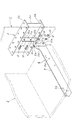
図1及び図2に示すように、金属製腕木4は、住宅用鉄骨製建物1の建物躯体を構成する長尺なH形鋼製梁材2に一端部が固着され他端部が建物外壁より室外側に突出して、バルコニーやエアコン室外機、床あるいは庇等の外装部材3の重量を支え、これを突出支持するためのもので、従来技術と同じように、長尺なH形鋼製梁材2にその長手方向適当間隔に複数個設けられており、これらの金属製腕木4は外装部材3を形成する図示しない根太や取付桟に腕木本体部6に設けた取付孔6aにボルト等によって固着されるようになっている。(特許文献1参照)   As shown in FIGS. 1 and 2, the metal brace 4 has one end fixed to a long H-shaped steel beam material 2 constituting the building frame of a residential steel building 1 and the other end is a building outer wall. It protrudes further to the outside, supports the weight of the exterior member 3 such as a balcony, an air conditioner outdoor unit, a floor or a fence, and supports it in a protruding manner. Like the prior art, it is made of a long H-shaped steel. A plurality of metal arms 4 are provided in the beam member 2 at appropriate intervals in the longitudinal direction. These metal arms 4 are bolts or the like in mounting holes 6a provided in the arm main body 6 on the joists or mounting bars (not shown) that form the exterior member 3. It is supposed to be fixed by. (See Patent Document 1)

建物躯体を構成するH形鋼製梁材2の構造は当然のことながら周知であり、上下のフランジ部2a,2b及びウエブ部2cと、両フランジ部2a,2b間にあってウエブ部2cに直交する軸線C1上に固着されウエブ部2cの座屈を防止してこれを補強するためにウエブ部2c長手方向適当間隔に設けられた補強板であるスチフナー7とからなる。   The structure of the H-shaped steel beam material 2 constituting the building frame is naturally well known, and is located between the upper and lower flange portions 2a and 2b and the web portion 2c, and both the flange portions 2a and 2b, and is orthogonal to the web portion 2c. It consists of a stiffener 7 which is a reinforcing plate fixed on the axis C1 and provided at an appropriate interval in the longitudinal direction of the web portion 2c in order to prevent buckling of the web portion 2c and reinforce it.

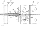
金属製腕木4は、前記H形鋼製梁材2に固着される根元部5と、外装部材3を支持するために根元部5から室外側に突出する腕木本体部6とからなり、金属製腕木4の前記根元部5は、図2に示すように、前記スチフナー7の軸線C1より側面7a側に偏位した軸線C2上にあり該側面7aに沿って固着される根元部本体部5aと、該根元部本体部5aの軸線C2側より前記スチフナー7の軸線C1側に芯振りして前記腕木本体部6を前記スチフナーの軸線C1の延長線C3上に配置するための根元部芯振り部5bとからなる。   The metal arm 4 includes a base portion 5 fixed to the H-shaped steel beam member 2 and an arm main body portion 6 that protrudes from the root portion 5 to the outdoor side in order to support the exterior member 3. As shown in FIG. 2, the root portion 5 of the arm 4 is on an axis C2 that is offset from the axis C1 of the stiffener 7 toward the side surface 7a, and is fixed along the side surface 7a. The root portion core swinging portion for pivoting from the axis C2 side of the root portion main body portion 5a to the axis C1 side of the stiffener 7 and placing the arm main body portion 6 on the extension line C3 of the stiffener axis C1. 5b.

又、H形鋼製梁材2の外部側にはプレハブ住宅等の規格化(モジュール化)した外壁構造の外壁部材70が取り付けられるようになっており、この外壁部材70は、リップ溝形鋼からなる外壁骨枠71とこれに一体的に取り付けられている外壁材72とからなり、これらの外壁部材70には一定間隔に室内外に貫通する目地73が存在し、この目地73は、H形鋼製梁材2に固着されるスチフナー7の軸線C1の延長線C3上に配置されるように規格化(モジュール化)されているが、本発明に係る金属製腕木4の腕木本体部6は、上述のように前記スチフナーの軸線C1の延長線C3上に配置されるようになっているため、金属製腕木40の板状腕木本体部50は上記モジュール化されてなる目地73を貫通して外壁部材70から室外側に正確に延びて配設することができる。   An outer wall member 70 having a standardized (modularized) outer wall structure such as a prefabricated house is attached to the outer side of the H-shaped steel beam member 2, and the outer wall member 70 is a lip groove steel. The outer wall bone frame 71 and the outer wall member 72 attached integrally therewith are provided, and these outer wall members 70 have joints 73 penetrating indoors and outdoors at regular intervals. It is standardized (modularized) so as to be arranged on the extension line C3 of the axis C1 of the stiffener 7 fixed to the steel beam member 2, but the arm main body 6 of the metal arm 4 according to the present invention. Is arranged on the extension line C3 of the stiffener axis C1 as described above, the plate-like arm main body portion 50 of the metal arm 40 penetrates the joint 73 formed as a module. From the outer wall member 70 to the outdoor side It can be disposed extending in the probability.

スチフナー7と根元部本体部5aとには同軸上にボルト挿通孔10a,10b,11a,11bが形成され、これらボルト挿通孔10a,10b,11a,11bにボルト12を挿通させ、該ボルト12にワッシャー16を介してナット13をねじ込むことによって、根元部本体部5aがスチフナー7の側面7aに沿って取り付けられるようになっている。なお、ボルト12は高力ボルトであって、これにナット13をトルシア形高力ボルト専用電動レンチでピンテールが破断するまで締め付けることが好ましい。   Bolt insertion holes 10 a, 10 b, 11 a, 11 b are formed coaxially in the stiffener 7 and the root part main body part 5 a, and bolts 12 are inserted into these bolt insertion holes 10 a, 10 b, 11 a, 11 b, By screwing the nut 13 through the washer 16, the root portion main body 5 a is attached along the side surface 7 a of the stiffener 7. Note that the bolt 12 is a high-strength bolt, and it is preferable that the nut 13 is tightened on the bolt 12 with a Torcia-type high-strength bolt electric wrench until the pin tail is broken.

そして本発明の最大の特徴とする構成であるが、金属製腕木4の根元部5を鋳鋼によって、すなわち前記根元部本体部5aと前記根元部芯振り部5bとを鋳鋼によって一体に鋳造形成したことを特徴とする。これがために、従来のように根元部本体部と、根元部芯振り部とを別々に正確な製作工程を必要としたり、根元部本体部に開先切削形成工程を必要としたり、この開先部に溶接を施す工程を必要としたり、根元部本体部と根元部芯振り部との隅角部に隅肉溶接を施す工程を必要とした、これらの工程を経ることが全くなくなり、更には前記根元部5が鋳鋼により形成されることによって、鋳鋼製根元部5の全体が熱処理後の摩擦面処理によって所定の摩擦係数の摩擦面に形成することができ、従来のように、板状根元部本体部の表面のショットブラスト等の摩擦面処理工程を経る必要も全くない。これがために金属製腕木4を製作するにあたって、大幅に製作費を軽減することができる。   And it is the structure which makes the most characteristic of this invention, but the base part 5 of the metal arm 4 was integrally formed by casting steel, that is, the base part main body part 5a and the base part core swing part 5b were integrally cast by cast steel. It is characterized by that. For this reason, the root part main body part and the root part core swing part need to be accurately manufactured separately as in the prior art, or the root part main body part requires a groove cutting forming process. No need to go through these steps, requiring a step of welding the part, or a step of applying fillet welding to the corner part of the base part main body part and the base part core swing part, and By forming the root portion 5 from cast steel, the entire cast steel root portion 5 can be formed on a friction surface having a predetermined friction coefficient by a friction surface treatment after heat treatment. There is no need to go through a friction surface treatment process such as shot blasting on the surface of the body part. Therefore, when manufacturing the metal arm 4, the manufacturing cost can be greatly reduced.

なお大きな重量物である室外建造物3を支える金属製腕木4は、その根元部5が過大な重量に耐える材料で形成されなければならない。この場合、鍛造で形成することは可能であるが、製作費が非常に高くつき実用的でない、又鋳鉄では強度不足であり、これらの理由によって、金属製腕木4の根元部5が強度の高い指定建築材料でもある鋳鋼によって鋳造形成されることになったが、この鋳鋼で金属製腕木4の根元部5を一体形成する場合に、前述のように該根元部5に鋼材等の金属製の腕木本体部6が溶接によって接合されなければならない。このため、鋳鋼としては、溶接性の良好な材料である溶接構造用鋳鋼品(SCW材)が採用される。そして、特にそのうち、JIS G 5102で 規定されているSCW480が、強度上、又、良好な溶接性から採用されることが好ましい。   It should be noted that the metal arm 4 that supports the outdoor structure 3 that is a heavy object must be formed of a material having a root portion 5 that can withstand an excessive weight. In this case, it is possible to form by forging, but the production cost is very high and is not practical, and cast iron has insufficient strength. For these reasons, the base portion 5 of the metal arm 4 is high in strength. The cast steel, which is also a designated building material, was cast and formed. However, when the base portion 5 of the metal arm 4 is integrally formed with this cast steel, the base portion 5 is made of a metal such as steel as described above. The arm main body 6 must be joined by welding. For this reason, as cast steel, a cast steel product for welded structure (SCW material) which is a material having good weldability is employed. Of these, SCW480 defined in JIS G 5102 is particularly preferred because of its strength and good weldability.

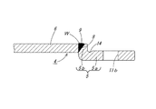
しかも、鋳鋼によって前記根元部5が一体形成されることによって、特に図4に拡大して示すように、前記根元部5の前記根元部芯振り部5bの先端部には、略傾斜状平面となる開先部8が予め鋳造形成されており、従来のように根元部芯振り部に開先部を切削形成する工程を必要としないから、この面からも製作費を軽減することができる。   Moreover, when the root portion 5 is integrally formed of cast steel, as shown particularly in an enlarged view in FIG. 4, the tip portion of the root portion core swinging portion 5 b of the root portion 5 has a substantially inclined flat surface. Since the groove portion 8 to be formed is previously cast and does not require the step of cutting and forming the groove portion in the root portion core swinging portion as in the prior art, the manufacturing cost can be reduced also from this surface.

又、図2又は図3に示すように、前記根元部5の前記根元部芯振り部5bと前記腕木本体部6とは溶接Wにより一体に接合されてなるが、この際に、前記根元部5の前記根元部芯振り部5bに鋳造形成されてなる一箇所の開先部8に、突き合わせ溶接によって溶接金属9が埋め込まれるため、最小限の溶接工程で上記両者を強力に一体接合することができる。この際、根元部5の全体が,前述のようにその製造工程によって熱処理後の所定の摩擦面処理されているため、溶接金属9は、該摩擦面に受け止められて開先部の対応する隅角部に隅肉溶接を行う必要がないことが実験の結果判明している。   As shown in FIG. 2 or FIG. 3, the root portion core swinging portion 5b of the root portion 5 and the arm main body portion 6 are integrally joined by welding W. At this time, the root portion Since the weld metal 9 is embedded by butt welding in one groove portion 8 formed by casting on the root portion core swinging portion 5b of the base portion 5, the above-mentioned two members are strongly joined together with a minimum welding process. Can do. At this time, since the entire root portion 5 has been subjected to the predetermined friction surface treatment after the heat treatment by the manufacturing process as described above, the weld metal 9 is received by the friction surface and corresponds to the corresponding corner of the groove portion. Experiments have shown that it is not necessary to fillet the corners.

なお、この溶接金属9は、例えば、JASS(建築工事標準仕様書)の6(鉄骨工事)に準拠した溶接方法、すなわち、開先部8に例えば三層の突き合わせ溶接によって埋め込んだ金属である。この溶接金属9を前記開先部8に埋め込むことによって前記根元部5の前記根元部芯振り部5bと前記腕木本体部6とは一体に強固に接合されてなる。   The weld metal 9 is, for example, a welding method compliant with JASS (Building Construction Standard Specification) 6 (steel work), that is, a metal embedded in the groove portion 8 by, for example, three-layer butt welding. By embedding the weld metal 9 in the groove portion 8, the root portion core swinging portion 5b of the root portion 5 and the arm main body portion 6 are integrally and firmly joined together.

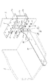
又、図2、図3、特に図4に示すように、前記根元部5の前記根元部本体部5aと前記根元部芯振り部5bとのコーナー部にはスチフナー7との衝突を避けるための肉逃し部14が前記開先部8と同じように鋳造形成されてなるため、金属製腕木4の根元部5をスチフナー7の側面7aにボルト12及びナット13によって固着する際に、スチフナー7の端縁が根元部芯振り部5bと根元部本体部5aとのコーナー部に衝突することがなく、前記根元部5をスチフナー7に正確に且つ容易に取り付けることができる。   Also, as shown in FIGS. 2 and 3, particularly FIG. 4, a corner portion between the base portion main body portion 5 a and the root portion core swing portion 5 b of the root portion 5 is for avoiding a collision with a stiffener 7. Since the meat escape portion 14 is cast and formed in the same manner as the groove portion 8, when the root portion 5 of the metal arm 4 is fixed to the side surface 7 a of the stiffener 7 with the bolt 12 and the nut 13, the stiffener 7 The end edge does not collide with the corner portion between the root portion core swinging portion 5b and the root portion main body portion 5a, and the root portion 5 can be attached to the stiffener 7 accurately and easily.

更に又、図4に示すように、前記根元部5の前記根元部本体部5aには前記上下一対のボルト挿通孔10a,10bを避けて、強度を落とすことなく肉落とし部15が同じく鋳造形成されるため、根元部5の高価な鋳鋼の使用量を可能な限り減少して金属製腕木4の製作費を軽減することができる。   Furthermore, as shown in FIG. 4, the base portion main body portion 5a of the base portion 5 avoids the pair of upper and lower bolt insertion holes 10a and 10b, and the thickness reduction portion 15 is also cast and formed without reducing the strength. Therefore, the amount of expensive cast steel used for the base portion 5 can be reduced as much as possible to reduce the manufacturing cost of the metal arm 4.

又、本発明に係る住宅は、上記構成の金属製腕木4を用いて外装部材3が装備されるため、該外装部材3を長期にわたって安定して住宅の支持させることができる。   Moreover, since the housing according to the present invention is equipped with the exterior member 3 using the metal arm 4 having the above-described configuration, the exterior member 3 can be stably supported over a long period of time.

1 鉄骨製建物
2 H形鋼製梁材
2a フランジ部
2b フランジ部
2c ウエブ部
3 外装部材
4 金属製腕木
5 根元部
5a 根元部本体部
5b 根元部芯振り部
6 腕木本体部
7 スチフナー
C1 スチフナー7の軸線
7a スチフナー7の側面
C2 根元部本体部5aの軸線
C3 スチフナー7に軸線C1延長線上に取り付けられる腕木本体部6の延長線 8 根元部芯振り部5bに鋳造形成される開先部
9 開先部8に埋め込まれる溶接金属
10a ボルト挿通孔
10b ボルト挿通孔
11a ボルト挿通孔
11b ボルト挿通孔
12 ボルト
13 ナット
14 肉逃し部
15 肉落とし部


DESCRIPTION OF SYMBOLS 1 Steel building 2 H-shaped steel beam material 2a Flange part 2b Flange part 2c Web part 3 Exterior member 4 Metal arm 5 Root part 5a Root part main part 5b Root part core swing part 6 Arm main part 7 Stiffener C1 Stiffener 7 Axis 7a Side surface of stiffener 7 C2 Axis line of root portion main body portion 5a C3 Extension line of arm main body portion 6 attached to stiffener 7 on axis C1 extension line 8 Groove portion formed by casting at root portion core swinging portion 5b 9 Open Weld metal embedded in the tip 8 10a Bolt insertion hole 10b Bolt insertion hole 11a Bolt insertion hole 11b Bolt insertion hole 12 Bolt 13 Nut 14 Meat escape portion 15 Meat removal portion


Claims (8)

鉄骨製建物の建物躯体を構成する長尺なH形鋼製梁材に一端部が固着され他端部が建物外壁より室外側に突出して、バルコニーやエアコン室外機、床あるいは庇等の外装部材を突出支持するための金属製腕木であって、該金属製腕木は、前記H形鋼製梁材に固着される根元部と、外装部材を支持するために根元部から室外側に突出する腕木本体部とからなり、H形鋼製梁材は、上下のフランジ部及びウエブ部と、両フランジ部間にあってウエブ部に直交する軸線上に固着されるスチフナーとからなり、金属製腕木の前記根元部は、前記スチフナーの軸線より側面側に偏位した軸線上にあってスチフナーの側面に沿って固着される根元部本体部と、該根元部本体部の軸線より前記スチフナーの軸線側に芯振りして前記腕木本体部を前記スチフナーの軸線の延長線上に配置するための根元部芯振り部とからなり、前記根元部本体部と前記根元部芯振り部とは鋳鋼によって一体形成されてなる金属製腕木。   One end part is fixed to the long H-shaped steel beam material constituting the building frame of a steel frame building, and the other end part projects outside from the building outer wall, and exterior members such as balconies, air conditioner outdoor units, floors, fences, etc. A metal arm for projecting and supporting the base, the base arm fixed to the beam of the H-shaped steel, and an arm that projects from the base to the outdoor side to support the exterior member The H-shaped steel beam material is composed of upper and lower flange portions and web portions, and a stiffener between the flange portions and fixed on an axis perpendicular to the web portions. The base part is on an axis deviated to the side of the stiffener from the side of the stiffener, and is fixed along the side of the stiffener. The base is pivoted from the base of the base to the stiffener axis. Then, the arm main body is attached to the stiffener. Of consists of a root portion core swing unit for placement on an extension line of the axis, the metal bracket comprising integrally formed by cast steel and the said base portion main body base portion core swing section. 金属製腕木の腕木本体部は外壁部材に形成される目地を貫通して室外側に延びるようになっている請求項1に記載の金属製腕木。   The metal arm according to claim 1, wherein the arm main body of the metal arm extends through the joint formed in the outer wall member and extends outward. 前記根元部の前記根元部芯振り部と前記腕木本体部とは溶接により一体に接合されてなる請求項1又は2に記載の金属製腕木。   The metal brace according to claim 1 or 2, wherein the root portion core swinging portion and the brace main body portion of the root portion are integrally joined by welding. 前記根元部の前記根元部芯振り部には、鋳鋼による一体形成の際に、開先部が鋳造形成され、該開先部に溶接金属を埋め込むことによって、前記根元部の前記根元部芯振り部と前記腕木本体部とは一体に接合されてなる請求項3に記載の金属製腕木。 A groove portion is cast and formed in the root portion core swing portion of the root portion when cast steel is integrally formed, and the root portion core swing of the root portion is embedded by embedding a weld metal in the groove portion. The metal arm according to claim 3, wherein the arm and the arm main body are integrally joined. 前記スチフナーと前記根元部の前記根元部本体部には夫々上下一対のボルト挿通孔が形成され、上下両一対のボルト挿通孔にボルトを挿通して、該ボルトにナットをねじ込むことによって、前記根元部本体部はスチフナーの軸線より側面側に偏位した軸線上にあってスチフナーの側面に沿って固着されてなる請求項1〜4の何れかに記載の金属製腕木。   A pair of upper and lower bolt insertion holes are formed in the base portion of the stiffener and the root portion, respectively, and a bolt is inserted into the pair of upper and lower bolt insertion holes, and a nut is screwed into the bolt, thereby The metal arm according to any one of claims 1 to 4, wherein the main part is on an axis deviated from the axis of the stiffener to the side and is fixed along the side of the stiffener. 前記根元部の前記根元部本体部と前記根元部芯振り部とのコーナー部にはスチフナーとの衝突を避けるための肉逃し部が形成されてなる請求項1〜5の何れかに記載の金属製腕木。   The metal according to any one of claims 1 to 5, wherein a meat relief portion for avoiding a collision with a stiffener is formed at a corner portion of the root portion main body portion and the root portion core swing portion of the root portion. Arm made of arm. 前記根元部5の前記根元部本体部5aには前記上下一対のボルト挿通孔を避けて肉落とし部が形成されてなる請求項1〜6の何れかに記載の金属製腕木。   The metal brace according to any one of claims 1 to 6, wherein a meat drop portion is formed in the base portion main body portion 5a of the base portion 5 so as to avoid the pair of upper and lower bolt insertion holes. 請求項1〜7の何れか記載の金属製腕木を用いてなる住宅。   A house made of the metal arm according to any one of claims 1 to 7.
JP2016116588A 2016-06-10 2016-06-10 Metal arm Active JP6446405B2 (en)

Priority Applications (1)

Application Number Priority Date Filing Date Title
JP2016116588A JP6446405B2 (en) 2016-06-10 2016-06-10 Metal arm

Applications Claiming Priority (1)

Application Number Priority Date Filing Date Title
JP2016116588A JP6446405B2 (en) 2016-06-10 2016-06-10 Metal arm

Publications (2)

Publication Number Publication Date
JP2017218871A JP2017218871A (en) 2017-12-14
JP6446405B2 true JP6446405B2 (en) 2018-12-26

Family

ID=60655953

Family Applications (1)

Application Number Title Priority Date Filing Date
JP2016116588A Active JP6446405B2 (en) 2016-06-10 2016-06-10 Metal arm

Country Status (1)

Country Link
JP (1) JP6446405B2 (en)

Family Cites Families (12)

* Cited by examiner, † Cited by third party
Publication number Priority date Publication date Assignee Title
JPS5480248A (en) * 1977-12-09 1979-06-26 Kubota Ltd Welding method for heat-resisting cast steel
JPH0354485Y2 (en) * 1986-10-30 1991-12-02
JPH0529281Y2 (en) * 1986-12-20 1993-07-27
JP2517183B2 (en) * 1991-08-29 1996-07-24 ミサワホーム株式会社 Building outer structure
JP2690846B2 (en) * 1993-05-27 1997-12-17 川崎重工業株式会社 Hull bracket structure
JPH09228467A (en) * 1996-02-23 1997-09-02 Seiko Sangyo Kk Assembling structure of balcony or the like
JPH11229546A (en) * 1998-02-13 1999-08-24 Natl House Ind Co Ltd Eaves support structure
JP2005207703A (en) * 2004-01-26 2005-08-04 Sekisui House Ltd Air conditioner outdoor unit mounting structure in base isolated building
JP2005213871A (en) * 2004-01-29 2005-08-11 Sekisui House Ltd Outdoor-machine depot for air-conditioning building
US8959849B1 (en) * 2007-11-21 2015-02-24 The Steel Network, Inc. Light steel frame structure for deck
JP2010112104A (en) * 2008-11-07 2010-05-20 Sekisui House Ltd Pent-roof
US20140069049A1 (en) * 2012-09-10 2014-03-13 John Oltrogge Framing bracket

Also Published As

Publication number Publication date
JP2017218871A (en) 2017-12-14

Similar Documents

Publication Publication Date Title
JP4112564B2 (en) Column and beam connection structure
EP2492408A1 (en) Joint structure for building frame
JP5069335B2 (en) Direct connection method of beam and inner diaphragm of steel structure column beam joint
JP6446405B2 (en) Metal arm
JP6306762B1 (en) Light steel building structure
JP2010281192A (en) Joint fitting, fixation fitting and fixing pin for building
JP4667114B2 (en) Method of joining beam and column
JP5014824B2 (en) Wall panel mounting structure and mounting method
JP4972363B2 (en) Column beam connection structure and column beam connection method
US20070234666A1 (en) Integral connectors in tubular beams for building structures
JP2009174303A (en) Wood material connection reinforcing joint hardware
JP4260736B2 (en) Steel house bearing wall structure
JP2021055465A (en) Horizontal structural plane reinforcing plate and horizontal structural plane reinforcing structure
JP2020051038A (en) Fixing structure of spandrel wall panel
JP6902738B2 (en) Joining hardware and joining structure using this
JP7084028B2 (en) Seismic control structure and construction method of seismic control structure
AU2009101214A4 (en) Connection Bracket and Method
JP2008007997A (en) Connection structure and connection metal fitting of wooden building
JPH11324115A (en) Joint metal fitting for building
KR20220025796A (en) Rectangular pipe connector for lightweight steel structure and rectangular pipe connection method
JP3355389B2 (en) Reinforcement metal fittings and wooden buildings
JPH1150535A (en) Reinforcing tool for construction
JP2004183467A (en) Fixing metal fitting for timber corner
JP2004183477A (en) Joint metal fitting
JP2005264710A5 (en)

Legal Events

Date Code Title Description
A621 Written request for application examination

Free format text: JAPANESE INTERMEDIATE CODE: A621

Effective date: 20180117

TRDD Decision of grant or rejection written
A977 Report on retrieval

Free format text: JAPANESE INTERMEDIATE CODE: A971007

Effective date: 20181024

A01 Written decision to grant a patent or to grant a registration (utility model)

Free format text: JAPANESE INTERMEDIATE CODE: A01

Effective date: 20181109

A61 First payment of annual fees (during grant procedure)

Free format text: JAPANESE INTERMEDIATE CODE: A61

Effective date: 20181203

R150 Certificate of patent or registration of utility model

Ref document number: 6446405

Country of ref document: JP

Free format text: JAPANESE INTERMEDIATE CODE: R150

S533 Written request for registration of change of name

Free format text: JAPANESE INTERMEDIATE CODE: R313533

R350 Written notification of registration of transfer

Free format text: JAPANESE INTERMEDIATE CODE: R350

R250 Receipt of annual fees

Free format text: JAPANESE INTERMEDIATE CODE: R250

R250 Receipt of annual fees

Free format text: JAPANESE INTERMEDIATE CODE: R250

R250 Receipt of annual fees

Free format text: JAPANESE INTERMEDIATE CODE: R250