JP6439382B2 - Power working machine - Google Patents

Power working machine Download PDF

Info

Publication number
JP6439382B2
JP6439382B2 JP2014220309A JP2014220309A JP6439382B2 JP 6439382 B2 JP6439382 B2 JP 6439382B2 JP 2014220309 A JP2014220309 A JP 2014220309A JP 2014220309 A JP2014220309 A JP 2014220309A JP 6439382 B2 JP6439382 B2 JP 6439382B2
Authority
JP
Japan
Prior art keywords
housing
motor
working machine
substrate case
axis
Prior art date
Legal status (The legal status is an assumption and is not a legal conclusion. Google has not performed a legal analysis and makes no representation as to the accuracy of the status listed.)
Active
Application number
JP2014220309A
Other languages
Japanese (ja)
Other versions
JP2016087696A5 (en
JP2016087696A (en
Inventor
裕太 野口
裕太 野口
和隆 岩田
和隆 岩田
一彦 船橋
一彦 船橋
智明 須藤
智明 須藤
Current Assignee (The listed assignees may be inaccurate. Google has not performed a legal analysis and makes no representation or warranty as to the accuracy of the list.)
Koki Holdings Co Ltd
Original Assignee
Koki Holdings Co Ltd
Priority date (The priority date is an assumption and is not a legal conclusion. Google has not performed a legal analysis and makes no representation as to the accuracy of the date listed.)
Filing date
Publication date
Application filed by Koki Holdings Co Ltd filed Critical Koki Holdings Co Ltd
Priority to JP2014220309A priority Critical patent/JP6439382B2/en
Priority to CN201580057419.3A priority patent/CN107148327B/en
Priority to EP15854049.2A priority patent/EP3213877B1/en
Priority to US15/522,294 priority patent/US20170312902A1/en
Priority to PCT/JP2015/079711 priority patent/WO2016067997A1/en
Publication of JP2016087696A publication Critical patent/JP2016087696A/en
Publication of JP2016087696A5 publication Critical patent/JP2016087696A5/ja
Application granted granted Critical
Publication of JP6439382B2 publication Critical patent/JP6439382B2/en
Active legal-status Critical Current
Anticipated expiration legal-status Critical

Links

Images

Description

本発明は、モータの動力で作業工具を動作させる動力作業機に関する。   The present invention relates to a power working machine that operates a work tool with the power of a motor.

モータの動力で作業工具を動作させる動力作業機が、特許文献1に記載されている。特許文献1に記載された動力作業機は、ハンマドリルである。特許文献1に記載されたハンマドリルは、ハウジングに設けられたモータと、モータの動力により回転され、かつ、作業工具を支持する工具支持部材と、モータの動力を打撃力に変換する動力変換機構と、打撃力を作業工具に伝達する中間子と、を備えている。動力変換機構は、円筒状のシリンダ、シリンダ内に設けたピストン、シリンダ内に配置され、かつ、ピストンとの間に圧力室を形成する打撃子と、を有する。ピストン、打撃子、中間子は、シリンダの中心線に沿った方向に動作する動作部材である。   A power work machine that operates a work tool with the power of a motor is described in Patent Document 1. The power working machine described in Patent Document 1 is a hammer drill. The hammer drill described in Patent Document 1 includes a motor provided in a housing, a tool support member that is rotated by the power of the motor and supports a work tool, and a power conversion mechanism that converts the power of the motor into a striking force. And an intermediate for transmitting the striking force to the work tool. The power conversion mechanism includes a cylindrical cylinder, a piston provided in the cylinder, and a striker disposed in the cylinder and forming a pressure chamber between the piston. The piston, the striker, and the intermediate element are operating members that move in a direction along the center line of the cylinder.

また、ハンマドリルは、ハンマモードとハンマドリルモードとを切り替え可能である。ハンマモードが選択されると、モータの動力が打撃力に変換され、その打撃力は作業工具に伝達される。ハンマドリルモードが選択されると、作業工具に打撃力が伝達されることに加え、作業工具に回転力が伝達される。   The hammer drill can be switched between a hammer mode and a hammer drill mode. When the hammer mode is selected, the power of the motor is converted into a striking force, and the striking force is transmitted to the work tool. When the hammer drill mode is selected, in addition to the impact force being transmitted to the work tool, the rotational force is transmitted to the work tool.

特許文献1に記載されたハンマドリルは、ハウジングにセンサユニットが設けられている。センサユニットは、制御基板と、制御基板に取り付けた傾きセンサと、を備えている。傾きセンサは、作業工具を地面に押し付け、かつ、作業工具を垂直とした状態を0度とし、ハウジングを傾けた場合に、0度に対する作業工具の傾き角度を検出するセンサである。そして、作業工具の傾き角度に応じて、異なる色のLED(light emitting diode)ランプを点灯する制御が行われる。また、センサユニットは、傾きセンサを取り付けたセンサ基板を包むように配置した弾性部材を備えている。さらに、制御基板に伝達された振動を低減でき、傾きセンサの破損を防止できる。   In the hammer drill described in Patent Document 1, a sensor unit is provided in a housing. The sensor unit includes a control board and a tilt sensor attached to the control board. The tilt sensor is a sensor that detects the tilt angle of the work tool with respect to 0 degrees when the work tool is pressed against the ground and the work tool is perpendicular to 0 degrees and the housing is tilted. Then, control is performed to turn on LED (light emitting diode) lamps of different colors according to the tilt angle of the work tool. In addition, the sensor unit includes an elastic member disposed so as to wrap the sensor substrate to which the tilt sensor is attached. Furthermore, the vibration transmitted to the control board can be reduced, and the tilt sensor can be prevented from being damaged.

特開2013−94870号公報JP 2013-94870 A

しかし、特許文献1に記載された動力作業機は、制御基板とハウジングとの間に弾性体が設けられていることに止まり、制御基板の振動を十分に低減できない可能性があった。   However, the power working machine described in Patent Document 1 is limited to the provision of an elastic body between the control board and the housing, and there is a possibility that the vibration of the control board cannot be sufficiently reduced.

本発明の目的は、ハウジングの振動が制御基板に伝達されることを抑制できる、動力作業機を提供することにある。   The objective of this invention is providing the power working machine which can suppress that the vibration of a housing is transmitted to a control board.

本発明は、モータの動力で第1軸線に沿った方向に作業工具を動作させる動力作業機であって、前記モータを制御する制御基板と、前記制御基板を収容する基板ケースと、前記基板ケースを支持するハウジングと、前記基板ケースと前記ハウジングとの間に介在させた弾性体と、を有し、前記ハウジングは、前記モータを収容した第1ハウジングと、前記第1ハウジングに固定され前記基板ケースを収容した第2ハウジングと、を備え、前記基板ケースは、前記第1軸線と交差する第2軸線に沿った方向に延びるプレート部と、前記プレート部の外周縁に設けられ、前記プレート部から前記第1軸線に沿った方向に延びる側壁と、を備え、前記弾性体は、前記第1軸線に沿った方向で、前記プレート部と前記第1ハウジングとの間、及び/または、前記側壁と前記第2ハウジングとの間に介在されている。 The present invention is a power working machine that operates a work tool in a direction along a first axis with the power of a motor, and includes a control board that controls the motor, a board case that houses the control board, and the board case A housing supporting the motor, and an elastic body interposed between the substrate case and the housing, the housing being fixed to the first housing , the first housing housing the motor, and the substrate. A second housing housing the case , wherein the substrate case is provided on a plate portion extending in a direction along a second axis intersecting the first axis, and on an outer peripheral edge of the plate portion, and the plate portion and a side wall extending in a direction along the first axis from said elastic body, said first direction along the axis, between said plate portion first housing, and / or Is interposed between said side wall second housing.

本発明では、ハウジングの振動が弾性体により低減され、ハウジングの振動が制御基板に伝達されることを抑制できる。   In the present invention, the vibration of the housing is reduced by the elastic body, and the vibration of the housing can be prevented from being transmitted to the control board.

本発明の実施の形態1に相当する電動作業機の正面断面図である。1 is a front sectional view of an electric working machine corresponding to Embodiment 1 of the present invention. 図1の電動作業機の制御回路を示すブロック図である。It is a block diagram which shows the control circuit of the electric working machine of FIG. 図1の電動作業機の要部を拡大した正面断面図である。It is front sectional drawing to which the principal part of the electric working machine of FIG. 1 was expanded. 図1の電動作業機に用いる制御ユニットの側面図である。It is a side view of the control unit used for the electric working machine of FIG. 図4に示すコネクタとリード線との接続構造を示す断面図である。It is sectional drawing which shows the connection structure of the connector and lead wire shown in FIG. 図1の電動作業機に設けた表示ケースの断面図である。It is sectional drawing of the display case provided in the electric working machine of FIG. 図6に示す表示ケースのカバーを取り外した側面図である。It is the side view which removed the cover of the display case shown in FIG. 本発明の実施の形態2に相当する電動作業機の一部を示す正面断面図である。It is front sectional drawing which shows a part of electric working machine equivalent to Embodiment 2 of this invention.

以下、本発明の実施の形態における動力作業機を図面に基づいて詳細に説明する。   Hereinafter, the power working machine in embodiment of this invention is demonstrated in detail based on drawing.

(実施の形態1)
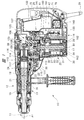
本発明の実施の形態1における動力作業機を、図1〜図7を参照して説明する。動力作業機としての電動作業機10は、ハンマドリルとも言われる。電動作業機10はコンクリートや石材等の対象物に穴あけ加工等を行うために使用される。
(Embodiment 1)
The power working machine in Embodiment 1 of this invention is demonstrated with reference to FIGS. The electric working machine 10 as a power working machine is also called a hammer drill. The electric working machine 10 is used for drilling a target such as concrete or stone.

電動作業機10は作業機本体12を備え、作業機本体12は、シリンダハウジング13と中間ケース14とハンドル15とモータハウジング20と底部カバー17とを互いに固定して組み立てられている。底部カバー17は、ねじ部材162によりモータハウジング20に固定されている。底部カバー17は、軸線B1に沿った方向で、モータハウジング20の隣に配置されている。底部カバー17を貫通する通気口17aが設けられている。   The electric work machine 10 includes a work machine main body 12, and the work machine main body 12 is assembled by fixing a cylinder housing 13, an intermediate case 14, a handle 15, a motor housing 20, and a bottom cover 17 to each other. The bottom cover 17 is fixed to the motor housing 20 by a screw member 162. The bottom cover 17 is disposed next to the motor housing 20 in a direction along the axis B1. A vent hole 17 a penetrating the bottom cover 17 is provided.

シリンダハウジング13は筒形状であり、シリンダハウジング13内に円筒形状のシリンダ18が設けられている。シリンダ18は軸線A1を中心として配置されており、シリンダ18と同心状に、円筒形状の工具保持具19が設けられている。工具保持具19は、シリンダハウジング13内に設けられており、工具保持具19は、軸受16により回転可能に支持されている。シリンダ18と工具保持具19は一体回転可能に連結されている。工具保持具19に先端工具11が取り付けられ、シリンダ18の回転力は先端工具11に伝達される。   The cylinder housing 13 has a cylindrical shape, and a cylindrical cylinder 18 is provided in the cylinder housing 13. The cylinder 18 is disposed around the axis A <b> 1, and a cylindrical tool holder 19 is provided concentrically with the cylinder 18. The tool holder 19 is provided in the cylinder housing 13, and the tool holder 19 is rotatably supported by the bearing 16. The cylinder 18 and the tool holder 19 are connected so as to be integrally rotatable. The tip tool 11 is attached to the tool holder 19, and the rotational force of the cylinder 18 is transmitted to the tip tool 11.

工具保持具19内からシリンダ18内に亘って、金属製の中間打撃子21が設けられている。中間打撃子21は、軸線A1に沿った方向に往復動自在である。シリンダ18内には、中間打撃子21を打撃する打撃子22が設けられている。打撃子22は、軸線A1に沿った方向に往復動作可能である。また、シリンダ18内にピストン23が配置されており、ピストン23は軸線A1に沿った方向に往復動作可能である。シリンダ18内であって、打撃子22とピストン23との間に空気室24が設けられている。   A metal intermediate striker 21 is provided from the tool holder 19 to the cylinder 18. The intermediate striker 21 can reciprocate in the direction along the axis A1. A striker 22 that strikes the intermediate striker 21 is provided in the cylinder 18. The striker 22 can reciprocate in the direction along the axis A1. A piston 23 is disposed in the cylinder 18, and the piston 23 can reciprocate in a direction along the axis A1. An air chamber 24 is provided in the cylinder 18 between the striker 22 and the piston 23.

中間ケース14は、軸線A1に沿った方向でハンドル15とシリンダハウジング13との間に配置されている。モータハウジング20は、シリンダハウジング13及び中間ケース14に対して固定されている。軸線A1に沿った方向におけるモータハウジング20の配置範囲は、軸線A1に沿った方向における中間ケース14の配置範囲と重なっている。ハンドル15は、アーチ形状に屈曲されており、ハンドル15の両端は、中間ケース14に取り付けられている。ハンドル15にトリガー132及び給電ケーブル25が設けられている。また、ハンドル15にトリガースイッチ26が設けられている。作業者がトリガー132を操作すると、トリガースイッチ26がオンオフされる。   The intermediate case 14 is disposed between the handle 15 and the cylinder housing 13 in a direction along the axis A1. The motor housing 20 is fixed to the cylinder housing 13 and the intermediate case 14. The arrangement range of the motor housing 20 in the direction along the axis A1 overlaps with the arrangement range of the intermediate case 14 in the direction along the axis A1. The handle 15 is bent in an arch shape, and both ends of the handle 15 are attached to the intermediate case 14. A trigger 132 and a power supply cable 25 are provided on the handle 15. In addition, a trigger switch 26 is provided on the handle 15. When the operator operates the trigger 132, the trigger switch 26 is turned on / off.

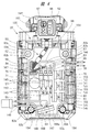
モータハウジング20は導電性の金属材料、例えば、アルミニウムにより一体成形されている。モータハウジング20は筒形状であり、モータハウジング20の内部に、モータケース27が配置されている。モータケース27は絶縁性の材料、例えば、合成樹脂により一体成形されている。モータケース27は、図3のように筒部27aを有し、モータケース27の筒部27aは、モータハウジング20に対して圧入固定されている。モータケース27は、筒部27aに連続する底部28を有し、底部28に軸孔29が形成されている。モータケース27内は、軸孔29及び通気口17aを介して作業機本体12の外部につながっている。   The motor housing 20 is integrally formed of a conductive metal material, for example, aluminum. The motor housing 20 has a cylindrical shape, and a motor case 27 is disposed inside the motor housing 20. The motor case 27 is integrally formed of an insulating material such as synthetic resin. The motor case 27 has a cylindrical portion 27 a as shown in FIG. 3, and the cylindrical portion 27 a of the motor case 27 is press-fitted and fixed to the motor housing 20. The motor case 27 has a bottom portion 28 that is continuous with the cylindrical portion 27 a, and a shaft hole 29 is formed in the bottom portion 28. The inside of the motor case 27 is connected to the outside of the work machine body 12 through the shaft hole 29 and the vent hole 17a.

また、モータケース27内にブラシレスモータ30が収容されている。このブラシレスモータ30は直流電動モータであり、ブラシレスモータ30は、筒形状のステータ31と、ステータ31の内側に配置されたロータ32と、を有している。ロータ32は、出力軸33と、出力軸33に固定されたロータコア32aと、を備えている。電動作業機10の正面視で、出力軸33の回転中心である軸線B1は、軸線A1と交差、具体的には、略直交する。モータハウジング20は、軸線B1に沿った方向で底部カバー17とシリンダハウジング13との間に配置されている。モータハウジング20は、底部カバー17内に位置する軸受支持部34を備えている。中間ケース14は、シリンダハウジング13内まで伸びた隔壁35を備え、隔壁35により支持された軸受36と、軸受支持部34により支持された軸受37と、が設けられている。2個の軸受36,37は、出力軸33の軸線B1に沿った方向で異なる位置に配置されている。出力軸33の第1端部は軸孔29に配置されており、出力軸33の第2端部は、中間ケース14内に配置されている。出力軸33のうち、中間ケース14内に配置された箇所の外周面に駆動ギヤ38が設けられている。   A brushless motor 30 is housed in the motor case 27. The brushless motor 30 is a direct current electric motor, and the brushless motor 30 includes a cylindrical stator 31 and a rotor 32 disposed inside the stator 31. The rotor 32 includes an output shaft 33 and a rotor core 32 a fixed to the output shaft 33. In a front view of the electric work machine 10, the axis B1 that is the rotation center of the output shaft 33 intersects the axis A1, specifically, substantially orthogonal. The motor housing 20 is disposed between the bottom cover 17 and the cylinder housing 13 in a direction along the axis B1. The motor housing 20 includes a bearing support portion 34 located in the bottom cover 17. The intermediate case 14 includes a partition wall 35 extending into the cylinder housing 13, and a bearing 36 supported by the partition wall 35 and a bearing 37 supported by a bearing support portion 34 are provided. The two bearings 36 and 37 are arranged at different positions in the direction along the axis B <b> 1 of the output shaft 33. The first end portion of the output shaft 33 is disposed in the shaft hole 29, and the second end portion of the output shaft 33 is disposed in the intermediate case 14. A drive gear 38 is provided on the outer peripheral surface of the output shaft 33 at a position arranged in the intermediate case 14.

モータケース27内にインシュレータ39が設けられている。インシュレータ39は軸線B1に沿った方向で、ブラシレスモータ30と軸受36との間に配置されている。インシュレータ39は、軸孔40を備えており、軸孔40内に出力軸33が配置されている。インシュレータ39は合成樹脂製であり、モータケース27内に回転しないように設けられている。インシュレータ39はステータ31に固定されている。   An insulator 39 is provided in the motor case 27. The insulator 39 is disposed between the brushless motor 30 and the bearing 36 in the direction along the axis B1. The insulator 39 includes a shaft hole 40, and the output shaft 33 is disposed in the shaft hole 40. The insulator 39 is made of synthetic resin and is provided in the motor case 27 so as not to rotate. The insulator 39 is fixed to the stator 31.

モータケース27内であって、インシュレータ39と軸受36との間にファン41が設けられている。ファン41は、出力軸33に固定されており、ファン41は出力軸33と共に回転して作業機本体12の外部の空気を、作業機本体12の内部に導入する役割を果たす。作業機本体12の外部と、中間ケース14の内部とが、通気口14aによりつながっている。   A fan 41 is provided in the motor case 27 between the insulator 39 and the bearing 36. The fan 41 is fixed to the output shaft 33, and the fan 41 rotates together with the output shaft 33 and plays a role of introducing air outside the work implement main body 12 into the work implement main body 12. The outside of the work machine body 12 and the inside of the intermediate case 14 are connected by a vent hole 14a.

ブラシレスモータ30を冷却するファン41の構造を、図3を参照して説明する。ファン41は環状であり、ファン41は出力軸33に取り付けられている。つまり、ファン41は出力軸33と共に回転する。ファン41は、非磁性材料である合成樹脂により成形されており、ファン41に永久磁石45が取り付けられている。永久磁石45は、軸線B1を中心とする環状体であり、永久磁石45の円周方向に沿って、異なる磁極であるN極とS極とが交互に配置されている。   The structure of the fan 41 that cools the brushless motor 30 will be described with reference to FIG. The fan 41 is annular, and the fan 41 is attached to the output shaft 33. That is, the fan 41 rotates with the output shaft 33. The fan 41 is formed of a synthetic resin that is a nonmagnetic material, and a permanent magnet 45 is attached to the fan 41. The permanent magnet 45 is an annular body centered on the axis B <b> 1, and N poles and S poles which are different magnetic poles are alternately arranged along the circumferential direction of the permanent magnet 45.

モータケース27内に接続基板47が設けられている。接続基板47は、例えばインシュレータ39に固定されている。つまり、接続基板47は、インシュレータ39を介してステータ31に取り付けられている。接続基板47は、軸線B1に沿った方向でステータ31と、ファン41に取り付けた永久磁石45との間に配置されている。接続基板47を厚さ方向に貫通する孔48が設けられており、出力軸33は孔48に配置されている。接続基板47は非磁性材料、例えば合成樹脂により成形されており、接続基板47に磁気センサS1〜S3が取り付けられている。   A connection board 47 is provided in the motor case 27. The connection substrate 47 is fixed to the insulator 39, for example. That is, the connection board 47 is attached to the stator 31 via the insulator 39. The connection board 47 is disposed between the stator 31 and the permanent magnet 45 attached to the fan 41 in the direction along the axis B1. A hole 48 penetrating the connection substrate 47 in the thickness direction is provided, and the output shaft 33 is disposed in the hole 48. The connection board 47 is formed of a non-magnetic material such as synthetic resin, and the magnetic sensors S1 to S3 are attached to the connection board 47.

図2は電動作業機10を制御する制御回路を示す。ブラシレスモータ30は商用電源49を動力源としており、商用電源49の電力は、給電ケーブル25を介してブラシレスモータ30のコイルに流れる。   FIG. 2 shows a control circuit for controlling the electric working machine 10. The brushless motor 30 uses a commercial power supply 49 as a power source, and the power of the commercial power supply 49 flows to the coil of the brushless motor 30 via the power supply cable 25.

また、ブラシレスモータ30のステータ31は、U相,V相,W相に対応するコイルU1,V1,W1を備え、ロータコア32aには円周方向に間隔をおいて、極性が異なる2種類の永久磁石32bが4個設けられており、異なる極性の永久磁石32bが交互に並べられている。3個の磁気センサS1〜S3は、ロータ32の回転位置を示す検出信号を出力する。3個の磁気センサS1〜S3は、3相のコイルU1,V1,W1に対応して設けられている。それぞれの磁気センサS1〜S3は、ファン41に取り付けた永久磁石45が発生する磁力を検出し、かつ、磁力を電気信号に変換して出力する非接触のセンサである。磁気センサS1〜S3は、ホール素子を用いることができる。   The stator 31 of the brushless motor 30 includes coils U1, V1, and W1 corresponding to the U phase, the V phase, and the W phase, and the rotor core 32a has two types of permanent magnets that are spaced apart in the circumferential direction and have different polarities. Four magnets 32b are provided, and permanent magnets 32b having different polarities are alternately arranged. The three magnetic sensors S1 to S3 output detection signals indicating the rotational position of the rotor 32. The three magnetic sensors S1 to S3 are provided corresponding to the three-phase coils U1, V1, and W1. Each of the magnetic sensors S <b> 1 to S <b> 3 is a non-contact sensor that detects the magnetic force generated by the permanent magnet 45 attached to the fan 41 and converts the magnetic force into an electric signal and outputs the electric signal. Hall elements can be used for the magnetic sensors S1 to S3.

電動作業機10は、各コイルU1,V1,W1に供給する電流を制御するインバータ回路121を有している。商用電源49とインバータ回路121との間の電気回路に、商用電源49の交流電流を直流電流に整流するための整流回路53が設けられている。整流回路53は、複数のダイオード53aをブリッジ接続して構成されている。また、整流回路53とインバータ回路121との間に平滑コンデンサ55が設けられている。平滑コンデンサ55は、整流回路53で交流から直流に整流された電圧を平滑化する。また、インバータ回路121と平滑コンデンサ55との間に、ダイオード56及びコンデンサ57が設けられている。ダイオード56及びコンデンサ57は、互いに直列に配置されている。ダイオード56及びコンデンサ57は、商用電源49の電力をコントローラ136に供給する電源回路であり、給電ケーブル25が商用電源49に接続されて、商用電源49からコントローラ136に印加される電圧を安定化する。   The electric work machine 10 includes an inverter circuit 121 that controls the current supplied to the coils U1, V1, and W1. A rectifier circuit 53 for rectifying an alternating current of the commercial power supply 49 into a direct current is provided in an electric circuit between the commercial power supply 49 and the inverter circuit 121. The rectifier circuit 53 is configured by bridge-connecting a plurality of diodes 53a. A smoothing capacitor 55 is provided between the rectifier circuit 53 and the inverter circuit 121. The smoothing capacitor 55 smoothes the voltage rectified from AC to DC by the rectifier circuit 53. Further, a diode 56 and a capacitor 57 are provided between the inverter circuit 121 and the smoothing capacitor 55. The diode 56 and the capacitor 57 are arranged in series with each other. The diode 56 and the capacitor 57 are a power supply circuit that supplies power from the commercial power supply 49 to the controller 136, and the power supply cable 25 is connected to the commercial power supply 49 to stabilize the voltage applied from the commercial power supply 49 to the controller 136. .

インバータ回路121は、3相フルブリッジインバータ回路であり、スイッチング素子Tr1〜Tr6を有する。スイッチング素子Tr1〜Tr6は、それぞれ絶縁ゲートバイポーラトランジスタ(Insulated Gate Bipolar Transistor :IGBT)である。スイッチング素子Tr1は、コレクタC1とゲートG1とエミッタE1とを備えている。スイッチング素子Tr2は、コレクタC2とゲートG2とエミッタE2とを備えている。スイッチング素子Tr3は、コレクタC3とゲートG3とエミッタE3とを備えている。スイッチング素子Tr4は、コレクタC4とゲートG4とエミッタE4とを備えている。スイッチング素子Tr5は、コレクタC5とゲートG5とエミッタE5とを備えている。スイッチング素子Tr6は、コレクタC6とゲートG6とエミッタE6とを備えている。コレクタC1,C3,C5は、商用電源49の正極49aにそれぞれ接続され、かつ、コレクタC1,C3,C5は互いに並列に接続されている。つまり、コレクタC1,C3,C5は、ハイサイドである。   The inverter circuit 121 is a three-phase full bridge inverter circuit, and includes switching elements Tr1 to Tr6. Each of the switching elements Tr1 to Tr6 is an insulated gate bipolar transistor (IGBT). The switching element Tr1 includes a collector C1, a gate G1, and an emitter E1. The switching element Tr2 includes a collector C2, a gate G2, and an emitter E2. The switching element Tr3 includes a collector C3, a gate G3, and an emitter E3. The switching element Tr4 includes a collector C4, a gate G4, and an emitter E4. The switching element Tr5 includes a collector C5, a gate G5, and an emitter E5. The switching element Tr6 includes a collector C6, a gate G6, and an emitter E6. The collectors C1, C3, and C5 are connected to the positive electrode 49a of the commercial power supply 49, respectively, and the collectors C1, C3, and C5 are connected in parallel to each other. That is, the collectors C1, C3, and C5 are on the high side.

また、エミッタE1とコレクタC2とが互いに並列に接続され、かつ、リード線58へ接続されている。また、エミッタE3とコレクタC4とが互いに並列に接続され、かつ、リード線62へ接続されている。さらに、エミッタE5とコレクタC6とが互いに並列に接続され、かつ、リード線65へ接続されている。さらに、ゲートG1〜G6には制御信号としての電圧が印加される。さらに、エミッタE2,E4,E6は、商用電源49の負極49bへそれぞれ接続され、かつ、エミッタE2,E4,E6は互いに並列に接続されている。つまり、エミッタE2,E4,E6は、ローサイドである。   The emitter E1 and the collector C2 are connected in parallel with each other and connected to the lead wire 58. The emitter E3 and the collector C4 are connected in parallel with each other and connected to the lead wire 62. Further, the emitter E5 and the collector C6 are connected in parallel to each other and connected to the lead wire 65. Further, a voltage as a control signal is applied to the gates G1 to G6. Further, the emitters E2, E4, E6 are respectively connected to the negative electrode 49b of the commercial power source 49, and the emitters E2, E4, E6 are connected in parallel to each other. That is, the emitters E2, E4, E6 are on the low side.

また、コイルU1に接続されたリード線60が設けられ、リード線58とリード線60とを接続するコネクタ59が設けられている。コイルV1に接続されたリード線64が設けられ、リード線62とリード線64とを接続するコネクタ63が設けられている。コイルW1に接続されたリード線67が設けられ、リード線67とリード線65とを接続するコネクタ66が設けられている。   In addition, a lead wire 60 connected to the coil U1 is provided, and a connector 59 for connecting the lead wire 58 and the lead wire 60 is provided. A lead wire 64 connected to the coil V1 is provided, and a connector 63 for connecting the lead wire 62 and the lead wire 64 is provided. A lead wire 67 connected to the coil W1 is provided, and a connector 66 for connecting the lead wire 67 and the lead wire 65 is provided.

リード線58,62,65は、図5のように、それぞれ保護チューブ143により被覆されている。リード線58はコネクタ59の挿入孔59aに接続され、リード線62はコネクタ63の挿入孔63aに挿入され、リード線65はコネクタ66の挿入孔66aに挿入されている。リード線60,64,67は、それぞれ保護チューブ143により被覆されている。   The lead wires 58, 62, and 65 are each covered with a protective tube 143 as shown in FIG. The lead wire 58 is connected to the insertion hole 59a of the connector 59, the lead wire 62 is inserted into the insertion hole 63a of the connector 63, and the lead wire 65 is inserted into the insertion hole 66a of the connector 66. The lead wires 60, 64, and 67 are each covered with a protective tube 143.

さらに、コネクタ59,63,66と、各保護チューブ143との接続箇所をそれぞれ覆う熱収縮チューブ145が設けられている。各保護チューブ143は、絶縁性の材料、例えば、シリコーンゴムが用いられる。各熱収縮チューブ145は、例えば、ポリオレフィンが用いられる。各熱収縮チューブ145は、各保護チューブ143が、コネクタ59,63,66の挿入孔59a,63a,66aから抜けることを防止する。各リード線58,62,65の端部に、導電性のプラグ169がそれぞれ取り付けられており、各プラグ169は、それぞれコネクタ59,63,66内に配置されている。コネクタ59,63,66、プラグ169、リード線60,64,67を径方向で外側から加圧してカシメ処理が施され、リード線58,62,65にプラグ169が固定されている。プラグ169は、それぞれリード線60,64,67に接続されている。   Furthermore, a heat shrinkable tube 145 is provided to cover the connection points between the connectors 59, 63, 66 and the protective tubes 143, respectively. Each protective tube 143 is made of an insulating material such as silicone rubber. For example, polyolefin is used for each heat shrinkable tube 145. Each heat-shrinkable tube 145 prevents each protective tube 143 from coming out of the insertion holes 59a, 63a, 66a of the connectors 59, 63, 66. Conductive plugs 169 are attached to the end portions of the lead wires 58, 62, and 65, and the plugs 169 are disposed in the connectors 59, 63, and 66, respectively. The connectors 59, 63, 66, the plug 169, and the lead wires 60, 64, 67 are pressed from the outside in the radial direction to be crimped, and the plug 169 is fixed to the lead wires 58, 62, 65. The plug 169 is connected to the lead wires 60, 64, and 67, respectively.

また、制御基板71と給電ケーブル25とを接続するリード線146,147は、保護チューブ148で被覆されている。リード線146,147と給電ケーブル25とを、上記と同様にコネクタ、熱収縮チューブを用いて接続することも可能である。   The lead wires 146 and 147 connecting the control board 71 and the power supply cable 25 are covered with a protective tube 148. It is also possible to connect the lead wires 146 and 147 and the power supply cable 25 using a connector and a heat shrinkable tube in the same manner as described above.

そして、スイッチング素子Tr1〜Tr6のゲートG1〜G6に入力する制御信号をオンオフするタイミング、及びオンする期間、すなわち、デューティ比を制御することにより、各コイルU1,V1,W1に対する転流動作が制御される。   And the commutation operation | movement with respect to each coil U1, V1, W1 is controlled by controlling the timing which turns on and off the control signal input into the gates G1-G6 of the switching elements Tr1-Tr6, and the ON period, ie, a duty ratio. Is done.

モータ制御部133は、インバータ回路121を制御する制御信号を演算して出力する。モータ制御部133は、コントローラ136、制御信号出力回路134、ロータ位置検出回路135、モータ回転数検出回路68、モータ電流検出回路69を備えている。磁気センサS1〜S3の検出信号はロータ位置検出回路135に送られる。ロータ位置検出回路135は、ロータ32の回転位置を検出する。   The motor control unit 133 calculates and outputs a control signal for controlling the inverter circuit 121. The motor control unit 133 includes a controller 136, a control signal output circuit 134, a rotor position detection circuit 135, a motor rotation speed detection circuit 68, and a motor current detection circuit 69. The detection signals of the magnetic sensors S1 to S3 are sent to the rotor position detection circuit 135. The rotor position detection circuit 135 detects the rotational position of the rotor 32.

ロータ位置検出回路135は、ロータ32の回転位置を表す信号を処理する。ロータ位置検出回路135から出力された信号は、コントローラ136及びモータ回転数検出回路68に送られる。モータ回転数検出回路68はモータ回転数を検出し、モータ回転数検出回路68から出力された信号はコントローラ136に入力される。   The rotor position detection circuit 135 processes a signal indicating the rotational position of the rotor 32. The signal output from the rotor position detection circuit 135 is sent to the controller 136 and the motor rotation number detection circuit 68. The motor rotation speed detection circuit 68 detects the motor rotation speed, and the signal output from the motor rotation speed detection circuit 68 is input to the controller 136.

モータ電流検出回路69は、電流検出用抵抗122の両端に接続されており、モータ電流検出回路69は、ブラシレスモータ30に流れる電流値を検出する。モータ電流検出回路69から出力された信号は、コントローラ136に入力される。コントローラ136は、制御信号を処理するマイクロプロセッサと、メモリと、を備え、メモリには、制御プログラム、演算式およびデータなどが格納されている。コントローラ136は、モータ回転数検出回路68から入力される信号を処理して、ロータ32の実回転速度を演算する。コントローラ136から出力された信号は制御信号出力回路134に入力され、インバータ回路121は、制御信号出力回路134から入力される制御信号により制御される。   The motor current detection circuit 69 is connected to both ends of the current detection resistor 122, and the motor current detection circuit 69 detects a current value flowing through the brushless motor 30. A signal output from the motor current detection circuit 69 is input to the controller 136. The controller 136 includes a microprocessor that processes control signals and a memory, and the memory stores a control program, arithmetic expressions, data, and the like. The controller 136 processes the signal input from the motor rotation speed detection circuit 68 and calculates the actual rotation speed of the rotor 32. The signal output from the controller 136 is input to the control signal output circuit 134, and the inverter circuit 121 is controlled by the control signal input from the control signal output circuit 134.

作業機本体12内に、整流回路53、平滑コンデンサ55、ダイオード56、コンデンサ57、インバータ回路121、電流検出用抵抗122、コントローラ136を取り付けた制御基板71が設けられている。制御基板71は、モータハウジング20の外部であり、かつ、中間ケース14内に配置されている。制御基板71は、軸線B1を中心とする径方向で、モータハウジング20の外部に配置されている。制御基板71は、軸線A1に沿った方向で、モータハウジング20とハンドル15との間に配置されている。制御基板71の厚さ方向は、軸線Bを中心とする径方向と同じである。   In the work machine body 12, a control board 71 on which a rectifier circuit 53, a smoothing capacitor 55, a diode 56, a capacitor 57, an inverter circuit 121, a current detection resistor 122, and a controller 136 are provided. The control board 71 is disposed outside the motor housing 20 and in the intermediate case 14. The control board 71 is disposed outside the motor housing 20 in the radial direction centered on the axis B1. The control board 71 is disposed between the motor housing 20 and the handle 15 in a direction along the axis A1. The thickness direction of the control board 71 is the same as the radial direction around the axis B.

制御基板71は、絶縁性の材料、例えば、合成樹脂により一体成形されている。軸線B1に沿った方向における制御基板71の配置範囲は、軸線B1に沿った方向におけるモータハウジング20の配置範囲と重なっている。さらに、磁気センサS1〜S3の信号を、別々にロータ位置検出回路135に送る信号線75が、それぞれ設けられている。   The control board 71 is integrally formed of an insulating material, for example, a synthetic resin. The arrangement range of the control board 71 in the direction along the axis B1 overlaps with the arrangement range of the motor housing 20 in the direction along the axis B1. Furthermore, signal lines 75 are provided for sending the signals of the magnetic sensors S1 to S3 separately to the rotor position detection circuit 135, respectively.

スイッチング素子Tr1〜Tr6は、それぞれコレクタ、エミッタ、ゲートに接続された3本の端子を有し、3本の端子はそれぞれ制御基板71に固定されている。スイッチング素子Tr1,Tr3,Tr5は1列に配置され、スイッチング素子Tr2,Tr4,Tr6は1列に配置されている。また、スイッチング素子Tr1,Tr3,Tr5と、スイッチング素子Tr2,Tr4,Tr6とが、平行に配置されている。そして、スイッチング素子Tr1,Tr3,Tr5に接触したヒートシンク78が1個設けられている。1個のヒートシンク78は、ねじ部材155によりスイッチング素子Tr1,Tr3,Tr5に固定されている。   The switching elements Tr <b> 1 to Tr <b> 6 each have three terminals connected to the collector, emitter, and gate, and the three terminals are fixed to the control board 71. The switching elements Tr1, Tr3, Tr5 are arranged in one row, and the switching elements Tr2, Tr4, Tr6 are arranged in one row. Further, the switching elements Tr1, Tr3, Tr5 and the switching elements Tr2, Tr4, Tr6 are arranged in parallel. One heat sink 78 that contacts the switching elements Tr1, Tr3, Tr5 is provided. One heat sink 78 is fixed to the switching elements Tr1, Tr3, Tr5 by a screw member 155.

また、スイッチング素子Tr2に接触したヒートシンク79と、スイッチング素子Tr4に接触したヒートシンク80と、スイッチング素子Tr6に接触したヒートシンク81と、が設けられている。ヒートシンク79は、ねじ部材155によりスイッチング素子Tr2に固定され、ヒートシンク80は、ねじ部材155によりスイッチング素子Tr4に固定され、ヒートシンク81は、ねじ部材155によりスイッチング素子Tr6に固定されている。ヒートシンク78〜81は、熱伝導性を有する金属、例えば、アルミニウム、銅が用いられている。ヒートシンク78〜81は、スイッチング素子Tr1〜Tr6の熱を空気に伝達することで、スイッチング素子Tr1〜Tr6を冷却する。   A heat sink 79 in contact with the switching element Tr2, a heat sink 80 in contact with the switching element Tr4, and a heat sink 81 in contact with the switching element Tr6 are provided. The heat sink 79 is fixed to the switching element Tr2 by the screw member 155, the heat sink 80 is fixed to the switching element Tr4 by the screw member 155, and the heat sink 81 is fixed to the switching element Tr6 by the screw member 155. The heat sinks 78 to 81 are made of a metal having thermal conductivity, such as aluminum or copper. The heat sinks 78 to 81 cool the switching elements Tr1 to Tr6 by transferring heat of the switching elements Tr1 to Tr6 to the air.

図4のように、整流回路53にヒートシンク168が取り付けられている。ヒートシンク168の表面168aは平坦であり、表面168aは軸線B1に対して傾斜している。表面168aは、スイッチング素子Tr5に近くなる向きで傾斜している。   As shown in FIG. 4, a heat sink 168 is attached to the rectifier circuit 53. The surface 168a of the heat sink 168 is flat, and the surface 168a is inclined with respect to the axis B1. The surface 168a is inclined in a direction close to the switching element Tr5.

さらに、軸線B1を中心とする径方向で、ブラシレスモータ30の側方に基板ケース82が設けられている。基板ケース82は、モータハウジング20の外部に配置されている。基板ケース82は、ねじ部材を用いてモータハウジング20に固定されている。制御基板71は基板ケース82に取り付けられている。基板ケース82と、中間ケース14に設けたカバー160との間に収容室161が形成されている。基板ケース82は収容室161内に配置されている。基板ケース82は、軸線B1と平行に配置されたプレート部83と、プレート部83の外周縁に設けた側壁84と、を有するトレー形状である。側壁84は、モータハウジング20から離れる向きで、かつ、軸線A1に沿った方向に突出している。基板ケース82は、絶縁性の材料、例えば、合成樹脂で一体成形されている。軸線A1に沿った方向で、プレート部83は、モータハウジング20と制御基板71との間に配置されている。基板ケース82は、側壁84の外側に設けた複数のボス部82aを備え、ボス部82aの穴82bにねじ部材が挿入される。   Further, a substrate case 82 is provided on the side of the brushless motor 30 in the radial direction centered on the axis B1. The substrate case 82 is disposed outside the motor housing 20. The substrate case 82 is fixed to the motor housing 20 using a screw member. The control board 71 is attached to the board case 82. A storage chamber 161 is formed between the substrate case 82 and a cover 160 provided on the intermediate case 14. The substrate case 82 is disposed in the accommodation chamber 161. The substrate case 82 has a tray shape having a plate portion 83 disposed in parallel with the axis B <b> 1 and a side wall 84 provided on the outer peripheral edge of the plate portion 83. The side wall 84 projects away from the motor housing 20 and in a direction along the axis A1. The substrate case 82 is integrally formed of an insulating material, for example, a synthetic resin. The plate portion 83 is disposed between the motor housing 20 and the control board 71 in the direction along the axis A1. The substrate case 82 includes a plurality of boss portions 82a provided outside the side wall 84, and a screw member is inserted into the hole 82b of the boss portion 82a.

制御基板71は側壁84に囲まれた空間内に配置されており、制御基板71はプレート部83と平行である。プレート部83に連続する筒部85,86が設けられ、筒部85,86内に通路87が設けられている。モータケース27を貫通する穴部90が設けられ、モータハウジング20を貫通する穴部89が設けられている。筒部85は、穴部89,90に配置されている。制御基板71を厚さ方向に貫通する穴88が設けられ、筒部86は穴88に配置されている。基板ケース82とカバー160との間に収容室161が形成されている。通路87は、モータケース27の内部と収容室161とをつなぐ。そして、リード線60,64,67及び信号線75は、通路87を通されている。   The control board 71 is disposed in a space surrounded by the side wall 84, and the control board 71 is parallel to the plate portion 83. Cylindrical portions 85 and 86 that are continuous with the plate portion 83 are provided, and a passage 87 is provided in the cylindrical portions 85 and 86. A hole 90 that penetrates the motor case 27 is provided, and a hole 89 that penetrates the motor housing 20 is provided. The cylinder portion 85 is disposed in the hole portions 89 and 90. A hole 88 that penetrates the control board 71 in the thickness direction is provided, and the cylindrical portion 86 is disposed in the hole 88. A storage chamber 161 is formed between the substrate case 82 and the cover 160. The passage 87 connects the inside of the motor case 27 and the accommodation chamber 161. The lead wires 60, 64, 67 and the signal line 75 are passed through the passage 87.

さらに、中間ケース14に、基板ケース82を覆うカバー160が設けられている。中間ケース14とモータハウジング20とが互いに固定され、カバー160は基板ケース82を覆い、カバー160と基板ケース82との間に収容室161が形成されている。基板ケース82、電気部品が取り付けられた制御基板71により、制御ユニット130が構成されている。   Further, the intermediate case 14 is provided with a cover 160 that covers the substrate case 82. The intermediate case 14 and the motor housing 20 are fixed to each other, the cover 160 covers the substrate case 82, and an accommodation chamber 161 is formed between the cover 160 and the substrate case 82. A control unit 130 is configured by the substrate case 82 and the control substrate 71 to which electrical components are attached.

制御ユニット130の組み立て過程では、基板ケース82に制御基板71を収納した状態で樹脂を基板ケース82に流し込んで樹脂を固化させ、樹脂層200を形成している。樹脂層200は制御基板71の表面全体を覆い、かつ、制御基板71の表面に密着している。樹脂層200は、制御ユニット130を防水及び防塵している。なお、図4では、樹脂層200を便宜上、省略している。電気部品は、ブラシレスモータ30の回転数、回転速度、トルク、回転方向を制御する要素であり、電気部品は、整流回路53、スイッチング素子Tr1〜Tr6、平滑コンデンサ55、ダイオード56、コンデンサ57、電流検出用抵抗122、コントローラ136を含む。   In the process of assembling the control unit 130, the resin layer 200 is formed by pouring resin into the substrate case 82 in a state where the control substrate 71 is housed in the substrate case 82 and solidifying the resin. The resin layer 200 covers the entire surface of the control board 71 and is in close contact with the surface of the control board 71. The resin layer 200 is waterproof and dustproof for the control unit 130. In FIG. 4, the resin layer 200 is omitted for convenience. The electrical components are elements that control the rotational speed, rotational speed, torque, and rotational direction of the brushless motor 30. The electrical components are the rectifier circuit 53, the switching elements Tr1 to Tr6, the smoothing capacitor 55, the diode 56, the capacitor 57, and the current. A detection resistor 122 and a controller 136 are included.

さらに、中間ケース14に表示板ケース141が設けられている。表示板ケース141は、収容室161の外に配置されている。表示板ケース141の配置領域は、軸線B1に沿った方向で制御ユニット130の配置領域とは異なる。表示板ケース141は、シリンダハウジング13内の隔壁に固定される基板ホルダ98と、基板ホルダ98に取り付けた操作基板91を覆うカバー96と、を備えている。カバー96と基板ホルダ98とにより収容室159が形成され、カバー96と基板ホルダ98との隙間は、シール材、例えば、樹脂コーティング、シリコンゴムにより、シールされている。収容室159に操作基板91が設けられている。操作基板91に、操作スイッチ51、電力供給の有無を表示する通電ランプ92、速度表示ランプ157が設けられている。通電ランプ92及び速度表示ランプ157は、共にLEDランプである。操作基板91は基板ホルダ98を介して中間ケース14に保持されている。   Further, a display plate case 141 is provided in the intermediate case 14. The display panel case 141 is disposed outside the accommodation chamber 161. The arrangement area of the display panel case 141 is different from the arrangement area of the control unit 130 in the direction along the axis B1. The display panel case 141 includes a substrate holder 98 that is fixed to a partition in the cylinder housing 13 and a cover 96 that covers the operation substrate 91 attached to the substrate holder 98. A storage chamber 159 is formed by the cover 96 and the substrate holder 98, and a gap between the cover 96 and the substrate holder 98 is sealed with a sealing material such as a resin coating or silicon rubber. An operation substrate 91 is provided in the storage chamber 159. The operation board 91 is provided with an operation switch 51, an energizing lamp 92 that displays whether power is supplied, and a speed display lamp 157. Both the energization lamp 92 and the speed display lamp 157 are LED lamps. The operation substrate 91 is held by the intermediate case 14 via the substrate holder 98.

操作基板91と制御基板71とを接続する電線93が設けられている。基板ホルダ98とカバー96との間に開口部158が設けられており、電線93は開口部158を通されている。電線93と制御基板71とを接続するソケット部167が設けられている。開口部158は、制御ユニット130内と表示板ケース141の収容室159とをつなぐ。中間ケース14に窓部95が開口されており、窓部95にカバー96が配置されている。   An electric wire 93 for connecting the operation board 91 and the control board 71 is provided. An opening 158 is provided between the substrate holder 98 and the cover 96, and the electric wire 93 is passed through the opening 158. A socket portion 167 for connecting the electric wire 93 and the control board 71 is provided. The opening 158 connects the inside of the control unit 130 and the storage chamber 159 of the display panel case 141. A window portion 95 is opened in the intermediate case 14, and a cover 96 is disposed on the window portion 95.

カバー96に操作ボタン97が取り付けられており、作業者が操作ボタン97を操作すると、操作スイッチ51が動作して、操作スイッチ51の動作信号はコントローラ136へ入力され、コントローラ136は、目標回転速度を切り替える。目標回転速度は、例えば、4段階に切り替え可能であり、速度表示ランプは4個設けられている。また、カバー96は、ブラシレスモータ30の目標回転速度の段階を表示する速度表示部52、通電表示部163を備えている。カバー96は合成樹脂で一体成形されており、かつ、光透過性を備えている。このため、作業者は、表示板ケース141の外部から、通電ランプ92及び速度表示ランプ157の光を視認可能である。選択された目標回転速度に相当する速度表示ランプ157が点灯し、選択されていない目標回転速度に相当する速度表示ランプ157は消灯する。また、給電ケーブル25が商用電源49に接続されると、通電ランプ92が点灯し、給電ケーブル25が商用電源49から遮断されると、通電ランプ92が消灯する。   An operation button 97 is attached to the cover 96, and when the operator operates the operation button 97, the operation switch 51 is operated, and an operation signal of the operation switch 51 is input to the controller 136, and the controller 136 receives the target rotation speed. Switch. The target rotation speed can be switched, for example, in four stages, and four speed display lamps are provided. Further, the cover 96 includes a speed display unit 52 and an energization display unit 163 that display the target rotational speed stage of the brushless motor 30. The cover 96 is integrally formed of synthetic resin and has light transmittance. For this reason, the operator can visually recognize the light of the energization lamp 92 and the speed display lamp 157 from the outside of the display panel case 141. The speed display lamp 157 corresponding to the selected target rotational speed is turned on, and the speed display lamp 157 corresponding to the unselected target rotational speed is turned off. In addition, when the power supply cable 25 is connected to the commercial power supply 49, the power supply lamp 92 is turned on, and when the power supply cable 25 is disconnected from the commercial power supply 49, the power supply lamp 92 is turned off.

ブラシレスモータ30の出力軸33の回転力を、ピストン23の往復動作力に変換する動力変換機構120を説明する。まず、中間ケース14内にクランク軸106が回転自在に設けられている。クランク軸106は出力軸33と平行であり、クランク軸106に設けられた従動ギヤ107が、駆動ギヤ38と噛み合っている。クランク軸106には、クランク軸106の回転中心から偏心したクランクピン108が取り付けられている。   The power conversion mechanism 120 that converts the rotational force of the output shaft 33 of the brushless motor 30 into the reciprocating force of the piston 23 will be described. First, a crankshaft 106 is rotatably provided in the intermediate case 14. The crankshaft 106 is parallel to the output shaft 33, and a driven gear 107 provided on the crankshaft 106 is engaged with the drive gear 38. A crankpin 108 that is eccentric from the rotation center of the crankshaft 106 is attached to the crankshaft 106.

また、クランクピン108とピストン23とを動力伝達可能に連結するコネクティングロッド109が設けられている。そして、出力軸33の回転力がクランク軸106に伝達されて、クランクピン108が公転すると、ピストン23はシリンダ18内を往復動作する。動力変換機構120は、クランク軸106、クランクピン108、コネクティングロッド109により構成されている。   Further, a connecting rod 109 is provided for connecting the crank pin 108 and the piston 23 so that power can be transmitted. When the rotational force of the output shaft 33 is transmitted to the crankshaft 106 and the crankpin 108 revolves, the piston 23 reciprocates within the cylinder 18. The power conversion mechanism 120 includes a crankshaft 106, a crankpin 108, and a connecting rod 109.

次に、出力軸33の回転力をシリンダ18の回転力に変換する機構を説明する。シリンダハウジング13内に回転力伝達軸110が回転自在に設けられており、回転力伝達軸110に従動ギヤ111が設けられている。従動ギヤ111は、駆動ギヤ38に噛み合っている。回転力伝達軸110は、軸受113,114により回転可能に支持されている。このため、出力軸33の回転力は回転力伝達軸110に伝達される。さらに、回転力伝達軸110にベベルギヤ115設けられている。   Next, a mechanism for converting the rotational force of the output shaft 33 into the rotational force of the cylinder 18 will be described. A rotational force transmission shaft 110 is rotatably provided in the cylinder housing 13, and a driven gear 111 is provided. The driven gear 111 meshes with the drive gear 38. The rotational force transmission shaft 110 is rotatably supported by bearings 113 and 114. For this reason, the rotational force of the output shaft 33 is transmitted to the rotational force transmission shaft 110. Further, a bevel gear 115 is provided on the rotational force transmission shaft 110.

一方、シリンダ18の外周に円筒形状のベベルギヤ116が取り付けられており、ベベルギヤ116はシリンダ18に対して回転可能である。ベベルギヤ116はベベルギヤ115と噛み合っている。シリンダ18の外周に、シリンダ18と一体回転し、かつ、軸線A1に沿った方向に移動可能なスリーブ117が取り付けられている。電動作業機10は、モード切替ダイヤル123を備えており、作業者がモード切替ダイヤル123を操作すると、スリーブ117が軸線A1に沿った方向に移動する。また、スリーブ117とベベルギヤ116とを、係合または解放させるクラッチ機構が設けられている。   On the other hand, a cylindrical bevel gear 116 is attached to the outer periphery of the cylinder 18, and the bevel gear 116 can rotate with respect to the cylinder 18. The bevel gear 116 meshes with the bevel gear 115. A sleeve 117 that rotates integrally with the cylinder 18 and is movable in the direction along the axis A <b> 1 is attached to the outer periphery of the cylinder 18. The electric working machine 10 includes a mode switching dial 123, and when the operator operates the mode switching dial 123, the sleeve 117 moves in a direction along the axis A1. Further, a clutch mechanism for engaging or releasing the sleeve 117 and the bevel gear 116 is provided.

スリーブ117が、シリンダ18に対して軸線A1に沿って移動すると、スリーブ117は、ベベルギヤ116と動力伝達可能に係合されるか、またはスリーブ117はベベルギヤ116から解放される。スリーブ117がベベルギヤ116に係合されると、回転力伝達軸110の回転力はシリンダ18に伝達される。これに対して、スリーブ117がベベルギヤ116から解放されると、回転力伝達軸110の回転力はシリンダ18に伝達されない。   When the sleeve 117 moves along the axis A <b> 1 with respect to the cylinder 18, the sleeve 117 is engaged with the bevel gear 116 so as to transmit power, or the sleeve 117 is released from the bevel gear 116. When the sleeve 117 is engaged with the bevel gear 116, the rotational force of the rotational force transmission shaft 110 is transmitted to the cylinder 18. On the other hand, when the sleeve 117 is released from the bevel gear 116, the rotational force of the rotational force transmission shaft 110 is not transmitted to the cylinder 18.

上記電動作業機10の使用例を説明する。作業者がトリガー132を操作して、トリガースイッチ26がオンまたはオフされると、トリガースイッチから出力された信号が、コントローラ136に送られる。コントローラ136にトリガースイッチのオン信号が入力されると、制御信号出力回路134から出力される制御信号が、インバータ回路121に入力され、スイッチング素子Tr1〜Tr6が、それぞれ個別にオンオフされ、コイルU1,V1,W1に順次電流が流れる。すると、コイルU1,V1,W1と、永久磁石32bとが協働して回転磁界が形成され、ブラシレスモータ30のロータ32が回転する。   A usage example of the electric working machine 10 will be described. When the operator operates the trigger 132 and the trigger switch 26 is turned on or off, a signal output from the trigger switch is sent to the controller 136. When the on signal of the trigger switch is input to the controller 136, the control signal output from the control signal output circuit 134 is input to the inverter circuit 121, and the switching elements Tr1 to Tr6 are individually turned on and off, and the coils U1, A current flows sequentially through V1 and W1. Then, the coils U1, V1, W1 and the permanent magnet 32b cooperate to form a rotating magnetic field, and the rotor 32 of the brushless motor 30 rotates.

コントローラ136は、ロータ32の実回転速度を目標回転速度に近づける制御を実行する。ロータ32の実回転速度は、コイルU1,V1,W1に印加される電圧を調整することで制御される。具体的には、インバータ回路121のスイッチング素子Tr1〜Tr6のゲートG1〜G6に印加されるオン信号のデューティ比を調整することにより行われる。ブラシレスモータ30のロータ32が回転すると、出力軸33の回転力が、動力変換機構120によりピストン23の往復動作力に変換され、ピストン23がシリンダ18内で往復動作する。   The controller 136 performs control to bring the actual rotational speed of the rotor 32 closer to the target rotational speed. The actual rotational speed of the rotor 32 is controlled by adjusting the voltage applied to the coils U1, V1, and W1. Specifically, it is performed by adjusting the duty ratio of the ON signal applied to the gates G1 to G6 of the switching elements Tr1 to Tr6 of the inverter circuit 121. When the rotor 32 of the brushless motor 30 rotates, the rotational force of the output shaft 33 is converted into the reciprocating force of the piston 23 by the power conversion mechanism 120, and the piston 23 reciprocates in the cylinder 18.

ピストン23がクランク軸106に近づく向きで動作すると、空気室24の圧力が低下し、かつ、打撃子22が中間打撃子21から離れる向きで移動する。打撃子22が中間打撃子21から離れる向きで移動すると、空気室24に空気が吸い込まれなくなる。また、ピストン23が上死点に到達した後、ピストン23が上死点から下死点に向けて移動し、空気室24内の圧力が上昇する。すると、打撃子22が中間打撃子21を打撃する。中間打撃子21に加えられた打撃力は、先端工具11を介して対象物に伝達される。以後、ブラシレスモータ30の出力軸33が回転している間、打撃子22はシリンダ18内で往復動作し、打撃子22は中間打撃子21を間欠的に打撃する。   When the piston 23 moves in a direction approaching the crankshaft 106, the pressure in the air chamber 24 decreases and the striker 22 moves away from the intermediate striker 21. When the striker 22 moves away from the intermediate striker 21, air is not sucked into the air chamber 24. Further, after the piston 23 reaches the top dead center, the piston 23 moves from the top dead center toward the bottom dead center, and the pressure in the air chamber 24 increases. Then, the striker 22 strikes the intermediate striker 21. The striking force applied to the intermediate striking element 21 is transmitted to the object via the tip tool 11. Thereafter, while the output shaft 33 of the brushless motor 30 is rotating, the striker 22 reciprocates in the cylinder 18, and the striker 22 strikes the intermediate striker 21 intermittently.

一方、ブラシレスモータ30の出力軸33の回転力は、従動ギヤ111を介して回転力伝達軸110に伝達される。モード切替ダイヤル123が操作されて、打撃・回転モードが選択されていると、回転力伝達軸110の回転力はシリンダ18に伝達され、シリンダ18が回転する。シリンダ18の回転力は、工具保持具19を介して先端工具11に伝達される。このように、電動作業機10は、先端工具11に打撃力及び回転力を伝達する。これに対して、モード切替ダイヤル123が操作されて、打撃モードが選択されていると、回転力伝達軸110の回転力はシリンダ18に伝達されない。   On the other hand, the rotational force of the output shaft 33 of the brushless motor 30 is transmitted to the rotational force transmission shaft 110 via the driven gear 111. When the mode switching dial 123 is operated and the impact / rotation mode is selected, the rotational force of the rotational force transmission shaft 110 is transmitted to the cylinder 18 and the cylinder 18 rotates. The rotational force of the cylinder 18 is transmitted to the tip tool 11 through the tool holder 19. Thus, the electric working machine 10 transmits the striking force and the rotational force to the tip tool 11. On the other hand, when the mode switching dial 123 is operated and the striking mode is selected, the rotational force of the rotational force transmission shaft 110 is not transmitted to the cylinder 18.

また、ブラシレスモータ30の出力軸33が回転するとファン41が回転し、作業機本体12の外部の空気が、通気口17a及び軸孔29を通り、モータケース27内に吸い込まれる。そして、ブラシレスモータ30の熱が空気に伝達されて、ブラシレスモータ30が冷却される。また、モータハウジング20の外部の空気は、通気口14aを通り中間ケース14内に導入される。このため、空気は、収容室161に収容されている基板ケース82に沿って流れ、整流回路53及びスイッチング素子Tr1〜Tr6の熱が空気に伝達される。したがって、整流回路53及びスイッチング素子Tr1〜Tr6の温度上昇が抑制される。   Further, when the output shaft 33 of the brushless motor 30 rotates, the fan 41 rotates, and air outside the work machine body 12 passes through the vent hole 17a and the shaft hole 29 and is sucked into the motor case 27. And the heat of the brushless motor 30 is transmitted to air, and the brushless motor 30 is cooled. Further, air outside the motor housing 20 is introduced into the intermediate case 14 through the vent hole 14a. For this reason, air flows along the substrate case 82 accommodated in the accommodation chamber 161, and heat of the rectifier circuit 53 and the switching elements Tr1 to Tr6 is transmitted to the air. Therefore, the temperature rise of the rectifier circuit 53 and the switching elements Tr1 to Tr6 is suppressed.

中間ケース14内に導入された空気は、ヒートシンク168の表面168aに沿って移動方向が付与されるため、スイッチング素子Tr1〜Tr6に接触する空気量をなるべく多くすることができ、スイッチング素子Tr1〜Tr6を冷却する効率が向上する。整流回路53及びスイッチング素子Tr1〜Tr6の熱を奪った空気は、通路87を通りモータケース27内に導入される。ファン41の回転によりモータケース27内に吸入された空気は、ファン41によりシリンダハウジング13内へ吐出され、シリンダハウジング13に設けた排気口を通り、作業機本体12の外部へ排出される。   Since the air introduced into the intermediate case 14 is given a moving direction along the surface 168a of the heat sink 168, the amount of air contacting the switching elements Tr1 to Tr6 can be increased as much as possible. The cooling efficiency is improved. The air deprived of heat from the rectifier circuit 53 and the switching elements Tr <b> 1 to Tr <b> 6 is introduced into the motor case 27 through the passage 87. Air sucked into the motor case 27 by the rotation of the fan 41 is discharged into the cylinder housing 13 by the fan 41, passes through an exhaust port provided in the cylinder housing 13, and is discharged to the outside of the work machine body 12.

本実施形態の電動作業機10は、ピストン23、打撃子22、中間打撃子21が軸線A1に沿った方向に動作する。また、先端工具11に加えられる打撃力は軸線A1に沿った方向に生じる。つまり、作業機本体12は、軸線A1に沿った方向に振動する。制御基板71の厚さ方向は、軸線A1に沿った方向と同じであり、制御基板71の長さ方向は軸線B1と平行である。作業機本体12が軸線A1に沿った方向に振動すると、制御基板71に対して厚さ方向に振動が伝達される。   In the electric working machine 10 of the present embodiment, the piston 23, the striker 22, and the intermediate striker 21 operate in the direction along the axis A1. Further, the striking force applied to the tip tool 11 is generated in the direction along the axis A1. That is, the work machine body 12 vibrates in the direction along the axis A1. The thickness direction of the control board 71 is the same as the direction along the axis A1, and the length direction of the control board 71 is parallel to the axis B1. When the work implement body 12 vibrates in the direction along the axis A <b> 1, vibration is transmitted to the control board 71 in the thickness direction.

本実施形態の電動作業機10は、先端工具11に打撃力を加える方向、つまり、軸線A1に沿った方向に制御ユニット130が振動することを抑制する振動抑制機構を備えている。振動抑制機構は、基板ケース82に設けた弾性体152〜弾性体154を含む。弾性体152は、プレート部83の外面に固定され、弾性体153は、側壁84の縁に固定されている。弾性体152は、プレート部83の外面の全域に亘り、同一の厚さで設けられている。基板ケース82がモータハウジング20に取り付けられた状態で、弾性体152はモータハウジング20に接触している。さらに、ボス部82aに弾性体154が固定されている。中間ケース14とモータハウジング20とが固定された状態で、弾性体153及び弾性体154は、中間ケース14に接触している。   The electric working machine 10 of the present embodiment includes a vibration suppression mechanism that suppresses the control unit 130 from vibrating in the direction in which the impact force is applied to the tip tool 11, that is, the direction along the axis A1. The vibration suppressing mechanism includes elastic bodies 152 to 154 provided on the substrate case 82. The elastic body 152 is fixed to the outer surface of the plate portion 83, and the elastic body 153 is fixed to the edge of the side wall 84. The elastic body 152 is provided with the same thickness over the entire outer surface of the plate portion 83. The elastic body 152 is in contact with the motor housing 20 in a state where the substrate case 82 is attached to the motor housing 20. Further, an elastic body 154 is fixed to the boss portion 82a. In a state where the intermediate case 14 and the motor housing 20 are fixed, the elastic body 153 and the elastic body 154 are in contact with the intermediate case 14.

弾性体152〜弾性体154は、ゴム状弾性体によりそれぞれ一体成形されており、弾性体152〜弾性体154は、両面テープを用いて基板ケース82に固定されている。なお、弾性体152〜弾性体154は、接着剤を用いて基板ケース82に固定されていてもよい。   The elastic bodies 152 to 154 are integrally formed of rubber-like elastic bodies, and the elastic bodies 152 to 154 are fixed to the substrate case 82 using a double-sided tape. The elastic bodies 152 to 154 may be fixed to the substrate case 82 using an adhesive.

そして、弾性体152と弾性体153とは、軸線A1に沿った方向で異なる位置に配置されている。そして、基板ケース82は、軸線A1に沿った方向で弾性体152と弾性体153との間に配置されている。弾性体154は、軸線A1に沿った方向で、弾性体153と同じ位置に配置されていてもよいし、軸線A1に沿った方向で、弾性体153とは異なる位置に配置されていてもよい。   The elastic body 152 and the elastic body 153 are arranged at different positions in the direction along the axis A1. The substrate case 82 is disposed between the elastic body 152 and the elastic body 153 in the direction along the axis A1. The elastic body 154 may be disposed at the same position as the elastic body 153 in the direction along the axis A1, or may be disposed at a position different from the elastic body 153 in the direction along the axis A1. .

本実施形態の電動作業機10は、基板ケース82と、基板ケース82を支持する作業機本体12との間に弾性体152,153が設けられているため、作業機本体12の振動が制御ユニット130に伝達されることを抑制できる。特に作業機本体12が軸線A1に沿った方向に振動すると、弾性体152,153が振動を低減する。このため、作業機本体12の振動が制御ユニット130に伝達されることを抑制できる。したがって、制御基板71に取り付けられている電気部品が振動することを抑制できる。   In the electric working machine 10 according to the present embodiment, since the elastic bodies 152 and 153 are provided between the substrate case 82 and the work machine body 12 that supports the board case 82, the vibration of the work machine body 12 is controlled by the control unit. Transmission to 130 can be suppressed. In particular, when the work implement body 12 vibrates in the direction along the axis A1, the elastic bodies 152 and 153 reduce vibration. For this reason, it can suppress that the vibration of the working machine main body 12 is transmitted to the control unit 130. Therefore, it is possible to suppress the vibration of the electrical component attached to the control board 71.

さらに、制御基板71を基板ケース82に収容することで制御基板71を補強することができるため、制御基板71が作業機本体12の振動で歪むことを抑制することができる。例えば、軸線A1に沿った方向に2分割された構成片を互いに固定して、作業機本体が組み立てられる構造を説明する。2分割された構成片で制御基板を挟み込んで支持する場合は、作業機本体の振動で2個の構成片同士がずれてしまうことも考えられる。2個の構成片同士がずれた結果、制御基板に歪みが生じて破損してしまう可能性がある。   Furthermore, since the control board 71 can be reinforced by accommodating the control board 71 in the board case 82, the control board 71 can be prevented from being distorted by the vibration of the work machine body 12. For example, a structure in which the work piece main body is assembled by fixing the component pieces divided into two in the direction along the axis A1 to each other will be described. In the case where the control board is sandwiched and supported by the two divided pieces, it is also conceivable that the two pieces are displaced from each other due to the vibration of the work implement body. As a result of the displacement of the two constituent pieces, the control board may be distorted and damaged.

作業機本体が、2分割された構成片で制御基板を挟み込んで支持する構造であっても、本実施形態のように制御基板71を基板ケース82に収容すると、2個の構成片同士のずれによる力が制御基板71には伝達されず、制御基板71の歪みを抑えることができる。また、基板ケース82内に樹脂を充填して樹脂層200が形成されている。このため、樹脂層200が外力を吸収し、制御基板71の歪みを一層抑えることができるとともに、制御基板71を粉塵等から保護することもできる。   Even if the work machine main body has a structure in which the control board is sandwiched and supported by two divided pieces, if the control board 71 is accommodated in the board case 82 as in the present embodiment, the two pieces are displaced. Is not transmitted to the control board 71, and the distortion of the control board 71 can be suppressed. Further, the resin layer 200 is formed by filling the substrate case 82 with resin. For this reason, the resin layer 200 can absorb external force to further suppress the distortion of the control board 71 and can also protect the control board 71 from dust and the like.

さらに、操作基板91を収容する収容室159は、基板ホルダ98及びカバー96により閉塞されているため、作業現場で生じる異物、例えば、塵埃、加工粉、破断片が、収容室159内へ侵入することを防止できる。したがって、速度表示ランプ157及び通電ランプ92の視認性が低下することを抑制できる。また、表示板ケース141は、冷却風が流れる経路内に配置してもよい。この場合であっても、上記したように操作基板91は基板ホルダ98及びカバー96により閉塞されており密閉性がよいため、冷却風と共に作業機本体12内に粉塵が吸い込まれたとしても、収容室159内に粉塵が侵入することを防止でき、表示板ケース141の視認性が低下することを抑制できる。   Furthermore, since the storage chamber 159 for storing the operation substrate 91 is closed by the substrate holder 98 and the cover 96, foreign matters generated at the work site, such as dust, processed powder, and broken pieces, enter the storage chamber 159. Can be prevented. Therefore, it is possible to suppress the visibility of the speed display lamp 157 and the energization lamp 92 from decreasing. The display panel case 141 may be disposed in a path through which cooling air flows. Even in this case, since the operation substrate 91 is closed by the substrate holder 98 and the cover 96 as described above and has good sealing properties, even if dust is sucked into the work machine body 12 together with the cooling air, the operation substrate 91 is accommodated. It is possible to prevent dust from entering the chamber 159 and to suppress the visibility of the display panel case 141 from being lowered.

さらに、制御基板71に接続されたリード線58,62,65は、保護チューブ143及び熱収縮チューブ145により覆われているため、作業機本体12が振動しても、リード線58,62,65が周囲の物体、例えば、ヒートシンク78に接触することを回避でき、リード線58,62,65の断線を防止できる。   Furthermore, since the lead wires 58, 62, 65 connected to the control board 71 are covered with the protective tube 143 and the heat shrinkable tube 145, the lead wires 58, 62, 65 even if the work machine body 12 vibrates. Can avoid contact with surrounding objects, for example, the heat sink 78, and disconnection of the lead wires 58, 62, 65 can be prevented.

本実施形態1の電動作業機10の構成と、本発明の構成との対応関係を説明すると、ブラシレスモータ30が、本発明のモータに相当し、先端工具11が、本発明の作業工具に相当し、電動作業機10が、本発明の動力作業機に相当し、制御基板71が、本発明の制御基板に相当し、基板ケース82が、本発明の基板ケースに相当し、作業機本体12及びモータハウジング20が、本発明のハウジングに相当し、軸線A1が、本発明の第1軸線に相当し、軸線B1が、本発明の第2軸線に相当する。   The correspondence between the configuration of the electric working machine 10 of the first embodiment and the configuration of the present invention will be described. The brushless motor 30 corresponds to the motor of the present invention, and the tip tool 11 corresponds to the work tool of the present invention. The electric work machine 10 corresponds to the power work machine of the present invention, the control board 71 corresponds to the control board of the present invention, the board case 82 corresponds to the board case of the present invention, and the work machine body 12 The motor housing 20 corresponds to the housing of the present invention, the axis A1 corresponds to the first axis of the present invention, and the axis B1 corresponds to the second axis of the present invention.

また、弾性体152,153,154が、本発明の弾性体に相当し、弾性体152が、本発明の第1弾性体に相当し、弾性体153が、本発明の第2弾性体に相当し、弾性体154が、本発明の第3弾性体に相当する。中間打撃子21、打撃子22、ピストン23が、本発明の打撃機構に相当し、モータハウジング20が、本発明の第1ハウジングに相当し、中間ケース14が、本発明の第2ハウジングに相当する。プレート部83が、本発明のプレート部に相当し、側壁84が、本発明の側壁に相当し、ボス部82aが、本発明のボス部に相当し、出力軸33が、本発明の出力軸に相当し、樹脂層200が、本発明の樹脂層に相当する。   The elastic bodies 152, 153, and 154 correspond to the elastic body of the present invention, the elastic body 152 corresponds to the first elastic body of the present invention, and the elastic body 153 corresponds to the second elastic body of the present invention. The elastic body 154 corresponds to the third elastic body of the present invention. The intermediate striker 21, the striker 22, and the piston 23 correspond to the striking mechanism of the present invention, the motor housing 20 corresponds to the first housing of the present invention, and the intermediate case 14 corresponds to the second housing of the present invention. To do. The plate portion 83 corresponds to the plate portion of the present invention, the side wall 84 corresponds to the side wall of the present invention, the boss portion 82a corresponds to the boss portion of the present invention, and the output shaft 33 corresponds to the output shaft of the present invention. The resin layer 200 corresponds to the resin layer of the present invention.

(実施の形態2)
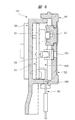
本発明の実施の形態2における動力作業機を、図8を参照して説明する。図8と図1とを比べると、電動作業機10の制御ユニット130の配置位置が異なる。図8に示す電動作業機10は、図2の制御回路を用いる。図8に示す制御ユニット130は、軸線B1に沿った方向でブラシレスモータ30と底部カバー17との間に配置されている。図3に示すカバー160は、図8では設けられていない。また、制御基板71は、電動作業機10の正面視で、軸線B1に対して交差する方向に配置されている。底部カバー17の内面に凹部164が設けられており、凹部164に基板ケース82が配置されている。プレート部83が凹部164の底面に接触している。
(Embodiment 2)
The power working machine in Embodiment 2 of this invention is demonstrated with reference to FIG. 8 and FIG. 1 are different in the arrangement position of the control unit 130 of the electric working machine 10. The electric working machine 10 shown in FIG. 8 uses the control circuit of FIG. The control unit 130 shown in FIG. 8 is disposed between the brushless motor 30 and the bottom cover 17 in a direction along the axis B1. The cover 160 shown in FIG. 3 is not provided in FIG. Further, the control board 71 is arranged in a direction intersecting the axis B1 when the electric work machine 10 is viewed from the front. A recess 164 is provided on the inner surface of the bottom cover 17, and the substrate case 82 is disposed in the recess 164. The plate portion 83 is in contact with the bottom surface of the recess 164.

そして、凹部164の内周面と側壁84との間に、弾性体165,166が設けられている。弾性体165,166は、軸線A1に沿った方向で異なる位置に配置されている。弾性体165,166は、軸線A1に沿った方向で基板ケース82の両側に配置されている。弾性体165,166は、基板ケース82と底部カバー17との間に介在されている。弾性体165,166は、弾性体152,153,154と同じ材質である。弾性体165,166は、基板ケース82に固定されていてもよいし、凹部164の内周面に固定されていてもよい。また、弾性体をプレート部83と凹部164との間に設けてもよく、この場合には、出力軸33に沿った方向の振動が、基板ケース82を介して制御基板71に伝達されることを抑制できる。   Elastic bodies 165 and 166 are provided between the inner peripheral surface of the recess 164 and the side wall 84. The elastic bodies 165 and 166 are arranged at different positions in the direction along the axis A1. The elastic bodies 165 and 166 are disposed on both sides of the substrate case 82 in the direction along the axis A1. The elastic bodies 165 and 166 are interposed between the substrate case 82 and the bottom cover 17. The elastic bodies 165 and 166 are made of the same material as the elastic bodies 152, 153 and 154. The elastic bodies 165 and 166 may be fixed to the substrate case 82 or may be fixed to the inner peripheral surface of the recess 164. Further, an elastic body may be provided between the plate portion 83 and the concave portion 164. In this case, vibration in the direction along the output shaft 33 is transmitted to the control board 71 via the board case 82. Can be suppressed.

また、図8においては、接続基板47がステータ31に固定されている。接続基板47に設けられた磁気センサS1〜S3は、ロータ32の永久磁石32bが発生する磁力を検出して信号を出力する。図8において、制御基板71と信号線75とを、図5に示したコネクタ、熱収縮チューブ、保護チューブを用いて接続することも可能である。   Further, in FIG. 8, the connection substrate 47 is fixed to the stator 31. The magnetic sensors S1 to S3 provided on the connection board 47 detect the magnetic force generated by the permanent magnet 32b of the rotor 32 and output a signal. In FIG. 8, it is also possible to connect the control board 71 and the signal line 75 using the connector, the heat shrinkable tube, and the protective tube shown in FIG.

図8の電動作業機10は、打撃作業が行われて作業機本体12が軸線B1と直角な方向、つまり、図1の軸線A1に沿った方向に振動すると、その振動は弾性体165,166により低減される。このため、制御ユニット130が、図1の軸線A1に沿った方向に振動することを抑制できる。さらに、図8に示す基板ケース82内に、図3の樹脂層200と同様の樹脂層を形成してもよい。したがって、実施の形態2の電動作業機10は、実施の形態1の電動作業機10と同様の効果を得られる。また、弾性体165,166が、本発明の弾性体に相当し、底部カバー17が本発明のハウジングに相当する。   In the electric working machine 10 shown in FIG. 8, when the hitting work is performed and the working machine body 12 vibrates in the direction perpendicular to the axis B1, that is, the direction along the axis A1 in FIG. Is reduced. For this reason, it can suppress that the control unit 130 vibrates in the direction along axis A1 of FIG. Furthermore, a resin layer similar to the resin layer 200 of FIG. 3 may be formed in the substrate case 82 shown in FIG. Therefore, the electric working machine 10 of the second embodiment can obtain the same effects as the electric working machine 10 of the first embodiment. The elastic bodies 165 and 166 correspond to the elastic body of the present invention, and the bottom cover 17 corresponds to the housing of the present invention.

本発明は前記実施の形態に限定されるものではなく、その要旨を逸脱しない範囲で種々変更可能である。例えば、振動抑制機構としての弾性体は、それぞれ別々に設けられていてもよいし、全体が一体化されていてもよい。本発明における弾性体は、振動を低減する緩衝材である。また、振動抑制機構としての弾性体は、基板ケースとモータハウジングとの間、及び基板ケースと中間ケースとの間に介在されていればよい。つまり、弾性体は、モータハウジング及び中間ケースのカバーに固定されていてもよい。そして、基板ケースがモータハウジングに固定されると、モータハウジングに固定されている弾性体が、基板ケースに接触する。また、中間ケースをモータハウジングに固定すると、中間ケースに設けた弾性体が基板ケースに接触する。   The present invention is not limited to the above-described embodiment, and various modifications can be made without departing from the scope of the invention. For example, the elastic bodies as the vibration suppressing mechanism may be provided separately or may be integrated as a whole. The elastic body in the present invention is a cushioning material that reduces vibration. Further, the elastic body as the vibration suppressing mechanism may be interposed between the substrate case and the motor housing and between the substrate case and the intermediate case. That is, the elastic body may be fixed to the motor housing and the cover of the intermediate case. When the substrate case is fixed to the motor housing, the elastic body fixed to the motor housing contacts the substrate case. When the intermediate case is fixed to the motor housing, the elastic body provided in the intermediate case comes into contact with the substrate case.

また、本発明の電動作業機は、商用電源、つまり、交流電源からブラシレスモータに電力が供給される。これに対して、本発明の電動作業機は、直流電源としての電池パックが作業機本体に取り付けられ、その電池パックの電力をブラシレスモータに供給する電動作業機を含む。本発明の電動作業機は、電動モータの動力で先端工具を動作させるものであればよい。   In the electric working machine of the present invention, power is supplied to the brushless motor from a commercial power source, that is, an AC power source. On the other hand, the electric working machine of the present invention includes an electric working machine in which a battery pack as a DC power source is attached to the working machine main body and the electric power of the battery pack is supplied to the brushless motor. The electric working machine of the present invention only needs to operate the tip tool with the power of the electric motor.

本発明の電動作業機は、先端工具に回転力及び軸線方向の打撃力を加えるハンマドリル及びハンマドライバを含む。本発明の電動作業機は、先端工具に回転力及び回転方向の打撃力を加えるインパクトドライバ、インパクトドリルを含む。さらに、電動作業機は、先端工具に回転力のみを加えるドライバ、ドリル、グラインダ、サンダを含む。本発明の電動作業機は、先端工具に軸線方向の打撃力のみを加えるハンマ、釘打ち機を含む。本発明の電動作業機は、先端工具を往復運動させるジグソー、セーバソーを含む。作業工具は、対象物を破砕する工具の他、ねじ部材を締め付けたり緩めたりするドライバビット、対象物を切断する鋸刃を含む。また、動力源としての電動モータは、ブラシレスモータの他、誘導電動機を含む。また、動力源としてのモータは、電動モータの他、油圧モータ、空気圧モータを含む。動力変換機構は、クランク機構の他、カム機構を含む。   The electric working machine of the present invention includes a hammer drill and a hammer driver that apply rotational force and axial striking force to the tip tool. The electric working machine of the present invention includes an impact driver and an impact drill that apply a rotational force and a striking force in the rotational direction to the tip tool. Furthermore, the electric working machine includes a driver, a drill, a grinder, and a sander that apply only a rotational force to the tip tool. The electric working machine of the present invention includes a hammer and a nailing machine that applies only an axial striking force to the tip tool. The electric working machine of the present invention includes a jigsaw and a saver saw that reciprocate the tip tool. The work tool includes a tool for crushing an object, a driver bit for tightening or loosening a screw member, and a saw blade for cutting the object. The electric motor as a power source includes an induction motor in addition to a brushless motor. Motors as power sources include hydraulic motors and pneumatic motors in addition to electric motors. The power conversion mechanism includes a cam mechanism in addition to the crank mechanism.

10…電動作業機、11…先端工具、12…作業機本体、14…中間ケース、17…底部カバー、20…モータハウジング、21…中間打撃子、22…打撃子、23…ピストン、30…ブラシレスモータ、33…出力軸、71…制御基板、82…基板ケース、83…プレート部、82a…ボス部、84…側壁、152,153,154,165,166…弾性体、A1,B1…軸線。   DESCRIPTION OF SYMBOLS 10 ... Electric working machine, 11 ... Tip tool, 12 ... Working machine main body, 14 ... Intermediate case, 17 ... Bottom cover, 20 ... Motor housing, 21 ... Intermediate striker, 22 ... Strike child, 23 ... Piston, 30 ... Brushless Motor 33, output shaft 71, control board 82, substrate case, 83 plate section 82 a boss section 84 side wall 152 153 154 165 166 elastic body A 1 B 1 axis

Claims (12)

モータの動力で第1軸線に沿った方向に作業工具を動作させる動力作業機であって、
前記モータを制御する制御基板と、
前記制御基板を収容する基板ケースと、
前記基板ケースを支持するハウジングと、
前記基板ケースと前記ハウジングとの間に介在させた弾性体と、
を有し、
前記ハウジングは、
前記モータを収容した第1ハウジングと、
前記第1ハウジングに固定され前記基板ケースを収容した第2ハウジングと、
を備え、
前記基板ケースは、
前記第1軸線と交差する第2軸線に沿った方向に延びるプレート部と、
前記プレート部の外周縁に設けられ、前記プレート部から前記第1軸線に沿った方向に延びる側壁と、
を備え、
前記弾性体は、前記第1軸線に沿った方向で、前記プレート部と前記第1ハウジングとの間、及び/または、前記側壁と前記第2ハウジングとの間に介在されている、動力作業機。
A power working machine that operates a work tool in a direction along the first axis with the power of a motor,
A control board for controlling the motor;
A substrate case for accommodating the control substrate;
A housing for supporting the substrate case;
An elastic body interposed between the substrate case and the housing;
Have
The housing is
A first housing containing the motor;
A second housing fixed to the first housing and containing the substrate case;
With
The substrate case is
A plate portion extending in a direction along a second axis intersecting the first axis;
A side wall provided on an outer peripheral edge of the plate portion and extending in a direction along the first axis from the plate portion;
With
The elastic working machine is interposed between the plate portion and the first housing and / or between the side wall and the second housing in a direction along the first axis. .
前記基板ケース内に、前記制御基板を覆う樹脂層が形成されている、請求項1に記載の動力作業機。   The power working machine according to claim 1, wherein a resin layer that covers the control board is formed in the board case. 前記基板ケースは、前記モータの出力軸の径方向で前記モータの側方で前記第1ハウジングの外部に配置されている、請求項1または2に記載の動力作業機。 The power work machine according to claim 1 or 2, wherein the substrate case is disposed outside the first housing at a side of the motor in a radial direction of the output shaft of the motor. 前記モータの動力で前記第1軸線に沿った方向に動作し、かつ、前記作業工具に打撃力を加える打撃機構が、前記ハウジングに設けられている、請求項1乃至3のいずれか1項に記載の動力作業機。 Operates in a direction along the first axis in the power of the motor and the striking mechanism for applying a striking force to the working tool, the are al provided in the housing, any one of claims 1 to 3 Power working machine as described in. 前記弾性体は、前記第1軸線に沿った方向で前記プレート部と前記第1ハウジングとの間、及び、前記側壁と前記第2ハウジングとの間に配置されている、請求項1乃至4のいずれか1項に記載の動力作業機。 The elastic body is disposed between the plate portion and the first housing and between the side wall and the second housing in a direction along the first axis . The power work machine of any one of Claims . 前記第1軸線を含む正面視で、前記第1軸線と、前記モータの出力軸の回転中心である前記第2軸線と、が交差して配置されている、請求項5に記載の動力作業機。 In front view including said first axis, said first axis, said second axis as the rotational axis of the output shaft of the motor, are arranged to cross, the power working machine according to claim 5 . 前記弾性体は、前記第1軸線に沿った方向で、
前記プレート部と前記第1ハウジングとの間に介在された第1弾性体と、
前記側壁の先端と前記第2ハウジングとの間に介在された第2弾性体と、
を有する、請求項1に記載の動力作業機。
The elastic body is in a direction along the first axis,
A first elastic body interposed between the plate portion and the first housing;
A second elastic body interposed between the tip of the side wall and the second housing;
The power working machine according to claim 1, comprising:
前記第1弾性体は、前記プレート部の外面の全域に設けられている、請求項7に記載の動力作業機。   The power working machine according to claim 7, wherein the first elastic body is provided over the entire outer surface of the plate portion. モータの動力で作業工具を動作させる動力作業機であって、
前記モータを制御する制御基板と、
前記制御基板を収容する基板ケースと、
前記基板ケースを支持するハウジングと、
前記基板ケースと前記ハウジングとの間に介在させた弾性体と、
を有し、
前記ハウジングは、前記モータを収容した第1ハウジングを備え、
前記基板ケースは、前記第1ハウジングに固定するためにねじ部材が挿入されるボス部を備え、
前記弾性体は、前記ボス部と前記基板ケースとの間に介在された第3弾性体を有する動力作業機。
A power working machine that operates a work tool with the power of a motor,
A control board for controlling the motor;
A substrate case for accommodating the control substrate;
A housing for supporting the substrate case;
An elastic body interposed between the substrate case and the housing;
Have
The housing includes a first housing that houses the motor,
The substrate case includes a boss portion into which a screw member is inserted for fixing to the first housing,
The elastic working machine is a power working machine having a third elastic body interposed between the boss portion and the substrate case.
モータの動力で作業工具を動作させる動力作業機であって、
前記モータを制御する制御基板と、
前記制御基板を収容する基板ケースと、
前記基板ケースを支持するハウジングと、
前記基板ケースと前記ハウジングとの間に介在させた弾性体と、
を有し、
前記ハウジングは、前記モータを収容した第1ハウジングを備え、
前記基板ケースは、前記第1ハウジングに固定するためにねじ部材が挿入されるボス部を備え、
前記弾性体は、前記ボス部に設けられた第3弾性体を有する動力作業機。
A power working machine that operates a work tool with the power of a motor,
A control board for controlling the motor;
A substrate case for accommodating the control substrate;
A housing for supporting the substrate case;
An elastic body interposed between the substrate case and the housing;
Have
The housing includes a first housing that houses the motor,
The substrate case includes a boss portion into which a screw member is inserted for fixing to the first housing,
The elastic body is a power working machine having a third elastic body provided at the boss portion .
前記基板ケースは、前記第1ハウジングに固定するためにねじ部材が挿入されるボス部を備え、
前記弾性体は、前記ボス部と前記ねじ部材との間に介在された第3弾性体を有する、請求項1に記載の動力作業機。
The substrate case includes a boss portion into which a screw member is inserted for fixing to the first housing,
The power working machine according to claim 1 , wherein the elastic body has a third elastic body interposed between the boss portion and the screw member .
前記ハウジングは、前記第1ハウジングに固定され前記基板ケースを収容した第2ハウジングを備え、
前記弾性体は、前記基板ケースと前記第1ハウジングとの間、及び/または、前記基板ケースと前記第2ハウジングとの間に介在されている、請求項10に記載の動力作業機。
The housing includes a second housing fixed to the first housing and containing the substrate case,
The power working machine according to claim 10, wherein the elastic body is interposed between the substrate case and the first housing and / or between the substrate case and the second housing .
JP2014220309A 2014-10-29 2014-10-29 Power working machine Active JP6439382B2 (en)

Priority Applications (5)

Application Number Priority Date Filing Date Title
JP2014220309A JP6439382B2 (en) 2014-10-29 2014-10-29 Power working machine
CN201580057419.3A CN107148327B (en) 2014-10-29 2015-10-21 Power working machine
EP15854049.2A EP3213877B1 (en) 2014-10-29 2015-10-21 Powered working machine
US15/522,294 US20170312902A1 (en) 2014-10-29 2015-10-21 Powered working machine
PCT/JP2015/079711 WO2016067997A1 (en) 2014-10-29 2015-10-21 Powered working machine

Applications Claiming Priority (1)

Application Number Priority Date Filing Date Title
JP2014220309A JP6439382B2 (en) 2014-10-29 2014-10-29 Power working machine

Publications (3)

Publication Number Publication Date
JP2016087696A JP2016087696A (en) 2016-05-23
JP2016087696A5 JP2016087696A5 (en) 2017-10-05
JP6439382B2 true JP6439382B2 (en) 2018-12-19

Family

ID=56015852

Family Applications (1)

Application Number Title Priority Date Filing Date
JP2014220309A Active JP6439382B2 (en) 2014-10-29 2014-10-29 Power working machine

Country Status (1)

Country Link
JP (1) JP6439382B2 (en)

Families Citing this family (3)

* Cited by examiner, † Cited by third party
Publication number Priority date Publication date Assignee Title
US20190275658A1 (en) * 2018-03-09 2019-09-12 Snap-On Incorporated Handle Support Module
JP7434721B2 (en) * 2018-04-27 2024-02-21 工機ホールディングス株式会社 Electric tool
JP2021053737A (en) * 2019-09-30 2021-04-08 工機ホールディングス株式会社 Power tool

Family Cites Families (5)

* Cited by examiner, † Cited by third party
Publication number Priority date Publication date Assignee Title
JPS57189789U (en) * 1981-05-26 1982-12-01
JP2005169533A (en) * 2003-12-09 2005-06-30 Matsushita Electric Works Ltd Rotating tool
JP4981345B2 (en) * 2006-04-18 2012-07-18 株式会社マキタ Electric tool
DE102008063113A1 (en) * 2008-01-09 2009-07-16 Marquardt Gmbh power tool
JP5534562B2 (en) * 2010-07-14 2014-07-02 日立工機株式会社 Electric tool

Also Published As

Publication number Publication date
JP2016087696A (en) 2016-05-23

Similar Documents

Publication Publication Date Title
WO2016067997A1 (en) Powered working machine
CN106573369B (en) Electric working machine
US10618157B2 (en) Power-actuated tool
JP5472683B2 (en) Electric tool
JP5333719B2 (en) Electric tool
AU2014368261A1 (en) Power-actuated tool
CN107073698B (en) Electric working machine
US11418094B2 (en) Electric tool
JP6439382B2 (en) Power working machine
JP2016087703A (en) Power work machine
JP2010207992A (en) Power tool
JP2016087702A (en) Electric power tool
JP2015120208A (en) Electric tool
US20220247279A1 (en) Electric powered work machine
WO2020085322A1 (en) Electric working machine
JP2012228136A (en) Brushless motor, air compressor with brushless motor, and electric power tool with brushless motor
JP2016175163A (en) Electric power tool
JP5505746B2 (en) Electric tool
JP6318603B2 (en) Impact tool
CN116317373A (en) Electric working machine
JP5083614B2 (en) Electric tool
JP2020054177A (en) Electrically-driven work machine

Legal Events

Date Code Title Description
A521 Written amendment

Free format text: JAPANESE INTERMEDIATE CODE: A523

Effective date: 20170825

A621 Written request for application examination

Free format text: JAPANESE INTERMEDIATE CODE: A621

Effective date: 20170825

A131 Notification of reasons for refusal

Free format text: JAPANESE INTERMEDIATE CODE: A131

Effective date: 20180710

A521 Written amendment

Free format text: JAPANESE INTERMEDIATE CODE: A523

Effective date: 20180831

TRDD Decision of grant or rejection written
A01 Written decision to grant a patent or to grant a registration (utility model)

Free format text: JAPANESE INTERMEDIATE CODE: A01

Effective date: 20181023

A61 First payment of annual fees (during grant procedure)

Free format text: JAPANESE INTERMEDIATE CODE: A61

Effective date: 20181105

R150 Certificate of patent or registration of utility model

Ref document number: 6439382

Country of ref document: JP

Free format text: JAPANESE INTERMEDIATE CODE: R150