JP2010207992A - Power tool - Google Patents
Power tool Download PDFInfo
- Publication number
- JP2010207992A JP2010207992A JP2009058785A JP2009058785A JP2010207992A JP 2010207992 A JP2010207992 A JP 2010207992A JP 2009058785 A JP2009058785 A JP 2009058785A JP 2009058785 A JP2009058785 A JP 2009058785A JP 2010207992 A JP2010207992 A JP 2010207992A
- Authority
- JP
- Japan
- Prior art keywords
- motor
- housing
- switching element
- heat radiating
- radiating member
- Prior art date
- Legal status (The legal status is an assumption and is not a legal conclusion. Google has not performed a legal analysis and makes no representation as to the accuracy of the status listed.)
- Granted
Links
Images


Classifications
-
- B—PERFORMING OPERATIONS; TRANSPORTING
- B25—HAND TOOLS; PORTABLE POWER-DRIVEN TOOLS; MANIPULATORS
- B25F—COMBINATION OR MULTI-PURPOSE TOOLS NOT OTHERWISE PROVIDED FOR; DETAILS OR COMPONENTS OF PORTABLE POWER-DRIVEN TOOLS NOT PARTICULARLY RELATED TO THE OPERATIONS PERFORMED AND NOT OTHERWISE PROVIDED FOR
- B25F5/00—Details or components of portable power-driven tools not particularly related to the operations performed and not otherwise provided for
- B25F5/008—Cooling means
Abstract
Description
本発明は、電動モータを用いた電動工具に関し、特に電動モータの駆動等に用いられる半導体素子の放熱性を向上させた電動工具に関する。 The present invention relates to an electric tool using an electric motor, and more particularly to an electric tool with improved heat dissipation of a semiconductor element used for driving an electric motor.
近年、ドリルやドライバ等の先端工具をモータによって回転駆動して所要の作業を行う電動工具において、ブラシレスモータが使われるようになってきた。ブラシレスモータは、例えばブラシ(整流用刷子)の無いDC(直流)モータであり、コイル(巻線)を固定子側に、永久磁石を回転子側に用い、インバータで駆動された電力を所定のコイルへ順次通電することによりロータを回転させる。インバータ回路を構成する半導体素子はFET(電界効果トランジスタ)や、IGBT(絶縁ゲートバイポーラトランジスタ)のような大容量の出力トランジスタを使用し大電流で駆動するため、放熱性を良くしなければならない。そのため、特許文献1では、ステータに巻装されたコイルへの通電をオン・オフさせるためのスイッチング素子を、モータの後方の回路基板上に配置し、モータ用の冷却風を利用して放熱する方法が用いられる。
In recent years, brushless motors have come to be used in electric tools that perform necessary work by rotationally driving a tip tool such as a drill or a driver with a motor. The brushless motor is, for example, a DC (direct current) motor without a brush (rectifying brush), and uses a coil (winding) on the stator side and a permanent magnet on the rotor side, and the electric power driven by the inverter is predetermined. The rotor is rotated by sequentially energizing the coils. The semiconductor element constituting the inverter circuit uses a large-capacity output transistor such as an FET (Field Effect Transistor) or an IGBT (Insulated Gate Bipolar Transistor) and is driven with a large current. Therefore, heat dissipation must be improved. For this reason, in
スイッチング素子をモータ後方の回路基板に搭載する方法では、冷却と搭載スペースの関係から、スイッチング素子の高さ方向がモータの回転軸と平行になるように配置していた。しかし、そのような配置をすると冷却の面では良好な性能を実現できるが、モータの軸方向後側に、回路基板とスイッチング素子の高さ分のスペースが必要となる。そのため、ブラシレスモータを電動工具に適用するとハウジングの胴体部(又はモータ収容部)の前後方向の長さが長くなってしまう。 In the method of mounting the switching element on the circuit board behind the motor, the switching element is arranged so that the height direction of the switching element is parallel to the rotation axis of the motor from the relationship between cooling and mounting space. However, with such an arrangement, good performance can be realized in terms of cooling, but a space corresponding to the height of the circuit board and the switching element is required on the rear side in the axial direction of the motor. Therefore, when the brushless motor is applied to an electric tool, the length of the body part (or motor housing part) of the housing in the front-rear direction becomes long.
ハウジングの前後方向の長さの増大を防ぐため、回路基板をモータの後ろ側でなく別の位置に設けるということも考えられる。しかしながら、モータのコイルとスイッチング素子をつなぐ配線が長くなってしまうばかりか、熱を発しやすいスイッチング素子の放熱上の制約から、モータ後方以外の他の場所に基板を配置することが難しかった。 In order to prevent an increase in the length of the housing in the front-rear direction, it is conceivable that the circuit board is provided at another position instead of the rear side of the motor. However, not only the wiring connecting the motor coil and the switching element becomes long, but also it is difficult to dispose the substrate in a place other than the rear of the motor due to the heat dissipation restriction of the switching element that easily generates heat.
本発明は上記背景に鑑みてなされたもので、その目的はモータ用のスイッチング素子の取付位置を変更すると共に、その冷却方法を改良した電動工具を提供することにある。 The present invention has been made in view of the above background, and an object of the present invention is to provide an electric tool in which the mounting position of a switching element for a motor is changed and the cooling method is improved.
本発明の別の目的は、ブラシレスモータを用いた電動工具において、ハウジングのモータを収容する部分の前後長を短くしてコンパクトに構成した電動工具を提供することにある。 Another object of the present invention is to provide a power tool that uses a brushless motor and is configured to be compact by shortening the front-rear length of the portion of the housing that houses the motor.
本願において開示される発明のうち、代表的なものの特徴を説明すれば、次の通りである。 Of the inventions disclosed in the present application, typical features will be described as follows.
本発明の一つ特徴によれば、モータと、モータを収容するハウジングと、モータの回転を駆動するスイッチング素子と、スイッチング素子を冷却するための放熱部材とを有する電動工具であって、放熱部材の一部をハウジングの外部に露出するようにした。ハウジングはモータと回転伝達手段を収容する胴体部と、胴体部から延びるグリップ部と、グリップ部の先端のバッテリ保持部を含んで構成し、モータの回転を駆動するスイッチング素子が、グリップ部又はバッテリ保持部内に設けられる基板上に配置され、放熱部材の一部が、グリップ部又はバッテリ保持部の外部に露出するように構成した。 According to one aspect of the present invention, there is provided a power tool having a motor, a housing that houses the motor, a switching element that drives rotation of the motor, and a heat dissipation member that cools the switching element. A part of was exposed to the outside of the housing. The housing includes a body portion that accommodates the motor and the rotation transmission means, a grip portion that extends from the body portion, and a battery holding portion at the tip of the grip portion, and the switching element that drives the rotation of the motor serves as the grip portion or the battery. It arrange | positioned on the board | substrate provided in a holding | maintenance part, and it comprised so that a part of heat radiating member might be exposed to the exterior of a grip part or a battery holding | maintenance part.
本発明の他の特徴によれば、放熱部材は、スイッチング素子の放熱部と接触するように取り付けられ、金属部材により構成される。複数のスイッチング素子は基板に取り付けられ、放熱部材はこれらスイッチング素子全体を覆うように構成すると好ましい。また、放熱部材と基板によって、スイッチング素子を収容する密閉空間を形成するように構成すると好ましい。 According to the other characteristic of this invention, a heat radiating member is attached so that it may contact with the heat radiating part of a switching element, and is comprised with a metal member. Preferably, the plurality of switching elements are attached to the substrate, and the heat dissipation member is configured to cover the entire switching elements. Further, it is preferable that a sealed space for accommodating the switching element is formed by the heat dissipation member and the substrate.
本発明のさらに他の特徴によれば、放熱部材は、ハウジングの左右2箇所において外部に露出するように構成した。ハウジングには、内部から外部に貫通する貫通穴が設けられ、貫通穴の形状に対応する放熱部材の突出部が、貫通穴内に位置するように取り付けられる。この貫通穴は、ハウジングの左右2箇所においてそれぞれ複数個ずつ設けても良い。 According to still another feature of the present invention, the heat radiating member is configured to be exposed to the outside at two left and right positions of the housing. The housing is provided with a through hole penetrating from the inside to the outside, and the protrusion of the heat radiating member corresponding to the shape of the through hole is attached so as to be located in the through hole. A plurality of through holes may be provided at two locations on the left and right sides of the housing.
請求項1の発明によれば、モータの回転を駆動するスイッチング素子を冷却するための放熱部材を設け、この放熱部材の一部がハウジングの外部に露出するので、放熱部材が外気に当たりやすくなり、スイッチング素子を効果的に冷却できる。また、スイッチング素子の搭載位置の自由度が向上し、ハウジング内の任意の箇所にスイッチング素子を搭載する回路基板を設けることができる。 According to the first aspect of the present invention, the heat dissipating member for cooling the switching element that drives the rotation of the motor is provided, and a part of the heat dissipating member is exposed to the outside of the housing. The switching element can be effectively cooled. Further, the degree of freedom of the mounting position of the switching element is improved, and a circuit board on which the switching element is mounted can be provided at an arbitrary position in the housing.
請求項2の発明によれば、スイッチング素子がグリップ部又はバッテリ保持部内に設けられる基板上に配置されるので、ハウジングの胴体部の前後長を延ばすことなく、スイッチング素子をハウジング内に設けることができる。また、搭載した基板上のスイッチング素子を効果的に冷却することができる。
According to the invention of
請求項3の発明によれば、放熱部材はスイッチング素子の放熱部と接触するように取り付けられ、金属部材により構成されるので良好な放熱効果を達成できると共に、放熱部材を安価に製造することができる。
According to the invention of
請求項4の発明によれば、スイッチング素子は基板に取り付けられ、放熱部材はこれらスイッチング素子全体を覆うので、ゴミ、埃による基板上の搭載素子への影響を防止することができる。
According to the invention of
請求項5の発明によれば、放熱部材と基板によって、スイッチング素子を収容する密閉空間を形成するので、ゴミ、埃だけでなく水分による基板上の搭載素子への影響も防止できる。
According to the invention of
請求項6の発明によれば、放熱部材は、ハウジングの左右2箇所において外部に露出するので、効果的な放熱効果を達成することができる。
According to invention of
請求項7の発明によれば、ハウジングには、内部から外部に貫通する貫通穴が設けられ、貫通穴の形状に対応する放熱部材の突出部が、貫通穴内に位置するように取り付けられるので、使用者が熱くなった放熱部材を触ってしまうことによる不快感を防止することができる。 According to the invention of claim 7, the housing is provided with a through hole penetrating from the inside to the outside, and the protruding portion of the heat dissipation member corresponding to the shape of the through hole is attached so as to be located in the through hole. It is possible to prevent discomfort caused by the user touching the heat radiating member.
請求項8の発明によれば、貫通穴は、ハウジングの左右2箇所においてそれぞれ複数設けられるので、個々の貫通穴の大きさを小さくすることができ、貫通穴に指を入れることによって放熱部材を直接触ってしまうことを回避することができる。 According to the eighth aspect of the present invention, since a plurality of through holes are provided at two positions on the left and right sides of the housing, the size of each through hole can be reduced. Direct contact can be avoided.
請求項9の発明によれば、ハウジングに貫通穴を設け、放熱部材を貫通穴まで延ばしたので放熱部材の一部が外気に曝されるので、効果的にスイッチング素子を冷却できる。
According to the invention of
本発明の上記及び他の目的ならびに新規な特徴は、以下の明細書の記載及び図面から明らかになるであろう。 The above and other objects and novel features of the present invention will become apparent from the following description and drawings.
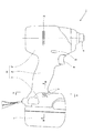
以下、本発明の実施例を図1〜3に基づいて説明する。尚、以下の説明において、上下、前後の方向は、図1に示した方向として説明する。図1は本発明に係る電動工具の一実施例としてのインパクトドライバ1の内部構造を示す図である。インパクトドライバ1は、充電可能なバッテリ2を電源とし、モータ3を駆動源として回転打撃機構4を駆動し、出力軸であるアンビル5に回転と打撃を与えることによってドライバビット等の図示しない先端工具に回転打撃力を間欠的に伝達してネジ締めやボルト締め等の作業を行う。
Embodiments of the present invention will be described below with reference to FIGS. In the following description, the vertical and forward / backward directions will be described as the directions shown in FIG. FIG. 1 is a view showing an internal structure of an
モータ3は、ブラシレスDCモータであって、側面から見て略T字状の形状を成すハウジング6の筒状の胴体部6a内に収容される。ハウジング6は、ほぼ対称な形状の左右2つの部材に分割可能に構成され、それら部材が複数のネジにより固定される。そのため、分割されるハウジング6の一方(本実施例では左側ハウジング)に複数のネジボス20が形成される。モータ3の回転軸19は、胴体部6aの後端側のベアリング17aと中央部付近に設けられるベアリング17bによって回転可能に保持される。モータ3の後方には回転子3bの位置を検出するための回転位置検出素子42を搭載する基板7が設けられ、この基板7にモータ3のステータコイルが接続される。
The
ハウジング6の胴体部6aから略直角に一体に延びるグリップ部6b内の上部にはトリガスイッチ8及び正逆切替レバー44が設けられ、トリガスイッチ8には図示しないバネによって付勢されてグリップ部6bから突出するトリガ操作部8aが設けられる。グリップ部6b内の下方には、トリガ操作部8aによってモータ3の速度を制御する機能等を備えた制御回路基板9が収容される。この制御回路基板9には、さらに6つのスイッチング素子21が搭載され、これらスイッチング素子21によってインバータ制御を行うことによりモータ3を回転させる。グリップ部6bの下方に形成されたバッテリ保持部6cには、ニッケル水素やリチウムイオン等のバッテリ2が着脱可能に装着される。
A trigger switch 8 and a forward /
モータ3の前方には、回転軸19に取り付けられてモータ3と同期して回転するファン18が設けられる。ファン18により、胴体部6aの後方の空気取入口25から空気が後方から前方に吸引される。吸引された空気は、ハウジング6の胴体部6aであってファン18の半径方向外周側付近に形成される複数のスリット23(図2)からハウジング6の外部に排出される。また、図1において、空気取入口25はハウジング6の胴体部6a後方に形成されているが、これに加えて、ハウジング6の基板7の周囲の領域に形成しても良い。
A
回転打撃機構4は、遊星歯車減速機構10とスピンドル11とハンマ12を備え、トリガスイッチ8のトリガ操作部8aが引かれてモータ3が起動されると、モータ3の回転は遊星歯車減速機構10によって減速されてスピンドル11に伝達され、スピンドル11が所定の速度で回転駆動される。ここで、スピンドル11とハンマ12とはカム機構によって連結され、このカム機構は、スピンドル11の外周面に形成されたV字状のスピンドルカム溝11aと、ハンマ12の内周面に形成されたハンマカム溝12aと、これらのカム溝11a、12aに係合するボール13によって構成される。
The
ハンマ12は、スプリング14によって常に前方に付勢されており、静止時にはボール13とカム溝11a、12aとの係合によってアンビル5の端面とは隙間を隔てた位置にある。そして、ハンマ12とアンビル5には図示しない凸部がそれぞれ対称的に形成される。アンビル5は、メタルベアリング16bにより回転可能に保持される。
The
スピンドル11が回転駆動されると、その回転はカム機構を介してハンマ12に伝達され、ハンマ12の凸部がアンビル5の凸部に係合してアンビル5を回転させる。そのときの反力によってスピンドル11とハンマ12との間に相対回転が生ずると、ハンマ12はカム機構のスピンドルカム溝11aに沿ってスプリング14を圧縮しながらモータ3側へと後退を始める。
When the
そして、ハンマ12の後退動によってハンマ12の凸部がアンビル5の凸部を乗り越えて両者の係合が解除されると、ハンマ12は、スピンドル11の回転力に加え、スプリング14に蓄積された弾性エネルギーとカム機構の作用によって回転方向及び前方に急速に加速されつつ、スプリング14の付勢力によって前方へ移動し、その凸部がアンビル5の凸部に再び係合して一体に回転し始める。このとき、強力な回転打撃力がアンビル5に加えられるため、アンビル5に装着された図示しない先端工具を介してネジに回転打撃力が伝達される。図示しない先端工具は、スリーブ15を軸方向前方に移動させることによりワンタッチで装着及び脱着が可能である。以後、同様の動作が繰り返されて先端工具からネジに回転打撃力が間欠的に繰り返し伝達され、例えば、ネジが木材等の図示しない被締結材にねじ込まれる。
When the protrusion of the
図2は、図1のインパクトドライバ1の外観を示す側面図である。ハウジング6は3つの部分(6a、6b、6c)から構成され、胴体部6aの、ファン18の半径方向外周側付近には冷却風の排出用の複数のスリット23が形成される。また、バッテリ保持部6cの側面には、後述する放熱部材22の一部を露出させるための貫通穴24が複数形成される。尚、図2の側面図から、ハウジング6の胴体部6aの後端部と、バッテリ2の後端部は、前後方向でみてほぼ同じ位置にあり、胴体部6aの前後長がコンパクトに形成されていることが理解できるであろう。
FIG. 2 is a side view showing the appearance of the
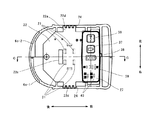
図3は、図2のA−A部の断面図であり、制御回路基板9の取付部付近を上から見た上面図である。図3において図示した左右方向は、使用者が右手でグリップ部6bを把持して作業姿勢で持ったときの、使用者から見た方向を右、左と定義している。制御回路基板9(図4参照)はハウジング6のグリップ部6bとバッテリ保持部6cの間に配置され、放熱部材22により全体が覆われているので、図3において制御回路基板9は見えない。制御回路基板9には、FET等の6つのスイッチング素子21が制御回路基板9に対して垂直方向に、即ち、スイッチング素子21の高さ方向が上下に配置されるように搭載され、このスイッチング素子21は、放熱部材22の下側に設けられる。尚、スイッチング素子21は、図3では直視できないため、その位置を点線で示している。
3 is a cross-sectional view taken along the line AA in FIG. 2, and is a top view of the vicinity of the mounting portion of the
放熱部材22は金属製の成型されたヒートシンク又は放熱フィン等であり、例えばアルミニウム、鉄等の金属の一体成型によって製造される。アルミニウムを用いることで軽量に構成でき、鉄を用いることによって安価に製造することができるが、いずれにしても成型性が良いので、グリップ部6b又はバッテリ保持部6c内の比較的小さな空間でも問題なく設置することができる。放熱部材22の左右側2箇所には、外側に延在する略長方形の延在部22aが形成され、この略長方形の一辺の一部が外部に露出し、外気と触れるように構成される。また、外部に露出する部分には、上からみて櫛状に凹凸部22dが形成される。ハウジング6には複数の四角い貫通穴(又はスリット)24が形成され、凹凸部22dがこの貫通穴24を塞ぐように配置されることにより、放熱部材22の一部が外部に露出することになる。
The
放熱部材22の凹凸部22dは、ハウジング6c−1及び6c−2の側面に設けられた貫通穴24にはめ込まれる。これにより、放熱部材22左右方向に延びる面と、電動工具の外枠を形成するハウジング6cの面はお互いが交差する関係となる。尚、凹凸部22dの最外位置は、ハウジング6cの内縁部(内壁面)よりも外側に突出することが重要である。さらに凹凸部22dの最外位置がハウジング6cの外縁部(外壁面)より突出するように構成しても良いが、外縁部(外壁面)から突出しないで僅かながら内側になるように構成すれば、使用者が放熱部材22に触れてしまって不快な思いをする恐れが無くなる。
The
制御回路基板9の上面前方側には、バッテリ保持部6cの上側に露出する制御パネル27が取り付けられる。制御パネル27には、各種の操作ボタンや表示ランプが搭載される。ライトボタン36は、インパクトドライバ1に取り付けられる白色LEDライト(図示せず)をON/OFFするためのスイッチである。電池残量ボタン37は電池の残量を確認するためのボタンであり、これを押すと、電池のマークを示す電池残量表示ランプ38において電池残量が「満充電(LEDが2つ点灯)」「約半分(LEDが1つ点灯)」「残量少(2つのLEDがいずれも点灯しない)」の3段階のいずれであるかを確認できる。
A
強弱表示ランプ39は、図示しない強弱切替スイッチにより設定された締め付けトルクの強さを示すランプであり、モータ3の回転数が4段階(例えば、2600、2000、1200、500回/分)のどれに設定されているかをLEDの点灯数により表示する。単発/連発表示ランプ40は、図示しない単発/連発切替スイッチを押すごとに切り替わる単発モードと連発モードのいずれかであるかを表示する。単発モードは、トリガ操作部8aを引いて打撃開始後、数回の打撃(1〜4回)で自動停止するモードであり、連発モードはトリガ操作部8aを引いて打撃を開始すると、連続打撃(自動停止せず)するモードである。
The
放熱板22の後方側には、制御回路基板9に取り付けられたコネクタを貫通させるための長方形の穴22cが形成される。このように本実施例では、スイッチング素子21をグリップ部6bの下方、又は、バッテリ保持部6c内に配置することにより、基板上の実装効率が向上する。また、スイッチング素子21に対して、ファン等によって強制的に発生される風が当たらなくても十分な冷却効果を達成することができる。
On the rear side of the
図4は、図2のB−B部の断面図であり、制御回路基板9の取付部付近を前方から見た断面図である。放熱部材22は、6つのスイッチング素子21を効果的に覆って、それらスイッチング素子21の放熱部(金属製の放熱板)と当接するように、上下方向に延びるリブ22eが形成される。放熱部材22の左右方向の端部には、凹凸部22dが位置し、この結果放熱部材22の一部がハウジング外部の外気に露出することになる。尚、ハウジング6c−1、6c−2の放熱部材22の凹凸部22dが露出する部分は、段差状に形成され、凹凸部22dは図4の鎖線28で示すハウジング6c−2の外縁よりも内側になるように配置される。この鎖線28で示す部分の上下方向の長さ(幅)は短いため、使用者が放熱部材22の凹凸部22dに直接触れてしまうことを効果的に防止できる。尚、放熱部材22の凹凸部22dの温度が、指で触れても問題のない程度にしか上昇しない場合は、凹凸部22dをハウジング6の外縁と同一面となるように構成するか、あるいは外部に突出するように構成しても良い。
4 is a cross-sectional view taken along the line BB in FIG. 2 and is a cross-sectional view of the vicinity of the mounting portion of the
また、ハウジング6c−1、6c−2を構成する2つの部材に設けられた貫通穴24と放熱部材22の凹凸部22dとが係合することにより、放熱部材22のハウジング6c内での位置決めを行うことができる。さらに、このようにハウジング6c−1、6c−2を構成する2つの部材により、放熱部材22を挟み込むように構成したので、ハウジング6の一方側(例えば6c−1)に放熱部材22を配置した状態で、他方側のハウジング(例えば6c−2)を合わせてネジ止めすることにより、電動工具を組み立てることができる。
Further, the through
図5は、図3のC−C部の断面図である。この図ではハウジング6の部分の図示は省略してある。放熱部材22のリブ22eは、6つのスイッチング素子21の放熱部に当接するように形成され、リブ22eの下端部は制御回路基板9に当接する。また、放熱部材22の前方側は制御パネル27に接続され、後方側は、ハウジング6cに形成されたネジボス26を覆うようにして下方向に折り返される折り返し部22hが形成される。このように放熱部材22で制御回路基板9全体を覆うことで防塵性や防水性に優れた構造とすることができる。FET等のスイッチング素子21は、ほぼ直方体の形状をしている。放熱部材22は、図5から明らかなように、その上方、前後、左右方向において、その直方体の5面で各スイッチング素子21を取り囲むように設けられる。このように、スイッチング素子21を取り囲むように放熱部材22を設けたので、スイッチング素子21の放熱効率を向上させることができる。
FIG. 5 is a cross-sectional view taken along the line CC in FIG. In this figure, the illustration of the portion of the
次に、モータ3の駆動制御系の構成と作用を図6に基づいて説明する。図6はモータの駆動制御系の構成を示すブロック図であり、本実施例では、モータ3は3相のブラシレスDCモータで構成される。このブラシレスDCモータは、いわゆるインナーロータ型であって、複数組(本実施例では2組)のN極とS極を含む永久磁石(マグネット)を含んで構成される回転子(ロータ)3bと、スター結線された3相の固定子巻線U、V、Wから成る固定子3aと、回転子3bの回転位置を検出するために周方向に所定の間隔毎、例えば角度60°毎に配置された3つの回転位置検出素子(ホール素子)42を有する。これら回転位置検出素子42からの位置検出信号に基づいて固定子巻線U、V、Wへの通電方向と時間が制御され、モータ3が回転する。回転位置検出素子42は、基板7上の回転子3bのマグネットに対向する位置に設けられる。
Next, the configuration and operation of the drive control system of the
制御回路基板9上に搭載される電子素子には、3相ブリッジ形式に接続されたFETなどの6個のスイッチング素子Q1〜Q6を含む。ブリッジ接続された6個のスイッチング素子Q1〜Q6の各ゲートは、制御回路基板9に搭載される制御信号出力回路46に接続され、6個のスイッチング素子Q1〜Q6の各ドレインまたは各ソースは、スター結線された固定子巻線U、V、Wに接続される。これによって、6個のスイッチング素子Q1〜Q6は、制御信号出力回路46から入力されたスイッチング素子駆動信号(H4、H5、H6等の駆動信号)によってスイッチング動作を行い、インバータ回路47に印加されるバッテリ2の直流電圧を3相(U相、V相及びW相)電圧Vu、Vv、Vwとして固定子巻線U、V、Wに電力を供給する。
The electronic elements mounted on the
6個のスイッチング素子Q1〜Q6の各ゲートを駆動するスイッチング素子駆動信号(3相信号)のうち、3個の負電源側スイッチング素子Q4、Q5、Q6をパルス幅変調信号(PWM信号)H4、H5、H6として供給し、制御回路基板9上に搭載された演算部41によって、トリガスイッチ8のトリガ操作部8aの操作量(ストローク)の検出信号に基づいてPWM信号のパルス幅(デューティ比)を変化させることによってモータ3への電力供給量を調整し、モータ3の起動/停止と回転速度を制御する。
Of the switching element drive signals (three-phase signals) for driving the gates of the six switching elements Q1 to Q6, the three negative power supply side switching elements Q4, Q5, Q6 are converted into pulse width modulation signals (PWM signals) H4, The pulse width (duty ratio) of the PWM signal is supplied as H5 and H6 and based on the detection signal of the operation amount (stroke) of the
ここで、PWM信号は、インバータ回路47の正電源側スイッチング素子Q1〜Q3または負電源側スイッチング素子Q4〜Q6の何れか一方に供給され、スイッチング素子Q1〜Q3またはスイッチング素子Q4〜Q6を高速スイッチングさせることによって結果的にバッテリ2の直流電圧から各固定子巻線U、V、Wに供給する電力を制御する。尚、本実施例では、負電源側スイッチング素子Q4〜Q6にPWM信号が供給されるため、PWM信号のパルス幅を制御することによって各固定子巻線U、V、Wに供給する電力を調整してモータ3の回転速度を制御することができる。
Here, the PWM signal is supplied to any one of the positive power supply side switching elements Q1 to Q3 or the negative power supply side switching elements Q4 to Q6 of the
インパクトドライバ1には、モータ3の回転方向を切り替えるための正逆切替レバー44が設けられ、回転方向設定回路50は正逆切替レバー44の変化を検出するごとに、モータの回転方向を切り替えて、その制御信号を演算部41に送信する。演算部41は、図示していないが、処理プログラムとデータに基づいて駆動信号を出力するための中央処理装置(CPU)、処理プログラムや制御データを記憶するためのROM、データを一時記憶するためのRAM、タイマ等を含んで構成される。
The
制御信号出力回路46は、回転方向設定回路50と回転子位置検出回路43の出力信号に基づいて所定のスイッチング素子Q1〜Q6を交互にスイッチングするための駆動信号を形成し、その駆動信号を制御信号出力回路46に出力する。これによって固定子巻線U、V、Wの所定の巻線に交互に通電し、回転子3bを設定された回転方向に回転させる。この場合、負電源側スイッチング素子Q4〜Q6に印加する駆動信号は、印加電圧設定回路49の出力制御信号に基づいてPWM変調信号として出力される。モータ3に供給される電流値は、電流検出回路48によって測定され、その値が演算部41にフィードバックされることにより、設定された駆動電力となるように調整される。尚、PWM信号は正電源側スイッチング素子Q1〜Q3に印加しても良い。
The control
以上、説明したように第1の実施例によれば、スイッチング素子21をモータの後端側に配置せずにハウジングのグリップ部或いはバッテリ保持部に配置したので、ハウジングの胴体部の前後長を短くして、全体をコンパクトに構成した電動工具を実現できる。また、スイッチング素子に放熱部材を設けて効果的に放熱することにより、ハウジングのグリップ部内に発熱の大きな半導体素子を搭載できるので、電動工具の小型化や設計の自由度を高めることができる。
As described above, according to the first embodiment, the switching
さらに、放熱部材22の一部を直接外気に触れる構造にすることで、電動ファン等によって冷却風を放熱部材22に当てるように構成しなくても十分な放熱を行うことが可能となり、安価な構成にて効果的な冷却機構を実現できる。
Furthermore, by adopting a structure in which a part of the
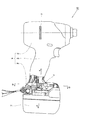
次に、図7〜図10を用いて本発明の第2の実施例を説明する。図7は、第2の実施例にかかるインパクトドライバ51の外観を示す側面図である。ハウジング56は3つの部分(56a、56b、56c)から構成され、胴体部56aの、ファンの半径方向外周側付近には冷却風の排出用の複数のスリット73が形成される点では、第1の実施例と同様である。制御回路基板59(図9参照)はハウジング56のグリップ部56bとバッテリ保持部56cの間に配置され、放熱部材72により全体が覆われる。バッテリ保持部56cの側面には、放熱部材72の一部を露出させるための後述する貫通穴74が複数形成される。
Next, a second embodiment of the present invention will be described with reference to FIGS. FIG. 7 is a side view showing an appearance of the
図8は、図7のD−D部の断面図であり、制御回路基板59の取付部付近を上から見た上面図である。制御回路基板59(図9参照)はハウジング56のグリップ部56bとバッテリ保持部56cの間に配置され、放熱部材72により全体が覆われる。制御回路基板59には、FET等の6つのスイッチング素子71が制御回路基板59に対して垂直方向に、即ち、スイッチング素子71の高さ方向が上下に配置されるように搭載され、このスイッチング素子71は、放熱部材72の下側に設けられる。尚、スイッチング素子71は、図8では直視できないため、その位置を点線で示している。
FIG. 8 is a cross-sectional view taken along the line DD in FIG. 7, and is a top view of the vicinity of the mounting portion of the
放熱部材72は金属製の成型品であって、材質等は第1の実施例と同じであるが、その形状が異なる。即ち、放熱部材72の左右側2箇所には、外側に延在する略長方形の延在部72aが形成され、さらに、後方側に略長方形の延在部72hが形成される。延在部72aの左右側の一辺には、上面視で櫛状に凹凸が形成され、ハウジング側には複数の四角い貫通穴74が形成され、凹凸部72dがこの貫通穴74を塞ぐように位置することにより、放熱部材72の一部が外部に露出する。同様に、延在部72hの後方の辺には、上面視で櫛状に凹凸部72gが形成される。ハウジング56には複数の四角い貫通穴(又はスリット)74が形成され、凹凸部72gがこの貫通穴78を塞ぐように位置することにより、放熱部材72の一部が外部に露出する。
The
制御回路基板59の上面前方側には、バッテリ保持部56cの上側に露出する制御パネル77が取り付けられる。制御パネル77には、各種の操作ボタンや表示ランプが搭載されるが、それらは図3で示した第1の実施例と同じであるので繰り返しの説明は省略する。
A
図9は、図7のE−E部の断面図であり、制御回路基板59の取付部付近を前方から見た断面図である。この図から理解できるように、放熱部材72は、スイッチング素子71の上方、前後、左右方向において、その直方体の5面で各スイッチング素子71を取り囲むように設けられるだけでなく、さらに延在して、延在部72gが制御回路基板59の上面と接触するように構成される。このように構成すれば、冷却性能をさらに向上させることができる。また、制御回路基板59の上面を放熱部材72により覆うようにしたので制御回路基板59の上面に水滴や粉塵が接触することが少なくなる。本実施例では、放熱部材72はプレス等の加工により一体成型で製造されるが、制御回路基板59の上面及び側面を覆う延在部72gと、その他の部分を別体部品として製造しても良い。また、その他の方法により放熱部材72を数個の別体部品から製造するように構成しても良い。
FIG. 9 is a cross-sectional view taken along line EE in FIG. 7, and is a cross-sectional view of the vicinity of the attachment portion of the
図10は、図8のF−F部の断面図である。この図ではハウジング56の部分の図示は省略してある。放熱部材72のリブ72eは、6つのスイッチング素子71の放熱部に当接するように形成され、リブ72eの下端部は制御回路基板59に当接する。また、放熱部材72の放熱部材72の前方側は制御パネル77に接続され、後方側は、ネジボス76を覆うようにして下方向に折り返される折り返し部72iが形成される。さらにこの部分の上端から後方側に延在する延在部72hが形成され、延在部72hの後端側に、ハウジング56の外部に露出する凹凸部72gが形成される。このように放熱部材72でスイッチング素子71及び制御回路基板59全体を覆うことで、放熱効率をより向上させることができると共に、防塵性や防水性に優れた構造とすることができる。
FIG. 10 is a cross-sectional view taken along the line FF in FIG. In this figure, the illustration of the portion of the
以上、本発明を示す実施例に基づき説明したが、本発明は上述の実施例に限定されるものではなく、その趣旨を逸脱しない範囲内で種々の変更が可能である。例えば、放熱部材の端部を凹凸形状とするだけでなく、ハウジングの外部に配置される放熱部材、金属製のネジなどを放熱部材に接続させることで外気に触れる表面積を大きくし、放熱部材の放熱効率を向上させることができる。 As described above, the present invention has been described based on the embodiments. However, the present invention is not limited to the above-described embodiments, and various modifications can be made without departing from the spirit of the present invention. For example, in addition to making the end portion of the heat radiating member uneven, the heat radiating member disposed outside the housing, a metal screw, etc. are connected to the heat radiating member to increase the surface area that touches the outside air, Heat dissipation efficiency can be improved.
尚、本実施例では電動工具の例としてインパクトドライバに対して適用した実施例を用いて説明したが、インパクトドライバに限られず、放熱の必要な半導体素子やスイッチング素子を用いた任意の電動工具に対しても同様に適用可能である。さらに、本実施例ではモータとしてブラシレスDCモータを用いた例を説明したが、これに限定されず、他の種類のモータであっても良い。 In addition, although the present Example demonstrated using the Example applied with respect to the impact driver as an example of an electric tool, it is not restricted to an impact driver, Arbitrary electric tools using the semiconductor element and switching element which require heat dissipation are used. The same applies to the same. Furthermore, although the example which used the brushless DC motor as a motor was demonstrated in the present Example, it is not limited to this, Other types of motors may be sufficient.
1 インパクトドライバ 2 バッテリ 3 モータ
3a (モータの)固定子 3b (モータの)回転子 4 回転打撃機構
5 アンビル 6 ハウジング 6a (ハウジングの)胴体部
6b (ハウジングの)グリップ部 6c (ハウジングの)バッテリ保持部
6d (ハウジングの)隔壁 6e 貫通孔
7 基板 8 トリガスイッチ 8a トリガ操作部
9 制御回路基板 10 遊星歯車減速機構 11 スピンドル
11a スピンドルカム溝 12 ハンマ 12a ハンマカム溝
13 ボール 14 スプリング 15 スリーブ
16a ボールベアリング 16b メタルベアリング
17a、17b ベアリング 18 ファン 19 (モータの)回転軸
20 ネジボス 21 スイッチング素子 22 放熱部材
22a (放熱部材の)延在部 22c (放熱部材の)穴
22d (放熱部材の)凹凸部 22e(放熱部材の)リブ
22h (放熱部材の)折り返し部
23 スリット 24 貫通穴 25 空気取入口
26 ネジボス 27 制御パネル
36 ライトボタン 37 電池残量ボタン
38 電池残量表示ランプ 39 強弱表示ランプ
40 単発/連発表示ランプ 41 演算部 42 回転位置検出素子
43 回転子位置検出回路 44 正逆切替レバー
46 制御信号出力回路 47 インバータ回路 48 電流検出回路
49 印加電圧設定回路 50 回転方向設定回路
51 インパクトドライバ 52 バッテリ 56 ハウジング
56a (ハウジングの)胴体部 56b (ハウジングの)グリップ部
56c (ハウジングの)バッテリ保持部
59 制御回路基板 71 スイッチング素子 72 放熱部材
72a (放熱部材の)延在部 72c (放熱部材の)穴
72d (放熱部材の)凹凸部 72e(放熱部材の)リブ
72f (放熱部材の)延在部 72g (放熱部材の)凹凸部
72h (放熱部材の)延在部 72i (放熱部材の)折り返し部
73 スリット 74 貫通穴 75 空気取入口 76 ネジボス
77 制御パネル 78 貫通穴
DESCRIPTION OF
17a,
40 Single /
51 impact driver 52
Claims (9)
前記放熱部材の一部を前記ハウジングの外部に露出するようにしたことを特徴とする電動工具。 An electric tool having a motor, a housing that houses the motor, a switching element that drives rotation of the motor, and a heat dissipation member that cools the switching element,
A power tool characterized in that a part of the heat radiating member is exposed to the outside of the housing.
前記ハウジングは前記モータと前記回転伝達手段を収容する胴体部と、前記胴体部から延びるグリップ部と、グリップ部の先端のバッテリ保持部を含んで構成され、
前記スイッチング素子が、前記グリップ部又は前記バッテリ保持部内に設けられる基板上に配置され、
前記放熱部材の一部が、前記グリップ部又は前記バッテリ保持部の外部に露出することを特徴とする請求項1に記載の電動工具。 A rotation transmitting means for transmitting the rotational force of the motor to the tip tool;
The housing includes a body part that houses the motor and the rotation transmission means, a grip part that extends from the body part, and a battery holding part at the tip of the grip part,
The switching element is disposed on a substrate provided in the grip part or the battery holding part,
The power tool according to claim 1, wherein a part of the heat radiating member is exposed to the outside of the grip part or the battery holding part.
前記ハウジングに貫通穴を設け、前記放熱部材を前記貫通穴まで延ばしたことを特徴とする電動工具。 An electric tool comprising: a motor; a housing that houses the motor; a switching element that is provided inside the housing and that can drive the motor; and a heat dissipation member that can dissipate heat from the switching element.
A power tool, wherein the housing is provided with a through hole, and the heat radiating member is extended to the through hole.
Priority Applications (1)
| Application Number | Priority Date | Filing Date | Title |
|---|---|---|---|
| JP2009058785A JP5541435B2 (en) | 2009-03-11 | 2009-03-11 | Electric tool |
Applications Claiming Priority (1)
| Application Number | Priority Date | Filing Date | Title |
|---|---|---|---|
| JP2009058785A JP5541435B2 (en) | 2009-03-11 | 2009-03-11 | Electric tool |
Publications (2)
| Publication Number | Publication Date |
|---|---|
| JP2010207992A true JP2010207992A (en) | 2010-09-24 |
| JP5541435B2 JP5541435B2 (en) | 2014-07-09 |
Family
ID=42968739
Family Applications (1)
| Application Number | Title | Priority Date | Filing Date |
|---|---|---|---|
| JP2009058785A Active JP5541435B2 (en) | 2009-03-11 | 2009-03-11 | Electric tool |
Country Status (1)
| Country | Link |
|---|---|
| JP (1) | JP5541435B2 (en) |
Cited By (7)
| Publication number | Priority date | Publication date | Assignee | Title |
|---|---|---|---|---|
| JP2013039652A (en) * | 2011-08-19 | 2013-02-28 | Hitachi Koki Co Ltd | Electric power tool |
| JP2013094911A (en) * | 2011-11-02 | 2013-05-20 | Max Co Ltd | Rotary tool |
| JP2016101607A (en) * | 2014-11-27 | 2016-06-02 | 日立工機株式会社 | Electric tool |
| JP2016215373A (en) * | 2016-09-29 | 2016-12-22 | 株式会社マキタ | Angle tool |
| JP2017019020A (en) * | 2015-07-07 | 2017-01-26 | 株式会社マキタ | Electric power tool |
| US9718172B2 (en) | 2011-11-02 | 2017-08-01 | Max Co., Ltd. | Electric tool |
| KR102454685B1 (en) * | 2021-09-10 | 2022-10-13 | 성원 | Waterproof housing structure for hydraulic equipment with improved airtightness |
Citations (3)
| Publication number | Priority date | Publication date | Assignee | Title |
|---|---|---|---|---|
| JPH01129084U (en) * | 1988-02-23 | 1989-09-04 | ||
| JPH11300656A (en) * | 1998-04-23 | 1999-11-02 | Matsushita Electric Works Ltd | Cooling structure for power tool |
| JP2009056556A (en) * | 2007-08-31 | 2009-03-19 | Panasonic Electric Works Co Ltd | Holder for power tool, and power tool system using the same |
-
2009
- 2009-03-11 JP JP2009058785A patent/JP5541435B2/en active Active
Patent Citations (3)
| Publication number | Priority date | Publication date | Assignee | Title |
|---|---|---|---|---|
| JPH01129084U (en) * | 1988-02-23 | 1989-09-04 | ||
| JPH11300656A (en) * | 1998-04-23 | 1999-11-02 | Matsushita Electric Works Ltd | Cooling structure for power tool |
| JP2009056556A (en) * | 2007-08-31 | 2009-03-19 | Panasonic Electric Works Co Ltd | Holder for power tool, and power tool system using the same |
Cited By (8)
| Publication number | Priority date | Publication date | Assignee | Title |
|---|---|---|---|---|
| JP2013039652A (en) * | 2011-08-19 | 2013-02-28 | Hitachi Koki Co Ltd | Electric power tool |
| US10562107B2 (en) | 2011-08-19 | 2020-02-18 | Koki Holdings Co., Ltd. | Power tool |
| JP2013094911A (en) * | 2011-11-02 | 2013-05-20 | Max Co Ltd | Rotary tool |
| US9718172B2 (en) | 2011-11-02 | 2017-08-01 | Max Co., Ltd. | Electric tool |
| JP2016101607A (en) * | 2014-11-27 | 2016-06-02 | 日立工機株式会社 | Electric tool |
| JP2017019020A (en) * | 2015-07-07 | 2017-01-26 | 株式会社マキタ | Electric power tool |
| JP2016215373A (en) * | 2016-09-29 | 2016-12-22 | 株式会社マキタ | Angle tool |
| KR102454685B1 (en) * | 2021-09-10 | 2022-10-13 | 성원 | Waterproof housing structure for hydraulic equipment with improved airtightness |
Also Published As
| Publication number | Publication date |
|---|---|
| JP5541435B2 (en) | 2014-07-09 |
Similar Documents
| Publication | Publication Date | Title |
|---|---|---|
| JP5333719B2 (en) | Electric tool | |
| JP5190774B2 (en) | Electric tool | |
| JP5743085B2 (en) | Electric tool | |
| US8627900B2 (en) | Electric power tool | |
| JP5541435B2 (en) | Electric tool | |
| WO2016067997A1 (en) | Powered working machine | |
| JP5472683B2 (en) | Electric tool | |
| JP4981345B2 (en) | Electric tool | |
| JP5522504B2 (en) | Electric tool | |
| JP5370809B2 (en) | Electric tool | |
| JP6085225B2 (en) | Screw tightening electric tool | |
| JP5370916B2 (en) | Electric tool | |
| US20130025892A1 (en) | Power Tool | |
| JP5630188B2 (en) | Electric tool | |
| JP6032445B2 (en) | Electric tool | |
| JP6016602B2 (en) | Electric tool | |
| JP2010076051A (en) | Power tool | |
| JPWO2014069369A1 (en) | Electric tool | |
| JP6287110B2 (en) | Electric tool | |
| JP6417250B2 (en) | Electric tool | |
| JP2010214520A (en) | Power tool | |
| JP6335345B2 (en) | Screw tightening electric tool | |
| JP5974456B2 (en) | Electric tool | |
| JP6724563B2 (en) | tool | |
| JP2016093848A (en) | Power tool |
Legal Events
| Date | Code | Title | Description |
|---|---|---|---|
| A621 | Written request for application examination |
Free format text: JAPANESE INTERMEDIATE CODE: A621 Effective date: 20110917 |
|
| A131 | Notification of reasons for refusal |
Free format text: JAPANESE INTERMEDIATE CODE: A131 Effective date: 20130507 |
|
| A521 | Written amendment |
Free format text: JAPANESE INTERMEDIATE CODE: A523 Effective date: 20130708 |
|
| A521 | Written amendment |
Free format text: JAPANESE INTERMEDIATE CODE: A523 Effective date: 20130709 |
|
| A131 | Notification of reasons for refusal |
Free format text: JAPANESE INTERMEDIATE CODE: A131 Effective date: 20130805 |
|
| A521 | Written amendment |
Free format text: JAPANESE INTERMEDIATE CODE: A523 Effective date: 20131002 |
|
| A131 | Notification of reasons for refusal |
Free format text: JAPANESE INTERMEDIATE CODE: A131 Effective date: 20131203 |
|
| A521 | Written amendment |
Free format text: JAPANESE INTERMEDIATE CODE: A523 Effective date: 20140131 |
|
| TRDD | Decision of grant or rejection written | ||
| A01 | Written decision to grant a patent or to grant a registration (utility model) |
Free format text: JAPANESE INTERMEDIATE CODE: A01 Effective date: 20140409 |
|
| A61 | First payment of annual fees (during grant procedure) |
Free format text: JAPANESE INTERMEDIATE CODE: A61 Effective date: 20140422 |
|
| R150 | Certificate of patent or registration of utility model |
Ref document number: 5541435 Country of ref document: JP Free format text: JAPANESE INTERMEDIATE CODE: R150 |
|
| S533 | Written request for registration of change of name |
Free format text: JAPANESE INTERMEDIATE CODE: R313533 |
|
| R350 | Written notification of registration of transfer |
Free format text: JAPANESE INTERMEDIATE CODE: R350 |