JP5534562B2 - Electric tool - Google Patents
Electric tool Download PDFInfo
- Publication number
- JP5534562B2 JP5534562B2 JP2010159551A JP2010159551A JP5534562B2 JP 5534562 B2 JP5534562 B2 JP 5534562B2 JP 2010159551 A JP2010159551 A JP 2010159551A JP 2010159551 A JP2010159551 A JP 2010159551A JP 5534562 B2 JP5534562 B2 JP 5534562B2
- Authority
- JP
- Japan
- Prior art keywords
- housing
- brushless motor
- motor
- switching element
- substrate
- Prior art date
- Legal status (The legal status is an assumption and is not a legal conclusion. Google has not performed a legal analysis and makes no representation as to the accuracy of the status listed.)
- Active
Links
Images


Classifications
-
- H—ELECTRICITY
- H02—GENERATION; CONVERSION OR DISTRIBUTION OF ELECTRIC POWER
- H02K—DYNAMO-ELECTRIC MACHINES
- H02K7/00—Arrangements for handling mechanical energy structurally associated with dynamo-electric machines, e.g. structural association with mechanical driving motors or auxiliary dynamo-electric machines
- H02K7/14—Structural association with mechanical loads, e.g. with hand-held machine tools or fans
- H02K7/145—Hand-held machine tool
-
- B—PERFORMING OPERATIONS; TRANSPORTING
- B25—HAND TOOLS; PORTABLE POWER-DRIVEN TOOLS; MANIPULATORS
- B25B—TOOLS OR BENCH DEVICES NOT OTHERWISE PROVIDED FOR, FOR FASTENING, CONNECTING, DISENGAGING OR HOLDING
- B25B23/00—Details of, or accessories for, spanners, wrenches, screwdrivers
- B25B23/14—Arrangement of torque limiters or torque indicators in wrenches or screwdrivers
- B25B23/1415—Break members; Arrangements specially adapted for break-bolts
-
- B—PERFORMING OPERATIONS; TRANSPORTING
- B25—HAND TOOLS; PORTABLE POWER-DRIVEN TOOLS; MANIPULATORS
- B25B—TOOLS OR BENCH DEVICES NOT OTHERWISE PROVIDED FOR, FOR FASTENING, CONNECTING, DISENGAGING OR HOLDING
- B25B21/00—Portable power-driven screw or nut setting or loosening tools; Attachments for drilling apparatus serving the same purpose
- B25B21/002—Portable power-driven screw or nut setting or loosening tools; Attachments for drilling apparatus serving the same purpose for special purposes
-
- B—PERFORMING OPERATIONS; TRANSPORTING
- B25—HAND TOOLS; PORTABLE POWER-DRIVEN TOOLS; MANIPULATORS
- B25F—COMBINATION OR MULTI-PURPOSE TOOLS NOT OTHERWISE PROVIDED FOR; DETAILS OR COMPONENTS OF PORTABLE POWER-DRIVEN TOOLS NOT PARTICULARLY RELATED TO THE OPERATIONS PERFORMED AND NOT OTHERWISE PROVIDED FOR
- B25F5/00—Details or components of portable power-driven tools not particularly related to the operations performed and not otherwise provided for
- B25F5/006—Vibration damping means
-
- B—PERFORMING OPERATIONS; TRANSPORTING
- B25—HAND TOOLS; PORTABLE POWER-DRIVEN TOOLS; MANIPULATORS
- B25F—COMBINATION OR MULTI-PURPOSE TOOLS NOT OTHERWISE PROVIDED FOR; DETAILS OR COMPONENTS OF PORTABLE POWER-DRIVEN TOOLS NOT PARTICULARLY RELATED TO THE OPERATIONS PERFORMED AND NOT OTHERWISE PROVIDED FOR
- B25F5/00—Details or components of portable power-driven tools not particularly related to the operations performed and not otherwise provided for
- B25F5/008—Cooling means
-
- H—ELECTRICITY
- H02—GENERATION; CONVERSION OR DISTRIBUTION OF ELECTRIC POWER
- H02K—DYNAMO-ELECTRIC MACHINES
- H02K11/00—Structural association of dynamo-electric machines with electric components or with devices for shielding, monitoring or protection
- H02K11/30—Structural association with control circuits or drive circuits
- H02K11/33—Drive circuits, e.g. power electronics
-
- H—ELECTRICITY
- H02—GENERATION; CONVERSION OR DISTRIBUTION OF ELECTRIC POWER
- H02K—DYNAMO-ELECTRIC MACHINES
- H02K9/00—Arrangements for cooling or ventilating
- H02K9/02—Arrangements for cooling or ventilating by ambient air flowing through the machine
- H02K9/04—Arrangements for cooling or ventilating by ambient air flowing through the machine having means for generating a flow of cooling medium
- H02K9/06—Arrangements for cooling or ventilating by ambient air flowing through the machine having means for generating a flow of cooling medium with fans or impellers driven by the machine shaft
Description
本発明は電動工具に関する。この電動工具の一例として、例えば、高張力ボルトを締め付けるボルト締付機に関する。 The present invention relates to a power tool. As an example of the electric tool, for example, the present invention relates to a bolt fastening machine that fastens a high tension bolt.
従来から、橋梁、鉄骨建築物等の工事において、構造材料同士を接合する方法として、高張力ボルトを用いた摩擦接合による施工方法がある。この高張力ボルトを締結する工具としては、特許文献1に記載されているボルト締付機が例示される。
2. Description of the Related Art Conventionally, in construction of bridges, steel buildings, etc., there is a construction method by friction joining using high tension bolts as a method for joining structural materials. As a tool for fastening the high tension bolt, a bolt fastening machine described in
従来のシャーレンチにおいては、トリガが押下されることにより、モータハウジング内の整流子モータが回転する。この回転力が回転駆動伝達機構によってインナーソケット及びアウターソケットに伝達し、高張力ボルトのチップとナットとに係合して、互いに逆回転することにより高張力ボルトを締結する。(特許文献1参照) In the conventional shear wrench, when the trigger is pressed, the commutator motor in the motor housing rotates. This rotational force is transmitted to the inner socket and the outer socket by the rotational drive transmission mechanism, engages with the tip and nut of the high tension bolt, and rotates in the reverse direction to fasten the high tension bolt. (See Patent Document 1)
上述のシャーレンチは、連続的な使用により整流子モータの温度及び基板上の部品の温度が上昇してそれらの部材が破損する虞があった。そこで本発明は、基板の冷却効率を高めた電動工具を提供することを目的とする。 The above-mentioned shear wrench has a risk that the temperature of the commutator motor and the temperature of the components on the board will rise due to continuous use, and these members may be damaged. SUMMARY OF THE INVENTION An object of the present invention is to provide an electric tool with improved substrate cooling efficiency.
上記課題を解決するために本発明は、ハウジングと、前記ハウジングに収容され、上下に延びる回転軸を有するブラシレスモータと、前記ブラシレスモータの上方で前記回転軸に固定される冷却ファンと、前記ブラシレスモータを制御する制御部と、前記ブラシレスモータを駆動するためのスイッチング素子と、を有し、前記回転軸の軸線上で前記ブラシレスモータの下方に配置される基板部と、前後方向に延び、前記回転軸の回転が伝達される出力部と、を備え、前記ハウジングは、排気口が設けられ前記ブラシレスモータを収容するモータ収容部と、吸気口が設けられ前記基板部を収容する基板部収容部と、を有し、前記モータ収容部と前記基板部収容部との間を区画する隔壁に前記モータ収容部と前記基板部収容部とを繋ぐ通気口を前記基板部の上方に設け、前記冷却ファンの回転によって前記吸気口から前記基板部収容部に流入した冷却風は前記基板部を冷却した後に前記通気口を介して前記モータ収容部に流入して前記ブラシレスモータの内部を通り、その後前記排気口から排出されることを特徴とする電動工具を提供している。 In order to solve the above problems, the present invention provides a housing, a brushless motor having a rotating shaft housed in the housing and extending vertically, a cooling fan fixed to the rotating shaft above the brushless motor, and the brushless a control unit for controlling the motor, have a, a switching element for driving the brushless motor, and a substrate portion disposed below the brushless motor on the axis of the rotary shaft, extending in the longitudinal direction, the An output part to which the rotation of the rotating shaft is transmitted, and the housing is provided with a motor accommodating part that is provided with an exhaust port and accommodates the brushless motor, and a substrate part accommodating part that is provided with an intake port and accommodates the substrate part. If has, the motor housing portion and the vent which connects with the motor housing portion on the partition wall for partitioning the said substrate receiving portion between said substrate receiving portion before Provided above the substrate portion, the cooling air that has flowed into the substrate receiving portion from the air inlet by a rotation of the cooling fan flows into the motor housing portion through the vent after cooling the substrate portion and the An electric tool is provided that passes through the interior of a brushless motor and is then discharged from the exhaust port .
また、前記吸気口は前記ブラシレスモータと前記基板部との間に設けられていることが好ましい。 Further, it is preferable that before SL inlet is provided between the substrate portion and the brushless motor.
また、前記モータ収容部は前記冷却ファンを収容するファン収容部を備え、前記ファン収容部には前記排気口が形成されていることが好ましい。 Further, the motor housing portion is provided with a fan accommodating portion for accommodating the cooling fan, it is preferable that the exhaust port is formed in the fan housing section.
また、前記基板部は、前記制御部が搭載される回路基板と、前記スイッチング素子に接続される放熱部材と、前記回路基板を収容し絶縁材が充填されている回路基板支持部と、を備え、前記回路基板支持部は前記基板部収容部に収容されていることが好ましい。
The substrate unit includes a circuit board on which the control unit is mounted, a heat radiating member connected to the switching element, and a circuit board support unit that contains the circuit board and is filled with an insulating material. The circuit board support part is preferably housed in the board part housing part.
また、前記放熱部材は、前記吸気口と前記排気口とを繋ぐ冷却風路内に配置されることが好ましい。
Moreover, it is preferable that the said heat radiating member is arrange | positioned in the cooling air path which connects the said inlet and the exhaust port .
また、前記回路基板は前後方向に延びるように配置されることが好ましい。また、前記出力部は前記回転軸の軸心と交差すると共に前記回路基板と略平行に延びることが好ましい。 The circuit board is preferably arranged so as to extend in the front-rear direction. Further, it is preferable that extends parallel said circuit board and substantially with the front Symbol output unit intersecting the axis of the rotary shaft.
前記ブラシレスモータは前記回転軸に同軸的に固定されたロータと、コイルを有するステータと、を有し、前記基板部は、前記制御部が搭載される回路基板を有し、前記通気口には、前記コイルと前記回路基板とを接続するケーブルが通ることが好ましい。The brushless motor includes a rotor coaxially fixed to the rotating shaft, and a stator having a coil. The substrate unit includes a circuit board on which the control unit is mounted. It is preferable that a cable connecting the coil and the circuit board passes.
本発明の別の観点によると、上下に延びる回転軸を有するブラシレスモータと、前後方向に延び、前記回転軸の回転が伝達される出力部と、前記ブラシレスモータを駆動するスイッチング素子と、前記ブラシレスモータを収容するモータハウジングと、前記モータハウジングの上方で前記回転軸に固定された冷却ファンを収容し排気口を有するファン収容部と、前記モータハウジングに連結されるハンドルハウジングと、を備えるハウジングと、を備えた電動工具であって、前記ハウジングは、吸気口が設けられ、前記回転軸の軸線上で前記ブラシレスモータの下方に前記スイッチング素子を搭載した基板部を収容する基板部収容部を有し、前記基板部収容部と前記モータハウジングとを区画する部分であって前記基板部の上方に、前記基板部収容部と前記モータハウジングとを連通する通気口を設け、前記冷却ファンの回転によって前記吸気口から前記基板部収容部内に吸入された空気は、前記基板部を冷却した後に前記通気口を介して前記モータハウジングに導入されて前記ブラシレスモータを冷却し、その後、前記ファン収容部に導入されて前記排気口から排出されることを特徴とする電動工具を提供している。 According to another aspect of the present invention, a brushless motor having a rotating shaft extending vertically, an output portion extending in the front-rear direction and transmitting the rotation of the rotating shaft, a switching element for driving the brushless motor, and the brushless A housing comprising: a motor housing that houses a motor ; a fan housing portion that houses a cooling fan fixed to the rotating shaft above the motor housing and has an exhaust port; and a handle housing coupled to the motor housing; The housing is provided with a board portion housing portion that is provided with an air inlet and that houses a substrate portion on which the switching element is mounted below the brushless motor on the axis of the rotating shaft. and, above the substrate receiving portion and said motor housing and said substrate portion a portion partitioning the said substrate Accommodating section and provided with the motor housing and the vent port communicating with the air sucked into the substrate portion accommodating portion from the air inlet by a rotation of the cooling fan through the vent after cooling the substrate portion An electric power tool is provided that is introduced into the motor housing to cool the brushless motor, and is then introduced into the fan housing and discharged from the exhaust port .
また、前記ハウジングには前記冷却ファンの回転によって生じる空気が通る冷却風路が形成され、前記冷却風路は、前記吸気口、前記基板部収容部、前記通気口、前記モータハウジング、前記ファン収容部、前記排気口から形成されることが好ましい。 The front Symbol the housing the cooling air passage through which air passes caused by rotation of the cooling fan is formed, the cooling air passage, the air inlet, the substrate receiving portion, the vent, the motor housing, said fan It is preferable to form from an accommodating part and the said exhaust port.
また、前記スイッチング素子は前記吸気口の近傍に配置されていることが好ましい。
Further, it is preferable that before Symbol switching element is arranged in the vicinity of the intake port.
また、前記スイッチング素子に接続される放熱部材をさらに備えることが好ましい。 Moreover, it is preferable to further include a heat radiating member connected to the switching element.
このような構成によると、放熱部材がスイッチング素子に接続されているため、スイッチング素子の発熱を効果的に放熱することができる。According to such a structure, since the heat radiating member is connected to the switching element, the heat generated by the switching element can be effectively radiated.
また、前記吸気口は前記スイッチング素子よりも前記放熱部材に近接していることが好ましい。 Moreover, it is preferable that the said air inlet is near the said heat radiating member rather than the said switching element.
このような構成により、放熱部材がスイッチング素子よりも吸気口側にあるので、放熱部材を介して効果的にスイッチング素子の発熱を放熱できるようになる。 With such a configuration, since the heat radiating member is closer to the intake port than the switching element, the heat generated by the switching element can be effectively radiated through the heat radiating member.
また、前記ハンドルハウジングはD型形状のハンドルを備え、前記ハンドルの下方に電源が接続可能であることが好ましい。
Preferably, the handle housing includes a D-shaped handle, and a power source can be connected to the lower side of the handle.
本発明の別の観点では、上下方向に延びる回転軸を有するブラシレスモータと、前記ブラシレスモータの上方側に配置されて前記回転軸に固定される冷却ファンと、前記ブラシレスモータの上方側に配置されて前後方向に延びる出力部と、前記ブラシレスモータの下方側に配置されて前後方向に延び、前記ブラシレスモータを駆動するスイッチング素子及び前記スイッチング素子に接続される放熱部材を有する基板部と、前記ブラシレスモータを収容するモータ収容部と、前記冷却ファンを収容するファン収容部と、前記基板部を収容する基板部収容部と、を有するハウジングと、を備え、前記回転軸の軸線上において、上から順に前記冷却ファン、前記ブラシレスモータ、前記基板部が前記ハウジング内に収容され、前記ファン収容部には排気口が形成されると共に前記基板部収容部には吸気口が形成され、前記吸気口から前記排気口までの冷却風路に、前記モータ収容部と前記基板部収容部とを上下に連通する通気口を設け、前記冷却ファンの回転によって前記吸気口から前記基板部収容部内に吸入された空気は、前記基板部を冷却した後に前記通気口を介して前記モータ収容部に導入されて前記ブラシレスモータを冷却し、その後、前記ファン収容部に導入されて前記排気口から排出されることを特徴とする電動工具を提供している。 In another aspect of the present invention, a brushless motor having a rotary shaft extending vertically, and a cooling fan fixed to the rotary shaft is arranged on the upper side of the brushless motor, it is disposed on the upper side of the brushless motor An output portion that extends in the front-rear direction, a substrate portion that is disposed below the brushless motor and extends in the front-rear direction, has a switching element that drives the brushless motor, and a heat dissipation member connected to the switching element, and the brushless A housing having a motor housing portion for housing a motor, a fan housing portion for housing the cooling fan, and a substrate portion housing portion for housing the substrate portion, from above on the axis of the rotary shaft In order, the cooling fan, the brushless motor, and the substrate portion are accommodated in the housing. The said substrate receiving portion with air outlet is formed the air inlet is formed, and the cooling air passage from the intake port to the exhaust port, to communicate the said motor housing part and the substrate receiving portion in the vertical An air vent is provided , and the air sucked into the substrate housing part from the air inlet by the rotation of the cooling fan is introduced into the motor housing through the air vent after cooling the board part, and the brushless An electric power tool is provided in which a motor is cooled and then introduced into the fan housing and discharged from the exhaust port .
本発明の電動工具によれば、基板の冷却効率を高めた電動工具を提供することができる。 According to the electric tool of the present invention, it is possible to provide an electric tool with improved substrate cooling efficiency.
本発明の第1の実施の形態に係る電動工具について図1から13に基づき説明する。以下、電動工具の一例として、ボルト締付機をもとに説明する。ボルト締付機たるシャーレンチ1は、ハウジング2と、ブラシレスモータ3と、回転駆動伝達機構4と、ボルトチップ排出機構5と、ソケット部6と、基板部9とから構成される。
A power tool according to a first embodiment of the present invention will be described with reference to FIGS. Hereinafter, an example of the electric tool will be described based on a bolt fastening machine. A
ハウジング2は、シャーレンチ1の外郭を成し、主にモータハウジング2Aと、ギヤケース2Bと、ハンドルハウジング2Cとから構成されている。モータハウジング2Aは、ギヤケース2Bの長手方向と略直交する方向にギヤケース2Bから延出されて構成されている。以下、ギヤケース2Bからモータハウジング2Aが延出される方向を下方向と定義し、反対側を上方向と定義する。ギヤケース2Bの長手方向であってギヤケース2Bに対してソケット部6が設けられている方向を前方向と定義し、反対側を後方向と定義する。上下方向、前後方向と直交する方向(図1の紙面と直交する方向)を左右方向と定義する。
The
モータハウジング2Aは、上下方向に延びる筒状の樹脂部材によって構成されていて、上部に外部と連通する排気口2aが形成され、下部にハンドルハウジング2Cと連通する通気口2bが形成されている。モータハウジング2Aは、ハンドルハウジング2Cの前側でギヤケース2Bから下側に延出しており、その内部にはブラシレスモータ3が内蔵されている。ブラシレスモータ3は、上下方向に延びる回転軸31と、冷却ファン32と、基板33と、ロータ34と、ステータ35とから主に構成される。回転軸31はモータベアリング36に回転可能に支承されていて、回転軸31の先端(上端)にはピニオンギヤ31Aが設けられている。冷却ファン32は回転軸31上に同軸的に固定されている。基板33は、ブラシレスモータ3の下方に設けられていて、基板33上にはロータ34の位置検出のためのホール素子33Aが設けられている。基板33と基板部9とは、通気口2bを通る電源ケーブル33B及び通信ケーブル33Cによって電気的に接続されている。電源ケーブル33Bは基板33上の図示せぬコイルに電源を供給するための配線であり、通信ケーブル33Cは基板部9がホール素子33Aからの信号を取得するための配線である。
The
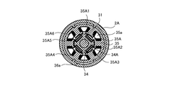
図4に示すように、ロータ34は回転軸31に同軸的に固定されており、4つの永久磁石34Aが設けられている。ステータ35は、モータハウジング2Aの内周面に設けられた複数のリブに支持されるとともに、コイル35Aを有する。コイル35Aは6つのコイル35A1〜35A6から成り、6つのコイル35A1〜35A6はステータ35に対して、コイル35A1の対極にコイル35A4が位置するように、コイル35A2の対極にコイル35A5が位置するように、コイル35A3の対極にコイル35A6が位置するように配置される。それぞれのコイル35Aの間には空隙35aが形成されている。ステータ36の外周面とモータハウジング2Aとの間にも隙間36aが形成されている。この空隙35a及び隙間36aを冷却ファン32による冷却風が流れることにより、ブラシレスモータ3が冷却される。
As shown in FIG. 4, the
図1に示すように、ギヤケース2Bはアルミ製(金属製)であって、内部に、回転駆動伝達機構4と、ボルトチップ排出機構5等が内蔵されている。回転駆動伝達機構4は前後方向に延び、ギヤ機構7と、遊星ギヤ機構8とにより構成される。ギヤケース2B内の後部には、ロッドカバー21が配置されている。ロッドカバー21には、後述のロッド51の後端部が挿入される挿入孔21aが前後方向に貫通して形成される。挿入孔21aは、その内径が後述のロッド51の外径より僅かに大きくなるように形成されている。ギヤケース2Bとモータハウジング2Aとは、図示せぬネジ(ビス)で互いに固定されている。
As shown in FIG. 1, the
ギヤ機構7は、遊星ギヤ機構8とブラシレスモータ3との間に介在しており、ピニオンギヤ31Aと噛合する第一ギヤ71と、第一ギヤ71に噛合する第二ギヤ部72と、第二ギヤ部72と噛合する第三ギヤ部73とから主に構成されている。第一ギヤ71は平ギヤであり、回転軸31の回転軸と平行な回転軸を有し、ハウジング2に回転可能に支持されている。第二ギヤ部72は、平ギヤであり第一ギヤ71と噛合する第二ギヤ72Aと第二ギヤ72Aと同軸一体回転する第一傘歯ギヤ72Bとを有している。第二ギヤ部72の回転軸は、第一ギヤ71と平行で、ハウジング2にベアリングを介して回転可能に支承されている。また第二ギヤ部72には、内部に後述のプレートロッド55が挿通される孔が上下方向に貫通している。第三ギヤ部73は、傘歯ギヤであり第一傘歯ギヤ72Bと噛合する第二傘歯ギヤ73Aと、第二傘歯ギヤ73Aの前側に位置し第二傘歯ギヤ73Aと同軸一体回転する第一太陽ギヤ73Bとを有している。第3ギヤ部73は、ベアリングを介してロッドカバー21に回転可能に支承されている。第三ギヤ部73は、その回転軸中心位置に前後方向に貫通する貫通孔が形成され、後述のロッド51が挿入されている。
The
遊星ギヤ機構8は、第一遊星ギヤ81、第二遊星ギヤ82、第三遊星ギヤ83、及びこれら第一〜第三遊星ギヤ81〜83のリングギヤとなる外周部8Aとから構成されている。第一遊星ギヤ81は、第三ギヤ部73の前方に配置され、第一太陽ギヤ73Bを太陽ギヤとし外周部8Aをリングギヤとして公転しており、第一太陽ギヤ73Bの回転を減速して出力する第二太陽ギヤ81Aを有している。第二遊星ギヤ82は、第一遊星ギヤ81の前方に配置され、第二太陽ギヤ81Aを太陽ギヤとし外周部8Aをリングギヤとして公転しており、第二太陽ギヤ81Aの回転を減速して出力する第三太陽ギヤ82Aを有している。第三遊星ギヤ83は、第二遊星ギヤ82の前方に配置され、第三太陽ギヤ82Aを太陽ギヤとし外周部8Aをリングギヤとして公転しており、第三太陽ギヤ82Aの回転を減速して出力する出力部83Aを有している。
The
出力部83Aは前端が開口しており、内部に後述のインナーソケット61を収容可能であって後述するウエイト52が収容されているソケット収容空間83aを有している。ソケット収容空間83aの内周には、前後方向に延びる複数の凹部から構成されるスプライン受部83Bが設けられている。また内周において、前端部分には後述の押さえボール61Cを受入れ可能なボール受部83bが形成されている。第一〜第三遊星ギヤ81〜83には、それぞれ前後方向に貫通する貫通孔が形成されており、第三遊星ギヤ83の貫通孔はソケット収容空間83a内に開口し、第一遊星ギヤ81の貫通孔の後端は第一太陽ギヤ73B前端側に開口し、第三ギヤ部73の貫通孔に連通している。
The
外周部8Aは、第一〜第三遊星ギヤ81〜83とのそれぞれと噛合するギヤを有し、第三遊星ギヤ83にベアリングを介して支持されている。故に外周部8Aは、ハウジング2に対して回転可能であると共に前後動不能である。
The outer
ボルトチップ排出機構5は、ロッド51と、ウエイト52と、ウエイト52を前方に付勢するウエイト付勢バネ53と、バネ54と、プレートロッド55と、プレート56とから主に構成されている。ロッド51は、外径が挿入孔21aより略小径の棒状に構成されており、先端がウエイト52に固定される。ロッド51の後端側には凹部51aが形成され、凹部51aを含む後端がソケット収容空間83a内から第一〜第三遊星ギヤ81〜83に形成された貫通孔、及び第三ギヤ部73に形成された貫通孔を貫通して、挿入孔21a内に配置されている。ウエイト52は、ウエイト付勢バネ53を受ける座部52Aと、座部52Aの前端に位置する付勢部52Bとから構成されており、ソケット収容空間83a内に配置されている。ウエイト付勢バネ53は、ソケット収容空間83a内に配置され、前端が座部52Aに着座すると共に後端がソケット収容空間83aの後端面に着座してウエイト52を前側へと付勢している。
The bolt
ギヤケース2Bの後方に位置するバネ54は、ロッドカバー21に支持されている。プレートロッド55は棒状に構成されており、第二ギヤ部72に形成された孔内に長手方向を上下方向として配置されており、上端が後述のプレート56の一端と当接可能であり、下端が後述のレバー23と当接可能な位置に配置されている。
The
プレート56は、バネ54とプレートロッド55との間に設けられていて、バネ54によって下側に付勢されている。プレート56には挿入孔21aより僅かに大きい貫通孔56aが形成されており、ロッド51が挿通可能となっている。
The
ソケット部6は主にインナーソケット61とソケット付勢バネ62とアウターソケット63とから構成されている。インナーソケット61は、スプライン部61Aと、チップ付勢部61Bと、押さえボール61Cとを有し、ソケット収容空間83a内に収容可能に構成されている。インナーソケット61の前方にはチップ保持空間61aが形成されている。インナーソケット61の外周面における前後方向の略中心位置に、後述のインナーソケット規制部材63Aと当接する段部が設けられている。
The
図5に示すように、チップ保持空間61aはインナーソケット61前端に開口して高張力ボルト11のボルトチップ11A(bolt tip)を収容・保持する構成を採っており、内周面にボルトチップ11Aのスプライン形状と嵌合するスプライン溝が形成されている。故にインナーソケット61とボルトチップ11Aとは共回りすることが可能になる。インナーソケット61においてチップ保持空間61aの底面となる部分には、ウエイト52の付勢部52Bが貫通してチップ保持空間61a内に突出可能な開孔61bが形成されている。またインナーソケット61において開孔61bの後方には、ウエイト52の座部52Aを収容可能な座部収容空間61cが形成されている。
As shown in FIG. 5, the
スプライン部61Aは、インナーソケット61外周の後端側に設けられており、ソケット収容空間83a内のスプライン受部83Bと係合している。これにより、インナーソケット61は出力部83Aに対して前後動可能かつ回転不能となり、インナーソケット61は出力部83Aと一体回転する。
The
チップ付勢部61Bは、チップ保持空間61a内周面に開口する孔内に配置されたボールと該ボールを付勢するバネとから構成されている。このボールがバネにより付勢されてチップ保持空間61a内に突出することによりチップ保持空間61a内に収容されたボルトチップ11Aと当接してボルトチップ11Aを保持することができる。
The
押さえボール61Cは、インナーソケット61の外周面と座部収容空間61c内周面とを貫通する孔内に上下方向に移動可能に配置されている。座部52Aが座部収容空間61c内に収容された状態で、押さえボール61Cが座部52A外周と当接してインナーソケット61外周面から突出する構成を採っている。よって、インナーソケット61が出力部83Aの前方に位置した状態で座部52Aが座部収容空間61c内に位置することにより、押さえボール61Cの一部がインナーソケット61外周面より突出してボール受部83bに挿入される(図1に示す状態)。この状態でインナーソケット61をソケット収容空間83a内に挿入しようとしても、ボール受部83bに受入れられた押さえボール61Cの一部がスプライン受部83Bに引っ掛かるため、インナーソケット61の後方への移動が規制される。座部52Aを座部収容空間61cから退出させることにより、押さえボール61Cが座部収容空間61c内に突出可能になると共にボール受部83bから退出可能になり、インナーソケット61の後方への移動が可能になる(図6に示す状態)。
The
ソケット付勢バネ62は、内部にウエイト52及びウエイト付勢バネ53を収容した状態でソケット収容空間83aに収容される。ソケット付勢バネ62は、前端がインナーソケット61に当接し、後端がソケット収容空間83aの後端面に当接するように構成されている。ソケット付勢バネ62によりインナーソケット61は前方へと付勢される。
The
アウターソケット63は、外周部8Aの前端部分に装着されて外周部8Aと一体回転し、ナット保持空間63aが形成され、インナーソケット規制部材63Aを備えている。ナット保持空間63aは、アウターソケット63前端に開口して内部にナット12と係合可能である。故にアウターソケット63とナット12とは共回りすることができる。インナーソケット規制部材63Aはナット保持空間63aの後端面位置に規定されており、インナーソケット61の前端部分のみが挿通可能な開孔63bを有している。インナーソケット61の前端部分が開孔63bを貫通した状態では、インナーソケット61の段部がインナーソケット規制部材63Aに当接するため、インナーソケット規制部材63Aによってインナーソケット61がソケット付勢バネ62の付勢力によりナット保持空間63a内に脱落することを防止している。
The
ハンドルハウジング2Cは断面形状略L字状であって、上部で図示せぬネジ(ビス)によってギヤケース2Bに固定されており、下部でネジ(ビス)22によってモータハウジング2Aの下端部に固定されている(図2)。ハンドルハウジング2Cには、図2、3に示すように、吸気口2cが、左右方向それぞれに上下方向に2箇所、前後方向に2箇所の合計8箇所形成されている。冷却ファン32が回転することによって吸気口2cから外気が吸入され、通気口2b、空隙35a(図4)、隙間36a(図4)を通って基板部9、基板33、ブラシレスモータ3をそれぞれ冷却して排気口2aより排出される(図2の矢印)。ハンドルハウジング2C内には、基板部9が収容される基板部収容空間9aが形成されており、基板部収容空間9a内にブラシレスモータ3を制御する基板部9が配置される。
The handle housing 2C has a substantially L-shaped cross section, and is fixed to the
ハンドルハウジング2Cとギヤケース2Bとの接続部分にはレバー23が配置され、その一部がハンドルハウジング2Cの外部に突出している。レバー23は、ボルトチップ排出機構5を操作するために設けられており、作業者に引かれることにより上方へと回動して、プレートロッド55をバネ54の付勢力に抗して上方に移動させる。具体的には、図1に示す状態(レバー23が回動していない状態)では、貫通孔56aの中心と挿入孔21aの中心はずれていて、プレート56の一部が挿入孔21aの一部を塞いでいる。この状態でレバー23が引かれて上方に回動することにより、プレートロッド55がレバー23に押されて上方へ移動し、プレート56はバネ54に抗って上方へと移動する。プレート56が上方へと移動することにより貫通孔56aの中心と挿入孔21aの中心とが一致する。
A
ハンドルハウジング2Cにはブラシレスモータ3への電源の供給を切替えるトリガ24が設けられており、トリガ24はスイッチ機構24Aと接続している。下部からは、図示せぬ外部電源に接続される電源コード25が延出している。
The handle housing 2C is provided with a
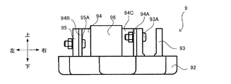
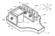
図7から13に示すように、基板部9は、回路基板91と(図1)、回路基板支持部92と、スイッチング素子93と、放熱部材94と、ダイオードブリッジ95と、コンデンサ96とを備えている。回路基板91は、前後方向に延びるように配置され、槽状の回路基板支持部92に収容されている。回路基板91は、電源ケーブル91Aを介して電源コード25と電気的に接続されており、電源ケーブル91Bを介してスイッチ機構24Aと電気的に接続されている。回路基板91上には、ブラシレスモータ3の駆動を制御する図示せぬマイクロコンピュータが搭載されている。回路基板支持部92は、左右方向に直交する断面がU字状をなし、回路基板91を収容できる程度の深さを有する。回路基板支持部92には、ウレタン樹脂92Aが充填されており、このウレタン樹脂92Aよって回路基板91を回路基板支持部92に固定するとともに、回路基板91の防振性を高め、回路基板91上の素子の絶縁を確保している。回路基板支持部92は、図示せぬリブによってハンドルハウジング2Cに支持されている。本実施の形態では、スイッチング素子93として、FET(FIELD EFFECT TRANSISTOR)を用いている。また、ダイオードブリッジ95はブリッジダイオードとも呼ばれ、公知のダイオードを4つ組み合わせたものであり、交流の商用電源を直流に整流するためのものである。
As shown in FIGS. 7 to 13, the
スイッチング素子93は、ステータ35への給電を行うことによってブラシレスモータ3の回転を制御するための素子であり、回路基板91の右側の吸気口2cの近傍に6つ配置される(図3)。より詳細には、図9に示すように、スイッチング素子93A1〜93A3は前後方向に並ぶように配置され(以下、列Aという)、列Aの左側に所定距離を空けてスイッチング素子93A4〜93A6が前後方向に並ぶように配置される(以下、列Bという)。列Aのスイッチング素子93A1〜93A3が、それぞれコイル35A1〜35A3と接続され、列Bのスイッチング素子93A4〜93A6が、それぞれコイル35A4〜35A6と接続されている。スイッチング素子93A1とスイッチング素子93A4とは、同時にコイル35A1とコイル35A4とに通電し、スイッチング素子93A2とスイッチング素子93A5とは、同時にコイル35A2とコイル35A5とに通電し、スイッチング素子93A3とスイッチング素子93A6とは、同時にコイル35A3とコイル35A6とに通電する。スイッチング素子93は上下方向と直交する断面が長方形をなし、長辺が前後方向に延びるように、短辺が左右方向に延びるように配置される。これにより、図3に示すように、吸気口2cに対向するように長辺側の側面が配置されることとなり、スイッチング素子93の冷却効率をより高めることができる。
The switching
スイッチング素子93の表層は導電性のある金属で覆われている。図7及び8に示すように、スイッチング素子93の上部には、左右方向に貫通する孔93aが形成されている。列Bに位置するスイッチング素子93の左側側面は、孔93aを通るボルト93Aによって放熱部材94と接続されている(図9)。スイッチング素子93と放熱部材94との接触面には、両者の密着性を高めてスイッチング素子93の熱が放熱部材94に伝わり易くするために、放熱グリスが塗布されている。列Bのスイッチング素子93が放熱部材94と接続されていることにより、列Aのスイッチング素子93が障壁となって吸気口2cからの冷却風が当たりにくい場合であっても、列Bのスイッチング素子93は十分な冷却効果を得ることができる。さらに、列Aの近傍に列Bを配置することによりスイッチング素子93が回路基板91上の1箇所に集まるため、効率的な回路配置が可能となり回路基板91を小型化することができる。
The surface layer of the switching
放熱部材94は、アルミ製であって上下方向に直交する断面が略コ字状をなし、スイッチング素子93と接続するスイッチング素子接続部94Aと、ダイオードブリッジ95と接続するダイオードブリッジ接続部94Bと、スイッチング素子接続部94Aとダイオードブリッジ接続部94Bとを繋ぐ横架部94Cとを有する。図10及び11に示すように、放熱部材94の上面はスイッチング素子93の上面と面一であって、図1及び8に示すように、スイッチング素子93の下面は回路基板91(ウレタン樹脂92A)と離間している。これにより、図2に示すようなスイッチング素子93の上方の空間(図示せぬ配線等が配置される)を確保するとともに、放熱部材94の熱が回路基板91に伝達することを防止している。
The
ダイオードブリッジ95は、交流を直流に変換するための整流回路であって、回路基板91上の左側の吸気口2cの近傍に配置される(図3)。ダイオードブリッジ95は上下方向に直交する断面が長方形をなし、長辺が前後方向に延びるように、短辺が左右方向に延びるように配置される。これにより、図3に示すように、吸気口2cに対向するように長辺側の側面が配置されることとなり、ダイオードブリッジ95の冷却効率を高めることができる。ダイオードブリッジ95の右側側面は、ボルト95Aによって放熱部材94のダイオードブリッジ接続部94Bと接続されている(図9)。これにより、ダイオードブリッジ95の発熱を効果的に放熱することができる。
The
コンデンサ96は、電源コード25からの電力を平滑化するために設けられており、回路基板91のスイッチング素子93とダイオオードブリッジ95との間に配置される。
The
次にシャーレンチ1の高張力ボルト11締め付け動作について説明する。高張力ボルト11及びナット12(図5)をチップ保持空間61a及びナット保持空間63aに挿入していない状態においては、図1に示されるように、インナーソケット61がソケット付勢バネ62により前方へと付勢されてインナーソケット61の前端部分がナット保持空間63a内に突出している。またウエイト52及びロッド51がウエイト付勢バネ53により前方へと付勢されて座部52Aが座部収容空間61c内に収容されると共に付勢部52Bがチップ保持空間61a内に突出している。
Next, the operation of tightening the
図5に示されるように、被加工部材たる鋼板Sに高張力ボルト11及びナット12を仮止めした状態で、ボルトチップ11Aをチップ保持空間61a内に挿入すると共にナット12をナット保持空間63a内に挿入する。ボルトチップ11Aをチップ保持空間61aに収容することにより、ボルトチップ11Aが付勢部52Bに当接し、ウエイト付勢バネ53の付勢力に抗してロッド51及びウエイト52を後方へ移動させる。これによって、座部52Aが座部収容空間61c内から退出するため、インナーソケット61がアウターソケット63に対して後方へと移動可能になる。この状態で、ナット12がナット保持空間63a内に挿入されることにより、ナット12がインナーソケット61に当接し、ソケット付勢バネ62の付勢力に抗してインナーソケット61及びウエイト52、ロッド51が後方へと移動する。この移動に伴ってロッド51の後端部分に位置する凹部51aがプレート56の貫通孔56aに引っ掛かり、ウエイト52、ロッド51の前方への移動が規制される。
As shown in FIG. 5, the
この状態でトリガ24を引くことによりブラシレスモータ3が駆動して冷却ファン32も回転する。これにより、吸気口2cから吸入された冷却風は基板部9、基板33、及びブラシレスモータ3を冷却し、排気口2aから外部に排出される。
By pulling the
同時に、ブラシレスモータ3の駆動力が回転駆動伝達機構4を介してソケット部6に伝達し、アウターソケット63に対しインナーソケット61を相対回転させる。そして、高張力ボルト11に対してナット12を締め付け、更にブラシレスモータ3を駆動して図6に示されるように、ボルトチップ11Aを高張力ボルト11からネジ切るように剪断する。この剪断により、高張力ボルト11に対してナット12を所定のトルクで締め付けることが可能になる。
At the same time, the driving force of the
高張力ボルト11にナット12を締め付けた後に、シャーレンチ1を高張力ボルト11から外すと、インナーソケット61はソケット付勢バネ62により前方へと付勢されるが、ウエイト52はロッド51の凹部51aが貫通孔56aに引っ掛かることで前方への移動が規制されているため、ナット12を締め付けた状態の位置と同じ位置に止まる。よって図6に示されるように、インナーソケット61からウエイト52までの間に隙間が発生する。またチップ保持空間61aに収容されているボルトチップ11Aは、チップ付勢部61Bにより付勢されているため、チップ保持空間61aから脱落することが抑制されている。
When the
この状態でレバー23を引き、バネ54の付勢力に抗ってプレート56を上方へと移動させることにより、貫通孔56aと凹部51aとの引っ掛かりが解かれる。ウエイト付勢バネ53の付勢力によりウエイト52が瞬間的に前進して付勢部52Bがチップ保持空間61a内のボルトチップ11Aに接触し、ボルトチップ11Aをチップ保持空間61a内から叩き出し、次の締め付けに備えることができる。
In this state, the
このような構成によると、放熱部材94がスイッチング素子93及びダイオードブリッジ95に接続されているため、回路基板91上の限られたスペースを有効的に利用してスイッチング素子93及びダイオードブリッジ95を効率的に冷却することができる。これにより、スイッチング素子93及びダイオードブリッジ95の熱による破損を防止できる。
According to such a configuration, since the
さらに、放熱部材94は吸気口2cと排気口2aとの間に配置されているため、冷却ファン32により発生した吸気口2cと排気口2aとの間を通る冷却風によって放熱部材94を効率的に冷却することができる。
Further, since the
さらに、横架部94Cが設けられていることによって放熱部材94の表面積が増加するため、スイッチング素子93及びダイオードブリッジ95を効率的に冷却することができる。
Furthermore, since the surface area of the
さらに、スイッチング素子93A1〜93A6は、対極に位置するコイル35A同士が同時に通電されるようにコイル35A1〜35A6の通電を制御している。そうすると、スイッチング素子93A1とスイッチング素子93A1の対極に位置するスイッチング素子93A4とが電気的に接続されている場合は、スイッチング素子同士のショートが起こる可能性がある。しかし、放熱部材94は、スイッチング素子93A4〜93A6にのみ接続されているため、スイッチング素子同士のショートが起きない。このため、一つの放熱部材94でスイッチング素子93A4〜93A6を放熱することができる。
Furthermore, the switching elements 93A1 to 93A6 control the energization of the coils 35A1 to 35A6 so that the
次に、第2の実施形態の電動工具の一例たるシャーレンチ201について図14から20に基づき説明する。第1の実施形態と同一の構成によるものは、同一の符号を付して説明を省略する。 Next, a shear wrench 201 as an example of the electric tool of the second embodiment will be described with reference to FIGS. Components having the same configuration as those of the first embodiment are denoted by the same reference numerals and description thereof is omitted.
図14から20に示すように、放熱部材294は、アルミ製であって上下方向に直交する断面が略コ字状をなし、スイッチング素子93と接続するスイッチング素子接続部294Aと、ダイオードブリッジ95と接続するダイオードブリッジ接続部294Bと、スイッチング素子接続部294Aとダイオードブリッジ接続部294Bとを繋ぐ横架部294Cとを有する。図16に示すように、スイッチング素子接続部294Aはボルト93Aによって列Bのスイッチング素子93の右側側面と接続されていて、ダイオードブリッジ接続部294Bはボルト95Aによってダイオードブリッジ95の右側側面と接続されている。第1の実施形態と同様に、スイッチング素子93とスイッチング素子接続部294Aとの接触面には、放熱グリスが塗布されている。このように、スイッチング素子接続部294Aが列Bのスイッチング素子93の右側側面と接続していることにより、スイッチング素子接続部294Aが吸気口2cの近傍に位置することとなり、吸気口2cからの冷却風を効率よく受けることができるためスイッチング素子93の発熱を効果的に放熱することができる。これにより、スイッチング素子93及びダイオードブリッジ95の熱による破損を防止できる。さらに、横架部294Cが設けられていることによって放熱部材294の表面積が増加するため、スイッチング素子93及びダイオードブリッジ95の発熱を効果的に放熱することができる。
14 to 20, the
次に、第3の実施形態の電動工具の一例たるシャーレンチ301について図21から27に基づき説明する。第1の実施形態と同一の構成によるものは、同一の符号を付して説明を省略する。 Next, a shear wrench 301 as an example of the electric tool of the third embodiment will be described with reference to FIGS. Components having the same configuration as those of the first embodiment are denoted by the same reference numerals and description thereof is omitted.
図21から27に示すように、放熱部材394は、アルミ製であって、スイッチング素子93と接続するスイッチング素子接続部394Aと、ダイオードブリッジ95と接続するダイオードブリッジ接続部394Bと、スイッチング素子接続部394Aとダイオードブリッジ接続部394Bとを繋ぐ横架部394Cと、コンデンサ96と接続するコンデンサ接続部394Dとを有する。図23に示すように、スイッチング素子接続部394Aは、ボルト93Aによって列Bのスイッチング素子93の左側側面と接続されていて、ダイオードブリッジ接続部394Bはボルト95Aによってダイオードブリッジ95の右側側面と接続されている。図22に示すように、コンデンサ接続部394Dは、ダイオードブリッジ接続部394Bの上端から延出され屈曲してコンデンサ96の上面と接続するように設けられている。このように、コンデンサ接続部394Dとコンデンサ96とが接続していることにより、コンデンサ96の発熱を効果的に放熱することができる。これにより、コンデンサ96の熱による破損を防止できる。また、コンデンサ接続部393Dがコンデンサ96の上面を覆っていることにより、ハウジング2の内部の変形によりハウジング2の一部とコンデンサ96とが接触してしまうことを防ぐことができる。
As shown in FIGS. 21 to 27, the
次に、第4の実施形態の電動工具の一例たるシャーレンチ401について図28から34に基づき説明する。第1の実施形態と同一の構成によるものは、同一の符号を付して説明を省略する。 Next, a shear wrench 401 as an example of the electric tool of the fourth embodiment will be described with reference to FIGS. Components having the same configuration as those of the first embodiment are denoted by the same reference numerals and description thereof is omitted.
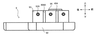
図28から34に示すように、放熱部材494は、スイッチング素子93と接続するスイッチング素子接続部494Aと、ダイオードブリッジ95と接続するダイオードブリッジ接続部494Bとを有する。図28に示すように、スイッチング素子接続部494Aとダイオードブリッジ接続部494Bとは互いに分断されている。図30に示すように、スイッチング素子接続部494Aはボルト93Aによって列Bのスイッチング素子93の左側側面と接続されていて、ダイオードブリッジ接続部494Bはボルト95Aによってダイオードブリッジ95の右側側面と接続されている。このように、スイッチング素子接続部494Aとダイオードブリッジ接続部494Bとが分断されていることにより回路基板91上の空間が広くなるため、回路基板91上に素子を配置する際の作業性が向上する。
As shown in FIGS. 28 to 34, the
次に、第5の実施形態の電動工具の一例たるシャーレンチ501について図35から41に基づき説明する。第1の実施形態と同一の構成によるものは、同一の符号を付して説明を省略する。 Next, a shear wrench 501 as an example of the electric tool of the fifth embodiment will be described with reference to FIGS. Components having the same configuration as those of the first embodiment are denoted by the same reference numerals and description thereof is omitted.
図37に示すように、回路基板91上には6つのスイッチング素子593と、放熱部材594とが設けられている。スイッチング素子593A1〜593A3は前後方向に並ぶように配置され(以下、列Aという)、列Aの左側に所定距離を空けてスイッチング素子593A4〜593A6が前後方向並ぶように配置される(以下、列Bという)。第5の実施形態での所定距離は、第1〜4の実施形態の所定距離よりも小さく設定されている。具体的には、所定距離は放熱部材594の厚みと略同一に設定されている。
As shown in FIG. 37, six switching
図35から41に示すように、放熱部材594は、アルミ製であって上下方向に直交する断面が略コ字状をなし、スイッチング素子593と接続するスイッチング素子接続部594Aと、ダイオードブリッジ95と接続するダイオードブリッジ接続部594Bと、スイッチング素子接続部594Aとダイオードブリッジ接続部594Bとを繋ぐ横架部594Cとを有する。図37に示すように、スイッチング素子接続部594Aは、ボルト593Aによって列Aのスイッチング素子593の左側側面及び列Bのスイッチング素子593の右側側面と接続されている。スイッチング素子593とスイッチング素子接続部594Aとの接触面には、両者の密着性を高めるとともに列Aのスイッチング素子593と列Bのスイッチング素子593との電気絶縁性を確保するための絶縁性を有するゴムにより構成されるシート状部材が設けられている。ダイオードブリッジ接続部594Bは、ボルト95Aによってダイオードブリッジ95の右側側面と接続されている。これにより、列Aのスイッチング素子593も放熱部材594と接続しているため、列Aのスイッチング素子593の発熱を効果的に放熱することができる。これにより、スイッチング素子93及びダイオードブリッジ95が熱によって破損することを防止できる。
35 to 41, the
本発明によるシャーレンチは上述した実施の形態に限定されず、特許請求の範囲に記載された発明の要旨の範囲内で種々の変更が可能である。 The shear wrench according to the present invention is not limited to the embodiment described above, and various modifications are possible within the scope of the gist of the invention described in the claims.
本実施形態では、放熱部材としてアルミを用いたが、銅やステンレスなどの他の金属材料を用いてもよい。 In this embodiment, aluminum is used as the heat dissipation member, but other metal materials such as copper and stainless steel may be used.
本実施形態では、放熱部材とスイッチング素子との接触面に放熱グリスが塗布されていたが、放熱グリスを塗布せずに直接両者を接触させても良い。 In the present embodiment, the heat dissipation grease is applied to the contact surface between the heat dissipation member and the switching element, but both may be directly brought into contact without applying the heat dissipation grease.
本実施形態では、放熱部材は表面が平滑なものを用いたが、放熱部材の表面に凹凸をつけてもよい。これによって、放熱部材の表面積が増加してより高い冷却効率を得ることができる。 In the present embodiment, the heat radiating member has a smooth surface, but the surface of the heat radiating member may be uneven. Thereby, the surface area of the heat radiating member is increased, and higher cooling efficiency can be obtained.
本実施形態では、ダイオードブリッジの右側側面に放熱部材を接続したが、ダイオードブリッジの左側側面に放熱部材を接続してもよい。これにより、放熱部材が吸気口の近傍に位置することとなるため、より高い冷却効率をえることができる。」 In the present embodiment, the heat dissipation member is connected to the right side surface of the diode bridge, but the heat dissipation member may be connected to the left side surface of the diode bridge. Thereby, since a heat radiating member will be located in the vicinity of an inlet port, higher cooling efficiency can be obtained. "
本実施形態では、スイッチング素子としてFETを6つ用いたが、FETの数は2つでも良い。また、4つでも、8つでも良い。 In the present embodiment, six FETs are used as switching elements, but the number of FETs may be two. Moreover, four or eight may be sufficient.
本実施形態では、ダイオードブリッジとして公知のダイオードが4つ組み合わせたものを用いたが、ダイオードブリッジ以外の整流素子を用いてもよい。例えば、ダイオードを一つのみ用いても良い。 In the present embodiment, a combination of four known diodes is used as the diode bridge, but a rectifying element other than the diode bridge may be used. For example, only one diode may be used.
本実施形態では、放熱部材はスイッチング素子に固定されていたが、基板に対してネジで固定するものであっても良い。 In this embodiment, the heat dissipation member is fixed to the switching element, but may be fixed to the substrate with screws.
また、本発明は電動工具の一例としてシャーレンチを用いたが、シャーレンチ以外の電動工具、例えばハンマやハンマドリルに適用してもよい。 Moreover, although the shear wrench was used as an example of the electric tool in the present invention, it may be applied to an electric tool other than the shear wrench, for example, a hammer or a hammer drill.
また、ブラシレスモータへの給電は、電源コードによって行う構造としたが、繰返し充電可能な充電池(バッテリ)によって給電する構成としてもよい。 In addition, the power supply to the brushless motor is performed by the power cord, but the power supply may be performed by a rechargeable battery (battery) that can be repeatedly charged.
1・・シャーレンチ 2・・ハウジング 2A・・モータハウジング 2B・・ギヤケース 2C・・ハンドルハウジング 3・・ブラシレスモータ 4・・回転駆動伝達機構 5・・ボルトチップ排出機構 6・・ソケット部 7・・ギヤ機構 8・・遊星ギヤ機構 9・・基板部 32・・冷却ファン 34・・ロータ 35・・ステータ 35A・・コイル 91・・回路基板 93・・スイッチング素子 94・・放熱部材 95・・ダイオードブリッジ 96・・コンデンサ
1 ..
Claims (15)
前記ハウジングに収容され、上下に延びる回転軸を有するブラシレスモータと、
前記ブラシレスモータの上方で前記回転軸に固定される冷却ファンと、
前記ブラシレスモータを制御する制御部と、前記ブラシレスモータを駆動するためのスイッチング素子と、を有し、前記回転軸の軸線上で前記ブラシレスモータの下方に配置される基板部と、
前後方向に延び、前記回転軸の回転が伝達される出力部と、を備え、
前記ハウジングは、排気口が設けられ前記ブラシレスモータを収容するモータ収容部と、吸気口が設けられ前記基板部を収容する基板部収容部と、を有し、
前記モータ収容部と前記基板部収容部との間を区画する隔壁に前記モータ収容部と前記基板部収容部とを繋ぐ通気口を前記基板部の上方に設け、前記冷却ファンの回転によって前記吸気口から前記基板部収容部に流入した冷却風は前記基板部を冷却した後に前記通気口を介して前記モータ収容部に流入して前記ブラシレスモータの内部を通り、その後前記排気口から排出されることを特徴とする電動工具。 A housing;
A brushless motor housed in the housing and having a rotating shaft extending vertically ;
A cooling fan fixed to the rotating shaft above the brushless motor ;
A control unit for controlling the brushless motor, said to have a, a switching element for driving a brushless motor, a substrate portion which is arranged below the brushless motor on the axis of the rotary shaft,
An output part extending in the front-rear direction and transmitting the rotation of the rotary shaft ,
The housing has a motor accommodating portion that is provided with an exhaust port and accommodates the brushless motor, and a substrate portion accommodating portion that is provided with an intake port and accommodates the substrate portion,
An air vent connecting the motor housing portion and the substrate portion housing portion is provided above the substrate portion in a partition wall that partitions the motor housing portion and the substrate portion housing portion, and the intake air is rotated by rotation of the cooling fan. Cooling air that has flowed into the substrate housing portion from the opening cools the substrate portion, then flows into the motor housing portion through the vent, passes through the brushless motor, and is then discharged from the exhaust port. An electric tool characterized by that.
前記回路基板支持部は前記基板部収容部に収容されていることを特徴とする請求項1に記載の電動工具。 The board part includes a circuit board on which the control part is mounted, a heat dissipation member connected to the switching element, and a circuit board support part that contains the circuit board and is filled with an insulating material,
The electric power tool according to claim 1 , wherein the circuit board support portion is accommodated in the substrate portion accommodation portion.
前記基板部は、前記制御部が搭載される回路基板を有し、
前記通気口には、前記コイルと前記回路基板とを接続するケーブルが通ることを特徴とする請求項1に記載の電動工具。 The brushless motor has a rotor fixed coaxially to the rotating shaft, and a stator having a coil,
The substrate unit has a circuit board on which the control unit is mounted,
The power tool according to claim 1, wherein a cable connecting the coil and the circuit board passes through the vent hole.
前後方向に延び、前記回転軸の回転が伝達される出力部と、
前記ブラシレスモータを駆動するスイッチング素子と、
前記ブラシレスモータを収容するモータハウジングと、前記モータハウジングの上方で前記回転軸に固定された冷却ファンを収容し排気口を有するファン収容部と、前記モータハウジングに連結されるハンドルハウジングと、を備えるハウジングと、を備えた電動工具であって、
前記ハウジングは、吸気口が設けられ、前記回転軸の軸線上で前記ブラシレスモータの下方に前記スイッチング素子を搭載した基板部を収容する基板部収容部を有し、
前記基板部収容部と前記モータハウジングとを区画する部分であって前記基板部の上方に、前記基板部収容部と前記モータハウジングとを連通する通気口を設け、
前記冷却ファンの回転によって前記吸気口から前記基板部収容部内に吸入された空気は、前記基板部を冷却した後に前記通気口を介して前記モータハウジングに導入されて前記ブラシレスモータを冷却し、その後、前記ファン収容部に導入されて前記排気口から排出されることを特徴とする電動工具。 A brushless motor having a rotating shaft extending vertically ;
An output part extending in the front-rear direction and transmitting the rotation of the rotary shaft;
A switching element for driving the brushless motor;
A motor housing that houses the brushless motor; a fan housing portion that houses a cooling fan fixed to the rotating shaft above the motor housing and has an exhaust port; and a handle housing connected to the motor housing. A power tool comprising a housing,
The housing is provided with an air inlet, and has a substrate portion accommodating portion that accommodates a substrate portion on which the switching element is mounted below the brushless motor on the axis of the rotation shaft ,
A portion that divides the substrate portion accommodating portion and the motor housing and provided above the substrate portion with a vent hole that communicates the substrate portion accommodating portion and the motor housing,
Air that has been sucked into the board housing part from the air inlet by the rotation of the cooling fan is introduced into the motor housing through the air vent after cooling the board to cool the brushless motor, and then The electric tool is introduced into the fan housing portion and discharged from the exhaust port .
前記冷却風路は、前記吸気口、前記基板部収容部、前記通気口、前記モータハウジング、前記ファン収容部、前記排気口から形成されることを特徴とする請求項9に記載の電動工具。 A cooling air passage through which air generated by the rotation of the cooling fan passes is formed in the housing,
The electric power tool according to claim 9 , wherein the cooling air passage is formed from the intake port, the board portion accommodating portion, the vent hole, the motor housing, the fan accommodating portion, and the exhaust port.
前記ブラシレスモータの上方側に配置されて前記回転軸に固定される冷却ファンと、
前記ブラシレスモータの上方側に配置されて前後方向に延びる出力部と、
前記ブラシレスモータの下方側に配置されて前後方向に延び、前記ブラシレスモータを駆動するスイッチング素子及び前記スイッチング素子に接続される放熱部材を有する基板部と、
前記ブラシレスモータを収容するモータ収容部と、前記冷却ファンを収容するファン収容部と、前記基板部を収容する基板部収容部と、を有するハウジングと、を備え、
前記回転軸の軸線上において、上から順に前記冷却ファン、前記ブラシレスモータ、前記基板部が前記ハウジング内に収容され、
前記ファン収容部には排気口が形成されると共に前記基板部収容部には吸気口が形成され、
前記吸気口から前記排気口までの冷却風路に、前記モータ収容部と前記基板部収容部とを上下に連通する通気口を設け、前記冷却ファンの回転によって前記吸気口から前記基板部収容部内に吸入された空気は、前記基板部を冷却した後に前記通気口を介して前記モータ収容部に導入されて前記ブラシレスモータを冷却し、その後、前記ファン収容部に導入されて前記排気口から排出されることを特徴とする電動工具。 A brushless motor having a rotating shaft extending in the vertical direction;
A cooling fan disposed on the upper side of the brushless motor and fixed to the rotating shaft;
An output unit disposed on the upper side of the brushless motor and extending in the front-rear direction;
A substrate portion that is disposed on the lower side of the brushless motor and extends in the front-rear direction, and includes a switching element that drives the brushless motor and a heat dissipation member connected to the switching element;
A housing having a motor accommodating portion for accommodating the brushless motor, a fan accommodating portion for accommodating the cooling fan, and a substrate portion accommodating portion for accommodating the substrate portion;
On the axis of the rotating shaft, the cooling fan, the brushless motor, and the substrate unit are accommodated in the housing in order from the top,
An exhaust port is formed in the fan housing portion and an intake port is formed in the substrate portion housing portion,
A cooling air passage from the intake port to the exhaust port is provided with a vent hole that vertically communicates the motor accommodating portion and the substrate portion accommodating portion, and the cooling fan rotates to bring the inside of the substrate portion accommodating portion from the intake port. The air sucked into the air is introduced into the motor housing portion through the vent after cooling the substrate portion to cool the brushless motor, and then introduced into the fan housing portion and discharged from the exhaust port. An electric tool characterized by being made .
Priority Applications (4)
| Application Number | Priority Date | Filing Date | Title |
|---|---|---|---|
| JP2010159551A JP5534562B2 (en) | 2010-07-14 | 2010-07-14 | Electric tool |
| US13/182,332 US8928261B2 (en) | 2010-07-14 | 2011-07-13 | Power tool having circuit board |
| CN201110196772.3A CN102335895B (en) | 2010-07-14 | 2011-07-14 | Power tool having circuit board |
| US14/505,146 US9882452B2 (en) | 2010-07-14 | 2014-10-02 | Power tool having circuit board |
Applications Claiming Priority (1)
| Application Number | Priority Date | Filing Date | Title |
|---|---|---|---|
| JP2010159551A JP5534562B2 (en) | 2010-07-14 | 2010-07-14 | Electric tool |
Related Child Applications (1)
| Application Number | Title | Priority Date | Filing Date |
|---|---|---|---|
| JP2014092464A Division JP5777024B2 (en) | 2014-04-28 | 2014-04-28 | Electric tool |
Publications (3)
| Publication Number | Publication Date |
|---|---|
| JP2012020363A JP2012020363A (en) | 2012-02-02 |
| JP2012020363A5 JP2012020363A5 (en) | 2013-10-31 |
| JP5534562B2 true JP5534562B2 (en) | 2014-07-02 |
Family
ID=45466830
Family Applications (1)
| Application Number | Title | Priority Date | Filing Date |
|---|---|---|---|
| JP2010159551A Active JP5534562B2 (en) | 2010-07-14 | 2010-07-14 | Electric tool |
Country Status (3)
| Country | Link |
|---|---|
| US (2) | US8928261B2 (en) |
| JP (1) | JP5534562B2 (en) |
| CN (1) | CN102335895B (en) |
Families Citing this family (34)
| Publication number | Priority date | Publication date | Assignee | Title |
|---|---|---|---|---|
| JP5534562B2 (en) * | 2010-07-14 | 2014-07-02 | 日立工機株式会社 | Electric tool |
| WO2014069369A1 (en) | 2012-10-29 | 2014-05-08 | 日立工機株式会社 | Electrical power tool |
| US9871424B2 (en) * | 2013-02-06 | 2018-01-16 | Hitachi Koki Co., Ltd. | Electric tool |
| DE102013202676A1 (en) * | 2013-02-19 | 2014-08-21 | Robert Bosch Gmbh | Hand tool |
| US9718180B2 (en) | 2013-05-09 | 2017-08-01 | Black & Decker Inc. | Power tool having improved motor and controller cooling |
| JP2015020257A (en) * | 2013-07-22 | 2015-02-02 | 株式会社マキタ | Electric power tool |
| JP6234128B2 (en) * | 2013-09-11 | 2017-11-22 | 株式会社マキタ | Electric tool |
| US9762153B2 (en) | 2013-10-18 | 2017-09-12 | Black & Decker Inc. | Cycle-by-cycle current limit for power tools having a brushless motor |
| US9314900B2 (en) * | 2013-10-18 | 2016-04-19 | Black & Decker Inc. | Handheld grinder with a brushless electric motor |
| WO2015079645A2 (en) * | 2013-11-26 | 2015-06-04 | Hitachi Koki Co., Ltd. | Electrical power tool |
| JP6398187B2 (en) * | 2013-12-20 | 2018-10-03 | 工機ホールディングス株式会社 | Electric tool |
| JP2015120208A (en) * | 2013-12-20 | 2015-07-02 | 日立工機株式会社 | Electric tool |
| CN105829031B (en) | 2013-12-20 | 2019-01-04 | 工机控股株式会社 | Electric tool |
| JP6328473B2 (en) | 2014-04-09 | 2018-05-23 | 株式会社マキタ | Electric tool |
| WO2016031719A1 (en) * | 2014-08-29 | 2016-03-03 | 日立工機株式会社 | Electric working machine |
| US10411958B2 (en) * | 2014-09-08 | 2019-09-10 | Intel Corporation | Automatic device configuration |
| JP2016087702A (en) * | 2014-10-29 | 2016-05-23 | 日立工機株式会社 | Electric power tool |
| JP6439382B2 (en) * | 2014-10-29 | 2018-12-19 | 工機ホールディングス株式会社 | Power working machine |
| US20170312902A1 (en) * | 2014-10-29 | 2017-11-02 | Hitachi Koki Co., Ltd. | Powered working machine |
| US11052530B2 (en) | 2014-10-31 | 2021-07-06 | Koki Holdings Co., Ltd. | Electric work machine |
| JP6460123B2 (en) * | 2014-12-18 | 2019-01-30 | 工機ホールディングス株式会社 | Electric tool |
| US10050572B2 (en) | 2014-12-19 | 2018-08-14 | Black & Decker Inc. | Power tool with electric motor and auxiliary switch path |
| JP6443541B2 (en) * | 2015-04-24 | 2018-12-26 | 工機ホールディングス株式会社 | Electric tool |
| WO2017154523A1 (en) * | 2016-03-05 | 2017-09-14 | 日立工機株式会社 | Electrically powered tool |
| JP6749169B2 (en) | 2016-07-29 | 2020-09-02 | 株式会社マキタ | Electric work machine |
| EP3318358B1 (en) * | 2016-11-07 | 2021-06-23 | Nanjing Chervon Industry Co., Ltd. | Power tool |
| US20180205292A1 (en) * | 2017-01-17 | 2018-07-19 | Headline Electric Co., Ltd. | Motor forcibly cooling device with rear drive assembly |
| JP7235046B2 (en) * | 2018-04-27 | 2023-03-08 | 工機ホールディングス株式会社 | Electric tool |
| US10525535B1 (en) * | 2018-09-05 | 2020-01-07 | Luraco, Inc. | Portable and rechargeable drill system |
| WO2020192214A1 (en) * | 2019-03-28 | 2020-10-01 | 南京德朔实业有限公司 | Electrical tool |
| DE102019207977A1 (en) * | 2019-05-29 | 2020-12-03 | Robert Bosch Gmbh | Cooling device for a hand machine tool |
| EP3831532B1 (en) | 2019-12-06 | 2023-07-26 | Black & Decker Inc. | A shear wrench tool |
| TWI750884B (en) * | 2020-11-04 | 2021-12-21 | 朝程工業股份有限公司 | electrical tools |
| SE2130369A1 (en) * | 2021-12-17 | 2023-06-18 | Atlas Copco Ind Technique Ab | Power tool and load-responsive power transmission for a power tool |
Family Cites Families (41)
| Publication number | Priority date | Publication date | Assignee | Title |
|---|---|---|---|---|
| JP2596444Y2 (en) | 1993-12-17 | 1999-06-14 | 日立工機株式会社 | Impact tool |
| DE19631517A1 (en) | 1996-08-03 | 1998-02-05 | Wacker Werke Kg | Variable-speed, hand-held power tool driven by an electric motor that can be connected to single-phase alternating current |
| JPH10156745A (en) * | 1996-11-28 | 1998-06-16 | Maeda Kinzoku Kogyo Kk | Motor-driven bolt fastener |
| JP3261398B2 (en) | 1997-10-29 | 2002-02-25 | 前田金属工業株式会社 | Bolt and nut tightening machine |
| JP3260677B2 (en) | 1997-11-28 | 2002-02-25 | 前田金属工業株式会社 | Bolt and nut tightening machine |
| US6102632A (en) * | 1998-04-23 | 2000-08-15 | Black & Decker Inc. | Two speed right angle drill |
| US6683396B2 (en) * | 1999-07-02 | 2004-01-27 | Matsushita Electric Works, Ltd. | Portable motor powered device |
| DE10021355B4 (en) | 2000-05-02 | 2005-04-28 | Hilti Ag | Beating electric hand tool with vibration-decoupled assemblies |
| JP3281360B2 (en) | 2000-07-28 | 2002-05-13 | 前田金属工業株式会社 | Bolt tightening machine with inspection function |
| DE10117121A1 (en) | 2001-04-06 | 2002-10-17 | Bosch Gmbh Robert | Hand tool |
| US6661140B2 (en) | 2001-12-11 | 2003-12-09 | Black & Decker Inc. | Brushless motor having housing enabling alignment of stator and sensor |
| JP2003199310A (en) | 2001-12-26 | 2003-07-11 | Nidec Shibaura Corp | Brushless dc motor and power tool |
| DE10242414A1 (en) | 2002-09-12 | 2004-03-25 | Hilti Ag | Power tool with blower |
| JP3918793B2 (en) | 2003-09-24 | 2007-05-23 | 日立工機株式会社 | Cordless fastening tool |
| JP4485190B2 (en) | 2003-12-26 | 2010-06-16 | 株式会社マキタ | Electric hammer |
| JP2006060140A (en) | 2004-08-23 | 2006-03-02 | Denso Corp | Electronic component control board and method for assembling same |
| JP2006141105A (en) | 2004-11-11 | 2006-06-01 | Hitachi Koki Co Ltd | Electric motor and power tool equipped therewith |
| JP4487836B2 (en) * | 2005-04-20 | 2010-06-23 | 日立工機株式会社 | Electric tool |
| JP4631663B2 (en) | 2005-11-17 | 2011-02-16 | パナソニック電工株式会社 | Electric tool |
| JP2008126344A (en) * | 2006-11-17 | 2008-06-05 | Hitachi Koki Co Ltd | Power tool |
| JP2008173716A (en) | 2007-01-18 | 2008-07-31 | Max Co Ltd | Electric power tool having brushless motor |
| JP4998846B2 (en) | 2007-01-18 | 2012-08-15 | 日立工機株式会社 | Cordless power tool |
| JP2008193865A (en) | 2007-02-07 | 2008-08-21 | Nidec Shibaura Corp | Motor driving device |
| JP4993193B2 (en) | 2007-05-30 | 2012-08-08 | 日立工機株式会社 | Electric tool |
| JP5013314B2 (en) | 2007-06-18 | 2012-08-29 | 日立工機株式会社 | Electric tool |
| JP5053791B2 (en) | 2007-10-15 | 2012-10-17 | 株式会社マキタ | Impact tool |
| GB2455122A (en) * | 2007-11-29 | 2009-06-03 | Technelec Ltd | Control of electrical machines |
| DE102008009233A1 (en) | 2008-02-04 | 2009-08-06 | REMS-WERK Christian Föll und Söhne GmbH & Co KG | Drive unit for tools, preferably for core drill bits |
| US20110248583A1 (en) * | 2008-02-07 | 2011-10-13 | Atlas Dynamic Devices, Llc | Power Transmission Tool And System |
| JP5248151B2 (en) | 2008-03-12 | 2013-07-31 | 株式会社マキタ | Electric tool |
| JP2009240023A (en) | 2008-03-26 | 2009-10-15 | Nidec Shibaura Corp | Motor controller, brushless motor, and power tool |
| US7791232B2 (en) * | 2008-05-02 | 2010-09-07 | Black & Decker Inc. | Power tool having an electronically commutated motor and double insulation |
| JP5217621B2 (en) | 2008-05-19 | 2013-06-19 | マックス株式会社 | Wiring structure in reinforcing bar binding machine |
| JP5370809B2 (en) * | 2008-09-01 | 2013-12-18 | 日立工機株式会社 | Electric tool |
| JP5477759B2 (en) | 2008-07-30 | 2014-04-23 | 日立工機株式会社 | Electric tool |
| JP4793425B2 (en) * | 2008-11-10 | 2011-10-12 | パナソニック電工株式会社 | Rechargeable power tool |
| JP4793426B2 (en) * | 2008-11-10 | 2011-10-12 | パナソニック電工株式会社 | Rechargeable power tool |
| JP5309920B2 (en) | 2008-11-19 | 2013-10-09 | 日立工機株式会社 | Electric tool |
| JP5472683B2 (en) * | 2009-05-11 | 2014-04-16 | 日立工機株式会社 | Electric tool |
| US20110273118A1 (en) * | 2010-05-10 | 2011-11-10 | David Bonner | Power Factor Correction Circuit |
| JP5534562B2 (en) * | 2010-07-14 | 2014-07-02 | 日立工機株式会社 | Electric tool |
-
2010
- 2010-07-14 JP JP2010159551A patent/JP5534562B2/en active Active
-
2011
- 2011-07-13 US US13/182,332 patent/US8928261B2/en active Active
- 2011-07-14 CN CN201110196772.3A patent/CN102335895B/en active Active
-
2014
- 2014-10-02 US US14/505,146 patent/US9882452B2/en active Active
Also Published As
| Publication number | Publication date |
|---|---|
| US8928261B2 (en) | 2015-01-06 |
| US20120014065A1 (en) | 2012-01-19 |
| US9882452B2 (en) | 2018-01-30 |
| CN102335895B (en) | 2015-05-27 |
| US20150015094A1 (en) | 2015-01-15 |
| CN102335895A (en) | 2012-02-01 |
| JP2012020363A (en) | 2012-02-02 |
Similar Documents
| Publication | Publication Date | Title |
|---|---|---|
| JP5534562B2 (en) | Electric tool | |
| JP5777024B2 (en) | Electric tool | |
| JP5582337B2 (en) | Electric tool | |
| US9590475B2 (en) | Electric power tool | |
| US9457459B2 (en) | Power tool provided with circuit board | |
| JP5333719B2 (en) | Electric tool | |
| WO2016067997A1 (en) | Powered working machine | |
| JP6911943B2 (en) | Electric tool | |
| JP5594642B2 (en) | Electric tool | |
| JP6169437B2 (en) | Electric tool | |
| JP6287110B2 (en) | Electric tool | |
| JP5725354B2 (en) | Electric tool | |
| JP5170677B2 (en) | Electric tool | |
| JP6626944B2 (en) | Electric tool | |
| JP6404399B2 (en) | Screw driver | |
| JP5574156B2 (en) | Bolt tightening machine | |
| JP6138526B2 (en) | Screw driver | |
| JP6615298B2 (en) | Power tools | |
| JP5170624B2 (en) | Flat cable protection structure | |
| JP5850279B2 (en) | Electric tool | |
| JP6724563B2 (en) | tool | |
| CN114670291A (en) | Chain saw | |
| JP2023020813A (en) | Electric tool and impact driver | |
| JP2007290071A (en) | Power tool device | |
| JP2022092644A (en) | Power tool |
Legal Events
| Date | Code | Title | Description |
|---|---|---|---|
| A521 | Request for written amendment filed |
Free format text: JAPANESE INTERMEDIATE CODE: A523 Effective date: 20130415 |
|
| A621 | Written request for application examination |
Free format text: JAPANESE INTERMEDIATE CODE: A621 Effective date: 20130415 |
|
| A521 | Request for written amendment filed |
Free format text: JAPANESE INTERMEDIATE CODE: A523 Effective date: 20130917 |
|
| A871 | Explanation of circumstances concerning accelerated examination |
Free format text: JAPANESE INTERMEDIATE CODE: A871 Effective date: 20130917 |
|
| A975 | Report on accelerated examination |
Free format text: JAPANESE INTERMEDIATE CODE: A971005 Effective date: 20131002 |
|
| A977 | Report on retrieval |
Free format text: JAPANESE INTERMEDIATE CODE: A971007 Effective date: 20140108 |
|
| A131 | Notification of reasons for refusal |
Free format text: JAPANESE INTERMEDIATE CODE: A131 Effective date: 20140116 |
|
| A521 | Request for written amendment filed |
Free format text: JAPANESE INTERMEDIATE CODE: A523 Effective date: 20140317 |
|
| TRDD | Decision of grant or rejection written | ||
| A01 | Written decision to grant a patent or to grant a registration (utility model) |
Free format text: JAPANESE INTERMEDIATE CODE: A01 Effective date: 20140407 |
|
| R150 | Certificate of patent or registration of utility model |
Ref document number: 5534562 Country of ref document: JP Free format text: JAPANESE INTERMEDIATE CODE: R150 |
|
| A61 | First payment of annual fees (during grant procedure) |
Free format text: JAPANESE INTERMEDIATE CODE: A61 Effective date: 20140420 |
|
| RVTR | Cancellation due to determination of trial for invalidation | ||
| R157 | Certificate of patent or utility model (correction) |
Free format text: JAPANESE INTERMEDIATE CODE: R157 |