JP6438418B2 - Surface mountable electrical circuit protection device - Google Patents
Surface mountable electrical circuit protection device Download PDFInfo
- Publication number
- JP6438418B2 JP6438418B2 JP2016009361A JP2016009361A JP6438418B2 JP 6438418 B2 JP6438418 B2 JP 6438418B2 JP 2016009361 A JP2016009361 A JP 2016009361A JP 2016009361 A JP2016009361 A JP 2016009361A JP 6438418 B2 JP6438418 B2 JP 6438418B2
- Authority
- JP
- Japan
- Prior art keywords
- electrode
- support substrate
- cavity
- electrical circuit
- voltage variable
- Prior art date
- Legal status (The legal status is an assumption and is not a legal conclusion. Google has not performed a legal analysis and makes no representation as to the accuracy of the status listed.)
- Active
Links
- 239000000758 substrate Substances 0.000 claims description 219
- 239000000463 material Substances 0.000 claims description 166
- 238000000034 method Methods 0.000 claims description 16
- 239000010949 copper Substances 0.000 claims description 15
- 239000004020 conductor Substances 0.000 claims description 14
- PXHVJJICTQNCMI-UHFFFAOYSA-N Nickel Chemical compound [Ni] PXHVJJICTQNCMI-UHFFFAOYSA-N 0.000 claims description 12
- BASFCYQUMIYNBI-UHFFFAOYSA-N platinum Chemical compound [Pt] BASFCYQUMIYNBI-UHFFFAOYSA-N 0.000 claims description 12
- 239000004593 Epoxy Substances 0.000 claims description 10
- RYGMFSIKBFXOCR-UHFFFAOYSA-N Copper Chemical compound [Cu] RYGMFSIKBFXOCR-UHFFFAOYSA-N 0.000 claims description 9
- 229910052802 copper Inorganic materials 0.000 claims description 9
- 239000004642 Polyimide Substances 0.000 claims description 6
- BQCADISMDOOEFD-UHFFFAOYSA-N Silver Chemical compound [Ag] BQCADISMDOOEFD-UHFFFAOYSA-N 0.000 claims description 6
- HCHKCACWOHOZIP-UHFFFAOYSA-N Zinc Chemical compound [Zn] HCHKCACWOHOZIP-UHFFFAOYSA-N 0.000 claims description 6
- 229910052782 aluminium Inorganic materials 0.000 claims description 6
- XAGFODPZIPBFFR-UHFFFAOYSA-N aluminium Chemical compound [Al] XAGFODPZIPBFFR-UHFFFAOYSA-N 0.000 claims description 6
- 239000000919 ceramic Substances 0.000 claims description 6
- PCHJSUWPFVWCPO-UHFFFAOYSA-N gold Chemical compound [Au] PCHJSUWPFVWCPO-UHFFFAOYSA-N 0.000 claims description 6
- 229910052737 gold Inorganic materials 0.000 claims description 6
- 239000010931 gold Substances 0.000 claims description 6
- 229910052759 nickel Inorganic materials 0.000 claims description 6
- 229910052697 platinum Inorganic materials 0.000 claims description 6
- 229920001721 polyimide Polymers 0.000 claims description 6
- 229910052709 silver Inorganic materials 0.000 claims description 6
- 239000004332 silver Substances 0.000 claims description 6
- 229910052725 zinc Inorganic materials 0.000 claims description 6
- 239000011701 zinc Substances 0.000 claims description 6
- 229910045601 alloy Inorganic materials 0.000 claims description 5
- 239000000956 alloy Substances 0.000 claims description 5
- 230000006835 compression Effects 0.000 claims description 5
- 238000007906 compression Methods 0.000 claims description 5
- 229910052751 metal Inorganic materials 0.000 claims description 4
- 239000002184 metal Substances 0.000 claims description 4
- 239000012777 electrically insulating material Substances 0.000 claims 3
- 238000004519 manufacturing process Methods 0.000 description 26
- 229920002120 photoresistant polymer Polymers 0.000 description 12
- 238000003825 pressing Methods 0.000 description 12
- 238000000576 coating method Methods 0.000 description 11
- 230000001052 transient effect Effects 0.000 description 11
- 239000011248 coating agent Substances 0.000 description 8
- 230000008569 process Effects 0.000 description 6
- 230000015572 biosynthetic process Effects 0.000 description 3
- 238000005137 deposition process Methods 0.000 description 3
- 238000010586 diagram Methods 0.000 description 3
- 238000005553 drilling Methods 0.000 description 3
- 239000000126 substance Substances 0.000 description 3
- 230000009286 beneficial effect Effects 0.000 description 2
- 230000008901 benefit Effects 0.000 description 2
- 239000011230 binding agent Substances 0.000 description 2
- 239000007767 bonding agent Substances 0.000 description 2
- 125000003700 epoxy group Chemical group 0.000 description 2
- 230000006872 improvement Effects 0.000 description 2
- 238000009413 insulation Methods 0.000 description 2
- 239000002245 particle Substances 0.000 description 2
- 229920000647 polyepoxide Polymers 0.000 description 2
- 230000001681 protective effect Effects 0.000 description 2
- 239000007787 solid Substances 0.000 description 2
- 239000011800 void material Substances 0.000 description 2
- 230000002159 abnormal effect Effects 0.000 description 1
- 230000004913 activation Effects 0.000 description 1
- 230000002238 attenuated effect Effects 0.000 description 1
- 239000003990 capacitor Substances 0.000 description 1
- 230000005684 electric field Effects 0.000 description 1
- 150000002739 metals Chemical class 0.000 description 1
- 238000012986 modification Methods 0.000 description 1
- 230000004048 modification Effects 0.000 description 1
- 238000000465 moulding Methods 0.000 description 1
- 238000001556 precipitation Methods 0.000 description 1
- 230000003252 repetitive effect Effects 0.000 description 1
- 230000004044 response Effects 0.000 description 1
- 239000004065 semiconductor Substances 0.000 description 1
Images


Classifications
-
- H—ELECTRICITY
- H02—GENERATION; CONVERSION OR DISTRIBUTION OF ELECTRIC POWER
- H02H—EMERGENCY PROTECTIVE CIRCUIT ARRANGEMENTS
- H02H9/00—Emergency protective circuit arrangements for limiting excess current or voltage without disconnection
- H02H9/04—Emergency protective circuit arrangements for limiting excess current or voltage without disconnection responsive to excess voltage
-
- H—ELECTRICITY
- H01—ELECTRIC ELEMENTS
- H01L—SEMICONDUCTOR DEVICES NOT COVERED BY CLASS H10
- H01L23/00—Details of semiconductor or other solid state devices
- H01L23/58—Structural electrical arrangements for semiconductor devices not otherwise provided for, e.g. in combination with batteries
- H01L23/60—Protection against electrostatic charges or discharges, e.g. Faraday shields
-
- H—ELECTRICITY
- H02—GENERATION; CONVERSION OR DISTRIBUTION OF ELECTRIC POWER
- H02H—EMERGENCY PROTECTIVE CIRCUIT ARRANGEMENTS
- H02H9/00—Emergency protective circuit arrangements for limiting excess current or voltage without disconnection
- H02H9/005—Emergency protective circuit arrangements for limiting excess current or voltage without disconnection avoiding undesired transient conditions
-
- H—ELECTRICITY
- H05—ELECTRIC TECHNIQUES NOT OTHERWISE PROVIDED FOR
- H05K—PRINTED CIRCUITS; CASINGS OR CONSTRUCTIONAL DETAILS OF ELECTRIC APPARATUS; MANUFACTURE OF ASSEMBLAGES OF ELECTRICAL COMPONENTS
- H05K1/00—Printed circuits
- H05K1/02—Details
- H05K1/0213—Electrical arrangements not otherwise provided for
- H05K1/0254—High voltage adaptations; Electrical insulation details; Overvoltage or electrostatic discharge protection ; Arrangements for regulating voltages or for using plural voltages
- H05K1/0257—Overvoltage protection
- H05K1/0259—Electrostatic discharge [ESD] protection
-
- H—ELECTRICITY
- H05—ELECTRIC TECHNIQUES NOT OTHERWISE PROVIDED FOR
- H05K—PRINTED CIRCUITS; CASINGS OR CONSTRUCTIONAL DETAILS OF ELECTRIC APPARATUS; MANUFACTURE OF ASSEMBLAGES OF ELECTRICAL COMPONENTS
- H05K1/00—Printed circuits
- H05K1/02—Details
- H05K1/03—Use of materials for the substrate
- H05K1/0306—Inorganic insulating substrates, e.g. ceramic, glass
-
- H—ELECTRICITY
- H05—ELECTRIC TECHNIQUES NOT OTHERWISE PROVIDED FOR
- H05K—PRINTED CIRCUITS; CASINGS OR CONSTRUCTIONAL DETAILS OF ELECTRIC APPARATUS; MANUFACTURE OF ASSEMBLAGES OF ELECTRICAL COMPONENTS
- H05K1/00—Printed circuits
- H05K1/02—Details
- H05K1/03—Use of materials for the substrate
- H05K1/0313—Organic insulating material
- H05K1/0353—Organic insulating material consisting of two or more materials, e.g. two or more polymers, polymer + filler, + reinforcement
- H05K1/0366—Organic insulating material consisting of two or more materials, e.g. two or more polymers, polymer + filler, + reinforcement reinforced, e.g. by fibres, fabrics
-
- H—ELECTRICITY
- H05—ELECTRIC TECHNIQUES NOT OTHERWISE PROVIDED FOR
- H05K—PRINTED CIRCUITS; CASINGS OR CONSTRUCTIONAL DETAILS OF ELECTRIC APPARATUS; MANUFACTURE OF ASSEMBLAGES OF ELECTRICAL COMPONENTS
- H05K2201/00—Indexing scheme relating to printed circuits covered by H05K1/00
- H05K2201/01—Dielectrics
- H05K2201/0137—Materials
- H05K2201/0154—Polyimide
-
- H—ELECTRICITY
- H05—ELECTRIC TECHNIQUES NOT OTHERWISE PROVIDED FOR
- H05K—PRINTED CIRCUITS; CASINGS OR CONSTRUCTIONAL DETAILS OF ELECTRIC APPARATUS; MANUFACTURE OF ASSEMBLAGES OF ELECTRICAL COMPONENTS
- H05K2201/00—Indexing scheme relating to printed circuits covered by H05K1/00
- H05K2201/07—Electric details
- H05K2201/073—High voltage adaptations
- H05K2201/0738—Use of voltage responsive materials, e.g. voltage switchable dielectric or varistor materials
Description
関連出願への相互参照 Cross-reference to related applications
この出願は、米国仮特許出願第62106384号、出願日2015年1月22日、発明の名称“SURFACE-MOUNTABLE ELECTRICAL CIRCUIT PROTECTION DEVICE”の優先権を主張し、これはその全体が参照により本明細書に組み込まれている。
本開示の分野
This application claims priority to US Provisional Patent Application No. 62106384, filed January 22, 2015, entitled “SURFACE-MOUNTABLE ELECTRICAL CIRCUIT PROTECTION DEVICE”, which is hereby incorporated by reference in its entirety. Built in.
Fields of this disclosure
本開示は、一般に、静電放電(ESD)に対する保護のための回路保護デバイスの分野に関し、より詳しくは、表面装着可能な電気的回路デバイスに関する。
本開示の背景
The present disclosure relates generally to the field of circuit protection devices for protection against electrostatic discharge (ESD), and more particularly to surface mountable electrical circuit devices.
Background of this disclosure
電気的回路及び構成要素は電気的過負荷(EOS)を受け、これは回路又はデバイスへ加えられた電気信号が通常の操作パラメータを上回る現象である。これらの過剰電気信号は本質的に異常であり、デバイスの通常の操作(例えば、過剰電気信号がない)の一環ではない。EOS過渡信号は、回路又はこの回路内の非常に高感度の電気的構成要素を破壊することができる高い電場と大抵は高いピーク力とを発生し、一時的に又は恒久的に回路及び構成要素を機能させなくする。このEOS過渡信号は、回路動作を中断するか、回路を完全に破壊することができる過渡電圧又は電流条件を含むことが可能である。特に、EOS過渡信号は、例えば、電磁パルス、静電放電、電光から生じるか、他の電子的又は電気的部品の操作により誘導される。そのような過渡信号はマイクロ秒からサブナノ秒の期間でそれらの最大振幅まで上がることがあり、事実上反復的であることがある。 Electrical circuits and components are subject to electrical overload (EOS), a phenomenon in which electrical signals applied to a circuit or device exceed normal operating parameters. These excess electrical signals are inherently abnormal and are not part of normal operation of the device (eg, no excess electrical signal). EOS transients generate high electric fields and usually high peak forces that can destroy the circuit or very sensitive electrical components in this circuit, temporarily or permanently circuit and components To prevent it from functioning. This EOS transient signal can include transient voltage or current conditions that can interrupt circuit operation or completely destroy the circuit. In particular, EOS transient signals may arise from, for example, electromagnetic pulses, electrostatic discharge, lightning, or are induced by manipulation of other electronic or electrical components. Such transient signals can rise to their maximum amplitude in the microsecond to sub-nanosecond period and can be repetitive in nature.
一般にESDとして知られている静電放電を受けているとき、電子回路及び構成要素は特に損傷する傾向がある。静電荷の電圧は、数百ボルトから数千ボルトに亘ることが可能である。集積回路が静電放電を受けるとき、電圧及び遅延は半導体接合点に損傷を与えるのにしばしば充分であるので、それによって回路を機能することができなくする。キャパシタと他の構成要素は、静電放電の電圧によって損傷を受けてしまうことがある。静電放電の流れは、損傷した構成要素を通じて回路接地又は他の参照電圧又はラインへの経路へ一般にたどりつく。 Electronic circuits and components are particularly prone to damage when subjected to electrostatic discharge, commonly known as ESD. The electrostatic charge voltage can range from hundreds to thousands of volts. When an integrated circuit undergoes electrostatic discharge, the voltage and delay are often sufficient to damage the semiconductor junction, thereby making the circuit incapable of functioning. Capacitors and other components can be damaged by electrostatic discharge voltages. The flow of electrostatic discharge generally reaches the circuit ground or other reference voltage or path to the line through the damaged component.
そのように、ESDから電子回路を保護することができる材料及び電気的構成要素についての高い需要がある。
概要
As such, there is a high demand for materials and electrical components that can protect electronic circuits from ESD.
Overview
このように、静電放電(ESD)に対する保護のための表面装着可能な電気的回路デバイスのための必要性が存在する。本改良が必要とされたのは、これらと他の検討事項に関する。 Thus, there is a need for a surface mountable electrical circuit device for protection against electrostatic discharge (ESD). This improvement was needed for these and other considerations.
様々な実施形態は、一般に電気的回路保護デバイスを指向し、これは第1の支持基板と、この第1の支持基板に形成された第1の電極及び第2の電極であり、導電性材料から形成された第1の電極及び第2の電極と、第1及び第2の電極に配置された第1のボンディング・パッドであり、この第1のボンディング・パッドの内部に形成された第1のキャビティを有する第1のボンディング・パッドと、第1のボンディング・パッドに配置された第2の支持基板であり、この第2の支持基板はその内部に形成された第2のキャビティを有する第2の支持基板と、第1のキャビティ及び第2のキャビティ内に配置された電圧可変材料であり、第1の電極及び第2の電極へ電気的に接続された電圧可変材料と、第2の支持電極に配置された第2のボンディング・パッドと、この第2のボンディング・パッドに配置された第3の支持基板とを有する。電気的路保護デバイスの他の実施形態は、ここに説明されて主張される。 Various embodiments are generally directed to an electrical circuit protection device, which is a first support substrate and first and second electrodes formed on the first support substrate, the conductive material A first bonding pad formed on the first bonding pad, and a first bonding pad disposed on the first bonding pad. A first bonding pad having a plurality of cavities, and a second support substrate disposed on the first bonding pad, the second support substrate having a second cavity formed therein. A voltage variable material disposed in the first cavity and the second cavity, the voltage variable material electrically connected to the first electrode and the second electrode; The second button arranged on the support electrode It has a loading pad, and a third supporting substrate disposed on the second bonding pad. Other embodiments of electrical path protection devices are described and claimed herein.
様々な実施形態は一般に電気的回路保護デバイスを指向し、これは、第1の支持基板と、第1の支持基板に形成された第1の電極及び第2の電極であり、導電性材料から形成された第1の電極及び第2の電極と、内部に規定されたキャビティを有し、第1の基板に配置された第2の支持基板と、及び第1の基板に且つ第2の支持基板のキャビティ内に配置されて、第1の電極及び第2の電極へ電気的に接続された電圧可変材料とを含む。 Various embodiments are generally directed to an electrical circuit protection device, which is a first support substrate, a first electrode and a second electrode formed on the first support substrate, from a conductive material. First and second electrodes formed, a second support substrate having a cavity defined therein and disposed on the first substrate, and a second support on the first substrate A voltage variable material disposed in the cavity of the substrate and electrically connected to the first electrode and the second electrode.
本開示による電気的回路保護デバイスを作成する方法は、第1の支持基板を設け、第1の支持基板に形成された第1の電極と第2の電極を設け、これら第1の電極と第2の電極とは導電性材料から形成されており、第1及び第2の電極に配置された第1のボンディング・パッドを設け、この第1のボンディング・パッドはその内部に形成された第1のキャビティを有し、第1のボンディング・パッドに配置された第2の支持基板を設け、この支持基板はその内部に形成された第2のキャビティを有し、第1のキャビティ及び第2のキャビティ内に配置されて、第1の電極及び第2の電極に接続された電圧可変材料を設け、第2の支持基板に配置された第2のボンディング・パッドを設け、及び、この第2のボンディング・パッドに配置された第3の支持基板を設けることがある。 A method of making an electrical circuit protection device according to the present disclosure includes providing a first support substrate, providing a first electrode and a second electrode formed on the first support substrate, the first electrode, The second electrode is made of a conductive material, and a first bonding pad disposed on the first and second electrodes is provided, and the first bonding pad is formed in the first bonding pad. And a second support substrate disposed on the first bonding pad, the support substrate having a second cavity formed therein, the first cavity and the second cavity A voltage variable material disposed in the cavity and connected to the first electrode and the second electrode, a second bonding pad disposed on the second support substrate, and a second bonding pad; Placed on the bonding pad It may be provided three supporting substrate.
ここで、例証として、開示されたデバイスの特定の実施形態について添付図面を参照して説明する。 Illustrative embodiments of the disclosed device will now be described by way of example with reference to the accompanying drawings.
詳細な説明
ここで本開示について、好ましい実施形態が示された添付図面を参照して以下により完全に説明する。しかしながら、本開示は多くの異なる形態に実施し得るので、ここに述べられた実施形態に限定されるものとして解釈されてはならない。むしろ、これらの実施形態は、本開示が完全に完結して、当業者に本開示の範囲を詳細に伝えるように提供される。図において、同様な番号は図面を通じて同様な要素を示す。
DETAILED DESCRIPTION The present disclosure will now be described more fully hereinafter with reference to the accompanying drawings, in which preferred embodiments are shown. However, the present disclosure may be embodied in many different forms and should not be construed as limited to the embodiments set forth herein. Rather, these embodiments are provided so that this disclosure will be thorough and complete, and will fully convey the scope of the disclosure to those skilled in the art. In the drawings, like numerals indicate like elements throughout the views.
ここに説明されるように、電気的回路保護デバイスはEOS過渡信号に対する保護のために設けられており、EOS過渡信号の期間の間に高感度回路からEOS過渡信号を分路するように実質的に即座に(即ち、理想的には過渡信号波がそのピークに到達する前に)応答するように設計されている。電気的回路保護デバイスは、低いか通常の作動電圧及び電流における高い電気抵抗値によって特徴付けられている。EOS過渡信号に応じて、電気的回路保護デバイスは、低い電気抵抗値を与えるように実質的に即座に切り換える。電気的回路保護デバイスのEOS材料には、電圧の関数として、非線形抵抗を有することができる。EOSの脅威が緩和されたとき、電気的回路保護デバイスのEOS材料はそれらの高い抵抗値へ復帰することができる。電気的回路保護デバイスのEOS材料は上下の抵抗状態の間で度重なる切り換えができ、複数のEOS事象に対する回路保護を可能とする。電気的回路保護デバイスのEOS材料は、EOS過渡信号の終了に際して、それらの初期の高抵抗値に実質的に即座に回復することもできる。本開示の目的のために、電圧の関数として非線形抵抗又は可変抵抗を示すことができるEOS材料を「電圧可変」材料と称する。電圧可変材料は、伝導性、半伝導性、及び絶縁性粒子をその中に分散させた高分子バインダーから成ることがある。 As described herein, the electrical circuit protection device is provided for protection against EOS transient signals and is substantially configured to shunt the EOS transient signal from the sensitive circuit during the period of the EOS transient signal. Are designed to respond immediately (ie, ideally before the transient signal reaches its peak). Electrical circuit protection devices are characterized by high or low electrical resistance values at low or normal operating voltages and currents. In response to an EOS transient signal, the electrical circuit protection device switches substantially immediately to provide a low electrical resistance value. The EOS material of the electrical circuit protection device can have a non-linear resistance as a function of voltage. When the EOS threat is mitigated, the EOS materials of the electrical circuit protection device can return to their high resistance values. The EOS material of the electrical circuit protection device can be switched repeatedly between upper and lower resistance states, allowing circuit protection against multiple EOS events. The EOS material of the electrical circuit protection device can also recover substantially immediately to their initial high resistance value upon termination of the EOS transient signal. For purposes of this disclosure, EOS materials that can exhibit non-linear or variable resistance as a function of voltage are referred to as “voltage variable” materials. The voltage variable material may consist of a polymeric binder having conductive, semiconductive, and insulating particles dispersed therein.
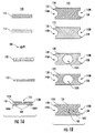
図1Aは、本開示による電気的回路保護デバイス100の分解側面図を図解する。図1Bは図1Aに描かれた電気的回路保護デバイス100の構成要素の対応する上面図を図解する。一つの実施形態において、電気的回路保護デバイス100は、第1の支持基板130を有する表面装着可能な電気的回路保護デバイスであることがある。第1の電極102Aと第2の電極102Bは、第1の支持基板130に形成及び/又は配置されていることがある。第1の電極102Aと第2の電極102Bとは、電極間隙108によって分離することができる。第1の電極102A及び第2の電極102Bは、導電性材料(例えば、銀、ニッケル、アルミニウム、プラチナ、金、亜鉛及びそれらの合金)から形成されている。第1のボンディング・パッド122は、第1の電極102A及び第2の電極102Bに配置されていることがある。第1のボンディング・パッド122は、その内部に形成された第1のキャビティ150B(例えば、キャビティ穴又は孔)を含むことがある。第2の支持基板120は、第1のボンディング・パッド122に配置されていることがある。第2の支持基板120は、その内部に形成された第2のキャビティ150A(例えば、キャビティ穴又は孔)を含むことがある。第1のキャビティ150B及び第2のキャビティ150Aは、ウェル又はキャビティ及び/又は孔を形成するために除去される材料を有することができる。第1のキャビティ150B及び第2のキャビティ150Aの組み合わせは電圧可変材料保護キャビティ150を形成することがあり(図2A−図2B参照)、これは第1のキャビティ150B及び第2のキャビティ150Aを含むことがある。第1のキャビティ150Bと第2のキャビティ150Aとの直径は、実質的に同じ寸法とすることができる。
FIG. 1A illustrates an exploded side view of an electrical
第1の電極102A及び第2の電極102Bが形成されて及び/又は第1の支持基板130に配置されると、第1の電極102Aと第2の電極102Bとは「エッジ間(edge−to−edge)」方式で互いから隔てられて、電極間隙108を形成する(図2Bも参照)。換言すれば、第1の電極102A及び第2の電極102Bは、二つのエッジ間突き合わせ電極になる。一つの実施形態において、第1の電極102Aと第2の電極102Bとは、同一平面上になることがある。
When the
電圧可変材料106は、第1のキャビティ150B及び第2のキャビティ150A内に配置されて、第1の電極102A及び第2の電極102Bへ電気的に接続されることがある。第2のボンディング・パッド112は、第2の支持基板120へ配置されることがある。一つの実施形態において、第1のボンディング・パッド122及び第2のボンディング・パッド112は、電気絶縁基板及び/又はエポキシ層であることがある。第3の支持基板110は、第2のボンディング・パッド112に配置されていることがある。一つの実施形態において、第1の支持基板130、第2の支持基板120、及び第3の支持基板110は、第1の支持基板130、第2の支持基板120、及び第3の支持基板110の各々の反対縁140A、140B(即ち、電圧可変材料106を収納する内部領域に比べて最も外側の縁)にキャスタレーション138を含む。
The
電圧可変材料保護キャビティ150の大きさは様々な予め定められた寸法(例えば、深さ及び/又は直径)とし得ることに留意されたい。例えば、一つの実施形態においては、電圧可変材料保護キャビティ150は、直径約0.020インチ(0.508 mm)とされることがある。一つの実施形態において、電圧可変材料保護キャビティ150は、直径約0.025インチ(0.635 mm)であるか、より大きいことがある。電圧可変材料保護キャビティ150の寸法が増大するにつれて、電圧可変材料106を包囲して形成されたエア・ギャップ(又は、図4における電圧可変材料保護キャビティ穴450により明らかに示されたように、エア・ギャップは電圧可変材料106を完全に囲むことがある)はより大きくなる。そのように、電圧可変材料保護キャビティ150の直径が増大すると、絶縁抵抗(IR)不具合の虞を増大させるより小さな直径の電圧可変材料保護キャビティ150と比べて、IR不具合についての虞が低減される。また、電圧可変材料保護キャビティ150の大きな直径は、ステンシル開口寸法を通じて被覆させる電圧可変材料を依然として調整しながら、電圧可変材料106の配列のためにより多くの余地を可能とする。
Note that the size of the voltage variable
幾つかの実施形態において、電圧可変材料(voltage variable material:VVM)106は、第1と第2の電極102A−B間の間隙を実質的に充填することができる。キャビティの一部は、VVM 106で充填することができる。これに代えて、可変材料保護キャビティ150の一部はVVM 106を充填せずに残して、VVM 106が電極間隙108並びに第1及び第2の電極102A-B上に形成された可変材料保護キャビティ150を完全に充填しない若しくは覆わないようにすることができる。可変材料保護キャビティ150を形成する第1及び第2の電極102A−B上に位置した一つ以上の層の上に、一つ以上の更なる層又は基板を配置することができる。一つ以上の更なる層又は基板は、結合剤若しくはボンディング剤層を含むことができる。
一つ以上の更なる層又は基板は、電気的回路保護デバイス100のカバーを形成することができる。即ち、一つ以上の更なる層又は基板は、VVM 106を包含する可変的材料保護キャビティ150を封止することができる。一つ以上の更なる層又は基板がキャビティを封止して、VVM 106を配置してこれが可変材料保護キャビティ150を充填しないようにしてから、一つ以上の更なる層と可変材料保護キャビティ150に配置されたVVM 106との間に間隙若しくは空隙を設けることができる。
In some embodiments, a voltage variable material (VVM) 106 can substantially fill the gap between the first and
One or more additional layers or substrates may form a cover for the electrical
一つ以上の更なる層又は基板は、電気的回路保護デバイス100のための堅固なカバーを形成することができる。回路保護デバイスの堅固なカバーは、VVM 106を包含して、且つこのVVM 106を一つ以上の更なる層から分離している間隙を含んでいる可変材料保護キャビティ150の完全な状態を保護することができる。可変材料保護キャビティ150内の間隙を維持して、VVM 106が可変材料保護キャビティ150の全体を充填しないようにすることによって、電気的回路保護デバイス100の性能を向上させることができる。具体的には、回路保護デバイスの絶縁抵抗は、複数の電圧パルスに亘って改善することができる。
One or more additional layers or substrates can form a rigid cover for the electrical
特定の実施形態に、可変材料保護キャビティ150は、0.020インチ(0.508 mm)又はそれより大きい(例えば、0.025インチ[0.635 mm])の直径を有することができる。特定の実施形態においては、VVM 106は電極102A-Bの間隙上で、薄い層として(例えば、0.006インチ[0.1524 mm]の厚さ又はそれより小さい、例えば0.002インチ[0.508 mm]の厚さを有する薄いステンシル層として)の可変材料保護キャビティ150内に配置することができる。特定の実施形態において、VVM 106は、電極102A-B間の電極間隙108内及び可変材料保護キャビティ150内に配置されており、電極102A−Bの下側には配置されていない。特定の実施形態において、VVM 106は可変材料保護キャビティ150を充填せず、その代わりに、VVM 106と可変材料保護キャビティ150の壁(第1及び第2の電極102A−B上に配置された一つ以上の層により形成されている)と可変材料保護キャビティ150の堅固なカバー(キャビティ上に配置された一つ以上の層又は基板により形成されている)との間に間隙若しくは空隙を設ける。
In certain embodiments, the variable
更に、幾つかの実施形態においては、第1のボンディング・パッド122と第2のボンディング・パッド112は、第1のボンディング・パッド122及び第2のボンディング・パッド112の対向縁140A、140Bにおけるキャスタレーション138を含み得る。一つの実施形態において、第1の支持基板130、第2の支持基板120、第3の支持基板110、第1のボンディング・パッド122、及び第2のボンディング・パッド112の対向縁140A、140Bにおけるキャスタレーション138は、穿孔処理を介して形成されることがある。キャスタレーション138は、電気的回路保護デバイス100の各々の層について実質的に同様であり、その切り欠きは、各々の層が互いに他の層に積み重ねられるにつれて、各々の層に亘って整合されることがある。
Further, in some embodiments, the
対向縁140A、140Bは、第1の支持基板130、第2の支持基板120、第3の支持基板110、第1のボンディング・パッド122及び第2のボンディング・パッド112の縦方向端部になることがある。対向縁140A、140Bにおけるキャスタレーション138は、穿孔によって形成し得る。第1の支持基板130、第2の支持基板120、第3の支持基板110、第1のボンディング・パッド122及び第2のボンディング・パッド112の対向縁140A、140Bのような縦方向端部は、銅又は他の導電性材料(又は金属)で、例えば、組み立てられた電気的回路保護デバイス100の第1の電極102A及び第2の電極102Bの電気的接続を促進するフォトリソグラフィ処理又は他の被覆手段により、めっきされることがある。組み立てられた電気的回路保護デバイス100の第1の電極102Aと第2の電極102Bは、外部端子(図1に104A及び104Bとして個々に示されている)へ接続されることがあり、この外部端子は電気的回路保護デバイス100の対向端部の周りに部分的に巻き付くことができる。
The opposing edges 140A and 140B are longitudinal ends of the
外部端子10A及び104Bは、第1の電極102A及び第2の電極102Bに物理的且つ電気的に接触することができる。一つの実施形態においては、外部端子104Aは第1の電極102Aと物理的且つ電気的に接触することがあると共に、他方の外部端子104Bは第2の電極102Bとは物理的に隔絶されて且つ電気的に接触することがある。代替的実施形態においては、外部端子104A及び104Bは、第1の電極102Aと第2の電極102Bとの両方へ結合された一つの特異な端子であることがある。
The
幾つかの実施形態において、電気的回路保護デバイス100は印刷回路(PC)基板に何れの側にも装着されることがある。というのは外部端子104A及び104Bは、電気的回路保護デバイス100の一部の周りに巻き付くことができ、電気的回路保護デバイス100を対称形にするためである。これは、PC基板における方位付けがしばしば困難であるより小型なデバイスについて有益である。
In some embodiments, the electrical
更に、図1A−図1Bに描かれた電気的回路保護デバイス100は、第3の支持基板110(例えば堅固なカバー)を持たせることにより、より頑強な設計の利益を与える。第3の支持基板110は、電気的回路保護デバイス100の組み立て及び/又は操作の間に生じるボンディング及び/又は押圧操作の間に電圧可変材料106の上及び/又は上方に配置若しくは位置されるときに、電圧可変材料106の接触又は圧縮を防止し得る。第3の支持基板110が電圧可変材料106に接触及び/又は圧縮するのを防止することによって、電気的回路保護デバイス100により示されているIR不具合又はIRシフトを低減することができる。更なる利点は、例えば、電磁パルス、静電放電、他の電子機器機又は電子部品により誘導されたものからのパルスに繰り返し晒されるIRの改善である。
Further, the electrical
図2Aは、電気的回路保護デバイス100の組立ての段階を示す側面断面図を図解する。図2Bは、図2Aに描かれた電気的回路保護デバイス100の対応する斜視上下図を図解する。更に具体的には、図2A-2Bは、電気的回路保護デバイス100の様々な視点200、202、204、206、及び208を図解する。ここに例示されるように、図2A-2Bは、電気的回路保護デバイス100の組立ての様々な段階を描く。視点200は、可変材料保護キャビティ150を伴わずに部分的に組み立てられた電気的回路保護デバイス100である。視点206は、側面図200の上面図に対応することができる。視点202は、電圧可変材料保護キャビティ150の形成を示すことができる。視点204は、電圧可変材料保護キャビティ150の範囲内の電圧可変材料106の位置を示すことができる。視点208は、側面図204の上面図に対応することができる。
FIG. 2A illustrates a side cross-sectional view illustrating the stages of assembly of the electrical
視点200は、第1の支持基板130に形成及び/又は配置された第1の電極102A及び第2の電極102Bの上に層状にされた第2の支持基板120及び第1のボンディング・パッド122を描くアセンブリの段階を図解する。一つの実施形態においては、第1の電極102A及び第2の電極102Bが第1の支持基板130にボンディング及び/又は形成される後に、ボンディング又は押圧操作を実行して第1の電極102A及び第2の電極102Bを、第1のボンディング・パッド122を有する第2の支持基板120へボンディングさせ得る。第1の電極102A及び第2の電極102Bが第1の支持基板130に形成及び/又は配置されたとき、第1の電極102A及び第2の電極102Bは互いから分離されて、「エッジ間(edge−to−edge)」方式で互いに突き合わされて、電極間隙108を形成するようにし得る。換言すれば、第1の電極102Aと第2の電極102Bは、二つのエッジ間突き合わせ電極になることができる。
The
図1A−図1B及び図2A−図2Bに示されたような電極間隙108は、可変材料保護キャビティ150の底部部分を形成することがある。電極間隙108は第1の電極102Aと第2の電極102Bとの間に形成し得る。一つの実施形態においては、電極間隙108は、フォト・リソグラフィック/電解析出処理を介して形成される。第1の電極102A及び第2の電極102Bは同一平面上にされることがあり、電極間隙108がウェル又はキャビティを形成する。幾つかの実施形態においては、電極間隙108は幾何学的形態及び寸法を有して、電圧可変材料106の少なくとも一部を電極間隙108内に配置させるようにすることがある。
The
電極間隙108は、二つのエッジ間突き合わせ電極、例えば第1の電極102Aと第2の電極102Bとの間に形成されることがあり、これらの電極は、支持基板、例えば第1の支持基板130に個別に配置されている。第1の電極102A及び第2の電極102Bの内端縁141A、141Bは活性電極領域を形成する。第1の電極102Aと第2の電極102Bは、電圧可変材料106と接触する電極の部分として、第1の電極102Aと第2の電極102Bの活性領域を有する比較的に大きな領域を占めることがある。更に、特定のアプリケーションのための電圧の適切な分流を得るために、第1の電極102Aと第2の電極102Bの内端縁141A、141Bの間の電極間隙108は、製造仕様に従って予め定められて規定され、及び/又は実質的に二(2)ミル(0.0508 ミリメートル)又は三(3)ミル(0.0762 ミリメートル)(ミルはインチの1000分の1である)にされることがある。第1の電極102Aと第2の電極102Bは、従来のフォト・リソグラフィック/電解堆積処理を用いて、第1の支持基板130の表面の一方へ適用される。第1の電極102Aと第2の電極102Bと第1の支持基板130との間の良好な接続を確実にするために、第1の支持基板130は、最初に洗浄される。更に、電気的回路保護デバイス100のための組み立ての操作の前に、第1の支持基板130、第2の支持基板120、及び第3の支持基板110は、最初に洗浄されることがある。
The
第1の支持基板130として用いるのに好ましい材料は、FR-4エポキシ、ポリイミド、及びセラミックを含む。C-段階に硬化するFR-4エポキシは特に好まれる。また、第1の支持基板130、第2の支持基板120、及び第3の支持基板110は、両側に銅(Cu)被覆を伴わないFR−4とされることがある。フォト・レジスト材料が第1の支持基板130の表面に施されることがある。ステンシル又はマスクはフォト・レジスト材料に施されて、マスクされていない材料は硬化又は現像される。第1の電極102A及び第2の電極102Bを収容するように表面の部分を覆うフォト・レジスト材料(即ち、未硬化材料)は、はぎ取られるか、すすぎ落とされることがある。次いで、第1の電極102A及び第2の電極102Bは、第1の支持基板130の内部の露呈した表面へ適用される。望ましくは、銅(Cu)は電解沈殿を介して第1の支持基板130の表面に適用されることがある。しかしながら、幾つかの導電性材料(例えば、金属)を第1の電極102A及び第2の電極102Bを形成するのに用いることができ、これは例えば、銀、ニッケル、アルミニウム、プラチナ、金、亜鉛及びそれらの合金である。第1の電極102Aと第2の電極102Bが第1の支持基板130へ適用された後、残留する硬化されたフォト・レジスト材料は材料を化学槽へ露呈することにより除去し得る。
Preferred materials for use as the
視点202及び206は、可変材料保護キャビティ150の形成を描く組み立ての次の段階を図解する。視点202及び206で描かれる組み立ての段階は、視点200で描かれる組み立ての段階に続く段階となることができる。可変材料保護キャビティ150は、第1のボンディング・パッド122と第2の支持基板120の部分を除去することによって形成することができる。例えば、可変材料保護キャビティ150は、第1の電極102A及び第2の電極102Bの上に層をなす第2の支持基板120及び第1のボンディング・パッド122の外側部分を穿孔することにより形成することができる。第1のボンディング・パッド122及び第2の支持基板120から材料を除去することにより、キャビティ又は穴(即ち、可変材料保護キャビティ150)が形成される。
視点204及び対応する視点2068は、視点202及び対応する視点206に示される組み立ての段階に続く組み立ての更なる段階を示す。視点204及び208に示されるように、少なくとも一部の電圧可変材料106は、可変材料保護キャビティ150へ及び電極間隙108に被覆されることがある。可変材料保護キャビティ150は、電圧可変材料106を、可変材料保護キャビティ150及び電極間隙108に被覆された後に、電気的回路保護デバイス100のボンディング、押圧、及び/又は組立ての間に圧迫されるのを防ぐ。電圧可変材料106は、第1の電極102Aと第2の電極102Bとの上に配置することができる。
各々が第1の電極102Aと第2の電極102Bの上で層状にされた後、ボンディング・パッド122と第2の支持基板120の部分を除去することにより可変材料保護キャビティ150を形成することに代わるものとして、第1の電極102Aと第2の電極102Bの上へ階層化されるのに先立って、第2の支持基板120と第1のボンディング・パッド122の外側部分を穿孔することによって電圧材料保護キャビティを形成することができる。従って、電圧可変材料106を被覆させることは、ステンシル印刷を介して生じることがあるか、及び/又は、第2の支持基板120と第1のボンディング・パッド122とが第1の電極102Aと第2の電極102Bの上に組み立てられるのに先立って及び/又はそれと同時にステンシル印刷を介して被覆されることがある。
Forming the variable
ここに説明されるように、視点200、202、204、206、及び208は電気的回路保護デバイス100の組立ての異なる段階の特定の詳細を強調することを意図している。例えば、電極間隙108を予め定められた寸法の絶縁、導電性、又は半導電性粒子を有する電圧可変材料106で充填することにより、電圧可変材料106の特性は、電極間隙108の間隔と併用されて、抵抗の変化を通じてEOS保護を提供する。例えば、電圧可変材料106の抵抗は変化する電圧レベルの関数であることがあり、例えば、電圧が増大するにつれて低い抵抗を持ちながら、低電圧のために高い抵抗を持つ。このように、電圧可変材料106は過剰電圧又は電流の一部を分路し得るので、それにより電気的回路とその構成要素を保護する。危険な過渡電流の大部分は、危険の源へ向かって反射して戻すことができる。反射された過度電流波は、源によって減衰されるか、放射されるか、サージ保護デバイスへ再指向されて戻され、これは危険なエネルギが安全レベルへ低減されるまで、各々の復帰パルスにより応答する。
As described herein,
電極間隙108と可変材料保護キャビティ150は、電圧可変材料106が、ボンディングされた第2のボンディング・パッド112を有する第3の支持基板110をボンディング及び/又は押圧すると、如何なる接触、圧力、又は圧縮が除去又は低減される方式で配置されることを可能にする。換言すれば、保護キャビティ、例えば第1のキャビティ150Bは、如何なるボンディング又は押圧組み立て作業、及び/又は如何なる後続の処理の間にも電圧可変材料106を押圧から防ぐ。
The
図3Aは、本開示による電気的回路保護デバイス100の最終的な組立てを描く断面側面図を図解する。図3Bは、完全に組み立てられた電気的回路保護デバイス100の上面及び底面図を図解する。とりわけ、図3A−3Bは、電気的回路保護デバイス100の様々な視点302、304、306、及び308を図解する。視点302は、第3の支持基板110、例えば電気的回路保護デバイス100の堅固なカバー(第2のボンディング・パッド112を含む)の断面側面図を描く。視点304は、第3の支持基板110、例えば可変材料保護キャビティ150の上に置かれて、第2の支持基板120へボンディングされた堅固なカバー(第2のボンディング・パッド112を含む)を有する組み立てられた電気的回路保護デバイス100の断面側面図を描く。視点306は組み立てられた電気的回路保護デバイス100の上面図を描くと共に、第3の支持基板110と反対縁におけるキャスタレーションとを示す。視点308は組み立てられた電気的回路保護デバイス100の底面図を描くと共に、底部基板、例えば第1の支持基板130と、反対縁140A、140Bにおけるキャスタレーション138とを示す。ここに説明されるように、視点302、304、306、及び308は最終的な組み立てられた電気的回路保護デバイス100の特定の詳細を強調することを意図している。
FIG. 3A illustrates a cross-sectional side view depicting the final assembly of the electrical
ボンディング及び/又は押圧操作は第3の支持基板110を第2のボンディング・パッド112へボンディングするために実行し得る。ボンディング剤が用いられることがあり、第3の支持基板110へ事前硬化させることがある。第3の支持基板110は、「堅固なカバー」を形成し、第1のボンディング・パッド122を有する第2の支持基板120へボンディングされる。基板110により形成された第3の支持基板110、例えば堅固なカバーと第2のボンディング・パッド112とは、電圧可変材料保護キャビティ150を覆い、電圧可変材料106を如何なるボンディング又は押圧組み立て作業、及び/又は何らかの以降の処理、例えば電気的回路保護デバイス100の使用又は作動の間の押圧から更に防止する。一つの実施形態において、第1のキャビティ150B及び第2のキャビティ150Aは(図1A−図1Bに示すように)一緒に電圧可変材料保護キャビティ150を形成し、電圧可変材料106を如何なるボンディング又は押圧組み立て作業、及び/又は何らかの以降の処理又は作業の間の押圧から保護する。
A bonding and / or pressing operation may be performed to bond the
図4は、本開示による代替的な電気的回路保護デバイス400を図解する。
図4は、電気的回路保護デバイス400の様々な部分の様々な視点を示す。例えば、視点452は電気的回路保護デバイス400の最下層を示す。視点458は、組み立てられた電気的回路保護デバイス400の側面図を示す。視点454は、視点458に描かれた最終的に組み立てられた電気的回路保護デバイス400を形成するように電気的回路保護デバイス400の最下層上に配置された様々な材料、層又は構成要素を示す。
FIG. 4 illustrates an alternative electrical
FIG. 4 shows various perspectives of various portions of the electrical
図4で示すように、視点452は、支持基板430、第1及び第2の電極402A、402B、及び電極間隙408がある電気的回路保護デバイス400の組み立てられた底部部分を示す。
As shown in FIG. 4,
視点454は、堅固なカバーとして機能している支持基板410、ボンディング・パッド412、電圧可変材料406を示す。電圧可変材料406は、第1及び第2の電極402A、402Bの上に被覆することができる。次いで支持基板410及びボンディング・パッド412は、視点458で示すように電圧可変材料406と第1及び第2の電極402A、402Bの上に配置することができる。
ボンディング・パッド412及び支持基板410は、支持基板430の上へボンディング及び/又は押圧することができる。
The
第1の電極402Aと第2の電極402Bとは、導電性材料から形成される。電極間隙108は、第2の電極402Bとの「エッジ間」に置かれる第1の電極402Aにより形成される。電極間隙408は、フォト・リソグラフィック/電解堆積処理によって形成されることがある。
The
ボンディング・パッド412は、第1の電極402A及び第2の電極402Bに配置されていることがある。電気的回路保護デバイス400は、一つのボンディング・パッドを有することがある。ボンディング・パッド412はその内部に規定された第1のキャビティ450Bを有することがあり、ボンディング・パッド412は支持基板430に配置及び接触及び/又は押圧されることがある。一つの実施形態において、第1のキャビティ450Bは、キャビティ孔若しくは開口アパーチュアを形成するために除去された材料を有することがある。
The
支持基板410は、その内部に規定された第2のキャビティ450Aを有することがある。視点458で示すように、支持基板410は、実質的に平坦な上部部分と底面とを有することがあり、その底面は屈曲若しくは弧状区画を有し、その下には電圧可変材料406が配置される。支持基板410は、「堅固なカバー」を形成し、ボンディング・パッド412へボンディングされる。第2のキャビティ450Bは、視点458に示すようにウェル又はキャビティ及び/又は開口アパーチュアを形成するように除去された材料を有することがある。
The
電圧可変材料406は、ボンディング・パッド412のキャビティ450B内で支持基板430に配置されることがあり、第1の電極402A及び第2の電極402Bへ電気的に接続される。支持基板410の底面の成形は、何らかのボンディング又は押圧組み立て作業、及び/又は何らかの以降の処理の間に電圧可変材料406が押圧されることを低減若しくは防止することができる。
The
図4に示すように、電圧可変材料406を覆う支持基板410の底面の成形は、電圧可変材料406と実質的に共形である一方、電圧可変材料406と支持基板410との間の間隙を依然として与える。第1のキャビティ450B及び第2のキャビティ450Aは電圧可変材料保護キャビティ穴450を全体的に形成し、これは、電圧可変材料保護キャビティ穴450がアーチ若しくはドーム形状を形成し、支持基板410がアーチ若しくはドーム形状を有する電圧可変材料406の形状に一致するので、「アーチ状キャビティ」と称されることがある。
As shown in FIG. 4, the molding of the bottom surface of the
電圧可変材料保護キャビティ450は、支持基板410が第1の基板に配置されているとき、電圧可変材料406と支持基板410との間に規定された空所を含む。支持基板410は、被覆された電圧可変材料406の形状に実質的に適合することができ、実質的にアーチ若しくはドーム形状を有する電圧可変材料保護キャビティ450のアーチ状キャビティ形成をもたらす。
The voltage variable
電気的回路保護デバイス400は外部端子404A及び404Bを含むことがあり、これは電気的回路保護デバイス400の反対側の周りに巻き付く。外部端子404Aと404Bとは、それぞれ第1の電極402Aと第2の電極402Bとに物理的且つ電気的に接触することができる。電気的回路保護デバイス400は、周囲に巻き付く外部端子404がデバイスを対称にするので、何れの側でもPCボードへ装着し得る。これはPCボードの方向付けがしばしば困難であるより小型なデバイスにとって有利である。
The electrical
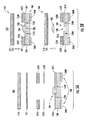
図5Aは本開示による電気的回路保護デバイス500の層状構成要素を描いている分解断面側面図を図解する。図5Bは電気的回路保護デバイス500の組立てを図解する。図5Cは完全に組み立てられた電気的回路保護デバイス500の側面図を図解する。
FIG. 5A illustrates an exploded cross-sectional side view depicting layered components of an electrical
視点560は電圧可変材料506の被覆を示し、視点555は電気的回路保護デバイス500の他の構成要素に関して被覆された電圧可変材料506を示す。図5A及び図5Bに示すように、堅固なカバー510とボンディング・パッド512とは一緒にボンディング及び/又は押圧される。更に、中間層520A−B及び522A−Bは、第1の支持基板530に配置された第1の電極502A及び第2の電極502Bの上へボンディングされる。中間層520A−B及び522A−Bの位置決めはキャビティ550(例えば、電圧材料保護キャビティ550)を形成することができる。中間層520A−Bは基板とすることができる。中間層522A−Bはボンディング層とすることができる。図5A及び図5Bに更に示されるように、堅固な第3の基板/カバー510とボンディング・パッド512は、中間層520A−Bの上部に設置及び/又は配置することができる。電圧可変材料506は、キャビティ550内で被覆することができる。電気的回路保護デバイス100とは対照的に、中間層520A−B及び522A−Bは二つの非接続区画から形成されている。換言すれば、中間層522は二つの個別の部分520A及び520Bから形成されており、一方、他方の中間層522は二つの個別のボンディング・パッド522A及び522Bから形成されている。
View 560 shows the coating of
第1の電極502A及び第2の電極502Bは、フォト・リソグラフィック又は電解被覆処理を用いて第1の支持基板530に塗布し得る。第1及び第2の電極502A及び502Bと第1の支持基板530との間の良好な接続を確実にするために、第1の支持基板530が先ず洗浄される。更に、電気的回路保護デバイス500の組み立ての作業に先立って、第1の支持基板530、第2の支持基板520、及び第3の基板510を先ず洗浄し得る。
The
第1の支持基板530として好ましい材料は、FR−4エポキシ、ポリイミド、及びセラミックを含む。C−段階へ硬化されたFR−4エポキシは、特に好ましい。また、第1の支持基板530、第2の支持基板520、及び第3の基板510は、両側における銅(Cu)被覆を伴わないFR−4とされることがある。フォト・レジスト材料は第1の支持基板530の表面へ施し得る。ステンシル又はマスクは、フォト・レジスト材料及び非マスク材料へ塗布されて、硬化又は成長し得る。第1の電極502Aと第2の電極502B(即ち、未硬化材料)を収容するために表面の部分を覆うフォト・レジスト材料は、剥がされて、すすぎ落とされる。
Preferred materials for the
次いで、第1の電極502A及び第2の電極502Bが第1の支持基板530の内部の露呈された表面へ塗布される。好ましくは、銅(Cu)が電解被覆を介して第1の支持基板530の表面へ塗布される。しかしながら、幾つかの導電性材料、例えば、銀、ニッケル、アルミニウム、プラチナ、金、亜鉛及びそれらの合金を第1の電極502A及び第2の電極502Bを形成するために用いることができることに留意されたい。第1の電極502Aと第2の電極502Bとが第1の支持基板530へ塗布された後、残留する硬化したフォト・レジスト材料は、材料を化学槽へ晒すことにより除去される。第1の電極502Aと第2の電極502Bとは、第1の支持基板530にボンディング及び/又は形成される。
Next, the
電極間隙508は、第1の電極502Aと第2の電極502Bの間に形成し得る。一つの実施形態において、電極間隙508は、フォト・リソグラフィック/電解被覆処理を介して形成される。第1の電極502Aと第2の電極502Bとは同一平面上にあることがあり、電極間隙508はウェル又はキャビティを形成する。電極間隙508(例えば、第1の電極502Aと第2の電極502Bとの間のウェル又はキャビティ)は幾何学的な構成及び寸法を持つようにして、電圧可変材料506の少なくとも一部を間隙508に配置し得るようにせねばならない。一つの実施形態においては、第1の電極502Aと第2の電極502Bとが第1の支持基板530に塗布されるにつれて、電極間隙508が形成される。
The
電圧可変材料506は、中間層520A-Bと522A−Bとの間で、且つ上部基板/層510及び512の下に形成された電圧材料保護キャビティ550に被覆し得る。電圧可変材料506の一部は、電極間隙508に収容されて配置し得る。電圧可変材料506は、電極間隙508内に配置されたとき、第1の電極502Aと第2の電極502Bとを電気的に接続する。被覆は、ステンシル印刷を介して生じることがある。二つの個別の部分520Aと520Bとは対称的に整合されて、二つの第2のボンディング・パッド522A及び522Bの上へボンディングされることがある。
The
電圧可変材料506は、二つの個別の部分520A及び520Bが対称的に整合されて二つのボンディング・パッド522A及び522Bへボンディングされる前、間及び/又は後に、及び/又は、二つの個別の部分520A及び520Bと二つの第2のボンディング・パッド522A及び522Bとが第1の電極502A及び第2の電極502Bと第1の支持基板530の最も外側区画へボンディング及び/又は押圧される前、間、及び/又は後に、電極間隙508及び電圧材料保護キャビティ550へ被覆されることがある。
The
電圧材料保護キャビティ550は、電圧可変材料506を、第3の支持基板510(それに結合された第2のボンディング512を有する)をボンディング及び/又は押圧する際に、如何なる接触、圧力又は圧縮を除外するか若しくは低減させる方式で配置させることを可能にする。換言すれば、電圧材料保護キャビティ550は電圧可変材料506を如何なるボンディング及び/又は押圧組み立て作業、及び/又は何らかの後続処理の間に、押圧又は圧縮されることを防止する。
The voltage
電気的回路保護デバイス500は外部端子504A及び504Bを含むことがあり、これは電気的回路保護デバイス500の対向端の周りに巻き付く。外側終了端504A及び504Bは第1の電極502Aと第2の電極502Bとにそれぞれ物理的に電気的接触する。電気的回路保護デバイス500は、周囲に巻き付いた外部端子504A及び504Bがデバイスを対称形にするので、何れの側からもPCボードに装着し得る。これはPCボードの方位付けがしばしば困難であるより小型なデバイスにとって有利である。
The electrical
図6は本開示による更なる代替的電気的回路保護デバイス600の組立ての断面図を図解する。処理662A−B、664A−B、及び666A−Bは、電気的回路保護デバイス600の様々な構成要素の組立てを図解する。ここに与えられた処理の各々は、望ましい選択及び/又は製造者選択に従って実行し得る。
FIG. 6 illustrates a cross-sectional view of the assembly of a further alternative electrical
処理662A−Bにおいて、第3の支持基板610は第2のボンディング・パッド612に配置されることがある。第3の支持基板610と第2のボンディング・パッド612とは、堅固なカバーを形成し得る。
In
処理664A−Bにおいて、第1の電極602Aと第2の電極602Bは、二つの第1の基板630Aの表面の一方へ従来のフォト・リソグラフィック/電解被覆処理を用いて適用される。第1の電極602Aと第2の電極602Bとは、対称に整合して、二つの第1の基板630A及び630Bに配置される。この順序は、第1の電極602A及び第2の電極602Bと二つの第1の基板630A及び630Bとの間の良好な接続を確実にし、二つの第1の基板630A及び630Bは先ず洗浄される。更に、電気的デバイス600のための組み立て作業に先立って、二つの第1の基板630A及び630B、第2の支持基板620、及び第3の支持基板610が先ず洗浄されることがある。
In
二つの第1の基板630A及び630Bは、二つの第1の基板630A及び630Bの第3の支持基板610のような底部部分の上に固定、ボンディング、及び/又は押圧された外部端子604を含む。外部端子604は、二つの第1の基板630A及び630Bの幅、深さ、寸法、及び幾何学的形態と等しくされることがあり、及び/又は二つの第1の基板630A及び630Bと異なる幅、深さ、寸法、及び幾何学的形態を有する。例えば、外部端子604は、平坦で平面的な矩形の幾何学的形状を有する。一つの実施形態においては、二つの第1の基板630A及び630Bが外部端子604の外側縁に位置して、二つの第1の基板630A及び630Bの各々の一部が外部端子604の外側縁又は区画を越えて延出するようにされている。この二つの第1の基板630Aと630Bとが互いに同一平面上にあり、一方、外部端子604は二つの第1の基板630A及び630Bに対して非同一平面上にある。そのように、電圧材料保護キャビティ650は、外部端子604の上へボンディングされた後に、二つの第2の支持基板620Aと620Bとの間に形成される。次に、電圧可変材料606の少なくとも一部は、電圧材料保護キャビティ650に被覆し得る。この被覆はステンシル印刷により生じることがある。電圧可変材料606は、第1の電極602Aと第2の電極602Bとを電気的に接続する。電圧材料保護キャビティ650は、第1の電極602A及び第2の電極602Bと外部端子と物理的且つ電気的に接触している。
The two
第1の基板630A及び630Bとして用いる好ましい材料は、FR-4エポキシ、ポリイミド及びセラミックを含む。C−段階へ硬化するFR-4エポキシは、特に好ましい。また、第1の基板630A及び630B、第2の支持基板620、並びに第3の基板610は、両側に被覆された銅(Cu)を伴わないFR-4とされることがある。フォト・レジスト材料は、第1の基板630A及び630Bの表面に塗布されることがある。ステンシル又はマスクはフォト・レジスト材料に塗布されて、露呈された材料は硬化又は成長する。第1の電極602A及び第2の電極602Bを収容するように表面の部分を覆うフォト・レジスト材料(即ち、未硬化材料)は削ぎ落とされて、すすぎ落とされる。次いで第1の電極602A及び第2の電極602Bは、第1の基板630A及び630Bの内部の露呈された表面630Cに施される。好ましくは、銅(Cu)は電解被覆を介して第1の基板630A及び630Bの表面へ塗布される。しかしながら、幾つかの導電性材料、例えば、銀、ニッケル、アルミニウム、プラチナ、金、亜鉛及びそれらの合金は、第1の電極602A及び第2の電極602Bを形成するのに用いることができることに留意されたい。第1の電極602A及び第2の電極602Bが第1の支持基板630に施された後、残留する硬化したフォト・レジスト材料は、この材料を化学槽に晒すことにより除去される。第1の電極602A及び第2の電極602Bは、第1の基板630A及び630Bにボンディング及び/又は形成される。
Preferred materials used for the
処理666A−Bにおいて、第3の支持基板610及び第2のボンディング・パッド612は、第1の電極602A及び第2の電極602Bの上へボンディング及び/又は押圧される。処理606−Bにおいて、電圧可変材料は第3の支持基板610のボンディング及び/又は押圧の際に電圧材料保護キャビティ650内に配置され、第1の電極602A及び第2の電極602Bの上にボンディングされた第2のボンディング・パッド612を有し、如何なる接触、押圧、又は圧縮が排除される。換言すれば、電圧材料保護キャビティ650は、電圧可変材料606を如何なるボンディング又は押圧組み立て作業、及び/又は何らからの後続の処理の間に押圧されることを防ぐ。
In
電気的回路保護デバイス600は、周辺巻き付き外部端子604がデバイスを対称形にするので、何れの側からもPCボードに装着し得る。これは、PCボードの方位付けがしばしば困難なより小型のデバイスにとって有益である。
The electrical
図7は本開示に従って電気的回路保護デバイスの製造方法700の実施形態のフロー図を図解する。この製造方法700は、ブロック702において開始される。例えば、実例として、図7の製造方法は、電気的回路保護デバイス100、電気的デバイス500、及び/又は電気的回路保護デバイス600を製造するために使用し得る。この製造方法700は、ブロック704へ移る。ブロック704において、第1の支持基板が設けられる。次に、製造方法700は、ブロック706において、第1の支持基板に形成された第1の電極及び第2の電極を設け、これら第1の電極及び第2の電極は導電性材料から形成されている。この製造方法700は、ブロック708において、第1及び第2の電極に配置された第1のボンディング・パッドを設け、この第1のボンディング・パッドは、その内部に形成された第1のキャビティを有する。この製造方法700は、ブロック710において、第1のボンディング・パッドに配置された第2の支持基板を設け、この第2の支持基板は、その内部に形成された第2のキャビティを有する。第1と第2のキャビティは整列することができ、一つのより大きなキャビティを形成することができる。この製造方法700は、ブロック712において、第1のキャビティ及び第2のキャビティ内に配置されて、第1の電極及び第2の電極に電気的に接続された電圧可変材料を設ける。
FIG. 7 illustrates a flow diagram of an embodiment of a method 700 of manufacturing an electrical circuit protection device in accordance with the present disclosure. The manufacturing method 700 begins at block 702. For example, by way of example, the manufacturing method of FIG. 7 may be used to manufacture the electrical
製造方法700は、ブロック714において第2の支持基板に配置された第2のボンディング・パッドを設ける。この製造方法700は、ブロック716において第2のボンディング・パッドに配置された第3の支持基板を設ける。この製造方法700は、ブロック718において終了し得る。 The manufacturing method 700 provides a second bonding pad disposed on the second support substrate at block 714. The manufacturing method 700 provides a third support substrate disposed at a second bonding pad at block 716. The manufacturing method 700 may end at block 718.
図8は本開示に従って電気的回路保護デバイスを製造する方法800の実施形態を図解する。例えば、実例として、図8の製造方法は、電気的回路保護デバイス400及び/又は電気的回路保護デバイス500を製造するのに用いられることがある。この製造方法800は、ブロック802において開始される。この製造方法800は、ブロック804へ移る。この製造方法800は、ブロック804において第1の支持基板を設ける。この製造方法800は、ブロック806において、第1の支持基板に形成された第1の電極と第2の電極とを設け、これら第1の電極と第2の電極とは導電性材料から形成されている。この製造方法800は、ブロック808において、内部に規定されたキャビティを有して第1の支持基板に配置された第2の支持基板を設ける。この製造方法800は、ブロック810において、第1の基板に且つ第2の支持基板のキャビティ内に配置されて、第1の電極及び第2の電極に電気的に接続された電圧可変材料を設ける。この製造方法800は、ブロック812において終了し得る。
FIG. 8 illustrates an embodiment of a
本開示は特定の実施形態に言及したが、説明された実施形態への幾多の修正、変更及び変化が、添付の特許請求の範囲に規定されたような本開示の分野及び範囲から逸脱することなく可能である。従って本開示は、説明された実施形態に限定されるものではなく、以下の特許請求の範囲の文言及びその均等物により規定された完全な範囲を有することが意図されている。 While this disclosure refers to particular embodiments, numerous modifications, changes and changes to the described embodiments will depart from the field and scope of this disclosure as defined in the appended claims. It is possible. Accordingly, the present disclosure is not intended to be limited to the described embodiments but is to be construed as having the full scope defined by the following claims and their equivalents.
Claims (19)
第1の支持基板と、
第1の支持基板に形成された第1の電極及び第2の電極であり、これら二つの電極は同一平面上にあり、互いに離間して端と端とが対向するようにして前記二つの電極の間に電極間隙を形成し、導電性材料から形成された第1の電極及び第2の電極と、
第1及び第2の電極に配置され、内部に形成された第1のキャビティを有する第1のボンディング・パッドと、
第1のボンディング・パッドに配置された第2の支持基板であり、第1と第2の電極を第1のボンディング・パッドを介して第2の支持基板に接着させると共に、内部に形成された第2のキャビティを有する第2の支持基板と、
前記電極間隙と、第1のキャビティと、第2のキャビティとに充填された電圧可変材料であり、この充填された電圧可変材料は第1の電極及び第2の電極に電気的に接続されて、第1のキャビティと第2のキャビティが前記充填された電圧可変材料の形状に一致するようにされている充填電圧可変材料と、
第2の支持基板に配置されて接着された第2のボンディング・パッドと、
第2のボンディング・パッドに配置されて接着された第3の支持基板とを備え、この第3の支持基板と第2のボンディング・パッドとは第1と第2のキャビティを覆う電気的回路保護デバイス。 A electrical circuit protection device,
A first support substrate;
A first electrode and a second electrode formed on the first support substrate, the two electrodes being on the same plane, the two electrodes being spaced apart from each other and facing each other; Forming an electrode gap between the first electrode and the second electrode formed of a conductive material;
A first bonding pad disposed on the first and second electrodes and having a first cavity formed therein;
A second support substrate disposed on the first bonding pad , wherein the first and second electrodes are bonded to the second support substrate via the first bonding pad and formed therein; A second support substrate having a second cavity;
A voltage variable material filled in the electrode gap, the first cavity, and the second cavity, and the filled voltage variable material is electrically connected to the first electrode and the second electrode. A filling voltage variable material in which the first cavity and the second cavity are adapted to match the shape of the filled voltage variable material;
A second bonding pad disposed and adhered to the second support substrate ;
And a third supporting substrate bonded is disposed on the second bonding pad, the third supporting substrate and the second bonding pads electrically circuit protection covering the first and second cavity device.
第1の支持基板を設け、
この第1の支持基板に第1の電極及び第2の電極を形成し、これら二つの電極は同一平面上にあり、互いに離間して端と端とが対向するようにして前記二つの電極の間に電極間隙を形成するように設け、これら第1の電極及び第2の電極は導電性材料から形成され、
これら第1及び第2の電極に配置された第1のボンディング・パッドを設け、この第1のボンディング・パッドはその内部に形成された第1のキャビティを有し、
第1のボンディング・パッドに配置された第2の支持基板を設け、第1と第2の電極を第1のボンディング・パッドを介して第2の支持基板に接着させ、この第2の支持基板はその内部に形成された第2のキャビティを有し、
前記電極間隙と、第1のキャビティと、第2のキャビティとに充填された電圧可変材料であり、この充填された電圧可変材料は第1の電極及び第2の電極に電気的に接続されて、第1のキャビティと第2のキャビティが前記充填された電圧可変材料の形状に一致するようにされている充填電圧可変材料を設け、
第2の支持基板に配置されて接着された第2のボンディング・パッドを設け、
第2のボンディング・パッドに配置されて接着された第3の支持基板を設け、この第3の支持基板と第2のボンディング・パッドとは第1と第2のキャビティを覆うことを含む方法。 A method of forming an electrical circuit protection device comprising:
Providing a first support substrate;
A first electrode and a second electrode are formed on the first support substrate, the two electrodes are on the same plane, and are spaced apart from each other so that the ends face each other. The first electrode and the second electrode are formed of a conductive material so as to form an electrode gap therebetween,
Providing a first bonding pad disposed on the first and second electrodes, the first bonding pad having a first cavity formed therein;
A second support substrate disposed on the first bonding pad is provided, and the first and second electrodes are bonded to the second support substrate through the first bonding pad. Has a second cavity formed therein,
A voltage variable material filled in the electrode gap, the first cavity, and the second cavity, and the filled voltage variable material is electrically connected to the first electrode and the second electrode. Providing a filling voltage variable material in which the first cavity and the second cavity are adapted to match the shape of the filled voltage variable material;
Setting the second bonding pads are bonded is arranged on the second supporting substrate,
How the third supporting substrate is provided for, this third supporting substrate and the second bonding pad comprises covering the first and second cavities which are bonded are disposed on the second bonding pad.
第1の支持基板、第2の支持基板、及び第3の支持基板の各々の対向縁におけるキャスタレーションを設け、及び、
第1のボンディング・パッドと第2のボンディング・パッドとの対向縁におけるキャスタレーションを設けることを更に含む方法。 9. The method of claim 8, wherein
Providing a castellation at opposite edges of each of the first support substrate, the second support substrate, and the third support substrate; and
A method further comprising providing castellations at opposing edges of the first bonding pad and the second bonding pad .
第1の支持基板と、
第1の支持基板に形成された第1の電極及び第2の電極であり、これら二つの電極は同一平面上にあり、互いに離間して端と端とが対向するようにして前記二つの電極の間に電極間隙を形成し、導電性材料から形成された第1の電極及び第2の電極と、
第1及び第2の電極に配置されて接着され、内部に形成された第1のキャビティを有するボンディング・パッドと、
内部に規定された第2のキャビティを有すると共に前記ボンディング・パッドに配置された第2の支持基板であり、前記ボンディング・パッドを第1の支持基板と第2の支持基板との間に介在させる第2の支持基板と、及び、
前記電極間隙と、第1のキャビティと、第2のキャビティとに充填された電圧可変材料であり、この充填された電圧可変材料は第1の電極及び第2の電極に電気的に接続されて、第1のキャビティと第2のキャビティが前記充填された電圧可変材料の形状に一致するようにされている充填電圧可変材料とを備えるデバイス。 A device for electrical circuit protection,
A first support substrate;
A first electrode and a second electrode formed on the first support substrate, the two electrodes being on the same plane, the two electrodes being spaced apart from each other and facing each other; Forming an electrode gap between the first electrode and the second electrode formed of a conductive material;
A bonding pad disposed on and bonded to the first and second electrodes and having a first cavity formed therein;
A second supporting substrate disposed on the bonding pad and having a second cavity defined therein, is interposed said bonding pads between the first support substrate and second support substrate A second support substrate ; and
A voltage variable material filled in the electrode gap, the first cavity, and the second cavity, and the filled voltage variable material is electrically connected to the first electrode and the second electrode. A device having a charge voltage variable material, wherein the first cavity and the second cavity are adapted to match the shape of the filled voltage variable material.
第1及び第2のキャビティは、第2の支持基板が第1の基板に配置されているときに、前記充填された電圧可変材料と第2の支持基板との間に規定された空きスペースを有するアーチ状キャビティを形成するデバイス。 The device of claim 13, wherein the electrode gap is configured to accommodate at least a portion of the filled voltage variable material;
The first and second cavities provide a vacant space defined between the filled voltage variable material and the second support substrate when the second support substrate is disposed on the first substrate. devices that form an arch-shaped cavity having.
Applications Claiming Priority (4)
| Application Number | Priority Date | Filing Date | Title |
|---|---|---|---|
| US201562106384P | 2015-01-22 | 2015-01-22 | |
| US62/106,384 | 2015-01-22 | ||
| US14/995,881 US10181718B2 (en) | 2015-01-22 | 2016-01-14 | Surface-mountable electrical circuit protection device |
| US14/995,881 | 2016-01-14 |
Publications (2)
| Publication Number | Publication Date |
|---|---|
| JP2016154136A JP2016154136A (en) | 2016-08-25 |
| JP6438418B2 true JP6438418B2 (en) | 2018-12-12 |
Family
ID=56364745
Family Applications (1)
| Application Number | Title | Priority Date | Filing Date |
|---|---|---|---|
| JP2016009361A Active JP6438418B2 (en) | 2015-01-22 | 2016-01-21 | Surface mountable electrical circuit protection device |
Country Status (5)
| Country | Link |
|---|---|
| US (1) | US10181718B2 (en) |
| JP (1) | JP6438418B2 (en) |
| CN (1) | CN105870107A (en) |
| DE (1) | DE102016200598A1 (en) |
| TW (1) | TWI630696B (en) |
Families Citing this family (3)
| Publication number | Priority date | Publication date | Assignee | Title |
|---|---|---|---|---|
| DE102015116278A1 (en) * | 2015-09-25 | 2017-03-30 | Epcos Ag | Overvoltage protection device and method for producing an overvoltage protection device |
| CN106324922A (en) * | 2016-08-29 | 2017-01-11 | 贵州乾萃科技有限公司 | Method for quickly manufacturing functional electrode layer with needed shape on substrate |
| CN112770614A (en) * | 2020-12-07 | 2021-05-07 | 深圳顺络电子股份有限公司 | Electrostatic suppressor and manufacturing method thereof |
Family Cites Families (14)
| Publication number | Priority date | Publication date | Assignee | Title |
|---|---|---|---|---|
| US6108184A (en) * | 1998-11-13 | 2000-08-22 | Littlefuse, Inc. | Surface mountable electrical device comprising a voltage variable material |
| US6351011B1 (en) * | 1998-12-08 | 2002-02-26 | Littlefuse, Inc. | Protection of an integrated circuit with voltage variable materials |
| JP2004014466A (en) * | 2002-06-11 | 2004-01-15 | Mitsubishi Materials Corp | Chip type surge absorber and its manufacturing method |
| US7367114B2 (en) * | 2002-08-26 | 2008-05-06 | Littelfuse, Inc. | Method for plasma etching to manufacture electrical devices having circuit protection |
| JP2004127615A (en) | 2002-09-30 | 2004-04-22 | Mitsubishi Materials Corp | Surge absorber and manufacturing method of same |
| US7612976B2 (en) * | 2005-07-21 | 2009-11-03 | Cooper Technologies Company | Transient voltage protection circuit boards and manufacturing methods |
| JP5257679B2 (en) * | 2008-11-26 | 2013-08-07 | 株式会社村田製作所 | Manufacturing method of ESD protection device and ESD protection device |
| EP2352211B1 (en) * | 2008-11-26 | 2017-12-20 | Murata Manufacturing Co. Ltd. | Esd protection device and manufacturing method thereof |
| JP2010129923A (en) | 2008-11-28 | 2010-06-10 | Showa Denko Kk | Light-emitting member, light-emitting device, illumination device, backlight device and method for manufacturing light-emitting member |
| KR101439398B1 (en) * | 2010-02-04 | 2014-09-11 | 가부시키가이샤 무라타 세이사쿠쇼 | Process for producing esd protection device, and esd protection device |
| US8325002B2 (en) * | 2010-05-27 | 2012-12-04 | Advanced Semiconductor Engineering, Inc. | Power inductor structure |
| JP2013219019A (en) | 2012-03-13 | 2013-10-24 | Tdk Corp | Static-electricity countermeasure element |
| KR20140081544A (en) * | 2012-12-21 | 2014-07-01 | 에스케이하이닉스 주식회사 | semiconductor chip having protrusion, stacked package of the same and method of fabricating stacked package |
| JP6119371B2 (en) | 2013-03-28 | 2017-04-26 | 株式会社村田製作所 | ESD protection device and manufacturing method thereof |
-
2016
- 2016-01-14 US US14/995,881 patent/US10181718B2/en active Active
- 2016-01-19 DE DE102016200598.7A patent/DE102016200598A1/en active Pending
- 2016-01-21 CN CN201610164076.7A patent/CN105870107A/en active Pending
- 2016-01-21 JP JP2016009361A patent/JP6438418B2/en active Active
- 2016-01-21 TW TW105101788A patent/TWI630696B/en active
Also Published As
| Publication number | Publication date |
|---|---|
| TW201644034A (en) | 2016-12-16 |
| DE102016200598A1 (en) | 2016-07-28 |
| JP2016154136A (en) | 2016-08-25 |
| US10181718B2 (en) | 2019-01-15 |
| US20160218502A1 (en) | 2016-07-28 |
| TWI630696B (en) | 2018-07-21 |
| CN105870107A (en) | 2016-08-17 |
Similar Documents
| Publication | Publication Date | Title |
|---|---|---|
| US6693508B2 (en) | Protection of electrical devices with voltage variable materials | |
| US6108184A (en) | Surface mountable electrical device comprising a voltage variable material | |
| US6013358A (en) | Transient voltage protection device with ceramic substrate | |
| US4074340A (en) | Trimmable monolithic capacitors | |
| US6377467B1 (en) | Surface mountable over-current protecting device | |
| JP6438418B2 (en) | Surface mountable electrical circuit protection device | |
| JPH10505462A (en) | Variable voltage protection structure and method of manufacturing the same | |
| WO1998023018A1 (en) | A transient voltage protection device and method of making same | |
| US6721157B2 (en) | Electrostatic discharge device of surface mount type and fabricating method thereof | |
| US10424430B2 (en) | Module and method for manufacturing the module | |
| JP2004023103A (en) | High-voltage ball grid array (bga) package, manufacture of heat spreader for high voltage bga package, and heat spreader for high-voltage bga package | |
| US7295086B2 (en) | Dielectric component array with failsafe link | |
| KR100271992B1 (en) | Lead frame with electrostatic discharge protection and a process for making the lead frame, and a packaged semiconductor device | |
| JP2008060214A (en) | Mounting structure of laminated ceramic electronic component | |
| US5440802A (en) | Method of making wire element ceramic chip fuses | |
| WO2008069190A1 (en) | Static electricity control part and process for manufacturing the same | |
| KR20150083810A (en) | Ceramic chip fuse with offset fuse element | |
| KR20030075384A (en) | Chip scale package and the method of fabricating the same | |
| JPH09266125A (en) | Multilayer ceramic parts | |
| CN105244327A (en) | Electronic device module and method of manufacturing the same | |
| KR100495132B1 (en) | Surface mountable electrical device for printed circuit board and method of manufacturing the same | |
| JP2003124251A5 (en) | ||
| JPS6250980B2 (en) | ||
| JP2010056506A (en) | Mounting structure of electronic apparatus | |
| WO2017036511A1 (en) | Electric multilayer component for surface-mount technology and method of producing an electric multilayer component |
Legal Events
| Date | Code | Title | Description |
|---|---|---|---|
| A131 | Notification of reasons for refusal |
Free format text: JAPANESE INTERMEDIATE CODE: A131 Effective date: 20161227 |
|
| A977 | Report on retrieval |
Free format text: JAPANESE INTERMEDIATE CODE: A971007 Effective date: 20161227 |
|
| A521 | Request for written amendment filed |
Free format text: JAPANESE INTERMEDIATE CODE: A523 Effective date: 20170216 |
|
| A02 | Decision of refusal |
Free format text: JAPANESE INTERMEDIATE CODE: A02 Effective date: 20170509 |
|
| A521 | Request for written amendment filed |
Free format text: JAPANESE INTERMEDIATE CODE: A523 Effective date: 20170809 |
|
| A911 | Transfer to examiner for re-examination before appeal (zenchi) |
Free format text: JAPANESE INTERMEDIATE CODE: A911 Effective date: 20170818 |
|
| A912 | Re-examination (zenchi) completed and case transferred to appeal board |
Free format text: JAPANESE INTERMEDIATE CODE: A912 Effective date: 20170908 |
|
| A521 | Request for written amendment filed |
Free format text: JAPANESE INTERMEDIATE CODE: A523 Effective date: 20180921 |
|
| A61 | First payment of annual fees (during grant procedure) |
Free format text: JAPANESE INTERMEDIATE CODE: A61 Effective date: 20181116 |
|
| R150 | Certificate of patent or registration of utility model |
Ref document number: 6438418 Country of ref document: JP Free format text: JAPANESE INTERMEDIATE CODE: R150 |
|
| R250 | Receipt of annual fees |
Free format text: JAPANESE INTERMEDIATE CODE: R250 |
|
| R250 | Receipt of annual fees |
Free format text: JAPANESE INTERMEDIATE CODE: R250 |
|
| R250 | Receipt of annual fees |
Free format text: JAPANESE INTERMEDIATE CODE: R250 |