JP6436070B2 - Electronic equipment mounting box for vehicles - Google Patents
Electronic equipment mounting box for vehicles Download PDFInfo
- Publication number
- JP6436070B2 JP6436070B2 JP2015231119A JP2015231119A JP6436070B2 JP 6436070 B2 JP6436070 B2 JP 6436070B2 JP 2015231119 A JP2015231119 A JP 2015231119A JP 2015231119 A JP2015231119 A JP 2015231119A JP 6436070 B2 JP6436070 B2 JP 6436070B2
- Authority
- JP
- Japan
- Prior art keywords
- electronic device
- mounting box
- device mounting
- case
- box
- Prior art date
- Legal status (The legal status is an assumption and is not a legal conclusion. Google has not performed a legal analysis and makes no representation as to the accuracy of the status listed.)
- Active
Links
Images

Landscapes
- Casings For Electric Apparatus (AREA)
- Connection Or Junction Boxes (AREA)
Description
本発明は、車両用の電子機器搭載ボックスに関する。 The present invention relates to an electronic device mounting box for a vehicle.
一般に、ECU(Electronic Control Unit)等の電子機器は、車両内(例えばインストルメントパネル内)に設置された樹脂製の収納ボックス(電子機器搭載ボックス)に収納されることで車両に搭載される。電子機器搭載ボックスには、車両の標準機能に対応した電子機器に加え、車両に設定される種々のオプション機能に対応した電子機器が収納できるよう、複数の収納室が設けられている。 Generally, an electronic device such as an ECU (Electronic Control Unit) is mounted on a vehicle by being stored in a resin storage box (electronic device mounting box) installed in the vehicle (for example, in an instrument panel). The electronic device mounting box is provided with a plurality of storage chambers so that electronic devices corresponding to various optional functions set in the vehicle can be stored in addition to the electronic devices corresponding to the standard functions of the vehicle.
ここで、オプション機能に対応して搭載される電子機器には、サイズや形状が異なるものも含まれており、電子機器搭載ボックスには、それぞれのサイズや形状に応じた収納室が設けられている。このような構成によれば、オプション機能の任意の設定に応じた電子機器を搭載することができるといった利点がある。また、組み付け作業を行う作業者は設定に応じた電子機器を、対応する収納室に収納するだけで、当該電子機器の組み付け作業を行うことができるため、作業性に優れているといった利点もある。 Here, electronic devices mounted in accordance with the optional functions include those with different sizes and shapes, and the electronic device mounting box is provided with a storage room corresponding to each size and shape. Yes. According to such a configuration, there is an advantage that an electronic device according to an arbitrary setting of the optional function can be mounted. In addition, since the worker who performs the assembling work can perform the assembling work of the electronic device only by storing the electronic device corresponding to the setting in the corresponding storage room, there is an advantage that the workability is excellent. .
しかしながら、電子機器搭載ボックスに、オプション機能に対応して搭載される全てのサイズ、形状の電子機器に応じた収納室を設ける構成とした場合、以下のような問題がある。 However, when the electronic device mounting box is provided with a storage room corresponding to electronic devices of all sizes and shapes mounted in accordance with the optional function, there are the following problems.
第1に、電子機器搭載ボックスのサイズが大きくなるため、車両内の電子機器搭載ボックスの設置位置周辺における空スペースが限られてくる。 First, since the size of the electronic device mounting box increases, an empty space around the installation position of the electronic device mounting box in the vehicle is limited.
第2に、オプション機能の設定によっては、使用されない収納室が発生することとなり、電子機器搭載ボックスが、内部に不要なスペースを持つことになる。 Second, depending on the setting of the optional function, a storage room that is not used is generated, and the electronic device mounting box has an unnecessary space inside.
第3に、オプション機能に対応して搭載される電子機器のうちの一部の電子機器にサイズや形状の変更があった場合でも、電子機器搭載ボックス全体のレイアウトを設計し直す必要があり、コストがかかる。 Third, even if some of the electronic devices that are installed to support the optional functions are changed in size or shape, it is necessary to redesign the layout of the entire electronic device mounting box. There will be a cost.
このようなことから、車両に搭載される電子機器を収納する電子機器搭載ボックスにおいては、従来の利点を活かしつつ、上記問題点を改善していくことが求められている。 For this reason, in an electronic device mounting box for storing an electronic device mounted on a vehicle, it is required to improve the above problems while taking advantage of conventional advantages.
そこで、本開示は、オプション機能の任意の設定に対応可能であり、かつ、電子機器を組み付ける際の作業性に優れた車両用の電子機器搭載ボックスにおいて、サイズの縮小化、内部の不要スペースの削減ならびにコストの低減を実現することを目的とする。 Therefore, the present disclosure can cope with an optional setting of an optional function, and in a vehicle electronic device mounting box that is excellent in workability when assembling an electronic device. The purpose is to realize reduction and cost reduction.
本開示の一局面によれば、車両用の電子機器搭載ボックスは以下のような構成を有する。すなわち、
車両の第1の機能に対応する電子機器が内蔵された第1の電子機器ケースを収納する車両用の電子機器搭載ボックスであって、
前記第1の電子機器ケースを収納する収納室と、
前記電子機器搭載ボックスの側面に配置される第1の嵌合部材であって、前記車両の第2の機能に対応する電子機器が内蔵された第2の電子機器ケースを収納する筐体に配置された第2の嵌合部材を嵌合することで、該筐体を前記電子機器搭載ボックスの側面に固定する前記第1の嵌合部材と、を有し、
前記第1の嵌合部材は、前記電子機器搭載ボックスの側面において、
前記第1の電子機器ケースを前記収納室に収納する際の前記第1の電子機器ケースの移動方向と、前記筐体に配置された前記第2の嵌合部材を前記第1の嵌合部材に嵌合する際の前記筐体の移動方向とが一致するように配置されることを特徴とする。
According to one aspect of the present disclosure, a vehicular electronic device mounting box has the following configuration. That is,
An electronic device mounting box for a vehicle that houses a first electronic device case containing an electronic device corresponding to the first function of the vehicle,
A storage chamber for storing the first electronic device case;
1st fitting member arrange | positioned at the side surface of the said electronic device mounting box, Comprising: It arrange | positions in the housing | casing which accommodates the 2nd electronic device case with which the electronic device corresponding to the 2nd function of the said vehicle was incorporated. The first fitting member that fixes the housing to the side surface of the electronic device mounting box by fitting the second fitting member that is made,
The first fitting member is a side surface of the electronic device mounting box.
The moving direction of the first electronic device case when the first electronic device case is stored in the storage chamber, and the second fitting member disposed in the housing are the first fitting member. It arrange | positions so that the moving direction of the said housing | casing at the time of fitting to may correspond.
上記車両用の電子機器搭載ボックスによれば、車両の第1の機能に対応する電子機器が内蔵された第1の電子機器ケースを収納室に収納し、車両の第2の機能に対応する電子機器が内蔵された第2の電子機器ケースを収納する筐体を、電子機器搭載ボックスの側面に固定する。 According to the vehicle electronic device mounting box, the first electronic device case containing the electronic device corresponding to the first function of the vehicle is housed in the storage chamber, and the electronic device corresponding to the second function of the vehicle is stored. A housing that houses a second electronic device case containing the device is fixed to the side surface of the electronic device mounting box.
これにより、車両の第1の機能(標準機能)に対応する電子機器を車両に搭載することができる。更に、車両の第2の機能(オプション機能)に対応する電子機器を車両に搭載することが必要となった場合でも、車両の第2の機能(オプション機能)に対応する電子機器が内蔵された第2の電子機器ケースを収納する筐体を電子機器搭載ボックスに固定することで、当該第2の電子機器を車両に搭載することができる。つまり、オプション機能の任意の設定に応じた電子機器を搭載することができる。 Thereby, the electronic device corresponding to the 1st function (standard function) of a vehicle can be mounted in a vehicle. Furthermore, even when it is necessary to mount an electronic device corresponding to the second function (optional function) of the vehicle, the electronic device corresponding to the second function (optional function) of the vehicle is incorporated. By fixing the housing for housing the second electronic device case to the electronic device mounting box, the second electronic device can be mounted on the vehicle. That is, it is possible to mount an electronic device corresponding to an optional setting of the optional function.
また、電子機器搭載ボックスには第2の電子機器ケースを収納するための収納室が設けられていないため、電子機器搭載ボックスのサイズを縮小化することができる。また、使用されていない収納室が発生することもなくなるため、車両の第2の機能(オプション機能)の設定の如何によらず、電子機器搭載ボックスが内部に不要スペースを持つこともなくなる。 In addition, since the electronic device mounting box is not provided with a storage chamber for storing the second electronic device case, the size of the electronic device mounting box can be reduced. Further, since no unused storage room is generated, the electronic device mounting box does not have an unnecessary space regardless of the setting of the second function (optional function) of the vehicle.
また、上記車両用の電子機器搭載ボックスによれば、第2の電子機器ケースを収納する筐体は、第1の嵌合部材に第2の嵌合部材を嵌合することで、電子機器搭載ボックスの側面に固定される。 According to the above-mentioned vehicle electronic device mounting box, the housing for housing the second electronic device case is mounted on the electronic device by fitting the second fitting member to the first fitting member. Fixed to the side of the box.
これにより、車両の第2の機能(オプション機能)に対応する電子機器のサイズや形状が変更され、第2の電子機器ケースにおいてサイズや形状の変更が発生した場合であっても、電子機器搭載ボックス自体の設計を変更する必要がなくなり、コストを低減することが可能となる。 Thereby, even when the size and shape of the electronic device corresponding to the second function (optional function) of the vehicle are changed and the size or shape is changed in the second electronic device case, the electronic device is mounted. There is no need to change the design of the box itself, and the cost can be reduced.
また、上記車両用の電子機器搭載ボックスによれば、第1の電子機器ケースを収納室に収納する際の第1の電子機器ケースの移動方向と、筐体に配置された第2の嵌合部材を第1の嵌合部材に嵌合する際の筐体の移動方向とを一致させることができる。 Moreover, according to the said electronic device mounting box for vehicles, the moving direction of the 1st electronic device case at the time of accommodating a 1st electronic device case in a storage chamber, and the 2nd fitting arrange | positioned at a housing | casing The moving direction of the housing when the member is fitted to the first fitting member can be matched.
これにより、電子機器を車両に搭載する際の組み付け作業において、作業者は、電子機器搭載ボックスに第1の電子機器ケースを収納する作業と、第2の電子機器ケースを収納した筐体を電子機器搭載ボックスに固定する作業とを、同じ方向の作業として実施することができる。つまり、従来の組み付け作業と同様の作業を実施するだけで第1の機能に対応する電子機器及び第2の機能に対応する電子機器を車両に搭載することが可能となり、組み付け作業における従来の作業性を維持することができる。 As a result, in the assembly work when the electronic device is mounted on the vehicle, the worker can store the first electronic device case in the electronic device mounting box and the housing containing the second electronic device case electronically. The work of fixing to the equipment mounting box can be performed as work in the same direction. That is, the electronic device corresponding to the first function and the electronic device corresponding to the second function can be mounted on the vehicle simply by performing the same work as the conventional assembly work. Sex can be maintained.
本開示によれば、オプション機能の任意の設定に対応可能であり、かつ、電子機器を組み付ける際の作業性に優れた車両用の電子機器搭載ボックスにおいて、サイズの縮小化、内部の不要スペースの削減ならびにコストの低減を実現することができる。 According to the present disclosure, in an electronic device mounting box for a vehicle that can cope with an optional setting of an optional function and has excellent workability when assembling an electronic device, the size can be reduced, and an unnecessary space inside can be reduced. Reduction and cost reduction can be realized.
以下、本発明の実施形態について添付の図面を参照しながら説明する。なお、本明細書及び図面において、実質的に同一の機能構成を有する構成要素については、同一の符号を付することにより重複した説明を省く。 Hereinafter, embodiments of the present invention will be described with reference to the accompanying drawings. In addition, in this specification and drawing, about the component which has the substantially same function structure, the duplicate description is abbreviate | omitted by attaching | subjecting the same code | symbol.
[第1の実施形態]
<電子機器搭載ボックス、電子機器ケース、筐体及び他の電子機器ケースの外観構成>
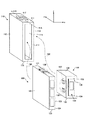
はじめに、本実施形態における車両用の電子機器搭載ボックス、電子機器ケース、筐体及び他の電子機器ケースの外観構成について説明する。図1は、車両用の電子機器搭載ボックス110、電子機器ケース120(第1の電子機器ケース)、筐体130及び他の電子機器ケース140(第2の電子機器ケース)の外観構成を示す図である。なお、図1では、電子機器搭載ボックス110の幅方向をx軸、奥行き方向をy軸、高さ方向をz軸としている。
[First Embodiment]
<Appearance configuration of electronic device mounting box, electronic device case, casing and other electronic device case>
First, the external configuration of the vehicle electronic device mounting box, the electronic device case, the housing, and other electronic device cases in the present embodiment will be described. FIG. 1 is a diagram showing an external configuration of a vehicle electronic
図1に示すように、電子機器搭載ボックス110は、上面111、下面115、左側面112、右側面113、前側面114を有しており、各面により電子機器ケース120を収納するための収納室116が形成されている。前側面114には収納口が設けられており、電子機器ケース120は、収納口を介して電子機器搭載ボックス110の収納室116に収納される。
As shown in FIG. 1, the electronic
上面111には、ボックス側抜け止め部材117が設けられている。ボックス側抜け止め部材117は、電子機器ケース120が電子機器搭載ボックス110の収納室116に収納された際に、電子機器ケース120のケース側抜け止め部材126に当接する。これにより、ボックス側抜け止め部材117は、収納された電子機器ケース120が収納室116から抜け落ちるのを防止する。
A box-
また、図1においては図示されていないが、下面115には、同様のボックス側抜け止め部材が設けられている。そして、電子機器ケース120が電子機器搭載ボックス110の収納室116に収納された際に、電子機器ケース120のケース側抜け止め部材(図1において不図示)に当接する。これにより、下面115に設けられたボックス側抜け止め部材は、収納された電子機器ケース120が電子機器搭載ボックス110の収納室116から抜け落ちるのを防止する。
Although not shown in FIG. 1, a similar box side retaining member is provided on the
なお、ボックス側抜け止め部材及びケース側抜け止め部材の詳細は、電子機器ケース120が電子機器搭載ボックス110の収納室116に収納された状態でのA−A断面を表す図6等を用いて後述する。
The details of the box-side retaining member and the case-side retaining member will be described with reference to FIG. 6 showing an AA cross section in a state where the
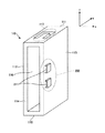
右側面113には、ボックス側嵌合部材(第1の嵌合部材)が配置されている。図2は、電子機器搭載ボックスを右側面の前方から見た場合の外観構成を示す図である。図2に示すように、右側面113には、いわゆるカセット構造のボックス側嵌合部材200が配置されており、ボックス側嵌合部材200の嵌合穴211には、筐体130の左側面132に配置された筐体側嵌合部材137(第2の嵌合部材)が嵌合される。筐体130の左側面132に配置された筐体側嵌合部材137が嵌合されることで、ボックス側嵌合部材200は、筐体130を電子機器搭載ボックス110の右側面113に固定する。
A box-side fitting member (first fitting member) is disposed on the
図1の説明に戻る。電子機器ケース120は、上面121、下面125、左側面122、右側面123、前側面124、後側面(不図示)を有しており、車両の標準機能(第1の機能)に対応するECU(Electronic Control Unit)等の電子機器を内蔵する。
Returning to the description of FIG. The
電子機器ケース120の上面121には、ケース側抜け止め部材126が設けられている。なお、上述したとおり、電子機器ケース120の下面125にも同様のケース側抜け止め部材(不図示)が設けられている。
A case-
筐体130は、上面131、下面135、左側面132、右側面133、前側面134、後側面(不図示)を有しており、各面により他の電子機器ケース140を収納するための収納室136が形成されている。前側面134には収納口が設けられており、他の電子機器ケース140は、収納口を介して収納室136に収納される。なお、他の電子機器ケース140は、車両のオプション機能(第2の機能)に対応するECU等の電子機器を内蔵する。
The
また、筐体130の左側面132には筐体側嵌合部材137が配置されており、電子機器搭載ボックス110の右側面113に配置されたボックス側嵌合部材200に嵌合することで、筐体130は、電子機器搭載ボックス110の右側面113に固定される。
Further, a housing
このように、本実施形態では、車両の標準機能に対応するECU(標準ECU)を電子機器搭載ボックス110に収納する一方で、車両のオプション機能に対応するECU(オプションECU)を、電子機器搭載ボックス110の側面に固定する。このため、本実施形態によれば、オプション機能の設定に応じて、電子機器搭載ボックス110の側面に固定するオプションECUを適宜入れ替えることが可能となる。この結果、オプション機能の任意の設定に対応するオプションECUを車両に搭載することが可能となる。
Thus, in the present embodiment, the ECU (standard ECU) corresponding to the standard function of the vehicle is housed in the electronic
また、図1に示すように、組み付け作業を行う作業者は、電子機器ケース120を、点線矢印150に沿って電子機器搭載ボックス110の収納室116に収納し、筐体130を、点線矢印160に沿って電子機器搭載ボックス110の右側面113に固定する。
Further, as shown in FIG. 1, the worker who performs the assembling work stores the
ここで、電子機器ケース120を電子機器搭載ボックス110の収納室116に収納する際の作業者による組み付け作業において、作業者が電子機器ケース120を移動させる移動方向(収納方向)は、y軸に略平行な方向である。
Here, in the assembly work by the worker when the
また、筐体130を電子機器搭載ボックス110に固定する際の作業者による組み付け作業において、作業者が筐体130を移動させる移動方向(嵌合方向)は、y軸に略平行な方向である。つまり、収納方向と嵌合方向とは一致している。換言すると、ボックス側嵌合部材200は、嵌合方向が、収納方向と一致するように、電子機器搭載ボックス110の右側面113に配置されている。
Further, in the assembly work by the worker when fixing the
このように、電子機器ケース120の収納方向と、筐体130の嵌合方向とを一致させることで、組み付け作業における優れた作業性を維持することができる。
Thus, the workability | operativity in the assembly | attachment operation | work can be maintained by making the accommodation direction of the
なお、上記説明では、標準ECUは1つのみ搭載されるものとし、電子機器搭載ボックス110には、収納室を1つのみ設けることとしているが、標準ECUは2つ搭載されてもよい。この場合、電子機器搭載ボックス110には、収納室が2つ設けられることになる。つまり、電子機器搭載ボックス110に設けられる収納室の数は、搭載する標準ECUの数に対応しているものとする。
In the above description, only one standard ECU is mounted, and the electronic
また、上記説明では、筐体130は、電子機器搭載ボックス110の右側面113に固定されるものとしたが、筐体130は、電子機器搭載ボックス110の左側面112に固定されてもよい。ただし、その場合、電子機器搭載ボックス110のボックス側嵌合部材200は、左側面112に配置され、筐体130の筐体側嵌合部材137は、右側面133に配置されることになる。
In the above description, the
<従来の電子機器搭載ボックスとの比較>
続いて、本実施形態の電子機器搭載ボックス110について、従来の電子機器搭載ボックスと比較しながら説明する。
<Comparison with conventional electronic equipment box>
Subsequently, the electronic
(1)従来の電子機器搭載ボックス
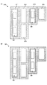
はじめに、従来の電子機器搭載ボックスについて説明する。図3は、従来の電子機器搭載ボックスの一例を示す図であり、電子機器搭載ボックスを正面から見た様子を示している。
(1) Conventional Electronic Equipment Mounted Box First, a conventional electronic equipment mounted box will be described. FIG. 3 is a diagram illustrating an example of a conventional electronic device mounting box, and illustrates a state in which the electronic device mounting box is viewed from the front.
図3(a)に示すように、従来の電子機器搭載ボックス310は、標準ECUを収納するための収納室311と、オプションECUを収納するための収納室312〜315とを有する。
As shown in FIG. 3A, the conventional electronic
図3(a)の例は、標準ECUが内蔵された電子機器ケース120が収納室311に収納され、オプションECUが内蔵された電子機器ケース140が収納室314に収納された様子を示している。
The example of FIG. 3A shows a state in which an
このように、従来の電子機器搭載ボックス310は、オプションECUのサイズや形状が様々であることに鑑みて、それぞれのサイズや形状に応じた複数の収納室312〜315を有している。このような構成とすることにより、従来の電子機器搭載ボックスは、オプション機能の設定に応じたオプションECUを搭載することができる。また、設定に応じたオプションECUが内蔵された電子機器ケースを、収納室312〜315のいずれかに収納することで、オプションECUを組み付けることができることから、従来の電子機器搭載ボックスは優れた作業性を有している。
As described above, the conventional electronic
一方で、従来の電子機器搭載ボックス310の場合、電子機器ケース140に内蔵されたオプションECUの機能以外のオプション機能について設定がなされなかったとすると、収納室312、313、315に電子機器ケースが収納されない。つまり、従来の電子機器搭載ボックス310の場合、オプション機能の設定によっては、使用されない収納室312、313、315が発生することとなり、内部に不要なスペースを持つことになる。
On the other hand, in the case of the conventional electronic
加えて、従来の電子機器搭載ボックス310の場合、オプションECUのサイズ変更があった場合に、その影響を受けることになる。
In addition, in the case of the conventional electronic
図3(b)は、従来の電子機器搭載ボックス310において、オプションECUのサイズ変更に伴いオプションECUが内蔵された電子機器ケース140のサイズが変更され、新たに電子機器搭載ボックス320が生成された様子を示している。
FIG. 3B shows that in the conventional electronic
図3(b)に示すように、電子機器ケース330を収納可能な電子機器搭載ボックス320を生成するためには、電子機器搭載ボックス310全体のレイアウトについて設計し直す必要がある。
As illustrated in FIG. 3B, in order to generate the electronic
つまり、従来の電子機器搭載ボックス310の場合、収納するオプションECUのうちの一部のオプションECUにおいてサイズ変更等が発生した場合に、電子機器搭載ボックス310全体を設計し直す必要があった。このため、コストがかかるという問題があった。
That is, in the case of the conventional electronic
(2)本実施形態の電子機器搭載ボックスの場合
次に、本実施形態の電子機器搭載ボックスについて説明する。図4は、本実施形態の電子機器搭載ボックスの一例を示す図であり、筐体が固定された電子機器搭載ボックスを正面から見た様子を示している。
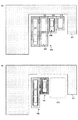
(2) In the case of the electronic device mounting box of this embodiment Next, the electronic device mounting box of this embodiment will be described. FIG. 4 is a diagram illustrating an example of the electronic device mounting box according to the present embodiment, and illustrates a state in which the electronic device mounting box with the housing fixed is viewed from the front.
図4(a)に示すように、本実施形態によれば、標準ECUが内蔵された電子機器ケース120が収納室116に収納され、オプションECUが内蔵された電子機器ケース140を収納する筐体130が、電子機器搭載ボックス110の右側面113に固定される。このため、電子機器搭載ボックス110に、使用されない収納室が発生することはなく、また、内部に不要なスペースを持つこともない。
As shown in FIG. 4A, according to the present embodiment, the
加えて、電子機器搭載ボックス110の場合、オプションECUのサイズが変更されても影響を受けることがない。
In addition, in the case of the electronic
図4(b)は、電子機器搭載ボックス110において、オプションECUのサイズ変更に伴い、オプションECUが内蔵された電子機器ケース140のサイズが変更された様子を示している。
FIG. 4B shows a state in which the size of the
図4(b)に示すように、電子機器ケース330を収納するための筐体については設計し直し、新たに筐体410を生成する必要があるものの、電子機器搭載ボックス110については、設計し直す必要がない。ボックス側嵌合部材200に嵌合するように筐体410に筐体側嵌合部材417を配置することで、筐体410を電子機器搭載ボックス110に固定することができるからである。
As shown in FIG. 4B, although the housing for housing the
つまり、電子機器搭載ボックス110の場合、オプションECUのうちの一部のオプションECUにおいてサイズ変更等が発生した場合でも、電子機器搭載ボックス110自体を設計し直す必要はなく、コストを低減することができる。
In other words, in the case of the electronic
<従来の電子機器搭載ボックスの設置例との比較>
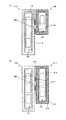
次に、図5を用いて、本実施形態における電子機器搭載ボックス110の車両内における設置例を、従来の電子機器搭載ボックス310の車両内における設置例と比較しながら説明する。図5は、従来の電子機器搭載ボックス及び本実施形態における電子機器搭載ボックスの車両内における設置例を示した図である。
<Comparison with installation example of conventional electronic equipment mounting box>
Next, an installation example of the electronic
(1)従来の電子機器搭載ボックスの設置例
はじめに、従来の電子機器搭載ボックス310の車両内における設置例について説明する。図5(a)において、領域501は、車両内において、電子機器搭載ボックス310の設置位置周辺の他の機器が占有する領域を模式的に示したものである。図5(a)に示すように、従来の電子機器搭載ボックス310の場合、オプション機能のそれぞれの設定に応じたサイズ及び形状の収納室312〜315が設けられているため、電子機器搭載ボックス310全体のサイズが大きい。このため、車両内に設置した場合に、設置位置周辺における空スペースが限られてくる。
(1) Installation Example of Conventional Electronic Device Mounting Box First, an installation example of the conventional electronic
(2)本実施形態の電子機器搭載ボックスの設置例
図5(b)は、本実施形態の電子機器搭載ボックス110の車両内における設置例を示している。図5(b)に示すように、本実施形態の電子機器搭載ボックス110の場合、電子機器ケースの収納に使用されない収納室が存在しない。このため、電子機器搭載ボックス110と筐体130とで占める領域のサイズは、電子機器搭載ボックス310全体のサイズと比較して縮小化することができる。この結果、本実施形態によれば、電子機器搭載ボックス110の設置位置周辺における空スペースを大きくすることができる(領域511参照)。
(2) Installation example of electronic device mounting box of this embodiment FIG. 5B shows an installation example of the electronic
なお、図5では、電子機器搭載ボックスのサイズについてのみ言及したが、重さについても同様である。つまり、電子機器搭載ボックス110と筐体130との合計の重さは、従来の電子機器搭載ボックス310の重さと比較して、軽量化することができる。
In FIG. 5, only the size of the electronic device mounting box is mentioned, but the same applies to the weight. That is, the total weight of the electronic
<抜け止め部材の機能の説明>
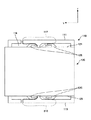
次に、本実施形態の電子機器搭載ボックス110のボックス側抜け止め部材117の機能について説明する。図6は、ボックス側抜け止め部材及びケース側抜け止め部材の詳細を示す図であり、図1のA−A断面を示したものである。
<Description of function of retaining member>
Next, the function of the box-
図6に示すように、電子機器ケース120が収納室116に収納された状態では、電子機器搭載ボックス110の上面111のボックス側抜け止め部材117が、電子機器ケース120の上面121のケース側抜け止め部材126の一方に当接する。
As shown in FIG. 6, when the
また、電子機器搭載ボックス110の下面115のボックス側抜け止め部材610が、電子機器ケース120の下面125のケース側抜け止め部材620の一方に当接する。
In addition, the box-
これにより、収納された電子機器ケース120が電子機器搭載ボックス110の収納室116から抜け落ちるのを防止することができる。
Thereby, it is possible to prevent the stored
このように、ボックス側抜け止め部材117、610は、ケース側抜け止め部材126、620とともに電子機器ケース120の抜け落ちを防止する機能を有する。
As described above, the box
<抜け止め部材の他の機能の説明>
次に、本実施形態の電子機器搭載ボックス110のボックス側抜け止め部材の他の機能について説明する。ボックス側抜け止め部材117、610は、収納室116に収納された電子機器ケース120が抜け落ちるのを防止する機能に加え、収納室116に収納する際の組み付け作業において、作業者に対して、節度感を与える機能も有する。
<Description of other functions of retaining member>
Next, another function of the box-side retaining member of the electronic
図7は、電子機器ケースを電子機器搭載ボックスの収納室に収納する際の、ボックス側抜け止め部材の動作を示した図である。図7では、電子機器搭載ボックス110のボックス側抜け止め部材117及び電子機器ケース120のケース側抜け止め部材126及びその周辺を抜粋して示している。
FIG. 7 is a diagram illustrating the operation of the box-side retaining member when the electronic device case is stored in the storage chamber of the electronic device mounting box. In FIG. 7, the box
図7(a)は、作業者が、電子機器ケース120を電子機器搭載ボックス110の収納室116に収納するために、電子機器ケース120の移動を開始した様子を示している。なお、矢印701は、電子機器ケース120の収納方向を表す。
FIG. 7A shows a state in which the worker starts moving the
図7(b)は、作業者が、電子機器ケース120を矢印701方向に移動させたことで、電子機器ケース120のケース側抜け止め部材126の一方が、電子機器搭載ボックス110のボックス側抜け止め部材117の突起部710に当接した様子を示している。
FIG. 7B shows that when the operator moves the
図7(c)は、作業者が、更に電子機器ケース120を矢印701方向に移動させることで、電子機器搭載ボックス110のボックス側抜け止め部材117が上方に曲がり、電子機器ケース120のケース側抜け止め部材126の上に乗り上げた様子を示している。
In FIG. 7C, the operator further moves the
図7(d)は、作業者が、電子機器ケース120を更に矢印701方向に移動させたことで、ボックス側抜け止め部材117の突起部710がケース側抜け止め部材126を乗り越え、電子機器ケース120の上面121に接触した様子を示している。
FIG. 7D shows that the operator further moves the
このように、作業者が電子機器ケース120を電子機器搭載ボックス110の収納室116に収納するためには、ボックス側抜け止め部材117の突起部710が、電子機器ケース120のケース側抜け止め部材126を乗り越える必要がある。つまり、作業者は、電子機器搭載ボックス110のボックス側抜け止め部材117の曲げ方向の反力に逆らった荷重により、電子機器ケース120を収納方向に押圧する必要がある。
Thus, in order for the operator to store the
ここで、電子機器搭載ボックス110のボックス側抜け止め部材117の突起部710が、電子機器ケース120のケース側抜け止め部材126を乗り越えることで突起部710が上面121に接触すると、接触音が生じる。このため、作業者は、当該接触音により電子機器ケース120が収納室116内の所定の位置に収納されたことを認識することができる。
Here, when the
このように、作業者は、ボックス側抜け止め部材117の曲げ方向の反力に応じた荷重と、突起部710の接触音とにより、節度感を得ることができる。つまり、ボックス側抜け止め部材117は、ケース側抜け止め部材126とともに、作業者に節度感を与える機能も有している。
Thus, the operator can obtain a sense of moderation by the load corresponding to the reaction force in the bending direction of the box
<電子機器搭載ボックスにおける節度感>
ここで、従来の電子機器搭載ボックス310では、POM(Polyoxymethylene)材を採用していたのに対して、本実施形態における電子機器搭載ボックス110では、POM材よりもヤング率の低い安価な材料を用いるものとする。
<Moderation in electronic equipment boxes>
Here, the conventional electronic
従来の電子機器搭載ボックス310のように、POM材を採用した場合、作業者の節度感は、上述したとおり、ボックス側抜け止め部材117の曲げ方向の反力に応じた荷重と、突起部710の接触音とにより得ることができる。
When the POM material is employed as in the conventional electronic
これに対して、ヤング率の低い安価な材料を用いた場合、接触音により節度感を実現するのは困難である。そこで、本実施形態における電子機器搭載ボックス110では、作業者の節度感を、ボックス側抜け止め部材117の曲げ方向の反力に応じた荷重により実現する。
On the other hand, when an inexpensive material with a low Young's modulus is used, it is difficult to realize a sense of moderation by contact sound. Therefore, in the electronic
作業者の節度感を荷重により実現するためには、ボックス側抜け止め部材117の曲げ方向の反力が、作業者が認識できる程度に大きいものでなくてはならない一方で、大きすぎると作業者に負担になる。このため、適切な荷重に調整する必要がある。特にヤング率の低い材料の場合、曲げ方向の反力が大きくなるため、適切な荷重に調整するためには、その増加分が、作業者の荷重の増加とならないように構成する必要がある。
In order to realize an operator's moderation feeling with a load, the reaction force in the bending direction of the box-
そこで、電子機器搭載ボックス110では、ボックス側抜け止め部材117の突起部710にテーパ部を設け、突起部710が電子機器ケース120のケース側抜け止め部材126を乗り越えやすくすることで、乗り越えるための荷重を軽減する構成とした。
Therefore, in the electronic
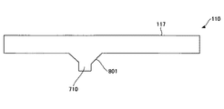
図8は、電子機器搭載ボックスにおけるボックス側抜け止め部材の突起部の形状を説明するための図である。図8に示すように、突起部710のうち、電子機器ケース120を収納方向に移動した際にケース側抜け止め部材126が当接する側の面には、テーパ部801が設けられている。このようにテーパ部801を設けることで、突起部710は電子機器ケース120のケース側抜け止め部材126を乗り越えやすくなる(乗り越えるための荷重が軽減される)。つまり、ヤング率の低い材料を用いたことで、ボックス側抜け止め部材117の曲げ方向の反力が大きくなったとしても、電子機器ケース120を収納方向に押圧する際にかかる荷重の増加は抑えることができる。
FIG. 8 is a view for explaining the shape of the protruding portion of the box-side retaining member in the electronic device mounting box. As shown in FIG. 8, a tapered
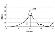
図9は、電子機器搭載ボックスに電子機器ケースを収納する際のFS(Force-Stroke)曲線の一例を示す図である。図9において、横軸は変位(mm)であり、電子機器ケース120の所定の位置からの移動量を表している。また、縦軸は、各移動量における荷重(N)を表している。
FIG. 9 is a diagram illustrating an example of an FS (Force-Stroke) curve when the electronic device case is stored in the electronic device mounting box. In FIG. 9, the horizontal axis represents displacement (mm) and represents the amount of movement of the
図9に示された2つの曲線のうち、グラフ900は、突起部710にテーパ部801が形成されたボックス側抜け止め部材117を用いた場合のFS曲線を示している。また、グラフ910は、突起部710にテーパ部801が形成されていないボックス側抜け止め部材を用いた場合のFS曲線を示している。
Of the two curves shown in FIG. 9, the
図9から明らかなように、突起部710にテーパ部801が形成されていない場合、ピーク時の荷重が大きい(70[N]を超える)のに対して、突起部710にテーパ部801が形成されていると、ピーク時の荷重を、適切な荷重(矢印参照)に抑えることができる。つまり、電子機器ケース120を電子機器搭載ボックス110に収納する際、作業者に適切な節度感を与えることができる。
As is apparent from FIG. 9, when the
<まとめ>
以上の説明から明らかなように、本実施形態における車両用の電子機器搭載ボックス110では、
・オプションECUが内蔵された他の電子機器ケースを収納する筐体に配置された筐体側嵌合部材を嵌合することで、筐体を電子機器搭載ボックスの側面に固定するボックス側嵌合部材を配置する構成とした。
・標準ECUが内蔵された電子機器ケースを収納する際の収納方向と、オプションECUが内蔵された電子機器ケースを収納する筐体を固定する際の嵌合方向とが一致するように、ボックス側嵌合部材を配置する構成とした。
<Summary>
As is clear from the above description, in the vehicle electronic
-A box-side fitting member that fixes the case to the side surface of the electronic device mounting box by fitting a case-side fitting member arranged in a case that houses another electronic device case containing the optional ECU. It was set as the structure which arranges.
-The box side so that the storage direction when storing the electronic device case with the built-in standard ECU matches the fitting direction when fixing the housing that stores the electronic device case with the built-in optional ECU. It was set as the structure which arrange | positions a fitting member.
この結果、オプション機能の任意の設定に対応可能であり、かつ、電子機器を組み付ける際の作業性に優れた車両用の電子機器搭載ボックスにおいて、サイズの縮小化、内部の不要スペースの削減ならびにコストの低減を実現することができる。 As a result, it is possible to respond to any setting of optional functions, and in the electronic equipment mounting box for vehicles with excellent workability when assembling the electronic equipment, the size is reduced, the internal unnecessary space is reduced, and the cost is reduced. Can be reduced.
[その他の実施形態]
上記第1の実施形態では、筐体130を電子機器搭載ボックス110に固定するための嵌合部材として、いわゆるカセット構造の嵌合部材を例示したが、本発明はこれに限定されない。例えば、クリップ形状の嵌合部材(車両において、ワイヤーハーネスをボデーや部品に固定する際に用いられる嵌合部材)を採用してもよい。
[Other Embodiments]
In the first embodiment, the fitting member for fixing the
具体的には、電子機器搭載ボックス110の右側面113に、ボックス側嵌合部材200として、y軸に略直交し、中央部に長穴が形成された嵌合部材を配置する。そして、筐体130の左側面132に、筐体側嵌合部材137として、ボックス側嵌合部材の長穴に嵌合されるクリップ形状の筐体側嵌合部材を配置する。
Specifically, on the
これにより、筐体130を電子機器搭載ボックス110に固定するにあたり、ワイヤーハーネスをボデーや部品に固定するのと同じ要領で固定することが可能となる。
Thereby, when fixing the housing | casing 130 to the electronic
また、上記第1の実施形態では、筐体130を電子機器搭載ボックス110に固定するためのボックス側嵌合部材200及び筐体側嵌合部材137それぞれの材質について特に言及しなかったが、それぞれの材質は、任意の組み合わせが考えられる。例えば、剛性の高い材質と剛性の低い材質とを組み合わせることで、圧入して嵌合するように構成してもよい。
In the first embodiment, the box-side
いずれの形状、材質の嵌合部材を用いた場合であっても、締結ボルトやナットを用いることなく筐体130を電子機器搭載ボックス110に固定することができるため、電子機器の組み付け作業を容易に行うことができる。
Even if a fitting member of any shape and material is used, the
なお、上記実施形態に挙げた構成等に、その他の要素との組み合わせなど、ここで示した構成に本発明が限定されるものではない。これらの点に関しては、本発明の趣旨を逸脱しない範囲で変更することが可能であり、その応用形態に応じて適切に定めることができる。 It should be noted that the present invention is not limited to the configuration shown here, such as a combination with other elements in the configuration described in the above embodiment. These points can be changed without departing from the spirit of the present invention, and can be appropriately determined according to the application form.
110 :電子機器搭載ボックス
116 :収納室
117 :ボックス側抜け止め部材
120 :電子機器ケース
126 :ケース側抜け止め部材
130 :筐体
137 :筐体側嵌合部材
140 :電子機器ケース
200 :ボックス側嵌合部材
330 :電子機器ケース
410 :筐体
710 :突起部
110: Electronic device mounting box 116: Storage chamber 117: Box side retaining member 120: Electronic device case 126: Case side retaining member 130: Housing 137: Housing side fitting member 140: Electronic device case 200: Box side fitting Joint member 330: Electronic device case 410: Housing 710: Projection
Claims (1)
前記第1の電子機器ケースを収納する収納室と、
前記電子機器搭載ボックスの側面に配置される第1の嵌合部材であって、前記車両の第2の機能に対応する電子機器が内蔵された第2の電子機器ケースを収納する筐体に配置された第2の嵌合部材を嵌合することで、該筐体を前記電子機器搭載ボックスの側面に固定する前記第1の嵌合部材と、を有し、
前記第1の嵌合部材は、前記電子機器搭載ボックスの側面において、
前記第1の電子機器ケースを前記収納室に収納する際の前記第1の電子機器ケースの移動方向と、前記筐体に配置された前記第2の嵌合部材を前記第1の嵌合部材に嵌合する際の前記筐体の移動方向とが一致するように配置されることを特徴とする車両用の電子機器搭載ボックス。 An electronic device mounting box for a vehicle that houses a first electronic device case containing an electronic device corresponding to the first function of the vehicle,
A storage chamber for storing the first electronic device case;
1st fitting member arrange | positioned at the side surface of the said electronic device mounting box, Comprising: It arrange | positions in the housing | casing which accommodates the 2nd electronic device case with which the electronic device corresponding to the 2nd function of the said vehicle was incorporated. The first fitting member that fixes the housing to the side surface of the electronic device mounting box by fitting the second fitting member that is made,
The first fitting member is a side surface of the electronic device mounting box.
The moving direction of the first electronic device case when the first electronic device case is stored in the storage chamber, and the second fitting member disposed in the housing are the first fitting member. An electronic device mounting box for a vehicle, wherein the box is arranged so that a moving direction of the housing when fitted to the housing matches.
Priority Applications (1)
| Application Number | Priority Date | Filing Date | Title |
|---|---|---|---|
| JP2015231119A JP6436070B2 (en) | 2015-11-26 | 2015-11-26 | Electronic equipment mounting box for vehicles |
Applications Claiming Priority (1)
| Application Number | Priority Date | Filing Date | Title |
|---|---|---|---|
| JP2015231119A JP6436070B2 (en) | 2015-11-26 | 2015-11-26 | Electronic equipment mounting box for vehicles |
Publications (2)
| Publication Number | Publication Date |
|---|---|
| JP2017098468A JP2017098468A (en) | 2017-06-01 |
| JP6436070B2 true JP6436070B2 (en) | 2018-12-12 |
Family
ID=58817347
Family Applications (1)
| Application Number | Title | Priority Date | Filing Date |
|---|---|---|---|
| JP2015231119A Active JP6436070B2 (en) | 2015-11-26 | 2015-11-26 | Electronic equipment mounting box for vehicles |
Country Status (1)
| Country | Link |
|---|---|
| JP (1) | JP6436070B2 (en) |
Family Cites Families (3)
| Publication number | Priority date | Publication date | Assignee | Title |
|---|---|---|---|---|
| JPH11168284A (en) * | 1997-09-30 | 1999-06-22 | Idec Izumi Corp | Electronic device housing connection mechanism |
| JP4678326B2 (en) * | 2006-04-19 | 2011-04-27 | 横河電機株式会社 | Unit connection device |
| JP6048390B2 (en) * | 2013-12-18 | 2016-12-21 | トヨタ自動車株式会社 | Mounting structure |
-
2015
- 2015-11-26 JP JP2015231119A patent/JP6436070B2/en active Active
Also Published As
| Publication number | Publication date |
|---|---|
| JP2017098468A (en) | 2017-06-01 |
Similar Documents
| Publication | Publication Date | Title |
|---|---|---|
| JP5110130B2 (en) | In-vehicle electronic control unit housing | |
| KR102610029B1 (en) | steering wheel | |
| JP7046230B2 (en) | In-module media assembly | |
| JP4244853B2 (en) | Console mounting structure | |
| JP2010167816A (en) | Casing for on-vehicle electronic control unit | |
| JP6480000B1 (en) | Electronic control device for vehicle | |
| JP2014093792A (en) | On-vehicle electronic control unit | |
| JP2005155827A5 (en) | ||
| JP6436070B2 (en) | Electronic equipment mounting box for vehicles | |
| JP6431778B2 (en) | Electric retractable door mirror for vehicles | |
| JP2012208821A (en) | Knob device | |
| JP6000472B2 (en) | Vehicle safety device control unit | |
| JP5496560B2 (en) | cover | |
| JP5563794B2 (en) | Electronic component storage box | |
| JP2010111313A (en) | Connecting structure of terminal and door mirror using the same | |
| JP5157335B2 (en) | Vehicle harness support structure | |
| JP5109315B2 (en) | Mounting structure between body panel and mounting parts for automobile, and mounting structure between rocker panel and rocker protector | |
| JP4264023B2 (en) | Car equipment | |
| JP2019216174A (en) | Vehicle electronic control device | |
| JP4930475B2 (en) | Parts protection structure during product disassembly | |
| JP5407846B2 (en) | Board mounting structure and electronic equipment | |
| KR100913261B1 (en) | Dustproof device for car external hard disk drive | |
| JP6204784B2 (en) | Connection port device | |
| JP6720793B2 (en) | Vehicle instrument panel | |
| JP2021018168A (en) | Electronic device |
Legal Events
| Date | Code | Title | Description |
|---|---|---|---|
| A621 | Written request for application examination |
Free format text: JAPANESE INTERMEDIATE CODE: A621 Effective date: 20180125 |
|
| A977 | Report on retrieval |
Free format text: JAPANESE INTERMEDIATE CODE: A971007 Effective date: 20181011 |
|
| TRDD | Decision of grant or rejection written | ||
| A01 | Written decision to grant a patent or to grant a registration (utility model) |
Free format text: JAPANESE INTERMEDIATE CODE: A01 Effective date: 20181016 |
|
| A61 | First payment of annual fees (during grant procedure) |
Free format text: JAPANESE INTERMEDIATE CODE: A61 Effective date: 20181029 |
|
| R151 | Written notification of patent or utility model registration |
Ref document number: 6436070 Country of ref document: JP Free format text: JAPANESE INTERMEDIATE CODE: R151 |