JP6000472B2 - Vehicle safety device control unit - Google Patents
Vehicle safety device control unit Download PDFInfo
- Publication number
- JP6000472B2 JP6000472B2 JP2015544848A JP2015544848A JP6000472B2 JP 6000472 B2 JP6000472 B2 JP 6000472B2 JP 2015544848 A JP2015544848 A JP 2015544848A JP 2015544848 A JP2015544848 A JP 2015544848A JP 6000472 B2 JP6000472 B2 JP 6000472B2
- Authority
- JP
- Japan
- Prior art keywords
- circuit board
- housing
- safety device
- vehicle safety
- electronic component
- Prior art date
- Legal status (The legal status is an assumption and is not a legal conclusion. Google has not performed a legal analysis and makes no representation as to the accuracy of the status listed.)
- Expired - Fee Related
Links
Images


Classifications
-
- B—PERFORMING OPERATIONS; TRANSPORTING
- B60—VEHICLES IN GENERAL
- B60R—VEHICLES, VEHICLE FITTINGS, OR VEHICLE PARTS, NOT OTHERWISE PROVIDED FOR
- B60R21/00—Arrangements or fittings on vehicles for protecting or preventing injuries to occupants or pedestrians in case of accidents or other traffic risks
- B60R21/01—Electrical circuits for triggering passive safety arrangements, e.g. airbags, safety belt tighteners, in case of vehicle accidents or impending vehicle accidents
-
- G—PHYSICS
- G01—MEASURING; TESTING
- G01P—MEASURING LINEAR OR ANGULAR SPEED, ACCELERATION, DECELERATION, OR SHOCK; INDICATING PRESENCE, ABSENCE, OR DIRECTION, OF MOVEMENT
- G01P1/00—Details of instruments
- G01P1/02—Housings
- G01P1/023—Housings for acceleration measuring devices
Landscapes
- Physics & Mathematics (AREA)
- General Physics & Mathematics (AREA)
- Engineering & Computer Science (AREA)
- Mechanical Engineering (AREA)
- Mounting Of Printed Circuit Boards And The Like (AREA)
- Regulating Braking Force (AREA)
- Vibration Prevention Devices (AREA)
Description
本発明は、車両衝突時に車両に生じた加速度を検出する加速度センサ等を搭載し、車両用安全装置を制御する車両安全装置制御ユニットに関するものである。 The present invention relates to a vehicle safety device control unit that is equipped with an acceleration sensor that detects acceleration generated in a vehicle at the time of a vehicle collision and controls a vehicle safety device.
近年、車両に生じた衝撃の方向やその度合い等に応じて駆動される車両用安全装置が開発されている。例えば車室内の様々な箇所に備えられるエアバッグや、衝撃の度合いに応じて膨張展開の度合いが制御できる多段階制御エアバッグ、または衝撃の度合いに応じて張力を調節するシートベルトプリテンショナ等が挙げられる。かかる車両用安全装置は、一般的に、電子制御ユニット(ECU:Electronic Control Unit)によって制御される。ECUは、回路基板と、回路基板に搭載され衝撃を検知する加速度センサ等の電子部品と、回路基板表面を被覆して電子部品を保護する樹脂製の筐体(ハウジング)とによって構成される。 In recent years, vehicle safety devices have been developed that are driven according to the direction and degree of impact generated in the vehicle. For example, there are airbags provided at various locations in the passenger compartment, multistage control airbags that can control the degree of inflation and deployment according to the degree of impact, or seat belt pretensioners that adjust the tension according to the degree of impact. Can be mentioned. Such a vehicle safety device is generally controlled by an electronic control unit (ECU). The ECU includes a circuit board, an electronic component such as an acceleration sensor that is mounted on the circuit board and detects an impact, and a resin casing (housing) that covers the circuit board surface to protect the electronic component.
例えば特許文献1には、車載用電子機器としての制御基板を収容する筐体が記載されている。この制御基板には、車両衝突時の加速度を検出する加速度センサが実装されている。特許文献1に記載の筐体は、ケース本体と、ケース本体の側壁から外側に延びていて車両に固定される複数のブラケットと、ケース本体の側壁とブラケットとの間にわたる複数の補強リブとを備えている。特許文献1では、この筐体によれば、車両衝突時の衝撃により制御基板が破壊されることを防止し、制御基板を確実に保護できるとしている。 For example, Patent Document 1 describes a housing that houses a control board as an in-vehicle electronic device. An acceleration sensor for detecting the acceleration at the time of a vehicle collision is mounted on the control board. The housing described in Patent Document 1 includes a case main body, a plurality of brackets extending outward from the side wall of the case main body and fixed to the vehicle, and a plurality of reinforcing ribs extending between the side wall and the bracket of the case main body. I have. In Patent Document 1, according to this housing, it is possible to prevent the control board from being destroyed by an impact at the time of a vehicle collision, and to reliably protect the control board.
特許文献2には、電子基板が筐体に固定される固定点で囲まれた三角形の領域に角速度センサと加速度センサを実装するエアバッグ電子制御装置が開示されている。特許文献2によれば、かかる領域にセンサを配置することで外部からの衝撃による振動とその振幅を低減できるとしている。 Patent Document 2 discloses an airbag electronic control device in which an angular velocity sensor and an acceleration sensor are mounted in a triangular region surrounded by a fixed point where an electronic substrate is fixed to a housing. According to Patent Document 2, it is said that vibrations caused by an impact from the outside and the amplitude thereof can be reduced by arranging a sensor in such a region.
エアバッグ等の安全装置が必要時に適切に駆動するよう、ECUの回路基板に実装された加速度センサ等の出力には信頼性が求められる。しかし車両の振動によって、加速度センサ等の電子部品の出力が不安定になるおそれがある。とりわけ加速度センサは、その姿勢の変化によって加速度の正確な検出が不可能となるため、回路基板に堅固に保持する必要がある。特許文献1または特許文献2に記載の技術によれば、外部からの衝撃によって基板上のセンサ類に加わる振動はある程度低減されると思われるが、さらに改善の余地がある。 Reliability is required for the output of the acceleration sensor or the like mounted on the circuit board of the ECU so that a safety device such as an airbag is appropriately driven when necessary. However, the output of electronic components such as an acceleration sensor may become unstable due to vehicle vibration. In particular, the acceleration sensor needs to be firmly held on the circuit board because it is impossible to accurately detect acceleration due to a change in posture. According to the technique described in Patent Document 1 or Patent Document 2, it is considered that the vibration applied to the sensors on the substrate due to an external impact is reduced to some extent, but there is still room for improvement.
本発明は、このような課題に鑑み、車両の振動による悪影響を受けにくく安定した出力が可能なセンサを搭載した車両安全装置制御ユニットを提供することを目的としている。 SUMMARY OF THE INVENTION The present invention has been made in view of the above problems, and an object of the present invention is to provide a vehicle safety device control unit equipped with a sensor that is less susceptible to adverse effects of vehicle vibration and that can output stably.
上記課題を解決するために、本発明の代表的な構成は、車両用安全装置を制御する車両安全装置制御ユニットにおいて、回路基板と、回路基板の表面または裏面に搭載されたセンサと、回路基板を被覆する筐体と、回路基板の周縁を筐体の周縁部に固定する複数の固定具と、回路基板の表面に搭載され筐体の天面方向に延び天面から突出する保持部に保持される第1の電子部品とを備え、第1の電子部品の筐体の天面に最も近い上端部を頂点とする三角錐であって、頂点から回路基板に向かう垂線の回路基板の表面との交点の角部と、複数の固定具のうち2つの固定具の位置の2つの角部から構成される三角形を底面とする三角錐の内部空間にセンサが配置されていることを特徴とする。 In order to solve the above-described problems, a typical configuration of the present invention includes a circuit board, a sensor mounted on the front or back surface of the circuit board, and a circuit board in a vehicle safety device control unit that controls the vehicle safety device. And a plurality of fixtures for fixing the peripheral edge of the circuit board to the peripheral edge of the casing, and a holding part that is mounted on the surface of the circuit board and extends in the top surface direction of the housing and protrudes from the top surface A triangular pyramid having an apex at an upper end closest to the top surface of the casing of the first electronic component, the surface of the circuit board being perpendicular to the circuit board, A sensor is arranged in an internal space of a triangular pyramid whose bottom surface is a triangle composed of a corner portion of the intersection and two corner portions at positions of two fixtures among a plurality of fixtures. .
上記構成によれば、回路基板は、複数の固定具によって回路基板の表面という平面上で筐体に固定されるだけでなく、第1の電子部品を介してさらに、筐体の天面という回路基板の表面から上方に離れた位置においても筐体に保持される。かかる保持点の追加によって回路基板の筐体に対する保持点は立体的に配置されることとなる。とりわけ、筐体の天面の第1の電子部品が保持された位置を頂点とし、2つの固定具の位置に角部を形成する三角形を底面とする三角錐の内部空間は、回路基板と筐体との間に立体的に点在する保持点で囲まれていて、保持点には制振効果が見込めるため、堅固な構造を有する。かかる三角錐の内部空間にセンサが配置されているため、センサは車両の振動による悪影響を受けにくく、安定した出力が可能となる。 According to the above configuration, the circuit board is not only fixed to the housing on a plane called the surface of the circuit board by a plurality of fixtures, but also a circuit called the top surface of the housing via the first electronic component. Even at a position away from the surface of the substrate upward, it is held by the housing. By adding such holding points, the holding points with respect to the casing of the circuit board are arranged in three dimensions. In particular, the internal space of the triangular pyramid with the position where the first electronic component on the top surface of the housing is held at the top and the triangle forming the corner at the position of the two fixtures as the bottom is the circuit board and the housing. It is surrounded by holding points that are three-dimensionally dotted with the body, and since the damping effect can be expected at the holding points, it has a solid structure. Since the sensor is arranged in the internal space of the triangular pyramid, the sensor is hardly affected by the vibration of the vehicle, and stable output is possible.
なお、筐体の天面に設けられた保持部と第1の電子部品とは、必ずしも完全に保持されていなくてもよい。それらが相対的にわずかに動くことができるような保持であっても、逆に、そのわずかな動きによって余分な振動に対する制振効果が見込めるからである。 Note that the holding portion provided on the top surface of the housing and the first electronic component are not necessarily held completely. This is because even if the holding is such that they can move relatively slightly, on the contrary, the slight movement can be expected to have a damping effect against excess vibration.
また上記構成によれば、振動吸収材などの部材を追加することなくセンサの出力を安定させることができるため、経済的にも有利である。 Moreover, according to the said structure, since the output of a sensor can be stabilized, without adding members, such as a vibration-absorbing material, it is economically advantageous.
また三角錐は、固定具の位置を底面(三角形)の角部とすることで堅固な構造となっているが、底面の残りの1つの角部の位置が三角錐の頂点から離れてしまっては、実質的に意味をなさない。その点、本発明では、上記の交点を三角形の角部としていて、これは回路基板の表面における頂点から最も近い点であるため、三角錐の内部空間は、三角錐の頂点の近傍に形成されることとなり、センサはより堅固な空間に配置されることとなる。 In addition, the triangular pyramid has a solid structure by setting the position of the fixture to the corner of the bottom surface (triangle), but the position of the remaining one corner of the bottom is separated from the apex of the triangular pyramid. Is virtually meaningless. In that respect, in the present invention, the above intersection is the corner of the triangle, and this is the point closest to the vertex on the surface of the circuit board. Therefore, the internal space of the triangular pyramid is formed near the vertex of the triangular pyramid. As a result, the sensor is arranged in a more rigid space.
第1の電子部品は、筐体の天面に最も近い上端部を2つ有し、三角錐は、2つの上端部のうち、2つの固定具からより遠い上端部を頂点とするとよい。かかる三角錐は、2つの固定具からより近い上端部による制振効果も見込め、内部空間も広くなる。 The first electronic component may have two upper end portions closest to the top surface of the housing, and the triangular pyramid may have the upper end portion farther from the two fixtures out of the two upper end portions as a vertex. Such a triangular pyramid can also be expected to have a vibration control effect due to the upper end closer to the two fixtures, and the internal space is also widened.
上記課題を解決するために、本発明の他の代表的な構成は、車両用安全装置を制御する車両安全装置制御ユニットにおいて、回路基板と、回路基板の表面または裏面に搭載されたセンサと、回路基板を被覆する筐体と、回路基板の周縁を筐体の周縁部に固定する複数の固定具と、回路基板の表面に搭載され筐体の天面方向に延び天面から突出する保持部に保持される第1の電子部品とを備え、第1の電子部品が保持された位置を頂点とする円錐であって、複数の固定具のうち第1の電子部品に近い少なくとも2つの固定具を内包する円を底面とする円錐の内部空間にセンサが配置されていることを特徴とする。 In order to solve the above problems, another typical configuration of the present invention is a vehicle safety device control unit that controls a vehicle safety device. In the vehicle safety device control unit, a circuit board, a sensor mounted on the front surface or the back surface of the circuit board, A casing that covers the circuit board, a plurality of fixtures that fix the periphery of the circuit board to the periphery of the casing, and a holding part that is mounted on the surface of the circuit board and extends from the top surface of the casing And at least two fixtures close to the first electronic component among the plurality of fixtures, the first electronic component being held in the cone, and having a vertex at the position where the first electronic component is held A sensor is arranged in an inner space of a cone whose bottom is a circle containing the.
上記構成によれば、回路基板は、複数の固定具によって回路基板の表面という平面上で筐体に固定されるだけでなく、第1の電子部品を介してさらに、筐体の天面という回路基板の表面から上方に離れた位置においても筐体に保持される。かかる保持点の追加によって回路基板の筐体に対する保持点は立体的に配置されることとなる。とりわけ、筐体の天面の第1の電子部品が保持された位置を頂点とし、少なくとも2つの固定具を内包する円を底面とする円錐の内部空間は、回路基板と筐体との間に立体的に点在する保持点で囲まれているため、堅固な構造を有する。かかる円錐の内部空間にセンサが配置されているため、センサは車両の振動による悪影響を受けにくく、安定した出力が可能となる。 According to the above configuration, the circuit board is not only fixed to the housing on a plane called the surface of the circuit board by a plurality of fixtures, but also a circuit called the top surface of the housing via the first electronic component. Even at a position away from the surface of the substrate upward, it is held by the housing. By adding such holding points, the holding points with respect to the casing of the circuit board are arranged in three dimensions. In particular, the internal space of the cone with the position where the first electronic component on the top surface of the housing is held at the top and the bottom including a circle containing at least two fixtures is between the circuit board and the housing. Because it is surrounded by three-dimensionally held holding points, it has a solid structure. Since the sensor is disposed in the inner space of the cone, the sensor is not easily affected by the vibration of the vehicle, and stable output is possible.
なお、筐体の天面に設けられた保持部と第1の電子部品とは、必ずしも完全に保持されていなくてもよい。それらが相対的にわずかに動くことができるような保持であっても、逆に、そのわずかな動きによって余分な振動に対する制振効果が見込めるからである。 Note that the holding portion provided on the top surface of the housing and the first electronic component are not necessarily held completely. This is because even if the holding is such that they can move relatively slightly, on the contrary, the slight movement can be expected to have a damping effect against excess vibration.
また上記構成によれば、振動吸収材などの部材を追加することなくセンサの出力を安定させることができるため、経済的にも有利である。 Moreover, according to the said structure, since the output of a sensor can be stabilized, without adding members, such as a vibration-absorbing material, it is economically advantageous.
上記課題を解決するために、本発明の他の代表的な構成は、車両用安全装置を制御する車両安全装置制御ユニットにおいて、回路基板と、回路基板の表面または裏面に搭載されたセンサと、回路基板を被覆する筐体と、回路基板の周縁を筐体の周縁部に固定する複数の固定具と、回路基板の表面に搭載され筐体の天面方向に延び天面から突出する保持部に保持される第1の電子部品とを備え、第1の電子部品が保持された位置を頂点とする円錐であって、頂点から回路基板に向かう垂線の回路基板の表面との交点を中心とし頂点から交点までの距離に等しい半径を有する円を底面とする円錐の内部空間にセンサが配置されていることを特徴とする。 In order to solve the above problems, another typical configuration of the present invention is a vehicle safety device control unit that controls a vehicle safety device. In the vehicle safety device control unit, a circuit board, a sensor mounted on the front surface or the back surface of the circuit board, A casing that covers the circuit board, a plurality of fixtures that fix the periphery of the circuit board to the periphery of the casing, and a holding part that is mounted on the surface of the circuit board and extends from the top surface of the casing A first electronic component held at the top of the circuit board, the cone having a vertex at the position where the first electronic component is held, and centering on an intersection with a surface of the circuit board perpendicular to the circuit board A sensor is arranged in an inner space of a cone whose bottom surface is a circle having a radius equal to the distance from the vertex to the intersection.
上記構成によれば、回路基板は、複数の固定具によって回路基板の表面という平面上で筐体に固定されるだけでなく、第1の電子部品を介してさらに、筐体の天面という回路基板の表面から上方に離れた位置においても筐体に保持される。かかる保持点の追加によって回路基板の筐体に対する保持点は立体的に配置されることとなる。とりわけ、筐体の天面の第1の電子部品が保持された位置を頂点とし、頂点から回路基板に向かう垂線の回路基板の表面との交点を中心とし頂点から交点までの距離に等しい半径を有する円を底面とする円錐の内部空間は、回路基板と筐体との間に立体的に点在する保持点で囲まれているため、堅固な構造を有する。 According to the above configuration, the circuit board is not only fixed to the housing on a plane called the surface of the circuit board by a plurality of fixtures, but also a circuit called the top surface of the housing via the first electronic component. Even at a position away from the surface of the substrate upward, it is held by the housing. By adding such holding points, the holding points with respect to the casing of the circuit board are arranged in three dimensions. In particular, the position where the first electronic component on the top surface of the housing is held is a vertex, and a radius equal to the distance from the vertex to the intersection centered on the intersection of the perpendicular line from the vertex to the circuit board surface. The inner space of the cone whose bottom is a circle having a circle is surrounded by holding points that are three-dimensionally scattered between the circuit board and the housing, and thus has a solid structure.
上記の円錐は、底面である円を頂点から離れた位置に設定したり、際限なく大きくしたりすれば、構造的に堅固でない領域にも円が及び、円が固定具を内包したことが実質的に意味をなさない。その点、本発明では、上記の交点を円の中心としていて、これは回路基板の表面における頂点から最も近い点である。また、円の半径も、頂点から交点までの距離、すなわち円錐の高さと等しくすることで、無制限に広い円とならない。これにより、円錐の内部空間は、円錐の頂点の近傍に形成されることとなり、センサはより堅固な空間に配置されることとなる。かかる円錐の内部空間にセンサが配置されているため、センサは車両の振動による悪影響を受けにくく、安定した出力が可能となる。 In the above cone, if the circle which is the bottom surface is set at a position away from the apex, or is enlarged without limit, it is practically that the circle extends into a structurally non-rigid area and the circle encloses the fixture. Makes no sense. In this regard, in the present invention, the above intersection is the center of the circle, which is the point closest to the vertex on the surface of the circuit board. The radius of the circle is also made equal to the distance from the vertex to the intersection, that is, the height of the cone, so that the circle does not become unlimited. Thereby, the inner space of the cone is formed in the vicinity of the apex of the cone, and the sensor is arranged in a more rigid space. Since the sensor is disposed in the inner space of the cone, the sensor is not easily affected by the vibration of the vehicle, and stable output is possible.
なお、筐体の天面に設けられた保持部と第1の電子部品とは、必ずしも完全に保持されていなくてもよい。それらが相対的にわずかに動くことができるような保持であっても、逆に、そのわずかな動きによって余分な振動に対する制振効果が見込めるからである。 Note that the holding portion provided on the top surface of the housing and the first electronic component are not necessarily held completely. This is because even if the holding is such that they can move relatively slightly, on the contrary, the slight movement can be expected to have a damping effect against excess vibration.
また上記構成によれば、振動吸収材などの部材を追加することなくセンサの出力を安定させることができるため、経済的にも有利である。 Moreover, according to the said structure, since the output of a sensor can be stabilized, without adding members, such as a vibration-absorbing material, it is economically advantageous.
本発明による車両安全装置制御ユニットは、筐体の天面に取り付けられリード線を有する第2の電子部品をさらに備え、第1の電子部品の上端には、第2の電子部品のリード線に電気的に接続し、筐体の天面から突出する保持部に保持される端子が形成されているとよい。 The vehicle safety device control unit according to the present invention further includes a second electronic component attached to the top surface of the housing and having a lead wire, and the upper end of the first electronic component is connected to the lead wire of the second electronic component. A terminal that is electrically connected and is held by a holding portion protruding from the top surface of the housing may be formed.
上記構成によれば、第1の電子部品は、回路基板のスペースが足りないなど、何らかの事情で筐体の天面に取り付けられた第2電子部品を回路基板に電気的に接続させる役割を果たす。言い換えれば、回路を立体的に構成したときに回路基板と筐体との間を橋渡しする第1の電子部品を利用して、その近傍にセンサを配置することにより、センサの出力を安定させることができる。 According to the above configuration, the first electronic component plays a role in electrically connecting the second electronic component attached to the top surface of the housing for some reason, such as a lack of space on the circuit board. . In other words, by using the first electronic component that bridges between the circuit board and the housing when the circuit is configured in three dimensions, the sensor is placed in the vicinity to stabilize the output of the sensor. Can do.
上記の第2の電子部品はコンデンサとしてよく、上記のセンサは加速度センサとしてよい。 The second electronic component may be a capacitor, and the sensor may be an acceleration sensor.
本発明によれば、車両の振動による悪影響を受けにくく安定した出力が可能なセンサを搭載した車両安全装置制御ユニットを提供することができる。 ADVANTAGE OF THE INVENTION According to this invention, the vehicle safety device control unit carrying the sensor which is hard to receive the bad influence by the vibration of a vehicle and can output stably can be provided.
100 …エアバッグ
101 …車両
102A、102B …プリテンショナ
104 …ステアリングホイール
107 …助手席エアバッグ
108A、108B …カーテンエアバッグ
114、214 …ECU
116 …回路基板
120 …筐体
124 …カバー
130A、130B、130C、130D …ネジ
132、134、136 …側壁
138 …コネクタ
140、142 …フランジ
150、151 …加速度センサ
152 …天面
154 …ドミノ
156、158 …端子
160、162 …リード線
163、165 …保持部
164 …コンデンサ
166、186 …頂点
170 …三角錐
172、174、176 …角部
190 …円錐DESCRIPTION OF
116 ...
以下に添付図面を参照しながら、本発明の好適な実施形態について詳細に説明する。かかる実施形態に示す寸法、材料、その他具体的な数値などは、発明の理解を容易とするための例示に過ぎず、特に断る場合を除き、本発明を限定するものではない。なお、本明細書及び図面において、実質的に同一の機能、構成を有する要素については、同一の符号を付することにより重複説明を省略し、また本発明に直接関係のない要素は図示を省略する。 Hereinafter, preferred embodiments of the present invention will be described in detail with reference to the accompanying drawings. The dimensions, materials, and other specific numerical values shown in the embodiments are merely examples for facilitating understanding of the invention, and do not limit the present invention unless otherwise specified. In the present specification and drawings, elements having substantially the same function and configuration are denoted by the same reference numerals, and redundant description is omitted, and elements not directly related to the present invention are not illustrated. To do.
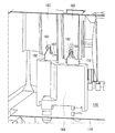
図1は、本発明にかかる車両安全装置制御ユニットの実施形態であるECU(Electronic Control Unit)114の車両101における配置を例示する図である。図1に例示するように、車両101は、安全装置として、エアバッグ100およびシートベルトプリテンショナ(以下、プリテンショナ102A・102B)を備えている。
FIG. 1 is a diagram exemplifying an arrangement in a
エアバッグ100は、ステアリングホイール104に設置されたフロントエアバッグ106、前部左座席に設けられた助手席エアバッグ107、および車室側部に設置されたカーテンエアバッグ108A・108Bを含んでいる。エアバッグ100およびプリテンショナ102A・102Bは、ECU114によって制御される。より具体的には、ECU114に搭載された加速度センサ150や、特に図示していないが、ヨーレートセンサ、ロールオーバセンサなどによる衝撃の検知に起因して作動する。特に、フロントエアバッグ106は多段階制御が可能になっていて、車両101に生じた加速度の度合いすなわち衝撃の度合いに応じて膨張展開の度合いを制御することができる。
The
図2は図1のECU114の組立図である。ECU114は、回路基板116と、回路基板116の表面118(図2では基板116の下側)を被覆する樹脂製の筐体120と、回路基板116の裏面122に固定される金属製のカバー124とを備える。筐体120の回路基板116側は開口している。カバー124、回路基板116および筐体120は、固定具としてのネジ130A、130B、130C、130Dによって固定される。これにより、回路基板116の周縁が筐体120の周縁部の側壁132、134、136に固定される。
FIG. 2 is an assembly diagram of the
図3は図2のECU114の完成図である。図3は図2のECU114を上下逆にした状態を例示している。図3では、筐体120に被覆された回路基板116の表面118は見えていず、回路基板116に設けられたコネクタ138だけが筐体120の端部から露出している。カバー124もほとんど見えていず、カバー124の両側に設けられたフランジ140、142だけが露出している。ECU114はフランジ140、142に設けられた孔144、146、148を介してネジ等(図示しない)によって車体に締結される。
FIG. 3 is a completed view of the
図4は図2の回路基板116および筐体120の斜視図である。図4では、図示の便宜上、回路基板116を図2に例示したのと上下逆にし、表面118が上を向いた状態を例示している。図4に例示するように、ECU114は、回路基板116の表面118に搭載された加速度センサ150を備える。なお加速度センサ150は回路基板116の裏面122に搭載してもよい。
FIG. 4 is a perspective view of the
図5は図3のA−A断面を例示する斜視図である。ECU114は様々な電子部品を備えているが、本願の各図面では本発明に直接関係のある電子部品だけを例示し、その他のものは図示省略している。ECU114は第1の電子部品としてドミノ154を備えている。ドミノ154は、第2の電子部品として筐体120の天面152に配置されたコンデンサ164を回路基板116と電気的に接続させる端子の一種である。ドミノ154は、図4に例示したように回路基板116の表面118に搭載されている。そしてドミノ154は、図5に例示するように、ECU114が組み立てられた状態において、筐体120の天面152から突出する保持部163、165まで延び、天面152に保持されている。
FIG. 5 is a perspective view illustrating an AA cross section of FIG. 3. The
より詳細に説明すれば、ドミノ154の上端には2つの二股の端子156、158が形成されていて、ドミノ154のうち、これら端子156、158の先端が筐体120の天面152に最も近い。一方、筐体120の天面152には、リード線160、162を有するコンデンサ164が取り付けられている。図5に例示するように、ドミノ154の上端の端子156、158は、コンデンサ164のリード線160、162を挟むように電気的に接続し、天面152から突出する保持部163、165に挿入される。これにより、コンデンサ164のリード線160、162が筐体120に保持されている。なお図5では端子156、158および保持部163、165は一部遮られて見えていない。
More specifically, two forked
図6は図5の部分拡大図であり、ドミノ154が筐体120に保持されている様子を例示する図である。ドミノ154を介した回路基板116を筐体120に保持する手順は以下の通りである。まずコンデンサ164を筐体120に組み込んだ後、ドミノ154を搭載した回路基板116を筐体120に挿入する。その過程でドミノ154の上端の端子156、158をコンデンサ164のリード線160、162に噛みこませ、さらにドミノ154を筐体120の天面150に向かって押し込む。これによって、コンデンサ164のリード線160、162を筐体120の保持部163、165が形成しているスリット167、169の最奥まで押し付ける。その結果、ECU114の上下方向に、筐体120・コンデンサ164のリード線160、162・ドミノ154・回路基板116が相互に押し合う構造になっている。これによって、ドミノ154を介して回路基板116が筐体120に保持される。
FIG. 6 is a partially enlarged view of FIG. 5, illustrating a state in which the
なおドミノ154およびその二股の端子156、158の形状は一例にすぎず、筐体120天面152側に保持されるものであれば、いかなる形状を有していてもよい。
Note that the shapes of the
(第1の実施形態)
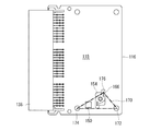
図7は図4の回路基板116の拡大図であり、本発明の第1の実施形態を例示する図である。図7に例示するように、加速度センサ150は、図4および図5に例示した筐体120の天面152の保持部163、165にドミノ154が保持された位置(本実施形態では端子156の先端)を頂点166とする三角錐170の内部空間に配置されている。この「配置されている」とは、三角錐170の内部空間に加速度センサ150の全体あるいは大部分が包含されていることが望ましいが、加速度センサ150の一部が三角錐170の内部空間に包含されている状態も含む。(First embodiment)
FIG. 7 is an enlarged view of the
三角錐170は、三角錐170の頂点166に最も近い2つのネジ130A、130B(図7では図示省略)の位置に角部172、174を形成する三角形を底面とする三角錐である。三角錐170の内部空間は、回路基板116と筐体120との間に追加された保持点(端子156の先端)すなわち三角錐170の頂点166の近傍に形成されることが望ましい。また、本実施形態では、2つの端子156、158のうち、2つのネジ130A、130Bからより遠い端子156の先端を頂点166とする三角錐170を想定している。かかる三角錐170は、2つのネジ130A、130Bからより近い端子158による制振効果も見込め、内部空間も広くなる。ただし、例えば端子158の先端を頂点とする三角錐としてもよい。
The
図8は図7の回路基板116の平面図である。三角錐170の底面である三角形は、頂点166から回路基板116に向かう垂線180(図7)の、回路基板116の表面118との交点を角部176としている。したがって図8に例示するように回路基板116を真上から見ると、三角錐170の頂点166と底面である三角形の角部176とは、重なって見え、このとき角部176と角部172、174とで形成される三角形が、三角錐170の底面となる。
FIG. 8 is a plan view of the
以上のように、本実施形態によれば、回路基板116は、図2や図4に例示したようにネジ130A、130B、130C、130Dによって回路基板116の表面118という平面上で筐体120に固定されるだけではない。すなわち図5に例示したように、回路基板116は、ドミノ154を介してさらに、筐体120の天面152方向の立体的な位置という、回路基板116の表面118から上方に離れた位置(図7の三角錐170の頂点166等)においても筐体120に保持される。かかる保持点の追加によって回路基板116の筐体120に対する固定は立体的に構築されることとなる。
As described above, according to the present embodiment, the
とりわけ、三角錐170の内部空間は、回路基板116と筐体120との間に立体的に点在する保持点(頂点166、角部172、174)で囲まれているため、堅固な構造を有する。保持点には制振効果が見込まれ、また、かかる三角錐170の内部空間に加速度センサ150が配置されているため、加速度センサ150は車両の振動による悪影響を受けにくく、安定した出力が可能となる。
In particular, the internal space of the
なお、筐体120の天面152に設けられた保持部163、165とドミノ154とは、必ずしも完全に保持(固定)されていなくてもよい。それらが相対的にわずかに動くことができるような保持であっても、逆に、そのわずかな動きによって余分な振動に対する制振効果が見込めるからである。
Note that the holding
また本実施形態によれば、振動吸収材などの部材を追加することなく加速度センサ150の出力を安定させることができるため、経済的にも有利である。
Further, according to the present embodiment, the output of the
さらに、三角錐170は、ネジ130A、130Bの位置を底面(三角形)の角部とすることで堅固な構造となっているが、底面の残りの1つの角部176も、回路基板116の表面118における、三角錐170の頂点166から最も近い点である。したがって、三角錐170の内部空間はその頂点166の近傍に形成されている。
Further, the
(第2の実施形態)
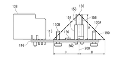
図9は図4の回路基板116の側面図であり、本発明の第2の実施形態を例示する図である。図9に例示するように、加速度センサ150は、図4および図5に例示した筐体120の天面152の、ドミノ154が保持された位置(本実施形態では端子156・158の先端のちょうど中間)を頂点186とする円錐190の内部空間に配置されている。この「配置されている」とは、円錐190の内部空間に加速度センサ150の全体あるいは大部分が包含されていることが望ましいが、加速度センサ150の一部が円錐190の内部空間に包含されている状態も含む。(Second Embodiment)
FIG. 9 is a side view of the
図10は図9の回路基板116の平面図である。上記の円錐190は、円錐190の頂点186に最も近い2つのネジ130A、130Bを内包する円を底面とする円錐である。円錐190の内部空間は、回路基板116と筐体120との間に立体的に追加された保持点(端子156・158の先端のちょうど中間)すなわち円錐190の頂点186の近傍に形成されることが望ましい。また、本実施形態では端子156・158の先端のちょうど中間を頂点186とする円錐190を想定しているが、例えば端子156または158の先端を頂点とする円錐としてもよい。
FIG. 10 is a plan view of the
図9に例示するように、円錐190の底面である円は、頂点186から回路基板116に向かう垂線200の、回路基板116の表面118との交点を中心202とし、頂点186から交点までの距離Hに等しい半径Hを有する。したがって図10に例示するように回路基板116を真上から見ると、円錐190の頂点186と底面である円の中心202とは、重なって見える。
As illustrated in FIG. 9, the circle which is the bottom surface of the
以上のように、本実施形態によれば、回路基板116は、図2や図4に例示したようにネジ130A、130B、130C、130Dによって回路基板116の表面118という平面上で筐体120に固定されるだけではない。すなわち図5に例示したように、回路基板116は、ドミノ154を介してさらに、筐体120の天面152という回路基板116の表面118から上方に離れた位置(図7の三角錐170の頂点166等)においても筐体120に保持される。かかる保持点の追加によって回路基板116の筐体120に対する固定は立体的に構築されることとなる。
As described above, according to the present embodiment, the
とりわけ、円錐190の内部空間は、回路基板116と筐体120との間に立体的に点在する保持点(頂点186、ネジ130A、130B)で囲まれているため、堅固な構造を有する。保持点には制振効果が見込まれ、また、かかる円錐190の内部空間に加速度センサ150が配置されているため、加速度センサ150は車両の振動による悪影響を受けにくく、安定した出力が可能となる。
In particular, the internal space of the
また本実施形態によれば、振動吸収材などの部材を追加することなく加速度センサ150の出力を安定させることができるため、経済的にも有利である。
Further, according to the present embodiment, the output of the
さらに、円錐190は、その底面がネジ130A、130Bを内包することで堅固な構造となっているが、底面の中心202も、回路基板116の表面118における、円錐190の頂点186から最も近い点である。そして底面である円の半径は、円錐190の高さHに等しい。したがって、円錐190の内部空間はその頂点186の近傍に形成されている。
Further, the
(ドミノ)
第1および第2の実施形態によれば、ドミノ154は、回路基板116のスペースが足りないなど、何らかの事情で筐体120の天面152に取り付けられたコンデンサ164を回路基板116に電気的に接続させる役割を果たす。言い換えれば、回路を立体的に構成したときに回路基板116と筐体120との間を橋渡しするドミノ154を利用して、その近傍に加速度センサ150を配置することにより、加速度センサ150の出力を安定させることができる。(Domino)
According to the first and second embodiments, the
(周波数応答シミュレーション解析)
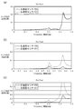
図11は図4の回路基板116に別の加速度センサ151を追加したECU214の平面図である。図11(a)は筐体120が回路基板116の表面118を被覆した状態であり、図11(b)は回路基板116から筐体120を除去した状態である。図11(b)に例示するように、ECU214には、加速度センサ150だけでなく、別の加速度センサ151が搭載されている。加速度センサ151は、加速度センサ150と異なり、第1および第2の実施形態でそれぞれ例示した三角錐170または円錐190の内部空間には配置されていない。(Frequency response simulation analysis)
FIG. 11 is a plan view of the
図12ないし図14は、図11の2つの加速度センサの周波数応答シミュレーション解析結果である。図12はECU214へのX軸方向の入力に対する加速度センサ150、151それぞれの搭載位置のX/Y/Z軸方向の揺れを出力として示すグラフである。なおZ軸方向は、図11の紙面に直交する方向である。図13はECU214へのY軸方向の入力に対する加速度センサ150、151それぞれの搭載位置のX/Y/Z軸方向の揺れを出力として示すグラフである。図14はECU214へのZ軸方向の入力に対する加速度センサ150、151それぞれの搭載位置のX/Y/Z軸方向の揺れを出力として示すグラフである。図12ないし図14において、縦軸は加速度出力、横軸は周波数を示している。
12 to 14 show the frequency response simulation analysis results of the two acceleration sensors shown in FIG. FIG. 12 is a graph showing, as an output, fluctuations in the X / Y / Z-axis direction of the mounting positions of the
図12(a)、図13(a)および図14(a)にそれぞれ例示する通り、X/Y/Z軸方向の入力に対するX軸方向の揺れは、加速度センサ150、151のいずれも、ほとんど差がない。一方、図12(b)(c)、図13(b)(c)および図14(b)(c)にそれぞれ例示する通り、X/Y/Z軸方向の入力に対するY/Z軸方向の揺れは、ほとんどの周波数領域において、加速度センサ150のほうが加速度センサ151より低い値を示している。
As illustrated in FIG. 12A, FIG. 13A, and FIG. 14A, respectively, the fluctuation in the X-axis direction with respect to the input in the X / Y / Z-axis direction is almost the same in both the
以上の周波数応答解析の結果より、本発明の第1および第2の実施形態で例示した三角錐170または円錐190の内部空間に配置された加速度センサ150の出力のほうが、内部空間の外に配置された加速度センサ151の出力よりも、振動による影響を受け難いことがわかる。
From the result of the frequency response analysis described above, the output of the
以上、添付図面を参照しながら本発明の好適な実施形態について説明したが、本発明は係る例に限定されないことは言うまでもない。当業者であれば、特許請求の範囲に記載された範疇内において、各種の変更例または修正例に想到し得ることは明らかであり、それらについても当然に本発明の技術的範囲に属するものと了解される。 As mentioned above, although preferred embodiment of this invention was described referring an accompanying drawing, it cannot be overemphasized that this invention is not limited to the example which concerns. It will be apparent to those skilled in the art that various changes and modifications can be made within the scope of the claims, and these are naturally within the technical scope of the present invention. Understood.
本発明は、車両衝突時に車両に生じた加速度を検出する加速度センサ等を搭載し、車両用安全装置を制御する車両安全装置制御ユニットに利用することができる。 INDUSTRIAL APPLICABILITY The present invention can be used in a vehicle safety device control unit that includes an acceleration sensor that detects acceleration generated in a vehicle at the time of a vehicle collision and controls a vehicle safety device.
Claims (8)
回路基板と、
前記回路基板の表面または裏面に搭載されたセンサと、
前記回路基板を被覆する筐体と、
前記回路基板の周縁を前記筐体の周縁部に固定する複数の固定具と、
前記回路基板の表面に搭載され前記筐体の天面方向に延び該天面から突出する保持部に保持される第1の電子部品とを備え、
第1の電子部品の前記筐体の天面に最も近い上端部を頂点とする三角錐であって、該頂点から前記回路基板に向かう垂線の該回路基板の表面との交点の角部と、前記複数の固定具のうち2つの固定具の位置の2つの角部から構成される三角形を底面とする三角錐の内部空間に前記センサが配置されていることを特徴とする車両安全装置制御ユニット。In a vehicle safety device control unit for controlling a vehicle safety device,
A circuit board;
A sensor mounted on the front or back surface of the circuit board;
A housing covering the circuit board;
A plurality of fixtures for fixing the periphery of the circuit board to the periphery of the housing;
A first electronic component mounted on the surface of the circuit board and held in a holding portion that extends in the top surface direction of the housing and protrudes from the top surface;
A triangular pyramid having an upper end closest to the top surface of the housing of the first electronic component as a vertex, and a corner of an intersection of a perpendicular line from the vertex to the surface of the circuit board; The vehicle safety device control unit, characterized in that the sensor is arranged in an internal space of a triangular pyramid having a triangle formed from two corners at positions of two fixtures among the plurality of fixtures. .
回路基板と、
前記回路基板の表面または裏面に搭載されたセンサと、
前記回路基板を被覆する筐体と、
前記回路基板の周縁を前記筐体の周縁部に固定する複数の固定具と、
前記回路基板の表面に搭載され前記筐体の天面方向に延び該天面から突出する保持部に保持される第1の電子部品とを備え、
第1の電子部品が保持された位置を頂点とする円錐であって、前記複数の固定具のうち第1の電子部品に近い少なくとも2つの固定具を内包する円を底面とする円錐の内部空間に前記センサが配置されていることを特徴とする車両安全装置制御ユニット。In a vehicle safety device control unit for controlling a vehicle safety device,
A circuit board;
A sensor mounted on the front or back surface of the circuit board;
A housing covering the circuit board;
A plurality of fixtures for fixing the periphery of the circuit board to the periphery of the housing;
A first electronic component mounted on the surface of the circuit board and held in a holding portion that extends in the top surface direction of the housing and protrudes from the top surface;
An internal space of a cone whose top is a cone having a position where the first electronic component is held, the circle containing at least two fixtures close to the first electronic component among the plurality of fixtures. The vehicle safety device control unit is characterized in that the sensor is disposed in the vehicle.
回路基板と、
前記回路基板の表面または裏面に搭載されたセンサと、
前記回路基板を被覆する筐体と、
前記回路基板の周縁を前記筐体の周縁部に固定する複数の固定具と、
前記回路基板の表面に搭載され前記筐体の天面方向に延び該天面から突出する保持部に保持される第1の電子部品とを備え、
第1の電子部品が保持された位置を頂点とする円錐であって、前記頂点から前記回路基板に向かう垂線の該回路基板の表面との交点を中心とし前記頂点から交点までの距離に等しい半径を有する円を底面とする円錐の内部空間に前記センサが配置されていることを特徴とする車両安全装置制御ユニット。In a vehicle safety device control unit for controlling a vehicle safety device,
A circuit board;
A sensor mounted on the front or back surface of the circuit board;
A housing covering the circuit board;
A plurality of fixtures for fixing the periphery of the circuit board to the periphery of the housing;
A first electronic component mounted on the surface of the circuit board and held in a holding portion that extends in the top surface direction of the housing and protrudes from the top surface;
A cone having a vertex at a position where the first electronic component is held, and a radius equal to a distance from the vertex to the intersection centered on an intersection with a surface of the circuit board of a perpendicular line from the vertex to the circuit board A vehicle safety device control unit, wherein the sensor is disposed in an inner space of a cone having a circle having a bottom surface.
第1の電子部品の上端には、第2の電子部品のリード線に電気的に接続し、前記筐体の天面から突出する保持部に保持される端子が形成されていることを特徴とする請求項1から4のいずれか1項に記載の車両安全装置制御ユニット。A second electronic component attached to the top surface of the housing and having a lead wire;
The upper end of the first electronic component is formed with a terminal that is electrically connected to the lead wire of the second electronic component and is held by a holding portion protruding from the top surface of the housing. The vehicle safety device control unit according to any one of claims 1 to 4.
Applications Claiming Priority (3)
| Application Number | Priority Date | Filing Date | Title |
|---|---|---|---|
| JP2013227778 | 2013-10-31 | ||
| JP2013227778 | 2013-10-31 | ||
| PCT/JP2014/073137 WO2015064203A1 (en) | 2013-10-31 | 2014-09-03 | Vehicle safety device control unit |
Publications (2)
| Publication Number | Publication Date |
|---|---|
| JP6000472B2 true JP6000472B2 (en) | 2016-09-28 |
| JPWO2015064203A1 JPWO2015064203A1 (en) | 2017-03-09 |
Family
ID=53003816
Family Applications (1)
| Application Number | Title | Priority Date | Filing Date |
|---|---|---|---|
| JP2015544848A Expired - Fee Related JP6000472B2 (en) | 2013-10-31 | 2014-09-03 | Vehicle safety device control unit |
Country Status (3)
| Country | Link |
|---|---|
| JP (1) | JP6000472B2 (en) |
| DE (1) | DE112014004998T5 (en) |
| WO (1) | WO2015064203A1 (en) |
Families Citing this family (3)
| Publication number | Priority date | Publication date | Assignee | Title |
|---|---|---|---|---|
| JP2017132283A (en) * | 2016-01-25 | 2017-08-03 | 株式会社デンソー | Control device for occupant protection system |
| CN114867987B (en) * | 2020-02-28 | 2025-06-13 | Jvc建伍株式会社 | Navigation device and method for manufacturing navigation device |
| CZ310044B6 (en) * | 2022-01-06 | 2024-06-12 | Výzkumný a zkušební letecký ústav, a.s. | A chassis of a sensor of a capacitive micro accelerometer |
Family Cites Families (4)
| Publication number | Priority date | Publication date | Assignee | Title |
|---|---|---|---|---|
| DE102006036792A1 (en) * | 2006-08-07 | 2008-02-14 | Trw Automotive Gmbh | Method for producing a sensor and sensor |
| JP5378864B2 (en) * | 2009-04-03 | 2013-12-25 | 富士通テン株式会社 | Housing structure for automotive electronic devices |
| JP5318720B2 (en) * | 2009-09-30 | 2013-10-16 | 富士通テン株式会社 | Electronic control unit |
| JP2012177652A (en) * | 2011-02-28 | 2012-09-13 | Keihin Corp | Electronic control device |
-
2014
- 2014-09-03 DE DE112014004998.0T patent/DE112014004998T5/en active Pending
- 2014-09-03 WO PCT/JP2014/073137 patent/WO2015064203A1/en not_active Ceased
- 2014-09-03 JP JP2015544848A patent/JP6000472B2/en not_active Expired - Fee Related
Also Published As
| Publication number | Publication date |
|---|---|
| JPWO2015064203A1 (en) | 2017-03-09 |
| WO2015064203A1 (en) | 2015-05-07 |
| DE112014004998T5 (en) | 2016-07-14 |
Similar Documents
| Publication | Publication Date | Title |
|---|---|---|
| JP5184286B2 (en) | Housing fixing structure | |
| JP5318720B2 (en) | Electronic control unit | |
| JP5378864B2 (en) | Housing structure for automotive electronic devices | |
| US20120292469A1 (en) | Fastening Assembly for a Sensor Assembly and Sensor Assembly | |
| CN102356012B (en) | Occupant restraint device control device | |
| US5706181A (en) | Sensor unit for controlling an occupant protection system of a motor vehicle | |
| JP6000472B2 (en) | Vehicle safety device control unit | |
| JP6136402B2 (en) | Sensor unit, electronic device, and moving object | |
| JP2018199431A (en) | Vehicle body front part structure | |
| JP2010132202A (en) | Sensor device and vehicle with the same | |
| WO2021132594A1 (en) | Electronic device | |
| JP2012177652A (en) | Electronic control device | |
| JP7698974B2 (en) | Control device | |
| JP2018072170A (en) | Inertial force sensor device | |
| JP2017083361A (en) | Inertial force sensor | |
| CN111316082B (en) | Pressure sensor and mobile device with pressure sensor | |
| JP2018133373A (en) | Electronic equipment | |
| KR101609341B1 (en) | 3-dimensional vibration platform structure for micromachined systems | |
| JP2015210161A (en) | Inertia force sensor device | |
| JP2007322146A (en) | Sensor module | |
| US20220268800A1 (en) | Hybrid sensor assembly for use with active noise cancellation | |
| JP5270649B2 (en) | Control device for occupant restraint system | |
| JP5966864B2 (en) | Electronic equipment | |
| US12492903B2 (en) | Navigation device and method of manufacturing navigation device | |
| JP6068153B2 (en) | Harness protector |
Legal Events
| Date | Code | Title | Description |
|---|---|---|---|
| TRDD | Decision of grant or rejection written | ||
| A01 | Written decision to grant a patent or to grant a registration (utility model) |
Free format text: JAPANESE INTERMEDIATE CODE: A01 Effective date: 20160816 |
|
| A61 | First payment of annual fees (during grant procedure) |
Free format text: JAPANESE INTERMEDIATE CODE: A61 Effective date: 20160830 |
|
| R150 | Certificate of patent or registration of utility model |
Ref document number: 6000472 Country of ref document: JP Free format text: JAPANESE INTERMEDIATE CODE: R150 |
|
| S111 | Request for change of ownership or part of ownership |
Free format text: JAPANESE INTERMEDIATE CODE: R313113 |
|
| R350 | Written notification of registration of transfer |
Free format text: JAPANESE INTERMEDIATE CODE: R350 |
|
| R250 | Receipt of annual fees |
Free format text: JAPANESE INTERMEDIATE CODE: R250 |
|
| LAPS | Cancellation because of no payment of annual fees |