JP6136402B2 - Sensor unit, electronic device, and moving object - Google Patents
Sensor unit, electronic device, and moving object Download PDFInfo
- Publication number
- JP6136402B2 JP6136402B2 JP2013053258A JP2013053258A JP6136402B2 JP 6136402 B2 JP6136402 B2 JP 6136402B2 JP 2013053258 A JP2013053258 A JP 2013053258A JP 2013053258 A JP2013053258 A JP 2013053258A JP 6136402 B2 JP6136402 B2 JP 6136402B2
- Authority
- JP
- Japan
- Prior art keywords
- wall portion
- sensor module
- wall
- sensor
- detection axis
- Prior art date
- Legal status (The legal status is an assumption and is not a legal conclusion. Google has not performed a legal analysis and makes no representation as to the accuracy of the status listed.)
- Active
Links
Images


Classifications
-
- G—PHYSICS
- G01—MEASURING; TESTING
- G01D—MEASURING NOT SPECIALLY ADAPTED FOR A SPECIFIC VARIABLE; ARRANGEMENTS FOR MEASURING TWO OR MORE VARIABLES NOT COVERED IN A SINGLE OTHER SUBCLASS; TARIFF METERING APPARATUS; MEASURING OR TESTING NOT OTHERWISE PROVIDED FOR
- G01D11/00—Component parts of measuring arrangements not specially adapted for a specific variable
- G01D11/24—Housings ; Casings for instruments
- G01D11/245—Housings for sensors
-
- G—PHYSICS
- G01—MEASURING; TESTING
- G01C—MEASURING DISTANCES, LEVELS OR BEARINGS; SURVEYING; NAVIGATION; GYROSCOPIC INSTRUMENTS; PHOTOGRAMMETRY OR VIDEOGRAMMETRY
- G01C19/00—Gyroscopes; Turn-sensitive devices using vibrating masses; Turn-sensitive devices without moving masses; Measuring angular rate using gyroscopic effects
- G01C19/56—Turn-sensitive devices using vibrating masses, e.g. vibratory angular rate sensors based on Coriolis forces
- G01C19/5783—Mountings or housings not specific to any of the devices covered by groups G01C19/5607 - G01C19/5719
-
- G—PHYSICS
- G01—MEASURING; TESTING
- G01P—MEASURING LINEAR OR ANGULAR SPEED, ACCELERATION, DECELERATION, OR SHOCK; INDICATING PRESENCE, ABSENCE, OR DIRECTION, OF MOVEMENT
- G01P1/00—Details of instruments
- G01P1/02—Housings
- G01P1/023—Housings for acceleration measuring devices
Landscapes
- Physics & Mathematics (AREA)
- General Physics & Mathematics (AREA)
- Engineering & Computer Science (AREA)
- Radar, Positioning & Navigation (AREA)
- Remote Sensing (AREA)
- Gyroscopes (AREA)
Description
本発明は、センサーユニット、およびそのセンサーユニットを用いた電子機器や移動体等に関する。 The present invention relates to a sensor unit, an electronic device using the sensor unit, a moving body, and the like.
例えば特許文献1には、3軸の各速度を検出する3軸ジャイロセンサーを有するモジュールを軸合わせして収容するセンサーモジュールが開示されている。このセンサーモジュールは、小型化を可能としながら、モジュールの位置を簡単かつ正確に位置決めで切る点で優れている。 For example, Patent Document 1 discloses a sensor module that accommodates a module having a three-axis gyro sensor that detects each of three-axis speeds. This sensor module is excellent in that the position of the module can be easily and accurately cut while being miniaturized.
この種のセンサーモジュールをユーザーが電子機器または移動体等の被検出体に取り付けるには、センサーモジュールに耐環境性を確保しなければならないことがある。耐環境性として、耐水性、耐圧性、または耐衝撃性等を挙げることができる。 In order for a user to attach this type of sensor module to a detected object such as an electronic device or a moving object, it may be necessary to ensure environmental resistance of the sensor module. Examples of environmental resistance include water resistance, pressure resistance, and impact resistance.
そのため、被検出体側でセンサーモジュールの耐環境性を確保するよりも、センサーモジュールを耐環境性のある外装体に収容したセンサーユニット化した方が、ユーザーには好ましい。 For this reason, it is preferable for the user to use a sensor unit in which the sensor module is housed in an environment-resistant exterior body, rather than ensuring the environment resistance of the sensor module on the detected object side.
しかし、特許文献1に示すセンサーモジュールや、そのセンサーモジュールを外装体に収容したセンサーユニットを被検出体に取り付けるには、センサーモジュールの検出軸を被検出体の特定方向に一致させる必要がある。 However, in order to attach the sensor module shown in Patent Document 1 or the sensor unit in which the sensor module is housed in the exterior body to the detected body, it is necessary to match the detection axis of the sensor module with the specific direction of the detected body.
本発明の幾つかの態様は、センサーモジュールに耐環境性を確保する外装体を電子機器または移動体等の被検出体に取り付ける際に、被検出体に対するセンサーモジュールの検出軸の相対位置を一義的に定めることができるセンサーユニット、電子機器、および移動体を提供することを目的とする。 Some aspects of the present invention define a relative position of a detection axis of a sensor module with respect to a detected object when an exterior body that secures environmental resistance is attached to the detected object such as an electronic device or a moving object. It is an object of the present invention to provide a sensor unit, an electronic device, and a moving body that can be determined in a specific manner.
(1)本発明の一態様は、
センサーモジュールと、
前記センサーモジュールと電気的に接続されたコネクターと、
前記センサーモジュールを包囲する複数の壁部を有し、前記コネクターの一部を外部に露出させる開口が前記複数の壁部の一つである第1壁部に設けられた外装体と、
を有し、
前記センサーモジュールは、第1面と第2面とを有し、
前記外装体は、
前記センサーモジュールの前記第1面を位置決めする第1基準内面と、
前記第1基準内面と平行であって、前記第1壁部とは異なる第2壁部の外面に設けられる第1基準外面と、
前記センサーモジュールの前記第2面を位置決めする第2基準内面と、
前記第2基準内面と平行であって、前記第1壁部及び前記第2壁部とは異なる第3壁部の外面に設けられる第2基準外面と、
を有するセンサーユニットに関する。
(1) One aspect of the present invention is
A sensor module;
A connector electrically connected to the sensor module;
A plurality of wall portions surrounding the sensor module, and an exterior body provided in a first wall portion in which an opening exposing a part of the connector to the outside is one of the plurality of wall portions;
Have
The sensor module has a first surface and a second surface;
The exterior body is
A first reference inner surface for positioning the first surface of the sensor module;
A first reference outer surface that is parallel to the first reference inner surface and provided on an outer surface of a second wall portion different from the first wall portion;
A second reference inner surface for positioning the second surface of the sensor module;
A second reference outer surface that is parallel to the second reference inner surface and provided on an outer surface of a third wall portion different from the first wall portion and the second wall portion;
It relates to a sensor unit having
本発明の一態様によれば、センサーモジュールの第1面及び第2面が、外装体の第1基準内面及び第2基準内面に位置決めされるので、外装体に対するセンサーモジュールの相対位置が一義的に定まる。外装体は、第1基準内面及び第2基準内面にそれぞれ平行な第1基準外面及び第2基準外面を有する。このセンサーユニットが取り付けられる被検出体に対して第1基準外面及び第2基準外面が位置決めされると、被検出体に対するセンサーユニットの相対位置が一義的に定まる。よって、被検出体に対するセンサーモジュールの相対位置も一義的に定まる。それにより、センサーモジュールの第1面及び第2面と検出軸との関係が固定であることから、被検出体に対するセンサーモジュールの検出軸の相対位置が一義的に定まる。 According to one aspect of the present invention, the first surface and the second surface of the sensor module are positioned on the first reference inner surface and the second reference inner surface of the exterior body, so that the relative position of the sensor module with respect to the exterior body is unambiguous. Determined. The exterior body has a first reference outer surface and a second reference outer surface that are parallel to the first reference inner surface and the second reference inner surface, respectively. When the first reference outer surface and the second reference outer surface are positioned with respect to the detected object to which the sensor unit is attached, the relative position of the sensor unit with respect to the detected object is uniquely determined. Therefore, the relative position of the sensor module with respect to the detection target is also uniquely determined. Thereby, since the relationship between the first surface and the second surface of the sensor module and the detection axis is fixed, the relative position of the detection axis of the sensor module with respect to the detection target is uniquely determined.
(2)本発明の一態様では、前記センサーモジュールは、第1検出軸に沿った加速度及び前記第1検出軸廻りの角速度の少なくとも一方を検出する第1センサー素子と、前記第1検出軸と交差する第2検出軸に沿った加速度及び前記第2検出軸廻りの角速度の少なくとも一方を検出する第2センサー素子と、を含み、前記第1基準内面は、前記第1検出軸及び前記第2検出軸で規定される平面と平行であり、前記第2基準内面は、前記第1検出軸と平行とすることができる。それにより、被検出体に対するセンサーの第1,第2検出軸の相対位置が一義的に定まる。 (2) In an aspect of the present invention, the sensor module includes a first sensor element that detects at least one of acceleration along a first detection axis and an angular velocity around the first detection axis, and the first detection axis. A second sensor element that detects at least one of acceleration along the intersecting second detection axis and angular velocity around the second detection axis, wherein the first reference inner surface includes the first detection axis and the second detection axis. The second reference inner surface may be parallel to the first detection axis and parallel to a plane defined by the detection axis. Thereby, the relative positions of the first and second detection axes of the sensor with respect to the detected object are uniquely determined.
(3)本発明の一態様では、前記外装体は、前記底壁と平行する段差面をさらに有し、前記第2基準内面は、前記底壁と前記段差面とを結ぶ面に形成することができる。こうして、第2基準内面を外装体のいずれかの壁部自体の内壁面に形成するよりも、第2基準内面の幅や高さを位置決めに必要な範囲で小さくすることで、小面積な面に形成できる。それにより、底壁に対して第2基準内面を加工して垂直度を出す際の加工面積を少なくできる。 (3) In one aspect of the present invention, the exterior body further includes a step surface parallel to the bottom wall, and the second reference inner surface is formed on a surface connecting the bottom wall and the step surface. Can do. In this way, a surface with a small area can be obtained by reducing the width and height of the second reference inner surface within the range necessary for positioning rather than forming the second reference inner surface on the inner wall surface of any wall part itself of the exterior body. Can be formed. Thereby, the processing area when processing the second reference inner surface with respect to the bottom wall to obtain the perpendicularity can be reduced.
(4)本発明の一態様では、前記外装体は、筐体と蓋体とを含み、前記筐体は、前記第2壁部で設けられる底壁と、前記底壁より立ち上がる前記第1壁部及び前記第3壁部を含み、前記底壁に前記第1基準内面及び前記第1基準外面を形成することができる。こうすると、センサーモジュールの第1検出軸及び記第2検出軸で規定される平面を、外装体の底壁と平行にすることができる。外装体の第1基準外面を被検出体に位置決めすれば、センサーモジュールの第1検出軸及び記第2検出軸で規定される平面と被検出体との相対位置を一義的に定めることができる。 (4) In one aspect of the present invention, the exterior body includes a housing and a lid, and the housing includes a bottom wall provided by the second wall portion, and the first wall rising from the bottom wall. The first reference inner surface and the first reference outer surface may be formed on the bottom wall. In this way, the plane defined by the first detection axis and the second detection axis of the sensor module can be made parallel to the bottom wall of the exterior body. If the first reference outer surface of the exterior body is positioned on the detected body, the relative position between the detected surface and the plane defined by the first detection axis and the second detection axis of the sensor module can be uniquely determined. .
(5)本発明の一態様では、前記第1壁部と前記第3壁部とを対向させることができる。第1壁部と第3壁部とが交差する関係であると、コネクターの中心軸(または外装体の中心軸)よりも一方に偏らせてセンサーモジュールを配置することになり、センサーユニットの重量バランスが悪化する。本発明の一態様では、コネクターの中心軸(または外装体の中心軸)とセンサーモジュールの中心軸とを一致させ易く、重量バランスが良いセンサーユニットを構成できる。 (5) In 1 aspect of this invention, the said 1st wall part and the said 3rd wall part can be made to oppose. When the first wall portion and the third wall portion intersect, the sensor module is arranged so as to be biased to one side with respect to the central axis of the connector (or the central axis of the exterior body), and the weight of the sensor unit. The balance gets worse. In one embodiment of the present invention, a sensor unit having a good weight balance can be configured, in which the central axis of the connector (or the central axis of the exterior body) and the central axis of the sensor module are easily aligned.
(6)本発明の一態様では、前記センサーモジュールの前記第2面は、前記外装体の前記第3壁部と対向する面に形成することができる。こうすると、センサーモジュールの第2面を位置決めする第2基準内壁面と、外装体の第3壁部に設けられる第2基準外面とを近くに配置でき、第2基準内面と第2基準外面との間の寸法精度(平行度)が出し易くなる。その上、コネクターに沿った方向(またはコネクターの突出方向)でのセンサーユニットの長さを短縮して小型化することができる。 (6) In one aspect of the present invention, the second surface of the sensor module can be formed on a surface facing the third wall portion of the exterior body. In this way, the second reference inner wall surface for positioning the second surface of the sensor module and the second reference outer surface provided on the third wall portion of the exterior body can be arranged close to each other, and the second reference inner surface and the second reference outer surface can be arranged. Dimensional accuracy (parallelism) between the two is easily obtained. In addition, the length of the sensor unit in the direction along the connector (or the protruding direction of the connector) can be shortened to reduce the size.
(7)本発明の一態様では、前記コネクターが接続されるコネクター基板がさらに設けられ、前記コネクター基板は、前記第1壁部と前記センサーモジュールとの間にて、前記第1壁部と平行に支持することができる。上述した(5)または(6)の構造を前提とすると、第1壁部の長さはコネクター基板の長さに応じて設計しても、第1壁部と対向する第3壁部に設けられる第2基準外面の位置や、第2基準内面の位置は、第1壁部の長さに依存しない構造となる。 (7) In an aspect of the present invention, a connector board to which the connector is connected is further provided, and the connector board is parallel to the first wall part between the first wall part and the sensor module. Can be supported. Assuming the structure of (5) or (6) described above, even if the length of the first wall portion is designed according to the length of the connector board, it is provided on the third wall portion facing the first wall portion. The position of the second reference outer surface and the position of the second reference inner surface that are formed are independent of the length of the first wall portion.
(8)本発明の一態様では、前記コネクター基板と前記センサーモジュールとの間の配線を中継する中継基板を、前記第4壁部及び前記第5壁部の一方と前記センサーモジュールとの間にて、前記センサーモジュールに配置することができる。上述の(8)の構造を前提とすると、第4壁部及び前記第5壁部の一方とセンサーモジュールとの間に確保できるスペースを利用して、中継基板をセンサーモジュールに取り付けることができる。 (8) In one aspect of the present invention, a relay board for relaying the wiring between the connector board and the sensor module is provided between one of the fourth wall part and the fifth wall part and the sensor module. The sensor module can be arranged. Assuming the structure of (8) described above, the relay board can be attached to the sensor module using a space that can be secured between one of the fourth wall portion and the fifth wall portion and the sensor module.
(9)本発明の一態様では、前記外装体は、筐体と蓋体とを含み、前記蓋体が前記第1壁部で設けられ、前記筐体は、前記第2壁部で設けられる底壁と、前記底壁より立ち上がる前記第3壁部、第4壁部、第5壁部及び第6壁部とを有し、前記底壁に前記第1基準内面及び前記第1基準外面を形成することができる。それにより、上述の(4)の構造とは異なり、コネクターが蓋体にて露出するタイプのセンサーユニットを構成できるが、(4)の構造と同一の作用効果を奏することができる。 (9) In one aspect of the present invention, the exterior body includes a housing and a lid, the lid is provided by the first wall portion, and the housing is provided by the second wall portion. A bottom wall; and the third wall portion, the fourth wall portion, the fifth wall portion, and the sixth wall portion that rise from the bottom wall, and the first reference inner surface and the first reference outer surface are provided on the bottom wall. Can be formed. Thus, unlike the above-described structure (4), a sensor unit in which the connector is exposed by the lid can be configured, but the same operational effects as the structure (4) can be achieved.
(10)本発明の一態様では、前記センサーモジュールは、前記第1検出軸及び前記第2検出軸と交差する第3検出軸に沿った方向の加速度及び前記第3検出軸廻りの角速度の少なくとも一方を検出する第3センサー素子をさらに有することができる。それにより、被検出体に対する第3検出軸の相対位置も一義的に定まる。 (10) In one aspect of the invention, the sensor module includes at least acceleration in a direction along a third detection axis that intersects the first detection axis and the second detection axis, and an angular velocity around the third detection axis. A third sensor element for detecting one can be further included. Thereby, the relative position of the third detection axis with respect to the detection target is also uniquely determined.
(11)本発明の一態様では、前記第2基準内面が前記第1検出軸と平行に延びる方向の両端部に、前記第2基準内面と交差する干渉面を有することができる。こうすると、センサーモジュールを外装体に取り付ける時に、センサーモジュールの位置がずれるとセンサーモジュールが干渉面と干渉する。それにより、第2基準内面からセンサーモジュールが外れることを防止し、あるいは外れたことを認識し易くすることができる。干渉面は曲面等で形成することができる。 (11) In the aspect of the invention, the second reference inner surface may have interference surfaces intersecting the second reference inner surface at both ends in a direction extending in parallel with the first detection axis. Thus, when the sensor module is attached to the exterior body, the sensor module interferes with the interference surface if the position of the sensor module is shifted. Thereby, it is possible to prevent the sensor module from being detached from the second reference inner surface, or to easily recognize the separation. The interference surface can be formed by a curved surface or the like.
(12)本発明のさらに他の態様は、上述の(1)〜(11)のいずれかに記載のセンサーユニットを有する電子機器に関する。 (12) Still another embodiment of the present invention relates to an electronic device having the sensor unit according to any one of (1) to (11) above.
(13)本発明のさらに他の態様は、上述の(1)〜(11)のいずれかに記載のセンサーユニットを有する移動体に関する。 (13) Still another embodiment of the present invention relates to a moving body having the sensor unit according to any one of (1) to (11) above.
本発明に係る電子機器及び移動体では、センサーモジュールの検出軸を電子機器及び移動体に対して一義的に定めることができる。 In the electronic device and the moving body according to the present invention, the detection axis of the sensor module can be uniquely determined with respect to the electronic device and the moving body.
以下、本発明の好適な実施の形態について詳細に説明する。なお以下に説明する本実施形態は特許請求の範囲に記載された本発明の内容を不当に限定するものではなく、本実施形態で説明される構成の全てが本発明の解決手段として必須であるとは限らない。 Hereinafter, preferred embodiments of the present invention will be described in detail. The present embodiment described below does not unduly limit the contents of the present invention described in the claims, and all the configurations described in the present embodiment are indispensable as means for solving the present invention. Not necessarily.
1.第1実施形態
1.1.センサーユニットの概要
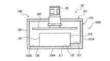
図1に示すように、本実施形態に係るセンサーユニット1Aは、例えば防水性の外装体10Aを有する。外装体10Aは金属例えばアルミニウムにて形成することができる。外装体10Aは、筐体100Aと蓋体106とを有する。センサーユニット1Aから蓋体106を取り外した図2に示すように、筐体100A内には図3に示すセンサーモジュール20とコネクター30とが配置される。筐体100Aと蓋体106とから成る外装体10Aを形成する複数の壁部のうち、コネクター30を外部に露出させるための開口110(図6参照)が形成された壁部を第1壁部101と称する。コネクター30は、筐体110に支持されるコネクター基板300に固定して支持される。コネクター30は、複数のセンサーユニットの各々を外部コントローラーとバス接続、例えばCAN(Controller Area Network)バス接続するための5ピンコネクターである。コネクター基板300には、CANのプロトコルを実行するための電子部品を搭載することができる。
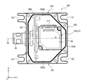
1. 1. First embodiment 1.1. Overview of Sensor Unit As shown in FIG. 1, a
筐体100Aは、図3及び図3のV−V断面図である図4に示すように、底壁(第2壁部)102と、底壁102から垂直に立ち上がる第1壁部101、第3壁部103、第4壁部104及び第5壁部105を有する。蓋体106は第6壁部である。
The housing 100A includes a bottom wall (second wall portion) 102, a
直交(交差)3軸をX,Y,Zとすると、第1壁部101と第3壁部103がY方向にて対向する。第4壁部104と第5壁部106とはX方向にて対向する。第2壁部(底壁)102と第6壁部(蓋体)106とはZ方向にて対向する。本実施形態の外装体10Aは、筐体100Aと蓋体106との間、および開口110とコネクター30との間を、例えばパッキン等で封止することで防水構造を確保している。
When the three orthogonal (crossing) axes are X, Y, and Z, the
1.2.センサーモジュール
センサーモジュール20は、図3に示すように、外装体10A内に配置される内装体200を有する。内装体200は樹脂で形成され、耐環境性を有しない。内装体200は、底体210と筐体220とを有する。底体210がZ方向にて露出する外壁面を第1面211と称し、底体210がX方向にて露出する外壁面を第2面212と称する。これら第1,第2面211,212は、センサーモジュール20を外装体100Aに取付ける時に位置決め用の基準面として機能する。
1.2. Sensor Module As shown in FIG. 3, the
センサーモジュール20は、例えば特許文献1に開示された構造を用いることができる。内装体200の内部には、四角枠状の保持部材が設けられ、その保持部材にセンサー素子を搭載した実装基板が保持される。実装基板は、リジット基板とフレキシブル基板とを連結したもので、展開状態で平面をなす。その実装基板に、少なくとも二軸(X,Y軸)と平行な第1,第2検出軸、または三軸(X,Y,Z軸)と平行な第1〜第3検出軸を有するセンサー素子が搭載される。フレキシブル基板を屈曲させて、リジット基板とフレキシブル基板とが、各検出軸と平行に維持されて支持部材に取付けられる。センサー素子は、各検出軸に沿った方向の加速度及び各検出軸廻りの各加速度の少なくとも一方を検出するものである。本実施形態では、センサーモジュール20は、3軸加速度センサーと3軸ジャイロセンサーとを含んでいる。
The
特許文献1の構造によれば、底体(保持部材)210の四隅にアライメント部が設けられている。アライメント部は、底体210に対して、X,Y,Z軸方向及び各軸廻りの方向にて支持部材を位置決めする。つまり、第1検出軸と第2検出軸とで規定される平面は、センサーモジュール20の第1面(X−Y平面)211と平行になり、第1検出軸はセンサーモジュール20の第2面と平行になり、第3検出軸は第1面211と直交(交差)するように位置決めされる。
According to the structure of Patent Document 1, alignment portions are provided at the four corners of the bottom body (holding member) 210. The alignment unit positions the support member with respect to the
センサーモジュール20は、底体210の平面視で対角線上に位置する2か所に、取り付け用の切欠き孔213,214を有する。また、センサーモジュール20の例えばY方向の側面には、中継基板215を取り付けることができる。中継基板215は、内装体200の内部のリジット基板及びフレキシブル基板と、コネクター基板300とを中継する。内装体200の内部のリジット基板及びフレキシブル基板には上述のセンサー素子が設けられる。センサー素子からのアナログ信号を増幅する増幅器、アナログ信号をデジタル信号に変換するA/D変換器、マイクロコントローラー、不揮発性メモリーまたき方位センサー(磁気センサー)等を、内装体200の内部のリジット基板及びフレキシブル基板または中継基板215に搭載することができる。中継基板215には、コネクター基板300と中継基板215とを接続する内部コネクター216を設けることができる。
The
1.3.センサーモジュールと外装体、及びセンサーユニットと被検出体との位置決め
外装体10Aの筐体100Aは、センサーモジュール20の第1面211を位置決めする第1基準内面102Bを有する。第1基準内面102Bは、底壁(第2壁部)102の内表面に形成される。外装体10Aの筐体100Aは、第1基準内面102Bと平行な第1基準外面102Aを有する。第1基準外面102Aは、底壁(第2壁部)102の外表面に形成される。
1.3. Positioning of Sensor Module and Exterior Body, and Sensor Unit and Detected Body The housing 100A of the
外装体10Aの筐体100Aは、センサーモジュール20の第2面212を位置決めする第2基準内面120を有する。ここで、筐体100Aは、底壁(第2壁部)102と平行な段差面121を有することができる。この場合、第2基準内面120は、底壁102の内面102Bと段差面121とを結ぶ面(垂直面)に形成することができる。さらに、第2基準内面120と平行な第3壁部103の外面に、第2基準外面103Aが形成される。
The
センサーモジュール20を外装体10Aの筐体100Aに取付ける際には、センサーモジュール20の第1,第2面211,212を筐体100Aの第1,第2基準内面102B,120に位置決めし、ワッシャーが挿通されたボルトを切欠き孔1213,214(図3)に挿入して、センサーモジュール20を外装体10Aの筐体100Aに取付ける。
When the
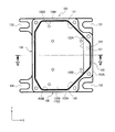
外装体10Aの筐体100Aは、図2及び図5に示すように、四隅に取付け用の切欠き孔131〜134を有する。このセンサーユニット1Aを被検出体に取付ける際には、筐体100Aの第1,第2基準外面102A,103Aを被検出体に位置決めし、ワッシャーが挿通されたボルトを切欠き孔131〜134に挿入して、センサーユニット1Aを被検出体に締結する。
As shown in FIGS. 2 and 5, the
図5にて鎖線で示すように、センサーモジュール20の第1面211及び第2面212が、外装体10Aの筐体100Aに形成された第1基準内面102B及び第2基準内面120に位置決めされる。それにより、外装体10Aに対するセンサーモジュール20の相対位置が一義的に定まる。外装体10Aは、第1基準内面102B及び第2基準内面120にそれぞれ平行な第1基準外面102A及び第2基準外面103Aを有する。このセンサーユニット1Aが取り付けられる被検出体に対して第1基準外面102A及び第2基準外面103Aが位置決めされると、被検出体に対するセンサーユニット1Aの相対位置が一義的に定まる。よって、被検出体に対するセンサーモジュール20の相対位置も一義的に定まる。それにより、センサーモジュール20の第1面211及び第2面212と検出軸との関係が固定であることから、被検出体に対するセンサーモジュール20の検出軸の相対位置が一義的に定まる。
5, the
ここで、センサーモジュール20の第1検出軸及び記第2検出軸で規定される平面は、外装体10Aの底壁102と平行にすることができる。外装体10A0の第1基準外面102Aを被検出体に位置決めすれば、センサーモジュール20の第1検出軸及び記第2検出軸で規定される平面は、被検出体にて定義されたX−Y平面と平行になる。また、第2基準内面102B及び第2基準外面103Aは、センサーモジュール20の第1検出軸と平行となる。それにより、センサーモジュール20の第1〜第3検出軸は、被検出体についた設定されたX,Y,Z軸に対してもそれぞれ平行になる。
Here, the plane defined by the first detection axis and the second detection axis of the
また、本実施形態では第2基準内面120は、底壁102の内面102Bと段差面121とを結ぶ面に形成している。こうして、第2基準内面120を外装体10Aのいずれかの壁部101,103〜105自体の内壁面に形成するよりも、第2基準内面120の幅や高さは位置決めに必要な範囲で十分に小さくして、小面積な面に形成できる。それにより、底壁102に対する垂直度を出すために第2基準内面120を加工する際の加工面積を少なくできる。第2基準内面120をセンサーモジュール20の第2面212の位置合わせに用いるため、より高い精度の垂直度が求められることがあるからである。この場合、第2基準内面120は削り出しにより垂直度を確保するが、その際の加工面積が上述の通り狭いので、加工時間を短縮できる。
In the present embodiment, the second reference
ここで、金属筐体100Aは金属材料を削り出して加工することができる。あるいは、金属筐体100Aは型で成形されてもよい。特に成形では第2基準内面120及び第2基準外面103Aに抜きテーパーが形成されて垂直度が劣るので、垂直度を高めるための追加の削り出し加工を実施することが好ましい。
Here, the metal casing 100A can be machined by cutting out a metal material. Alternatively, the metal casing 100A may be molded with a mold. In particular, in forming, the second reference
本実施形態では、図4に示すように、第4,第5壁部104,105の内面104B,105Bは、平面視にてX軸に対して傾斜する傾斜内壁107,108を介して第3壁部103の内面103Bと連結されている。傾斜内壁107,108間の間隔は第3壁部103の内面103Bに向うに従い狭くなる。従って、平面視にて傾斜内壁107,108の間に配置される第2基準内面120のY方向の幅W1(図7参照)を、センサーモジュール20のY方向の幅W2(図7参照)よりも僅かに広い程度に設定している。また、図5に示す底壁120の内面102Bと段差面121との間の高さHも、位置決め可能な範囲で低くできる(例えばH=1mm)。こうして、第2基準内面210の面積(W1×H)を狭くすることができる。
In the present embodiment, as shown in FIG. 4, the
本実施形態では、図7に拡大して示すように、筐体100Aの第2基準内面120がY方向と平行に延びる方向の両端部に、第2基準内面120と交差する干渉面120A,120Bを有することができる。干渉面120A,120Bは曲面で形成することができる。こうすると、センサーモジュール20を筐体100Aに取り付ける時に、図7に示すようにセンサーモジュール20のY方向位置がずれると、センサーモジュール20が干渉面120A,120Bの一方と干渉する。それにより、第2基準内面120からセンサーモジュール20が外れたことを、視覚的または感覚的に認識し易くすることができる。干渉面120A,120Bは曲面に限らず、傾斜内壁107,108自体で形成しても良い。また、干渉面120A,120Bは、第2基準内面120からY方向に向けて垂直に立ち上がるガイド面としても良い。このガイド面120A,12Bは、センサーモジュール20が第2基準内面120から外れることを防止する。このように、センサーモジュール20のY方向での位置精度が求められる理由は、センサーモジュール20の第3検出軸(Z軸)のY方向位置を設定するためであり、例えば図2の示す筐体100Aの中心軸CL上に第3検出軸(Z軸)を設定することができる。
In the present embodiment, as shown in an enlarged view in FIG. 7, the interference surfaces 120A and 120B intersecting the second reference
本実施形態では、図2、図4及び図5に示すように、第1壁部101と第3壁部103とをX方向にて対向させている。そのため、第3壁部103に形成される第2基準外面103Aと平行な第2基準内面120は、図2に示すように、コネクター30の中心軸(筐体100Aの中心軸)CLと直交(交差)する。これとは相違して、第2基準内面を図2に示す第4,第5壁部104,105の内面104B,105Bの一方に設定することも可能である。しかし、その場合にはコネクター30の中心軸(筐体100Aの中心軸)CLよりも一方に偏らせてセンサーモジュール20を配置することになり、センサーユニット1Aの重量バランスが悪化する。本実施形態では、コネクターの中心軸(筐体100Aの中心軸)CLとセンサーモジュール20の中心軸とを一致させ易く、重量バランスが良いセンサーユニット1Aを構成できる。
In the present embodiment, as shown in FIGS. 2, 4 and 5, the
本実施形態では、センサーモジュール20の第2面212は、図2に示すように、筐体100Aの第3壁部103と対向する面に形成している。こうすると、センサーモジュール20の第2面212を位置決めする第2基準内壁面120と、筐体100Aの第3壁部103に形成される第2基準外面103Aとを近くに配置でき、第2基準内面120と第2基準外面103Bとの間の寸法精度(平行度)が出し易くなる。その上、コネクター30が突出するY方向でのセンサーユニット1Aの長さを短縮して小型化することができる。
In the present embodiment, the
本実施形態では、図2に示すように、コネクター基板300は、第1壁部101とセンサーモジュール20との間にて、第1壁部101と平行なX方向に沿って支持することができる。こうすると、第1壁部101の長さはコネクター基板300の長さに応じて設計される。その場合、第1壁部101と対向する第3壁部103に形成される第2基準外面103Aの位置や、第2基準内面120の位置は、第1壁部101の長さに依存しない構造となる。つまり、センサーモジュール20の第1,第2面211,212を位置決めする第1,第2基準内面102B,120等の基本設計コンセプトは変更されない。
In the present embodiment, as shown in FIG. 2, the
本実施形態では、図2に示すように、中継基板215を第4壁部104及び第5壁部105の一方とセンサーモジュール20との間にて、センサーモジュール20に配置している。上述の通り、図2にてセンサーモジュール20のX方向の両側には、スペースを確保し易い。こうして、第4壁部104及び第5壁部105の一方とセンサーモジュール20との間に確保できるスペースを利用して、中継基板215をセンサーモジュール20に取り付けることができる。中継基板215を第1壁部101及び第3壁部103の一方とセンサーモジュール20に配置しようとすると、外装体10AのY方向長さを長くする要因となって好ましくない。
In the present embodiment, as shown in FIG. 2, the
2.第2実施形態
図8は、本発明の第2実施形態に係るセンサーユニット1Bを示している。図8において、第1実施形態と同一機能を有する部材は図1〜図7と同じ符号を付してその詳細な説明は省略する。また、図8では中継基板125は省略されている。
2. Second Embodiment FIG. 8 shows a
図8において、センサーユニット1Bは、センサーモジュール20及びコネクター30を配置する外装体10Bを有する。外装体10Bは、第1実施形態と端は異なり蓋体として機能する第1壁部101と、筐体100Bとを含む。筐体100Bは、第1実施形態と同じく第2壁部102で形成される底壁を有する。筐体100Bは、底壁101より立ち上がる第3壁部103、第4壁部104、第5壁部105及び第6壁部106(図8では符号105,106は省略)を有する。
In FIG. 8, the
第2実施形態でも、第1実施形態と同様に、底壁(第2壁部)102に第1基準内面及102B及び第1基準外面102Aを形成することができる。センサーモジュール20の第1検出軸及び第2検出軸で規定される平面を、外装体10B及びそれが取り付けられる被検出体のX−Y平面と平行に設定することができる。
In the second embodiment, similarly to the first embodiment, the first reference
図8では、第1実施形態と同様に第3壁部103の外面を第2基準外面103Aとし、底壁102の内面102Bと段差面121とを結ぶ面を第2基準内面120としている。よって、第2実施形態でも、第1実施形態と同様にセンサーモジュール20の第1検出軸を、外装体10B及びそれが取り付けられる被検出体のX軸と平行に設定することができる。ただし、第2基準内面120は、第3壁部103と平行に設定するものに限らず、側壁である第3〜第6壁部103〜106のいずれか一つと平行に設定することができる。
In FIG. 8, as in the first embodiment, the outer surface of the
第2実施形態では、第1実施形態とは異なり、コネクター30が蓋体(第1壁部)101にて露出するタイプのセンサーユニット1Bを構成できるが、第1実施形態と同様の作用効果を奏することができる。
In the second embodiment, unlike the first embodiment, the
3.電子機器及び移動体
図9は電子機器の一具体例としてのスマートフォン1001を概略的に示す。スマートフォン1001にはセンサーユニット1A(1B)を有するジャイロセンサー1000が組み込まれる。ジャイロセンサー1000はスマートフォン1001の姿勢を検出することができる。いわゆるモーションセンシングが実施される。ジャイロセンサー1000の検出信号は例えばマイクロコンピューターチップ(MPU)1002に供給することができる。MPU1002はモーションセンシングに応じて様々な処理を実行することができる。その他、モーションセンシングは、携帯電話機、携帯型ゲーム機、ゲームコントローラー、カーナビゲーションシステム、ポインティングデバイス、ヘッドマウンティングディスプレイ、タブレットパソコン等の各種電子機器で利用されることができる。
3. FIG. 9 schematically illustrates a
図10電子機器の他の具体例としてのデジタルスチルカメラ(以下「カメラ」という)1003を概略的に示す。カメラ1003にはセンサーユニット1A(1B)を有するジャイロセンサー1000が組み込まれる。ジャイロセンサー1000はカメラ1003の姿勢を検出することができる。ジャイロセンサー1000の検出信号は手ぶれ補正装置1004に供給することができる。手ぶれ補正装置1004はジャイロセンサー1000の検出信号に応じて例えばレンズセット1005内の特定のレンズを移動させることができる。こうして手ぶれを補正することができる。その他、手ぶれ補正はデジタルビデオカメラで利用されることができる。
10 schematically shows a digital still camera (hereinafter referred to as “camera”) 1003 as another specific example of the electronic apparatus. A
図11は移動体の一具体例としての自動車1006を概略的に示す。自動車1006にはセンサーユニット1A(1B)を有するジャイロセンサー1000が組み込まれる。ジャイロセンサー1000は車体1007の姿勢を検出することができる。ジャイロセンサー1000の検出信号は車体姿勢制御装置1008に供給することができる。車体姿勢制御装置1008は例えば車体1007の姿勢に応じてサスペンションの硬軟を制御し、個々の車輪1009のブレーキを制御することができる。その他、姿勢制御は二足歩行ロボットや航空機、ヘリコプター等の各種移動体で利用することができる。
FIG. 11 schematically shows an
なお、上記のように本実施形態について詳細に説明したが、本発明の新規事項および効果から実体的に逸脱しない多くの変形が可能であることは当業者には容易に理解できるであろう。従って、このような変形例はすべて本発明の範囲に含まれるものとする。例えば、明細書又は図面において、少なくとも一度、より、その異なる用語に置き換えることができる。また、センサーユニット1A,1B、外装体10A,10B、センサーモジュール20、コネクター30、筐体100A,100A及び蓋体106等の構成、動作も本実施形態で説明したものに限定されず、種々の変形実施が可能である。例えば、上述した実施形態における有線接続は無線接続に置き換えることができる。
Although the present embodiment has been described in detail as described above, it will be easily understood by those skilled in the art that many modifications can be made without departing from the novel matters and effects of the present invention. Accordingly, all such modifications are intended to be included in the scope of the present invention. For example, in the specification or the drawings, the different terms can be replaced at least once. Further, the configurations and operations of the
例えば、図5において、底壁(第2壁部)102と、底壁102から立ち上がる第1,第3〜第5壁部101,103〜105とを、別部材としても良い。その場合には、第1,第2基準内面102B,120及び第1,第2基準外面102A,103Aは全て底壁102に形成すれば良い。また、コネクター30は第1壁部101から外方に突出するものに限らず、コネクター30の端部が第1壁部101と例えば面一にて露出するものであっても良い。
For example, in FIG. 5, the bottom wall (second wall portion) 102 and the first to
1A,1B センサーユニット、10A,10B 外装体、20 センサーモジュール、30 コネクター、100A,100B 筐体、101 第1壁部(または蓋体)、102 第2壁部(底壁)、102A 第1基準外面、102B 第1基準内面、103 第3壁部、103A 第2基準外面、104,105 第4,第5壁部、106 第6壁部(または蓋体)、110 開口、120 第2基準内面、120A,120B 干渉面(曲面)、121 段差面、200 内装体、211 第1面、212 第2面、215 中継基板、300 コネクター基板、1001,1003 電子機器、1006 移動体 1A, 1B sensor unit, 10A, 10B exterior body, 20 sensor module, 30 connector, 100A, 100B housing, 101 first wall (or lid), 102 second wall (bottom wall), 102A first reference Outer surface, 102B first reference inner surface, 103 third wall portion, 103A second reference outer surface, 104, 105 fourth wall portion, 106 sixth wall portion (or lid), 110 opening, 120 second reference inner surface , 120A, 120B Interference surface (curved surface), 121 step surface, 200 interior body, 211 first surface, 212 second surface, 215 relay substrate, 300 connector substrate, 1001, 1003 electronic device, 1006 moving body
Claims (13)
前記センサーモジュールと電気的に接続されたコネクターと、
前記センサーモジュールを包囲する複数の壁部を有し、前記コネクターの一部を外部に露出させる開口が前記複数の壁部の一つである第1壁部に設けられた外装体と、
を有し、
前記センサーモジュールは、第1面と第2面とを有し、
前記外装体は、
前記センサーモジュールの前記第1面を位置決めする第1基準内面と、
前記第1基準内面と平行であって、前記第1壁部とは異なる第2壁部の外面に設けられる第1基準外面と、
前記センサーモジュールの前記第2面を位置決めする第2基準内面と、
前記第2基準内面と平行であって、前記第1壁部及び前記第2壁部とは異なる第3壁部の外面に設けられる第2基準外面と、
を有するセンサーユニット。 A sensor module;
A connector electrically connected to the sensor module;
A plurality of wall portions surrounding the sensor module, and an exterior body provided in a first wall portion in which an opening exposing a part of the connector to the outside is one of the plurality of wall portions;
Have
The sensor module has a first surface and a second surface;
The exterior body is
A first reference inner surface for positioning the first surface of the sensor module;
A first reference outer surface that is parallel to the first reference inner surface and provided on an outer surface of a second wall portion different from the first wall portion;
A second reference inner surface for positioning the second surface of the sensor module;
A second reference outer surface that is parallel to the second reference inner surface and provided on an outer surface of a third wall portion different from the first wall portion and the second wall portion;
Having a sensor unit.
前記センサーモジュールは、
第1検出軸に沿った加速度及び前記第1検出軸廻りの角速度の少なくとも一方を検出する第1センサー素子と、
前記第1検出軸と交差する第2検出軸に沿った加速度及び前記第2検出軸廻りの角速度の少なくとも一方を検出する第2センサー素子と、
を含み、
前記第1基準内面は、前記第1検出軸及び前記第2検出軸で規定される平面と平行であり、
前記第2基準内面は、前記第1検出軸と平行であることを特徴とするセンサーユニット。 In claim 1,
The sensor module is
A first sensor element for detecting at least one of acceleration along a first detection axis and an angular velocity around the first detection axis;
A second sensor element for detecting at least one of acceleration along a second detection axis intersecting the first detection axis and an angular velocity around the second detection axis;
Including
The first reference inner surface is parallel to a plane defined by the first detection axis and the second detection axis;
The sensor unit, wherein the second reference inner surface is parallel to the first detection axis.
前記外装体は、前記第1基準内面と平行する段差面をさらに有し、
前記第2基準内面は、前記第1基準内面と前記段差面とを結ぶ面に設けられていることを特徴とするセンサーユニット。 In claim 2,
The exterior body further includes a step surface parallel to the first reference inner surface ,
The sensor unit, wherein the second reference inner surface is provided on a surface connecting the first reference inner surface and the step surface.
前記外装体は、筐体と蓋体とを含み、
前記筐体は、前記第2壁部で形成される底壁と、前記底壁より立ち上がる前記第1壁部、前記第3壁部、第4壁部及び第5壁部を含み、
前記底壁に前記第1基準内面及び前記第1基準外面が設けられることを特徴とするセンサーユニット。 In claim 2 or 3,
The exterior body includes a housing and a lid,
The housing includes a bottom wall formed by the second wall portion, and the first wall portion, the third wall portion, the fourth wall portion, and the fifth wall portion that rise from the bottom wall,
The sensor unit, wherein the bottom reference wall is provided with the first reference inner surface and the first reference outer surface.
前記第1壁部と前記第3壁部とが対向していることを特徴とするセンサーユニット。 In claim 4,
The sensor unit, wherein the first wall portion and the third wall portion face each other.
前記センサーモジュールの前記第2面は、前記外装体の前記第3壁部と対向する面に設けられていることを特徴とするセンサーユニット。 In claim 4,
The sensor unit according to claim 1, wherein the second surface of the sensor module is provided on a surface facing the third wall portion of the exterior body.
前記コネクターが接続されるコネクター基板がさらに設けられ、前記コネクター基板は、前記第1壁部と前記センサーモジュールとの間にて、前記第1壁部と平行に支持されることを特徴とするセンサーユニット。 In claim 5 or 6,
A connector substrate to which the connector is connected is further provided, and the connector substrate is supported in parallel with the first wall portion between the first wall portion and the sensor module. unit.
前記コネクター基板と前記センサーモジュールとの間の配線を中継する中継基板が、前記第3壁部及び前記第4壁部の一方と前記センサーモジュールとの間にて、前記センサーモジュールに配置されることを特徴とするセンサーユニット。 In claim 7,
A relay board that relays the wiring between the connector board and the sensor module is disposed in the sensor module between one of the third wall part and the fourth wall part and the sensor module. Sensor unit characterized by.
前記外装体は、筐体と蓋体とを含み、
前記蓋体が前記第1壁部で設けられ、
前記筐体は、前記第2壁部で設けられる底壁と、前記底壁より立ち上がる前記第3壁部、第4壁部、第5壁部及び第6壁部とを有し、
前記底壁に前記第1基準内面及び前記第1基準外面が設けられることを特徴とするセンサーユニット。 In claim 2 or 3,
The exterior body includes a housing and a lid,
The lid is provided on the first wall;
The housing includes a bottom wall provided by the second wall portion, and the third wall portion, the fourth wall portion, the fifth wall portion, and the sixth wall portion that rise from the bottom wall,
The sensor unit, wherein the bottom reference wall is provided with the first reference inner surface and the first reference outer surface.
前記センサーモジュールは、前記第1検出軸及び前記第2検出軸と交差する第3検出軸に沿った方向の加速度及び前記第3検出軸廻りの角速度の少なくとも一方を検出する第3センサー素子をさらに有することを特徴とするセンサーユニット。 In any one of Claims 2 thru | or 9,
The sensor module further includes a third sensor element that detects at least one of acceleration in a direction along a third detection axis intersecting the first detection axis and the second detection axis and an angular velocity around the third detection axis. A sensor unit comprising:
前記第2基準内面が前記第1検出軸と平行に延びる方向の両端部に、前記第2基準内面と交差する干渉面を有することを特徴とするセンサーユニット。 In any one of Claims 2 thru | or 10,
The sensor unit having interference surfaces intersecting with the second reference inner surface at both ends in a direction in which the second reference inner surface extends in parallel with the first detection axis.
Priority Applications (4)
| Application Number | Priority Date | Filing Date | Title |
|---|---|---|---|
| JP2013053258A JP6136402B2 (en) | 2013-03-15 | 2013-03-15 | Sensor unit, electronic device, and moving object |
| US14/774,598 US9952071B2 (en) | 2013-03-15 | 2014-03-07 | Sensor unit, armor body for sensor module, electronic device, and moving object |
| PCT/JP2014/001283 WO2014141657A1 (en) | 2013-03-15 | 2014-03-07 | Sensor unit, armor body for sensor module, electronic device, and moving object |
| CN201480015353.7A CN105229475B (en) | 2013-03-15 | 2014-03-07 | Armouring body, electronic equipment and the moving body of sensor unit, sensor assembly |
Applications Claiming Priority (1)
| Application Number | Priority Date | Filing Date | Title |
|---|---|---|---|
| JP2013053258A JP6136402B2 (en) | 2013-03-15 | 2013-03-15 | Sensor unit, electronic device, and moving object |
Publications (3)
| Publication Number | Publication Date |
|---|---|
| JP2014178248A JP2014178248A (en) | 2014-09-25 |
| JP2014178248A5 JP2014178248A5 (en) | 2016-04-28 |
| JP6136402B2 true JP6136402B2 (en) | 2017-05-31 |
Family
ID=51536336
Family Applications (1)
| Application Number | Title | Priority Date | Filing Date |
|---|---|---|---|
| JP2013053258A Active JP6136402B2 (en) | 2013-03-15 | 2013-03-15 | Sensor unit, electronic device, and moving object |
Country Status (4)
| Country | Link |
|---|---|
| US (1) | US9952071B2 (en) |
| JP (1) | JP6136402B2 (en) |
| CN (1) | CN105229475B (en) |
| WO (1) | WO2014141657A1 (en) |
Families Citing this family (6)
| Publication number | Priority date | Publication date | Assignee | Title |
|---|---|---|---|---|
| US10401380B2 (en) * | 2014-05-22 | 2019-09-03 | The Trustees Of The University Of Pennsylvania | Wearable system for accelerometer-based detection and classification of firearm use |
| EP3401645A3 (en) * | 2017-04-19 | 2019-01-23 | Richard Kozdras | System for mounting sensors |
| JP2020071074A (en) * | 2018-10-29 | 2020-05-07 | セイコーエプソン株式会社 | Sensor unit, electronic device, and moving body |
| KR200496425Y1 (en) * | 2021-03-31 | 2023-01-27 | 주식회사 씨에스 | A vibration sensor module for industrial equipment |
| CN114397477B (en) * | 2021-11-18 | 2022-10-04 | 中国科学院西安光学精密机械研究所 | Preparation method of Doppler differential interferometer based on flexible vitreous support element |
| JP2023175140A (en) * | 2022-05-30 | 2023-12-12 | 住友電装株式会社 | Molding component |
Family Cites Families (23)
| Publication number | Priority date | Publication date | Assignee | Title |
|---|---|---|---|---|
| JPH078775U (en) * | 1993-07-09 | 1995-02-07 | 株式会社ユニシアジェックス | Acceleration sensor |
| JPH1151964A (en) * | 1997-08-07 | 1999-02-26 | Miyota Co Ltd | Acceleration sensor |
| US6534711B1 (en) * | 1998-04-14 | 2003-03-18 | The Goodyear Tire & Rubber Company | Encapsulation package and method of packaging an electronic circuit module |
| US6262520B1 (en) * | 1999-09-15 | 2001-07-17 | Bei Technologies, Inc. | Inertial rate sensor tuning fork |
| JP2001183387A (en) * | 1999-12-22 | 2001-07-06 | Matsushita Electric Works Ltd | Acceleration sensor |
| JP4701505B2 (en) * | 2001-01-29 | 2011-06-15 | パナソニック株式会社 | Inertial transducer |
| JP2002372473A (en) * | 2001-04-12 | 2002-12-26 | Fuji Electric Co Ltd | Semiconductor-sensor housing container and method of manufacturing the same as well as semiconductor sensor device |
| US6924429B2 (en) * | 2001-08-17 | 2005-08-02 | Citizen Watch Co., Ltd. | Electronic device and production method therefor |
| JP4222147B2 (en) * | 2002-10-23 | 2009-02-12 | セイコーエプソン株式会社 | Piezoelectric oscillator, mobile phone device using piezoelectric oscillator, and electronic device using piezoelectric oscillator |
| US7467552B2 (en) * | 2005-11-10 | 2008-12-23 | Honeywell International Inc. | Miniature package for translation of sensor sense axis |
| US8100010B2 (en) * | 2008-04-14 | 2012-01-24 | Honeywell International Inc. | Method and system for forming an electronic assembly having inertial sensors mounted thereto |
| JP5536994B2 (en) * | 2008-06-30 | 2014-07-02 | 株式会社東芝 | Inertial sensor and inertia detection device |
| JP5935244B2 (en) | 2011-05-31 | 2016-06-15 | セイコーエプソン株式会社 | Modules and electronics |
| JP5821289B2 (en) | 2011-05-31 | 2015-11-24 | セイコーエプソン株式会社 | Holding member, module and electronic device |
| JP5919662B2 (en) * | 2011-07-11 | 2016-05-18 | セイコーエプソン株式会社 | Electronic devices and electronic equipment |
| JP2013019826A (en) | 2011-07-13 | 2013-01-31 | Seiko Epson Corp | Circuit board, sensor module, and electronic apparatus |
| JP5845672B2 (en) * | 2011-07-13 | 2016-01-20 | セイコーエプソン株式会社 | Sensor devices and electronics |
| JP2013211507A (en) * | 2011-08-08 | 2013-10-10 | Rohm Co Ltd | Photointerrupter, manufacturing method of photointerrupter, and mounting structure of photointerrupter |
| US9209121B2 (en) * | 2013-02-01 | 2015-12-08 | Analog Devices, Inc. | Double-sided package |
| JP6192324B2 (en) * | 2013-03-21 | 2017-09-06 | 日立オートモティブシステムズ株式会社 | Electronic control unit |
| US9804084B2 (en) * | 2013-11-11 | 2017-10-31 | Amphenol Thermometrics, Inc. | Optical gas sensor |
| US9612146B2 (en) * | 2014-02-07 | 2017-04-04 | Honeywell International, Inc. | Airflow sensor with dust reduction |
| DE102015106373B4 (en) * | 2015-04-24 | 2023-03-02 | Infineon Technologies Ag | PHOTOACOUSTIC GAS SENSOR MODULE WITH LIGHT EMITTER UNIT AND DETECTOR UNIT |
-
2013
- 2013-03-15 JP JP2013053258A patent/JP6136402B2/en active Active
-
2014
- 2014-03-07 WO PCT/JP2014/001283 patent/WO2014141657A1/en active Application Filing
- 2014-03-07 US US14/774,598 patent/US9952071B2/en active Active
- 2014-03-07 CN CN201480015353.7A patent/CN105229475B/en active Active
Also Published As
| Publication number | Publication date |
|---|---|
| CN105229475A (en) | 2016-01-06 |
| US20160025525A1 (en) | 2016-01-28 |
| CN105229475B (en) | 2018-01-09 |
| JP2014178248A (en) | 2014-09-25 |
| WO2014141657A1 (en) | 2014-09-18 |
| US9952071B2 (en) | 2018-04-24 |
Similar Documents
| Publication | Publication Date | Title |
|---|---|---|
| JP6136402B2 (en) | Sensor unit, electronic device, and moving object | |
| JP6502283B2 (en) | Micro inertia measurement device | |
| US10746758B2 (en) | MEMS-based sensor suite | |
| JP5481634B2 (en) | Mold structure for accommodating inertial sensor and sensor system using the same | |
| CN103776448B (en) | A kind of attitude heading reference system | |
| JP6451112B2 (en) | Sensor unit, electronic device, and moving object | |
| US20060185432A1 (en) | Five degree of freedom intertial measurement device | |
| JP6575181B2 (en) | Sensor unit, electronic device, and moving object | |
| WO2020158485A1 (en) | Composite sensor and angular rate correction method | |
| JP2014178248A5 (en) | ||
| JP2016118421A (en) | Sensor unit, electronic apparatus and movable body | |
| JP2021099231A (en) | Inertial measurement device, electronic apparatus, and mobile body | |
| JP2006003155A (en) | Information processor and acceleration detecting apparatus | |
| JP6000472B2 (en) | Vehicle safety device control unit | |
| KR101609341B1 (en) | 3-dimensional vibration platform structure for micromachined systems | |
| JP2008096355A (en) | Inclination sensor | |
| JP2007113919A (en) | Three-axis semiconductor sensor | |
| US20240147623A1 (en) | Electronic device | |
| CN111316082B (en) | Pressure sensor and mobile device with pressure sensor | |
| CN211696377U (en) | Platform device for measurement | |
| JP7308065B2 (en) | seismic sensor | |
| US20230022244A1 (en) | Distributed Sensor Inertial Measurement Unit | |
| JP2008116237A (en) | Sensor device | |
| JP2023080597A (en) | Physical quantity sensor and inertial measurement unit | |
| JP6179580B2 (en) | Sensor devices and electronics |
Legal Events
| Date | Code | Title | Description |
|---|---|---|---|
| A521 | Request for written amendment filed |
Free format text: JAPANESE INTERMEDIATE CODE: A523 Effective date: 20160311 |
|
| A621 | Written request for application examination |
Free format text: JAPANESE INTERMEDIATE CODE: A621 Effective date: 20160311 |
|
| TRDD | Decision of grant or rejection written | ||
| A01 | Written decision to grant a patent or to grant a registration (utility model) |
Free format text: JAPANESE INTERMEDIATE CODE: A01 Effective date: 20170404 |
|
| A61 | First payment of annual fees (during grant procedure) |
Free format text: JAPANESE INTERMEDIATE CODE: A61 Effective date: 20170417 |
|
| R150 | Certificate of patent or registration of utility model |
Ref document number: 6136402 Country of ref document: JP Free format text: JAPANESE INTERMEDIATE CODE: R150 |