JP6413552B2 - Cooling system - Google Patents

Cooling system Download PDF

Info

Publication number
JP6413552B2
JP6413552B2 JP2014195312A JP2014195312A JP6413552B2 JP 6413552 B2 JP6413552 B2 JP 6413552B2 JP 2014195312 A JP2014195312 A JP 2014195312A JP 2014195312 A JP2014195312 A JP 2014195312A JP 6413552 B2 JP6413552 B2 JP 6413552B2
Authority
JP
Japan
Prior art keywords
pipe
heat
return pipe
cooling device
gas phase
Prior art date
Legal status (The legal status is an assumption and is not a legal conclusion. Google has not performed a legal analysis and makes no representation as to the accuracy of the status listed.)
Active
Application number
JP2014195312A
Other languages
Japanese (ja)
Other versions
JP2016065681A (en
Inventor
有仁 松永
有仁 松永
賢一 稲葉
賢一 稲葉
佐藤 正典
正典 佐藤
暁 小路口
暁 小路口
正樹 千葉
正樹 千葉
吉川 実
実 吉川
Current Assignee (The listed assignees may be inaccurate. Google has not performed a legal analysis and makes no representation or warranty as to the accuracy of the list.)
NEC Corp
Original Assignee
NEC Corp
Priority date (The priority date is an assumption and is not a legal conclusion. Google has not performed a legal analysis and makes no representation as to the accuracy of the date listed.)
Filing date
Publication date
Application filed by NEC Corp filed Critical NEC Corp
Priority to JP2014195312A priority Critical patent/JP6413552B2/en
Publication of JP2016065681A publication Critical patent/JP2016065681A/en
Application granted granted Critical
Publication of JP6413552B2 publication Critical patent/JP6413552B2/en
Active legal-status Critical Current
Anticipated expiration legal-status Critical

Links

Images

Description

本発明は、冷却装置に関し、例えば、電子装置を収容するラックの熱を受熱部で受熱し放熱部で放熱する冷却装置に関する。   The present invention relates to a cooling device, for example, a cooling device that receives heat of a rack that houses an electronic device at a heat receiving portion and dissipates heat at a heat radiating portion.

近年の情報社会の進展により、サーバ等の情報通信機器に大きな処理能力が求められている。これに伴って、情報通信機器の消費電力も増大している。特に、多数の情報通信機器を収容するデータセンタでは、情報通信機器が電力を消費することにより生じる排熱が原因で、データセンタ内の温度が上昇する。これを防止するために、空気調和装置(空調機)をデータセンタ内に設け、空調機を用いた温度制御を行っている。処理する情報量の増大に伴って、空調機の消費電力も大きくなってきており、空調機の消費電力を低減することが要求されてきている。   With the recent development of the information society, information processing equipment such as servers is required to have a large processing capacity. Along with this, the power consumption of information communication equipment is also increasing. In particular, in a data center that accommodates a large number of information communication devices, the temperature in the data center rises due to exhaust heat generated when the information communication device consumes power. In order to prevent this, an air conditioner (air conditioner) is provided in the data center, and temperature control using the air conditioner is performed. As the amount of information to be processed increases, the power consumption of the air conditioner is also increasing, and it is required to reduce the power consumption of the air conditioner.

空調機の消費電力を削減する技術の一例が、特許文献1に開示されている。特許文献1では、情報通信機器が、密閉空間であるサーバルーム内に収容されている。また、自然循環方式の冷却装置が、サーバルーム内に設けられている。自然循環方式の冷却装置は、情報通信装置から排出される排熱を吸熱し、密閉空間外へ排出する。   An example of a technique for reducing the power consumption of an air conditioner is disclosed in Patent Document 1. In Patent Document 1, an information communication device is accommodated in a server room that is a sealed space. A natural circulation type cooling device is provided in the server room. The natural circulation type cooling device absorbs exhaust heat exhausted from the information communication device and exhausts it outside the sealed space.

この特許文献1に記載の技術によれば、自然循環方式の冷却装置により、サーバルーム内の熱をサーバルーム外へ放熱することができる。このため、空調機により冷却すべき熱量を低減することができ、空調機の消費電力を低減することができる。   According to the technique described in Patent Document 1, the heat in the server room can be radiated to the outside of the server room by the natural circulation type cooling device. For this reason, the amount of heat to be cooled by the air conditioner can be reduced, and the power consumption of the air conditioner can be reduced.

また、自然循環方式を採用することにより、冷却装置内部で冷媒を循環するために、ポンプ動力を必要としない。このため、ポンプを動かすための電力が必要なくなる。さらに、駆動部品であるポンプが必要なくなる。よって、ポンプの故障を想定した制御装置等を設ける必要もなくなるので、運用コストも低減できる。   In addition, by adopting the natural circulation system, no pump power is required to circulate the refrigerant inside the cooling device. For this reason, the electric power for moving a pump becomes unnecessary. Furthermore, a pump as a driving component is not necessary. Therefore, it is not necessary to provide a control device or the like that assumes a pump failure, and the operation cost can be reduced.

なお、関連する技術が、さらに特許文献2および特許文献3に開示されている。   Related techniques are further disclosed in Patent Document 2 and Patent Document 3.

特開2010−190553号公報JP 2010-190553 A 特開2002−014747号公報JP 2002-014747 A 特開2011−223019号公報JP 2011-223019 A

しかしながら、特許文献1に記載の技術では、電源、ネットワーク装置、空調機等の様々な配線や配管を有するサーバルーム内に、自然循環方式の冷却装置を設置する場合、大きな熱輸送性能が低下してしまうという問題があった。様々な配線や配管を有するサーバルーム内では、これらの配線や配管を避けるように、冷却装置の配管を敷設する必要がある。このため、冷却装置の配管に、複数の曲がり間を含ませる必要があった。   However, in the technique described in Patent Document 1, when a natural circulation cooling device is installed in a server room having various wirings and pipes such as a power supply, a network device, and an air conditioner, a large heat transport performance is lowered. There was a problem that. In a server room having various wirings and piping, it is necessary to lay piping for a cooling device so as to avoid these wirings and piping. For this reason, it was necessary to include a plurality of bends in the piping of the cooling device.

自然循環方式の冷却装置の場合、相変化する冷媒により、情報通信装置から排出される排熱を吸熱し、循環させている。このため、多くの液相冷媒を自然循環方式の冷却装置内の受熱部に貯蔵する必要がある。これに伴って、受熱部内の液相冷媒が排熱を吸熱することにより、液相冷媒が相変化して生じた気相冷媒には、多くの液相冷媒が混在する場合があった。   In the case of a natural circulation type cooling device, the exhaust heat discharged from the information communication device is absorbed and circulated by the phase-change refrigerant. For this reason, it is necessary to store many liquid phase refrigerants in the heat receiving part in the natural circulation type cooling device. As a result, the liquid phase refrigerant in the heat receiving part absorbs the exhaust heat, so that there are cases where many liquid phase refrigerants coexist in the gas phase refrigerant generated by the phase change of the liquid phase refrigerant.

液相冷媒は気相冷媒よりも密度が大きい。このため、液相冷媒が混在された気相冷媒が、冷却装置の気相管(受熱部および放熱部の間を接続する管)の曲がり部(特に、鉛直上方に曲がる部分)で、重力により降下してしまう場合があった。これにより、液相冷媒が、鉛直上方へ向かう気相冷媒の流動を、著しく妨げることがあった。したがって、自然循環方式の冷却装置の熱輸送能力を低下させ、空調機の電力削減量の目標値を達成できないという問題もあった。   The liquid phase refrigerant has a higher density than the gas phase refrigerant. For this reason, the gas-phase refrigerant mixed with the liquid-phase refrigerant is caused by gravity at the bent part (particularly, the part bent vertically upward) of the gas-phase pipe (the pipe connecting the heat receiving part and the heat radiating part) of the cooling device. There was a case of falling. As a result, the liquid-phase refrigerant may remarkably hinder the flow of the gas-phase refrigerant heading vertically upward. Accordingly, there is a problem that the heat transport capacity of the natural circulation type cooling device is lowered and the target value of the power reduction amount of the air conditioner cannot be achieved.

本発明は、このような事情を鑑みてなされたものであり、本発明の目的は、発熱部を冷却する性能が低減することを抑止することができる技術を提供することにある。   This invention is made | formed in view of such a situation, and the objective of this invention is providing the technique which can suppress that the performance which cools a heat-emitting part reduces.

本発明の冷却装置は、発熱部からの熱を受熱する受熱部と、前記受熱部より上方に設けられ、前記熱を放熱する放熱部と、前記受熱部と前記放熱部とを接続する液相管と、
前記受熱部と前記放熱部とを接続する気相管と、を備え、前記受熱部、前記放熱部、前記液相管及び前記気相管を冷媒が循環する冷却装置であって、前記気相管は、前記気相管と前記放熱部との接続部より下方で分岐し、前記分岐した気相管は、前記分岐した箇所よりも下方で合流する。
The cooling device of the present invention includes a heat receiving portion that receives heat from the heat generating portion, a heat radiating portion that is provided above the heat receiving portion, and that radiates the heat, and a liquid phase that connects the heat receiving portion and the heat radiating portion. Tube,
A cooling device in which a refrigerant circulates through the heat receiving unit, the heat radiating unit, the liquid phase tube, and the gas phase tube. The pipe branches below the connecting portion between the gas phase tube and the heat radiating portion, and the branched gas phase tube joins below the branched portion.

本発明にかかる冷却装置によれば、発熱部を冷却する性能が低減することを抑止することができる。   According to the cooling device concerning the present invention, it can control that the performance which cools a exothermic part falls.

本発明の第1の実施の形態における冷却装置の構成を示す図である。図1(a)は、本発明の第1の実施の形態における冷却装置の構成を示す正面図である。図1(b)は、本発明の第1の実施の形態における冷却装置の構成を示す側面図である。It is a figure which shows the structure of the cooling device in the 1st Embodiment of this invention. Fig.1 (a) is a front view which shows the structure of the cooling device in the 1st Embodiment of this invention. FIG.1 (b) is a side view which shows the structure of the cooling device in the 1st Embodiment of this invention. 本発明の第1の実施の形態における冷却装置の気相管および戻り管付近の部分拡大図である。It is the elements on larger scale near the gaseous-phase pipe | tube and return pipe | tube of the cooling device in the 1st Embodiment of this invention. 本発明の第1の実施の形態における冷却装置の変形例の構成を示す図である。It is a figure which shows the structure of the modification of the cooling device in the 1st Embodiment of this invention. 本発明の第1の実施の形態における冷却装置の動作を説明するための概略図である。It is the schematic for demonstrating operation | movement of the cooling device in the 1st Embodiment of this invention. 本発明の第1の実施の形態における冷却装置の気相管および戻り管付近の部分拡大図であって、本発明の第1の実施の形態における冷却装置の動作を説明するための図である。It is the elements on larger scale near the vapor-phase pipe and return pipe of the cooling device in the 1st embodiment of the present invention, and is a figure for explaining operation of the cooling device in the 1st embodiment of the present invention. . 本発明の第1の実施の形態における冷却装置の変形例の構成を示す部分拡大図である。図6(a)は、本発明の第1の実施の形態における冷却装置の変形例の構成を示す部分拡大正面図である。図6(b)は、本発明の第1の実施の形態における冷却装置の変形例の構成を示す部分拡大側面図である。It is the elements on larger scale which show the structure of the modification of the cooling device in the 1st Embodiment of this invention. FIG. 6A is a partially enlarged front view showing a configuration of a modified example of the cooling device according to the first embodiment of the present invention. FIG. 6B is a partially enlarged side view showing a configuration of a modified example of the cooling device according to the first embodiment of the present invention. 本発明の第2の実施の形態における冷却装置の構成を示す部分拡大側面図である。It is a partial expanded side view which shows the structure of the cooling device in the 2nd Embodiment of this invention. 本発明の第3の実施の形態における冷却装置の構成を示す部分拡大側面図である。It is a partial expanded side view which shows the structure of the cooling device in the 3rd Embodiment of this invention. 本発明の第4の実施の形態における冷却装置の構成を示す部分拡大側面図である。It is a partial expanded side view which shows the structure of the cooling device in the 4th Embodiment of this invention. 本発明の第5の実施の形態における冷却装置の構成を示す図である。図10(a)は、本発明の第5の実施の形態における冷却装置の構成を示す部分拡大側面図である。図10(b)は、図10(a)のA−A切断線における部分断面図である。It is a figure which shows the structure of the cooling device in the 5th Embodiment of this invention. FIG. 10A is a partially enlarged side view showing the configuration of the cooling device in the fifth embodiment of the present invention. FIG. 10B is a partial cross-sectional view taken along the line AA in FIG. 本発明の第6の実施の形態における冷却装置の構成を示す図である。図11(a)は、本発明の第6の実施の形態における冷却装置の構成を示す部分拡大側面図である。図11(b)は、図11(a)のB−B切断線における部分断面図である。It is a figure which shows the structure of the cooling device in the 6th Embodiment of this invention. FIG. 11A is a partially enlarged side view showing the configuration of the cooling device in the sixth embodiment of the present invention. FIG.11 (b) is a fragmentary sectional view in the BB cut line of Fig.11 (a).

<第1の実施の形態>
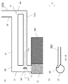
第1の実施の形態における冷却装置1000の構成について説明する。図1は、冷却装置1000の構成を示す図である。図1(a)は、冷却装置1000の構成を示す正面図である。図1(b)は、冷却装置1000の構成を示す側面図である。図2は、冷却装置1000の気相管および戻り管付近の部分拡大図である。図1および図2には、鉛直方向Gを矢印で示している。
<First Embodiment>
The configuration of the cooling device 1000 in the first embodiment will be described. FIG. 1 is a diagram illustrating a configuration of the cooling device 1000. FIG. 1A is a front view showing the configuration of the cooling device 1000. FIG. 1B is a side view showing the configuration of the cooling device 1000. FIG. 2 is a partially enlarged view of the vicinity of the vapor phase pipe and the return pipe of the cooling device 1000. 1 and 2, the vertical direction G is indicated by an arrow.

図1に示されるように、冷却装置1000は、受熱部10と、放熱部20と、気相管30と、液相管40と、戻り管50とを備えている。冷却装置1000は、自然循環方式が採用された冷却装置である。   As shown in FIG. 1, the cooling device 1000 includes a heat receiving part 10, a heat radiating part 20, a gas phase pipe 30, a liquid phase pipe 40, and a return pipe 50. The cooling device 1000 is a cooling device employing a natural circulation method.

冷却装置1000のうち、受熱部10は建物内に設置され、放熱部20は建物外に設置される。そして、受熱部10は、発熱部200に取り付けられている。発熱部200も建物内に配置されている。受熱部10および放熱部20は、2本の配管(気相管30および液相管40)によって、連通されている。   In the cooling device 1000, the heat receiving unit 10 is installed in the building, and the heat radiating unit 20 is installed outside the building. The heat receiving unit 10 is attached to the heat generating unit 200. The heat generating part 200 is also arranged in the building. The heat receiving part 10 and the heat radiating part 20 are communicated with each other by two pipes (a gas phase pipe 30 and a liquid phase pipe 40).

冷却装置1000は、受熱部10および放熱部20の間を循環する冷媒(Condensation preparations)を有する。すなわち、受熱部10および放熱部20の内部には、空洞が設けられている。また、冷媒は、受熱部10、放熱部20、気相管30、液相管40および戻り管50により形成される閉鎖空間内に、密閉された状態で閉じ込められる。この冷媒は、密閉された状態で、受熱部10および放熱部20の間を、気相管30、液相管40および戻り管50を介して、循環する。   The cooling device 1000 includes refrigerant (condensation preparations) that circulates between the heat receiving unit 10 and the heat radiating unit 20. That is, a cavity is provided inside the heat receiving unit 10 and the heat radiating unit 20. Further, the refrigerant is confined in a closed state in a closed space formed by the heat receiving unit 10, the heat radiating unit 20, the gas phase tube 30, the liquid phase tube 40, and the return tube 50. The refrigerant circulates between the heat receiving unit 10 and the heat radiating unit 20 through the gas phase tube 30, the liquid phase tube 40, and the return tube 50 in a sealed state.

冷媒は、例えば高分子材料などにより構成されており、高温になると気化し、低温になると液化する特性を有している。また、情報通信機器での使用を考え、冷媒には絶縁性のものを使用する。具体的には、HFC(hydro fluorocarbon:ハイドロフルオロカーボン)や、HFE(hydro fluor ether:ハイドロフルオロエーテル)を用いているが、材料はこれに限定されない。   The refrigerant is made of, for example, a polymer material, and has a characteristic of vaporizing at a high temperature and liquefying at a low temperature. In consideration of use in information communication equipment, an insulating refrigerant is used. Specifically, HFC (hydrofluorocarbon) or HFE (hydrofluoroether) is used, but the material is not limited to this.

冷却装置1000の前記閉鎖空間内に冷媒を充填する方法については、次の通りである。まず、受熱部10および放熱部40の内部空洞と、気相管30と、液相管40と、戻り管50とにより形成される閉鎖空間内に冷媒を注入する。次に、真空ポンプ(不図示)などを用いて、前記閉鎖空間内から空気を排除して、この当該閉鎖空間内に冷媒を密閉する。これにより、前記空間内の圧力は冷媒の飽和蒸気圧と等しくなり、前記閉鎖空間内に密閉された冷媒の沸点が室温近傍となる。以上の通り、冷却装置1000の前記閉鎖空間内に冷媒を充填する方法を説明した。   The method for filling the refrigerant in the closed space of the cooling device 1000 is as follows. First, the refrigerant is injected into a closed space formed by the internal cavities of the heat receiving unit 10 and the heat radiating unit 40, the gas phase tube 30, the liquid phase tube 40, and the return tube 50. Next, a vacuum pump (not shown) or the like is used to exclude air from the closed space, and the refrigerant is sealed in the closed space. Thereby, the pressure in the space becomes equal to the saturated vapor pressure of the refrigerant, and the boiling point of the refrigerant sealed in the closed space becomes near room temperature. As described above, the method of filling the refrigerant in the closed space of the cooling device 1000 has been described.

図1に示されるように、受熱部10は、発熱部200に取り付けられ、発熱部200の熱を受熱する。   As shown in FIG. 1, the heat receiving unit 10 is attached to the heat generating unit 200 and receives heat from the heat generating unit 200.

ここで、発熱部200は、例えばラックである。このラックは、例えば、高温熱量を出す複数の情報通信機器(サーバ等)を収容する。ラックは、収容体とも呼ばれる。ラックは、例えば、多くの情報通信機器の収容に使用されている19インチラックである。19インチラックには、JIS規格(日本工業規格)に適合したものや、EIA規格(米国電子工業会規格)に適合したものを用いることができる。なお、本実施の形態では、発熱部200に19インチラックを使用すると説明したが、これに類するラックであれば発熱部200に適用できる。   Here, the heat generating unit 200 is, for example, a rack. This rack accommodates, for example, a plurality of information communication devices (such as servers) that generate high-temperature heat. The rack is also called a container. The rack is, for example, a 19-inch rack used to accommodate many information communication devices. As the 19-inch rack, one that conforms to the JIS standard (Japanese Industrial Standard) or one that conforms to the EIA standard (American Electronic Industries Association standard) can be used. In the present embodiment, it is described that a 19-inch rack is used for the heat generating unit 200, but any rack similar to this can be applied to the heat generating unit 200.

受熱部10は、具体的には、発熱部200としてのラックの側面(排気側)に取り付けられている。受熱部10は、気相管30および液相管40を介して、放熱部20に接続されている。このとき、受熱部10は、放熱部20よりも鉛直方向Gの下方側に、配置されている。   Specifically, the heat receiving unit 10 is attached to a side surface (exhaust side) of a rack as the heat generating unit 200. The heat receiving unit 10 is connected to the heat radiating unit 20 via the gas phase tube 30 and the liquid phase tube 40. At this time, the heat receiving unit 10 is disposed on the lower side in the vertical direction G than the heat radiating unit 20.

受熱部10は、液相冷媒を蓄溜する。受熱部10は、発熱部200の熱を受熱(吸熱)することによって、液相冷媒を気相冷媒に相変化させる。この気相冷媒は、気相管30を介して、放熱部40へ流入される。   The heat receiving unit 10 stores liquid phase refrigerant. The heat receiving unit 10 receives the heat of the heat generating unit 200 (heat absorption), thereby changing the phase of the liquid phase refrigerant to a gas phase refrigerant. The gas-phase refrigerant flows into the heat radiating unit 40 via the gas-phase tube 30.

受熱部10の材料には、好ましくは、例えば、熱伝導率の高いアルミニウムや銅が用いられる。ただし、受熱部10の材料は、アルミニウムや銅に限定されない。   For example, aluminum or copper having high thermal conductivity is preferably used as the material of the heat receiving unit 10. However, the material of the heat receiving part 10 is not limited to aluminum or copper.

受熱部10内の具体的な構成を説明する。受熱部10は、上部ヘッダ11と、下部ヘッダ12と、複数のチューブ13と、複数のフィン14とを備えている。   A specific configuration in the heat receiving unit 10 will be described. The heat receiving unit 10 includes an upper header 11, a lower header 12, a plurality of tubes 13, and a plurality of fins 14.

上部ヘッダ11は、下部ヘッダ12よりも、鉛直方向Gの上方側に配置されている。上部ヘッダ11内は、空洞となっている。上部ヘッダ11は、気相管30に接続されている。   The upper header 11 is arranged above the lower header 12 in the vertical direction G. The upper header 11 is hollow. The upper header 11 is connected to the gas phase tube 30.

下部ヘッダ12は、上部ヘッダ11よりも、鉛直方向Gの下方側に配置されている。下部ヘッダ12内は、空洞となっている。下部ヘッダ12は、液相管40に接続されている。   The lower header 12 is arranged below the upper header 11 in the vertical direction G. The lower header 12 is hollow. The lower header 12 is connected to the liquid phase tube 40.

複数のチューブ13の各々は、上部ヘッダ11および下部ヘッダ12を連結する。   Each of the plurality of tubes 13 connects the upper header 11 and the lower header 12.

複数のフィン14は、チューブ13の間に設けられている。各フィン14は、各チューブ13の間に設けられる。これらのフィン14は、高温になった送風から熱を奪い、チューブ13内の冷媒に、受熱した熱を伝える。受熱した冷媒は、液相から気相に相変化し、チューブ13内を上昇する。   The plurality of fins 14 are provided between the tubes 13. Each fin 14 is provided between each tube 13. These fins 14 take away heat from the high-temperature air and transmit the received heat to the refrigerant in the tube 13. The refrigerant that has received heat undergoes a phase change from the liquid phase to the gas phase, and rises in the tube 13.

なお、フィン14は、複数の羽により構成されており、複数の羽の間には空気が通ることができるように構成されている。すなわち、フィン14の領域内では、受熱部10の一方の主面から他方の主面に向けて、空気が通り抜けることができる。   In addition, the fin 14 is comprised by the several wing | blade and is comprised so that air can pass between several wing | blades. That is, in the region of the fin 14, air can pass from one main surface of the heat receiving unit 10 toward the other main surface.

図1に示されるように、放熱部20は、受熱部10よりも鉛直方向Gの上方側に設けられている。放熱部20は、気相管30および液相管40を介して、受熱部10に接続されている。放熱部20の上部(鉛直方向Gの上方側)には、気相管30が接続されている。また、放熱部20の下部(鉛直方向Gの下方側)には、液相管40が接続されている。放熱部20は、受熱部10内の液相冷媒が相変化した気相冷媒を介して流入される発熱部100の熱を放熱する。なお、受熱部10内の液相冷媒は、受熱部10により発熱部200の熱を受熱することによって、気相冷媒に相変化する。   As shown in FIG. 1, the heat radiating unit 20 is provided above the heat receiving unit 10 in the vertical direction G. The heat radiating unit 20 is connected to the heat receiving unit 10 via the gas phase tube 30 and the liquid phase tube 40. A gas phase tube 30 is connected to the upper part of the heat radiating unit 20 (above the vertical direction G). In addition, a liquid phase tube 40 is connected to the lower part of the heat radiating unit 20 (the lower side in the vertical direction G). The heat radiating unit 20 radiates the heat of the heat generating unit 100 that flows in via the gas phase refrigerant in which the liquid phase refrigerant in the heat receiving unit 10 has changed phase. In addition, the liquid phase refrigerant in the heat receiving unit 10 changes into a gas phase refrigerant by receiving heat of the heat generating unit 200 by the heat receiving unit 10.

放熱部20は、気相冷媒を介して流入される発熱部200の熱を放熱することによって、気相冷媒を凝縮して、液相冷媒に相変化させる。すなわち、気相冷媒により輸送された熱は、外部のファンやチラー(chiller)等の冷却機器(不図示)から供給される空気や水に放熱される。この放熱により、気相冷媒は、凝縮して、液相冷媒に相変化する。そして、放熱部20で生じた液相冷媒は、液相管40を介して、受熱部10の下部ヘッダ12へ流入する。   The heat radiating unit 20 condenses the gas phase refrigerant and changes the phase to a liquid phase refrigerant by radiating the heat of the heat generating unit 200 that flows in via the gas phase refrigerant. That is, heat transported by the gas-phase refrigerant is radiated to air or water supplied from a cooling device (not shown) such as an external fan or chiller. Due to this heat dissipation, the gas-phase refrigerant is condensed and changes into a liquid-phase refrigerant. Then, the liquid phase refrigerant generated in the heat radiating unit 20 flows into the lower header 12 of the heat receiving unit 10 through the liquid phase tube 40.

自然循環方式の冷却装置1000では、気相冷媒と液相冷媒の密度差を利用して冷媒を循環させるため、密度の大きい液相冷媒を生じさせる放熱部20を、受熱部10よりも、鉛直方向Gの上方に、配置する必要がある。   In the natural circulation type cooling device 1000, since the refrigerant is circulated using the difference in density between the gas-phase refrigerant and the liquid-phase refrigerant, the heat dissipating unit 20 that generates the liquid-phase refrigerant having a high density is arranged more vertically than the heat receiving unit 10. It is necessary to arrange it above the direction G.

また、放熱部20は、通常、情報通信機器が設置される建物に設けられているチラーやファンなど(冷却機器の一種)に応じて、配置される。このため、放熱部20は、水平方向(すなわち、鉛直方向Gに対して垂直な方向)で、受熱部10から離れた位置に、配置されることが多い。   Moreover, the heat radiation part 20 is normally arrange | positioned according to the chiller, the fan, etc. (a kind of cooling device) provided in the building where the information communication equipment is installed. For this reason, the heat radiation part 20 is often arranged at a position away from the heat receiving part 10 in the horizontal direction (that is, the direction perpendicular to the vertical direction G).

放熱部20の材料には、好ましくは、例えば、熱伝導率の高いアルミニウムや銅が用いられる。ただし、放熱部20の材料は、アルミニウムや銅に限定されない。   For example, aluminum or copper having high thermal conductivity is preferably used as the material of the heat radiating unit 20. However, the material of the heat radiation part 20 is not limited to aluminum or copper.

図1に示されるように、気相管30は、受熱部10および放熱部20に接続され、両者を連結する。気相管30の一端部は、受熱部10の上部ヘッダ11に接続される。気相管30の他端部は、放熱部20の上部に接続される。気相管30は、受熱部10で生じた気相冷媒を含む冷媒を、受熱部10から放熱部20へ流入させる。   As shown in FIG. 1, the gas phase tube 30 is connected to the heat receiving unit 10 and the heat radiating unit 20 to connect the two. One end of the gas phase tube 30 is connected to the upper header 11 of the heat receiving unit 10. The other end of the gas phase tube 30 is connected to the upper part of the heat radiating unit 20. The gas phase tube 30 causes the refrigerant including the gas phase refrigerant generated in the heat receiving unit 10 to flow from the heat receiving unit 10 to the heat radiating unit 20.

冷却装置1000は、多くの熱量を吸熱することが要求されている。受熱部10は、発熱部200の熱を確実に吸熱するために、多量の液相冷媒を蓄溜する必要がある。このため、受熱部10で発生した気相冷媒の中には、多量の液相冷媒が混入する。したがって、気相管30内を流れる冷媒には、気相冷媒だけでなく、液相冷媒も混在することになる。   The cooling device 1000 is required to absorb a large amount of heat. The heat receiving unit 10 needs to store a large amount of liquid phase refrigerant in order to reliably absorb the heat of the heat generating unit 200. For this reason, a large amount of liquid-phase refrigerant is mixed in the gas-phase refrigerant generated in the heat receiving unit 10. Therefore, the refrigerant flowing in the gas phase tube 30 includes not only the gas phase refrigerant but also the liquid phase refrigerant.

受熱部10および放熱部20は、一般的な自然循環方式の冷却装置において、互いに離れた位置に配置される。このため、受熱部10および放熱部20を接続する気相管30は、電気配線、ネットワーク線、空調機のための配線や配管等を避けながら、敷設される。つまり、気相管30は、本発明の冷却装置の設置フロアの平面方向(鉛直方向Gに対して平行方向)に延びる配管と、その配管の方向を曲げる曲がり管を有している。   The heat receiving unit 10 and the heat radiating unit 20 are arranged at positions separated from each other in a general natural circulation cooling device. For this reason, the gas phase pipe 30 connecting the heat receiving unit 10 and the heat radiating unit 20 is laid while avoiding electrical wiring, network lines, wiring and piping for an air conditioner, and the like. That is, the gas phase pipe 30 has a pipe extending in the plane direction (parallel to the vertical direction G) of the installation floor of the cooling device of the present invention and a bent pipe that bends the direction of the pipe.

また、特に、自然循環方式の冷却装置1000では、液相冷媒と気相冷媒の密度差を利用して動作する。このため、放熱部20は、受熱部10よりも鉛直方向Gの上方側に配置される。このため上方へ曲がる曲がり管(後述の上方曲がり管32)を有する。   In particular, the natural circulation type cooling apparatus 1000 operates by utilizing the difference in density between the liquid-phase refrigerant and the gas-phase refrigerant. For this reason, the heat radiating part 20 is disposed on the upper side in the vertical direction G with respect to the heat receiving part 10. For this reason, it has the bending pipe | tube (after-mentioned upward bending pipe | tube 32) which bends upwards.

ここで、気相管30の一例として、図1および図2に示されるように、気相管30が、上方管31と、上方曲がり管32と、連結管33とを有する場合について説明する。   Here, as an example of the gas phase tube 30, a case where the gas phase tube 30 includes an upper tube 31, an upper bent tube 32, and a connecting tube 33 will be described as shown in FIGS. 1 and 2.

上方管31は、受熱部10に接続されている。上方管31は、受熱部10から放熱部20側へ向けて鉛直方向Gの上方側に延びるように設けられている。   The upper pipe 31 is connected to the heat receiving unit 10. The upper pipe 31 is provided so as to extend upward in the vertical direction G from the heat receiving part 10 toward the heat radiating part 20 side.

上方曲がり管32は、放熱部20に接続されている。上方曲がり管32は、放熱部20から受熱部10側へ向けて鉛直方向Gの下方側に延びるように設けられている。   The upper bent pipe 32 is connected to the heat dissipation part 20. The upper bent pipe 32 is provided to extend downward in the vertical direction G from the heat radiating unit 20 toward the heat receiving unit 10.

連結管33は、上方管31および上方曲がり管32を接続する。連結管33は、鉛直方向Gに対して垂直方向に沿って延在する。   The connecting pipe 33 connects the upper pipe 31 and the upper bent pipe 32. The connecting pipe 33 extends along the vertical direction with respect to the vertical direction G.

図1に示されるように、液相管40は、受熱部10および放熱部20に接続され、両者を連結する。液相管40の一端部は、放熱部20の下部に接続される。液相管40の他端部は、受熱部10の下部ヘッダ12に接続される。   As shown in FIG. 1, the liquid phase tube 40 is connected to the heat receiving unit 10 and the heat radiating unit 20, and couples them together. One end of the liquid phase tube 40 is connected to the lower part of the heat radiating unit 20. The other end of the liquid phase tube 40 is connected to the lower header 12 of the heat receiving unit 10.

液相管40は、放熱部20により凝縮された液相冷媒を、放熱部20から受熱部10へ流入させる。すなわち、液相管40は、放熱部20により発熱部200の熱を放熱することによって気相冷媒が相変化した液相冷媒を、放熱部20から受熱部10へ流入させる。   The liquid phase tube 40 causes the liquid phase refrigerant condensed by the heat radiating unit 20 to flow from the heat radiating unit 20 to the heat receiving unit 10. That is, the liquid phase tube 40 causes the liquid phase refrigerant whose phase change has occurred in the gas phase refrigerant to flow from the heat radiating unit 20 to the heat receiving unit 10 by radiating the heat of the heat generating unit 200 by the heat radiating unit 20.

受熱部10および放熱部20は、一般的な自然循環方式の冷却装置において、互いに離れた位置に配置される。このため、受熱部10および放熱部20を接続する液相管40は、電気配線、ネットワーク線、空調機のための配線や配管等を避けながら、敷設される。つまり、液相管40は、本発明の冷却装置の設置フロアの平面方向(鉛直方向Gに対して平行方向)に延びる配管と、その配管の方向を曲げる曲がり管を有している。   The heat receiving unit 10 and the heat radiating unit 20 are arranged at positions separated from each other in a general natural circulation cooling device. For this reason, the liquid phase tube 40 connecting the heat receiving unit 10 and the heat radiating unit 20 is laid while avoiding electrical wiring, network lines, wiring and piping for an air conditioner, and the like. That is, the liquid phase tube 40 has a pipe extending in the plane direction (parallel to the vertical direction G) of the installation floor of the cooling device of the present invention and a bent pipe that bends the direction of the pipe.

図1および図2に示されるように、戻り管50は、気相管30に接続されている。より具体的には、戻り管50は、上方曲がり管32および連結管33を接続する接続部M1と、上方管31とに、接続されている。ここで、戻り管50は、気相管30が分岐した管とすることもできる。すなわち、気相管30は、上方曲がり管32および連結管33を接続する接続部M1において分岐し、分岐した気相管(戻り管50)は、上方管31と合流する。このとき、上方曲がり管32および連結管33の接続部M1は、上方管31と戻り管50との接続部M2より、鉛直方向Gの上方に設けられている。戻り管50は、気相管50を流れる冷媒に含まれる液相冷媒を、受熱部10へ戻す。また、戻り管50とおよび上方管31は、接続部M2で、戻り管50の中心線と上方管31の中心線とが交わるように設けられている。   As shown in FIGS. 1 and 2, the return pipe 50 is connected to the gas phase pipe 30. More specifically, the return pipe 50 is connected to the connection part M1 that connects the upper bending pipe 32 and the connecting pipe 33 and the upper pipe 31. Here, the return pipe 50 may be a pipe branched from the gas phase pipe 30. That is, the gas phase pipe 30 branches at the connection portion M1 connecting the upper bent pipe 32 and the connecting pipe 33, and the branched gas phase pipe (return pipe 50) joins the upper pipe 31. At this time, the connection part M1 of the upper bending pipe 32 and the connecting pipe 33 is provided above the vertical direction G from the connection part M2 of the upper pipe 31 and the return pipe 50. The return pipe 50 returns the liquid phase refrigerant contained in the refrigerant flowing through the gas phase pipe 50 to the heat receiving unit 10. The return pipe 50 and the upper pipe 31 are provided so that the center line of the return pipe 50 and the center line of the upper pipe 31 intersect at the connection portion M2.

図1および図2に示されるように、戻り管50は、戻り管入口51と、戻り管出口52を有する。   As shown in FIGS. 1 and 2, the return pipe 50 has a return pipe inlet 51 and a return pipe outlet 52.

戻り管入口51は、上方曲がり管32および連結管33を接続する接続部M1に設けられている。戻り管入口51は、接続部M1において、上方曲がり管32の下面を開口して設けられる。このように、戻り管入口51を設けることにより、上方曲がり管32において、気相冷媒は鉛直方向Gの上方側へ上昇し、液相冷媒は鉛直方向Gの下方側へ下降する。このため、気相管50を流れる冷媒に含まれる液相冷媒を、効率よく戻り管50へ流入させることができる。一方で、設置環境によっては、戻り管入口51を連結管33に設けても良い。   The return pipe inlet 51 is provided in a connection portion M1 that connects the upper bent pipe 32 and the connecting pipe 33. The return pipe inlet 51 is provided by opening the lower surface of the upper bent pipe 32 at the connection portion M1. As described above, by providing the return pipe inlet 51, the gas-phase refrigerant rises upward in the vertical direction G and the liquid-phase refrigerant falls downward in the vertical direction G in the upward bending pipe 32. For this reason, the liquid phase refrigerant contained in the refrigerant flowing through the gas phase pipe 50 can be efficiently introduced into the return pipe 50. On the other hand, the return pipe inlet 51 may be provided in the connection pipe 33 depending on the installation environment.

戻り管出口52は、上方管31の壁を開口して設けられている。このとき、上方管31と戻り管50との接続部M2は、上方曲がり管32および連結管33の接続部M1より、鉛直方向Gの下方に設けられている。戻り管出口52を上方管31の壁に設けることにより、戻り管50内を流れる液相冷媒が、気相管30の上方管31の内壁面を伝って鉛直方向Gの下方へ降下する。これにより、戻り管50内を流れる液相冷媒が、気相管30の上方管31内を上昇する気相冷媒と干渉することを抑止することができる。   The return pipe outlet 52 is provided by opening the wall of the upper pipe 31. At this time, the connection part M2 between the upper pipe 31 and the return pipe 50 is provided below the vertical direction G from the connection part M1 of the upper bending pipe 32 and the connecting pipe 33. By providing the return pipe outlet 52 on the wall of the upper pipe 31, the liquid refrigerant flowing in the return pipe 50 descends in the vertical direction G along the inner wall surface of the upper pipe 31 of the gas phase pipe 30. Thereby, it is possible to prevent the liquid-phase refrigerant flowing in the return pipe 50 from interfering with the gas-phase refrigerant rising in the upper pipe 31 of the gas-phase pipe 30.

ここで、戻り管50の配管径(または、配管内側の断面積)が大きすぎる場合、気相管30の上方管31内を上昇する気相冷媒が戻り管出口52から流入することも考えられる。これに関して、気相冷媒は、同じ質量あたりの体積が液相冷媒より大きいため、戻り管50の配管径(または、配管内側の断面積)は気相管30の配管径(または、配管内側の断面積)より小さいことが望ましい。   Here, when the pipe diameter of the return pipe 50 (or the cross-sectional area inside the pipe) is too large, it is also conceivable that the gas phase refrigerant rising in the upper pipe 31 of the gas phase pipe 30 flows from the return pipe outlet 52. . In this regard, since the vapor phase refrigerant has a larger volume per mass than the liquid phase refrigerant, the pipe diameter of the return pipe 50 (or the cross-sectional area inside the pipe) is the pipe diameter of the gas phase pipe 30 (or inside the pipe). It is desirable that it is smaller than the cross-sectional area.

逆に、戻り管50の配管径(または、配管内側の断面積)が小さすぎる場合、戻る液相冷媒の流動を妨げるため、所望の効果を得られないことも考えられる。気相冷媒が巻き込む液相冷媒量は、その冷却装置が受ける熱量や、寸法に依存するために一律に決めることは難しい。そこで、少なくとも気相冷媒と同質量程度の液相冷媒は輸送されるため、気相冷媒の質量流量と同程度の質量流量が戻り管50に流れるようにすることが、好ましい。つまり、好ましくは、戻り管50と気相管30の配管径比が、液相冷媒と気相冷媒の密度比以上になるように、戻り管7の配管径を決める。   On the other hand, when the pipe diameter of the return pipe 50 (or the cross-sectional area inside the pipe) is too small, the flow of the returning liquid phase refrigerant is hindered, so that a desired effect may not be obtained. The amount of the liquid phase refrigerant that the gas phase refrigerant entrains depends on the amount of heat received by the cooling device and the size, and it is difficult to determine it uniformly. Therefore, since at least the liquid phase refrigerant having the same mass as the gas phase refrigerant is transported, it is preferable that the mass flow rate equivalent to the mass flow rate of the gas phase refrigerant flows in the return pipe 50. That is, preferably, the pipe diameter of the return pipe 7 is determined so that the pipe diameter ratio between the return pipe 50 and the gas phase pipe 30 is equal to or higher than the density ratio between the liquid phase refrigerant and the gas phase refrigerant.

たとえば、多くの冷却装置で利用されている冷媒であるR134aの場合、温度−10℃、圧力約200パスカルの時、液体冷媒の密度が約10キログラム毎立方メートル、気相冷媒の密度が約1330キログラム毎立方メートルとなる。すなわち、気体の密度が、液体の密度に対して約133倍程度大きい。このため、液相管40の配管径は、気相管30の配管径の約133分の1以上であることを望ましい。多くの冷媒の場合、R134aのように、液相冷媒の方が気相冷媒より数100倍程度密度が大きいため、戻り管50の配管径を、気相管30の配管径の100分1以上にすることが望ましい。   For example, in the case of R134a, which is a refrigerant used in many cooling devices, when the temperature is −10 ° C. and the pressure is about 200 Pascal, the density of the liquid refrigerant is about 10 kilograms per cubic meter and the density of the gas phase refrigerant is about 1330 kilograms. Every cubic meter. That is, the density of the gas is about 133 times larger than the density of the liquid. For this reason, it is desirable that the pipe diameter of the liquid phase pipe 40 is about 1/133 or more of the pipe diameter of the gas phase pipe 30. In the case of many refrigerants, the liquid phase refrigerant has a density several hundred times larger than that of the gas phase refrigerant, as in R134a, so that the pipe diameter of the return pipe 50 is 1/100 or more of the pipe diameter of the gas phase pipe 30. It is desirable to make it.

図3は、本発明の第1の実施の形態における冷却装置の変形例の構成を示す図である。なお、図3では、図1、2で示した各構成要素と同等の構成要素には、図1、2に示した符号と同等の符号を付している。上記例では、気相管30が、上方管31、上方曲がり管32及び連結管33を有する場合について説明したが、他の構成の場合も考えられる。例えば、図3に示すように、気相管30が、一か所で屈曲している構成である。この構成の場合、気相管30は、放熱部20との接続部と屈曲箇所との間で分岐する。また、この構成の場合、気相管30は、屈曲箇所の下方で合流する。   FIG. 3 is a diagram showing a configuration of a modification of the cooling device according to the first embodiment of the present invention. In FIG. 3, constituent elements equivalent to those shown in FIGS. 1 and 2 are given the same reference numerals as those shown in FIGS. In the above example, the case where the gas phase pipe 30 includes the upper pipe 31, the upper bent pipe 32, and the connecting pipe 33 has been described, but other configurations are also conceivable. For example, as shown in FIG. 3, the gas phase tube 30 is bent at one place. In the case of this configuration, the gas phase tube 30 branches between a connection portion with the heat radiating portion 20 and a bent portion. In the case of this configuration, the gas phase tubes 30 merge below the bent portion.

次に、冷却装置1000の動作について説明する。図4は、冷却装置1000の動作を説明するための概略図である。図5は、冷却装置1000の気相管30および戻り管50付近の部分拡大図であって、冷却装置1000の動作を説明するための図である。なお、便宜上、図4では戻り管50を省略している。図4および図5には、鉛直方向Gを矢印で示している。   Next, the operation of the cooling device 1000 will be described. FIG. 4 is a schematic diagram for explaining the operation of the cooling device 1000. FIG. 5 is a partially enlarged view of the vicinity of the vapor phase pipe 30 and the return pipe 50 of the cooling device 1000 for explaining the operation of the cooling device 1000. For convenience, the return pipe 50 is omitted in FIG. 4 and 5, the vertical direction G is indicated by an arrow.

まず、受熱部10は、発熱部200(例えば、ラック(不図示))の熱(例えば、ラック内の情報通信機器(不図示)の排熱)を受熱する。受熱部10が発熱部200の熱を吸熱すると、液相冷媒が沸騰して気相状態になり気相冷媒へ相変化する。気化した気相冷媒は、液相冷媒よりも密度が小さいため、その浮力により鉛直方向Gの上方へ上昇し、受熱部10の上部ヘッダ11を通って気相管30へ流入する。   First, the heat receiving unit 10 receives heat of a heat generating unit 200 (for example, a rack (not shown)) (for example, exhaust heat of an information communication device (not shown) in the rack). When the heat receiving unit 10 absorbs the heat of the heat generating unit 200, the liquid phase refrigerant boils, enters a gas phase state, and changes into a gas phase refrigerant. Since the vaporized vapor refrigerant has a density lower than that of the liquid refrigerant, the vaporized refrigerant rises upward in the vertical direction G due to its buoyancy and flows into the vapor pipe 30 through the upper header 11 of the heat receiving unit 10.

ここで、冷却装置1000は、多くの熱量を吸熱することが要求されている。このため、受熱部10は、発熱部200の熱を確実に吸熱するために、多量の液相冷媒を蓄溜する必要がある。したがって、受熱部10で発生した気相冷媒の中には、多量の液相冷媒が混入する。したがって、気相管30内を流れる冷媒には、気相冷媒だけでなく、液相冷媒も混在する。   Here, the cooling device 1000 is required to absorb a large amount of heat. For this reason, the heat receiving unit 10 needs to store a large amount of liquid-phase refrigerant in order to reliably absorb the heat of the heat generating unit 200. Therefore, a large amount of liquid phase refrigerant is mixed in the gas phase refrigerant generated in the heat receiving unit 10. Therefore, the refrigerant flowing in the gas phase pipe 30 includes not only the gas phase refrigerant but also the liquid phase refrigerant.

次に、図4の矢印P1に示すように、発熱部200の熱を吸収した気相冷媒を含む冷媒は、気相管30内を、放熱部20へ向かって上昇する。この間、発熱部200の熱を吸収した気相冷媒を含む冷媒は、上方管31、連結管33および上方曲がり管32を順次通って、放熱部20へ向かう。   Next, as indicated by an arrow P <b> 1 in FIG. 4, the refrigerant including the gas phase refrigerant that has absorbed the heat of the heat generating unit 200 rises in the gas phase tube 30 toward the heat radiating unit 20. During this time, the refrigerant including the gas-phase refrigerant that has absorbed the heat of the heat generating unit 200 sequentially passes through the upper pipe 31, the connecting pipe 33, and the upper bent pipe 32 toward the heat radiating unit 20.

ここで、前述の通り、戻り管50が、上方曲がり管32および連結管33を接続する接続部M1と、上方管31とに、接続されている。このとき、上方曲がり管32および連結管33の接続部M1は、上方管31と戻り管50との接続部M2より、鉛直方向Gの上方に設けられている。   Here, as described above, the return pipe 50 is connected to the connection portion M1 that connects the upper bending pipe 32 and the connecting pipe 33 and the upper pipe 31. At this time, the connection part M1 of the upper bending pipe 32 and the connecting pipe 33 is provided above the vertical direction G from the connection part M2 of the upper pipe 31 and the return pipe 50.

したがって、図5の矢印P3に示すように、発熱部200の熱を吸収した気相冷媒を含む冷媒のうち、液相冷媒RCQは、その自重により、上方曲がり管32から戻り管50へ、戻り管入口51を介して、上方曲がり管32および戻り管50の内壁を伝って下降する。このように、発熱部200の熱を吸収した気相冷媒を含む冷媒のうち、液相冷媒RCQは、気相管40内の気相冷媒の流動を妨げることなく、気相冷媒と逆方向に移動する。   Therefore, as shown by an arrow P3 in FIG. 5, among the refrigerants including the gas phase refrigerant that has absorbed the heat of the heat generating unit 200, the liquid phase refrigerant RCQ returns from the upper bent pipe 32 to the return pipe 50 due to its own weight. The pipe descends through the pipe inlet 51 along the inner walls of the upper bent pipe 32 and the return pipe 50. As described above, among the refrigerants including the gas phase refrigerant that has absorbed the heat of the heat generating unit 200, the liquid phase refrigerant RCQ does not interfere with the flow of the gas phase refrigerant in the gas phase pipe 40 and is in the opposite direction to the gas phase refrigerant. Moving.

もし、戻り管50が設けられていない場合、発熱部200の熱を吸収した気相冷媒を含む冷媒のうち、液相冷媒は、気相冷媒の流れに干渉しながら、気相管30内を逆流する以外ないい。このため、気相管30内の気相冷媒の流動を著しく妨げ、冷却装置の熱輸送能力を低下させる。   If the return pipe 50 is not provided, the liquid-phase refrigerant out of the refrigerant containing the gas-phase refrigerant that has absorbed the heat of the heat generating unit 200 interferes with the flow of the gas-phase refrigerant, while passing through the gas-phase pipe 30. There is no other way than backflow. For this reason, the flow of the gas-phase refrigerant in the gas-phase pipe 30 is significantly hindered, and the heat transport capability of the cooling device is lowered.

これに対して、本発明の冷却装置1000では、戻り管50を設けることにより、発熱部200の熱を吸収した気相冷媒を含む冷媒のうち、液相冷媒RCQは、図5の矢印P4で示すように、上方曲がり管32および戻り管50の内壁を伝って下降しながら、戻り管入口51から戻り管50内に流入する。戻り管50内を流れる液相冷媒RCQは、当該液相冷媒の自重により受熱部10側へ移動し、戻り管出口52に到達し、戻り管出口52を介して気相管30の上方管31内に流入する。   On the other hand, in the cooling device 1000 of the present invention, by providing the return pipe 50, the liquid-phase refrigerant RCQ among the refrigerants including the gas-phase refrigerant that has absorbed the heat of the heat generating portion 200 is indicated by the arrow P4 in FIG. As shown, the air flows into the return pipe 50 from the return pipe inlet 51 while descending along the upper bent pipe 32 and the inner wall of the return pipe 50. The liquid phase refrigerant RCQ flowing in the return pipe 50 moves toward the heat receiving unit 10 due to its own weight, reaches the return pipe outlet 52, and passes through the return pipe outlet 52 to the upper pipe 31 of the gas phase pipe 30. Flows in.

戻り管出口52は上方管31の壁面に設けられており、上方管31は鉛直方向Gの上方側へ延びるように設けられている。このため、図5の矢印P5に示されるように、戻り管出口52を介して気相管30の上方管31内に流入する液相冷媒は、すぐに上方管31内を、当該上方管31の内壁を伝って、鉛直方向Gの下方側へ降下する。   The return pipe outlet 52 is provided on the wall surface of the upper pipe 31, and the upper pipe 31 is provided so as to extend upward in the vertical direction G. For this reason, as indicated by an arrow P5 in FIG. 5, the liquid refrigerant flowing into the upper pipe 31 of the gas phase pipe 30 via the return pipe outlet 52 immediately passes through the upper pipe 31. It descends to the lower side of the vertical direction G along the inner wall.

つまり、液相冷媒は、上方管31の内壁を伝って鉛直方向Gの下方側へ降下するので、上方管31内を上昇する気相冷媒と、上方管内を下降する液相冷媒の干渉を、最小限に抑えることができる。   That is, since the liquid refrigerant descends to the lower side in the vertical direction G along the inner wall of the upper pipe 31, interference between the gas phase refrigerant that rises in the upper pipe 31 and the liquid refrigerant that descends in the upper pipe, Can be minimized.

気相管30の上方管31に戻った液相冷媒は、受熱部10の上部ヘッダ11に流入し、受熱部30内で発熱部200の熱を吸熱することで気相冷媒に相変化し、受熱部10および放熱部20の間を循環する冷媒として使用される。   The liquid refrigerant returned to the upper pipe 31 of the gas phase tube 30 flows into the upper header 11 of the heat receiving unit 10 and changes the phase to the gas phase refrigerant by absorbing the heat of the heat generating unit 200 in the heat receiving unit 30. It is used as a refrigerant that circulates between the heat receiving unit 10 and the heat radiating unit 20.

戻り管50を設けることによって、上方曲がり管32を上昇する冷媒は、液相冷媒をほとんど含まず、ほぼ全てが気相冷媒となる。このため、気相管30のうちで接続部M1より鉛直方向Gの上方側(特に、曲がり部)では、発熱部200の熱を吸収した気相冷媒を含む冷媒のうち、液相冷媒と気相冷媒が、気相管30内で互いに干渉することはない。すなわち、発熱部200の熱を吸収した気相冷媒を含む冷媒のうち、液相冷媒が、気相管30内の曲がり部等で、気相管30内を上昇する気相冷媒の流動の妨げになることはない。   By providing the return pipe 50, the refrigerant rising up the upper bending pipe 32 contains almost no liquid phase refrigerant, and almost all of the refrigerant becomes gas phase refrigerant. For this reason, in the gas phase pipe 30 above the connection part M1 in the vertical direction G (particularly, the bent part), among the refrigerants including the gas phase refrigerant that has absorbed the heat of the heat generating part 200, the liquid phase refrigerant and the gas are included. The phase refrigerants do not interfere with each other in the gas phase tube 30. That is, among the refrigerants including the gas phase refrigerant that has absorbed the heat of the heat generating unit 200, the liquid phase refrigerant is hindered in the flow of the gas phase refrigerant that rises in the gas phase pipe 30 at a bent portion or the like in the gas phase pipe 30. Never become.

次に、上方曲がり管32を上昇する気相冷媒は、放熱部20内に流入する。放熱部20内に流入した気相冷媒は、放熱部20により冷却され、液化される。これにより、気相冷媒が液相冷媒に相変化する。この結果、気相冷媒によって運ばれた発熱部200の熱が放熱部20で放熱される。   Next, the gas-phase refrigerant rising up the upper bent pipe 32 flows into the heat radiating unit 20. The gas-phase refrigerant that has flowed into the heat radiating unit 20 is cooled and liquefied by the heat radiating unit 20. As a result, the gas-phase refrigerant changes into a liquid-phase refrigerant. As a result, the heat of the heat generating part 200 carried by the gas phase refrigerant is radiated by the heat radiating part 20.

液相冷媒は気相冷媒より密度が小さいので、放熱部20内で生じた液相冷媒は、放熱部20内を鉛直方向Gの下方側へ下降する。そして、液相冷媒は、放熱部20の下部に接続された液相管40内に流入する。   Since the liquid-phase refrigerant has a lower density than the gas-phase refrigerant, the liquid-phase refrigerant generated in the heat radiating unit 20 moves down in the vertical direction G in the heat radiating unit 20. Then, the liquid phase refrigerant flows into the liquid phase tube 40 connected to the lower part of the heat radiating unit 20.

次に、図4の矢印P2に示すように、液相管40内を流れる液相冷媒は、当該液相冷媒の自重により、液相管40内を鉛直方向Gの下方側へ下降し、受熱部10の下部ヘッダ12内に流入する。このようにして、受熱部10内に蓄溜されていた液相冷媒が、放熱部20を介して再び受熱部10に還流される。   Next, as shown by the arrow P2 in FIG. 4, the liquid phase refrigerant flowing in the liquid phase tube 40 descends in the liquid phase tube 40 downward in the vertical direction G by the weight of the liquid phase refrigerant, and receives heat. It flows into the lower header 12 of the section 10. In this manner, the liquid-phase refrigerant stored in the heat receiving unit 10 is returned to the heat receiving unit 10 through the heat radiating unit 20 again.

そして、還流された液相冷媒は、受熱部10で発熱部200の熱を吸熱して、気相冷媒へ相変化し、冷却装置1000の熱輸送に使用される。以降、同じ動作を繰り返す。   The refluxed liquid-phase refrigerant absorbs the heat of the heat generating unit 200 in the heat receiving unit 10 and changes in phase to a gas-phase refrigerant, and is used for heat transport of the cooling device 1000. Thereafter, the same operation is repeated.

このように、冷媒は、受熱部10、気相管30、放熱部20および液相管40を順次、循環する。すなわち、冷媒は、受熱部10により吸熱された発熱部200の熱を含んだ状態で受熱部10から放熱部20へ気相管30を介して流れ、放熱部20により発熱部200の熱を放熱された後に放熱部20から受熱部10へ液相管40を介して流れる。これにより、受熱部10により受熱された発熱部200の熱が放熱される。以上の通り、冷却装置1000は、受熱部10および放熱部20の間で、冷媒を相変化(液相←→気相)させながら循環させることにより、受熱部10により受熱される発熱部200の熱を冷却する。   In this manner, the refrigerant circulates through the heat receiving unit 10, the gas phase tube 30, the heat radiating unit 20, and the liquid phase tube 40 in order. That is, the refrigerant flows from the heat receiving unit 10 to the heat radiating unit 20 through the gas phase tube 30 in a state including the heat of the heat generating unit 200 absorbed by the heat receiving unit 10, and the heat radiating unit 20 radiates the heat of the heat generating unit 200. Then, the heat flows from the heat radiating unit 20 to the heat receiving unit 10 through the liquid phase tube 40. Thereby, the heat of the heat generating part 200 received by the heat receiving part 10 is radiated. As described above, the cooling device 1000 circulates the refrigerant between the heat receiving unit 10 and the heat radiating unit 20 while changing the phase (liquid phase ← → gas phase) of the heat generating unit 200 received by the heat receiving unit 10. Cool the heat.

また、戻り管50は、気相管30に接続されている。気相管30を流れる冷媒に含まれる液相冷媒は、戻り管入口51を介して戻り管50内に流入し、戻り管出口52を介して気相管30の受熱部10側に流入し、受熱部10へ戻る。このように、気相管30を流れる冷媒に含まれる液相冷媒は、気相管30を上昇する気相冷媒の流動に干渉することなく、受熱部10へ戻る。   The return pipe 50 is connected to the gas phase pipe 30. The liquid-phase refrigerant contained in the refrigerant flowing through the gas phase pipe 30 flows into the return pipe 50 through the return pipe inlet 51, flows into the heat receiving unit 10 side of the gas phase pipe 30 through the return pipe outlet 52, Return to the heat receiving unit 10. Thus, the liquid phase refrigerant contained in the refrigerant flowing through the gas phase pipe 30 returns to the heat receiving unit 10 without interfering with the flow of the gas phase refrigerant rising through the gas phase pipe 30.

以上、冷却装置1000の構成および動作について説明した。   The configuration and operation of the cooling device 1000 have been described above.

次に、本発明の第1の実施の形態における冷却装置1000の変形例である冷却装置1000Aについて説明する。図6は、冷却装置1000Aの構成を示す部分拡大図である。図6(a)は、冷却装置1000Aの構成を示す部分拡大正面図である。図6(b)は、冷却装置1000Aの構成を示す部分拡大側面図である。なお、図6では、図1〜5で示した各構成要素と同等の構成要素には、図1〜5に示した符号と同等の符号を付している。また、図6には、鉛直方向Gを矢印で示している。   Next, a cooling device 1000A that is a modification of the cooling device 1000 according to the first embodiment of the present invention will be described. FIG. 6 is a partially enlarged view showing the configuration of the cooling device 1000A. FIG. 6A is a partially enlarged front view showing the configuration of the cooling device 1000A. FIG. 6B is a partially enlarged side view showing the configuration of the cooling device 1000A. In FIG. 6, constituent elements that are equivalent to the constituent elements shown in FIGS. 1 to 5 are assigned the same reference numerals as those shown in FIGS. 1 to 5. In FIG. 6, the vertical direction G is indicated by an arrow.

図6(a)および図6(b)に示されるように、冷却装置1000Aは、受熱部10と、放熱部20と、気相管30Aと、液相管40と、戻り管50Aとを備えている。冷却装置1000Aは、自然循環方式が採用された冷却装置である。   As shown in FIGS. 6A and 6B, the cooling device 1000A includes a heat receiving part 10, a heat radiating part 20, a gas phase pipe 30A, a liquid phase pipe 40, and a return pipe 50A. ing. The cooling device 1000A is a cooling device employing a natural circulation method.

ここで、図1(a)、(b)と、図6(a)、(b)を比較する。図1(a)、(b)では、気相管30の上方管31は、受熱部10の上部から鉛直方向Gの上方側に延出されていた。また、戻り管50は、受熱部10の上方で、気相管30の上方管31に接続されていた。これに対して、図6(a)、(b)では、気相管30の上方管31は、受熱部10の上部から下部に亘り、鉛直方向Gの上方側に延在する。また、戻り管50は、受熱部10の下部側で、気相管30の上方管31に接続されている。   Here, FIG. 1 (a), (b) and FIG. 6 (a), (b) are compared. In FIGS. 1A and 1B, the upper pipe 31 of the gas phase pipe 30 extends from the upper part of the heat receiving unit 10 to the upper side in the vertical direction G. The return pipe 50 was connected to the upper pipe 31 of the gas phase pipe 30 above the heat receiving unit 10. On the other hand, in FIGS. 6A and 6B, the upper pipe 31 of the gas phase pipe 30 extends upward in the vertical direction G from the upper part to the lower part of the heat receiving part 10. The return pipe 50 is connected to the upper pipe 31 of the gas phase pipe 30 on the lower side of the heat receiving unit 10.

図6(a)および図6(b)に示されるように、戻り管50Aおよび上方管31の接続部M2は、受熱部10および気相管30の接続部よりも鉛直方向Gの下方に設けられている。なお、戻り管30Aおよび上方管31の接続部M2には、戻り管出口52が設けられている。   As shown in FIGS. 6A and 6B, the connecting portion M2 of the return pipe 50A and the upper pipe 31 is provided below the connecting portion of the heat receiving part 10 and the gas phase pipe 30 in the vertical direction G. It has been. Note that a return pipe outlet 52 is provided at the connection portion M2 of the return pipe 30A and the upper pipe 31.

これにより、気相管30A内を放熱部20へ向けて上昇する気相冷媒と、戻り管50Aから気相管30Aの上方管31に流入する液相冷媒とが、互いに干渉し合うことを、さらに低減することができる。   Thereby, the gas phase refrigerant rising in the gas phase pipe 30A toward the heat radiating unit 20 and the liquid phase refrigerant flowing into the upper pipe 31 of the gas phase pipe 30A from the return pipe 50A interfere with each other. Further reduction can be achieved.

以上、本発明の第1の実施の形態における冷却装置1000の変形例である冷却装置1000Aについて説明した。   Heretofore, the cooling device 1000A that is a modification of the cooling device 1000 according to the first embodiment of the present invention has been described.

以上の通り、本発明の第1の実施の形態における冷却装置1000は、受熱部10と、放熱部20と、液相管40と、気相管30とを備えている。受熱部10は、発熱部200からの熱を受熱する。放熱部20は、受熱部10より上方に設けられ、熱を放熱する。液相管40は、受熱部10と放熱部20とを接続する。気相管30は、受熱部10と放熱部20とを接続する。冷却装置1000は、受熱部10、放熱部20、液相管40及び気相管20を冷媒が循環する。そして、気相管30は、気相管30と放熱部20との接続部M1より下方で分岐する。また、分岐した気相管(戻り管50)は、分岐した箇所よりも下方(接続部M2)で合流する。   As described above, the cooling device 1000 according to the first embodiment of the present invention includes the heat receiving unit 10, the heat radiating unit 20, the liquid phase tube 40, and the gas phase tube 30. The heat receiving unit 10 receives heat from the heat generating unit 200. The heat radiating unit 20 is provided above the heat receiving unit 10 and radiates heat. The liquid phase tube 40 connects the heat receiving unit 10 and the heat radiating unit 20. The gas phase tube 30 connects the heat receiving unit 10 and the heat radiating unit 20. In the cooling device 1000, the refrigerant circulates through the heat receiving unit 10, the heat radiating unit 20, the liquid phase tube 40, and the gas phase tube 20. The gas phase tube 30 branches below the connection portion M1 between the gas phase tube 30 and the heat radiation unit 20. Further, the branched gas phase pipe (return pipe 50) joins below (the connecting portion M2) below the branched position.

このように、気相管30は、気相管30と放熱部20との接続部M1より下方で分岐する。また、分岐した気相管(戻り管50)は、分岐した箇所よりも下方(接続部M2)で合流する。すなわち、気相管30を流れる冷媒のうち液相冷媒は、気相管30とは別に、分岐した気相管(戻り管50)内を流れて、受熱部20へ戻る。したがって、気相管30内を流れる冷媒のうち気相冷媒は、気相管30内で、液相冷媒の流動に干渉されることなく、受熱部10から放熱部20へ流れる。また、分岐した気相管(戻り管50)を通って受熱部20へ戻った液相冷媒は、発熱部200の熱により再び気相冷媒へ相変化され、分岐した気相管(戻り管50)内を受熱部10から放熱部30へ向けて上昇する。   Thus, the gas phase tube 30 branches below the connection portion M1 between the gas phase tube 30 and the heat dissipation unit 20. Further, the branched gas phase pipe (return pipe 50) joins below (the connecting portion M2) below the branched position. That is, of the refrigerant flowing through the gas phase pipe 30, the liquid phase refrigerant flows in the branched gas phase pipe (return pipe 50) separately from the gas phase pipe 30 and returns to the heat receiving unit 20. Accordingly, among the refrigerant flowing in the gas phase pipe 30, the gas phase refrigerant flows from the heat receiving unit 10 to the heat radiating unit 20 without being interfered with the flow of the liquid phase refrigerant in the gas phase pipe 30. Further, the liquid-phase refrigerant that has returned to the heat receiving unit 20 through the branched gas-phase pipe (return pipe 50) is changed into the gas-phase refrigerant again by the heat of the heat-generating unit 200, and the branched gas-phase pipe (return pipe 50). ) Rises from the heat receiving portion 10 toward the heat radiating portion 30.

よって、液相冷媒および気相冷媒が互いに干渉することなく、気相管30内の気相冷媒を受熱部10から放熱部20へ円滑に流入させることができ、分岐した気相管(戻り管50)を介して気相管30内の液相冷媒を受熱部10へ戻すことができる。   Therefore, the liquid-phase refrigerant and the gas-phase refrigerant can smoothly flow in the gas-phase refrigerant in the gas-phase pipe 30 from the heat receiving part 10 to the heat-radiating part 20 without interfering with each other, and the branched gas-phase pipe (return pipe) 50), the liquid refrigerant in the gas phase tube 30 can be returned to the heat receiving unit 10.

したがって、本発明の冷却装置1000によれば、発熱部200を冷却する性能が低減することを抑止することができる。   Therefore, according to the cooling apparatus 1000 of this invention, it can suppress that the performance which cools the heat-emitting part 200 reduces.

本発明の第1の実施の形態における冷却装置1000において、気相管30は少なくとも1か所以上で屈曲しており、気相管30は、放熱部20と屈曲箇所の間で分岐し、屈曲箇所より下方で合流する。   In the cooling device 1000 according to the first embodiment of the present invention, the gas phase tube 30 is bent at at least one place, and the gas phase tube 30 is branched between the heat radiating portion 20 and the bent portion. Merge below the point.

このように、気相管30は、放熱部20と屈曲箇所の間で分岐し、屈曲箇所より下方で合流する。これにより、屈曲箇所に冷媒が溜まることを抑止できる。この結果、気相管30に屈曲箇所が設けられても、発熱部200を冷却する性能が低減することを抑止することができる。   Thus, the gas phase tube 30 branches between the heat radiating portion 20 and the bent portion, and merges below the bent portion. Thereby, it can suppress that a refrigerant | coolant accumulates in a bending location. As a result, even if the gas phase tube 30 is provided with a bent portion, it is possible to prevent the performance of cooling the heat generating portion 200 from being reduced.

本発明の第1の実施の形態における冷却装置1000は、受熱部10と、放熱部20と、気相管30と、液相管40と、戻り管50とを備えている。受熱部10は、液相冷媒を蓄溜する。受熱部10は、発熱部200に取り付けられる。受熱部10は、
発熱部200の熱を受熱する。放熱部20は、受熱部20よりも鉛直上方側に設けられている。放熱部20は、受熱部20により発熱部200の熱を受熱することによって、液相冷媒が相変化した気相冷媒を介して流入される発熱部200熱を放熱する。気相管30は、受熱部10および放熱部20に接続されている。気相管30は、気相冷媒を含む冷媒を受熱部10から放熱部20へ流す。液相管40は、受熱部10および放熱部20に接続されている。液相管40は、放熱部20により発熱部200の熱を放熱することによって気相冷媒が相変化した液相冷媒を放熱部20から受熱部10へ流入させる。戻り管50は、気相管30に接続されている。戻り管50は、気相管30を流れる冷媒に含まれる液相冷媒を受熱部10へ戻す。
The cooling device 1000 according to the first embodiment of the present invention includes a heat receiving part 10, a heat radiating part 20, a gas phase pipe 30, a liquid phase pipe 40, and a return pipe 50. The heat receiving unit 10 stores liquid phase refrigerant. The heat receiving unit 10 is attached to the heat generating unit 200. The heat receiving unit 10
The heat of the heat generating part 200 is received. The heat radiating part 20 is provided vertically above the heat receiving part 20. The heat radiating unit 20 radiates the heat of the heat generating unit 200 that flows in through the gas phase refrigerant in which the liquid phase refrigerant has changed by receiving the heat of the heat generating unit 200 by the heat receiving unit 20. The gas phase tube 30 is connected to the heat receiving unit 10 and the heat radiating unit 20. The gas phase pipe 30 causes the refrigerant containing the gas phase refrigerant to flow from the heat receiving unit 10 to the heat radiating unit 20. The liquid phase tube 40 is connected to the heat receiving unit 10 and the heat radiating unit 20. The liquid phase tube 40 causes the heat radiation unit 20 to dissipate heat from the heat generating unit 200, and causes the liquid phase refrigerant whose phase change has occurred in the gas phase refrigerant to flow from the heat radiation unit 20 to the heat receiving unit 10. The return pipe 50 is connected to the gas phase pipe 30. The return pipe 50 returns the liquid phase refrigerant contained in the refrigerant flowing through the gas phase pipe 30 to the heat receiving unit 10.

このように、戻り管50が、気相管30に接続され、気相管30を流れる冷媒に含まれる液相冷媒を受熱部10へ戻す。すなわち、気相管30を流れる冷媒のうち液相冷媒は、気相管30とは別に設けられた戻り管50内を流れて、受熱部20へ戻る。したがって、気相管30内を流れる冷媒のうち気相冷媒は、気相管30内で、液相冷媒の流動に干渉されることなく、受熱部10から放熱部20へ流れる。また、戻り管50を通って受熱部20へ戻った液相冷媒は、発熱部200の熱により再び気相冷媒へ相変化され、気相管30内を受熱部10から放熱部30へ向けて上昇する。   Thus, the return pipe 50 is connected to the gas phase pipe 30 and returns the liquid phase refrigerant contained in the refrigerant flowing through the gas phase pipe 30 to the heat receiving unit 10. That is, of the refrigerant flowing through the gas phase pipe 30, the liquid phase refrigerant flows through the return pipe 50 provided separately from the gas phase pipe 30 and returns to the heat receiving unit 20. Accordingly, among the refrigerant flowing in the gas phase pipe 30, the gas phase refrigerant flows from the heat receiving unit 10 to the heat radiating unit 20 without being interfered with the flow of the liquid phase refrigerant in the gas phase pipe 30. Further, the liquid-phase refrigerant that has returned to the heat receiving unit 20 through the return pipe 50 is phase-changed again to a gas-phase refrigerant by the heat of the heat generating unit 200, and the gas phase pipe 30 is directed from the heat receiving unit 10 toward the heat radiating unit 30. To rise.

よって、気相管30に曲がり部が設けられても、液相冷媒および気相冷媒が互いに干渉することなく、気相管30内の気相冷媒を受熱部10から放熱部20へ円滑に流入させることができ、戻り管50を介して気相管30内の液相冷媒を受熱部10へ戻すことができる。   Therefore, even when the gas phase pipe 30 is provided with a bent portion, the liquid phase refrigerant and the gas phase refrigerant do not interfere with each other, and the gas phase refrigerant in the gas phase pipe 30 smoothly flows from the heat receiving portion 10 to the heat radiating portion 20. The liquid refrigerant in the gas phase pipe 30 can be returned to the heat receiving unit 10 through the return pipe 50.

したがって、本発明の冷却装置1000によれば、気相管30に曲がり部が設けられても、発熱部200を冷却する性能が低減することを抑止することができる。   Therefore, according to the cooling device 1000 of the present invention, even if the gas phase tube 30 is provided with a bent portion, it is possible to prevent the performance of cooling the heat generating portion 200 from being reduced.

自然循環方式の冷却装置1000では、気相冷媒は、液相冷媒が混入された状態で、気相管5内を受熱部10から放熱部20へ向けて移動する。上述の通り、戻り管50を設けることにより、気相管30の上方曲がり管32内を降下する液相冷媒と、気相管30内を放熱部20へ向けて上昇する気相冷媒とが干渉することを防止し、熱輸送能力の低下を抑制できる。   In the natural circulation type cooling apparatus 1000, the gas phase refrigerant moves from the heat receiving part 10 toward the heat radiating part 20 in the gas phase pipe 5 in a state in which the liquid phase refrigerant is mixed. As described above, by providing the return pipe 50, the liquid-phase refrigerant that descends in the upper bent pipe 32 of the gas-phase pipe 30 interferes with the gas-phase refrigerant that rises in the gas-phase pipe 30 toward the heat radiating unit 20. Can be prevented, and a decrease in heat transport capability can be suppressed.

自然循環方式の冷却装置1000では、気相冷媒と液相冷媒の密度差を利用して動作させているため、放熱器20を、受熱器10より鉛直方向Gの上方側に配置しなくてはならない等の制約がある。このため、冷却装置1000の設置時には、当該冷却装置1000の動作を考慮した設置が求められる。   The natural circulation type cooling device 1000 is operated by utilizing the density difference between the gas-phase refrigerant and the liquid-phase refrigerant, so that the radiator 20 must be disposed above the heat receiver 10 in the vertical direction G. There are restrictions such as not becoming. For this reason, when installing the cooling apparatus 1000, installation in consideration of the operation of the cooling apparatus 1000 is required.

すなわち、さまざまなケーブルや配管があるサーバルームにおいて、複数の曲がり部を配管(特に気相管30)に設けても、熱輸送能力を低下させないために、設置時に考慮すべき項目を少なくすることができる。   That is, in a server room with various cables and pipes, even if a plurality of bent parts are provided in the pipe (especially the gas phase pipe 30), the heat transport capacity is not lowered, so that items to be considered at the time of installation are reduced. Can do.

また、冷却装置1000の配管(特に気相管30)を、当該冷却装置1000の内部動作を考えることなく、発熱部200(例えばラック)を収容するサーバルーム内の電源配線や空調機の配管やダクト等を避けて、設けることができる。このため、冷却装置1000を容易に設置することができる。   In addition, the piping of the cooling device 1000 (particularly, the gas phase tube 30) can be used without considering the internal operation of the cooling device 1000. It can be provided avoiding ducts and the like. For this reason, the cooling device 1000 can be easily installed.

また、前述の通り、本発明の冷却装置1000では、戻り管50を設けることによって、自重により降下して受熱部10側へ戻ろうとする液相冷媒と、放熱部20へ向けて上昇する気相冷媒とが、気相管30内で干渉することが抑制されている。このため、気相管30の配管径(配管内の断面積)をより小さくすることができる。これにより、冷却装置1000の設置事時に、当該冷却装置1000の取扱いが簡便になり、設置時のコストを低減することができる。   Further, as described above, in the cooling device 1000 of the present invention, by providing the return pipe 50, the liquid phase refrigerant that descends due to its own weight and returns to the heat receiving unit 10 side and the gas phase that rises toward the heat radiating unit 20. Interference with the refrigerant in the gas phase tube 30 is suppressed. For this reason, the piping diameter (cross-sectional area in piping) of the gaseous-phase pipe | tube 30 can be made smaller. Thereby, at the time of installation of the cooling device 1000, the handling of the cooling device 1000 becomes simple, and the cost at the time of installation can be reduced.

また、本発明の第1の実施の形態における冷却装置1000は、戻り管50を備えている。戻り管50は、気相管30から気相管30と放熱部20との接続部M1より下方で分岐され、分岐した箇所よりも下方(接続部M2)で気相管30に合流し、気相管30を流れる冷媒に含まれる液相冷媒を受熱部10へ戻す。気相管30は、上方管31と、上方曲がり管32と、連結管33とを有する。上方管31は、受熱部10に接続されている。上方管31は、受熱部10から放熱部20側へ向けて鉛直上方側に延びるように設けられている。上方曲がり管32は、放熱部20に接続されている。上方曲がり管32は、放熱部20から受熱部10側へ向けて鉛直下方側に延びるように設けられている。連結管33は、上方管31および上方曲がり管32を接続する。戻り管50は、上方曲がり管32および連結管33の接続部と、上方管31とに接続されている。上方曲がり管32および連結管33の接続部は、上方管31および戻り管50の接続部より、鉛直方向Gの上方に設けられている。   The cooling device 1000 according to the first embodiment of the present invention includes a return pipe 50. The return pipe 50 is branched from the gas phase pipe 30 below the connection part M1 between the gas phase pipe 30 and the heat radiating part 20, and joins the gas phase pipe 30 below the branched part (connection part M2). The liquid-phase refrigerant contained in the refrigerant flowing through the phase tube 30 is returned to the heat receiving unit 10. The gas phase tube 30 includes an upper tube 31, an upper bent tube 32, and a connecting tube 33. The upper pipe 31 is connected to the heat receiving unit 10. The upper pipe 31 is provided so as to extend vertically upward from the heat receiving part 10 toward the heat radiating part 20 side. The upper bent pipe 32 is connected to the heat dissipation part 20. The upper bent pipe 32 is provided so as to extend vertically downward from the heat radiating unit 20 toward the heat receiving unit 10 side. The connecting pipe 33 connects the upper pipe 31 and the upper bent pipe 32. The return pipe 50 is connected to the connection portion of the upper bent pipe 32 and the connecting pipe 33 and the upper pipe 31. A connecting portion between the upper bent pipe 32 and the connecting pipe 33 is provided above the connecting portion between the upper pipe 31 and the return pipe 50 in the vertical direction G.

このように、戻り管50は、上方曲がり管32および連結管33の接続部M1に、接続されている。上方管31は、受熱部10から放熱部20側へ向けて鉛直上方側に延びるように設けられている。これにより、発熱部200の熱を吸収した気相冷媒を含む冷媒のうち、液相冷媒は、上方曲がり管32および戻り管50の内壁を伝って自重により下降しながら、戻り管入口51(戻り管入口51は、上方曲がり管32および連結管33の接続部M1に配置されている。)から戻り管50内に流入する(図5の矢印P3)。したがって、発熱部200の熱を吸収した気相冷媒を含む冷媒のうち、液相冷媒を、円滑に気相管30の上方曲がり管32から戻り管50へ流入させることができる。   In this way, the return pipe 50 is connected to the connection portion M1 of the upper bent pipe 32 and the connecting pipe 33. The upper pipe 31 is provided so as to extend vertically upward from the heat receiving part 10 toward the heat radiating part 20 side. As a result, among the refrigerants including the gas-phase refrigerant that has absorbed the heat of the heat generating part 200, the liquid-phase refrigerant travels down the inner wall of the upper bent pipe 32 and the return pipe 50, and descends by its own weight, while returning to the return pipe inlet 51 (return). The pipe inlet 51 flows into the return pipe 50 (arrow P3 in FIG. 5) from the upper bent pipe 32 and the connection portion M1 of the connecting pipe 33. Therefore, among the refrigerants including the gas phase refrigerant that has absorbed the heat of the heat generating unit 200, the liquid phase refrigerant can smoothly flow from the upper bent pipe 32 of the gas phase pipe 30 into the return pipe 50.

また、戻り管50は、上方管31に接続されている。上方管31は、受熱部10から放熱部20側へ向けて鉛直上方側に延びるように設けられている。これにより、戻り管出口52を介して気相管30の上方管31内に流入する液相冷媒は、すぐに上方管31内を、当該上方管31の内壁を伝って自重により鉛直方向Gの下方側へ降下する(図5の矢印P5)。したがって、発熱部200の熱を吸収した気相冷媒を含む冷媒のうち、液相冷媒を、円滑に戻り管50から気相管30の上方管31へ流入させることができる。液相冷媒は、上方管31の内壁を伝って鉛直方向Gの下方側へ降下するので、上方管31内を上昇する気相冷媒と、上方管内を下降する液相冷媒との干渉を、最小限に抑えることができる。   The return pipe 50 is connected to the upper pipe 31. The upper pipe 31 is provided so as to extend vertically upward from the heat receiving part 10 toward the heat radiating part 20 side. As a result, the liquid-phase refrigerant flowing into the upper pipe 31 of the gas phase pipe 30 through the return pipe outlet 52 immediately passes through the inner wall of the upper pipe 31 in the vertical direction G in the vertical direction G. It descends downward (arrow P5 in FIG. 5). Therefore, among the refrigerants including the gas phase refrigerant that has absorbed the heat of the heat generating unit 200, the liquid phase refrigerant can smoothly flow from the return pipe 50 to the upper pipe 31 of the gas phase pipe 30. Since the liquid-phase refrigerant descends to the lower side in the vertical direction G along the inner wall of the upper pipe 31, interference between the gas-phase refrigerant rising in the upper pipe 31 and the liquid-phase refrigerant descending in the upper pipe is minimized. To the limit.

本発明の第1の実施の形態における冷却装置1000において、発熱部200は、複数の電子装置を収容するラックである。これにより、ラック内の複数の電子装置から生じる熱を、冷却することができる。   In the cooling device 1000 according to the first embodiment of the present invention, the heat generating unit 200 is a rack that houses a plurality of electronic devices. Thereby, the heat generated from the plurality of electronic devices in the rack can be cooled.

本発明の第1の実施の形態における冷却装置1000の変形例である冷却装置1000Aにおいて、戻り管30Aおよび上方管31の接続部M2は、受熱部10および気相管30の接続部よりも鉛直方向Gの下方に設けられている。   In cooling device 1000A, which is a modification of cooling device 1000 in the first embodiment of the present invention, connecting portion M2 of return pipe 30A and upper pipe 31 is perpendicular to the connecting portion of heat receiving portion 10 and vapor phase pipe 30. It is provided below the direction G.

これにより、気相管30A内を放熱部20へ向けて上昇する気相冷媒と、戻り管50Aから気相管30Aの上方管31に流入する液相冷媒とが、互いに干渉し合うことを、さらに低減することができる。   Thereby, the gas phase refrigerant rising in the gas phase pipe 30A toward the heat radiating unit 20 and the liquid phase refrigerant flowing into the upper pipe 31 of the gas phase pipe 30A from the return pipe 50A interfere with each other. Further reduction can be achieved.

<第2の実施の形態>
次に、本発明の第2の実施の形態における冷却装置1000Bの構成を説明する。図7は、冷却装置1000Bの構成を示す部分拡大側面図である。なお、図7では、図1〜6で示した各構成要素と同等の構成要素には、図1〜6に示した符号と同等の符号を付している。また、図7には、鉛直方向Gを矢印で示している。
<Second Embodiment>
Next, the configuration of the cooling device 1000B according to the second embodiment of the present invention will be described. FIG. 7 is a partially enlarged side view showing the configuration of the cooling device 1000B. In FIG. 7, constituent elements that are equivalent to the constituent elements shown in FIGS. 1 to 6 are assigned the same reference numerals as those shown in FIGS. 1 to 6. In FIG. 7, the vertical direction G is indicated by an arrow.

図7に示されるように、冷却装置1000Bは、受熱部10と、放熱部20と、気相管30と、液相管40と、戻り管50と、接続機構61、62とを備えている。冷却装置1000Bは、自然循環方式が採用された冷却装置である。   As shown in FIG. 7, the cooling device 1000 </ b> B includes a heat receiving part 10, a heat radiating part 20, a gas phase pipe 30, a liquid phase pipe 40, a return pipe 50, and connection mechanisms 61 and 62. . The cooling device 1000B is a cooling device that employs a natural circulation method.

ここで、図1(a)、(b)と、図7を比較する。図7では、接続機構61、62が設けられている点で、図1(a)、(b)と相違する。   Here, FIG. 1A and FIG. 1B are compared with FIG. 7 is different from FIGS. 1A and 1B in that connection mechanisms 61 and 62 are provided.

図7に示されるように、接続機構61は、気相管30の上方曲がり管32に設けられている。接続機構62は、気相管30の上方管31に設けられている。   As shown in FIG. 7, the connection mechanism 61 is provided in the upward bending pipe 32 of the gas phase pipe 30. The connection mechanism 62 is provided in the upper pipe 31 of the gas phase pipe 30.

少なくとも、気相管30の連結管33と、戻り管50と、接続部M1(戻り管入口51)と、接続部M2(戻り管出口52)とが、接続機構61および接続機構62の間に配置されるように、設けられている。接続機構61および接続機構62の間に設けられた気相管30の一部と戻り管50は、分離部として、気相管30に対して取り付けまたは取り外すことができる。接続機構61、62は、フランジ形状に形成されており、ガスケットやねじ等を用いて、分離部と気相管30と連結することができる。   At least the connecting pipe 33 of the gas phase pipe 30, the return pipe 50, the connection part M <b> 1 (return pipe inlet 51), and the connection part M <b> 2 (return pipe outlet 52) are between the connection mechanism 61 and the connection mechanism 62. It is provided to be arranged. A part of the gas phase pipe 30 provided between the connection mechanism 61 and the connection mechanism 62 and the return pipe 50 can be attached to or detached from the gas phase pipe 30 as a separation unit. The connection mechanisms 61 and 62 are formed in a flange shape, and can be connected to the separation unit and the gas phase tube 30 using a gasket, a screw, or the like.

このように、冷却装置1000Bでは、冷却装置1000Bの一部の構造を分離部として部品化し、これを接続構造61、62を用いて連結できるようにした。このため、本発明の設置環境ごとの個別設計や、設置工事時の微調整が必要なくなるので、大幅はコスト削減ができる。また、すでに設置された冷却装置であっても、接続構造61、62を通して、取り付けること可能であり、適用範囲を拡大することができる。   Thus, in the cooling device 1000B, a part of the structure of the cooling device 1000B is made into a part as a separation part, and this can be connected using the connection structures 61 and 62. For this reason, the individual design for each installation environment of the present invention and the fine adjustment at the time of installation work are not required, so that the cost can be greatly reduced. Moreover, even if it is a cooling device already installed, it can be attached through the connection structures 61 and 62, and an application range can be expanded.

なお、冷却装置1000Bの動作は、冷却装置1000の動作を同様である。   The operation of the cooling device 1000B is similar to the operation of the cooling device 1000.

以上の通り、本発明の第2の実施の形態における冷却装置1000Bにおいて、戻り管50は、気相管30から取り外すことができる。これにより、本発明の設置環境ごとの個別設計や、設置工事時の微調整が必要なくなるので、大幅はコスト削減ができる。また、すでに設置された冷却装置であっても、接続構造61、62を通して、取り付けること可能であり、適用範囲を拡大することができる。また、戻り管30付近が破損した場合であっても、すぐに交換することができる。   As described above, the return pipe 50 can be detached from the gas phase pipe 30 in the cooling device 1000B according to the second embodiment of the present invention. This eliminates the need for individual design for each installation environment of the present invention and fine adjustment at the time of installation work, so that cost can be greatly reduced. Moreover, even if it is a cooling device already installed, it can be attached through the connection structures 61 and 62, and an application range can be expanded. Even if the vicinity of the return pipe 30 is damaged, it can be immediately replaced.

<第3の実施の形態>
次に、本発明の第3の実施の形態における冷却装置1000Cの構成を説明する。図8は、冷却装置1000Cの構成を示す部分拡大側面図である。なお、図8では、図1〜7で示した各構成要素と同等の構成要素には、図1〜7に示した符号と同等の符号を付している。また、図8には、鉛直方向Gを矢印で示している。
<Third Embodiment>
Next, the configuration of the cooling device 1000C according to the third embodiment of the present invention will be described. FIG. 8 is a partially enlarged side view showing the configuration of the cooling device 1000C. In FIG. 8, constituent elements equivalent to those shown in FIGS. 1 to 7 are given the same reference numerals as those shown in FIGS. 1 to 7. In FIG. 8, the vertical direction G is indicated by an arrow.

図8に示されるように、冷却装置1000Cは、受熱部10と、放熱部20と、気相管30と、液相管40と、戻り管50Bと、屈曲部53とを備えている。冷却装置1000Cは、自然循環方式が採用された冷却装置である。   As shown in FIG. 8, the cooling device 1000 </ b> C includes a heat receiving part 10, a heat radiating part 20, a gas phase pipe 30, a liquid phase pipe 40, a return pipe 50 </ b> B, and a bent part 53. The cooling device 1000C is a cooling device employing a natural circulation method.

ここで、図1(a)、(b)と、図8を比較する。図8では、屈曲部53が戻り管50Bに設けられている点で、図1(a)、(b)と相違する。   Here, FIG. 1A and FIG. 1B are compared with FIG. 8 is different from FIGS. 1A and 1B in that a bent portion 53 is provided in the return pipe 50B.

図8に示されるように、屈曲部53は、戻り管50Bの戻り管出口52付近の配管を、鉛直方向Gの下方に凸となるように、戻り管50Bを屈曲させて形成される。すなわち、屈曲部53は、気相管30の上方管31および戻り管50Bの接続部側で戻り管50Bを屈曲させて形成される。屈曲部53は、戻り管50Bを流れる液相冷媒を蓄溜する。   As shown in FIG. 8, the bent portion 53 is formed by bending the return pipe 50 </ b> B so that the pipe near the return pipe outlet 52 of the return pipe 50 </ b> B is convex downward in the vertical direction G. That is, the bent portion 53 is formed by bending the return tube 50B on the connection portion side of the upper tube 31 and the return tube 50B of the gas phase tube 30. The bent portion 53 stores the liquid-phase refrigerant that flows through the return pipe 50B.

戻り管50Bによって受熱部10に戻る液相冷媒は、常に一定量とは限らないので、戻る液相冷媒量が少なくなる場合がある。その時に、戻り管50Bが液相冷媒で満たされないために、戻り管出口52より気相冷媒が気相管30から流入する場合がある。   Since the liquid phase refrigerant returning to the heat receiving unit 10 by the return pipe 50B is not always a constant amount, the amount of liquid phase refrigerant returning may be small. At that time, since the return pipe 50B is not filled with the liquid phase refrigerant, the gas phase refrigerant may flow from the gas phase pipe 30 through the return pipe outlet 52 in some cases.

気相冷媒が気相管30から戻り管50Bに流入すると、液相冷媒が戻り管50Bから受熱部10へ戻らなくなるため、第1の実施の形態で説明したような所望の効果を得られない。   When the gas-phase refrigerant flows from the gas-phase pipe 30 into the return pipe 50B, the liquid-phase refrigerant does not return from the return pipe 50B to the heat receiving unit 10, so that the desired effect as described in the first embodiment cannot be obtained. .

そこで、本実施の形態では、屈曲部53を戻り管50Bに設けている。これにより、戻り管50Bの液相冷媒量が減ったとしても、屈曲部53に液相冷媒RCQが溜まるため、気相冷媒が戻り管出口52から流入することを防止することができる。   Therefore, in the present embodiment, the bent portion 53 is provided in the return pipe 50B. As a result, even if the amount of the liquid phase refrigerant in the return pipe 50B decreases, the liquid phase refrigerant RCQ accumulates in the bent portion 53, so that the gas phase refrigerant can be prevented from flowing in from the return pipe outlet 52.

屈曲部53の凸部には液相冷媒RCQを貯めなくてはならないので、最低でも戻り管50Bの配管径以上に凸部が突き出るようにする。戻り管50Bの屈曲部53が設けられても、屈曲部53にたまった液相冷媒RCQは、戻り管50Bを受熱部10へ向けて戻ろうとする液相冷媒に押し出されて、戻り管出口52より上方管10に流入する。このため、屈曲部53を設けても、液相冷媒の流動に影響を与えることはない。   Since the liquid refrigerant RCQ must be stored in the convex portion of the bent portion 53, the convex portion protrudes at least beyond the pipe diameter of the return pipe 50B. Even if the bent portion 53 of the return pipe 50B is provided, the liquid-phase refrigerant RCQ that has accumulated in the bent portion 53 is pushed out by the liquid-phase refrigerant that attempts to return the return pipe 50B toward the heat receiving portion 10 and returns to the return pipe outlet 52. It flows into the upper pipe 10. For this reason, even if it provides the bending part 53, the flow of a liquid phase refrigerant | coolant is not affected.

以上の通り、本発明の第3の実施の形態における冷却装置1000Cは、屈曲部53を備えている。屈曲部53は、気相管30の上方管31および戻り管50Bの接続部側で戻り管50Bを屈曲させて形成される。屈曲部53は、戻り管50Bを流れる液相冷媒を蓄溜する。これにより、屈曲部53に液相冷媒を常時溜めておくことができる。この結果、受熱部30の上方管31内を放熱部20へ向けて上昇する気相冷媒が、戻り管50Bに流入することを防止することができる。   As described above, the cooling device 1000 </ b> C according to the third embodiment of the present invention includes the bent portion 53. The bent portion 53 is formed by bending the return tube 50B on the connection portion side of the upper tube 31 and the return tube 50B of the gas phase tube 30. The bent portion 53 stores the liquid-phase refrigerant that flows through the return pipe 50B. Thereby, the liquid phase refrigerant can be always stored in the bent portion 53. As a result, it is possible to prevent the gas-phase refrigerant rising in the upper pipe 31 of the heat receiving part 30 toward the heat radiating part 20 from flowing into the return pipe 50B.

<第4の実施の形態>
次に、本発明の第4の実施の形態における冷却装置1000Dの構成を説明する。図9は、冷却装置1000Dの構成を示す部分拡大側面図である。なお、図9では、図1〜8で示した各構成要素と同等の構成要素には、図1〜8に示した符号と同等の符号を付している。また、図9には、鉛直方向Gを矢印で示している。
<Fourth embodiment>
Next, the configuration of the cooling device 1000D according to the fourth embodiment of the present invention will be described. FIG. 9 is a partially enlarged side view showing the configuration of the cooling device 1000D. In FIG. 9, constituent elements equivalent to those shown in FIGS. 1 to 8 are given the same reference numerals as those shown in FIGS. 1 to 8. In FIG. 9, the vertical direction G is indicated by an arrow.

図9に示されるように、冷却装置1000Dは、受熱部10と、放熱部20と、気相管30と、液相管40と、戻り管50Cと、タンク54とを備えている。冷却装置1000Dは、自然循環方式が採用された冷却装置である。   As shown in FIG. 9, the cooling device 1000 </ b> D includes a heat receiving part 10, a heat radiating part 20, a gas phase pipe 30, a liquid phase pipe 40, a return pipe 50 </ b> C, and a tank 54. The cooling device 1000D is a cooling device that employs a natural circulation method.

ここで、図1(a)、(b)と、図9を比較する。図9では、戻り管50Cにタンク54が設けられている点で、図1(a)、(b)と相違する。   Here, FIG. 1A and FIG. 1B are compared with FIG. 9 is different from FIGS. 1A and 1B in that a tank 54 is provided in the return pipe 50C.

図9に示されるように、タンク54は、戻り管50Cに設けられている。タンク54は、戻り管50Cを流れる液相冷媒RCQを蓄溜する。タンク54の配置位置は、戻り管50Cの途中であれば、特に限定されない。また、好ましくは、タンク54の内容積は、戻り管50Cの内容積の0.1〜1倍である。   As shown in FIG. 9, the tank 54 is provided in the return pipe 50C. The tank 54 stores the liquid phase refrigerant RCQ flowing through the return pipe 50C. The arrangement position of the tank 54 is not particularly limited as long as it is in the middle of the return pipe 50C. Preferably, the internal volume of the tank 54 is 0.1 to 1 times the internal volume of the return pipe 50C.

戻り管50Cより受熱部10へ戻る液相冷媒は、急激に増えることもあれば、少ないこともある。液相冷媒が急激に増えた場合、戻り管出口52より気相管30に戻る液相冷媒の流速が速く、上方管31の壁を伝わらずに、上方管31の中央部に飛び出し、上方管31内を上昇する気相冷媒の流れを阻害する。一方、液相冷媒が少ない場合、戻り管出口52から気相冷媒が戻り管5Cに流入するため、戻り管50C内を受熱部10へ戻ろうとして流れる液相冷媒の流動を阻害する。   The liquid phase refrigerant returning to the heat receiving unit 10 from the return pipe 50C may increase rapidly or may decrease. When the liquid-phase refrigerant suddenly increases, the flow rate of the liquid-phase refrigerant returning from the return pipe outlet 52 to the gas-phase pipe 30 is high and jumps to the center of the upper pipe 31 without passing through the wall of the upper pipe 31, This hinders the flow of the gas-phase refrigerant that rises in the interior. On the other hand, when the liquid phase refrigerant is small, the gas phase refrigerant flows into the return pipe 5C from the return pipe outlet 52, so that the flow of the liquid phase refrigerant flowing to return to the heat receiving unit 10 through the return pipe 50C is hindered.

そこで、本実施の形態では、戻り管50Cに容積の大きいタンク54を設けている。これにより、戻り管50C内を受熱部10へ戻ろうとして流れる液相冷媒が多い場合、タンク54がバッファとして機能する。また、タンク54に一時的に液相冷媒RCQを貯蔵することで、戻り管出口52を介して受熱部10へ戻る液相冷媒の量を一定量にすることができる。   Therefore, in the present embodiment, a large volume tank 54 is provided in the return pipe 50C. Thus, when there is a large amount of liquid phase refrigerant flowing in the return pipe 50C to return to the heat receiving unit 10, the tank 54 functions as a buffer. Further, by temporarily storing the liquid phase refrigerant RCQ in the tank 54, the amount of the liquid phase refrigerant returning to the heat receiving unit 10 via the return pipe outlet 52 can be made constant.

一方、戻り管50C内を受熱部10へ戻ろうとして流れる液相冷媒が少ない場合、タンク54に液相冷媒RCQを貯蔵することによって、上方管31を放熱部20に向けて上方に流れる気相冷媒が、戻り管出口52を介して戻り管50Cに流入することを防止することができる。   On the other hand, when there is little liquid phase refrigerant flowing in the return pipe 50C to return to the heat receiving unit 10, the liquid phase refrigerant RCQ is stored in the tank 54, so that the gas phase flowing upward toward the heat radiating unit 20 through the upper pipe 31 is stored. The refrigerant can be prevented from flowing into the return pipe 50C via the return pipe outlet 52.

このようにして、受熱部10に戻る液相冷媒を滞らせることなく流動させることができる。この結果、冷却装置1000Dの熱輸送能力を低下させることがない。   In this way, the liquid refrigerant returning to the heat receiving unit 10 can be flowed without stagnation. As a result, the heat transport capability of the cooling device 1000D is not reduced.

以上の通り、本発明の第4の実施の形態における冷却装置1000Dは、タンク54を備えている。タンク54は、戻り管50Cに設けられている。タンク54は、戻り管50Cを流れる液相冷媒RCQを蓄溜する。これにより、受熱部10に戻る液相冷媒を滞らせることなく流動させることができる。この結果、冷却装置1000Dの熱輸送能力を低下させることがない。   As described above, the cooling device 1000D according to the fourth embodiment of the present invention includes the tank 54. The tank 54 is provided in the return pipe 50C. The tank 54 stores the liquid phase refrigerant RCQ flowing through the return pipe 50C. Thereby, the liquid phase refrigerant returning to the heat receiving unit 10 can be flowed without stagnation. As a result, the heat transport capability of the cooling device 1000D is not reduced.

<第5の実施の形態>
次に、本発明の第5の実施の形態における冷却装置1000Eの構成を説明する。図10は、冷却装置1000Eの構成を示す図である。図10(a)は、冷却装置1000Eの構成を示す部分拡大側面図である。図10(b)は、図10(a)のA−A切断線における部分断面図である。なお、図10では、図1〜9で示した各構成要素と同等の構成要素には、図1〜9に示した符号と同等の符号を付している。また、図10には、鉛直方向Gを矢印で示している。
<Fifth embodiment>
Next, the configuration of a cooling device 1000E according to the fifth embodiment of the present invention will be described. FIG. 10 is a diagram illustrating a configuration of the cooling device 1000E. FIG. 10A is a partially enlarged side view showing the configuration of the cooling device 1000E. FIG. 10B is a partial cross-sectional view taken along the line AA in FIG. In FIG. 10, constituent elements equivalent to those shown in FIGS. 1 to 9 are given the same reference numerals as those shown in FIGS. 1 to 9. In FIG. 10, the vertical direction G is indicated by an arrow.

図10(a)および図10(b)に示されるように、冷却装置1000Eは、受熱部10と、放熱部20と、気相管30と、液相管40と、戻り管50Dとを備えている。冷却装置1000Eは、自然循環方式が採用された冷却装置である。   As shown in FIGS. 10A and 10B, the cooling device 1000E includes a heat receiving part 10, a heat radiating part 20, a gas phase pipe 30, a liquid phase pipe 40, and a return pipe 50D. ing. The cooling device 1000E is a cooling device employing a natural circulation method.

ここで、図2と、図10(a)、(b)を比較する。図2では、戻り管50とおよび上方管31は、接続部M2で、戻り管50の中心線と上方管31の中心線とが交わるように設けられていた。これに対して、図10(a)、(b)では、戻り管50Dとおよび上方管31は、接続部M2で、戻り管50Dの中心線と上方管31の中心線とが交わらないように設けられている。この点で、両者は互いに相違する。   Here, FIG. 2 is compared with FIGS. 10 (a) and 10 (b). In FIG. 2, the return pipe 50 and the upper pipe 31 are provided so that the center line of the return pipe 50 and the center line of the upper pipe 31 intersect at the connection portion M2. On the other hand, in FIGS. 10A and 10B, the return pipe 50D and the upper pipe 31 are configured so that the center line of the return pipe 50D and the center line of the upper pipe 31 do not intersect at the connection portion M2. Is provided. In this respect, they are different from each other.

図10(a)および図10(b)に示されるように、戻り管50Dとおよび上方管31は、接続部M2で、戻り管50Dの中心線と上方管31の中心線とが交わらないように設けられている。すなわち、戻り管50Dを上方管31の外壁の中心に接続するのではなく、戻り管50Dを上方管31の外壁に当該上方管31の外壁の中心から偏心させて接続している。   As shown in FIG. 10A and FIG. 10B, the return pipe 50D and the upper pipe 31 are such that the center line of the return pipe 50D and the center line of the upper pipe 31 do not intersect at the connection portion M2. Is provided. That is, instead of connecting the return pipe 50D to the center of the outer wall of the upper pipe 31, the return pipe 50D is connected to the outer wall of the upper pipe 31 while being eccentric from the center of the outer wall of the upper pipe 31.

戻り管出口52は、戻り管50D内の液相冷媒が上方管31の内周壁に沿って流れるように、設けられている。これにより、戻り管50Dから受熱部10へ戻ろうとする液相冷媒が、上方管31の内周壁に沿って流動し、上方管31の内周壁を回転しながら鉛直方向Gの下方へ向かって降下する。   The return pipe outlet 52 is provided so that the liquid-phase refrigerant in the return pipe 50 </ b> D flows along the inner peripheral wall of the upper pipe 31. As a result, the liquid-phase refrigerant that is about to return to the heat receiving unit 10 from the return pipe 50D flows along the inner peripheral wall of the upper pipe 31, and descends downward in the vertical direction G while rotating the inner peripheral wall of the upper pipe 31. To do.

以上の通り、本発明の第5の実施の形態における冷却装置1000Eにおいて、戻り管50Dおよび上方管31は、戻り管50Dおよび上方管31の接続部M2で、戻り管50Dの中心線と上方管31の中心線が交わらないように、接続されている。これにより、戻り管50Dから受熱部10へ戻ろうとする液相冷媒が、上方管31の内周壁に沿って流動し、上方管31の内周壁を回転しながら鉛直方向Gの下方へ向かって降下する。この結果、戻り管50Dから受熱部10へ戻ろうとする液相冷媒は、気相管30の上方管31内を放熱部へ向かって鉛直方向Gの上方へ上昇する気相冷媒と干渉することなく、受熱部10へ向かって降下することができる。したがって、気相管30の上方管31内を放熱部へ向かって鉛直方向Gの上方へ上昇する気相冷媒の流動が、戻り管50Dから受熱部10へ戻ろうとする液相冷媒によって、阻害されることを防止できる。   As described above, in the cooling device 1000E according to the fifth embodiment of the present invention, the return pipe 50D and the upper pipe 31 are the connection portion M2 of the return pipe 50D and the upper pipe 31, and the center line and the upper pipe of the return pipe 50D. The connection is made so that the center lines of 31 do not intersect. As a result, the liquid-phase refrigerant that is about to return to the heat receiving unit 10 from the return pipe 50D flows along the inner peripheral wall of the upper pipe 31, and descends downward in the vertical direction G while rotating the inner peripheral wall of the upper pipe 31. To do. As a result, the liquid-phase refrigerant that attempts to return from the return pipe 50D to the heat receiving unit 10 does not interfere with the gas-phase refrigerant that rises upward in the vertical direction G toward the heat radiating unit in the upper pipe 31 of the gas-phase pipe 30. , It can descend toward the heat receiving part 10. Therefore, the flow of the gas-phase refrigerant that moves upward in the vertical direction G in the upper pipe 31 of the gas-phase pipe 30 toward the heat dissipating part is hindered by the liquid-phase refrigerant that attempts to return to the heat receiving part 10 from the return pipe 50D. Can be prevented.

<第6の実施の形態>
次に、本発明の第6の実施の形態における冷却装置1000Fの構成を説明する。図11は、冷却装置1000Fの構成を示す図である。図11(a)は、冷却装置1000Fの構成を示す部分拡大側面図である。図11(b)は、図11(a)のB−B切断線における部分断面図である。なお、図11では、図1〜10で示した各構成要素と同等の構成要素には、図1〜10に示した符号と同等の符号を付している。また、図11には、鉛直方向Gを矢印で示している。
<Sixth Embodiment>
Next, the configuration of the cooling device 1000F according to the sixth embodiment of the present invention will be described. FIG. 11 is a diagram illustrating a configuration of the cooling device 1000F. FIG. 11A is a partially enlarged side view showing the configuration of the cooling device 1000F. FIG.11 (b) is a fragmentary sectional view in the BB cut line of Fig.11 (a). In FIG. 11, constituent elements equivalent to those shown in FIGS. 1 to 10 are given the same reference numerals as those shown in FIGS. 1 to 10. In FIG. 11, the vertical direction G is indicated by an arrow.

図11(a)および図11(b)に示されるように、冷却装置1000Fは、受熱部10と、放熱部20と、気相管30と、液相管40と、戻り管50Eとを備えている。冷却装置1000Fは、自然循環方式が採用された冷却装置である。   As shown in FIGS. 11A and 11B, the cooling device 1000F includes a heat receiving part 10, a heat radiating part 20, a gas phase pipe 30, a liquid phase pipe 40, and a return pipe 50E. ing. The cooling device 1000F is a cooling device employing a natural circulation method.

ここで、図2と、図11(a)、(b)を比較する。図2では、戻り管50とおよび上方管31は、接続部M2で、戻り管50の中心線と上方管31の中心線とが交わるように設けられていた。これに対して、図11(a)、(b)では、戻り管50Eは、接続部M2で、上方管31の外周面に沿って上方管31に接続されている。この点で、両者は互いに相違する。   Here, FIG. 2 is compared with FIGS. 11 (a) and 11 (b). In FIG. 2, the return pipe 50 and the upper pipe 31 are provided so that the center line of the return pipe 50 and the center line of the upper pipe 31 intersect at the connection portion M2. On the other hand, in FIGS. 11A and 11B, the return pipe 50E is connected to the upper pipe 31 along the outer peripheral surface of the upper pipe 31 at the connection portion M2. In this respect, they are different from each other.

図11(a)および図11(b)に示されるように、戻り管50Eは、接続部M2で、上方管31の外周面に沿って上方管31に接続されている。すなわち、戻り管50Eは、上方管31の外周面に巻き付けられるように取り付けられている。このとき、好ましくは、戻り管50Eのうちで、上方管31の外周面に巻き付けられる部分の内径は、それ以外の部分の内径とほぼ同じであることが望ましい。これにより、戻り管50Eを流れる液相冷媒を、上方管31の全外周面に亘り、より均一に且つ円滑に流すことができる。   As shown in FIGS. 11A and 11B, the return pipe 50E is connected to the upper pipe 31 along the outer peripheral surface of the upper pipe 31 at the connection portion M2. That is, the return pipe 50E is attached so as to be wound around the outer peripheral surface of the upper pipe 31. At this time, it is preferable that the inner diameter of the portion of the return pipe 50E wound around the outer peripheral surface of the upper pipe 31 is substantially the same as the inner diameter of the other portions. Thereby, the liquid-phase refrigerant flowing through the return pipe 50E can flow more uniformly and smoothly over the entire outer peripheral surface of the upper pipe 31.

また、複数の戻り管出口52は、戻り管50Eおよび上方管31の接続部M2に、戻り管50Eを流れる液相冷媒が、上方管31の外周面側から中心部へ向けて流入するように、設けられている。この複数の戻り管出口52の開口率は、5〜50%であることが好ましい。これにより、戻り管出口52から戻り管31に流入する気相冷媒を少なくすることができる。複数の戻り管出口52の開口率とは、当該複数の戻り管出口52が形成された領域の面積に対する、複数の戻り管出口52の内側の開口面積の割合である。なお、複数の戻り管出口52は、本発明の複数の開口孔に対応する。   Further, the plurality of return pipe outlets 52 are arranged such that the liquid-phase refrigerant flowing through the return pipe 50E flows from the outer peripheral surface side of the upper pipe 31 toward the center portion into the connection portion M2 of the return pipe 50E and the upper pipe 31. , Provided. The opening ratio of the plurality of return pipe outlets 52 is preferably 5 to 50%. Thereby, the gaseous-phase refrigerant | coolant which flows in into the return pipe 31 from the return pipe exit 52 can be decreased. The opening ratio of the plurality of return pipe outlets 52 is the ratio of the opening area inside the plurality of return pipe outlets 52 to the area of the region where the plurality of return pipe outlets 52 are formed. The plurality of return pipe outlets 52 correspond to the plurality of opening holes of the present invention.

以上の通り、本発明の第6の実施の形態における冷却装置1000Fにおいて、戻り管50Eは、接続部M2で、上方管31の外周面に沿って上方管31に接続されている。また、複数の戻り管出口52は、戻り管50Eおよび上方管31の接続部M2に、戻り管50Eを流れる液相冷媒が上方管31の外周面側から中心部へ向けて流入するように、設けられている。   As described above, in the cooling device 1000F according to the sixth embodiment of the present invention, the return pipe 50E is connected to the upper pipe 31 along the outer peripheral surface of the upper pipe 31 at the connection portion M2. Further, the plurality of return pipe outlets 52 are arranged such that the liquid refrigerant flowing through the return pipe 50E flows from the outer peripheral surface side of the upper pipe 31 toward the center portion into the connection portion M2 of the return pipe 50E and the upper pipe 31. Is provided.

これにより、戻り管50Eを受熱部10へ向けて流れる液相冷媒が、上方管31の外周部に回り込みながら、上方管31の外周全体から複数の戻り管出口52を介して上方管31内へ流入する。戻り管出口52を複数個設けたことで、各戻り管出口52から流出する液相冷媒の流圧を低減することができる。これにより、各戻り管出口52から流出する液相冷媒の流速を低減することができる。この結果、各戻り管出口52から上方管31へ流出する液相冷媒を、上方管31の内周壁面を伝って降下させることができる。よって、戻り管50Eから受熱部10へ戻ろうとする液相冷媒は、気相管30の上方管31内を放熱部へ向かって鉛直方向Gの上方へ上昇する気相冷媒と干渉することなく、受熱部10へ向かって降下することができる。したがって、気相管30の上方管31内を放熱部へ向かって鉛直方向Gの上方へ上昇する気相冷媒の流動が、戻り管50Dから受熱部10へ戻ろうとする液相冷媒によって、阻害されることを防止できる。   As a result, the liquid-phase refrigerant flowing through the return pipe 50E toward the heat receiving unit 10 wraps around the outer periphery of the upper pipe 31 and enters the upper pipe 31 from the entire outer periphery of the upper pipe 31 through the plurality of return pipe outlets 52. Inflow. By providing a plurality of return pipe outlets 52, the flow pressure of the liquid-phase refrigerant flowing out from each return pipe outlet 52 can be reduced. Thereby, the flow velocity of the liquid-phase refrigerant flowing out from each return pipe outlet 52 can be reduced. As a result, the liquid-phase refrigerant flowing out from each return pipe outlet 52 to the upper pipe 31 can be lowered along the inner peripheral wall surface of the upper pipe 31. Therefore, the liquid-phase refrigerant that attempts to return from the return pipe 50E to the heat receiving unit 10 does not interfere with the gas-phase refrigerant that rises in the upper direction 31 in the vertical direction G toward the heat radiating unit in the upper pipe 31 of the gas-phase pipe 30. It can descend toward the heat receiving part 10. Therefore, the flow of the gas-phase refrigerant that moves upward in the vertical direction G in the upper pipe 31 of the gas-phase pipe 30 toward the heat dissipating part is hindered by the liquid-phase refrigerant that attempts to return to the heat receiving part 10 from the return pipe 50D. Can be prevented.

以上、実施の形態をもとに本発明を説明した。実施の形態は例示であり、本発明の主旨から逸脱しない限り、上述各実施の形態に対して、さまざまな変更、増減、組合せを加えてもよい。これらの変更、増減、組合せが加えられた変形例も本発明の範囲にあることは当業者に理解されるところである。   The present invention has been described above based on the embodiment. The embodiment is an exemplification, and various modifications, increases / decreases, and combinations may be added to the above-described embodiments without departing from the gist of the present invention. It will be understood by those skilled in the art that modifications to which these changes, increases / decreases, and combinations are also within the scope of the present invention.

本発明は、例えば、筐体内に収容されたハードディスクドライブ部を冷却する用途に、適用することができる。   The present invention can be applied to, for example, an application for cooling a hard disk drive unit accommodated in a housing.

10 受熱部
11 上部ヘッダ
12 下部ヘッダ
13 チューブ
14 フィン
20 放熱部
30、30A 気相管
31 上方管
32 上方曲がり管
33 連結管
M1、M2 接続部
40 液相管
50、50A 戻り管
51 戻り管入口
52 戻り管出口
53 屈曲部
54 タンク
61、62 接続機構
1000、1000A、1000B、1000C、 冷却装置
1000D、1000E、1000F 冷却装置
DESCRIPTION OF SYMBOLS 10 Heat receiving part 11 Upper header 12 Lower header 13 Tube 14 Fin 20 Radiating part 30, 30A Gas phase pipe 31 Upper pipe 32 Upper bent pipe 33 Connecting pipe M1, M2 Connection part 40 Liquid phase pipe 50, 50A Return pipe 51 Return pipe inlet 52 Return pipe outlet 53 Bent part 54 Tank 61, 62 Connection mechanism 1000, 1000A, 1000B, 1000C, Cooling device 1000D, 1000E, 1000F Cooling device

Claims (6)

発熱部からの熱を受熱する受熱部と、
前記受熱部より上方に設けられ、前記熱を放熱する放熱部と、
前記受熱部と前記放熱部とを接続する液相管と、
前記受熱部と前記放熱部とを接続する気相管と、を備え、
前記受熱部、前記放熱部、前記液相管及び前記気相管を冷媒が循環する冷却装置であって、
前記気相管から前記気相管と前記放熱部との接続部より下方で分岐され、前記分岐した箇所よりも下方で前記気相管に合流し、前記気相管を流れる前記冷媒に含まれる液相冷媒を前記受熱部へ戻す戻り管とをさらに備え、
前記気相管は、前記受熱部に接続され、前記受熱部から前記放熱部側へ向けて鉛直上方側に延びるように設けられた上方管と、
前記放熱部に接続され、前記放熱部から前記受熱部側へ向けて鉛直下方側に延びるように設けられた上方曲がり管と、
前記上方管および前記上方曲がり管を接続する連結管とを有し、
前記戻り管は、
前記上方曲がり管および前記連結管の接続部と、前記上方管とに接続され、
前記上方曲がり管および前記連結管の接続部は、前記上方管および前記戻り管の接続部より、鉛直上方に設けられている冷却装置。
A heat receiving part for receiving heat from the heat generating part;
A heat dissipating part which is provided above the heat receiving part and dissipates the heat;
A liquid phase tube connecting the heat receiving portion and the heat radiating portion;
A gas phase pipe connecting the heat receiving part and the heat radiating part,
A cooling device in which a refrigerant circulates through the heat receiving part, the heat radiating part, the liquid phase pipe and the gas phase pipe,
Included in the refrigerant that branches from the gas phase pipe below the connecting portion between the gas phase pipe and the heat radiating portion, merges with the gas phase pipe below the branched portion, and flows through the gas phase pipe A return pipe for returning the liquid refrigerant to the heat receiving part,
The gas phase pipe is connected to the heat receiving part, and is provided with an upper pipe provided to extend vertically upward from the heat receiving part toward the heat radiating part side,
An upper bent pipe connected to the heat dissipating part and provided to extend vertically downward from the heat dissipating part toward the heat receiving part;
A connecting pipe connecting the upper pipe and the upper bent pipe;
The return pipe is
The upper bent pipe and the connecting portion of the connecting pipe are connected to the upper pipe,
The connection of the upper bent pipe and the connecting pipe, the connecting portion of the upper pipe and the return pipe, cooling device that provided vertically upward.
前記上方管および前記戻り管の接続部側で前記戻り管を屈曲させて形成され、前記戻り管を流れる液相冷媒を蓄溜する屈曲部を備えた請求項に記載の冷却装置。 2. The cooling device according to claim 1 , further comprising a bent portion that is formed by bending the return pipe on a connection portion side of the upper pipe and the return pipe, and stores liquid phase refrigerant flowing through the return pipe. 前記戻り管に設けられ、前記戻り管を流れる液相冷媒を蓄溜するタンクを備えた請求項に記載の冷却装置。 The cooling device according to claim 1 , further comprising a tank that is provided in the return pipe and stores liquid phase refrigerant that flows through the return pipe. 前記タンクの内容積は、前記戻り管の内容積の0.1〜1倍である請求項に記載の冷却装置。 The cooling device according to claim 3 , wherein the internal volume of the tank is 0.1 to 1 times the internal volume of the return pipe. 前記戻り管および前記上方管は、前記戻り管および前記上方管の接続部で、前記戻り管の中心線と前記上方管の中心線が交わらないように、接続されている請求項1〜4のいずれか1項に記載の冷却装置。 The return tube and the upper tube, at the connection of said return pipe and said upper tube, such that the center line of the upper tube with the center line of the return pipe is not intersect, of claims 1 to 4, which is connected cooling device according to any one. 前記戻り管は、前記戻り管および前記上方管の接続部で、前記上方管の外周面に沿って前記上方管に接続されており、
前記戻り管および前記上方管の接続部には、前記戻り管を流れる液相冷媒が、前記上方管の外周面側から中心部へ向けて流入するように、複数の開口孔が設けられている請求項1〜4のいずれか1項に記載の冷却装置。
The return pipe is connected to the upper pipe along the outer peripheral surface of the upper pipe at a connection portion between the return pipe and the upper pipe,
The connecting portion of the return pipe and the upper pipe is provided with a plurality of opening holes so that the liquid-phase refrigerant flowing through the return pipe flows from the outer peripheral surface side of the upper pipe toward the center portion. The cooling device according to any one of claims 1 to 4 .
JP2014195312A 2014-09-25 2014-09-25 Cooling system Active JP6413552B2 (en)

Priority Applications (1)

Application Number Priority Date Filing Date Title
JP2014195312A JP6413552B2 (en) 2014-09-25 2014-09-25 Cooling system

Applications Claiming Priority (1)

Application Number Priority Date Filing Date Title
JP2014195312A JP6413552B2 (en) 2014-09-25 2014-09-25 Cooling system

Publications (2)

Publication Number Publication Date
JP2016065681A JP2016065681A (en) 2016-04-28
JP6413552B2 true JP6413552B2 (en) 2018-10-31

Family

ID=55805256

Family Applications (1)

Application Number Title Priority Date Filing Date
JP2014195312A Active JP6413552B2 (en) 2014-09-25 2014-09-25 Cooling system

Country Status (1)

Country Link
JP (1) JP6413552B2 (en)

Families Citing this family (1)

* Cited by examiner, † Cited by third party
Publication number Priority date Publication date Assignee Title
WO2018070116A1 (en) * 2016-10-12 2018-04-19 株式会社デンソー Cooling device

Family Cites Families (2)

* Cited by examiner, † Cited by third party
Publication number Priority date Publication date Assignee Title
JPH11325766A (en) * 1998-05-20 1999-11-26 Denso Corp Evaporative cooling device
JP2014052117A (en) * 2012-09-06 2014-03-20 Panasonic Corp Cooling device, electric vehicle equipped with the same, and electronic apparatus equipped with the same

Also Published As

Publication number Publication date
JP2016065681A (en) 2016-04-28

Similar Documents

Publication Publication Date Title
JP5644767B2 (en) Heat transport structure of electronic equipment
WO2011122207A1 (en) Cooling apparatus and cooling system for electronic-device exhaustion
JP6237761B2 (en) Electronic device cooling system and method of manufacturing electronic device cooling system
JP5857964B2 (en) Electronic equipment cooling system
US7936560B2 (en) Cooling device and electronic equipment including cooling device
JP5967089B2 (en) COOLING DEVICE AND DEVICE STORAGE DEVICE USING THE SAME
JP2018049617A (en) Liquid immersion cooling device
WO2013102973A1 (en) Cooling device and electronic equipment using same
EP3091321A1 (en) Refrigerant distribution device and cooling device
CN103959926A (en) Electronic board containing device and electronic apparatus
JP6308207B2 (en) Electronic device and cooling device
JPWO2016075838A1 (en) Electronic device cooling system and cooling method
WO2013140761A1 (en) Cooling structure for electronic substrate, and electronic device using same
CN105658033A (en) Device with heat exchange
JP6536406B2 (en) Electronic device housing apparatus and electronic device cooling system
JP6413552B2 (en) Cooling system
JP2010079402A (en) Cooling system for electronic equipment and saturated water pump to be used for the same
JPWO2017164326A1 (en) COOLING DEVICE, CONTROL METHOD, AND STORAGE MEDIUM
JP2011142298A (en) Boiling cooler
JP6197651B2 (en) Cooling system
WO2017208461A1 (en) Boiling cooling device and electronic device having same mounted thereon
JP2016066652A (en) Cooling device and electronic equipment having the same mounted therein
JP2017097757A (en) Cooling apparatus, control method, and control program
JP2016138738A (en) Cooling device, electronic equipment mounting same, and electric vehicle mounting same

Legal Events

Date Code Title Description
A621 Written request for application examination

Free format text: JAPANESE INTERMEDIATE CODE: A621

Effective date: 20170809

A131 Notification of reasons for refusal

Free format text: JAPANESE INTERMEDIATE CODE: A131

Effective date: 20180522

A977 Report on retrieval

Free format text: JAPANESE INTERMEDIATE CODE: A971007

Effective date: 20180518

A521 Written amendment

Free format text: JAPANESE INTERMEDIATE CODE: A523

Effective date: 20180718

A131 Notification of reasons for refusal

Free format text: JAPANESE INTERMEDIATE CODE: A131

Effective date: 20180807

A521 Written amendment

Free format text: JAPANESE INTERMEDIATE CODE: A523

Effective date: 20180822

TRDD Decision of grant or rejection written
A01 Written decision to grant a patent or to grant a registration (utility model)

Free format text: JAPANESE INTERMEDIATE CODE: A01

Effective date: 20180904

A61 First payment of annual fees (during grant procedure)

Free format text: JAPANESE INTERMEDIATE CODE: A61

Effective date: 20180917

R150 Certificate of patent or registration of utility model

Ref document number: 6413552

Country of ref document: JP

Free format text: JAPANESE INTERMEDIATE CODE: R150