JP6400192B2 - Shock absorber - Google Patents
Shock absorber Download PDFInfo
- Publication number
- JP6400192B2 JP6400192B2 JP2017517965A JP2017517965A JP6400192B2 JP 6400192 B2 JP6400192 B2 JP 6400192B2 JP 2017517965 A JP2017517965 A JP 2017517965A JP 2017517965 A JP2017517965 A JP 2017517965A JP 6400192 B2 JP6400192 B2 JP 6400192B2
- Authority
- JP
- Japan
- Prior art keywords
- case member
- buffer member
- buffer
- inner cylinder
- spring
- Prior art date
- Legal status (The legal status is an assumption and is not a legal conclusion. Google has not performed a legal analysis and makes no representation as to the accuracy of the status listed.)
- Active
Links
Images


Classifications
-
- F—MECHANICAL ENGINEERING; LIGHTING; HEATING; WEAPONS; BLASTING
- F16—ENGINEERING ELEMENTS AND UNITS; GENERAL MEASURES FOR PRODUCING AND MAINTAINING EFFECTIVE FUNCTIONING OF MACHINES OR INSTALLATIONS; THERMAL INSULATION IN GENERAL
- F16F—SPRINGS; SHOCK-ABSORBERS; MEANS FOR DAMPING VIBRATION
- F16F1/00—Springs
- F16F1/02—Springs made of steel or other material having low internal friction; Wound, torsion, leaf, cup, ring or the like springs, the material of the spring not being relevant
- F16F1/04—Wound springs
- F16F1/12—Attachments or mountings
- F16F1/128—Attachments or mountings with motion-limiting means, e.g. with a full-length guide element or ball joint connections; with protective outer cover
-
- F—MECHANICAL ENGINEERING; LIGHTING; HEATING; WEAPONS; BLASTING
- F16—ENGINEERING ELEMENTS AND UNITS; GENERAL MEASURES FOR PRODUCING AND MAINTAINING EFFECTIVE FUNCTIONING OF MACHINES OR INSTALLATIONS; THERMAL INSULATION IN GENERAL
- F16F—SPRINGS; SHOCK-ABSORBERS; MEANS FOR DAMPING VIBRATION
- F16F1/00—Springs
- F16F1/02—Springs made of steel or other material having low internal friction; Wound, torsion, leaf, cup, ring or the like springs, the material of the spring not being relevant
- F16F1/04—Wound springs
- F16F1/12—Attachments or mountings
-
- F—MECHANICAL ENGINEERING; LIGHTING; HEATING; WEAPONS; BLASTING
- F16—ENGINEERING ELEMENTS AND UNITS; GENERAL MEASURES FOR PRODUCING AND MAINTAINING EFFECTIVE FUNCTIONING OF MACHINES OR INSTALLATIONS; THERMAL INSULATION IN GENERAL
- F16F—SPRINGS; SHOCK-ABSORBERS; MEANS FOR DAMPING VIBRATION
- F16F7/00—Vibration-dampers; Shock-absorbers
-
- B—PERFORMING OPERATIONS; TRANSPORTING
- B60—VEHICLES IN GENERAL
- B60R—VEHICLES, VEHICLE FITTINGS, OR VEHICLE PARTS, NOT OTHERWISE PROVIDED FOR
- B60R7/00—Stowing or holding appliances inside vehicle primarily intended for personal property smaller than suit-cases, e.g. travelling articles, or maps
- B60R7/04—Stowing or holding appliances inside vehicle primarily intended for personal property smaller than suit-cases, e.g. travelling articles, or maps in driver or passenger space, e.g. using racks
- B60R7/06—Stowing or holding appliances inside vehicle primarily intended for personal property smaller than suit-cases, e.g. travelling articles, or maps in driver or passenger space, e.g. using racks mounted on or below dashboards
Description
本発明は、例えば、グローブボックスのリッド等を閉じるときに、その衝撃を和らげるための、緩衝装置に関する。 The present invention relates to a shock absorber for reducing the impact of, for example, closing a lid or the like of a glove box.
例えば、車両の開閉装置においては、車両内に設置されたグローブボックスのリッドを閉じるときや、車両のドアを閉じるときに、それらの衝撃を和らげたり、又は、閉じた状態のリッドやドア等の振動を抑制するための、緩衝装置が設けられている。 For example, in a vehicle opening / closing device, when closing the lid of a glove box installed in the vehicle or closing the door of the vehicle, the impact is reduced, or the lid or door in a closed state, etc. A shock absorber is provided to suppress vibration.
このような緩衝装置として下記特許文献1には、ケーシングと、該ケーシングにスライド可能に装着されたゴム製の荷重受け部材と、該荷重受け部材の底部から離れる方向に付勢するスプリングとを備えた緩衝部品が記載されている。前記ケーシングは、底部及びその周縁から立設したアンカー支柱部を有している。また、前記荷重受け部材は、ケーシングのアンカー支柱部内に配置されて、荷重受け部材の外周が、アンカー支柱部の内周に摺接するようようになっている。更に、ケーシングの底部からは軸部が突設されており、該軸部の外周にスプリングが支持されている。また、荷重受け部材は、基端側が筒状をなしており、その内周にスプリングが挿入され、かつ、軸部の上端部が配置されている。 As such a shock absorber, the following
上記特許文献1では、荷重受け部材の内周には、スプリングが挿入され、かつ、スプリング内にケーシングの軸部が配置されているが、スプリングは荷重受け時に伸縮するため、スプリングやその内側の軸部等は、荷重受け部材のスライド時のガイドとしては機能しない。そのため、荷重受け部材は、ケーシングのアンカー支柱部によってのみ、スライドガイドがなされることとなり、荷重を受けるときに、荷重受け部材が傾きやすく、安定してガイドがなされないことがあった。これについて、ケーシングの軸方向長さを変えずに対処するためには、例えば、荷重受け部材の軸方向長さを長くすることが考えられるが、この場合、荷重受け部材がケーシングの底部に底付きしやすくなり、荷重受け部材のスライド量が減って緩衝性能が低下する。 In
したがって、本発明の目的は、緩衝部材のスライド量を確保しつつ、そのガイド性を向上させることができる、緩衝措置を提供することにある。 Accordingly, an object of the present invention is to provide a buffering measure that can improve the guide performance while securing the sliding amount of the buffering member.
上記目的を達成するため、本発明は、固定部材と該固定部材に対して近接離反するように移動する移動体との間に配置され、前記移動体の動きを緩衝する緩衝装置であって、ケース部材と、該ケース部材にスライド可能に装着されると共に、前記移動体又は前記固定部材に当接して衝撃を受ける緩衝部材と、該緩衝部材を前記ケース部材から離反する方向に向けて付勢するバネとを備え、前記ケース部材は、底部と、前記バネの一端を支持する支持部と、前記底部から突出する軸部と、該軸部外周に配置されて前記緩衝部材を受け入れる周壁とを有し、前記緩衝部材は、前記ケース部材の軸部が挿入される内筒と、該内筒の外周に配置される外筒と、前記バネの他端を支持するバネ受部とを有し、前記ケース部材と前記緩衝部材との間には、前記緩衝部材を前記ケース部材から抜け止めする抜け止め手段が設けられ、前記ケース部材の周壁の内周に、前記緩衝部材の外筒の外周が配置されて、前記緩衝部材のスライド時の第1ガイドをなすと共に、前記ケース部材の軸部の外周に、前記緩衝部材の内筒の内周が配置されて、前記緩衝部材のスライド時の第2ガイドをなすことを特徴とする。 In order to achieve the above object, the present invention is a shock absorber arranged between a fixed member and a moving body that moves so as to move closer to and away from the fixed member, and cushions the movement of the moving body, A case member, a shock-absorbing member that is slidably attached to the case member, receives an impact by contacting the moving body or the fixed member, and biases the shock-absorbing member in a direction away from the case member The case member includes a bottom portion, a support portion that supports one end of the spring, a shaft portion that protrudes from the bottom portion, and a peripheral wall that is disposed on the outer periphery of the shaft portion and receives the buffer member. And the buffer member includes an inner cylinder into which the shaft portion of the case member is inserted, an outer cylinder disposed on an outer periphery of the inner cylinder, and a spring receiving portion that supports the other end of the spring. In addition, between the case member and the buffer member, A retaining means for retaining the cushioning member from the case member is provided, and the outer periphery of the outer cylinder of the cushioning member is disposed on the inner periphery of the peripheral wall of the case member, so that the first when the cushioning member slides. In addition to providing a guide, the inner periphery of the inner cylinder of the buffer member is disposed on the outer periphery of the shaft portion of the case member to form a second guide when the buffer member slides.
本発明の緩衝装置においては、前記ケース部材を軸方向に沿った断面で見たときに、前記第1ガイド及び前記第2ガイドが軸方向に重なる位置となるように配置されていることが好ましい。 In the shock absorber according to the present invention, it is preferable that the first guide and the second guide are disposed so as to overlap each other in the axial direction when the case member is viewed in a cross section along the axial direction. .
本発明の緩衝装置においては、前記緩衝部材の、前記内筒と前記外筒の間には、筒状空間が形成されており、前記緩衝部材が前記ケース部材の支持部から離れる方向にスライドして、前記抜け止め手段により前記ケース部材に対して前記緩衝部材が抜け止めされた状態で、前記筒状空間は、前記ケース部材の軸方向外方に配置されており、該筒状空間の軸方向外方の端部が、前記バネ受部をなすように構成されていることが好ましい。 In the shock absorber according to the present invention, a cylindrical space is formed between the inner cylinder and the outer cylinder of the buffer member, and the buffer member slides in a direction away from the support portion of the case member. The cylindrical space is disposed axially outward of the case member in a state where the buffer member is prevented from being detached from the case member by the retaining means. It is preferable that the end portion in the direction outward direction is configured to form the spring receiving portion.
本発明の緩衝装置においては、前記抜け止め手段は、前記ケース部材の軸部の先端部に拡径して設けられた拡径部と、前記緩衝部材の内筒の基端部側に、スリットを介して撓み可能に形成され、前記拡径部に係合可能とされた係合爪とからなることが好ましい。 In the shock absorber according to the present invention, the retaining means includes a diameter-expanded portion provided on the distal end portion of the shaft portion of the case member and a slit on the proximal end side of the inner cylinder of the shock-absorbing member. It is preferable that it consists of an engaging claw that is formed so as to be able to be bent via the diameter and that can be engaged with the enlarged diameter portion.
本発明の緩衝装置においては、前記緩衝部材は、前記内筒及び前記外筒を有する本体と、該本体の先端部外周に装着される弾性材からなるキャップとを有し、該キャップの内面側からは、前記内筒内に突出する突部が設けられており、前記緩衝部材が押圧されて、前記バネの弾性付勢力に抗してスライドし、前記緩衝部材が前記ケース部材の底部に当接する前に、前記キャップの突部が前記ケース部材の軸部の先端部に当接するように構成されていることが好ましい。 In the shock absorber according to the present invention, the shock-absorbing member includes a main body having the inner cylinder and the outer cylinder, and a cap made of an elastic material attached to the outer periphery of the distal end portion of the main body. Is provided with a projecting portion protruding into the inner cylinder, the buffer member is pressed and slides against the elastic biasing force of the spring, and the buffer member contacts the bottom of the case member. It is preferable that the protrusion of the cap is configured to come into contact with the tip of the shaft portion of the case member before contacting.
本発明によれば、固定部材に対して移動体が近接する方向に移動して、緩衝部材が押圧されると、バネを圧縮させつつ緩衝部材がスライドするため、バネの弾性付勢力によって、移動体の衝撃力や移動体の振動を吸収して緩衝することができる。このとき、ケース部材の周壁内周に緩衝部材の外筒外周が配置されて、緩衝部材のスライド時の第1ガイドをなすと共に、ケース部材の軸部外周に緩衝部材の内筒内周が配置されて、緩衝部材のスライド時の第2ガイドをなし、2つのガイドで緩衝部材がガイドされるので、緩衝部材のスライド量を確保しつつ、緩衝部材をしっかりとガイドさせることができる。 According to the present invention, when the moving body moves in the direction of approaching the fixed member and the buffer member is pressed, the buffer member slides while compressing the spring, so that the movable member is moved by the elastic biasing force of the spring. It can absorb and buffer the impact force of the body and the vibration of the moving body. At this time, the outer periphery of the outer cylinder of the buffer member is arranged on the inner periphery of the peripheral wall of the case member to form a first guide when the buffer member slides, and the inner periphery of the inner cylinder of the buffer member is arranged on the outer periphery of the shaft portion of the case member Thus, the second guide is formed when the buffer member is slid, and the buffer member is guided by the two guides. Therefore, the buffer member can be firmly guided while securing the slide amount of the buffer member.
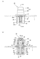
以下、図1〜7を参照して、本発明に係る緩衝装置の一実施形態について説明する。 Hereinafter, an embodiment of a shock absorber according to the present invention will be described with reference to FIGS.
図1、図5及び図7に示すように、この実施形態の緩衝装置10は、固定部材1と該固定部材1に対して近接離反するように移動する移動体5との間に配置されて、移動体5が当接して、その動きを緩衝するものである。固定部材1としては、例えば、車両のグローブボックスや、車両フレーム、車両パネル等が挙げられ、移動体5としては、グローブボックスの開口部に対して開閉するリッドや、車両の各種ドア(サイドドアやハッチバックドアなど)等が挙げられるが、特に限定はされない。また、前記固定部材1には、丸孔状の取付孔3が形成されている(図1参照)。 As shown in FIGS. 1, 5, and 7, the shock absorber 10 according to this embodiment is disposed between the fixed
図1に示すように、この実施形態の緩衝装置10は、固定部材1に取付けられるケース部材20と、該ケース部材20にスライド可能に装着されると共に、移動体5に当接してその衝撃を受ける緩衝部材30と、該緩衝部材30を、ケース部材20から離反する方向(ここでは移動体5側)に向けて付勢するバネ60とを備えている。 As shown in FIG. 1, a shock absorber 10 of this embodiment is mounted on a
なお、この実施形態においては、固定部材1の取付孔3に、ケース部材20が取付けられ、それによって固定部材1に緩衝装置10が取付けられるようになっているが、リッドやドア等の移動体5に取付孔を設けて、該移動体5側に緩衝装置10を取付けてもよく、固定部材と移動体との間に緩衝装置10が配設されるようになっていれば、特に限定はされない。 In this embodiment, the
図1、図5(b)及び図6(b)に示すように、前記ケース部材20は、底部21と、バネ60の一端を支持する支持部と、底部21から突出する軸部23と、該軸部23の外周に配置されて、緩衝部材30を受け入れる周壁25とを有している。 As shown in FIG. 1, FIG. 5B and FIG. 6B, the
この実施形態のケース部材20は、全体として有底の略円筒状をなしており、略円板状の底部21を有しており、該底部21にバネ60の一端を支持されるようになっている。すなわち、この実施形態では、底部21が、本発明における「支持部」をなしている。なお、周壁25の内周に、底部21から所定間隔をあけて、環状突起や円弧状リブ等を設けるなどして、底部21とは別に、バネ60の支持部を設けてもよい。 The
また、底部21の内面(バネ60の支持面)側であって、その中央からは軸部23が所定高さで突出しており、該軸部23がバネ60の内部に挿入されるようになっている(図5(b)参照)。更に、軸部23の外周であって、前記底部21の周縁からは、略円筒状をなした周壁25が、軸部23と同じ方向に所定長さで立設されており、この周壁25の内周に、緩衝部材30やバネ60が受け入れられるようになっている。 Further, on the inner surface (support surface of the spring 60) side of the
また、図1及び図5(b)に示すように、前記軸部23の軸方向の先端部(底部21から離れた端部)には、他の部分よりも拡径した略円形突部状をなした拡径部24が設けられている。なお、この拡径部24の周方向対向位置には、互いに平行とされた平坦面24a,24aが形成されている(図1参照)。また、図5(b)及び図6(b)に示すように、軸部23の軸方向の先端部は、前記周壁25の立設方向の先端部よりも、やや長く突出している。 Moreover, as shown in FIG.1 and FIG.5 (b), at the front-end | tip part (end part distant from the bottom part 21) of the axial direction of the said
更に、周壁25の、周方向に対向する箇所には、ケース部材20の軸方向に沿って、すなわち、軸部23の軸方向に沿って、所定長さで切欠き部25a,25aが形成されている(図1及び図6(b)参照)。また、周壁25の立設方向の先端部外周からは、固定部材1の取付孔3の表側周縁に当接する、環状のフランジ部27が外径方向に向けて突設されている。更に、周壁25の外周であって、前記切欠き部25a,25aに対して周方向に直交する位置からは、前記固定部材1の取付孔3の裏側周縁に係止する、係止部29,29が突設されている(図5(b)及び図6(a)参照)。なお、係止部29は、周壁25の外径方向に向けて高く突出した頂部29aを有しており(図5(b)参照)、この頂部29aより底部21側は緩やかに縮径するテーパ状をなし、頂部29aよりフランジ部27側は、急傾斜をなして縮径するテーパ状をなしている。 Furthermore,
また、この実施形態においては、図5(b)に示すように、軸部23の拡径部24の、基端側の段部24bが、周壁25の外周に突設された係止部29の頂部29aと、フランジ部27との間に、配置されるようになっている。 Further, in this embodiment, as shown in FIG. 5B, the locking
なお、上記ケース部材は、この実施形態の場合、有底の略円筒状をなしているが、例えば、有底の角筒状をなしていてもよく、固定部材又は移動体に取付け可能で、かつ、緩衝部材をスライド可能に支持可能な構造であれば、特に限定はされない。 In the case of this embodiment, the case member has a bottomed substantially cylindrical shape, but may have, for example, a bottomed rectangular tube shape, and can be attached to a fixed member or a moving body. And if it is a structure which can support a buffer member so that a slide is possible, it will not specifically limit.
次に、ケース部材20にスライド可能に装着される緩衝部材30について説明する。緩衝部材30は、ケース部材20に装着されて、ケース部材20の底部21に対して近接又は離反するように、ケース部材20の軸方向に沿ってスライドする。 Next, the
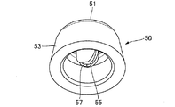
図1、図5(a)及び図6(b)に示すように、この緩衝部材30は、ケース部材20の軸部23が挿入される内筒41と、該内筒41の外周に配置される外筒43と、バネ60の他端を支持するバネ受部43aとを有している。また、この実施形態における緩衝部材30は、内筒41及び外筒43を有する本体40と、該本体40の先端部外周に装着される弾性材からなるキャップ50とを有している。 As shown in FIGS. 1, 5 (a) and 6 (b), the
まず、本体40について詳述する。図5(b)及び図6(b)に示すように、前記本体40は、ケース部材20の軸部23が挿入される略円筒状の内筒41と、該内筒41の外周に同心状に配置された略円筒状の外筒43とを有する二重筒状をなしており、内筒41及び外筒43の間には、バネ60の他端が挿入されて支持される、筒状空間45が形成されている。 First, the
図1に示すように、内筒41の、軸方向の先端部側の外周には、複数の環状突部49が突設されている。更に、図3に示すように、内筒41の軸方向の基端部側には、軸方向に沿って伸びる複数のスリット46が周方向に複数形成されており、これらの複数のスリット46を介して、撓み可能とされた係合爪47が複数個分割して形成されている(ここでは4個)。各係合爪47は、その先端部47aが内筒41の内径方向に突出した形状をなしている。また、各係合爪47の先端部47aの外面(ケース部材20側の面)には、内径方向に向かって先端部47aを次第に肉薄とするテーパ面47bが設けられており(図3及び図5(b)参照)、複数の係合爪47内に軸部23を挿入する際のガイドをなしている。 As shown in FIG. 1, a plurality of
一方、図1及び図5(b)に示すように、内筒41の軸方向途中の外周から、環状のバネ受部43aが突設されており、該バネ受部43aを介して、外筒43が、内筒41の係合爪47を含めた部分よりもやや短くなるように、内筒41に対して同心状をなすように延設されており、この外筒43と前記内筒41との間に前記筒状空間45が画成されるようになっている。 On the other hand, as shown in FIGS. 1 and 5 (b), an annular
上記緩衝部材30は、ケース部材20の底部21に一端を支持されたバネ60の他端が、前記筒状空間45内に挿入された状態で、ケース部材20の底部21に対して近接する方向に押し込むと、バネ60の他端が、筒状空間45の軸方向外方の端部、すなわち、前記バネ受部43aに当接して支持されると共に、内筒41の複数の係合爪47の先端部47aが、軸部23の拡径部24に係合するため、バネ60の付勢力に抗して、ケース部材20に対して抜け止めがなされる(図5(b)及び図6(b)参照)。すなわち、この実施形態では、係合爪47及び軸部23の拡径部24が、本発明における「抜け止め手段」をなしている。 The
なお、この抜け止め手段としては、上記構造に限定されるものではなく、その設置箇所も特に限定はない。すなわち、ケース部材と緩衝部材との間であって、緩衝部材をケース部材から抜け止め可能であれば、どのような構造でもよい。なお、抜け止め手段の他構造については、後述する図8や図9の実施形態において説明する。 The retaining means is not limited to the above structure, and the installation location is not particularly limited. In other words, any structure may be used as long as it is between the case member and the buffer member and can prevent the buffer member from being detached from the case member. The other structure of the retaining means will be described in the embodiments shown in FIGS.
そして、図5(b)及び図6(b)に示すように、この緩衝装置10においては、ケース部材20の周壁25の内周に、緩衝部材30の外筒43の外周が配置されて、緩衝部材30のスライド時の第1ガイドG1をなすと共に、ケース部材20の軸部23の外周に、緩衝部材30の内筒41の内周が配置されて、緩衝部材30のスライド時の第2ガイドG2をなすように構成されている。 5 (b) and FIG. 6 (b), in this
この実施形態では、図5(b)及び図6(b)に示すように、外筒43の外径は、ケース部材20の周壁25の内径にほぼ適合した寸法に形成され、ケース部材20の底部21に対して緩衝部材30が近接離反する方向にスライドするときに、周壁25の内周に外筒43の外周が摺接して、前記第1ガイドG1をなしている。また、図6(b)に示すように、内筒41の内径は、ケース部材20の軸部23の拡径部24の外径にほぼ適合した寸法に形成されており、ケース部材20の底部21に対して緩衝部材30が近接離反する方向にスライドするときに、ケース部材20の軸部23の外周に内筒41の内周が摺接して、前記第2ガイドG2をなしている。 In this embodiment, as shown in FIG. 5B and FIG. 6B, the outer diameter of the
なお、本発明において、緩衝部材のスライド時のガイドとは、緩衝部材のスライド時に、緩衝部材がケース部材の軸心に対して所定角度傾いたときに、ケース部材の周壁内周や、ケース部材の軸部外周に当接して、緩衝部材のそれ以上の傾きを規制しつつスライドさせることを意味している。したがって、上記のように、周壁25の内周に外筒43の外周を摺接させたり、軸部23の外周に内筒41の内周が摺接させたりしなくても、周壁25の内周と外筒43の外周との間や、軸部23の外周と内筒41の内周との間に、所定の隙間が形成されていてもよい。 In the present invention, the guide at the time of sliding of the buffer member is the inner periphery of the peripheral wall of the case member or the case member when the buffer member is inclined at a predetermined angle with respect to the axis of the case member at the time of sliding of the buffer member. It is meant to slide while restricting the further inclination of the buffer member. Therefore, as described above, even if the outer periphery of the
更に、この実施形態においては、図5(b)及び図6(b)に示すように、ケース部材20を軸方向に沿った断面で見たときに、前記第1ガイドG1及び前記第2ガイドG2が軸方向に重なる位置となるように配置されている。 Furthermore, in this embodiment, as shown in FIGS. 5B and 6B, when the
また、図5(b)及び図6(b)に示すように、緩衝部材30がケース部材20の底部21から離れる方向にスライドして、抜け止め手段(ここでは係合爪47及び軸部23の拡径部24)により、ケース部材20に対して緩衝部材30が抜け止めされた状態で、緩衝部材30の筒状空間45は、ケース部材20の軸方向外方に配置されており、該筒状空間45の軸方向外方の端部がバネ受部45aをなすように構成されている。 Further, as shown in FIGS. 5B and 6B, the
一方、図2及び図5(b)に示すように、上記本体40に装着されるキャップ50は、ゴムや弾性エラストマー等の弾性材からなり、移動体5に当接する略円板状の当接部51と、該当接部51の周縁から次第に拡径するように延設した周壁53とを有している。前記周壁53の内周には、複数の環状凹部53aが形成されており、これに前記内筒41の環状突部49に係合して、本体40にキャップ50が装着されるようになっている(図5(b)及び図6(b)参照)。 On the other hand, as shown in FIGS. 2 and 5B, the
また、キャップ50の当接部51の内面側(本体40側)からは、本体40の内筒41内に突出する突部55が突設されており、軸部23の軸方向先端の拡径部24に、撓み変形しつつ弾性的に当接するようになっている(図7参照)。なお、図2に示すように、この実施形態の突部55は、軸方向に伸びるスリット57によって複数に分割された形状をなしており(ここでは2分割)、緩衝部材30が押し込まれて軸部23の拡径部24に当接したときに、押し潰されるように弾性変形するようになっている(図7参照)。 Further, a projecting
なお、この実施形態においては、緩衝部材30は、本体40とキャップ50との2部品構造となっているが、ゴム等で形成された1部品構造としてもよく、内筒、外筒及び筒状空間を有し、バネ60の他端を支持可能な構造であれば、特に限定はされない。 In this embodiment, the
次に、上記構造からなる緩衝装置10の使用方法及び作用効果について説明する。 Next, the usage method and effect of the
この緩衝装置10は、例えば、次のようにして組み立てることができる。 This
まず、緩衝部材30の本体40の軸方向先端側にキャップ50を被せて、その環状凹部53aを環状突部49に係合させることによって、内筒41内に突部55が突出配置された状態で、本体40にキャップ50が装着されて、緩衝部材30を得ることができる。 First, the
次いで、ケース部材20の周壁25内にバネ60を収容配置して、バネ60内に軸部23を挿入すると共に、バネ60の一端を底部21に当接させて支持させる。この状態では、バネ60の他端が、ケース部材20の軸方向の先端側開口部から、所定長さ突出した状態となっている。 Next, the
そして、緩衝部材30の複数の係合爪47の内径方向中心に、ケース部材20の軸部23を整合させると共に、緩衝部材30の筒状空間45にバネ60の他端を整合させて配置して、ケース部材20に対して緩衝部材30を押し込んでいく。すると、先端部47aが、軸部23の拡径部24に押圧されて、複数の係合爪47が押し広げられて、内筒41内に軸部23の拡径部24が徐々に挿入されると共に、バネ60の他端が筒状空間45内に挿入されていく。その後、係合爪47の先端部47aが、軸部23の拡径部24を乗り越えると、各係合爪47が弾性復帰して、その先端部47aが軸部23の拡径部24の段部24bに係合すると共に、内筒41内に軸部23が挿入され、かつ、筒状空間45内に挿入されたバネ60の他端が、筒状空間45の軸方向外方のバネ受部43aに当接して支持される。その結果、バネ60が圧縮された状態で、ケース部材20と緩衝部材30との間に介装されると共に、ケース部材20に緩衝部材30が抜け止めされた状態で、スライド可能に装着することができる(図5(b)及び図6(b)参照)。また、この状態では、バネ60によって緩衝部材30が移動体5側に向けて付勢されて、緩衝部材30がケース部材20の底部21から離れる方向にスライドした状態となっている(図5(b)及び図6(b)参照)。 The
上記のように組立てた緩衝装置10のケース部材20を、固定部材1の取付孔3の表側から挿入して押し込むことによって、図5(b)及び図6(a)に示すように、取付孔3の表側周縁にフランジ部27が当接すると共に、取付孔3の裏側周縁に係止部29が係止して、固定部材1に緩衝装置10を取付けることができる。 By inserting and pushing the
上記状態で、図7に示すように、固定部材1に対して移動体5が近接する方向に移動(例えば、グローブボックスの開口部に対してリッドが閉じる方向に移動)して、移動体5が緩衝部材30のキャップ50の当接部51に衝突して、緩衝部材30が押圧されると、バネ60の付勢力に抗して同バネ60を圧縮させつつ、緩衝部材30がケース部材20の底部21に近接する方向にスライドするので、このバネ60の弾性付勢力によって、移動体5の衝撃力を吸収して緩衝することができる。また、移動体5がバネ60の弾性力を受け止めた状態(例えば、グローブボックスのリッドが閉じた状態)で、移動体5が振動しても、その振動を吸収して緩衝することができる。なお、図7に示すように、キャップ50の突部55が、軸部23の拡径部24に弾性的に当接して弾性変形するようになっている。 In the above state, as shown in FIG. 7, the moving
そして、図5(b)及び図6(b)に示すように、この緩衝装置10においては、ケース部材20の周壁25の内周に、緩衝部材30の外筒43の外周が配置されて、緩衝部材30のスライド時の第1ガイドG1をなすと共に、ケース部材20の軸部23の外周に、緩衝部材30の内筒41の内周が配置されて、緩衝部材30のスライド時の第2ガイドG2をなしているため、2つのガイドG1,G2で緩衝部材30をスライドガイドすることができる。その結果、ケース部材20の底部21に対して緩衝部材30が近接離反する方向にスライドするときに、緩衝部材30を傾きにくくして、円滑にスライドさせることができる(図5(b)及び図6(b)参照)。 5 (b) and FIG. 6 (b), in this
また、この緩衝装置10においては、ケース部材20の周壁25の外周及び緩衝部材30の外筒43の外周に、第1ガイドG1を設け、ケース部材20の軸部23の外周及び緩衝部材30の内筒41の内周に、第2ガイドG2を設けたので、緩衝部材30が、ケース部材20の底部21に近接する方向にスライドしても、ケース部材20の底部21の外面(バネ支持面とは反対面)から、緩衝部材30の軸部23が突出しない構造とすることができ、その結果、緩衝装置10の全体の軸方向長さを短くすることができ、緩衝装置10の取付スペースを小さくすることができる。 Further, in the
また、この実施形態においては、図5(b)及び図6(b)に示すように、ケース部材20を軸方向に沿った断面で見たときに、前記第1ガイドG1及び前記第2ガイドG2が軸方向に重なる位置となるように配置されているので、バネ60の内周及び外周の位置において、緩衝部材30のスライドをガイドすることができ、緩衝装置10を軸方向に、より短くコンパクトにすることができると共に、緩衝部材30のスライド量を更に大きく確保することができる。 In this embodiment, as shown in FIGS. 5B and 6B, when the
更に、この実施形態においては、図5(b)及び図6(b)に示すように、緩衝部材30がケース部材20の底部21から離れる方向にスライドし、抜け止め手段(ここでは係合爪47及び軸部23の拡径部24)により、ケース部材20に対して緩衝部材30が抜け止めされた状態で、緩衝部材30の筒状空間45は、ケース部材20の軸方向外方に配置されるように構成されているので、上述したように、緩衝装置10を組立てる際に、ケース部材20の軸部23にバネ60を配置して、その一端を底部21により支持させた状態で、バネ60の他端を緩衝部材30の筒状空間45に挿入しやすくなり、組立作業性を向上させることができる。また、バネ60の長さを十分に確保することができ、移動体5の緩衝をより効果的に図ることができる。 Furthermore, in this embodiment, as shown in FIG. 5B and FIG. 6B, the
また、この実施形態においては、抜け止め手段として、ケース部材20の軸部23の先端部に設けた拡径部24と、緩衝部材30の内筒41の基端部側に、スリット46を介して撓み可能とされた係合爪47とから構成した。そのため、ケース部材20にバネ60を配置した後、緩衝部材30の内筒41にケース部材20の軸部23を整合させて、ケース部材20に対して緩衝部材30を押し込むだけの簡単な作業で、撓み可能な係合爪47の先端部47aが軸部23の拡径部24の段部24bに係合して、ケース部材20に対して緩衝部材30を抜け止めすることができ(図6(b)参照)、組立作業性をより向上させることができる。また、軸部23の先端の拡径部24と、内筒41の先端側に設けた係合爪47とから抜け止め手段が構成され、バネ60の内径側に抜け止め構造が配置されているので(図6(b)参照)、バネ60の外径を比較的大きく確保することができ、バネ60の弾性付勢力を調整しやすくすることができる。 Further, in this embodiment, as the retaining means, the
また、この実施形態においては、図7に示すように、緩衝部材30が移動体5に押圧されて、バネ60の付勢力に抗して、緩衝部材30がケース部材20の底部21に近接する方向にスライドする際、緩衝部材30の外筒43が、ケース部材20の底部21に当接する前に、キャップ50の突部55が、軸部23の軸方向先端の拡径部24に弾性的に当接して、スリット57を介して押し潰されて広がるように弾性変形するようになっている。なお、図7においては、便宜上、緩衝部材30が移動体5によって最大限押されて、内筒41の基端部がケース部材20の底部21に当接した状態が示されている。そして、この実施形態では、緩衝部材30が移動体5に押圧され、バネ60の弾性付勢力に抗して緩衝部材30がケース部材20の底部21に当接する前に、キャップ50の突部55が軸部23の先端に弾性的に当接するので、移動体5が緩衝部材30に衝突した際の、打音を緩和することができる。 Further, in this embodiment, as shown in FIG. 7, the
図8には、本発明に係る緩衝装置の、他の実施形態が示されている。なお、前記実施形態と実質的に同一部分には同符号を付してその説明を省略する。 FIG. 8 shows another embodiment of the shock absorber according to the present invention. Note that substantially the same parts as those of the above-described embodiment are denoted by the same reference numerals, and description thereof is omitted.
この実施形態の緩衝装置10Aは、前記実施形態と抜け止め手段の構造が異なっている。 The
すなわち、図8(b)に示すように、ケース部材20Aの軸部23の軸方向先端部に、軸方向に沿ってスリット26が形成されており、該スリット26を介して、拡径部24が二股状をなすように二分割されて撓み可能な構造となっている。一方、緩衝部材30Aの本体40の内筒41には、その軸方向基端部の内周に、前記拡径部24に係合する係合突部42が突設されている。 That is, as shown in FIG. 8B, a
したがって、ケース部材20Aにバネ60を配置した後、緩衝部材30Aの内筒41にケース部材20Aの軸部23を整合させて、ケース部材20に対して緩衝部材30Aを押し込むと、内筒41の係合突部42によって、軸部23の拡径部24が押圧されて内方に撓み、係合突部42が拡径部24を通り越えると、拡径部24が弾性復帰して、その段部24bに係合突部42が係合して、ケース部材20Aに対して緩衝部材30Aを抜け止めした状態で装着することができる(図8(b)参照)。 Therefore, after the
図9には、本発明に係る緩衝装置の、更に他の実施形態が示されている。なお、前記実施形態と実質的に同一部分には同符号を付してその説明を省略する。 FIG. 9 shows still another embodiment of the shock absorber according to the present invention. Note that substantially the same parts as those of the above-described embodiment are denoted by the same reference numerals, and description thereof is omitted.
この実施形態の緩衝装置10Bは、前記実施形態と抜け止め手段の構造が異なっている。 The
すなわち、図9(b)に示すように、ケース部材20Bの軸部23は、その先端部に拡径部のない柱状をなしており、この軸部23が、緩衝部材30Bの、内径側に突起のない内筒41にスライド可能に挿入されるようになっている。また、図9(b)に示すように、緩衝部材30Bの外筒43の他端部には、軸方向に沿って伸びるスリット44aが、周方向に複数形成されており、該スリット44aを介して外筒43の他端部側が撓み可能となっている。更に外筒43の他端部外周であって、周方向に対向する箇所から、係合突部44,44がそれぞれ突設されており、これらの係合突部44,44が、ケース部材20Bの切欠き部25a,25aのフランジ部27側の周縁部に係合するようになっている。 That is, as shown in FIG. 9B, the
したがって、ケース部材20Bにバネ60を配置した後、緩衝部材30Bの内筒41にケース部材20Bの軸部23を整合させて、ケース部材20に対して緩衝部材30Bを押し込むと、内筒41内に軸部23が挿入されると共に、ケース部材20Bの周壁25内周に、係合突部44が押圧されて、外筒43が内方に撓み、係合突部44が切欠き部25aに至ると、外筒43が弾性復帰して、係合突部44,44が切欠き部25a,25aのフランジ部27側の周縁部にそれぞれ係合して、ケース部材20Bに対して緩衝部材30Bを抜け止めした状態で装着することができる(図9(b)参照)。 Therefore, after the
図10及び図11には、本発明に係る緩衝装置の、更に他の実施形態が示されている。なお、前記実施形態と実質的に同一部分には同符号を付してその説明を省略する。 10 and 11 show still another embodiment of the shock absorber according to the present invention. Note that substantially the same parts as those of the above-described embodiment are denoted by the same reference numerals, and description thereof is omitted.
この実施形態の緩衝装置10Cは、前記実施形態と緩衝部材の構造が異なっている。すなわち、この実施形態の緩衝部材30Cは、キャップ50の当接部51の内面側から、本体40の内筒41内に突出する突部55Cの形状が異なっている。この突部55Cは、当接部51の中央部外面が凹む一方、同当接部51の中央部内面から、頂部が緩やかな曲面状とされた略山型状をなすように、かつ、前記実施形態の突部55よりも低く突出した形状となっている。 The
そして、常時は、バネ60の付勢力によって、緩衝部材30Cがケース部材20の底部21から離れる方向にスライドした状態とされる(図10参照)。この状態で、緩衝部材30Cが移動体5に押圧されて、バネ60の付勢力に抗して、緩衝部材30Cがケース部材20の底部21に近接する方向にスライドする際には、緩衝部材30Cの内筒41や外筒43が、ケース部材20の底部21に当接する前に、前記突部55Cが、軸部23の軸方向先端の拡径部24に弾性的に当接する(図11(a)参照)。更に緩衝部材30Cが移動体5に押されると、内筒41の基端部側の係合爪47がケース部材20の底部21に当接して、移動体5のそれ以上の移動が規制されると共に、突部55Cが軸部23の軸方向先端に押圧されて、当接部51の中央部内面がほぼ平らに、かつ、同当接部51の中央部外面側の凹みがほぼ埋まるように、突部55Cが弾性変形する(図11(b)参照)。この実施形態においても、前記実施形態と同様に、バネ60の弾性付勢力に抗して緩衝部材30Cがケース部材20の底部21に当接する前に、キャップ50の突部55Cが軸部23の先端に弾性的に当接するので、移動体5が緩衝部材30に衝突した際の、打音を緩和することができる。 Then, the
なお、本発明は、上述した実施形態に限定されるものではなく、本発明の要旨の範囲内で、各種の変形実施形態が可能であり、そのような実施形態も本発明の範囲に含まれる。 It should be noted that the present invention is not limited to the above-described embodiment, and various modified embodiments are possible within the scope of the present invention, and such an embodiment is also included in the scope of the present invention. .
1 固定部材
3 取付孔
5 移動体
10,10A,10B,10C 緩衝装置
20,20A,20B ケース部材
21 底部
23 軸部
24 拡径部
25 周壁
29 係止部
30,30A,30B,30C 緩衝部材
40 本体
41 内筒
43 外筒
43a バネ受部
45 筒状空間
47 係合爪
50 キャップ
55,55C 突部
60 バネ
G1 第1ガイド
G2 第2ガイドDESCRIPTION OF
Claims (6)
ケース部材と、該ケース部材にスライド可能に装着されると共に、前記移動体又は前記固定部材に当接して衝撃を受ける緩衝部材と、該緩衝部材を前記ケース部材から離反する方向に向けて付勢するバネとを備え、
前記ケース部材は、底部と、前記バネの一端を支持する支持部と、前記底部から突出する軸部と、該軸部外周に配置されて前記緩衝部材を受け入れる周壁とを有し、
前記緩衝部材は、前記ケース部材の軸部が挿入される内筒と、該内筒の外周に配置される外筒と、前記バネの他端を支持するバネ受部とを有し、
前記ケース部材と前記緩衝部材との間には、前記緩衝部材を前記ケース部材から抜け止めする抜け止め手段が設けられ、
前記ケース部材の周壁の内周に、前記緩衝部材の外筒の外周が配置されて、前記緩衝部材のスライド時の第1ガイドをなすと共に、前記ケース部材の軸部の外周に、前記緩衝部材の内筒の内周が配置されて、前記緩衝部材のスライド時の第2ガイドをなしており、
前記緩衝部材は、前記内筒及び前記外筒を有する本体と、該本体の先端部外周に装着される弾性材からなるキャップとを有し、
前記内筒への前記軸部の挿入方向において、前記内筒は、前記外筒よりも突出した形状をなしており、前記キャップは、前記本体に装着された状態で、前記内筒の突出側端面の開口を覆い、かつ、該開口の周縁に支持される板状をなした、当接部を有していることを特徴とする緩衝装置。A shock absorber disposed between a fixed member and a moving body that moves so as to approach and separate from the fixed member, and cushions the movement of the moving body,
A case member, a shock-absorbing member that is slidably attached to the case member, receives an impact by contacting the moving body or the fixed member, and biases the shock-absorbing member in a direction away from the case member And a spring to
The case member includes a bottom portion, a support portion that supports one end of the spring, a shaft portion that protrudes from the bottom portion, and a peripheral wall that is disposed on the outer periphery of the shaft portion and receives the buffer member,
The buffer member includes an inner cylinder into which the shaft portion of the case member is inserted, an outer cylinder disposed on the outer periphery of the inner cylinder, and a spring receiving portion that supports the other end of the spring,
Between the case member and the buffer member, a retaining means for retaining the buffer member from the case member is provided,
The outer periphery of the outer cylinder of the buffer member is disposed on the inner periphery of the peripheral wall of the case member to form a first guide when the buffer member slides, and the buffer member on the outer periphery of the shaft portion of the case member The inner circumference of the inner cylinder is arranged to form a second guide when the buffer member slides,
The buffer member has a main body having the inner cylinder and the outer cylinder, and a cap made of an elastic material attached to the outer periphery of the distal end portion of the main body,
In the insertion direction of the shaft portion into the inner cylinder, the inner cylinder has a shape protruding from the outer cylinder, and the cap is mounted on the main body, and the protruding side of the inner cylinder A shock absorber comprising an abutting portion which covers an opening of an end face and has a plate shape supported by the periphery of the opening.
前記緩衝部材が前記ケース部材の支持部から離れる方向にスライドして、前記抜け止め手段により前記ケース部材に対して前記緩衝部材が抜け止めされた状態で、前記筒状空間は、前記ケース部材の軸方向外方に配置されており、該筒状空間の軸方向外方の端部が、前記バネ受部をなすように構成されている請求項1又は2記載の緩衝装置。A cylindrical space is formed between the inner cylinder and the outer cylinder of the buffer member,
In the state where the buffer member slides in a direction away from the support portion of the case member and the buffer member is prevented from being detached from the case member by the retaining means, the cylindrical space is The shock absorber according to claim 1 or 2, wherein the shock absorber is disposed outward in the axial direction, and an axially outward end of the cylindrical space is configured to form the spring receiving portion.
ケース部材と、該ケース部材にスライド可能に装着されると共に、前記移動体又は前記固定部材に当接して衝撃を受ける緩衝部材と、該緩衝部材を前記ケース部材から離反する方向に向けて付勢するバネとを備え、
前記ケース部材は、底部と、前記バネの一端を支持する支持部と、前記底部から突出する軸部と、該軸部外周に配置されて前記緩衝部材を受け入れる周壁とを有し、
前記緩衝部材は、前記ケース部材の軸部が挿入される内筒と、該内筒の外周に配置される外筒と、前記バネの他端を支持するバネ受部とを有し、
前記ケース部材と前記緩衝部材との間には、前記緩衝部材を前記ケース部材から抜け止めする抜け止め手段が設けられ、
前記ケース部材の周壁の内周に、前記緩衝部材の外筒の外周が配置されて、前記緩衝部材のスライド時の第1ガイドをなすと共に、前記ケース部材の軸部の外周に、前記緩衝部材の内筒の内周が配置されて、前記緩衝部材のスライド時の第2ガイドをなしており、
前記抜け止め手段は、前記ケース部材の軸部の先端部に拡径して設けられた拡径部と、前記緩衝部材の内筒の基端部側に、スリットを介して撓み可能に形成され、前記拡径部に係合可能とされた係合爪とからなることを特徴とする緩衝装置。A shock absorber disposed between a fixed member and a moving body that moves so as to approach and separate from the fixed member, and cushions the movement of the moving body,
A case member, a shock-absorbing member that is slidably attached to the case member, receives an impact by contacting the moving body or the fixed member, and biases the shock-absorbing member in a direction away from the case member And a spring to
The case member includes a bottom portion, a support portion that supports one end of the spring, a shaft portion that protrudes from the bottom portion, and a peripheral wall that is disposed on the outer periphery of the shaft portion and receives the buffer member,
The buffer member includes an inner cylinder into which the shaft portion of the case member is inserted, an outer cylinder disposed on the outer periphery of the inner cylinder, and a spring receiving portion that supports the other end of the spring,
Between the case member and the buffer member, a retaining means for retaining the buffer member from the case member is provided,
The outer periphery of the outer cylinder of the buffer member is disposed on the inner periphery of the peripheral wall of the case member to form a first guide when the buffer member slides, and the buffer member on the outer periphery of the shaft portion of the case member The inner circumference of the inner cylinder is arranged to form a second guide when the buffer member slides,
The retaining means is formed in a diameter-enlarged portion provided at the distal end portion of the shaft portion of the case member and a proximal end portion side of the inner cylinder of the buffer member so as to be able to bend through a slit. A shock absorber comprising: an engaging claw capable of engaging with the enlarged diameter portion.
ケース部材と、該ケース部材にスライド可能に装着されると共に、前記移動体又は前記固定部材に当接して衝撃を受ける緩衝部材と、該緩衝部材を前記ケース部材から離反する方向に向けて付勢するバネとを備え、
前記ケース部材は、底部と、前記バネの一端を支持する支持部と、前記底部から突出する軸部と、該軸部外周に配置されて前記緩衝部材を受け入れる周壁とを有し、
前記緩衝部材は、前記ケース部材の軸部が挿入される内筒と、該内筒の外周に配置される外筒と、前記バネの他端を支持するバネ受部とを有し、
前記ケース部材と前記緩衝部材との間には、前記緩衝部材を前記ケース部材から抜け止めする抜け止め手段が設けられ、
前記ケース部材の周壁の内周に、前記緩衝部材の外筒の外周が配置されて、前記緩衝部材のスライド時の第1ガイドをなすと共に、前記ケース部材の軸部の外周に、前記緩衝部材の内筒の内周が配置されて、前記緩衝部材のスライド時の第2ガイドをなしており、
前記緩衝部材は、前記内筒及び前記外筒を有する本体と、該本体の先端部外周に装着される弾性材からなるキャップとを有し、
該キャップの内面側からは、前記内筒内に突出する突部が設けられており、
前記緩衝部材が押圧されて、前記バネの弾性付勢力に抗してスライドし、前記緩衝部材が前記ケース部材の底部に当接する前に、前記キャップの突部が前記ケース部材の軸部の先端部に当接するように構成されていることを特徴とする緩衝装置。A shock absorber disposed between a fixed member and a moving body that moves so as to approach and separate from the fixed member, and cushions the movement of the moving body,
A case member, a shock-absorbing member that is slidably attached to the case member, receives an impact by contacting the moving body or the fixed member, and biases the shock-absorbing member in a direction away from the case member And a spring to
The case member includes a bottom portion, a support portion that supports one end of the spring, a shaft portion that protrudes from the bottom portion, and a peripheral wall that is disposed on the outer periphery of the shaft portion and receives the buffer member,
The buffer member includes an inner cylinder into which the shaft portion of the case member is inserted, an outer cylinder disposed on the outer periphery of the inner cylinder, and a spring receiving portion that supports the other end of the spring,
Between the case member and the buffer member, a retaining means for retaining the buffer member from the case member is provided,
The outer periphery of the outer cylinder of the buffer member is disposed on the inner periphery of the peripheral wall of the case member to form a first guide when the buffer member slides, and the buffer member on the outer periphery of the shaft portion of the case member The inner circumference of the inner cylinder is arranged to form a second guide when the buffer member slides,
The buffer member has a main body having the inner cylinder and the outer cylinder, and a cap made of an elastic material attached to the outer periphery of the distal end portion of the main body,
From the inner surface side of the cap, a protrusion protruding into the inner cylinder is provided,
Before the shock-absorbing member is pressed and slides against the elastic biasing force of the spring, and the shock-absorbing member comes into contact with the bottom of the case member, the protrusion of the cap is the tip of the shaft portion of the case member. A shock absorber configured to abut against the portion.
ケース部材と、該ケース部材にスライド可能に装着されると共に、前記移動体又は前記固定部材に当接して衝撃を受ける緩衝部材と、該緩衝部材を前記ケース部材から離反する方向に向けて付勢するバネとを備え、
前記ケース部材は、底部と、前記バネの一端を支持する支持部と、前記底部から突出する軸部と、該軸部外周に配置されて前記緩衝部材を受け入れる周壁とを有し、
前記緩衝部材は、前記ケース部材の軸部が挿入される内筒と、該内筒の外周に配置される外筒と、前記バネの他端を支持するバネ受部とを有し、
前記ケース部材と前記緩衝部材との間には、前記緩衝部材を前記ケース部材から抜け止めする抜け止め手段が設けられ、
前記ケース部材の周壁の内周に、前記緩衝部材の外筒の外周が配置されて、前記緩衝部材のスライド時の第1ガイドをなすと共に、前記ケース部材の軸部の外周に、前記緩衝部材の内筒の内周が配置されて、前記緩衝部材のスライド時の第2ガイドをなしており、
前記緩衝部材は、前記内筒の軸方向途中の外周から、前記バネ受部が突設されており、該バネ受部を介して、前記外筒が、前記内筒よりも短くなるように延設されていることを特徴とする緩衝装置。A shock absorber disposed between a fixed member and a moving body that moves so as to approach and separate from the fixed member, and cushions the movement of the moving body,
A case member, a shock-absorbing member that is slidably attached to the case member, receives an impact by contacting the moving body or the fixed member, and biases the shock-absorbing member in a direction away from the case member And a spring to
The case member includes a bottom portion, a support portion that supports one end of the spring, a shaft portion that protrudes from the bottom portion, and a peripheral wall that is disposed on the outer periphery of the shaft portion and receives the buffer member,
The buffer member includes an inner cylinder into which the shaft portion of the case member is inserted, an outer cylinder disposed on the outer periphery of the inner cylinder, and a spring receiving portion that supports the other end of the spring,
Between the case member and the buffer member, a retaining means for retaining the buffer member from the case member is provided,
The outer periphery of the outer cylinder of the buffer member is disposed on the inner periphery of the peripheral wall of the case member to form a first guide when the buffer member slides, and the buffer member on the outer periphery of the shaft portion of the case member The inner circumference of the inner cylinder is arranged to form a second guide when the buffer member slides,
The buffer member has the spring receiving portion protruding from the outer periphery in the axial direction of the inner cylinder, and the outer cylinder extends through the spring receiving portion so as to be shorter than the inner cylinder. A shock absorber characterized by being provided.
Applications Claiming Priority (3)
| Application Number | Priority Date | Filing Date | Title |
|---|---|---|---|
| JP2015098180 | 2015-05-13 | ||
| JP2015098180 | 2015-05-13 | ||
| PCT/JP2016/064005 WO2016181994A1 (en) | 2015-05-13 | 2016-05-11 | Shock-absorbing device |
Publications (2)
| Publication Number | Publication Date |
|---|---|
| JPWO2016181994A1 JPWO2016181994A1 (en) | 2018-06-14 |
| JP6400192B2 true JP6400192B2 (en) | 2018-10-03 |
Family
ID=57248166
Family Applications (1)
| Application Number | Title | Priority Date | Filing Date |
|---|---|---|---|
| JP2017517965A Active JP6400192B2 (en) | 2015-05-13 | 2016-05-11 | Shock absorber |
Country Status (5)
| Country | Link |
|---|---|
| US (1) | US10451131B2 (en) |
| JP (1) | JP6400192B2 (en) |
| CN (1) | CN107614922B (en) |
| GB (2) | GB2553729B (en) |
| WO (1) | WO2016181994A1 (en) |
Families Citing this family (10)
| Publication number | Priority date | Publication date | Assignee | Title |
|---|---|---|---|---|
| GB2550715B (en) * | 2015-01-26 | 2020-10-14 | Piolax Inc | Stopper device |
| TR201612143A2 (en) * | 2016-08-26 | 2016-11-21 | Ercan Zirek | STOPPER FOR DOOR |
| US10808788B2 (en) * | 2017-04-07 | 2020-10-20 | General Electric Company | Damper for a fuel delivery system |
| US10473713B2 (en) * | 2017-10-26 | 2019-11-12 | Xilinx, Inc. | Interposer block with retractable spring pin top cover plate |
| JP6934108B2 (en) * | 2018-03-28 | 2021-09-15 | 株式会社パイオラックス | Damper |
| KR102062876B1 (en) * | 2018-04-13 | 2020-01-06 | 이상욱 | coil spring support for an automobile rear suspension |
| DE102019117200A1 (en) * | 2018-07-04 | 2020-01-09 | Fanuc Corporation | HORIZONTAL JOINT ROBOT |
| USD924350S1 (en) * | 2018-11-13 | 2021-07-06 | Werner Beiter GmbH & Co. KG | Shock absorbing device |
| CN112392809B (en) * | 2020-11-30 | 2022-02-01 | 重庆建安仪器有限责任公司 | Shock absorber mounting structure convenient to dismouting |
| CN116697149B (en) * | 2023-07-04 | 2024-01-09 | 江苏扬天飞龙金属结构制造有限公司 | Shock-absorbing pipe bracket for petroleum conveying pipeline |
Family Cites Families (20)
| Publication number | Priority date | Publication date | Assignee | Title |
|---|---|---|---|---|
| US2500416A (en) * | 1948-01-09 | 1950-03-14 | Bronislaus B Kaminski | Door stopper |
| JPS4833499Y1 (en) | 1968-09-03 | 1973-10-11 | ||
| DE6923018U (en) * | 1969-06-10 | 1970-01-22 | Kunststoff Gmbh | FURNITURE WITH HINGE AND CLAMPING DEVICE |
| JPS4833499A (en) * | 1971-09-03 | 1973-05-10 | ||
| SE460412B (en) * | 1987-09-16 | 1989-10-09 | Sten Henrik Danieli | SPEED CONTROLLED RAILWAY BUFFER |
| US6367123B1 (en) * | 1998-10-09 | 2002-04-09 | Illinois Tool Works Inc. | Vehicle lid hinge |
| GB0011311D0 (en) | 2000-04-19 | 2000-06-28 | Itw Ltd | Vehicle lid hinge |
| DE20120112U1 (en) * | 2001-12-12 | 2002-02-21 | Salice Arturo Spa | Air damper for moving furniture parts |
| TW200500545A (en) * | 2003-04-14 | 2005-01-01 | Salice Arturo Spa | Spiral-action damper |
| DE102004055638A1 (en) * | 2004-11-18 | 2006-05-24 | Ejot Gmbh & Co. Kg | Elastic stop buffer, in particular for sealing cover |
| JP4207135B2 (en) | 2006-07-21 | 2009-01-14 | ソニー株式会社 | Playback apparatus, playback method, and playback program |
| CN101110085B (en) | 2006-07-21 | 2010-06-02 | 索尼株式会社 | Reproducing apparatus, reproducing method |
| JP2008143250A (en) | 2006-12-07 | 2008-06-26 | Nippon Plast Co Ltd | Container device |
| JP4903171B2 (en) * | 2008-03-03 | 2012-03-28 | 本田技研工業株式会社 | Cushioning parts and mounting method |
| DE102009013074B4 (en) * | 2009-03-13 | 2015-08-20 | Veritas Ag | Buffer arrangement |
| JP2010228675A (en) | 2009-03-27 | 2010-10-14 | Nifco Inc | Hood stopper |
| CN104520605B (en) * | 2012-08-07 | 2016-12-14 | 百乐仕株式会社 | Buffer unit |
| JP2014105730A (en) * | 2012-11-26 | 2014-06-09 | Kojima Press Industry Co Ltd | Cushion clip |
| US20140298638A1 (en) * | 2013-04-04 | 2014-10-09 | GM Global Technology Operations LLC | Elastic clip retaining arrangement and method of mating structures with an elastic clip retaining arrangement |
| CN203770315U (en) | 2013-12-31 | 2014-08-13 | 森萨塔科技麻省公司 | Automatic fastening piece for fastening magnet onto body of spool |
-
2016
- 2016-05-11 GB GB1718730.3A patent/GB2553729B/en active Active
- 2016-05-11 CN CN201680027624.XA patent/CN107614922B/en active Active
- 2016-05-11 GB GB2011861.8A patent/GB2583321B/en active Active
- 2016-05-11 JP JP2017517965A patent/JP6400192B2/en active Active
- 2016-05-11 US US15/572,708 patent/US10451131B2/en active Active
- 2016-05-11 WO PCT/JP2016/064005 patent/WO2016181994A1/en active Application Filing
Also Published As
| Publication number | Publication date |
|---|---|
| GB2553729A (en) | 2018-03-14 |
| GB2583321B (en) | 2021-02-24 |
| WO2016181994A1 (en) | 2016-11-17 |
| GB2583321A (en) | 2020-10-21 |
| CN107614922A (en) | 2018-01-19 |
| GB202011861D0 (en) | 2020-09-16 |
| GB201718730D0 (en) | 2017-12-27 |
| US20180106322A1 (en) | 2018-04-19 |
| GB2553729B (en) | 2020-11-18 |
| US10451131B2 (en) | 2019-10-22 |
| JPWO2016181994A1 (en) | 2018-06-14 |
| CN107614922B (en) | 2019-08-30 |
Similar Documents
| Publication | Publication Date | Title |
|---|---|---|
| JP6400192B2 (en) | Shock absorber | |
| US10351171B2 (en) | Steering wheel | |
| US9493976B2 (en) | Vehicle opening/closing member damper apparatus and vehicle opening/closing member stopper apparatus | |
| WO2014024353A1 (en) | Damper | |
| JP5000235B2 (en) | Cylinder device | |
| JP6190526B2 (en) | Shock absorber | |
| JP6309117B2 (en) | Stopper device | |
| JP5752848B2 (en) | Energizing device | |
| US10913420B2 (en) | Steering wheel | |
| JP2013155841A (en) | Suspension device and cover member | |
| JP5031394B2 (en) | Cushion clip | |
| CN111684172B (en) | Damper | |
| CN108474231B (en) | Damping device | |
| JP2014105730A (en) | Cushion clip | |
| CN108291572B (en) | Support device for control cable | |
| WO2021075311A1 (en) | Vibration suppressing device | |
| JP5303058B1 (en) | Bump stopper for shock absorber | |
| JP5828692B2 (en) | Vibration prevention device for automotive opening / closing body | |
| JP7133421B2 (en) | buffer stopper | |
| JP5767878B2 (en) | Vibration prevention device for automotive opening / closing body | |
| JP2023143112A (en) | Vibration control device | |
| CN117716143A (en) | Vibration damper | |
| JP2002061455A (en) | Bumper rubber | |
| JP2015044444A (en) | Vehicular deflector device | |
| JP2015105682A (en) | Cushion clip |
Legal Events
| Date | Code | Title | Description |
|---|---|---|---|
| TRDD | Decision of grant or rejection written | ||
| A01 | Written decision to grant a patent or to grant a registration (utility model) |
Free format text: JAPANESE INTERMEDIATE CODE: A01 Effective date: 20180828 |
|
| A61 | First payment of annual fees (during grant procedure) |
Free format text: JAPANESE INTERMEDIATE CODE: A61 Effective date: 20180904 |
|
| R150 | Certificate of patent or registration of utility model |
Ref document number: 6400192 Country of ref document: JP Free format text: JAPANESE INTERMEDIATE CODE: R150 |