JP5031394B2 - Cushion clip - Google Patents
Cushion clip Download PDFInfo
- Publication number
- JP5031394B2 JP5031394B2 JP2007034593A JP2007034593A JP5031394B2 JP 5031394 B2 JP5031394 B2 JP 5031394B2 JP 2007034593 A JP2007034593 A JP 2007034593A JP 2007034593 A JP2007034593 A JP 2007034593A JP 5031394 B2 JP5031394 B2 JP 5031394B2
- Authority
- JP
- Japan
- Prior art keywords
- cushion
- base
- protrusion
- clip
- locking
- Prior art date
- Legal status (The legal status is an assumption and is not a legal conclusion. Google has not performed a legal analysis and makes no representation as to the accuracy of the status listed.)
- Expired - Fee Related
Links
Images


Landscapes
- Springs (AREA)
- Vibration Dampers (AREA)
Description
本発明は、クッションクリップに関し、詳しくは、自動車のスライドドアといった開閉体を閉めるときの衝撃力を緩衝するために、開閉体またはその相手側に取り付けて使用するクッションクリップに関する。 The present invention relates to a cushion clip, and more particularly to a cushion clip that is attached to and used on an opening / closing body or its counterpart in order to buffer an impact force when closing the opening / closing body such as a sliding door of an automobile.
従来より、自動車のスライドドア用のクッションには、ドアを勢い良く閉めたときの跳ね返り等を防止しつつ、大きな衝撃力を緩衝するといった特性が要求されている。そのために、衝撃力を緩衝する際の初期荷重が小さく、その後に急激に荷重を大きくするといった特性のクッションが必要である。この特性を得るための手段として、スライドドアを先に受け止める側のクッション体の硬度を他方のクッション体の硬度より小さくなるようにクッション体の硬度が異なるように工夫を凝らしている。
しかしながら、上述したようにクッション体の硬度に違いをもたせるためには、硬度の異なる弾性素材が必要となるため、クッションクリップを製造するための製造工程が複雑なものとなっていた。そのため、設備およびタクト面などで製造コスト高となっていた。 However, as described above, in order to make a difference in the hardness of the cushion body, an elastic material having a different hardness is required, so that the manufacturing process for manufacturing the cushion clip is complicated. Therefore, the manufacturing cost is high in terms of equipment and tact surface.
本発明は、このような課題を解決しようとするもので、その目的は、同一硬度の弾性素材を用いた場合でも、開閉体を閉ざしたときのクッショ体の変形量に応じて変化する荷重特性が二段階に切り替えることができるクッションクリップを提供することである。 The present invention is intended to solve such a problem, and its purpose is to change the load characteristics depending on the deformation amount of the cushion body when the opening / closing body is closed even when an elastic material having the same hardness is used. Is to provide a cushion clip that can be switched in two stages.
本発明は、上記の目的を達成するためのものであって、以下のように構成されている。
請求項1に記載の発明は、衝撃力を緩衝するクッション部を有するクッション体と、該クッション体の内部に位置する基部と該クッション体の外部に位置する係止部とからなる係止脚とを備え、該係止部を開閉体またはその相手側の取付孔に挿入して結合させて該開閉体を閉ざすときの衝撃力を緩衝可能となっており、前記クッション部の先端側中央には凹部が形成されており、前記凹部の底面には前記先端面より突出した第1突出部が該クッション部と一体に成形されており、前記基部の先端面中央には凹孔が形成されており、前記クッション部の基端側中央には、前記第1突出部と反対方向に向けて突出した第2突出部が前記基部の凹孔に充填される格好で且つ該クッション部と一体に成形されているクッションクリップであって、第2突出部の外径は、第1突出部の外径より大きくなるように設定されている。
この構成によれば、例えば開閉体が閉められたときに衝撃力を受けた場合、この衝撃力によって最初に両突出部が変形する。その後、クッション部が変形する。このように両突出部が変形した後に、クッション部の変形が始まると、両突出部の両端の距離に対してクッション部の上下端の距離が短いため、両突出部22、23とクッション部21の弾性素材が同一であるにも関わらず、例えば同じ寸法だけ圧縮しようとした場合、クッション部21より両突出部22、23の方が軟らかくなる。このことは、両突出部の外径に対してクッション部の外径が大きいことからも生じる要因となる。これらにより、従来技術の説明と同様に、衝撃力を緩衝する際の初期荷重が小さく、その後に急激に荷重を大きくする特性を得ることができる。つまり、両突出部の変形に基づく初期荷重は小さく、その後はクッション部の変形も加わって荷重が急激に増加する。
The present invention is for achieving the above object, and is configured as follows.
The invention according to claim 1 is a cushion body having a cushion portion for buffering an impact force, a locking leg including a base portion located inside the cushion body and a locking portion located outside the cushion body. It is possible to buffer the impact force when closing the opening / closing body by inserting and coupling the engaging part into the opening / closing body or the mounting hole of the counterpart, and at the center of the front end side of the cushion part A concave portion is formed, a first projecting portion projecting from the tip surface is formed integrally with the cushion portion on the bottom surface of the concave portion, and a concave hole is formed in the center of the tip surface of the base portion. In the center of the base end side of the cushion portion, a second protrusion that protrudes in a direction opposite to the first protrusion is filled in the concave hole of the base and is integrally formed with the cushion portion. and have a cushion clip, the second The outer diameter of the output unit is set to be larger than the outer diameter of the first projecting portion.
According to this configuration, for example, when an impact force is received when the opening / closing body is closed, both the projecting portions are first deformed by the impact force. Thereafter, the cushion portion is deformed. When the deformation of the cushion portion is started after the two protrusions are deformed in this way, the distance between the upper and lower ends of the cushion portion is shorter than the distance between both ends of the both protrusion portions. In spite of the same elastic material, for example, when trying to compress only the same dimension, both the
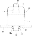
以下、本発明を実施するための最良の形態を、図1〜3を用いて説明する。図1は、クッションクリップの正面図である。図2は、クッションクリップの平面図である。図3は、クッションクリップの縦断面図である。クッションクリップは、係止脚10と、この係止脚10の一部と一体的に接合(例えば、二色成形による接合)されたクッション体20とから構成されている。以下に、係止脚10およびクッション体20の構造を個別に説明する。
Hereinafter, the best mode for carrying out the present invention will be described with reference to FIGS. FIG. 1 is a front view of a cushion clip. FIG. 2 is a plan view of the cushion clip. FIG. 3 is a longitudinal sectional view of the cushion clip. The cushion clip includes a
まず、係止脚10を説明する。係止脚10は、所定の剛性を有するポリプロピレン(PP)などの素材によって成形されている。この係止脚10の構造は、後述するクッション体20の内部に位置する略円柱形状の基部11とクッション体20の外部に位置する係止部12とからなっている(図1、3参照)。この係止部12には、一対の係止爪12aが形成されており、両係止爪12aは係止脚10の軸線(図示しない)側へ撓むことができるように、係止部12に対して弾性をもって一体化されている。
First, the
そして、図1に示すように、車両ボディー30の取付孔32に係止部12が挿入されると、両係止爪12aが撓みながら取付孔32を通過して車両ボディー30の反対側に位置することになる。これにより、係止部12が車両ボディー30に結合され、結果として車両ボディー30にクッションクリップが取り付けられる。なお、車両ボディー30はスライドドア(開閉体)の相手側であるが、このスライドドア側に取付孔を設けて、クッションクリップを取り付ける場合もある。また、図3に示すように、基部11の先端面中央には凹孔11aが形成されている。
As shown in FIG. 1, when the
次に、クッション体20を説明する。クッション体20は、主として開閉体を閉ざすときの衝撃力を緩衝するためのクッション部21から構成されており、その素材は、エラストマやゴムといった比較的軟質の弾性素材である。そして、既に述べたように、このクッション体20は、その内部に基部11を配置させるよう基部11の全てを覆う格好となるように基部11と一体的に接合されている。もちろん、必ずしも基部11の全てを覆う必要はない。クッション部21の先端側中央(図1、3において、上端面中央)には凹部21aが形成されている。この凹部21aの底面には、クッション部21の先端面より突出した第1突出部22がクッション体20と一体に成形されている。
Next, the
また、クッション部21の基端側中央(図3において、基端面中央)には、第1突出部22と反対方向に向けて突出した第2突出部23が基部11の凹孔11aに充填される格好で且つクッション部21と一体に成形されている。
Further, a second projecting
続いて、上述した構成からなるクッションクリップの作用について説明する。このクッションクリップは、既に説明したように、スライドドア(図示省略)の相手側である車両ボディー30に取り付けられており、このスライドドアが閉められたときに衝撃力を受けた場合、この衝撃力によって最初に第1突出部22が縮み方向に変形する。また、この衝撃力によって、第1突出部22と反対方向に位置する第2突出部23までも縮み方向に変形する。その後に、クッション部21が縮み方向に変形する。
Then, the effect | action of the cushion clip which consists of the structure mentioned above is demonstrated. As already described, the cushion clip is attached to the
このように両突出部22、23が変形した後に、クッション部21の変形が始まると、両突出部22、23の両端の距離「A」に対してクッション部21の上下端の距離「B」が短いため(図3参照)、両突出部22、23とクッション部21の弾性素材が同一であるにも関わらず、例えば同じ寸法だけ圧縮しようとした場合、クッション部21より両突出部22、23の方が軟らかくなる。このことは、両突出部22、23の外径に対してクッション部21の外径が大きいことからも生じる要因となる。これらにより、従来技術の説明と同様に、衝撃力を緩衝する際の初期荷重が小さく、その後に急激に荷重を大きくする特性を得ることができる。つまり、両突出部22、23の変形に基づく初期荷重は小さく、その後はクッション部21の変形も加わって荷重が急激に増加する。
When the deformation of the
このように、クッションクリップの初期荷重を小さくすることで、仮にスライドドアが勢いよく閉められた場合であっても、衝撃を柔らかく受け止めてドアの跳ね返り等を防止することができる。また、その後は、クッションクリップの荷重の増加により、スライドドアからの大きな衝撃力を効果的に緩衝することができる。また、スライドドアが閉ざされた位置にあるときは、第1突出部22がスライドドアの周縁部に当接しているため、スライドドアのガタツキを防止することができる。
In this way, by reducing the initial load of the cushion clip, even if the sliding door is momentarily closed, the impact can be softly received to prevent the door from rebounding. Thereafter, a large impact force from the sliding door can be effectively buffered by increasing the load of the cushion clip. In addition, when the slide door is in the closed position, the
また、このクッションクリップによれば、クッション体20の内部に基部11が配置されているため、クッション体20に必要な弾性素材の量を削減することができる。また、弾性素材量の削減により、成形時間を短縮できるため、クッションクリップの製造コストを低減させることができる。また、既に説明したように、基部11の基端側(図3において、下端側)もクッション体20によって覆われているため、クッションクリップを車両ボディーに取り付けた状態でも、基部11と車両ボディー30とが接触することがない。これにより、ドアを閉めたときに打音が生じることがない。
Moreover, according to this cushion clip, since the
上述した内容は、あくまでも本発明の一実施の形態に関するものであって、本発明が上記内容に限定されることを意味するものではない。
実施例では、開閉体がスライドドアである場合を例に説明した。しかし、これに限定されるものでなく、開閉体がグローブボックスであっても構わない。
The contents described above are only related to one embodiment of the present invention, and do not mean that the present invention is limited to the above contents.
In the embodiment, the case where the opening / closing body is a slide door has been described as an example. However, the present invention is not limited to this, and the opening / closing body may be a glove box.
10 係止脚
11 基部
11a 凹孔
12 係止部
12a 係止爪
20 クッション体
21 クッション部
21a 凹部
22 第1突出部
23 第2突出部
30 車両ボディー
32 取付孔
DESCRIPTION OF
Claims (1)
前記クッション部の先端側中央には凹部が形成されており、
前記凹部の底面には前記先端面より突出した第1突出部が該クッション部と一体に成形されており、
前記基部の先端面中央には凹孔が形成されており、
前記クッション部の基端側中央には、前記第1突出部と反対方向に向けて突出した第2突出部が前記基部の凹孔に充填される格好で且つ該クッション部と一体に成形されているクッションクリップであって、
第2突出部の外径は、第1突出部の外径より大きくなるように設定されているクッションクリップ。 A cushion body having a cushion portion for buffering an impact force, and a locking leg including a base portion positioned inside the cushion body and a locking portion positioned outside the cushion body, and opening and closing the locking portion It is possible to buffer the impact force when closing the opening and closing body by inserting it into the mounting hole of the body or its counterpart and coupling it,
A concave portion is formed at the front end side center of the cushion portion,
A first projecting portion projecting from the front end surface is formed integrally with the cushion portion on the bottom surface of the concave portion,
A concave hole is formed in the center of the tip surface of the base,
At the center on the base end side of the cushion portion, a second protrusion that protrudes in the opposite direction to the first protrusion is shaped so as to be filled in the concave hole of the base, and is integrally formed with the cushion portion. A cushion clip ,
A cushion clip , wherein the outer diameter of the second protrusion is set to be larger than the outer diameter of the first protrusion .
Priority Applications (1)
| Application Number | Priority Date | Filing Date | Title |
|---|---|---|---|
| JP2007034593A JP5031394B2 (en) | 2007-02-15 | 2007-02-15 | Cushion clip |
Applications Claiming Priority (1)
| Application Number | Priority Date | Filing Date | Title |
|---|---|---|---|
| JP2007034593A JP5031394B2 (en) | 2007-02-15 | 2007-02-15 | Cushion clip |
Publications (2)
| Publication Number | Publication Date |
|---|---|
| JP2008196651A JP2008196651A (en) | 2008-08-28 |
| JP5031394B2 true JP5031394B2 (en) | 2012-09-19 |
Family
ID=39755781
Family Applications (1)
| Application Number | Title | Priority Date | Filing Date |
|---|---|---|---|
| JP2007034593A Expired - Fee Related JP5031394B2 (en) | 2007-02-15 | 2007-02-15 | Cushion clip |
Country Status (1)
| Country | Link |
|---|---|
| JP (1) | JP5031394B2 (en) |
Families Citing this family (5)
| Publication number | Priority date | Publication date | Assignee | Title |
|---|---|---|---|---|
| JP2011241962A (en) | 2010-05-21 | 2011-12-01 | Daiwa Kasei Kogyo Kk | Cushioning clip |
| KR101386670B1 (en) * | 2012-09-07 | 2014-04-17 | 인지컨트롤스 주식회사 | Headlamp lighting derection controller |
| KR101460629B1 (en) * | 2013-06-28 | 2014-11-13 | 인지컨트롤스 주식회사 | Back Light Direction Shifting Device for a Vehicle Head Lamp and Assembling Method thereof |
| US9181745B1 (en) | 2014-05-21 | 2015-11-10 | Newfrey Llc | Trunk cushion assembly |
| CN115306245A (en) * | 2022-08-26 | 2022-11-08 | 浙江极氪智能科技有限公司 | Buffer structure and vehicle |
Family Cites Families (5)
| Publication number | Priority date | Publication date | Assignee | Title |
|---|---|---|---|---|
| JPS61218844A (en) * | 1985-03-26 | 1986-09-29 | Kinugawa Rubber Ind Co Ltd | Hood bumper rubber |
| JPS62113930A (en) * | 1985-11-13 | 1987-05-25 | Kinugawa Rubber Ind Co Ltd | Bumper rubber of closing unit for vehicle |
| JP2003202043A (en) * | 2002-01-08 | 2003-07-18 | Daiwa Kasei Ind Co Ltd | Cushioning clip |
| JP2006057283A (en) * | 2004-08-18 | 2006-03-02 | Toyota Auto Body Co Ltd | Cushion member |
| JP2006097326A (en) * | 2004-09-29 | 2006-04-13 | Daiwa Kasei Ind Co Ltd | Cushion clip |
-
2007
- 2007-02-15 JP JP2007034593A patent/JP5031394B2/en not_active Expired - Fee Related
Also Published As
| Publication number | Publication date |
|---|---|
| JP2008196651A (en) | 2008-08-28 |
Similar Documents
| Publication | Publication Date | Title |
|---|---|---|
| JP6147508B2 (en) | Cushion clip | |
| US8291547B2 (en) | Cushion clip | |
| JP5360498B2 (en) | Clamp | |
| US20100192335A1 (en) | Cushion clip | |
| KR100563780B1 (en) | Mounting structure of a vehicle interior part | |
| JP2006153083A (en) | Cushioning clip | |
| JP5031394B2 (en) | Cushion clip | |
| JP6328476B2 (en) | clip | |
| CN105339703A (en) | Vibration-damping device | |
| JP2011241962A (en) | Cushioning clip | |
| US9739337B2 (en) | Vibration damping device | |
| JP2007225093A (en) | Cushion clip | |
| JP4522977B2 (en) | Inside door handle device | |
| JP5095450B2 (en) | Cushion clip | |
| JP2003202043A (en) | Cushioning clip | |
| JP2006097326A (en) | Cushion clip | |
| JP2010001967A (en) | Cushion clip | |
| US9505285B2 (en) | Anti-vibration device | |
| JP2002349524A (en) | Cushioning clip and its molding method | |
| JP2006052806A (en) | Cushion clip | |
| JP2006097775A (en) | Vehicular cushion rubber | |
| JP2021196043A (en) | Cushion clip | |
| JP2014190105A (en) | Slide door stopper | |
| JP6405719B2 (en) | Hitting pad | |
| JP2001151160A (en) | Bumper rubber |
Legal Events
| Date | Code | Title | Description |
|---|---|---|---|
| A621 | Written request for application examination |
Free format text: JAPANESE INTERMEDIATE CODE: A621 Effective date: 20100122 |
|
| A977 | Report on retrieval |
Free format text: JAPANESE INTERMEDIATE CODE: A971007 Effective date: 20110331 |
|
| A131 | Notification of reasons for refusal |
Free format text: JAPANESE INTERMEDIATE CODE: A131 Effective date: 20110920 |
|
| A521 | Written amendment |
Free format text: JAPANESE INTERMEDIATE CODE: A523 Effective date: 20111104 |
|
| TRDD | Decision of grant or rejection written | ||
| A01 | Written decision to grant a patent or to grant a registration (utility model) |
Free format text: JAPANESE INTERMEDIATE CODE: A01 Effective date: 20120605 |
|
| A01 | Written decision to grant a patent or to grant a registration (utility model) |
Free format text: JAPANESE INTERMEDIATE CODE: A01 |
|
| A61 | First payment of annual fees (during grant procedure) |
Free format text: JAPANESE INTERMEDIATE CODE: A61 Effective date: 20120627 |
|
| R150 | Certificate of patent or registration of utility model |
Free format text: JAPANESE INTERMEDIATE CODE: R150 |
|
| FPAY | Renewal fee payment (event date is renewal date of database) |
Free format text: PAYMENT UNTIL: 20150706 Year of fee payment: 3 |
|
| R250 | Receipt of annual fees |
Free format text: JAPANESE INTERMEDIATE CODE: R250 |
|
| LAPS | Cancellation because of no payment of annual fees |