JP6399524B2 - Footwear products incorporating knit components with integrated knit contours - Google Patents
Footwear products incorporating knit components with integrated knit contours Download PDFInfo
- Publication number
- JP6399524B2 JP6399524B2 JP2015561475A JP2015561475A JP6399524B2 JP 6399524 B2 JP6399524 B2 JP 6399524B2 JP 2015561475 A JP2015561475 A JP 2015561475A JP 2015561475 A JP2015561475 A JP 2015561475A JP 6399524 B2 JP6399524 B2 JP 6399524B2
- Authority
- JP
- Japan
- Prior art keywords
- base
- path
- base portion
- strand
- knit
- Prior art date
- Legal status (The legal status is an assumption and is not a legal conclusion. Google has not performed a legal analysis and makes no representation as to the accuracy of the status listed.)
- Active
Links
Images


Classifications
-
- A—HUMAN NECESSITIES
- A43—FOOTWEAR
- A43B—CHARACTERISTIC FEATURES OF FOOTWEAR; PARTS OF FOOTWEAR
- A43B1/00—Footwear characterised by the material
- A43B1/02—Footwear characterised by the material made of fibres or fabrics made therefrom
- A43B1/04—Footwear characterised by the material made of fibres or fabrics made therefrom braided, knotted, knitted or crocheted
-
- A—HUMAN NECESSITIES
- A43—FOOTWEAR
- A43B—CHARACTERISTIC FEATURES OF FOOTWEAR; PARTS OF FOOTWEAR
- A43B23/00—Uppers; Boot legs; Stiffeners; Other single parts of footwear
- A43B23/02—Uppers; Boot legs
- A43B23/0245—Uppers; Boot legs characterised by the constructive form
-
- A—HUMAN NECESSITIES
- A43—FOOTWEAR
- A43B—CHARACTERISTIC FEATURES OF FOOTWEAR; PARTS OF FOOTWEAR
- A43B23/00—Uppers; Boot legs; Stiffeners; Other single parts of footwear
- A43B23/02—Uppers; Boot legs
- A43B23/0245—Uppers; Boot legs characterised by the constructive form
- A43B23/0265—Uppers; Boot legs characterised by the constructive form having different properties in different directions
-
- A—HUMAN NECESSITIES
- A43—FOOTWEAR
- A43B—CHARACTERISTIC FEATURES OF FOOTWEAR; PARTS OF FOOTWEAR
- A43B23/00—Uppers; Boot legs; Stiffeners; Other single parts of footwear
- A43B23/02—Uppers; Boot legs
- A43B23/0205—Uppers; Boot legs characterised by the material
- A43B23/0235—Different layers of different material
-
- A—HUMAN NECESSITIES
- A43—FOOTWEAR
- A43B—CHARACTERISTIC FEATURES OF FOOTWEAR; PARTS OF FOOTWEAR
- A43B23/00—Uppers; Boot legs; Stiffeners; Other single parts of footwear
- A43B23/02—Uppers; Boot legs
- A43B23/0245—Uppers; Boot legs characterised by the constructive form
- A43B23/025—Uppers; Boot legs characterised by the constructive form assembled by stitching
-
- A—HUMAN NECESSITIES
- A43—FOOTWEAR
- A43B—CHARACTERISTIC FEATURES OF FOOTWEAR; PARTS OF FOOTWEAR
- A43B23/00—Uppers; Boot legs; Stiffeners; Other single parts of footwear
- A43B23/02—Uppers; Boot legs
- A43B23/0245—Uppers; Boot legs characterised by the constructive form
- A43B23/0265—Uppers; Boot legs characterised by the constructive form having different properties in different directions
- A43B23/0275—Uppers; Boot legs characterised by the constructive form having different properties in different directions with a part of the upper particularly rigid, e.g. resisting articulation or torsion
-
- A—HUMAN NECESSITIES
- A43—FOOTWEAR
- A43B—CHARACTERISTIC FEATURES OF FOOTWEAR; PARTS OF FOOTWEAR
- A43B23/00—Uppers; Boot legs; Stiffeners; Other single parts of footwear
- A43B23/02—Uppers; Boot legs
- A43B23/04—Uppers made of one piece; Uppers with inserted gussets
- A43B23/042—Uppers made of one piece
-
- A—HUMAN NECESSITIES
- A43—FOOTWEAR
- A43B—CHARACTERISTIC FEATURES OF FOOTWEAR; PARTS OF FOOTWEAR
- A43B23/00—Uppers; Boot legs; Stiffeners; Other single parts of footwear
- A43B23/26—Tongues for shoes
-
- D—TEXTILES; PAPER
- D04—BRAIDING; LACE-MAKING; KNITTING; TRIMMINGS; NON-WOVEN FABRICS
- D04B—KNITTING
- D04B1/00—Weft knitting processes for the production of fabrics or articles not dependent on the use of particular machines; Fabrics or articles defined by such processes
- D04B1/10—Patterned fabrics or articles
- D04B1/102—Patterned fabrics or articles with stitch pattern
- D04B1/108—Gussets, e.g. pouches or heel or toe portions
-
- D—TEXTILES; PAPER
- D04—BRAIDING; LACE-MAKING; KNITTING; TRIMMINGS; NON-WOVEN FABRICS
- D04B—KNITTING
- D04B1/00—Weft knitting processes for the production of fabrics or articles not dependent on the use of particular machines; Fabrics or articles defined by such processes
- D04B1/10—Patterned fabrics or articles
- D04B1/12—Patterned fabrics or articles characterised by thread material
- D04B1/123—Patterned fabrics or articles characterised by thread material with laid-in unlooped yarn, e.g. fleece fabrics
-
- D—TEXTILES; PAPER
- D04—BRAIDING; LACE-MAKING; KNITTING; TRIMMINGS; NON-WOVEN FABRICS
- D04B—KNITTING
- D04B1/00—Weft knitting processes for the production of fabrics or articles not dependent on the use of particular machines; Fabrics or articles defined by such processes
- D04B1/22—Weft knitting processes for the production of fabrics or articles not dependent on the use of particular machines; Fabrics or articles defined by such processes specially adapted for knitting goods of particular configuration
-
- D—TEXTILES; PAPER
- D10—INDEXING SCHEME ASSOCIATED WITH SUBLASSES OF SECTION D, RELATING TO TEXTILES
- D10B—INDEXING SCHEME ASSOCIATED WITH SUBLASSES OF SECTION D, RELATING TO TEXTILES
- D10B2403/00—Details of fabric structure established in the fabric forming process
- D10B2403/03—Shape features
- D10B2403/032—Flat fabric of variable width, e.g. including one or more fashioned panels
-
- D—TEXTILES; PAPER
- D10—INDEXING SCHEME ASSOCIATED WITH SUBLASSES OF SECTION D, RELATING TO TEXTILES
- D10B—INDEXING SCHEME ASSOCIATED WITH SUBLASSES OF SECTION D, RELATING TO TEXTILES
- D10B2501/00—Wearing apparel
- D10B2501/04—Outerwear; Protective garments
- D10B2501/043—Footwear
Description
本開示は、履物製品に関し、より具体的には、一体化ニット輪郭部分を備えたニット構成要素を組み込んだ履物製品に関する。 The present disclosure relates to footwear products, and more particularly to footwear products incorporating a knitted component with an integral knit contour.
このセクションは、必ずしも従来技術ではない、本開示に関連する背景情報を記載している。 This section provides background information related to the present disclosure that is not necessarily prior art.
従来の履物製品は、一般的に、アッパーおよびソール構造という2つの主要な要素を含んでいる。アッパーは、ソール構造に固定されて、足を快適にかつ安定して受け入れるために、履物の内部に空洞を形成している。ソール構造は、それによってアッパーと地面との間に位置するように、アッパーの下側区域に固定されている。たとえば、運動用の履物では、ソール構造は、ミッドソールとアウトソールとを含んでいてもよい。ミッドソールは、多くの場合、地面の反力を弱めて、歩くとき、走るとき、および他の歩行活動中に足および脚にかかる応力を低減するポリマー発泡材料を含んでいる。くわえて、ミッドソールは、力をさらに弱め、安定性を高め、または足の動きに影響を与える液体充填チャンバ、プレート、モデレータ、または他の要素を含んでいてもよい。アウトソールは、ミッドソールの下面に固定されて、ゴム等の耐久性のある耐摩耗性材料から形成されたソール構造の地面係止部を形成している。また、ソール構造は、履物の快適性を高めるために、空洞内に配置され、足の下面に近接する中敷きも含んでいてもよい。 Conventional footwear products generally include two main elements: an upper and a sole structure. The upper is fixed to the sole structure and forms a cavity inside the footwear to receive the foot comfortably and stably. The sole structure is secured to the lower area of the upper so that it lies between the upper and the ground. For example, in athletic footwear, the sole structure may include a midsole and an outsole. The midsole often includes a polymeric foam material that reduces ground reaction forces and reduces stress on the feet and legs when walking, running, and during other walking activities. In addition, the midsole may include liquid-filled chambers, plates, moderators, or other elements that further reduce forces, increase stability, or affect foot movement. The outsole is fixed to the lower surface of the midsole and forms a ground engaging portion of a sole structure formed of a durable wear-resistant material such as rubber. The sole structure may also include an insole disposed within the cavity and proximate to the lower surface of the foot to enhance the comfort of the footwear.
アッパーは、大略的に、足の甲およびつま先区域にわたり、足の内側側部および外側側部に沿って、足のかかと区域の周りに延びている。バスケットボール用履物およびブーツなどいくつかの履物製品では、アッパーは、足首の上方および足首の周りに延びて、足首に支持または保護を与えてもよい。アッパーの内部の空洞へのアクセスは、一般的に、履物のかかと領域にある足首開口部によってもたらされる。アッパーの履き心地を調整するために、しばしば締めひもシステムがアッパーに組み込まれ、それによりアッパー内の空洞に足を入れ、および空洞から足を抜くことが可能になる。また、締めひもシステムにより、着用者が、アッパーの特定の寸法、特に周長を調節して、さまざまな寸法の足を収容することもできる。くわえて、アッパーは、締めひもシステムの下に延びて、履物の調節可能性を高める舌革を含んでいてもよく、アッパーは、かかとの動きを制限するために、ヒールカウンタを組み込んでいてもよい。 The upper extends generally around the heel area of the foot, along the medial and lateral sides of the foot, over the instep and toe areas. In some footwear products, such as basketball footwear and boots, the upper may extend above and around the ankle to provide support or protection to the ankle. Access to the cavity inside the upper is generally provided by an ankle opening in the heel area of the footwear. To adjust the comfort of the upper, a lace system is often incorporated into the upper, which allows the foot to enter and withdraw from the cavity in the upper. The lacing system also allows the wearer to accommodate specific dimensions of the upper, particularly the circumference, to accommodate feet of various dimensions. In addition, the upper may include a tongue that extends below the lace system to increase the adjustability of the footwear, and the upper may incorporate a heel counter to limit heel movement. Good.
さまざまな材料要素(たとえば、織物、ポリマー発泡体、ポリマーシート、革、合成皮革)が、従来、アッパーを製造する際に利用されている。たとえば、運動用の履物では、アッパーは、それぞれが様々な接合材料要素を含む複数の層を有していてもよい。例として、それらの材料要素は、耐伸縮性、耐摩耗性、柔軟性、通気性、圧縮性、快適性および速乾性を、アッパーの異なる区域に付与するように選択してもよい。アッパーの異なる区域に異なる特性を付与するために、材料要素は、所望の形状に切断してから、通常は、縫製または接着剤で互いに接合することが多い。また、材料要素は、同じ区域に複数の特性を付与するために、層状構成で接合されることが多い。アッパーに組み込まれる材料要素の数および種類が増えるにつれ、材料要素の輸送、保管、切断および接合に関連する時間および費用も増加する可能性がある。切断および縫製プロセスから出る廃材も、アッパーに組み込まれる材料要素の数および種類が増えるにつれて、さらに多く蓄積する。さらに、アッパーの材料要素の数が多くなるほど、種類および数が少ない材料要素から形成されたアッパーよりもリサイクルが難しくなることがある。そのため、アッパーに利用する材料要素の数を減らすことにより、アッパーの製造効率およびリサイクル性を高めながら、廃棄物を少なくすることができる。 Various material elements (eg, woven fabrics, polymer foams, polymer sheets, leather, synthetic leather) are conventionally used in manufacturing uppers. For example, in athletic footwear, the upper may have multiple layers, each containing various joining material elements. By way of example, these material elements may be selected to impart stretch resistance, abrasion resistance, flexibility, breathability, compressibility, comfort and quick drying to different areas of the upper. In order to impart different properties to different areas of the upper, the material elements are often cut into the desired shape and then joined together, usually with sewing or adhesive. Also, the material elements are often joined in a layered configuration to impart multiple properties to the same area. As the number and type of material elements incorporated into the upper increases, the time and costs associated with transporting, storing, cutting and joining the material elements can also increase. More waste material from the cutting and sewing process accumulates as the number and type of material elements incorporated into the upper increases. In addition, the greater the number of material elements in the upper, the more difficult it may be to recycle than an upper formed from fewer and fewer material elements. Therefore, by reducing the number of material elements used for the upper, waste can be reduced while improving the manufacturing efficiency and recyclability of the upper.
このセクションは、本開示の概要を記載しているが、その全範囲またはその特徴のすべてに関する包括的な開示ではない。 This section provides an overview of the disclosure, but is not a comprehensive disclosure of its full scope or all of its features.
ソール構造に接続されるように構成され、および足を受け入れるように構成されている履物製品用アッパーが開示されている。そのアッパーは、一体ニット構造を有するニット構成要素を含んでいる。そのニット構成要素は、ソール構造に隣接して配置されるように構成されたベース部を有している。また、ニット構成要素は、ベース部の両端部から延びているかかと部および足先部も含んでいる。さらに、ニット構成要素は、ベース部の両側部から延びている内側部および外側部を含んでいる。内側部および外側部は、内側部と外側部との間にスロート区域を画成するように協働する。さらに、ニット構成要素は、そのスロート区域内に配置されるように構成されている舌革部を含んでいる。舌革部は、内側部および外側部の少なくとも一方からは分離されている。また、アッパーは、ニット構成要素の第1の縁部と、ニット構成要素の第2の縁部とを含んでいる。第2の縁部は、縫い目で第1の縁部に結合されて、ベース部、かかと部、足先部、内側部および外側部に、足を受け入れるように構成される空洞を協働して画成させるように構成されている。 An upper for a footwear product configured to be connected to a sole structure and configured to receive a foot is disclosed. The upper includes a knit component having a unitary knit structure. The knit component has a base portion configured to be disposed adjacent to the sole structure. The knit component also includes a heel portion and a foot portion extending from both ends of the base portion. Further, the knit component includes an inner portion and an outer portion that extend from both sides of the base portion. The inner and outer portions cooperate to define a throat area between the inner and outer portions. In addition, the knit component includes a tongue that is configured to be disposed within the throat area. The tongue part is separated from at least one of the inner part and the outer part. The upper also includes a first edge of the knitted component and a second edge of the knitted component. The second edge is coupled to the first edge with a seam and cooperates with a cavity configured to receive the foot in the base, heel, toe, medial and lateral parts. It is configured to define.
くわえて、ソール構造に接続されるように構成されている履物製品用ニット構成要素を製造する方法が開示されている。その方法は、ソールに隣接して配置されるように構成されたベース部と、ベース部の両端部から延びるかかと部および足先部と、ベース部の両側部から延びる内側部および外側部とを有するようにニット構成要素を編むことを含んでいる。内側部および外側部は、内側部と外側部との間にスロート区域を画成するように協働する。さらに、ニット構成要素を編むことは、スロート区域内に配置されるように構成されている舌革部を編むことを含んでいる。舌革部は、内側部および外側部の少なくとも一方からは分離されている。さらに、この方法は、ニット構成要素の第1の縁部と、ニット構成要素の第2の縁部とを縫い目で結合して、ベース部、かかと部、足先部、内側部および外側部に、足を受け入れるように構成される空洞を協働して画成させることを含んでいる。 In addition, a method of manufacturing a knitted component for footwear configured to be connected to a sole structure is disclosed. The method includes a base portion configured to be disposed adjacent to the sole, a heel portion and a foot portion extending from both ends of the base portion, and an inner portion and an outer portion extending from both sides of the base portion. Including knitting the knit component to have. The inner and outer portions cooperate to define a throat area between the inner and outer portions. Further, knitting the knitted component includes knitting a tongue that is configured to be disposed within the throat area. The tongue part is separated from at least one of the inner part and the outer part. Further, the method includes joining the first edge of the knitted component and the second edge of the knitted component with a seam to the base portion, the heel portion, the toe portion, the inner portion, and the outer portion. Including cooperatively defining a cavity configured to receive a foot.
さらに、ソール構造に接続されるように構成されており、および足を受け入れるように構成されている履物製品用アッパーが開示されている。そのアッパーは、ソール構造に隣接して配置されるように構成されているベース部を有するニット構成要素を含んでいる。そのベース部は、ニット構成要素の内側面および外側面を画成している。ベース部は、その内側面と外側面との間にベース部経路を画成している。また、アッパーは、ベース部経路を通って延びている伸張性ストランドを含んでいる。 Further disclosed is an upper for a footwear product configured to be connected to a sole structure and configured to receive a foot. The upper includes a knit component having a base portion configured to be disposed adjacent to the sole structure. The base portion defines an inner surface and an outer surface of the knit component. The base portion defines a base portion path between the inner surface and the outer surface. The upper also includes extensible strands that extend through the base channel.
さらに、ソール構造に接続されるように構成されており、および足の上に装着されるように構成されているアッパーを製造する方法が開示されている。その方法は、ソール構造に隣接して配置されるように構成されているベース部を有するニット構成要素を編むことを含んでいる。そのベース部は、ニット構成要素の内側面および外側面を画成している。ベース部は、その内側面と外側面との間にベース部経路を画成している。その方法は、ベース部経路を通して伸張性ストランドを延ばすことを追加的に含む。 Further disclosed is a method for manufacturing an upper configured to be connected to a sole structure and configured to be worn on a foot. The method includes knitting a knit component having a base portion configured to be disposed adjacent to a sole structure. The base portion defines an inner surface and an outer surface of the knit component. The base portion defines a base portion path between the inner surface and the outer surface. The method additionally includes extending the extensible strand through the base path.
くわえて、ソール構造およびアッパーを含む履物製品が開示されている。そのアッパーは、一体ニット構造を有するニット構成要素を含んでいる。また、そのニット構成要素は、ソール構造に隣接して配置されるように構成されているベース部も含んでいる。そのベース部は、ニット構成要素の内側面および外側面を画成している。また、ベース部は、その内側面と外側面との間にベース部経路も画成している。さらに、履物製品は、ベース部経路を通って延びている伸張性ストランドを含んでいる。 In addition, an article of footwear including a sole structure and an upper is disclosed. The upper includes a knit component having a unitary knit structure. The knit component also includes a base portion configured to be disposed adjacent to the sole structure. The base portion defines an inner surface and an outer surface of the knit component. The base portion also defines a base portion path between the inner side surface and the outer side surface. In addition, the footwear product includes extensible strands that extend through the base channel.
適用性のさらなる範囲は、本願明細書に記載されている説明から明らかになるであろう。この概要における説明および具体的な実施例は、例示目的だけが意図されており、本開示の範囲を限定するように意図されていない。 Further scope of applicability will become apparent from the description provided herein. The description and specific examples in this summary are intended for purposes of illustration only and are not intended to limit the scope of the present disclosure.
本願明細書に記載されている図面は、選択された実施形態およびすべてではない可能性のある実施態様の例示のためのものにすぎず、本開示の範囲を限定するように意図されていない。 The drawings described herein are merely illustrative of selected embodiments and embodiments that may not be all, and are not intended to limit the scope of the disclosure.
対応する参照数字は、図面の各図を通して対応する部材を示している。 Corresponding reference numerals indicate corresponding parts throughout the drawings.
次に、添付図面を参照して、実施態様例についてより完全に説明する。 Embodiments will now be described more fully with reference to the accompanying drawings.
履物製品に関する一般的考察
最初に、図1〜図3を参照すると、例示的な実施形態による履物製品100が図示されている。履物100は、大略的に、ソール構造110と、アッパー120とを含むことができる。
General Considerations for Footwear Products Referring initially to FIGS. 1-3, an
ソール構造110は、アッパー120に固定されており、履物100が着用された場合に、足と地面との間に延びている。ソール構造110は、互いに重なり合っているミッドソール112およびアウトソール114を含むことができる。ミッドソール112は、弾性的に圧縮可能な材料、液体充填ブラダー等を含むことができる。したがって、ミッドソール112は、着用者の足に対してクッションの働きをし、走っているとき、ジャンプしたとき等の場合の衝撃およびその他の力を弱めることができる。アウトソール114は、ミッドソール112に固定することができ、ゴム等の耐摩耗材料を含むことができる。また、アウトソール114は、トレッドおよび他の静止摩擦強化形状構成も含むことができる。
The
さらに、アッパー120は、着用者の足を受け入れる空洞122を画成することができる。換言すれば、アッパー120は、空洞122を画成している内側面121を画成することができ、およびアッパー120は、内側面121の反対側の方向に対向している外側面123を画成することができる。着用者の足が空洞122内に受け入れられると、アッパー120は、着用者の足を少なくとも部分的に包囲して包み込むことができる。
Further, the upper 120 can define a
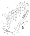
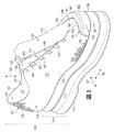
多くの従来の履物のアッパーは、たとえば、縫製または接着により接合されている複数の材料要素(たとえば、織物、ポリマー発泡体、ポリマーシート、革、合成皮革)から形成されている。対して、アッパー120の少なくとも一部は、一体ニット構造を有するニット構成要素116から形成されている。ニット構成要素116の外側境界は、図5および図6に図示されている周辺縁部199によって画成することができる。説明されるように、ニット構成要素116は、アッパー120内の空洞の少なくとも一部を画成することができる。また、ニット構成要素116は、アッパー120の外側面123および/または内側面121の少なくとも一部を画成することができる。
Many conventional footwear uppers are formed from a plurality of material elements (eg, fabric, polymer foam, polymer sheet, leather, synthetic leather) that are joined together, for example, by sewing or gluing. In contrast, at least a portion of the upper 120 is formed from a
いくつかの実施形態において、ニット構成要素116は、アッパー120の大部分を画成することができる。アッパー120を形成する際に使用される材料要素の数を減らせば、廃棄物を減らせる可能性があり、また同時に、アッパー120の製造効率およびリサイクル性を向上させることができる。以下でより詳細に説明するように、本開示のアッパー120のニット構成要素116は、廃棄物を減らすことができ、および製造効率およびリサイクル性を向上させることができる。くわえて、アッパー120のニット構成要素116は、より少数の縫い目または他の不連続部を組み込むことができ、それによって、履物100全体の快適性を高めることができる。
In some embodiments, the
ニット構成要素116は、同じストランド、ヤーン(または、ヤーンの種類)から、または同様のニット構造で形成する場合、共通の特性を有してもよい。たとえば、ニット構成要素116のさまざまな部分に同じストランドを使用することにより、同様の耐久性、強度、伸縮性、耐摩耗性、生物分解性、熱特性および疎水性を与えることができる。ニット構成要素116の複数の部分に同じストランドを使用することにより、物理的特性に加えて、色、光沢および質感等の共通の美的特性または触覚特性を与えることができる。また、ニット構成要素116の異なる部分全域に同じニット構造を用いることにより、共通の物理的特性および美的特性を与えることもできる。
The knitted
ニット構成要素の構成
図4〜図6は、図1〜図3の例示的な実施形態と同じ方法で履物製品に組み込んでもよいニット構成要素116のさまざまな実施形態を示す。図4〜図6に図示されているニット構成要素116は、履物100の残りの部分から分離されて描かれている。しかし、本願明細書に記載されているニット構成要素116の実施形態の各々は、ニット構成要素116を組み込んだ履物製品100を形成するために、上述した履物100の要素と組み合わせてもよいことを理解すべきである。
Knit Component Configuration FIGS. 4-6 illustrate various embodiments of a
ニット構成要素116は、「一体ニット構造」にすることができる。本願明細書において定義する場合、およびクレームにおいて用いる場合、「一体ニット構造」という用語は、ニット構成要素116が、編みプロセスによってワンピース要素として形成されることを意味する。すなわち、編みプロセスは、大幅な追加的製造工程またはプロセスを要することなく、ニット構成要素116のさまざまな形状構成および構造を実質的に形成する。一体ニット構造は、その構造または要素が、少なくとも1つのコースを共通して含み(すなわち、共通ストランドまたは共通ヤーンを共有している)、および/またはニット構成要素116の各部分の間で実質的に連続しているコースを含むように接合されているヤーンまたは他のニット材料の1つ以上のコースを含む該構造または要素を有するニット構成要素を形成するのに用いてもよい。この構成によって、一体ニット構造から成るワンピース要素が形成される。
The
ニット構成要素116の部分は、編みプロセスの後に互いに接合してもよいが、ニット構成要素116は、ワンピースニット要素として形成されているため、依然として一体ニット構造で形成されたままである。また、ニット構成要素116は、編みプロセスの後に、他の要素(たとえば、インレイストランド、クロージャー要素、ロゴ、商標、注意書きおよび材料情報を記載した札、およびその他の構造的要素)が付加された場合でも、依然として一体ニット構造で形成されたままである。
The portions of the knitted
図4〜図6は、履物製品100のアッパー120の大部分を画成する場合のニット構成要素116の例示的な実施形態を示す。図示されているように、アッパー120のニット構成要素116は、ベース部124またはストローベル部または足元部を含むことができる。また、ニット構成要素116は、1つ以上の側部126を含むことができる。ベース部124は、ソール構造110に隣接して配置されるように構成することができる。たとえば、ベース部124は、ソール構造110を覆って位置するように、ソール構造110に直接的または間接的に付着させることができる。追加的な実施形態においては、他のパーツが取り外されているか、または分離されているままで、ベース部124の1つ以上のパーツ(たとえば、ベース部124の周辺部)をソール構造110に付着させることができる。また、ベース部124は、着用者の足の下に延びるように構成することができる。側部126は、ベース部124から延びることができ、および着用者の足を少なくとも部分的に覆うように構成することができる。また、ベース部124および側部126は、着用者の足を受け入れる空洞122を画成するように協働することができる。ここでもまた、ベース部124および側部126は、上述したような一体ニット構造で形成することができる。
4-6 illustrate an exemplary embodiment of the knitted
図示されている実施形態に示すように、ニット構成要素116の側部126は、かかと部128と、外側部130と、内側部132と、足先部134と、舌革部136とを含むことができ、これらの各々は、ベース部124と同じ一体ニット構造で形成されている。したがって、ニット構成要素116は、着用者の足にしっかりフィットして適合させることができる。また、この構造のため、ニット構成要素116は、比較的迅速に形成して、製造効率を高めることができる。
As shown in the illustrated embodiment, the
また、図6に図示されているように、および詳細に説明するように、ニット構成要素116は、ニット構成要素116の一体ニット構造と組み合わされた1つ以上の伸張性ストランド158を含むことができる。たとえば、ストランド158は、説明されるように、ニット構成要素116のコースおよび/またはウェール内に挿入することができる。また、ストランド158は、ニット構成要素116の内側面および/または外側面に付着させることができる。
Also, as illustrated in FIG. 6 and described in detail, the
ストランド158は、着用者の足の側部および/または下を横切って延びるようにアッパーに配置することができる。また、ストランド158は、靴ひも155等のクロージャー部材154に操作可能に結合することができる。したがって、靴ひも155に張力を加えることにより、同様にストランド158に張力を加えることができる。その結果、ストランド158は、快適性の向上およびより良好なフィット性のための着用者の足に対する支持を与えることができる。
The
アッパー120および履物100の図示されている実施形態は、着用者の左足に着用されるように構成されている。しかし、履物100は、右足に着用されるように構成することができ、および図示されている実施形態と同様の形状構成を含むことができることは正しく認識されるであろう。
The illustrated embodiment of the upper 120 and
履物100は、ランニングシューズとして構成することもできる。しかし、履物100は、たとえば、野球靴、バスケットボールシューズ、サイクリングシューズ、フットボールシューズ、テニスシューズ、サッカーシューズ、トレーニングシューズ、ウォーキングシューズおよびハイキングブーツを含むさまざまな他の運動用の履物の種類にも適用してもよい。また、この概念は、ドレスシューズ、ローファー、サンダルおよび作業靴を含む、一般に非運動用と考えられる履物の種類にも適用してもよい。したがって、履物100に関して開示されている概念は、多様な履物の種類に当てはまる。
The
ニット構成要素の例示的な形状構成
図13に模式的に図示されている例示的な実施形態において、ニット構成要素116の主要な要素は、さまざまなコースおよびウェールを画成する複数の互いにかみ合うループを形成するように(たとえば、編み機を用いて)操作される少なくとも1つのヤーン1138または他のストランドから形成してもよい。ヤーン1138は、この構成において、コースおよびウェールの各々を形成しているが、追加的なヤーンが、1つ以上のコースおよび/またはウェールを形成してもよい。
Exemplary Shape Configuration of Knit Component In the exemplary embodiment schematically illustrated in FIG. 13, the primary element of the
特定の種類のヤーンが、ニット構成要素の区域に付与することになる特性は、ヤーン内のさまざまなフィラメントおよび繊維を形成している材料に部分的に依存する。たとえば、綿は、柔らかな手触り、自然な美観、および生物分解性をもたらす。エラステインおよび伸縮性ポリエステルは、それぞれ、かなりの伸縮性および復元力をもたらし、伸縮性ポリエステルはリサイクル性ももたらす。レーヨンは、光沢に優れ、吸湿性をもたらす。ウールも断熱性および生物分解性に加えて、高い吸湿性をもたらす。ナイロンは、比較的強度が高い、耐久性がある耐擦過性材料である。ポリエステルは、比較的高い耐久性をもたらす疎水性材料である。 The properties that a particular type of yarn will impart to the area of the knitted component will depend in part on the material forming the various filaments and fibers within the yarn. For example, cotton provides a soft hand, natural aesthetics, and biodegradability. Elastane and stretchable polyester provide considerable stretch and resilience, respectively, and stretchable polyester also provides recyclability. Rayon is excellent in gloss and provides moisture absorption. Wool also provides high hygroscopicity in addition to thermal insulation and biodegradability. Nylon is a durable, scratch-resistant material with relatively high strength. Polyester is a hydrophobic material that provides relatively high durability.
ニット構成要素116の部分のための適切な構成の追加的な実施例が図14に描かれている。この構成では、ニット構成要素116は、ヤーン1138と、別のヤーン1139と(すなわち、複数のストランド)を含んでいる。ヤーン1138および1139は、添え糸編みされて、複数の水平コースおよび垂直方向のウェールを画成する複数の互いにかみ合うループを協働して形成している。すなわち、ヤーン1138および1139は、互いに平行に伸びている。この構成の利点は、ヤーン1138および1139のそれぞれの特性が、ニット構成要素1130のこの区域に存在してもよいということである。たとえば、ヤーン1138の色が主にニット要素1131のさまざまなステッチの表面に現れ、ヤーン1139の色が主にニット要素1131のさまざまなステッチの裏面に現れるとすれば、ヤーン1138および1139は、異なる色を有していてもよい。別の実施例として、ヤーン1138が主に第1の面1136に現れ、ヤーン1139が主に第2の面1137に現れるとすれば、ヤーン1139は、ヤーン1138よりも柔らかく、足に対してより快適なヤーンから形成してもよい。
Additional examples of suitable configurations for portions of the knitted
さらに、図13および図14に図示されているように、ストランド1132は、ニット構成要素116の一体ニット構造に組み込むことができる。ストランド1132は、ニット構成要素116に対する支持をもたらす伸張性ストランド要素とすることができる。換言すれば、ストランド1132内の張力は、ニット構成要素116が、ランニング、ジャンプ、または、着用者の足のその他の動きの最中の変形、伸張に耐えること、または、着用者の足のための支持を他の形で与えることを可能にする。また、(上述し、および以下に詳細に記載されている)図6のストランド158を、図13および図14のストランド1132と同様に、ニット構成要素116に組み込むことができることは正しく認識されるであろう。
Further, as illustrated in FIGS. 13 and 14, the
説明されるように、ストランド1132は、編み機上での編みプロセス中に組み込むことができるように、ニット構成要素116の一体ニット構造に組み込むか、または挿入することができる。たとえば、ストランド1132は、図13および図14に図示されているようなニット構成要素116のコースおよび/またはウェールの一方に沿って延びるように、一体ニット構造に挿入することができる。図13および図14に図示されているように、ストランド1132は、(a)ヤーン1138から形成されたループの背後と、(b)ヤーン1138から形成されたループの前とに交互に配置することができる。実際には、インレイストランド1132は、ニット要素1131の一体ニット構造を縫うように通っている。
As described, the
ニット構成要素は、熱硬化性ポリマーおよび天然繊維(たとえば、綿、ウール、絹)のうちの少なくとも一方から形成されている1つ以上のストランドまたはヤーンを含んでいてもよい。他のヤーンまたはストランドは、熱可塑性ポリマー材料から形成してもよい。一般に、熱可塑性ポリマー材料は、加熱されると溶け、冷却されると固体状態に戻る。より具体的には、熱可塑性ポリマー材料は、十分な熱にさらされると、固体状態から軟化した状態または液体状態に遷移し、その後、熱可塑性ポリマー材料は、十分に冷却されると、軟化した状態または液体状態から固体状態に遷移する。したがって、熱可塑性ポリマー材料は、多くの場合、2つの物体または要素を一緒に接合するために使用される。この場合、ヤーンは、たとえば、(a)ヤーンのある部分をヤーンの別の部分に、(b)ヤーンとインレイストランドとを互いに、または(c)別の要素(たとえば、ロゴ、商標、および注意書きおよび材料情報を記載した札)をニット構成要素に接合するために利用してもよい。したがって、ヤーンは、ニット構成要素の部分を互いに融着または他の形で接合するために使用してもよいのであれば、融着性ヤーンと見なしてもよい。また、ヤーンは、一般に、ニット構成要素の部分を互いに融着または他の形で接合できる材料から形成されていないのであれば、非融着性ヤーンと見なしてもよい。すなわち、ヤーンは、非融着性ヤーンであってもよく、一方、他のヤーンは、融着性ヤーンであってもよい。ニット構成要素のいくつかの構成では、ヤーン(すなわち、非融着性ヤーン)は、実質的に、熱硬化性ポリエステル材料から形成してもよく、また、ヤーン(すなわち、融着性ヤーン)は、少なくとも部分的に熱可塑性ポリエステル材料から形成してもよい。 The knitted component may include one or more strands or yarns formed from at least one of thermosetting polymers and natural fibers (eg, cotton, wool, silk). Other yarns or strands may be formed from a thermoplastic polymer material. In general, thermoplastic polymer materials melt when heated and return to a solid state when cooled. More specifically, a thermoplastic polymer material transitions from a solid state to a softened or liquid state when exposed to sufficient heat, after which the thermoplastic polymer material softens when sufficiently cooled. Transition from a state or liquid state to a solid state. Thus, thermoplastic polymer materials are often used to join two objects or elements together. In this case, the yarn is, for example, (a) one part of the yarn to another part of the yarn, (b) the yarn and the inlay strand to each other, or (c) another element (eg, logo, trademark, and attention) A tag with writing and material information) may be used to join the knit component. Thus, a yarn may be considered a fusible yarn if it may be used to fuse or otherwise join portions of a knitted component together. Also, a yarn may generally be considered a non-fusible yarn if it is not formed from a material that allows parts of the knitted component to be fused or otherwise joined together. That is, the yarns may be non-fusible yarns, while the other yarns may be fusible yarns. In some configurations of the knitted component, the yarn (ie, non-fusible yarn) may be substantially formed from a thermoset polyester material, and the yarn (ie, fusible yarn) is , May be at least partially formed from a thermoplastic polyester material.
添え糸編みしたヤーンの使用は、ニット構成要素に利点を付与することができる。ヤーンが加熱されて、ヤーンおよびインレイストランドに融着する場合、このプロセスには、ニット構成要素の構造を剛くまたは堅くするという効果がある可能性がある。また、(a)ヤーンのある部分をヤーンの別の部分に、または(b)ヤーンとインレイストランドとを互いに接合することには、ヤーンおよびインレイストランドの相対的な位置が固定またはロックされて、それにより、耐伸張性および剛性が付与されるという効果がある。すなわち、ヤーンの部分は、ヤーンと融着しても互いに対して滑らず、それにより、ニット構造の相対的な動きによるニット要素のねじれまたは恒久的な伸びが防止される。別の利点は、ニット構成要素の一部が傷んだか、または、ヤーンの1つが切れた場合に、ほつれを制限することに関連している。したがって、ニット構成要素の区域は、ニット要素内に融着性ヤーンおよび非融着性ヤーンの両方を使用することで恩恵を受ける可能性がある。 The use of spliced yarn can provide advantages to the knit component. If the yarn is heated and fused to the yarn and inlay strand, this process may have the effect of making the structure of the knit component stiff or stiff. Also, (a) joining one part of the yarn to another part of the yarn, or (b) joining the yarn and the inlay strand together, the relative position of the yarn and the inlay strand is fixed or locked, Thereby, there exists an effect that stretch resistance and rigidity are provided. That is, the portions of the yarn do not slip relative to each other when fused to the yarn, thereby preventing twisting or permanent elongation of the knit element due to relative movement of the knit structure. Another advantage relates to limiting fraying if a portion of the knit component is damaged or one of the yarns breaks. Thus, the area of the knitted component can benefit from the use of both fusible and non-fusible yarns within the knitted element.
くわえて、ニット構成要素が、一体ニット構造を共同で形成する可変ゾーンを有することができることは正しく認識されるであろう。たとえば、ニット構成要素は、次のうち、すなわち、平坦なニットゾーン、筒状ニットゾーン、1×1メッシュのニットゾーン、2×2メッシュのニットゾーン、3×2メッシュのニットゾーン、1×1モックメッシュのニットゾーン、2×2モックメッシュのニットゾーン、2×2ハイブリッドニットゾーン、フルゲージのニットゾーン、1/2ゲージのニットゾーン等のうちの少なくとも2つから成る組合せを含むことができる。したがって、ニット構成要素116およびアッパー120は、参照によって、その全体が本願明細書に組み込まれる、2012年9月20日に公開された特許文献2の教示に従って構成することができる。
In addition, it will be appreciated that the knit component can have variable zones that collectively form a unitary knit structure. For example, the knit component may be one of the following: a flat knit zone, a cylindrical knit zone, a 1 × 1 mesh knit zone, a 2 × 2 mesh knit zone, a 3 × 2 mesh knit zone, 1 × 1 A combination of at least two of a mock mesh knit zone, a 2 × 2 mock mesh knit zone, a 2 × 2 hybrid knit zone, a full gauge knit zone, a 1/2 gauge knit zone, and the like may be included. Accordingly, the
アッパーおよびニット構成要素の実施形態
次に、アッパー120およびニット構成要素116のさまざまな実施形態について詳細に説明する。図示されているように、アッパー120は、長手方向125、横方向127および垂直方向129を定義することができ、これらの方向は、以下の考察において、アッパー120の異なる形状構成を参照するために用いられることになる。
Upper and Knit Component Embodiments Various embodiments of the upper 120 and the
上述したように、アッパー120のニット構成要素116は、着用者の足の下に配置されるように構成されているベース部124を含むことができる。図6には、ベース部124が、着用者の足に対して大略的に画成されるように、着用者の足の輪郭が図示されている。したがって、ベース部124は、かかと、足底、つま先、アーチの下に、および/または着用者の足の他の下面のうちの1つまたは複数の部分の直下で連続的に延びることができる。追加的な実施形態においては、ベース部124は、着用者の足の下に部分的または不連続的に延びるように開口部を含むことができる。
As discussed above, the
ニット構成要素116は、ベース部124から周辺に延びるさまざまな側部126を含むこともできる。側部126は、着用者の足の少なくとも一部を覆って接触して位置するように構成することができる。図示されている実施形態において、ニット構成要素116の側部126は、ベース部124を実質的に取り囲むことができる。また、ベース部124と側部126とが、ニット構成要素116の内側面121と、ニット構成要素116の外側面123とを共同で画成することができることは正しく認識されるであろう。
The
たとえば、側部126は、ベース部124の一方の端部に配置されているかかと部128を含むことができる。かかと部128は、図4に示すように、垂直方向129において、ベース部124から上方へ延びることもできる。かかと部128は、着用者の足のかかとおよび/または足首区域を覆うように構成することができる。
For example, the
ニット構成要素116の側部126は、図4に示すように、かかと部128に対して前方に配置され、およびベース部124の外側側部から上方へ延びることができる外側部130を含むこともできる。外側部130は、着用者の足の外側区域を覆って接触するように構成することができる。
The
さらに、ニット構成要素116の側部126は、かかと部128の前方で、外側部130に対してベース部124の反対側に配置されている内側部132を含むことができる。内側部132は、図4に示すように、垂直方向129において、ベース部124から上方へさらに延びることができる。内側部132は、横方向127において、ベース部124の反対側に配置することができる。内側部132は、着用者の足の内側区域または足の甲を覆って接触するように構成することができる。
Further, the
かかと部128、外側部130および内側部132は、アッパー120の蹄鉄状カラー133を共同で画成することができる。カラー133は、アッパー120の空洞122内へ、および該空洞から外部にアクセスすることができる。また、外側部130の外側縁部135と、内側部132の内側縁部137とは、アッパー120のスロート131を共同で画成することができる。スロート131は、長手方向125に対して実質的に平行に延びることができ、または、スロート131は、長手方向125に対してある角度で配置することができる。また、スロート131は、図4の実施形態においては、ベース部124の上の実質的に中央に位置しているが、スロート131は、横方向127において、ベース部124に対して一方の側に配置することもできる。説明されるように、スロート131の幅は、外側縁部135および内側縁部137を互いに向かっておよび互いに離れて動くように、クロージャー部材154によって選択的に変えることができる。その結果として、履物100を着用者の足に対して選択的に締め付けることができ、および着用者の足から緩めることができる。
The
くわえて、ニット構成要素116の側部126は、足先部134を含むことができる。足先部134は、図1に示すように、長手方向125において、かかと部128に対してベース部124の反対側の端部に、および外側部130および内側部132の前方に配置することができる。また、足先部134は、外側部130または内側部132のいずれかに一体的に接続することができ、および足先部134は、他から離間させることができる。図示されている実施形態においては、たとえば、足先部134は、外側部130に一体的に接続されて、内側部132から離間されている。したがって、アッパー120が、図4に示すような分解状態にある場合、足先部134と内側部132との間にギャップ139を画成することができる。
In addition, the
さらに、ニット構成要素116の側部126は、舌革部136を含むことができる。図4に図示されているように、舌革部136は、湾曲領域143と、長手方向領域145とを含むことができる。図4に示すように、アッパー120が分解されている場合、舌革部136は、ベース部124から大略的に前方に延びることができ、また、湾曲領域143は、内側部と足先部との間のギャップ139内に設けることができる。また、湾曲領域143は、図4に示すように、長手方向領域145が大略的に後方に、および内側部132に対してある角度で延びるように湾曲させることもできる。湾曲領域143の曲率は、図5に示すように、共通区域151から実質的に放射状に広がるニットコースを有することによって実現することができる。共通区域151は、図示されているように、舌革部136と内側部132との間の湾曲領域143の周辺部から離間されている仮想点とすることができ、または、共通区域151は、他の箇所に配置することができる。また、アッパー120が組み立てられた場合、湾曲領域143は、ギャップ139を少なくとも部分的に埋めるように上方に巻き上がることができ、および舌革部136の長手方向領域145は、外側部130と内側部132との間の着用者の足を覆うように、そのアッパーのスロート131内に配置することができる。さらに、アッパー120が組み立てられた場合、舌革部136の長手方向領域145は、図3に示すように、外側部130および/または内側部132から取り外して分離することができる。
Further, the
図4、図5および図6に図示されているように、ベース部124およびかかと部128は、着用者の足のかかとを受け入れるように構成されているかかとキャビティ148を画成することができる(図6を参照)。かかとキャビティ148は、3次元曲率を備えた内側面および/または外側面を有することができる。また、かかとキャビティ148は、凸状外面を有することができる。したがって、かかと部128がベース部124から垂直方向129に延びる場合、かかと部128は、長手方向125において、前方にわずかに湾曲することができる。また、かかと部128が横方向127に延びる場合、かかと部128の両側は、外側部130および内側部132に接合するように、長手方向125において前方に湾曲することができる。したがって、かかとキャビティ148は、着用者のかかとおよび足首の形状に適合してほぼ一致することが可能である。
As shown in FIGS. 4, 5 and 6, the
さらに、図4、図5および図6に示すように、ベース部124および足先部134は、着用者の足のつま先および他の足先領域を受け入れるように構成されている足先キャビティ150を画成することができる(図6を参照)。足先キャビティ150は、3次元曲率を備えた内側面および/または外側面を有することができる。また、足先キャビティ150は、凸状外面を有することができる。したがって、足先部134がベース部124から垂直方向129に延びる場合、足先部134は、長手方向125において、後方に湾曲することができる。また、足先部134が横方向127に延びる場合、足先部134は、外側部130に接合するように、長手方向125において後方に湾曲することができる。
Further, as shown in FIGS. 4, 5 and 6, the
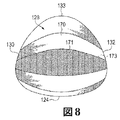
かかとキャビティ148および/または足先キャビティ150の3次元曲率は、ニット構成要素116の一体ニット構造によって形成することができる。たとえば、図8に示すように、かかと部128は、少なくとも2つのテーパー状区域170,171を含むことができる。テーパー状区域170,171は、破線で示されているように、大略的に横方向127に先細りになっている境界173を有することができる。テーパー状区域170,171は、それぞれ、複数のコースまたはステッチの列を有することができるが、連続的なコースは、異なる長さを有して、それによって、テーパー状の境界173を形成することができる。したがって、テーパー状区域170,171は、目の形状、縄編み卵形状、両凸形状または三日月形状を有することができる。
The three-dimensional curvature of the
また、テーパー状区域170の境界173は、3次元曲率を有するニット構成要素116を形成するように、一体ニット構造のテーパー状区域171の境界173に接合されている。このことは、接合された境界173に沿って、視覚的にはっきりと分かる歪みを作りだすことができる。その歪みは、ニット構成要素116の接合された境界173に沿って延びているいわゆるフルファッションのマークとすることができる。
Also, the
図8の実施形態においては、テーパー状区域がカラー133からベース部124まで延び、およびかかと部128の大部分が、それらのテーパー状区域を含むように、それぞれの境界に沿って接合されている複数のテーパー状区域がある。したがって、かかと部128の大部分は、3次元曲率を有することができる。しかし、3次元曲率をニット構成要素116に形成するために、ニット構成要素116が、ニット構成要素116のどの部分にも任意の数のテーパー状区域170,171を含むことができることは正しく認識されるであろう。また、テーパー状区域170,171は、ニット構成要素116上のどの適切な方向に向けても配置することができる。たとえば、足先部134は、同様に、テーパー状区域を含むことができるが、そのようなテーパー状区域は、例示的な実施形態においては、垂直方向129に先細りにすることができる。
In the embodiment of FIG. 8, tapered areas extend from the
舌革部136の湾曲領域143は、湾曲領域143に曲率を与える複数のテーパー状区域を含むこともできる。たとえば、湾曲領域143は、一緒に一体的に編まれて、境界197に沿って接合されているテーパー状区域193,195を含むことができる。このことは、接合された境界197に沿って、視覚的にはっきりと分かる歪みを作りだすことができる。その歪みは、ニット構成要素116の接合された境界197に沿って延びているいわゆるフルファッションのマークとすることができる。くわえて、上述したように、湾曲領域143内のコースは、2次元曲率を与えるように、共通区域151から放射状に広がることができる。
The
また、いくつかの実施形態において、足先部134は、足先部134の曲率を増加しやすくするように配列されている複数の開口部152を含むことができる。図示されている実施形態においては、複数の開口部152は、スルーホールから成る1つ以上の列を含むことができる。開口部152は、足先部134の当該区域におけるニット材料の量を減らすため、足先部134は、かかと部128に向かって後方に容易に湾曲することができる。
In some embodiments, the
ニット構成要素116は、アッパー120を組み立てる際に、一緒に接合されるように構成されている少なくとも2つの縁部140,142を追加的に含むことができる。第1の縁部140を、図5および図6に示すニット構成要素116のより大きな周辺縁部199の第1の長手方向部分とすることができることは正しく認識されるであろう。また、第2の縁部142を、周辺縁部199の第2の長手方向部分とすることができることも正しく認識されるであろう。縁部140,142は、周辺縁部199に沿った任意の適切な箇所に、および/またはニット構成要素116のどこにでも画成することができる。図5および図6に図示されているように、第1の縁部140は、舌革部136の湾曲領域143に沿って延びることができ、および足先部134に隣接して、横方向127において、ベース部124を部分的に貫通して延びることもできる。第2の縁部142は、概して横方向127において、足先部134に沿って湾曲することができ、およびギャップ139を部分的に画成するように、足先部134に沿って垂直方向129の下向きに延びることができる。第1の縁部140および第2の縁部142は、図4に示すように、ベース部124内に画成されている切り欠き部141で合流することも可能である。
The
上述したように、履物100はさらに、図1に図示されているクロージャー部材154を含むことができる。クロージャー部材154は、アッパー120を着用者の足に選択的に固定することができ、およびアッパー120を着用者の足から選択的に解放することができる。
As described above, the
図1に示すように、クロージャー部材154は、靴ひも155とすることができる。したがって、外側部130は、外側縁部135に沿って延びている列状に配置されているスルーホール等の1つ以上の外側クロージャー開口部156を含むことができる。内側部132は、内側縁部137に沿って延びている列状に配置されている同様の内側クロージャー開口部157を含むことができる。開口部156,157は、靴ひも155が、外側部130と内側部132との間で、交差し、ジグザグになり、および互い違いにできるように、靴ひも155を受け入れることができる。
As shown in FIG. 1, the
開口部156,157は、図1に示すスルーホールとは異なるように構成することができることは正しく認識されるであろう。たとえば、開口部156,157は、クロージャー部材を受け入れるように構成され、およびニット構成要素116に一体化されているか、またはニット構成要素116に取り外し可能に取り付けられているフープ、グロメット、および他の適当な形状構成によって画成することができる。
It will be appreciated that the
また、クロージャー部材154は、本開示の範囲から逸脱することなく、靴ひも155以外の構造物を含むことができることは正しく認識されるであろう。たとえば、クロージャー部材154は、ストラップ、留め金、パイルテープ、または、他の適当なクロージャー部材とすることができるであろう。
It will also be appreciated that the
さらに、図6に示すように、アッパー120は、ベース部124および/または側部126に結合されている少なくとも1つの伸張性ストランド158を含むことができる。ストランド158は、ベース部124および/または側部126のどの部分にも結合することができる。くわえて、ストランド158は、何らかの適当な方法で、ベース部124および/または側部126に結合することができる。たとえば、ストランド158は、説明されるように、ベース部124および側部126の一体ニット構造のコースおよび/またはウェール内に挿入することができる。したがって、ストランド158は、上述し、および図13および図14に図示されているストランド1132に一致することが可能である。また、ストランド158は、ベース部124および/または側部126の内側面121または外側面123に接着し、固定し、貫通させ、または他の方法で結合することもできる。
Further, as shown in FIG. 6, the upper 120 can include at least one
ストランド158、ニット構成要素116およびアッパー120は、2008年12月18日に出願され、2010年6月24日に特許文献1として公開されたDuaらの共同所有米国特許出願第12/338,726号明細書「Article of Footwear Having An Upper Incorporating A Knitted Component」と、2011年3月15日に出願され、2012年9月20日に特許文献2として公開されたHuffaらの米国特許出願第13/048,514号明細書「Article Of Footwear Incorporating A Knitted Component」とのうちの1つ以上の教示を包含することができ、(本願明細書において、まとめて「インレイストランド案件」と呼ぶ)これらの出願はともに、参照によってそれら全体が本願明細書に組み込まれるものとする。
The
ストランド158は、細長くて柔軟にすることができる。また、ストランド158は、少なくとも1つのヤーン、ケーブル、ワイヤ、糸、より糸、フィラメント、繊維、スレッド、ロープ等を含むことができる。また、ストランド158は、レーヨン、ナイロン、ポリエステル、ポリアクリル、絹、綿、カーボン、ガラス、アラミド(たとえば、パラアラミド繊維およびメタアラミド繊維)、超高分子量ポリエチレン、液晶ポリマー、銅、アルミニウム、鋼鉄またはその他の適当な材料から形成することができる。ストランド158に用いられる個々のフィラメントは、単一の材料(すなわち、単一成分フィラメント)または複数の材料(すなわち、複合フィラメント)から形成してもよい。同様に、異なるフィラメントを、異なる材料から形成してもよい。実施例として、ストランド158として用いられるヤーンは、それぞれ共通の材料から形成されているフィラメントを含んでもよく、それぞれ2つ以上の異なる材料から形成されているフィラメントを含んでもよく、または、それぞれ2つ以上の異なる材料から形成されているフィラメントを含んでもよい。同様の概念は、スレッド、ケーブル、ロープ等にも当てはまる。ストランド158の厚さ(直径)は、たとえば、約0.03ミリメートルから5ミリメートルの範囲内にすることができる。また、ストランド158は、実質的に円形の断面、卵形の断面、または、他の任意の適当な形状を有することができる。
The
実施例として、ストランド158は、破壊または引張強度が3.1キログラムで、重量が45texのボンデッドナイロン6.6から形成してもよい。また、ストランド158は、破壊または引張強度が6.2キログラムで、45texのボンデッドナイロン6.6から形成してもよい。さらなる実施例として、ストランド158は、内核を覆って保護する外鞘を有していてもよい。
As an example, the
いくつかの実施形態において、ストランド158は、固定長を有することができる(たとえば、伸長不能にすることができる)。また、いくつかの実施形態において、ストランド158は、弾性的に伸長可能にすることができる。
In some embodiments, the
くわえて、いくつかの実施形態において、ストランド158は、アッパー120のベース部124および/または側部126に付着し、接合し、または融着するように構成されている熱可塑性材料を含むことができる。たとえば、選択的な加熱は、ストランド158の材料を、ベース部124および/または側部126の材料に融着させることができる。その結果、2012年9月20日に公開され、および参照によって、その全体が本願明細書に組み込まれる特許文献2の教示に従って、ストランド158を含ませることができる。
In addition, in some embodiments, the
図6の実施形態に図示されているように、アッパー120は、内側部132と、ベース部124と、外側部130との間に連続的に延びている単一のストランド158を含むことができる。また、ストランド158は、1つ以上のターン159,160を含むこともできる。ターン159,160は、180度以上のターンとすることができる。具体的には、ストランド158は、外側縁部135に沿って列状に配置されている複数の外側ターン159を含むことができ、また、ストランド158は、内側縁部137に沿って列状に配置されている複数の内側ターンを含むことができる。また、ストランド158は、一組のターン159,160の間で直線状に延びることもできる。くわえて、ストランド158は、かかと部128に隣接して配置されている第1の末端部164を含むことができ、また、ストランド158は、足先部134に隣接して配置されている第2の末端部166を含むことができる。また、ストランド158は、外側部130および内側部132の間に交互に延びてジグザグになることも可能である。
As illustrated in the embodiment of FIG. 6, the upper 120 can include a
さらに、図6および図7に図示されているように、ニット構成要素116は、内側面121と外側面123との間に経路162を画成することができる。経路162は、何らかの適当な方法で画成することができる。たとえば、ストランド158がニット構成要素116内に挿入されている実施形態において、経路162は、ニット構成要素116の1つ以上のコースまたはウェールを通って画成することができる。また、いくつかの実施形態において、内側面121は、ニット材料から成る層によって画成することができ、また、外側面123は、ニット材料から成る別の層によって画成することができ、および複数のストランド、フィラメントまたは単一成分フィラメントは、これら3つの層の間に延びて、間隔(たとえば、いわゆる「スペーサーニット材料」)を形成することができる。これらの実施形態において、経路162は、ニット材料から成る層間および複数のスペーサーストランド間に画成することができる。追加的な実施形態において、内側面121および外側面123は、互いに縫い合わせて接続した面とすることができ、また、経路162は、それらの面の間に画成することができる。
Further, as illustrated in FIGS. 6 and 7, the
経路162は、アッパー120のどの部分にも横断して延びることができる。たとえば、図6の破線で示されているように、アッパー120は、複数の経路162を画成することができ、そして、各経路162は、外側部130と、ベース部124と、内側部132との間に連続的に延びることができる。図示されている実施形態において、各経路162は、経路162が、外側部130と、ベース部124と、内側部132との間で連続しているように、外側部130に部分的にわたって(外側経路)、ベース部124に部分的わたって(ベース部経路)、および内側部132に部分的にわたって(内側経路)延びている。しかし、1つ以上の経路162を、アッパー120の任意の部分に集中および離隔させることができることは正しく認識されるであろう。
The
図7に図示されているように、ストランド158は、外側部130と、ベース部124と、内側部132との間に延びるように、1つ以上の経路162内で長手方向に収容されて延びることができる。また、ストランド158のターン159,160は、経路162から露出させることができる。
As shown in FIG. 7, the
外側ターン159は、外側クロージャー開口部156のそれぞれ1つの周りに少なくとも部分的に延びることができ、また、内側ターン160は、内側クロージャー開口部157のそれぞれ1つの周りに少なくとも部分的に延びることができる。さらに、図1に示すように、外側クロージャー開口部156と外側ターン159とから成るそれぞれのペア内に靴ひも155を受け入れることができ、また、内側クロージャー開口部157と内側ターン160とから成るそれぞれのペア内にも靴ひも155を受け入れることができる。換言すれば、外側ターン159と外側クロージャー開口部156とから成る各組合せは、靴ひも155を協働して受け入れて支持することができ、また、内側ターン160と内側クロージャー開口部157とから成る各組合せも、靴ひも155を受け入れて支持することができる。
The outer turns 159 can extend at least partially around each one of the
いくつかの実施形態において、ストランド158は、それぞれの経路162内に、緩くかつ可動的に受け入れることができる。たとえば、ストランド158は、経路162を通って長手方向に滑動することができる。その結果、図9に図示されているように、ターン159,160は、それぞれのクロージャー開口部156,157まで近づけて引っ張ることができる。追加的な実施形態においては、ストランド158の第1の末端部164および/または第2の末端部166は、ストランド158の残りの部分が、ベース部124、外側部130および内側部132に対して移動可能な状態のままで、ベース部124に固定(たとえば、融着)することができる。さらに追加的な実施形態においては、末端部164,166間のストランド158の部分を、ベース部124、外側部130および内側部132に融着、または他の方法で固定することができる。
In some embodiments, the
したがって、靴ひも155に張力を加えても、ストランド158の張力を同様に増加させることができる。たとえば、図10に図示されているように、靴ひも155が緩められて、非固定位置にある場合、ストランド158の張力が比較的小さくなっている可能性があり、それによって、アッパー120を着用者の足の周りに緩くフィットさせることが可能である。しかし、矢印174,175で示すように、靴ひも155が引っ張られて張力が加えられると、靴ひも155がターン159,160をたぐり寄せて、ストランド158の張力を増加させる可能性がある。その結果として、ストランド158は、図11の矢印176,177,178,179によって示すように、アッパー120を着用者の足の近くまで引っ張って合わせることができる。
Therefore, even if tension is applied to the
図10および図11に示す実施形態においては、ストランド158が、着用者の足の底部のさまざまな区域に対する支持をもたらすことができることは正しく認識されるであろう。たとえば、ストランド158は、着用者の足のアーチの底面に配置されるように構成されているアーチ領域167上に配置することができる。したがって、アーチ領域167内のストランド158は、特に、ストランド158が靴ひも155によって張力を加えられている場合、着用者のアーチを支持することができる。
It will be appreciated that in the embodiment shown in FIGS. 10 and 11, the
図示されている実施形態においては、そのような足に対する支持をもたらすために、アッパー120が単一の連続ストランド158のみを含むことができることも正しく認識されるであろう。したがって、アッパー120の部材数を比較的少なくすることができ、およびアッパー120を効率的な方法で構成することができる。
It will also be appreciated that in the illustrated embodiment, the upper 120 can include only a single
履物の組立て
次に、例示的な実施形態に従って、履物100、ニット構成要素116およびアッパー120の組立てについて説明する。明確にするために、ニット構成要素116およびストランド158は、図5および図6に示す分解状態に形成されていると仮定する。
Assembling Footwear The assembly of
アッパー120の組立てに関する例示的な実施形態を始めるにあたり、外側部130および内側部132を、図4に示す位置に向かって上方へ移動させる(折り曲げる)ことができる。次に、湾曲領域143がギャップ139を実質的に塞ぐとともに、長手方向領域145がスロート131を実質的に塞ぐように、舌革部136を上方へ巻き上げることができる。したがって、第1の縁部140および第2の縁部142を互いに直接近接させて配置することができる。次いで、第1の縁部140および第2の縁部142を縫い目144で接合することができる。
To begin the exemplary embodiment for assembling the upper 120, the
第1の縁部140および第2の縁部142は、任意の適当な方法で、縫い目144において接合することができる。たとえば、第1の縁部140および第2の縁部142は、縫製、接着、テープ、ボンディング、溶接、ファスナーまたは他の適切な留め具を用いて接合することができる。
The
いくつかの実施形態において、縫い目144は、図1〜図3に示すように、縫い目146とともに縁部140,142を縫い合わせることによって形成することができる。上述したように、アッパー120は、複数のステッチを有するニット要素とすることができるが、縫い目146は、ニット構成要素116のステッチから独立させることができることは正しく認識されるであろう。換言すれば、縫い目146は、ニット構成要素116が編まれた後に取り付けられる1つ以上のスレッド、ヤーン、ケーブルまたはその他のストランドを用いて形成することができる。また、縫い目146は、ジグザグ縫いまたは他の適当なステッチとすることもできる。くわえて、縁部140,142は、縫い目144で当接することができる。たとえば、縁部140,142は、突き合わせジョイントを形成することができ、または、縁部140,142は、縫い目144を形成するように部分的に重ねることができる。くわえて、縁部140,142は、縫い目144における縁部140,142間の接着ビードまたは他の材料を用いて、縫い目144においてわずかに離間させることができる。
In some embodiments, the
また、縫い目144は、ニット構成要素116の適当などの部分にもわたって延びることができる。たとえば、図3の実施形態において、縫い目144は、足先部134に隣接してベース部124に配置された第1の末端部147を含むことができる。また、縫い目144は、外側縁部135、足先部134および舌革部136の接合部に第2の末端部149を含むこともできる。また、縫い目144は、いくつかの実施形態において、第1および第2の末端部147,149間に連続的に延びることができる。たとえば、縫い目144は、第1の末端部147から内側部132に向かって大略的に横方向127にベース部124にわたって延びている第1の部分181を含むことができる。また、縫い目144は、内側部132にわたって、および足先部134に隣接して大略的に垂直方向129に延びている第2の部分183も含むことができる。さらに、縫い目144は、外側部130に向かって大略的に横方向に延び、および第2の末端部149に向かって後方に湾曲している第3の部分185を含むことができる。したがって、縫い目144は、着用者の足の下から、着用者の足先の内側区域の周りを通って、着用者の足先の上の区域まで延びるように、端部147,149間に連続的に延びることができる。
The
また、ニット構成要素116には、任意の数の縫い目144が有る可能性がある。たとえば、図3の実施形態に図示されているように、アッパー120のニット構成要素116に、図1〜図3に示すような3次元形状を与えるために必要な唯一の縫い目144がある可能性がある。このことは、製造を容易にすることができ、およびアッパー120の組立てに必要な時間を短縮することができる。
Also, the
また、縫い目144は、かかと部128がシームレスになるように、かかと部128から離間させることができる。その結果、かかと部128が着用者のかかと上でずれた場合でも、比較的滑らかでシームレスのかかと部128は、着用者のかかとに対してすれて、着用者に不快感を与えることがほとんどない。
Also, the
その後、上述したように、靴ひも155を外側開口部156および内側開口部157および外側ターンおよび内側ターン159,160に通すことができる。次いで、ソール構造110をアッパー120に取り付けることができる。具体的には、ミッドソール112を、ベース部124の外側面123に取り付けることができ、また、アウトソール114を、ミッドソール112に取り付けることができる。追加的な実施形態においては、追加的な中敷きを、ベース部124の内側面121を覆って挿入することができ、および/または該内側面に取り付けることができる。
Thereafter, as described above, the
ニット構成要素およびアッパーの追加的な実施形態
アッパー220のニット構成要素116の追加的な実施形態を図12に示す。ニット構成要素116およびアッパー220は、説明されている場合を除いて、上述したニット構成要素116およびアッパー120と実質的に同様なものにすることができる。
Additional Embodiments of Knit Component and Upper Additional embodiments of the
アッパー220は、上述した実施形態と同様に、内側部232、ベース部224および外側部230にわたって互い違いに延びているストランド258を含むことができる。また、ストランド258は、1つ以上の経路262を通って延びることもできる。しかし、経路262は、内側部232および外側部230上に画成することができ、また、経路262は、ベース部224から離間させることができる。
The upper 220 can include
したがって、ベース部224を横切って延びているストランド258の長手方向部分は、経路262から露出させることができる。また、ストランド258のそれらの部分は、ベース部224から取り外すことができ、および分離することができる。したがって、いくつかの実施形態において、ストランド258のそれらの部分は、ソール構造110に自由に直接取り付け可能である。
Accordingly, the longitudinal portion of the
さらに、図12に示すように、いくつかの実施形態において、経路262は、ストランド258のターンが、図1〜図6に示す露出されているターン159,160とは違って、経路262内に埋め込まれて包囲されるように、V字状にすることができる。
In addition, as shown in FIG. 12, in some embodiments, the
ニット構成要素およびアッパーを形成するための例示的な編みプロセス
ニット構成要素116は、任意の適当な方向に編むことができる。たとえば、ニット構成要素116は、カラー133において、かかと部128から形成することができ、また、ニット構成要素116は、足先部134に向かって大略的に長手方向125に伸びていくように形成することができる。足先キャビティ150は、舌革部136の前に形成することができる。そしてその後、舌革部136を形成することができる。また、ニット構成要素116の3次元的に湾曲したキャビティおよび2次元的に湾曲した部分(たとえば、かかとキャビティ148、足先キャビティ150、湾曲領域143および/またはその他の区域)を、編みプロセス中に一体的に形成できることは正しく認識されるであろう。具体的には、境界173,197におけるステッチは、後続のステッチのコースが追加される際に、それぞれの針によって保持することができ、境界173,197において保持されたステッチは、境界173,197全域でそれぞれのステッチに編み込むことができる。また、編みプロセス中に、ストランド158を挿入することができる。また、このプロセスは、横編み機等の何らかの適当な機械で完了させることができる。
Exemplary Knitting Process for Forming Knit Component and
次に、図15〜図23を参照して、ストランド158を備えたニット構成要素116を形成するための例示的な自動編みプロセスについて説明する。説明のため、横編みプロセスおよび横編み機について説明するが、ニット構成要素116およびストランド158は、本開示の範囲から逸脱することなく、他の方法でも形成することができる。したがって、ニット構成要素116およびストランド158は、2012年9月20日に公開され、および参照によって、その全体が本願明細書に組み込まれる、特許文献2の教示に従って形成することができる。
An exemplary automatic knitting process for forming a
図15を参照すると、さまざまな針1202、レール1203、標準フィーダー1204およびコンビネーションフィーダー1220を含む編み機1200の一部が描かれている。コンビネーションフィーダー1220がレール1203の前側に固定されているのに対して、標準フィーダー1204は、レール1203の後側に固定されている。ヤーン1206は、コンビネーションフィーダー1220を通っており、また、ヤーン1206の端部は、給糸先端部1246から外部に延びている。ヤーン1206が描かれているが、他のどのようなストランド(例、フィラメント、スレッド、ロープ、帯、ケーブル、鎖またはヤーン)がコンビネーションフィーダー1220を通過してもよい。別のヤーン1211が標準フィーダー1204を通過して、ニット構成要素1260の一部を形成し、ニット構成要素1260の最上コースを形成しているヤーン1211のループが、針1202の端部に設けられたフックによって保持されている。
Referring to FIG. 15, a portion of a
本願明細書において説明されている編みプロセスは、ニット構成要素1260またはニット構成要素1260の一部の形成に関するものである。したがって、ニット構成要素1260のその部分は、図1〜図6に関連して上述したベース部124、かかと部128、外側部130、内側部132、足先部134および/または舌革部136に対応することができる。説明のため、図面では、ニット構造を例示できるように、ニット構成要素1260の比較的小さな区画のみが図示されている。また、編み機1200およびニット構成要素1260のさまざまな要素の縮尺または比率は、編みプロセスをよりよく例示するために拡大されている可能性がある。
The knitting process described herein relates to the formation of a
ここで図16を参照すると、標準フィーダー1204は、レール1203に沿って移動し、ヤーン1211からニット構成要素1260内に新たなコースが形成されている。より具体的には、針1202は、前のコースのループを通してヤーン1211の区画を引っ張り、それによって新たなコースを形成する。したがって、標準フィーダー1204を針1202に沿って移動させることにより、ニット構成要素1260にコースを追加することができ、それによって、針1202がヤーン1211を操作して、ヤーン1211から追加のループを形成することを可能にしている。
Referring now to FIG. 16,
編みプロセスに関して続けると、図17に示すように、フィーダーアーム1240は、ここでは、後退位置から延伸位置に並進している。延伸位置では、フィーダーアーム1240は、キャリア1230から下方へ延びて、給糸先端部1246を、(a)針1202の間の中心になる、および(b)針床の交差部の下になる位置に配置している。
Continuing with the knitting process, as shown in FIG. 17, the
次に図18を参照すると、コンビネーションフィーダー1220は、レール1203に沿って移動し、ヤーン1206が、ニット構成要素1260のループ間に位置している。すなわち、ヤーン1206は、いくつかのループの前かつ他のループの背後に交互パターンで配置されている。また、ヤーン1206は、ある針床1201からの針1202によって保持されているループの前に配置され、およびヤーン1206は、他方の針床からの針1202によって保持されているループの背後に配置されている。フィーダーアーム1240は、ヤーン1206を針床の交差部の下の区域に挿入するために、延伸位置にとどまっていることに留意する。これにより、ヤーン1206が、図16の標準フィーダー1204によって直前に形成されたコース内に効果的に配置される。
Referring now to FIG. 18, the
ニット構成要素1260へのヤーン1206の挿入を完了するために、図19に図示するように、標準フィーダー1204は、レール1203に沿って移動して、ヤーン1211から新たなコースを形成する。新たなコースを形成することによって、ヤーン1206は、ニット構成要素1260の構造内に効果的に編み込まれるか、または、その他の形で該構造に一体化される。この段階では、フィーダーアーム1240も延伸位置から後退位置に並進していてもよい。
To complete the insertion of the
図18および図19は、レール1203に沿ったフィーダー1204および1220の個別の動きを示している。すなわち、図18は、レール1203に沿ったコンビネーションフィーダー1220の第1の動きを示し、図19は、レール1203に沿った標準フィーダー1204の第2のその後の動きを示している。多くの編みプロセスでは、フィーダー1204および1220を同時に効率的に移動させて、ヤーン1206を挿入し、およびヤーン1211から新たなコースを形成する。しかし、ヤーン1211からの新たなコースの形成前にヤーン1206を配置するために、コンビネーションフィーダー1220は、標準フィーダー1204に先立って移動するか、または、該標準フィーダーの前方に移動する。
18 and 19 show the individual movement of the
上記説明で概説した一般的な編みプロセスは、図1〜図6のストランド158を、アッパー120のベース部124、外側部130および/または内側部132に配置することができる態様の実施例を提供する。より具体的には、フィーダーアーム1240の往復運動のため、ストランド158は、新たなコースの形成前に、以前に形成されたコース内に配置してもよい。
The general knitting process outlined in the above description provides an example of how the
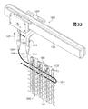
編みプロセスに関して続けると、図20に示すように、フィーダーアーム1240は、ここでは、後退位置から延伸位置に並進している。そして、図21に示すように、コンビネーションフィーダー1220がレール1203に沿って移動して、ヤーン1206が、ニット構成要素1260のループ間に配置される。これにより、ヤーン1206は、図19の標準フィーダー1204で形成されたコース内に効果的に配置される。ニット構成要素1260へのヤーン1206の挿入を完了するために、図22に図示するように、標準フィーダー1204は、レール1203に沿って移動して、ヤーン1211から新たなコースを形成する。新たなコースを形成することにより、ヤーン1206は、ニット構成要素1260の構造内に効果的に編み込まれるか、またはその他の形で該構造に一体化される。この段階では、フィーダーアーム1240も延伸位置から後退位置に並進していてもよい。
Continuing with the knitting process, as shown in FIG. 20, the
図22を参照すると、ヤーン1206は、2つのインレイ区画の間にループ1214を形成している。図1〜図6のターン159,160の説明においては、ストランド158が経路162を出てから別の経路162に入り、それによって、ターン159,160を形成していることに留意されたい。ループ1214は、同様の方法で形成することができる。すなわち、ループ1214は、ヤーン1206がニット構成要素1260のニット構造を出てから該ニット構造に再進入する箇所に形成される。
Referring to FIG. 22,
図23を参照すると、コンビネーションフィーダー1220は、後退位置にある間はレール1203に沿って移動し、後退位置にある間は、ニット構成要素1260のコースを形成する。したがって、後退位置と延伸位置との間でフィーダーアーム1240を往復動させることにより、コンビネーションフィーダー1220は、編み、タック編み、浮き編みおよび挿入のためにヤーン1206を供給することができる。
Referring to FIG. 23, the
以下の説明および添付図面は、ニット構成要素およびニット構成要素の製造に関するさまざまな概念を開示している。ニット構成要素は、さまざまな製品に利用してもよいが、それらのニット構成要素のうちの1つを組み込んだ履物製品は、以下において実施例として開示されている。 The following description and the accompanying drawings disclose various concepts related to the manufacture of knit components and knit components. While the knitted component may be utilized in a variety of products, footwear products incorporating one of those knitted components are disclosed as examples below.
実施形態に関する上記の説明は、例示および説明のために記載されている。包括的であること、または、本開示を制限することは意図されていない。特定の実施形態の個々の要素または形状構成は、一般的に、その具体的な実施形態に限定されないが、適用可能な場合は、置換え可能であり、および具体的な図示または説明がなされていない場合であっても、選択された実施形態において用いることができる。同じものは、多くの方法で変更してもよい。そのような変更は、本開示からの逸脱と見なすべきではなく、また、そのようなすべての変更は、本開示の範囲内に含まれることが意図されている。 The above description of the embodiments has been set forth for purposes of illustration and description. It is not intended to be exhaustive or to limit the present disclosure. Individual elements or configurations of a particular embodiment are generally not limited to that particular embodiment, but can be substituted where applicable and are not specifically illustrated or described. Even so, it can be used in selected embodiments. The same may be changed in many ways. Such modifications are not to be regarded as a departure from the present disclosure, and all such modifications are intended to be included within the scope of the present disclosure.
Claims (60)
一体ニット構造を有するニット構成要素であって、
前記ソール構造に隣接して配置されるように構成されたベース部と、
前記ベース部の両端部から延びているかかと部および足先部と、
前記ベース部の両側部から延びている内側部および外側部であって、前記内側部と前記外側部との間にスロート区域を画成するように協働する、内側部および外側部と、
前記ベース部から延び、前記スロート区域内に配置されるように構成されている舌革部であって、前記内側部および前記外側部の少なくとも一方から分離されている舌革部と、
を備えるニット構成要素と、
前記ニット構成要素の第1の縁部と、
縫い目で前記第1の縁部に結合されて、前記ベース部、前記かかと部、前記足先部、前記内側部および前記外側部に、前記足を受け入れるように構成される空洞を協働して画成させるように構成された前記ニット構成要素の第2の縁部と、を備えるアッパー。 An upper for a footwear product configured to be connected to a sole structure and configured to receive a foot,
A knit component having an integral knit structure,
A base portion configured to be disposed adjacent to the sole structure;
A heel part and a foot part extending from both ends of the base part;
An inner portion and an outer portion extending from opposite sides of the base portion, the inner and outer portions cooperating to define a throat area between the inner portion and the outer portion;
And extending from said base portion, said a tongue portion that is configured to be placed in the throat zone, the inner part and the tongue part are separated at least one pressurized et content of the outer portion,
A knit component comprising:
A first edge of the knit component;
Coupled to the first edge at a seam, cooperating a cavity configured to receive the foot in the base portion, the heel portion, the toe portion, the inner portion and the outer portion; An upper comprising: a second edge of the knit component configured to define.
前記ソール構造に隣接して配置されるように構成されたベース部と、
前記ベース部の両端部から延びているかかと部および足先部と、
前記ベース部の両側部から延びている内側部および外側部であって、前記内側部と前記外側部との間にスロート区域を画成するように協働する、内側部および外側部と、
前記ベース部から延び、前記スロート区域内に配置されるように構成されている舌革部であって、前記内側部および前記外側部の少なくとも一方からは分離されている舌革部と、
を有するように前記ニット構成要素を編むことと、
前記ニット構成要素の第1の縁部と、前記ニット構成要素の第2の縁部とを縫い目で結合して、前記ベース部、前記かかと部、前記足先部、前記内側部および前記外側部に、足を受け入れるように構成される空洞を協働して画成させることと、を含む方法。 A method of manufacturing a knitted component for footwear products configured to be connected to a sole structure comprising:
A base portion configured to be disposed adjacent to the sole structure;
A heel part and a foot part extending from both ends of the base part;
An inner portion and an outer portion extending from opposite sides of the base portion, the inner and outer portions cooperating to define a throat area between the inner portion and the outer portion;
A tongue portion extending from the base portion and configured to be disposed in the throat area, wherein the tongue portion is separated from at least one of the inner portion and the outer portion;
Knitting the knit component to have
The base portion, the heel portion, the toe portion, the inner portion, and the outer portion are joined by stitching the first edge portion of the knit component and the second edge portion of the knit component. Co-defining a cavity configured to receive a foot .
前記ソール構造に隣接して配置されるように構成されているベース部を有するニット構成要素であって、前記ベース部が、前記ニット構成要素の内側面および外側面を画成し、前記ベース部が、前記内側面と前記外側面との間にベース部経路を画成するニット構成要素と、
前記ベース部経路を通って延びている伸張性ストランドと、
を備えるアッパー。 An upper for a footwear product configured to be connected to a sole structure and configured to receive a foot,
A knit component having a base portion configured to be disposed adjacent to the sole structure, wherein the base portion defines an inner surface and an outer surface of the knit component; A knit component that defines a base path between the inner surface and the outer surface;
An extensible strand extending through the base path;
Upper equipped with.
ように構成されている、請求項38に記載のアッパー。 The side includes an opening, the turn extends at least partially around the opening, and the opening and the turn are configured to cooperatively receive and support the closure element. 40. The upper of claim 38.
前記ソール構造に隣接して配置されるように構成されているベース部を有するニット構成要素を編むことであって、前記ベース部が、前記ニット構成要素の内側面および外側面を画成し、前記ベース部が、前記内側面と前記外側面との間にベース部経路を画成することと、
前記ベース部経路を通して伸張性ストランドを延ばすことと、
を含む方法。 A method of manufacturing an upper configured to be connected to a sole structure and configured to be worn on a foot, comprising:
Knitting a knit component having a base portion configured to be disposed adjacent to the sole structure, the base portion defining an inner surface and an outer surface of the knit component; The base portion defining a base portion path between the inner surface and the outer surface;
Extending an extensible strand through the base path;
Including methods.
アッパーであって、
一体ニット構造を有し、前記ソール構造に隣接して配置されるように構成されているベース部を有するニット構成要素であって、前記ベース部が、前記ニット構成要素の内側面および外側面を画成し、前記ベース部が、前記内側面と前記外側面との間にベース部経路を画成するニット構成要素と、
前記ベース部経路を通って延びる伸張性ストランドと、
を備えるアッパーと、
を備える履物製品。 Sole structure,
Upper,
A knit component having a unitary knit structure and having a base portion configured to be disposed adjacent to the sole structure, wherein the base portion includes an inner surface and an outer surface of the knit component. A knit component defining and defining the base portion path between the inner side surface and the outer side surface;
An extensible strand extending through the base path;
An upper comprising:
Footwear products comprising.
Applications Claiming Priority (3)
| Application Number | Priority Date | Filing Date | Title |
|---|---|---|---|
| US13/783,900 | 2013-03-04 | ||
| US13/783,900 US9848672B2 (en) | 2013-03-04 | 2013-03-04 | Article of footwear incorporating a knitted component with integrally knit contoured portion |
| PCT/US2014/019548 WO2014137826A1 (en) | 2013-03-04 | 2014-02-28 | Article of footwear incorporating a knitted component with integrally knit contoured portion |
Publications (3)
| Publication Number | Publication Date |
|---|---|
| JP2016516458A JP2016516458A (en) | 2016-06-09 |
| JP2016516458A5 JP2016516458A5 (en) | 2016-09-23 |
| JP6399524B2 true JP6399524B2 (en) | 2018-10-03 |
Family
ID=50678261
Family Applications (1)
| Application Number | Title | Priority Date | Filing Date |
|---|---|---|---|
| JP2015561475A Active JP6399524B2 (en) | 2013-03-04 | 2014-02-28 | Footwear products incorporating knit components with integrated knit contours |
Country Status (10)
| Country | Link |
|---|---|
| US (1) | US9848672B2 (en) |
| EP (1) | EP2964044B1 (en) |
| JP (1) | JP6399524B2 (en) |
| KR (1) | KR101844640B1 (en) |
| CN (2) | CN107348615B (en) |
| AR (1) | AR094988A1 (en) |
| BR (1) | BR112015021759A8 (en) |
| HK (1) | HK1214098A1 (en) |
| TW (1) | TWI516217B (en) |
| WO (1) | WO2014137826A1 (en) |
Families Citing this family (48)
| Publication number | Priority date | Publication date | Assignee | Title |
|---|---|---|---|---|
| US9498023B2 (en) | 2012-11-20 | 2016-11-22 | Nike, Inc. | Footwear upper incorporating a knitted component with sock and tongue portions |
| US9848672B2 (en) | 2013-03-04 | 2017-12-26 | Nike, Inc. | Article of footwear incorporating a knitted component with integrally knit contoured portion |
| US9936757B2 (en) * | 2013-03-04 | 2018-04-10 | Nike, Inc. | Article of footwear incorporating a knitted component with integrally knit contoured portion |
| DE102013207156A1 (en) | 2013-04-19 | 2014-10-23 | Adidas Ag | Shoe, in particular a sports shoe |
| US11666113B2 (en) * | 2013-04-19 | 2023-06-06 | Adidas Ag | Shoe with knitted outer sole |
| DE102013207163B4 (en) | 2013-04-19 | 2022-09-22 | Adidas Ag | shoe upper |
| DE102013207155B4 (en) | 2013-04-19 | 2020-04-23 | Adidas Ag | Shoe upper |
| US10299531B2 (en) * | 2013-05-14 | 2019-05-28 | Nike, Inc. | Article of footwear incorporating a knitted component for a heel portion of an upper |
| US9538803B2 (en) * | 2013-05-31 | 2017-01-10 | Nike, Inc. | Method of knitting a knitted component for an article of footwear |
| BR112015030561A2 (en) * | 2013-06-17 | 2017-07-25 | Shima Seiki Mfg | upper and method for producing a upper |
| JP6288743B2 (en) * | 2013-09-13 | 2018-03-07 | ナイキ イノヴェイト シーヴィーNike Innovate C.V. | Footwear products incorporating knit components with integrated knit contours |
| DE102014202432B4 (en) | 2014-02-11 | 2017-07-27 | Adidas Ag | Improved football boot |
| US9920461B2 (en) * | 2014-03-04 | 2018-03-20 | Knitmasters, Llc | Knitted shoe components and methods of making the same |
| US10383388B2 (en) | 2014-03-07 | 2019-08-20 | Nike, Inc. | Article of footware with upper incorporating knitted component providing variable compression |
| US9510637B2 (en) * | 2014-06-16 | 2016-12-06 | Nike, Inc. | Article incorporating a knitted component with zonal stretch limiter |
| TW201607448A (en) * | 2014-06-30 | 2016-03-01 | 島精機製作所股份有限公司 | Shoe upper |
| US9192204B1 (en) * | 2014-09-30 | 2015-11-24 | Nike, Inc. | Article of footwear upper incorporating a textile component with tensile elements |
| US9078488B1 (en) | 2014-09-30 | 2015-07-14 | Nike, Inc. | Article of footwear incorporating a lenticular knit structure |
| US10822728B2 (en) | 2014-09-30 | 2020-11-03 | Nike, Inc. | Knitted components exhibiting color shifting effects |
| US9375046B2 (en) | 2014-09-30 | 2016-06-28 | Nike, Inc. | Article of footwear incorporating a knitted component with inlaid tensile elements and method of assembly |
| DE102014220087B4 (en) | 2014-10-02 | 2016-05-12 | Adidas Ag | Flat knitted shoe top for sports shoes |
| TW201632094A (en) * | 2014-12-25 | 2016-09-16 | 島精機製作所股份有限公司 | Method for knitting and producing footwear and footwear |
| JP6764409B2 (en) * | 2015-01-16 | 2020-09-30 | ナイキ イノベイト シーブイ | Footwear products |
| TWM534533U (en) * | 2015-05-29 | 2017-01-01 | 耐基創新公司 | Footwear manufacturing with a flat pattern upper |
| JP2018532461A (en) * | 2015-09-08 | 2018-11-08 | エイヴェリー デニソン リテール インフォメーション サービシズ リミテッド ライアビリティ カンパニー | Shrink shoe or sock device |
| US9888742B2 (en) * | 2015-09-11 | 2018-02-13 | Nike, Inc. | Article of footwear with knitted component having plurality of graduated projections |
| USD794313S1 (en) * | 2015-12-01 | 2017-08-15 | Nike, Inc. | Shoe upper |
| CN112890350B (en) * | 2016-01-15 | 2023-02-17 | 耐克创新有限合伙公司 | Method of manufacturing a footwear upper with a knitted component |
| CN105544080B (en) * | 2016-02-19 | 2017-09-29 | 新科技针织有限公司 | Shaping knitting shoe cover and its method for weaving, shoe body |
| EP4026936A1 (en) | 2016-04-01 | 2022-07-13 | NIKE Innovate C.V. | Shoe upper having a knitted component with a strap |
| CN109068785B (en) * | 2016-04-25 | 2021-04-13 | 株式会社岛精机制作所 | Method for manufacturing shoe and shoe |
| US10624412B2 (en) * | 2016-06-01 | 2020-04-21 | Nike, Inc. | Printing over stitching |
| CN109714998B (en) * | 2016-08-12 | 2021-11-02 | 耐克创新有限合伙公司 | Article having a first section with a first yarn and a second yarn |
| US10349702B2 (en) * | 2016-09-09 | 2019-07-16 | Nike, Inc. | Knitting of multiple uppers on a machine |
| US10844526B2 (en) * | 2016-10-23 | 2020-11-24 | Nike, Inc. | Upper including a knitted component having structures with apertures extending from a surface |
| GB2571231B (en) | 2016-11-09 | 2020-03-25 | Nike Innovate Cv | Textiles and articles, and processes for making the same |
| US10316441B2 (en) | 2016-12-16 | 2019-06-11 | The North Face Apparel Corp. | Footwear article including circular knit structures |
| USD824644S1 (en) | 2016-12-16 | 2018-08-07 | The North Face Apparel Corp. | Footwear article |
| US11408104B2 (en) | 2016-12-16 | 2022-08-09 | The North Face Apparel Corp. | Footwear article including circular knit structures |
| CN108338453A (en) * | 2017-01-25 | 2018-07-31 | 清远广硕技研服务有限公司 | Article of footwear and its knitting vamp and manufacturing method |
| TWI632265B (en) * | 2017-03-10 | 2018-08-11 | 薩摩亞商紘織國際有限公司 | Method for integrally weaving an extended shoe with a flat knitting machine |
| CN107157017B (en) * | 2017-06-30 | 2023-04-21 | 信泰(福建)科技有限公司 | Rope-embedded integrated vamp and knitting process thereof |
| US10791791B2 (en) | 2018-01-20 | 2020-10-06 | Nike, Inc. | Articles of footwear reinforced with high tenacity yarn |
| US10731279B2 (en) | 2018-01-20 | 2020-08-04 | Nike, Inc. | Knitted components reinforced with high tenacity yarn |
| FR3082103B1 (en) | 2018-06-08 | 2020-08-28 | Decathlon Sa | METHOD OF MANUFACTURING A SHOE, AND SHOE LIKELY TO BE OBTAINED BY LEDIT PROCEDE |
| IT201900007821A1 (en) * | 2019-06-03 | 2020-12-03 | Lonati Spa | UPPER STRUCTURE AND PROCEDURE FOR THE PRODUCTION OF AN UPPER STRUCTURE. |
| JPWO2022137407A1 (en) * | 2020-12-23 | 2022-06-30 | ||
| WO2023069764A2 (en) * | 2021-10-22 | 2023-04-27 | Nike Innovate C.V. | Articles of footwear with knitted components and methods of manufacturing the same |
Family Cites Families (186)
| Publication number | Priority date | Publication date | Assignee | Title |
|---|---|---|---|---|
| US601192A (en) | 1898-03-22 | Tongue for boots or shoes | ||
| US336913A (en) | 1886-03-02 | graff | ||
| US1215198A (en) | 1916-09-21 | 1917-02-06 | Joseph Rothstein | Cushion instep-raiser. |
| US1359377A (en) | 1919-03-29 | 1920-11-16 | Michael J Hollenbeck | One-piece slipper |
| US1597934A (en) | 1922-10-10 | 1926-08-31 | Edwin B Stimpson | Stocking |
| US1902780A (en) | 1930-04-11 | 1933-03-21 | Holden Knitting Co | Knitted lining for rubber footwear and method of making same |
| US1910251A (en) | 1931-12-09 | 1933-05-23 | Reliable Knitting Works | Knitted foot covering and method of making the same |
| US1888172A (en) | 1932-06-06 | 1932-11-15 | Reliable Knitting Works | Knitted footwear and method of making the same |
| US2001293A (en) | 1934-02-10 | 1935-05-14 | Wilson Wallace | Knitted stocking foot protector |
| US2047724A (en) | 1934-07-12 | 1936-07-14 | Louis G Zuckerman | Knitted article and method of making same |
| US2147197A (en) | 1936-11-25 | 1939-02-14 | Hood Rubber Co Inc | Article of footwear |
| US2330199A (en) | 1939-05-22 | 1943-09-28 | Basch Olive Holmes | Knitted article |
| GB538865A (en) | 1939-11-18 | 1941-08-20 | Harold Edmund Brew | Improvements relating to knitted fabrics and manufactured knitted articles |
| US2314098A (en) | 1941-04-26 | 1943-03-16 | Mary C Mcdonald | Method of making shoes |
| US2343390A (en) | 1941-11-26 | 1944-03-07 | United Shoe Machinery Corp | Method of stiffening shoes |
| US2400692A (en) | 1943-03-24 | 1946-05-21 | Theotiste N Herbert | Foot covering |
| US2440393A (en) | 1944-08-18 | 1948-04-27 | Frank W Clark | Process of making last-fitting fabric uppers |
| US2569764A (en) | 1946-07-25 | 1951-10-02 | Boyd Welsh Inc | Initially soft stiffenable material |
| US2495984A (en) | 1947-11-25 | 1950-01-31 | Edna M Roy | Sole with detachable upper |
| US2494617A (en) | 1949-06-27 | 1950-01-17 | Hogan Rose | One-piece foot covering |
| US2608078A (en) | 1950-01-04 | 1952-08-26 | Munsingwear Inc | Foundation garment and element therefor |
| US2586045A (en) | 1950-06-23 | 1952-02-19 | Hoza John | Sock-type footwear |
| US2654965A (en) * | 1950-09-01 | 1953-10-13 | Jervis H Sloan | Shoe with insole exposable to view |
| US2641004A (en) | 1950-12-26 | 1953-06-09 | David V Whiting | Method for producing knitted shoe uppers of shrinkable yarn |
| US2675631A (en) | 1951-02-13 | 1954-04-20 | Doughty John Carr | Footwear article of the slipper-sock type |
| DE870963C (en) | 1951-03-13 | 1953-03-19 | Georg Hofer | Strap for boots, especially for ski boots |
| DE1084173B (en) | 1954-09-18 | 1960-06-23 | Walter Geissler | Shoe upper |
| US2974427A (en) | 1958-08-01 | 1961-03-14 | William C Wolff | Shoe construction comprising an integral upper and insole |
| US2994322A (en) | 1959-01-12 | 1961-08-01 | Charles C Cullen | Protective supporter |
| US3289330A (en) * | 1964-03-05 | 1966-12-06 | Us Shoe Corp | Blank for a moccasin shoe |
| US3378940A (en) * | 1964-06-22 | 1968-04-23 | R J Potvin Shoe Company Inc | Moccasin shoe and blank therefor |
| GB1223285A (en) | 1967-08-29 | 1971-02-24 | Onitsuka Co | Improvements in shoes |
| DE6944404U (en) | 1969-11-14 | 1970-02-19 | Justus Rieker Co Dr | INNER SHOE FOR BOOTS, IN PARTICULAR SKI BOOTS MADE OF PLASTIC |
| US3618235A (en) * | 1970-01-19 | 1971-11-09 | George R Cary Jr | Adjustable footwear |
| US3704474A (en) | 1971-10-21 | 1972-12-05 | Compo Ind Inc | Method of string-lasting |
| US3766566A (en) | 1971-11-01 | 1973-10-23 | S Tadokoro | Hem forming construction of garments, particularly trousers and skirts |
| US3778856A (en) | 1971-11-05 | 1973-12-18 | Salient Eng Ltd | String lasting |
| DE2305693A1 (en) | 1972-02-07 | 1973-08-16 | Ici Ltd | NON-WOVEN STRUCTURE |
| NL7304678A (en) | 1973-04-04 | 1974-10-08 | Non woven stitched fabric - including thermoplastic fibres fused to increase mech resistance | |
| US4211806A (en) | 1973-09-19 | 1980-07-08 | Milliken Research Corporation | Treated fabric structure |
| US4031586A (en) | 1974-05-09 | 1977-06-28 | Von Den Benken Elisabeth | Insole for footwear |
| US3952427A (en) | 1974-05-09 | 1976-04-27 | Von Den Benken Elisabeth | Insole for footwear |
| IT1015280B (en) | 1974-06-21 | 1977-05-10 | Toja E | MACHINE FOR THE ASSEMBLY OF TO UPPER DIRECTLY ON THE ASSEMBLY SHAPES |
| US4027402A (en) | 1976-04-02 | 1977-06-07 | Liu Hsing Ching | Novel educational toy |
| GB1539886A (en) | 1976-10-18 | 1979-02-07 | Ashworths Ltd | Footwear |
| US4232458A (en) | 1978-03-13 | 1980-11-11 | Wheelabrator Corp. Of Canada | Shoe |
| GB1603487A (en) | 1978-03-30 | 1981-11-25 | Inmont Corp | Leather like materials |
| CH620953A5 (en) | 1978-04-12 | 1980-12-31 | Dubied & Cie Sa E | |
| US4258480A (en) | 1978-08-04 | 1981-03-31 | Famolare, Inc. | Running shoe |
| US4255949A (en) | 1979-08-16 | 1981-03-17 | Thorneburg James L | Athletic socks with integrally knit arch cushion |
| US4317292A (en) | 1979-12-04 | 1982-03-02 | Florence Melton | Slipper sock and method of manufacture |
| US4373361A (en) | 1981-04-13 | 1983-02-15 | Thorneburg James L | Ski sock with integrally knit thickened fabric areas |
| IT8121560V0 (en) * | 1981-04-23 | 1981-04-23 | Nuova Zarine Costruzione Macch | FOOTWEAR WITH UPPER ZONALLY COVERED BY SYNTHETIC MATERIAL INJECTED STABLY JOINED TO THE CANVAS. |
| US4465448A (en) | 1982-03-19 | 1984-08-14 | Norwich Shoe Co., Inc. | Apparatus for making shoes |
| US5095720A (en) | 1982-07-14 | 1992-03-17 | Annedeen Hosiery Mill, Inc. | Circular weft knitting machine |
| JPS59162041A (en) | 1983-03-04 | 1984-09-12 | アキレス株式会社 | Manufacture of sheet-shaped article |
| US4654985A (en) | 1984-12-26 | 1987-04-07 | Chalmers Edward L | Athletic boot |
| US4592154A (en) | 1985-06-19 | 1986-06-03 | Oatman Donald S | Athletic shoe |
| JPS6325004U (en) | 1986-07-31 | 1988-02-18 | ||
| JPS6327109U (en) | 1986-08-04 | 1988-02-23 | ||
| US4811503A (en) | 1986-10-22 | 1989-03-14 | Daiwa Seiko, Inc. | Ski boot |
| US4756098A (en) | 1987-01-21 | 1988-07-12 | Gencorp Inc. | Athletic shoe |
| US4737396A (en) | 1987-02-04 | 1988-04-12 | Crown Textile Company | Composite fusible interlining fabric |
| US4813158A (en) | 1987-02-06 | 1989-03-21 | Reebok International Ltd. | Athletic shoe with mesh reinforcement |
| US4750339A (en) | 1987-02-17 | 1988-06-14 | Golden Needles Knitting & Glove Co., Inc. | Edge binding for fabric articles |
| DE3705908A1 (en) | 1987-02-24 | 1988-09-01 | Arova Mammut Ag | PADDED BELT |
| US5152025A (en) | 1988-07-29 | 1992-10-06 | Sergio Hirmas | Method for manufacturing open-heeled shoes |
| WO1990003744A1 (en) | 1988-10-03 | 1990-04-19 | Rbfpt, Inc. | Heat embossed shoes |
| JPH0390665A (en) | 1989-01-06 | 1991-04-16 | Ikenaga:Kk | Pattern making control device of filling knitting machine |
| CZ288491B6 (en) | 1989-06-03 | 2001-06-13 | Dassler Puma Sportschuh | Shoe with flexible upper material provided with a closing device |
| KR940008979B1 (en) | 1989-10-18 | 1994-09-28 | 도레이 가부시키가이샤 | Method for production of fabric having specific structure |
| DE4016217C2 (en) | 1990-05-19 | 1997-03-13 | Theo Schilling | Moccasin shoe |
| US5192601A (en) | 1991-03-25 | 1993-03-09 | Dicey Fabrics, Incorporated | Dimensionally stabilized, fusibly bonded multilayered fabric and process for producing same |
| IT225832Y1 (en) | 1991-06-10 | 1997-01-24 | Arkos Srl | FOOT LOCKING DEVICE PARTICULARLY FOR T REKKING SHOES |
| AU1977192A (en) * | 1991-06-17 | 1993-01-12 | Puma Aktiengesellschaft Rudolf Dassler Sport | Method of producing a shaped shoe part from a strip of fabric, and a shaped shoe part produced by this method |
| EP0548474B1 (en) | 1991-12-11 | 1997-03-26 | Nitto Boseki Co., Ltd. | Fusible adhesive yarn and process for its manufacture |
| JPH06113905A (en) | 1992-02-21 | 1994-04-26 | Daiyu Shoji:Kk | Instep covering material for shoes |
| US5365677A (en) | 1992-06-30 | 1994-11-22 | Dalhgren Raymond E | Footwear for facilitating the removal and dissipation of perspiration from the foot of a wearer |
| US5615562A (en) | 1992-07-08 | 1997-04-01 | Tecnit-Technische Textilien Und Systeme Gmbh | Apparatus for production of weave-knit material |
| US5319807A (en) | 1993-05-25 | 1994-06-14 | Brier Daniel L | Moisture-management sock and shoe for creating a moisture managing environment for the feet |
| CH689665A5 (en) | 1993-09-07 | 1999-08-13 | Lange Int Sa | Shoe portion other than the sole, in particular slipper tongue inside ski boot. |
| US5371957A (en) | 1993-12-14 | 1994-12-13 | Adidas America, Inc. | Athletic shoe |
| US5461884A (en) | 1994-01-19 | 1995-10-31 | Guilford Mills, Inc. | Warp-knitted textile fabric shoe liner and method of producing same |
| EP0746214B1 (en) | 1994-02-28 | 1999-12-08 | Adam H. Oreck | Shoe having lace tubes |
| JPH08109553A (en) | 1994-10-04 | 1996-04-30 | Toho Seni Kk | Foundation cloth for three-layer sheet, its production and three-layer sheet for automobile seat, shoes, bag, pouch, etc., produced by using the three-layer foundation cloth |
| DE19506037A1 (en) | 1995-02-22 | 1996-08-29 | Hoechst Trevira Gmbh & Co Kg | Deformable, heat-stabilizable textile pile goods |
| US5604997A (en) * | 1995-02-24 | 1997-02-25 | Nike, Inc. | Shoe upper and method of making same |
| US20050147787A1 (en) | 2000-08-08 | 2005-07-07 | Bailey Larry M. | Carpet construction and carpet backings for same |
| US5692319A (en) | 1995-06-07 | 1997-12-02 | Nike, Inc. | Article of footwear with 360° wrap fit closure system |
| BR9602748A (en) | 1995-06-13 | 1998-04-22 | Faytex Corp | Footwear frame |
| DE59509754D1 (en) | 1995-08-11 | 2001-11-29 | Alfred Buck | Semi-finished product for composite material |
| JPH0965908A (en) | 1995-09-04 | 1997-03-11 | Daiwa Seiko Inc | Shoe |
| US5755044A (en) | 1996-01-04 | 1998-05-26 | Veylupek; Robert J. | Shoe lacing system |
| US5678325A (en) | 1996-01-11 | 1997-10-21 | Columbia Footwear Corporation | Clog type shoe with a drawstring |
| US5678329A (en) | 1996-04-03 | 1997-10-21 | Wilson Sporting Goods Co. | Athletic shoe with midsole side support |
| US5735145A (en) | 1996-05-20 | 1998-04-07 | Monarch Knitting Machinery Corporation | Weft knit wicking fabric and method of making same |
| DE29616943U1 (en) | 1996-09-28 | 1996-11-21 | Recytex Textilaufbereitung Gmb | Textile fabrics |
| US5729918A (en) | 1996-10-08 | 1998-03-24 | Nike, Inc. | Method of lasting an article of footwear and footwear made thereby |
| US5765296A (en) | 1997-01-31 | 1998-06-16 | Nine West Group, Inc. | Exercise shoe having fit adaptive upper |
| DE19728848A1 (en) | 1997-07-05 | 1999-01-07 | Kunert Werke Gmbh | Stocking, etc. |
| JP3044370B2 (en) | 1997-08-21 | 2000-05-22 | 株式会社島精機製作所 | Yarn supply device in flat knitting machine |
| US6032387A (en) | 1998-03-26 | 2000-03-07 | Johnson; Gregory G. | Automated tightening and loosening shoe |
| US5996189A (en) | 1998-03-30 | 1999-12-07 | Velcro Industries B.V. | Woven fastener product |
| JPH11302943A (en) | 1998-04-20 | 1999-11-02 | Masahiko Ueda | Fabric for apparel, braid and production of shape stabilized textile product using the same |
| DE19855542A1 (en) | 1998-12-01 | 2000-06-08 | Keiper Recaro Gmbh Co | Stabilization of a knitted fabric with thermal material |
| US6170175B1 (en) | 1998-12-08 | 2001-01-09 | Douglas Funk | Footwear with internal reinforcement structure |
| US6029376A (en) | 1998-12-23 | 2000-02-29 | Nike, Inc. | Article of footwear |
| US6088936A (en) | 1999-01-28 | 2000-07-18 | Bahl; Loveleen | Shoe with closure system |
| JP2000238142A (en) | 1999-02-22 | 2000-09-05 | Ykk Corp | Reinforcing fiber-contained molding material, manufacture of molding using it and safe shoe toe core |
| US6558784B1 (en) | 1999-03-02 | 2003-05-06 | Adc Composites, Llc | Composite footwear upper and method of manufacturing a composite footwear upper |
| US6286233B1 (en) | 1999-04-08 | 2001-09-11 | David E Gaither | Internally laced shoe |
| US6151802A (en) | 1999-06-15 | 2000-11-28 | Reynolds; Robert R. | Chain saw protective boot and bootie |
| US6308438B1 (en) | 1999-11-15 | 2001-10-30 | James L. Throneburg | Slipper sock moccasin and method of making same |
| US6772541B1 (en) | 1999-11-17 | 2004-08-10 | Deckers Outdoor Corporation | Footwear securement system |
| US6401364B1 (en) | 2000-06-15 | 2002-06-11 | Salomon S.A. | Ventilated shoe |
| US6754983B2 (en) | 2000-07-26 | 2004-06-29 | Nike, Inc. | Article of footwear including a tented upper |
| WO2002031247A1 (en) | 2000-10-10 | 2002-04-18 | Prodesco, Inc. | Stiffened fabric |
| US6378230B1 (en) | 2000-11-06 | 2002-04-30 | Visual3D Ltd. | Lace-less shoe |
| RU2248879C2 (en) | 2000-11-21 | 2005-03-27 | Еадс Дойчланд Гмбх | Confection-technical method, a tightening module and a holder of stitching material for formation of textile half-finished products for production of plastic items reinforced with fibers |
| FR2818506B1 (en) | 2000-12-22 | 2004-06-18 | Salomon Sa | SHOE |
| US6598322B2 (en) | 2001-01-12 | 2003-07-29 | Cymer, Inc. | Shoe with quick tightening upper |
| US6837771B2 (en) | 2001-02-06 | 2005-01-04 | Playtex Apparel, Inc. | Undergarments made from multi-layered fabric laminate material |
| GB0104143D0 (en) | 2001-02-20 | 2001-04-11 | Courtaulds Textiles Holdings | Knitted fabric |
| US20030126762A1 (en) | 2002-01-10 | 2003-07-10 | Tony Tseng | Three-dimensional spatial shoe vamp |
| US20030191427A1 (en) | 2002-04-05 | 2003-10-09 | Jay Lisa A. | Breast band for hands-free breast pumping |
| US6931762B1 (en) | 2002-12-18 | 2005-08-23 | Nike, Inc. | Footwear with knit upper and method of manufacturing the footwear |
| US6910288B2 (en) | 2002-12-18 | 2005-06-28 | Nike, Inc. | Footwear incorporating a textile with fusible filaments and fibers |
| JP4505212B2 (en) | 2003-01-10 | 2010-07-21 | 美津濃株式会社 | Shoes and double raschel warp knitted fabric used therefor |
| CN1764751B (en) | 2003-02-26 | 2012-05-30 | 株式会社岛精机制作所 | Yarn carrier of weft knitting machine |
| DE10311175B4 (en) | 2003-03-12 | 2005-10-13 | Goodwell International Ltd., Tortola | Lace |
| US20040181972A1 (en) | 2003-03-19 | 2004-09-23 | Julius Csorba | Mechanism of tying of shoes circumferentially embracing the foot within the shoe |
| US6922917B2 (en) | 2003-07-30 | 2005-08-02 | Dashamerica, Inc. | Shoe tightening system |
| US7331127B2 (en) | 2003-09-10 | 2008-02-19 | Dashamerica, Inc. | Reduced skin abrasion shoe |
| US8440055B2 (en) | 2004-01-30 | 2013-05-14 | Voith Patent Gmbh | Press section and permeable belt in a paper machine |
| ES2267336B1 (en) | 2004-02-13 | 2008-02-16 | Calzados Robusta, S.L. | METATARSIAN PROTECTION FOR SAFETY SHOES. |
| US7347011B2 (en) * | 2004-03-03 | 2008-03-25 | Nike, Inc. | Article of footwear having a textile upper |
| US20050273988A1 (en) | 2004-06-11 | 2005-12-15 | Christy Philip T | Lace tightening article |
| US7568298B2 (en) * | 2004-06-24 | 2009-08-04 | Dashamerica, Inc. | Engineered fabric with tightening channels |
| USD517297S1 (en) | 2004-08-20 | 2006-03-21 | Adidas International Marketing B.V. | Shoe upper |
| US7793434B2 (en) * | 2004-09-03 | 2010-09-14 | Nike, Inc. | Article of footwear having an upper with a structured intermediate layer |
| US7441348B1 (en) | 2004-09-08 | 2008-10-28 | Andrew Curran Dawson | Leisure shoe |
| US7293371B2 (en) | 2004-09-22 | 2007-11-13 | Nike, Inc. | Woven shoe with integral lace loops |
| US7343701B2 (en) | 2004-12-07 | 2008-03-18 | Michael David Pare | Footwear having an interactive strapping system |
| US8065818B2 (en) | 2005-06-20 | 2011-11-29 | Nike, Inc. | Article of footwear having an upper with a matrix layer |
| US7287342B2 (en) | 2005-07-15 | 2007-10-30 | The Timberland Company | Shoe with lacing |
| US7631440B2 (en) | 2005-07-15 | 2009-12-15 | The Timberland Company | Shoe with anatomical protection |
| US7637032B2 (en) | 2005-07-29 | 2009-12-29 | Nike, Inc. | Footwear structure with textile upper member |
| WO2007058275A1 (en) | 2005-11-17 | 2007-05-24 | Shima Seiki Manufacturing Limited | Weft knitting machine capable of inserting warp and knitting method by that weft knitting machine |
| JP4293557B2 (en) | 2005-12-22 | 2009-07-08 | 株式会社ニューバランスジャパン | shoes |
| FI20065652L (en) | 2006-03-06 | 2007-09-07 | Feelmax Ltd Oy | Footwear |
| US8312645B2 (en) | 2006-05-25 | 2012-11-20 | Nike, Inc. | Material elements incorporating tensile strands |
| US7685740B2 (en) | 2006-07-13 | 2010-03-30 | Nike, Inc. | Dance shoe |
| US7543397B2 (en) | 2006-09-28 | 2009-06-09 | Nike, Inc. | Article of footwear for fencing |
| US7774956B2 (en) | 2006-11-10 | 2010-08-17 | Nike, Inc. | Article of footwear having a flat knit upper construction or other upper construction |
| US8225530B2 (en) * | 2006-11-10 | 2012-07-24 | Nike, Inc. | Article of footwear having a flat knit upper construction or other upper construction |
| GB0701927D0 (en) | 2007-02-01 | 2007-03-14 | Stretchline Holdings Ltd | Fabric |
| US20080189830A1 (en) | 2007-02-14 | 2008-08-14 | Colin Egglesfield | Clothing with detachable symbols |
| US7946058B2 (en) | 2007-03-21 | 2011-05-24 | Nike, Inc. | Article of footwear having a sole structure with an articulated midsole and outsole |
| FR2914542B1 (en) | 2007-04-03 | 2009-06-26 | Promiles Snc | FOOTWEAR, IN PARTICULAR SPORT OR LEISURE |
| US7793435B1 (en) | 2007-04-10 | 2010-09-14 | Reebok International Ltd. | Article of footwear having an integrated support system |
| USD553842S1 (en) | 2007-06-07 | 2007-10-30 | Nike, Inc. | Portion of a shoe upper |
| US20080313939A1 (en) | 2007-06-25 | 2008-12-25 | Ardill William D | Identification of personnel attending surgery or medical related procedure |
| CN101827969A (en) | 2007-09-12 | 2010-09-08 | 美登坊有限公司 | Fabric having a thermoplastic fusible yarn, process of making a fabric containing a thermoplastic fusible yarn, and fabric article formed with a fabric containing a thermoplastic fusible yarn |
| US8074379B2 (en) | 2008-02-12 | 2011-12-13 | Acushnet Company | Shoes with shank and heel wrap |
| US8230618B2 (en) | 2008-05-29 | 2012-07-31 | Nike, Inc. | Article of footwear with arch wrap |
| US8347438B2 (en) | 2008-09-29 | 2013-01-08 | Nike, Inc. | Footwear uppers and other textile components including reinforced and abutting edge joint seams |
| US8490299B2 (en) | 2008-12-18 | 2013-07-23 | Nike, Inc. | Article of footwear having an upper incorporating a knitted component |
| WO2011004422A1 (en) | 2009-07-06 | 2011-01-13 | 株式会社アシックス | Shoe with shoelace fastener fitting structure |
| US8474157B2 (en) | 2009-08-07 | 2013-07-02 | Pierre-Andre Senizergues | Footwear lacing system |
| DE102009028627B4 (en) | 2009-08-18 | 2019-12-19 | Adidas Ag | Sports Shoe |
| US9149086B2 (en) | 2009-10-07 | 2015-10-06 | Nike, Inc. | Article of footwear having an upper with knitted elements |
| US8434245B2 (en) * | 2009-11-09 | 2013-05-07 | Nike, Inc. | Article of footwear with integral upper and sole |
| US8387282B2 (en) | 2010-04-26 | 2013-03-05 | Nike, Inc. | Cable tightening system for an article of footwear |
| US8973288B2 (en) * | 2010-07-30 | 2015-03-10 | Nike, Inc. | Footwear incorporating angled tensile strand elements |
| US8595878B2 (en) | 2010-08-02 | 2013-12-03 | Nike, Inc. | Method of lasting an article of footwear |
| US8875418B2 (en) * | 2011-02-04 | 2014-11-04 | Nike, Inc. | Tendon assembly for an article of footwear |
| US8839532B2 (en) * | 2011-03-15 | 2014-09-23 | Nike, Inc. | Article of footwear incorporating a knitted component |
| US10172422B2 (en) | 2011-03-15 | 2019-01-08 | Nike, Inc. | Knitted footwear component with an inlaid ankle strand |
| EP2502513A1 (en) | 2011-03-23 | 2012-09-26 | POWERSLIDE Sportartikelvertriebs GmbH | Sports shoe |
| CN103596459A (en) | 2011-04-08 | 2014-02-19 | 黛沙美瑞卡D/B/A珀尔伊祖米美国股份有限公司 | Seamless upper for footwear and method for making the same |
| US8839530B2 (en) | 2011-04-12 | 2014-09-23 | Nike, Inc. | Method of lasting an article of footwear with a fluid-filled chamber |
| ITRM20110346A1 (en) | 2011-07-01 | 2013-01-02 | Edoardo Iannuzzi | FOOTWEAR. |
| CN202335387U (en) | 2011-08-16 | 2012-07-18 | 戴选真 | Portable shoe |
| US9131749B2 (en) | 2011-08-30 | 2015-09-15 | Nike, Inc. | Woven textile bag |
| CN202697860U (en) | 2012-07-25 | 2013-01-30 | 蔡华娟 | Knitting shoe |
| US9848672B2 (en) | 2013-03-04 | 2017-12-26 | Nike, Inc. | Article of footwear incorporating a knitted component with integrally knit contoured portion |
-
2013
- 2013-03-04 US US13/783,900 patent/US9848672B2/en active Active
-
2014
- 2014-02-28 KR KR1020157027323A patent/KR101844640B1/en active IP Right Grant
- 2014-02-28 EP EP14722000.8A patent/EP2964044B1/en active Active
- 2014-02-28 JP JP2015561475A patent/JP6399524B2/en active Active
- 2014-02-28 CN CN201710253834.7A patent/CN107348615B/en active Active
- 2014-02-28 WO PCT/US2014/019548 patent/WO2014137826A1/en active Application Filing
- 2014-02-28 BR BR112015021759A patent/BR112015021759A8/en not_active Application Discontinuation
- 2014-02-28 CN CN201480025172.2A patent/CN105188442B/en active Active
- 2014-03-04 TW TW103107283A patent/TWI516217B/en active
- 2014-03-05 AR ARP140100706A patent/AR094988A1/en active IP Right Grant
-
2016
- 2016-02-24 HK HK16102097.0A patent/HK1214098A1/en unknown
Also Published As
| Publication number | Publication date |
|---|---|
| WO2014137826A1 (en) | 2014-09-12 |
| TW201509324A (en) | 2015-03-16 |
| EP2964044B1 (en) | 2019-12-04 |
| HK1214098A1 (en) | 2016-07-22 |
| TWI516217B (en) | 2016-01-11 |
| BR112015021759A8 (en) | 2019-11-19 |
| JP2016516458A (en) | 2016-06-09 |
| CN107348615A (en) | 2017-11-17 |
| CN105188442B (en) | 2017-08-11 |
| AR094988A1 (en) | 2015-09-09 |
| KR20150128793A (en) | 2015-11-18 |
| CN107348615B (en) | 2020-08-14 |
| EP2964044A1 (en) | 2016-01-13 |
| US20140245634A1 (en) | 2014-09-04 |
| US9848672B2 (en) | 2017-12-26 |
| KR101844640B1 (en) | 2018-04-02 |
| CN105188442A (en) | 2015-12-23 |
| BR112015021759A2 (en) | 2017-07-18 |
Similar Documents
| Publication | Publication Date | Title |
|---|---|---|
| JP7305736B2 (en) | Article of footwear incorporating a knitted component having tension strands | |
| JP6399524B2 (en) | Footwear products incorporating knit components with integrated knit contours | |
| US10548364B2 (en) | Article of footwear incorporating a knitted component with integrally knit contoured portion | |
| JP6288743B2 (en) | Footwear products incorporating knit components with integrated knit contours | |
| JP5728530B2 (en) | Footwear products having uppers incorporating knit components |
Legal Events
| Date | Code | Title | Description |
|---|---|---|---|
| A521 | Request for written amendment filed |
Free format text: JAPANESE INTERMEDIATE CODE: A523 Effective date: 20160802 |
|
| A621 | Written request for application examination |
Free format text: JAPANESE INTERMEDIATE CODE: A621 Effective date: 20160802 |
|
| A977 | Report on retrieval |
Free format text: JAPANESE INTERMEDIATE CODE: A971007 Effective date: 20170908 |
|
| A131 | Notification of reasons for refusal |
Free format text: JAPANESE INTERMEDIATE CODE: A131 Effective date: 20170921 |
|
| A521 | Request for written amendment filed |
Free format text: JAPANESE INTERMEDIATE CODE: A523 Effective date: 20171221 |
|
| RD03 | Notification of appointment of power of attorney |
Free format text: JAPANESE INTERMEDIATE CODE: A7423 Effective date: 20180329 |
|
| A131 | Notification of reasons for refusal |
Free format text: JAPANESE INTERMEDIATE CODE: A131 Effective date: 20180410 |
|
| A521 | Request for written amendment filed |
Free format text: JAPANESE INTERMEDIATE CODE: A523 Effective date: 20180413 |
|
| TRDD | Decision of grant or rejection written | ||
| A01 | Written decision to grant a patent or to grant a registration (utility model) |
Free format text: JAPANESE INTERMEDIATE CODE: A01 Effective date: 20180807 |
|
| A61 | First payment of annual fees (during grant procedure) |
Free format text: JAPANESE INTERMEDIATE CODE: A61 Effective date: 20180828 |
|
| R150 | Certificate of patent or registration of utility model |
Ref document number: 6399524 Country of ref document: JP Free format text: JAPANESE INTERMEDIATE CODE: R150 |
|
| R250 | Receipt of annual fees |
Free format text: JAPANESE INTERMEDIATE CODE: R250 |
|
| R250 | Receipt of annual fees |
Free format text: JAPANESE INTERMEDIATE CODE: R250 |
|
| R250 | Receipt of annual fees |
Free format text: JAPANESE INTERMEDIATE CODE: R250 |