JP6381237B2 - Piping cover, mounting method and faucet - Google Patents
Piping cover, mounting method and faucet Download PDFInfo
- Publication number
- JP6381237B2 JP6381237B2 JP2014047398A JP2014047398A JP6381237B2 JP 6381237 B2 JP6381237 B2 JP 6381237B2 JP 2014047398 A JP2014047398 A JP 2014047398A JP 2014047398 A JP2014047398 A JP 2014047398A JP 6381237 B2 JP6381237 B2 JP 6381237B2
- Authority
- JP
- Japan
- Prior art keywords
- pipe
- cover member
- cover
- piping
- appearance
- Prior art date
- Legal status (The legal status is an assumption and is not a legal conclusion. Google has not performed a legal analysis and makes no representation as to the accuracy of the status listed.)
- Active
Links
Images
Landscapes
- Domestic Plumbing Installations (AREA)
Description
本発明は、配管カバー、その取り付け方法及び水栓に関する。 The present invention relates to a piping cover, a method for attaching the piping cover, and a faucet.
従来、浴室等において用いられる水栓の本体は、壁の内部に敷設された給水管に配管を介して接続されている。 Conventionally, the main body of a faucet used in a bathroom or the like is connected to a water supply pipe laid inside the wall via a pipe.
水栓本体と給水管とを接続する配管は、一般的に金属製であることから熱の伝導性が高いため、水栓から湯を排出する際に高温になってしまう場合がある。そこで、水栓の使用者等が高温になった配管に触れてしまうのを防ぐために、配管を配管カバーで覆う場合がある(例えば、特許文献1〜3参照)。なお、この配管カバーは、配管が外部に晒されることによって水栓の取り付け構造の意匠性が低下してしまうことを防ぐ役割も果たす。
Since the pipe connecting the faucet body and the water supply pipe is generally made of metal, it has a high thermal conductivity, and thus may become hot when discharging hot water from the faucet. Therefore, in order to prevent a user of the faucet from touching the pipe that has become hot, the pipe may be covered with a pipe cover (see, for example,
ところで、従来の配管カバーは、配置する際に、内側を配管に接触させて位置決めするため、配管の熱が伝達されやすい。配管カバーに配管の持つ熱が伝達されやすいと、配管カバー自体の外面が高温になってしまうおそれがある。 By the way, since the conventional piping cover is positioned by bringing the inside into contact with the piping, the heat of the piping is easily transmitted. If the heat of the piping is easily transferred to the piping cover, the outer surface of the piping cover itself may become hot.
本発明は、上記課題に鑑みてなされたものであり、配管の持つ熱が外面まで伝達され難い配管カバーを提供することを目的とする。 The present invention has been made in view of the above problems, and an object of the present invention is to provide a pipe cover in which heat of a pipe is hardly transmitted to the outer surface.
(1)本発明は、配管(例えば、後述の配管120,130)を覆うための配管カバー(例えば、後述の配管カバー1)であって、内部に前記配管が挿通される外観カバー部材(例えば、後述の外観カバー部材10)と、前記外観カバー部材の内側に係合され且つ前記配管に係合可能である高分子製の内部部材(例えば、後述の内部部材40)と、を備える配管カバーに関する。
(1) The present invention is a pipe cover (for example, a
(1)の発明では、配管カバーを、外観カバー部材と、外観カバー部材の内側に係合され且つ配管に係合可能である高分子製の内部部材と、を備えるものとする。これにより、配管の内部を湯が流通することによって配管が熱を持ったとしても、配管の持つ熱が配管カバーの外面まで伝達され難くなる。つまり、従来の配管カバーでは、本実施形態における外観カバー部材に相当する部材が直接配管に触れることで配管カバーの外面が高温になってしまうおそれがあったが、本発明においては熱伝導率の低い高分子製の内部部材を介して外観カバー部材が配管に係合及び位置決めされるので、配管カバーの外面まで熱が伝達し難い。このように係る配管カバー1を用いれば、水栓の使用者等が高温になった配管カバーに触れてしまうのを防ぐことができる。
In the invention of (1), the piping cover is provided with an outer appearance cover member and a polymer inner member that is engaged with the inner side of the outer appearance cover member and can be engaged with the piping. Thereby, even if hot water flows through the inside of the pipe and the pipe has heat, the heat of the pipe is hardly transmitted to the outer surface of the pipe cover. That is, in the conventional piping cover, there is a possibility that the outer surface of the piping cover may become high temperature when a member corresponding to the appearance cover member in the present embodiment directly touches the piping. Since the outer cover member is engaged and positioned with the pipe via the low polymer inner member, it is difficult to transfer heat to the outer surface of the pipe cover. If the
前記外観カバー部材は、互いに対向して配置される第1の外観カバー部材(例えば、後述の第1の外観カバー部材20)及び第2の外観カバー部材(例えば、後述の第2の外観カバー部材30)を備え、前記第1の外観カバー部材及び前記第2の外観カバー部材は、前記内部部材を介して連結される配管カバーであることが好ましい。
本発明では、外観カバー部材が、互いに対向して配置される第1の外観カバー部材及び第2の外観カバー部材を備えるものとし、これらの第1の外観カバー部材及び第2の外観カバー部材が内部部材を介して連結されるものとする。これにより、事前に配管カバーを配管に挿通させて水栓の設置を行わずとも、水栓本体が配管によって壁に支持された状態で配管カバーの取り付け作業を行うことができる。
The exterior cover member includes a first exterior cover member (for example, a first
In the present invention, the exterior cover member includes a first exterior cover member and a second exterior cover member that are disposed to face each other, and the first exterior cover member and the second exterior cover member are provided. It shall be connected via an internal member. Accordingly, the pipe cover can be attached in a state where the faucet body is supported on the wall by the pipe without inserting the pipe cover into the pipe and installing the faucet in advance.
(2)前記内部部材は、前記第1の外観カバー部材の内側に係合され、且つ、前記第2の外観カバー部材側に延びて先端が鉤状に曲がった爪部(例えば、後述の爪部48,48)を有し、前記第2の外観カバー部材は、内面に形成され且つ前記爪部がスナップフィットにより係合される延出部(例えば、後述の延出部32,32)を有することが好ましい。
(2)の発明では、内部部材と外観カバー部材とを係合するための構造において、外観カバー側の構造を単純化する。これにより、外観カバー部材を成形する際の、ヒケが発生等による歩留まりや品質の低下を防ぐことができる。なお、メッキの施された外観カバー部材にスナップフィットによって係合するための爪部を設けると、外観カバー部材に応力がかかることでメッキ割れやメッキの剥がれが生じてしまう場合がある。本発明においては、内部部材側の爪部をスナップフィットによって、第2の外観カバー部材に取り付ける構造とすることで、メッキを施した外観カバー部材を用いた場合でも、メッキ割れやメッキの剥がれが生じてしまうのを防ぐことができる。
( 2 ) The internal member is engaged with the inside of the first exterior cover member, and extends toward the second exterior cover member and has a claw portion whose tip is bent like a hook (for example, a claw described later) 48, 48), and the second appearance cover member has an extension portion (for example, an
In the invention of ( 2 ), the structure on the exterior cover side is simplified in the structure for engaging the internal member and the exterior cover member. As a result, it is possible to prevent the yield and quality from being deteriorated due to the occurrence of sink marks or the like when forming the outer cover member. In addition, when the nail | claw part for engaging with the external appearance cover member to which plating was given by snap fitting is provided, a plating crack and peeling of a plating may arise because stress is applied to an external appearance cover member. In the present invention, the claw portion on the internal member side is structured to be attached to the second external cover member by snap fitting, so that even when the plated external cover member is used, plating cracking or peeling of the plating is caused. It can be prevented from occurring.
(3)前記第1の外観カバー部材の内周に設けられた係合部(例えば、後述の係合部21,21)と、前記内部部材の外周に設けられた被係合部(例えば、後述の被係合部42,42)とが、前記配管の挿通方向から突き合わされることで前記内部部材が前記第1の外観カバー部材の内側に係合されることが好ましい。
(3)の発明では、第1の外観カバー部材の内周に設けられた係合部と、内部部材の外周に設けられた被係合部とを、配管の挿通方向から突き合わされることで内部部材が第1の外観カバー部材の内側に係合されるものとする。これにより、配管カバーの組み立てが(施工)が容易になる。つまり、本実施形態によれば、内部部材と第1の外観カバー部材とを事前にアセンブリ化しておき、これらが一体となった部材を用いて現場での施工を行うことができるので、現場での作業負担が軽減される。
( 3 ) Engaging portions (for example, engaging
In the invention of ( 3 ), the engaging portion provided on the inner periphery of the first exterior cover member and the engaged portion provided on the outer periphery of the internal member are abutted from each other in the pipe insertion direction. It is assumed that the inner member is engaged with the inside of the first appearance cover member. Thereby, assembly (construction) of a piping cover becomes easy. That is, according to the present embodiment, the internal member and the first appearance cover member can be assembled in advance, and construction can be performed on site using a member in which these are integrated. Work burden is reduced.
(4)また、本発明は、前記内部部材は、半円筒状に形成され、且つ、互いに対向する内面に前記配管の挿通方向に直交する方向に延設されたリブ(例えば、後述のリブ46,46,47,47)を有し、前記リブの内側は、前記配管の両側面に形成された平面と接触することが可能である前記配管カバーを、前記配管に、前記リブの内側が前記平面に接触するように取り付ける配管カバーの取り付け方法に関する。
(4)の発明では、半円筒状に形成された配管カバーの互いに対向する内面に、配管の挿通方向に直交する方向にリブを延設する。更に、この配管カバーを、リブが配管の両側面に形成された平面と接触するように取り付ける。これにより、配管の延びる方向を軸とした配管カバーの角度を変えて、配管カバーを配管に取り付けることが難しくなる。すなわち、配管カバーの取り付けの際の、配管の延びる方向を軸とした回転方向の位置決めが容易になる。また、配管カバーと配管とが、面同士でなく、リブと平面とが接触するように配管カバーが取り付けられることで、配管カバーの配管の延びる方向における位置調整も容易になる。
( 4 ) Further, according to the present invention, the inner member is formed in a semi-cylindrical shape, and ribs (for example, a
In the invention of ( 4 ), the ribs are extended in the direction orthogonal to the pipe insertion direction on the mutually facing inner surfaces of the pipe cover formed in a semi-cylindrical shape. Further, the pipe cover is attached so that the ribs are in contact with flat surfaces formed on both side surfaces of the pipe. This makes it difficult to change the angle of the pipe cover with the direction in which the pipe extends as the axis, and to attach the pipe cover to the pipe. That is, positioning in the rotational direction with the piping extending direction as an axis becomes easy when the piping cover is attached. In addition, the piping cover and the piping are attached so that the ribs and the plane are in contact with each other, not the surfaces, so that the position adjustment of the piping cover in the extending direction of the piping is facilitated.
(5)また、本発明は、水栓本体(例えば、後述の水栓本体110)と、前記水栓本体を給湯管(例えば、後述の給湯管210)又は給水管(例えば、後述の給水管220)に接続するための配管(例えば、後述の配管120,130)と、前記配管を覆う前記配管カバーと、を有する水栓(例えば、後述の水栓100)に関する。
(5)の発明では、水栓が、上述の配管カバーと、を有するものとする。これにより、配管の持つ熱が配管カバーの外面まで伝達され難く、意匠性の高い水栓を提供できる。
( 5 ) Further, according to the present invention, a faucet body (for example, a
In the invention of ( 5 ), the water faucet has the above-described piping cover. Thereby, the heat which a piping has is hard to be transmitted to the outer surface of a piping cover, and a faucet with high design nature can be provided.
本発明によれば、配管の持つ熱が外面まで伝達され難い配管カバーを提供することができる。 ADVANTAGE OF THE INVENTION According to this invention, the piping cover which cannot transfer the heat which piping has to an outer surface can be provided.
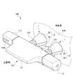
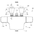
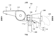
以下、本発明の吐水装置の好ましい各実施形態について、図面を参照しながら説明する。図1は、本発明の一実施形態に係る配管カバー1を配置した水栓100を示す斜視図である。図2は、水栓100の平面図であり、図3は、水栓100の側面図である。なお、以下の説明において、吐水方向とは、水が流れる方向のことであり、特に説明なく上流及び下流といった場合は水が流れる方向における上流及び下流である。また、水栓100の、壁200側を背面側、壁200に対向する側を正面側とする。
Hereinafter, preferred embodiments of the water discharge device of the present invention will be described with reference to the drawings. FIG. 1 is a perspective view showing a
水栓100は、浴室用の水栓である。図1に示すように、水栓100は、水栓本体110と、水栓本体110を壁200の内部に敷設された給湯管210及び給水管220に接続するための配管120,130と、配管120,130をそれぞれ覆う配管カバー1,1と、を有する。
水栓本体110は、正面から見てそれぞれ、中心に位置する吐水部111と、吐水部111の右側に接続される切替ハンドル112と、吐水部111の左側に接続される温度調節ハンドル113と、を備える。
The
The
吐水部111は、下面に形成される図示しない吐水口から、吸水された水を吐出する。図2及び図3に示すように、吐水部111は、背面側の水平方向における中心には水平方向に延出して下方に屈曲したシャワーエルボ111aを有する。図3に示すように、シャワーエルボ111aには、図示しないシャワー部へ湯水を給水するためのチューブ300が接続される。
切替ハンドル112は、給水先を吐水部111の吐水口かシャワー部かのいずれかに切り替えるためのものであり、水栓100の使用者は、この切替ハンドル112によって、湯水の出し止めや吐水される水量の調節を行う。
The water discharger 111 discharges the absorbed water from a water discharge port (not shown) formed on the lower surface. As shown in FIGS. 2 and 3, the
The switching handle 112 is for switching the water supply destination to either the water outlet of the
本実施形態における水栓100は、使用者が用途に応じて湯水の温度調節が可能な混合水栓であり、例えばサーモスタット混合水栓式等、適宜方式が採用される。温度調節ハンドル113は、吐水部111の内部において給湯管210及び給水管220から給水される湯水を混合する割合を調整することで、吐水される湯水の温度を調節するものである。温度調節ハンドル113は、内部に配置され且つ吐水される湯水が所定の温度(例えば、50℃)以上にならないようにするストッパー(図示しない)と、温度調節ハンドル113の外面の正面側に配置される、ストッパーを解除するためのボタン113aと、を備える。
The
配管120,130は、吐水部111の背面側に水平方向に並んで接続されて、水栓本体110を壁200に取り付けて支持する。配管120の内部は、給湯管210から給湯された湯が流通する。配管130の内部は、給水管220から給水された水が流通する。
The
続いて、図4も参照しながら、配管120及び配管カバー1について詳細に説明する。
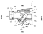
図4は、配管カバー1を配置した配管120の断面図であって、図2のA−A線断面図である。配管120及び配管130は同様の構造であるので、ここでは配管120についてのみ説明する。
配管120は、配管本体121と、ストレーナ部122と、袋ナット123と、を有する。配管120は、主に金属製の部材によって構成される。
Next, the
4 is a cross-sectional view of the
The
配管本体121は、その内部に形成された、上流側の第1流路121aと、下流側の第2流路121bと、第1流路121aと第2流路121bとの間に位置する連通流路121cと、を有する。更に、配管本体121は、連通流路121cから下側に開口し、連通流路121cを外部と連通する開口部121dを有する。開口部121dには、内側に雌ネジが形成される。また、配管本体121は、下流側の一端に形成されたフランジ部121eを有する。
第1流路121aの上流側は、給湯管210に接続される。第2流路121bの下流側は、吐水部111(水栓本体110)の背面側に、後述する袋ナット123を介して接続される。
The pipe
The upstream side of the
ストレーナ部122は、キャップ122aと、ストレーナ122bと、スピンドル122cと、を有する。
キャップ122aは、外周面に雄ネジが形成され、開口部121dに螺合して配管本体121に取り付けられる。ストレーナ122bは、連通流路121cに埋設される。ストレーナ122bは、給湯管210(給水管220)から供給される湯水から固体成分を取り除く。スピンドル122cは、キャップ122aの中心に形成された孔に嵌合されて保持され、ストレーナ部122の軸を形成する。ストレーナ122bは、キャップ122aを配管本体121から取り外す際に、キャップ122aとともに取り外すことができ、交換可能である。
キャップ122aと開口部121dとの間には、Oリング124が配置される。
The
The
An O-
袋ナット123は、フランジ部121eに係合される。袋ナット123とフランジ部121eとの間には、Oリング125が配置される。更に、袋ナット123は、水栓本体110の吐水部111の背面側に形成される図示しない取り付け部に螺合することで、配管120と水栓本体110とを接続する。
The
配管カバー1は、外観カバー部材10と、内部部材40と、を備える。
図1及び図4に示すように、外観カバー部材10は、円筒状に形成され、内部に配管120が挿通される。より詳しくは、外観カバー部材10は、背面側(壁200側)に向かって拡径した円筒状(円錐状)である。
図4に示すように、外観カバー部材10は、配管120を介して互いに対向して配置される第1の外観カバー部材20及び第2の外観カバー部材30を備える。第1の外観カバー部材20は、配管120の上側に、第2の外観カバー部材30は、配管120の下側に、それぞれ配置される。
本実施形態において外観カバー部材10(第1の外観カバー部材20及び第2の外観カバー部材30)は、ABS樹脂を成形した母材にメッキした部材であるが、特に限定はされない。
The
As shown in FIG.1 and FIG.4, the external
As shown in FIG. 4, the
In the present embodiment, the outer cover member 10 (the first
内部部材40は、外観カバー部材10(第1の外観カバー部材20)と配管120との間に配置される。内部部材40は、高分子製の部材である。内部部材40に用いられる高分子としては、特に限定されないが、樹脂やゴム等を挙げることができる。樹脂としては、ABS樹脂、AS樹脂、アクリル樹脂、ポリ塩化ビニル等が挙げられる。また、ゴムとしては、天然ゴムや、ブタジエンゴム、スチレン−ブタジエンゴムに代表される合成ゴムを挙げることができる。
The
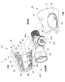
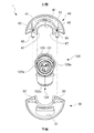
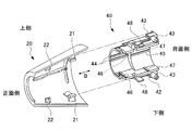
続いて、図5〜図7も参照しながら、配管カバー1についてより詳細に説明する。
図5は、配管カバー1の分解斜視図である。図6は、配管カバー1の分解背面図(壁200側から見た図)である。図5及び図6においては、配管120についても示す。また、図5では、便宜的に配管カバー1を配管120の挿通方向を軸にして回転させている。図7は、配管カバー1の第1の外観カバー部材20及び内部部材40の分解斜視図である。図7は、図5に示した回転角度における、第1の外観カバー部材20及び内部部材40の分解斜視図である。
図5〜図7に示すように、配管カバー1の外観カバー部材10及び内部部材40は図2のA−A線断面に相当する面を中心とした対称構造である。
Next, the
FIG. 5 is an exploded perspective view of the
As shown in FIGS. 5 to 7, the
図5及び図6に示すように、第1の外観カバー部材20、第2の外観カバー部材30及び内部部材40は、全て半円筒状に形成される。
また、図7に示すように、第1の外観カバー部材20は、内周に設けられた一対の係合部21,21を備える。一対の係合部21,21は、第1の外観カバー部材20の互いに対向する内面から内側に延出する。また、第1の外観カバー部材20は、内周に設けられた一対の延出部22,22を備える。一対の延出部22,22は、第1の外観カバー部材20の互いに対向する内面から内側に延出する。
As shown in FIGS. 5 and 6, the first
Moreover, as shown in FIG. 7, the 1st external
内部部材40は、中空部分41,41を形成する。中空部分41,41が形成されることで、より内面から外面への熱伝達の効率を下げることができる。内部部材40は、外周に設けられた被係合部42,42を有する。また、図5〜図7に示すように、内部部材40は、第2の外観カバー部材30側に突出した突出部43,43を有する。更に、内部部材40は、第2の外観カバー部材30側に延びて先端が鉤状に曲がった爪部48,48を有する。
The
内部部材40は、内周上面に配管120の挿通方向に延設されたリブ44,44,45を有する。リブ44,44,45は、配管本体121の上面に形成された平面に当接し、内部部材40を配管120に設置した際の、内部部材40の配管120の挿通方向への移動を容易にする。
また、内部部材40は、互いに対向する内面が平面に形成され、且つ、その内面に配管120の挿通方向に直交する方向に延設されたリブ46,46,47,47を有する。後述するように、リブ46,46,47,47の内側は、配管120の両側面に形成された平面120a,120aと接触することが可能となるように形成される。これらのリブ46,46,47,47の内側は、平面120a,120aと面接触することが可能となるように形成してもよい。
The
The
第2の外観カバー部材30は、内面と外面とを連通する孔31を有する。孔31が形成されることで、配管カバー1で配管120を覆った場合にも、キャップ122aの外面が外部に露出され(図3参照)、ストレーナ部122の取り外しが可能になる。
第2の外観カバー部材30は、互いに対向する内面に形成された一対の延出部32,32を有する。また、第2の外観カバー部材30は、互いに対向する内面に形成され、且つ、先端に上側から下側に貫通する孔の形成された一対の挿入部33,33を有する。
The 2nd
The second
続いて、配管120(配管130)への配管カバー1の取り付け方法及び配管120に配管カバー1を取り付けた状態について説明する。
配管カバー1の取り付けは、配管120,130をそれぞれ、水栓本体110及び浴室等の壁200の内部に敷設された給湯管210及び給水管220に取り付けて、水栓本体110が壁200に支持された状態で行われる。
Next, a method for attaching the
The
まず、図7に示すように、第1の外観カバー部材20と内部部材40とを、係合部21,21と被係合部42,42とが配管120の挿通方向(B方向)から突き合わされることで、内部部材40を第1の外観カバー部材20の内側に係合する。このとき、延出部22,22は、内部部材40と当接する(図5参照)。
First, as shown in FIG. 7, the first
続いて、図5及び図6に示すように、内部部材40と第1の外観カバー部材20とが一体となった部材を、上側から配管120に係合させる。この際に、リブ46,46,47,47の内側が配管120の両側面に形成された平面120a,120aに接触するようにする。
Subsequently, as shown in FIGS. 5 and 6, the member in which the
続いて、第2の外観カバー部材30を、下側から配管120に接近させて、配管120に係合された内部部材40の爪部48,48をスナップフィットにより第2の外観カバー部材30の延出部32,32に係合させる。この際に、内部部材40の突出部43,43は、第2の外観カバー部材30の挿入部33,33に形成された孔に挿入される。
このように、内部部材40と第2の外観カバー部材30を係合させることで、第1の外観カバー部材及び第2の外観カバー部材は、直接連結されず、内部部材40を介して連結されることになる。
Subsequently, the second
Thus, by engaging the
最後に、配管カバー1全体の配管120,130の挿通方向における位置を調整し、配管カバー1の背面側を壁200に接触させる(図2参照)。
Finally, the position of the
本実施形態によれば、以下の効果が奏される。
本実施形態では、配管カバー1を、外観カバー部材10と、外観カバー部材10の内側に係合され且つ配管120に係合可能である高分子製の内部部材40と、を備えるものとした。
これにより、配管120の内部を湯が流通することによって配管120が熱を持ったとしても、配管120の持つ熱が配管カバー1の外面まで伝達され難くなる。つまり、従来の配管カバーでは、本実施形態における外観カバー部材に相当する部材が直接配管に触れて位置決めされるので、配管カバーの外面が高温になってしまうおそれがあったが、本実施形態においては熱伝導率の低い高分子製の内部部材40を介して外観カバー部材10が配管120に係合及び位置決めされるので、配管カバー1の外面まで熱が伝達し難い。
本実施形態に係る配管カバー1を用いれば、水栓の使用者等が高温になった配管カバーに触れてしまうのを防ぐことができる。
According to this embodiment, the following effects are produced.
In this embodiment, the
Thereby, even if hot water flows through the inside of the
If the
また、本実施形態では、外観カバー部材10が、互いに対向して配置される第1の外観カバー部材20及び第2の外観カバー部材30を備えるものとし、これらの第1の外観カバー部材20及び第2の外観カバー部材30が内部部材40を介して連結されるものとした。
これにより、事前に配管カバー1を配管120,130に挿通させて水栓100の設置を行わずとも、水栓本体110が配管120,130によって壁200に支持された状態で配管カバー1の取り付け作業を行うことができる。
Moreover, in this embodiment, the external
Thus, the
また、本実施形態では、内部部材40が、第1の外観カバー部材20の内側に係合され、且つ、第2の外観カバー部材30側(下側)に延びて先端が鉤状に曲がった爪部48,48を有するものとした。更に、第2の外観カバー部材30が、内面に形成され且つ爪部48,48がスナップフィットにより係合される延出部32,32を有するものとした。
このように、内部部材40と外観カバー部材10とを係合するための構造において、外観カバー部材10側の構造を単純化した。これにより、外観カバー部材10を成形する際の、ヒケが発生等による歩留まりや品質の低下を防ぐことができる。
なお、メッキの施された外観カバー部材にスナップフィットによって係合するための爪部を設けると、外観カバー部材に応力がかかることでメッキ割れやメッキの剥がれが生じてしまう場合がある。本実施形態においては、内部部材40側の爪部48,48をスナップフィットによって、第2の外観カバー部材30に取り付ける構造とすることで、メッキを施した外観カバー部材10を用いた場合でも、メッキ割れやメッキの剥がれが生じてしまうのを防ぐことができる。
Further, in the present embodiment, the
Thus, in the structure for engaging the
In addition, when the nail | claw part for engaging with the external appearance cover member to which plating was given by snap fitting is provided, a plating crack and peeling of a plating may arise because stress is applied to an external appearance cover member. In the present embodiment, the
また、本実施形態では、第1の外観カバー部材20の内周に設けられた係合部21,21と、内部部材40の外周に設けられた被係合部42,42とが、配管120の挿通方向から突き合わされることで内部部材40が第1の外観カバー部材20の内側に係合されるものとした。
これにより、配管カバー1の組み立てが(施工)が容易になる。つまり、本実施形態によれば、内部部材40と第1の外観カバー部材20とを事前にアセンブリ化しておき、これらが一体となった部材を用いて現場での施工を行うことができるので、現場での作業負担が軽減される。
In the present embodiment, the
Thereby, assembly (construction) of the
また、本実施形態では、半円筒状に形成された配管カバー1の互いに対向する内面に、配管120,130の挿通方向に直交する方向にリブ46,46,47,47を延設した。更に、この配管カバー1を、リブ46,46,47,47が配管120,130の両側面に形成された平面と接触するように取り付けた。
これにより、配管120,130の延びる方向を軸とした配管カバー1の角度を変えて、配管カバー1を配管120,130に取り付けることが難しくなる。すなわち、配管カバー1の取り付けの際の、配管120,130の延びる方向を軸とした回転方向の位置決めが容易になる。
また、配管カバー1と配管120,130とが、面同士でなく、リブと平面とが接触するように配管カバー1が取り付けられることで、配管カバー1の配管120,130の延びる方向における位置調整も容易になる。
In the present embodiment, the
This makes it difficult to attach the
In addition, the
また、本実施形態では、水栓100が、水栓本体110と、水栓本体110を壁200の内部に敷設された給湯管210(給水管220)に接続するための配管120(配管130)と、配管カバー1と、を有するものとした。
これにより、配管の持つ熱が配管カバーの外面まで伝達され難く、意匠性の高い水栓を提供できる。
In the present embodiment, the
Thereby, the heat which a piping has is hard to be transmitted to the outer surface of a piping cover, and a faucet with high design nature can be provided.
なお、本発明は上記実施形態に限定されるものではなく、本発明の目的を達成できる範囲での変形、改良等は本発明に含まれる。
本実施形態においては、配管カバー1を浴室用の水栓に適用したが、これに限定されず、例えば、キッチン用の水栓に適用することもできる。
また、本実施形態においては、外観カバー部材10は、2つの部材(第1の外観カバー部材20及び第2の外観カバー部材30)から構成したが、これに限定されない。例えば、外観カバー部材は、1つの筒状部材から構成してもよいし、3以上の部材から構成してもよい。
It should be noted that the present invention is not limited to the above-described embodiment, and modifications, improvements, etc. within a scope that can achieve the object of the present invention are included in the present invention.
In the present embodiment, the
Moreover, in this embodiment, although the external
1…配管カバー
10…外観カバー部材
20…第1の外観カバー部材
21,21…係合部
30…第2の外観カバー部材
32,32…延出部
40…内部部材
42,42…被係合部
46,46,47,47…リブ
48,48…爪部
100…水栓
110…水栓本体
120,130…配管
210…給湯管
220…給水管
DESCRIPTION OF
Claims (5)
内部に前記配管が挿通される外観カバー部材と、
前記外観カバー部材の内側に係合され且つ前記配管に係合可能である高分子製の内部部材と、を備え、
前記外観カバー部材は、互いに対向して配置される第1の外観カバー部材及び第2の外観カバー部材を備え、
前記第1の外観カバー部材及び前記第2の外観カバー部材は、前記内部部材を介して連結され、
前記内部部材は、前記第1の外観カバー部材の内側に係合され、且つ、前記第2の外観カバー部材側に延びて先端が鉤状に曲がった爪部を有し、
前記第2の外観カバー部材は、内面に形成され且つ前記爪部がスナップフィットにより係合される延出部を有する配管カバー。 A pipe cover for covering the pipe,
An exterior cover member into which the pipe is inserted;
An inner member made of a polymer that is engaged inside the outer appearance cover member and engageable with the pipe;
The exterior cover member includes a first exterior cover member and a second exterior cover member that are disposed to face each other.
The first appearance cover member and the second appearance cover member are connected via the internal member ,
The internal member has a claw portion that is engaged with the inside of the first appearance cover member and that extends toward the second appearance cover member and has a tip bent in a hook shape.
The second appearance cover member, the pipe cover that having a extending portion and the claw portion is formed on the inner surface is engaged by a snap fit.
内部に前記配管が挿通される外観カバー部材と、An exterior cover member into which the pipe is inserted;
前記外観カバー部材の内側に係合され且つ前記配管に係合可能である高分子製の内部部材と、を備え、An inner member made of a polymer that is engaged inside the outer appearance cover member and engageable with the pipe;
前記外観カバー部材は、互いに対向して配置される第1の外観カバー部材及び第2の外観カバー部材を備え、The exterior cover member includes a first exterior cover member and a second exterior cover member that are disposed to face each other.
前記第1の外観カバー部材及び前記第2の外観カバー部材は、前記内部部材を介して連結され、The first appearance cover member and the second appearance cover member are connected via the internal member,
内部部材と第2の外観カバーを係合させることで、第1の外観カバー部材及び第2の外観カバー部材は直接連結されず、内部部材を介して連結される配管カバー。A piping cover that is connected via an internal member without first directly connecting the first external cover member and the second external cover member by engaging the internal member with the second external cover.
配管を覆うための前記配管カバーは、
内部に前記配管が挿通される外観カバー部材と、
前記外観カバー部材の内側に係合され且つ前記配管に係合可能である高分子製の内部部材と、を備え、
前記外観カバー部材は、互いに対向して配置される第1の外観カバー部材及び第2の外観カバー部材を備え、
前記第1の外観カバー部材及び前記第2の外観カバー部材は、前記内部部材を介して連結され、
前記内部部材は、半円筒状に形成され、且つ、互いに対向する内面に前記配管の挿通方向に直交する方向に延設されたリブを有し、
前記リブの内側は、前記配管の両側面に形成された平面と接触することが可能である前記配管カバーを、
前記配管に、前記リブの内側が前記平面に接触するように取り付ける配管カバーの取り付け方法。 A method for attaching a piping cover,
The piping cover for covering the piping is
An exterior cover member into which the pipe is inserted;
An inner member made of a polymer that is engaged inside the outer appearance cover member and engageable with the pipe;
The exterior cover member includes a first exterior cover member and a second exterior cover member that are disposed to face each other.
The first appearance cover member and the second appearance cover member are connected via the internal member,
The inner member is formed in a semi-cylindrical shape, and has ribs extending on the inner surfaces facing each other in a direction perpendicular to the insertion direction of the pipe,
Inside the ribs, a can be in contact with both side surfaces formed on the plane of the pipe the pipe cover,
A method for attaching a piping cover to the piping so that the inside of the rib contacts the flat surface.
前記水栓本体を給湯管又は給水管に接続するための配管と、
前記配管を覆う請求項1から3のいずれか記載の配管カバーと、を有する水栓。 The faucet body,
Piping for connecting the faucet body to a hot water supply pipe or a water supply pipe;
A water faucet having a piping cover according to any one of claims 1 to 3, which covers the piping.
Priority Applications (1)
| Application Number | Priority Date | Filing Date | Title |
|---|---|---|---|
| JP2014047398A JP6381237B2 (en) | 2014-03-11 | 2014-03-11 | Piping cover, mounting method and faucet |
Applications Claiming Priority (1)
| Application Number | Priority Date | Filing Date | Title |
|---|---|---|---|
| JP2014047398A JP6381237B2 (en) | 2014-03-11 | 2014-03-11 | Piping cover, mounting method and faucet |
Publications (2)
| Publication Number | Publication Date |
|---|---|
| JP2015169063A JP2015169063A (en) | 2015-09-28 |
| JP6381237B2 true JP6381237B2 (en) | 2018-08-29 |
Family
ID=54202054
Family Applications (1)
| Application Number | Title | Priority Date | Filing Date |
|---|---|---|---|
| JP2014047398A Active JP6381237B2 (en) | 2014-03-11 | 2014-03-11 | Piping cover, mounting method and faucet |
Country Status (1)
| Country | Link |
|---|---|
| JP (1) | JP6381237B2 (en) |
Families Citing this family (2)
| Publication number | Priority date | Publication date | Assignee | Title |
|---|---|---|---|---|
| WO2016129617A1 (en) * | 2015-02-10 | 2016-08-18 | テクノポリマー株式会社 | Article comprising plated component |
| JP6886901B2 (en) * | 2017-08-31 | 2021-06-16 | 株式会社Lixil | Faucet device |
Family Cites Families (3)
| Publication number | Priority date | Publication date | Assignee | Title |
|---|---|---|---|---|
| JP2005290663A (en) * | 2004-03-31 | 2005-10-20 | Kvk Corp | Cover mounting structure |
| JP4895933B2 (en) * | 2007-06-29 | 2012-03-14 | 株式会社Lixil | Wall-mounted faucet |
| JP5982658B2 (en) * | 2012-02-29 | 2016-08-31 | 株式会社Lixil | Faucet with cover |
-
2014
- 2014-03-11 JP JP2014047398A patent/JP6381237B2/en active Active
Also Published As
| Publication number | Publication date |
|---|---|
| JP2015169063A (en) | 2015-09-28 |
Similar Documents
| Publication | Publication Date | Title |
|---|---|---|
| US9758949B2 (en) | Fluid delivery system with a housing and at least one fluid inlet and one fluid outlet | |
| US20180209129A1 (en) | Mounting structure for bidet | |
| KR101721067B1 (en) | A faucet | |
| US9157221B2 (en) | All-in-one bath mixer pop-up waste and overflow assembly | |
| KR102062336B1 (en) | hydrant for warm and cold water | |
| JP6381237B2 (en) | Piping cover, mounting method and faucet | |
| TWI545244B (en) | Sanitary fitting | |
| US9803350B2 (en) | Flush lever and assembly | |
| JP5695264B1 (en) | Water-saving device for shower facilities | |
| JP2006193923A (en) | Detaching and attaching structure of strainer member | |
| JP6529897B2 (en) | Water discharge head attached to faucet and faucet | |
| JP6366965B2 (en) | Mounting structure and water discharge device provided with mounting structure | |
| JP7114023B2 (en) | faucet device | |
| KR101937484B1 (en) | Water supply valve | |
| JP6543894B2 (en) | Faucet device | |
| JP2006193924A (en) | Lever-handle fixing structure of faucet | |
| JP5138973B2 (en) | shower head | |
| JP2020023822A (en) | Faucet device | |
| JP6137728B2 (en) | Faucet mounting structure | |
| KR200454292Y1 (en) | Faucet valve | |
| JP4381546B2 (en) | Hose fittings | |
| JP2005282102A (en) | Shower pipe support structure | |
| CA2802806C (en) | Fluid delivery system with a housing and at least one fluid inlet and one fluid outlet | |
| JP7263059B2 (en) | Water discharge device | |
| US20110248098A1 (en) | Portable faucet sprayer |
Legal Events
| Date | Code | Title | Description |
|---|---|---|---|
| A621 | Written request for application examination |
Free format text: JAPANESE INTERMEDIATE CODE: A621 Effective date: 20160721 |
|
| A977 | Report on retrieval |
Free format text: JAPANESE INTERMEDIATE CODE: A971007 Effective date: 20170522 |
|
| A131 | Notification of reasons for refusal |
Free format text: JAPANESE INTERMEDIATE CODE: A131 Effective date: 20170606 |
|
| A521 | Written amendment |
Free format text: JAPANESE INTERMEDIATE CODE: A523 Effective date: 20170727 |
|
| A131 | Notification of reasons for refusal |
Free format text: JAPANESE INTERMEDIATE CODE: A131 Effective date: 20180109 |
|
| A521 | Written amendment |
Free format text: JAPANESE INTERMEDIATE CODE: A523 Effective date: 20180302 |
|
| TRDD | Decision of grant or rejection written | ||
| A01 | Written decision to grant a patent or to grant a registration (utility model) |
Free format text: JAPANESE INTERMEDIATE CODE: A01 Effective date: 20180731 |
|
| A61 | First payment of annual fees (during grant procedure) |
Free format text: JAPANESE INTERMEDIATE CODE: A61 Effective date: 20180731 |
|
| R150 | Certificate of patent or registration of utility model |
Ref document number: 6381237 Country of ref document: JP Free format text: JAPANESE INTERMEDIATE CODE: R150 |
|
| S111 | Request for change of ownership or part of ownership |
Free format text: JAPANESE INTERMEDIATE CODE: R313111 |
|
| R350 | Written notification of registration of transfer |
Free format text: JAPANESE INTERMEDIATE CODE: R350 |