JP6376662B2 - Power transmission system for vehicles - Google Patents
Power transmission system for vehicles Download PDFInfo
- Publication number
- JP6376662B2 JP6376662B2 JP2015097106A JP2015097106A JP6376662B2 JP 6376662 B2 JP6376662 B2 JP 6376662B2 JP 2015097106 A JP2015097106 A JP 2015097106A JP 2015097106 A JP2015097106 A JP 2015097106A JP 6376662 B2 JP6376662 B2 JP 6376662B2
- Authority
- JP
- Japan
- Prior art keywords
- clutch
- force
- pressure plate
- assist
- assist force
- Prior art date
- Legal status (The legal status is an assumption and is not a legal conclusion. Google has not performed a legal analysis and makes no representation as to the accuracy of the status listed.)
- Active
Links
- 230000005540 biological transmission Effects 0.000 title claims description 107
- 238000003825 pressing Methods 0.000 claims description 18
- 238000007562 laser obscuration time method Methods 0.000 claims description 2
- 238000006073 displacement reaction Methods 0.000 description 23
- 230000007246 mechanism Effects 0.000 description 14
- 230000001276 controlling effect Effects 0.000 description 8
- 238000000034 method Methods 0.000 description 8
- 230000008569 process Effects 0.000 description 8
- 239000000446 fuel Substances 0.000 description 6
- 239000000463 material Substances 0.000 description 5
- 230000002093 peripheral effect Effects 0.000 description 5
- 230000008859 change Effects 0.000 description 3
- 238000002485 combustion reaction Methods 0.000 description 3
- 239000000203 mixture Substances 0.000 description 3
- 229910000639 Spring steel Inorganic materials 0.000 description 2
- 239000010960 cold rolled steel Substances 0.000 description 2
- 230000007423 decrease Effects 0.000 description 2
- 238000001514 detection method Methods 0.000 description 2
- 238000010586 diagram Methods 0.000 description 2
- 239000002828 fuel tank Substances 0.000 description 2
- 229910052751 metal Inorganic materials 0.000 description 2
- 239000002184 metal Substances 0.000 description 2
- 238000004080 punching Methods 0.000 description 2
- 230000004044 response Effects 0.000 description 2
- 238000003860 storage Methods 0.000 description 2
- 230000003313 weakening effect Effects 0.000 description 2
- 229910000838 Al alloy Inorganic materials 0.000 description 1
- 238000010521 absorption reaction Methods 0.000 description 1
- 230000009471 action Effects 0.000 description 1
- 229910052782 aluminium Inorganic materials 0.000 description 1
- XAGFODPZIPBFFR-UHFFFAOYSA-N aluminium Chemical compound [Al] XAGFODPZIPBFFR-UHFFFAOYSA-N 0.000 description 1
- 230000000052 comparative effect Effects 0.000 description 1
- 239000002783 friction material Substances 0.000 description 1
- 230000013011 mating Effects 0.000 description 1
- 239000003595 mist Substances 0.000 description 1
- 230000004048 modification Effects 0.000 description 1
- 238000012986 modification Methods 0.000 description 1
- 230000007935 neutral effect Effects 0.000 description 1
- 230000001105 regulatory effect Effects 0.000 description 1
- 238000005728 strengthening Methods 0.000 description 1
- 230000007704 transition Effects 0.000 description 1
Images


Classifications
-
- F—MECHANICAL ENGINEERING; LIGHTING; HEATING; WEAPONS; BLASTING
- F16—ENGINEERING ELEMENTS AND UNITS; GENERAL MEASURES FOR PRODUCING AND MAINTAINING EFFECTIVE FUNCTIONING OF MACHINES OR INSTALLATIONS; THERMAL INSULATION IN GENERAL
- F16D—COUPLINGS FOR TRANSMITTING ROTATION; CLUTCHES; BRAKES
- F16D13/00—Friction clutches
- F16D13/04—Friction clutches with means for actuating or keeping engaged by a force derived at least partially from one of the shafts to be connected
-
- F—MECHANICAL ENGINEERING; LIGHTING; HEATING; WEAPONS; BLASTING
- F16—ENGINEERING ELEMENTS AND UNITS; GENERAL MEASURES FOR PRODUCING AND MAINTAINING EFFECTIVE FUNCTIONING OF MACHINES OR INSTALLATIONS; THERMAL INSULATION IN GENERAL
- F16D—COUPLINGS FOR TRANSMITTING ROTATION; CLUTCHES; BRAKES
- F16D13/00—Friction clutches
- F16D13/22—Friction clutches with axially-movable clutching members
- F16D13/38—Friction clutches with axially-movable clutching members with flat clutching surfaces, e.g. discs
- F16D13/52—Clutches with multiple lamellae ; Clutches in which three or more axially moveable members are fixed alternately to the shafts to be coupled and are pressed from one side towards an axially-located member
-
- F—MECHANICAL ENGINEERING; LIGHTING; HEATING; WEAPONS; BLASTING
- F16—ENGINEERING ELEMENTS AND UNITS; GENERAL MEASURES FOR PRODUCING AND MAINTAINING EFFECTIVE FUNCTIONING OF MACHINES OR INSTALLATIONS; THERMAL INSULATION IN GENERAL
- F16D—COUPLINGS FOR TRANSMITTING ROTATION; CLUTCHES; BRAKES
- F16D48/00—External control of clutches
- F16D48/06—Control by electric or electronic means, e.g. of fluid pressure
-
- F—MECHANICAL ENGINEERING; LIGHTING; HEATING; WEAPONS; BLASTING
- F16—ENGINEERING ELEMENTS AND UNITS; GENERAL MEASURES FOR PRODUCING AND MAINTAINING EFFECTIVE FUNCTIONING OF MACHINES OR INSTALLATIONS; THERMAL INSULATION IN GENERAL
- F16H—GEARING
- F16H3/00—Toothed gearings for conveying rotary motion with variable gear ratio or for reversing rotary motion
- F16H3/02—Toothed gearings for conveying rotary motion with variable gear ratio or for reversing rotary motion without gears having orbital motion
- F16H3/08—Toothed gearings for conveying rotary motion with variable gear ratio or for reversing rotary motion without gears having orbital motion exclusively or essentially with continuously meshing gears, that can be disengaged from their shafts
- F16H3/087—Toothed gearings for conveying rotary motion with variable gear ratio or for reversing rotary motion without gears having orbital motion exclusively or essentially with continuously meshing gears, that can be disengaged from their shafts characterised by the disposition of the gears
- F16H3/091—Toothed gearings for conveying rotary motion with variable gear ratio or for reversing rotary motion without gears having orbital motion exclusively or essentially with continuously meshing gears, that can be disengaged from their shafts characterised by the disposition of the gears including a single countershaft
-
- F—MECHANICAL ENGINEERING; LIGHTING; HEATING; WEAPONS; BLASTING
- F16—ENGINEERING ELEMENTS AND UNITS; GENERAL MEASURES FOR PRODUCING AND MAINTAINING EFFECTIVE FUNCTIONING OF MACHINES OR INSTALLATIONS; THERMAL INSULATION IN GENERAL
- F16H—GEARING
- F16H61/00—Control functions within control units of change-speed- or reversing-gearings for conveying rotary motion ; Control of exclusively fluid gearing, friction gearing, gearings with endless flexible members or other particular types of gearing
- F16H61/02—Control functions within control units of change-speed- or reversing-gearings for conveying rotary motion ; Control of exclusively fluid gearing, friction gearing, gearings with endless flexible members or other particular types of gearing characterised by the signals used
- F16H61/0202—Control functions within control units of change-speed- or reversing-gearings for conveying rotary motion ; Control of exclusively fluid gearing, friction gearing, gearings with endless flexible members or other particular types of gearing characterised by the signals used the signals being electric
- F16H61/0204—Control functions within control units of change-speed- or reversing-gearings for conveying rotary motion ; Control of exclusively fluid gearing, friction gearing, gearings with endless flexible members or other particular types of gearing characterised by the signals used the signals being electric for gearshift control, e.g. control functions for performing shifting or generation of shift signal
-
- F—MECHANICAL ENGINEERING; LIGHTING; HEATING; WEAPONS; BLASTING
- F16—ENGINEERING ELEMENTS AND UNITS; GENERAL MEASURES FOR PRODUCING AND MAINTAINING EFFECTIVE FUNCTIONING OF MACHINES OR INSTALLATIONS; THERMAL INSULATION IN GENERAL
- F16H—GEARING
- F16H63/00—Control outputs from the control unit to change-speed- or reversing-gearings for conveying rotary motion or to other devices than the final output mechanism
- F16H63/02—Final output mechanisms therefor; Actuating means for the final output mechanisms
- F16H63/30—Constructional features of the final output mechanisms
-
- F—MECHANICAL ENGINEERING; LIGHTING; HEATING; WEAPONS; BLASTING
- F16—ENGINEERING ELEMENTS AND UNITS; GENERAL MEASURES FOR PRODUCING AND MAINTAINING EFFECTIVE FUNCTIONING OF MACHINES OR INSTALLATIONS; THERMAL INSULATION IN GENERAL
- F16D—COUPLINGS FOR TRANSMITTING ROTATION; CLUTCHES; BRAKES
- F16D2500/00—External control of clutches by electric or electronic means
- F16D2500/10—System to be controlled
- F16D2500/102—Actuator
- F16D2500/1026—Hydraulic
-
- F—MECHANICAL ENGINEERING; LIGHTING; HEATING; WEAPONS; BLASTING
- F16—ENGINEERING ELEMENTS AND UNITS; GENERAL MEASURES FOR PRODUCING AND MAINTAINING EFFECTIVE FUNCTIONING OF MACHINES OR INSTALLATIONS; THERMAL INSULATION IN GENERAL
- F16D—COUPLINGS FOR TRANSMITTING ROTATION; CLUTCHES; BRAKES
- F16D2500/00—External control of clutches by electric or electronic means
- F16D2500/30—Signal inputs
- F16D2500/302—Signal inputs from the actuator
- F16D2500/3023—Force
-
- F—MECHANICAL ENGINEERING; LIGHTING; HEATING; WEAPONS; BLASTING
- F16—ENGINEERING ELEMENTS AND UNITS; GENERAL MEASURES FOR PRODUCING AND MAINTAINING EFFECTIVE FUNCTIONING OF MACHINES OR INSTALLATIONS; THERMAL INSULATION IN GENERAL
- F16D—COUPLINGS FOR TRANSMITTING ROTATION; CLUTCHES; BRAKES
- F16D2500/00—External control of clutches by electric or electronic means
- F16D2500/50—Problem to be solved by the control system
- F16D2500/502—Relating the clutch
- F16D2500/50239—Soft clutch engagement
-
- F—MECHANICAL ENGINEERING; LIGHTING; HEATING; WEAPONS; BLASTING
- F16—ENGINEERING ELEMENTS AND UNITS; GENERAL MEASURES FOR PRODUCING AND MAINTAINING EFFECTIVE FUNCTIONING OF MACHINES OR INSTALLATIONS; THERMAL INSULATION IN GENERAL
- F16H—GEARING
- F16H63/00—Control outputs from the control unit to change-speed- or reversing-gearings for conveying rotary motion or to other devices than the final output mechanism
- F16H63/02—Final output mechanisms therefor; Actuating means for the final output mechanisms
- F16H63/30—Constructional features of the final output mechanisms
- F16H2063/3093—Final output elements, i.e. the final elements to establish gear ratio, e.g. dog clutches or other means establishing coupling to shaft
Description
本発明は、自動二輪車や四輪バギー車などの自走式車両に搭載される車両用動力伝達システムに関する。 The present invention relates to a vehicle power transmission system mounted on a self-propelled vehicle such as a motorcycle or a four-wheel buggy.
従来から、自動二輪車や四輪バギー車などの自走式車両においては、エンジン(原動機)で発生した駆動力を駆動輪に伝達するために動力伝達装置が設けられている。動力伝達装置は、エンジンのクランクシャフトに対して接続および遮断しながらこのクランクシャフトの回転数を変速しつつ駆動輪に伝達する機械装置であり、主としてクラッチとトランスミッションによって構成されている。 2. Description of the Related Art Conventionally, in a self-propelled vehicle such as a motorcycle or a four-wheel buggy, a power transmission device is provided to transmit driving force generated by an engine (prime mover) to driving wheels. The power transmission device is a mechanical device that transmits and transmits the rotational speed of the crankshaft to the drive wheel while shifting and connecting to and disconnecting from the crankshaft of the engine, and mainly includes a clutch and a transmission.
ここで、クラッチとは、エンジンのクランクシャフトに対して接続および遮断しながら同クランクシャフトの回転駆動力をトランスミッション側に伝達する機械装置である。また、トランスミッションとは、エンジンのクランクシャフトの回転数を複数のギアの組合せによって構成される複数の変速段で変速させて駆動輪側に伝達する機械装置である。 Here, the clutch is a mechanical device that transmits the rotational driving force of the crankshaft to the transmission side while being connected to and disconnected from the crankshaft of the engine. The transmission is a mechanical device that changes the number of rotations of the crankshaft of the engine at a plurality of shift speeds constituted by a combination of a plurality of gears and transmits it to the drive wheel side.
この場合、クラッチには、例えば、下記特許文献1に示すように、被動側クラッチ板(クラッチプレート)を保持するクラッチ部材(クラッチハブ)およびこのクラッチ部材に対向配置されて駆動側クラッチ板(フリクションプレート)を押圧するプレッシャ部材(プレッシャプレート)の各対向面に圧接アシスト用カムが設けられたものがある。 In this case, the clutch includes a clutch member (clutch hub) that holds a driven-side clutch plate (clutch plate) and a drive-side clutch plate (friction) that is disposed opposite to the clutch member, as shown in Patent Document 1, for example. Some pressure assist members (pressure plates) that press the plate) are provided with pressure-contact assist cams.
この圧接アシスト用カムは、クラッチにおけるエンジンの駆動力の伝達状態への移行時にクラッチ部材とプレッシャ部材との間で相対回転が生じたとき、駆動側クラッチ板と従動側クラッチ板との圧接力を増加させるアシスト力を生じさせるための傾斜面からなるクラッチ部材側第1カム面(ハブ側カム部)とプレッシャ側第1カム面(プレッシャ側カム部)とで構成されたアシスト機構である。これにより、上記特許文献1に記載された動力伝達装置においては、アシスト機構によるアシスト力によって駆動側クラッチ板と従動側クラッチ板とが早期に圧接して駆動力の伝達状態に移行するとともにエンジン等からの振動がクラッチレバーに伝達されることを防止することができる。 The cam for assisting the pressure contact is configured to generate a pressure contact force between the drive side clutch plate and the driven side clutch plate when a relative rotation occurs between the clutch member and the pressure member at the time of transition to the transmission state of the driving force of the engine in the clutch. This is an assist mechanism composed of a clutch member side first cam surface (hub side cam portion) and a pressure side first cam surface (pressure side cam portion), which are inclined surfaces for generating an increasing assist force. Thereby, in the power transmission device described in Patent Document 1, the driving clutch plate and the driven clutch plate are brought into early contact with each other by the assist force of the assist mechanism to shift to the driving force transmission state and the engine or the like. Can be prevented from being transmitted to the clutch lever.
しかしながら、上記特許文献1に記載された動力伝達装置においては、車両の運転者がクラッチレバーを手動操作した場合にアシスト機構によってクラッチが運転者の意図よりも早く駆動力の伝達状態となって違和感を覚えることがあるという問題があった。 However, in the power transmission device described in Patent Literature 1, when the driver of the vehicle manually operates the clutch lever, the assist mechanism causes the clutch to be in a state where the driving force is transmitted earlier than the driver's intention. There was a problem that you might remember.
本発明は上記問題に対処するためなされたもので、その目的は、アシスト機構を備えたクラッチにおいて円滑に駆動力の伝達状態に移行することにより車両の運転者が違和感なく運転することができる車両用動力伝達システムを提供することにある。 The present invention has been made in order to address the above-described problem, and an object of the present invention is to provide a vehicle that allows a driver of the vehicle to drive without a sense of incongruity by smoothly shifting to a transmission state of driving force in a clutch having an assist mechanism. It is to provide a power transmission system.
上記目的を達成するため、本発明の特徴は、車両に搭載されるエンジンの駆動力を回転速度を変速させつつ車両の駆動輪に伝達するトランスミッションと、エンジンから伝達される駆動力によって回転駆動するフリクションプレートに対向配置されるクラッチプレートを保持して駆動力をトランスミッションに伝達するクラッチハブ、および同クラッチハブに対して接近または離隔可能かつ相対回転可能な状態で隣接配置されてフリクションプレートまたはクラッチプレートを押圧弾性体によって弾性的に押圧するプレッシャプレートを備えてエンジンから伝達される駆動力をトランスミッションに伝達または遮断するクラッチとを備え、クラッチは、エンジンの駆動力の伝達状態への移行時にクラッチハブとプレッシャプレートとの間で相対回転が生じたとき、フリクションプレートとクラッチプレートとの圧接力を増加させるアシスト力を生じさせるための傾斜面からなるハブ側アシストカム部およびプレッシャ側アシストカム部をクラッチハブおよびプレッシャプレートにそれぞれ有した車両用動力伝達システムにおいて、クラッチを駆動力の遮断状態とするために押圧弾性体の弾性力に抗してプレッシャプレートをフリクションプレートまたはクラッチプレートから離隔させるクラッチOFF押圧力をプレッシャプレートに付与するクラッチアクチュエータと、クラッチアクチュエータの作動を制御してクラッチにおける駆動力の伝達および遮断を制御する制御装置とを備え、制御装置は、クラッチを駆動力の伝達状態に移行させる際に、クラッチアクチュエータの作動を制御してプレッシャプレートに付与するクラッチOFF押圧力を押圧弾性体の弾性力よりも弱めつつプレッシャプレートにアシスト力未満の力で同アシスト力に抗する抗アシスト力を付与することによりアシスト力の増加を抑えることにある。 In order to achieve the above object, a feature of the present invention is that a driving force of an engine mounted on a vehicle is transmitted to driving wheels of the vehicle while changing a rotational speed, and is rotationally driven by a driving force transmitted from the engine. A clutch hub that holds the clutch plate disposed opposite to the friction plate and transmits the driving force to the transmission, and is disposed adjacent to the clutch hub in a state in which the clutch hub can be approached, separated from, or relatively rotated. A pressure plate that elastically presses the drive force transmitted from the engine, and a clutch that transmits or interrupts the driving force transmitted from the engine to the transmission. Between the pressure plate and the pressure plate When the rotation occurs, the clutch hub and the pressure plate each have a hub side assist cam portion and a pressure side assist cam portion that are inclined surfaces for generating an assist force that increases the pressure contact force between the friction plate and the clutch plate. In a vehicle power transmission system, a clutch that applies a clutch OFF pressing force to the pressure plate to separate the pressure plate from the friction plate or the clutch plate against the elastic force of the pressing elastic body in order to put the clutch in a state where the driving force is cut off. An actuator and a control device that controls the transmission and disconnection of the driving force in the clutch by controlling the operation of the clutch actuator, and the control device controls the operation of the clutch actuator when the clutch is shifted to the transmission state of the driving force. The assist force is increased by applying an anti-assist force against the assist force to the pressure plate with a force less than the assist force while making the clutch OFF pressing force applied to the pressure plate weaker than the elastic force of the pressing elastic body. It is to suppress.
このように構成した本発明の特徴によれば、車両用動力伝達システムは、クラッチを駆動力の伝達状態であるクラッチON状態と駆動力の遮断状態であるクラッチOFF状態とするクラッチアクチュエータおよびこのクラッチアクチュエータの作動を制御する制御装置を備えるとともに、この制御装置がクラッチアクチュエータの作動を制御してプレッシャプレートに付与するクラッチOFF押圧力を押圧弾性体の弾性力よりも弱めつつアシスト力未満の力でアシスト力に抗する抗アシスト力を付与してアシスト力の増加を抑えている。これにより、車両用動力伝達システムは、クラッチが従来技術に比べてゆっくり円滑にクラッチON状態に移行するため、運転者は違和感なく車両の運転をすることができる。 According to the characteristics of the present invention configured as described above, the vehicle power transmission system includes a clutch actuator that causes the clutch to be in a clutch ON state that is a driving force transmission state and a clutch OFF state that is a driving force cutoff state, and the clutch. A control device for controlling the operation of the actuator is provided, and this control device controls the operation of the clutch actuator to weaken the clutch OFF pressing force applied to the pressure plate with a force less than the assist force while weakening the elastic force of the pressing elastic body. Anti-assist force against the assist force is applied to suppress the increase of assist force. As a result, in the vehicle power transmission system, the clutch shifts to the clutch ON state more smoothly and smoothly than in the prior art, so that the driver can drive the vehicle without feeling uncomfortable.
また、本発明の他の特徴は、前記車両用動力伝達システムにおいて、制御装置は、クラッチアクチュエータの作動を制御してクラッチが半クラッチ状態に入る以前にプレッシャプレートに抗アシスト力を付与することにある。この場合、半クラッチ状態とは、クラッチにおけるフリクションプレートとクラッチプレートが完全に密着する前の状態においてエンジンの回転駆動力の一部が駆動輪側に伝達される不完全な伝達状態である。 Another feature of the present invention is that in the power transmission system for a vehicle, the control device applies an anti-assist force to the pressure plate before the clutch enters a half-clutch state by controlling the operation of the clutch actuator. is there. In this case, the half-clutch state is an incomplete transmission state in which a part of the rotational driving force of the engine is transmitted to the drive wheels before the friction plate and the clutch plate in the clutch are completely in close contact with each other.
このように構成した本発明の他の特徴によれば、車両用動力伝達システムは、制御装置がクラッチアクチュエータの作動を制御してクラッチが半クラッチ状態に入るよりも前にプレッシャプレートに抗アシスト力を付与してアシスト力の増加を抑える。これにより、車両用動力伝達システムは、クラッチアクチュエータがアシスト力に抗する抗アシスト力を事前に発生させるため、アシスト力の発生当初からアシスト力の増加を抑えてクラッチをゆっくりと円滑にクラッチON状態に移行させることができ、運転者は違和感なく車両の運転をすることができる。 According to another aspect of the invention configured as described above, the power transmission system for a vehicle has an anti-assist force applied to the pressure plate before the control device controls the operation of the clutch actuator and the clutch enters the half-clutch state. To suppress the increase in assist power. As a result, the vehicle power transmission system generates an anti-assist force that the clutch actuator resists the assist force in advance, so that the clutch is slowly and smoothly turned on while suppressing the increase of the assist force from the beginning. The driver can drive the vehicle without a sense of incongruity.
また、本発明の他の特徴は、前記車両用動力伝達システムにおいて、制御装置は、クラッチアクチュエータの作動を制御してアシスト力が発生した後でかつアシスト力が最大値となる前にプレッシャプレートに対してアシスト力に向かう向きの抗アシスト力を付与することにある。 Another feature of the present invention is that in the power transmission system for a vehicle, the control device controls the operation of the clutch actuator to generate an assist force, and before the assist force reaches the maximum value, In contrast, an anti-assist force in a direction toward the assist force is applied.
このように構成した本発明の他の特徴によれば、車両用動力伝達システムは、制御装置がクラッチアクチュエータの作動を制御してアシスト力が発生した後でかつアシスト力が最大値となる前にプレッシャプレートに対してアシスト力に向かう向きの抗アシスト力を付与するため、大きなアシスト力の増加をより確実に抑えてクラッチをゆっくりとクラッチON状態に移行させることができ、運転者は違和感なく車両の運転をすることができる。 According to another aspect of the invention configured as described above, the vehicular power transmission system is provided after the control device controls the operation of the clutch actuator to generate the assist force and before the assist force reaches the maximum value. Since the anti-assist force in the direction toward the assist force is applied to the pressure plate, the increase of the large assist force can be more reliably suppressed, and the clutch can be slowly shifted to the clutch ON state, so that the driver can feel comfortable. Can drive.
また、本発明の他の特徴は、前記車両用動力伝達システムにおいて、制御装置は、クラッチアクチュエータの作動を制御してアシスト力が発生した後最大値に達するまでの間の中間時にプレッシャプレートに抗アシスト力を付与することにある。 According to another aspect of the present invention, in the power transmission system for a vehicle, the control device controls the operation of the clutch actuator and resists the pressure plate at an intermediate time between the generation of the assist force and the maximum value. It is to give assist power.
このように構成した本発明の他の特徴によれば、車両用動力伝達システムは、制御装置がクラッチアクチュエータの作動を制御してアシスト力が発生した後最大値に達するまでのアシスト力の作用時間の中間時にプレッシャプレートに抗アシスト力を付与するため、アシスト力が発生した直後のアシスト力の作用時間の前半においてはクラッチOFF側に変位する大きな抗アシスト力が生じないため、円滑にクラッチON状態に移行させることができ、運転者は違和感なく車両の運転をすることができる。 According to another aspect of the invention configured as described above, the vehicular power transmission system is configured such that the control device controls the operation of the clutch actuator to generate the assist force, and then the assist force is applied until reaching the maximum value. Since the anti-assist force is applied to the pressure plate during the intermediate period of time, since the large anti-assist force that displaces to the clutch OFF side does not occur in the first half of the operation time of the assist force immediately after the assist force is generated, the clutch is turned on smoothly. The driver can drive the vehicle without a sense of incongruity.
また、本発明の他の特徴は、前記車両用動力伝達システムにおいて、制御装置は、クラッチアクチュエータの作動を制御してプレッシャプレートに付与する抗アシスト力を経時的に増加させることにある。 Another feature of the present invention is that, in the vehicle power transmission system, the control device controls the operation of the clutch actuator to increase the anti-assist force applied to the pressure plate over time.
このように構成した本発明の他の特徴によれば、車両用動力伝達システムは、制御装置がクラッチアクチュエータの作動を制御してプレッシャプレートに付与する抗アシスト力を経時的に増加させるため、アシスト力の増加に応じて抗アシスト力を増加させることができ、駆動力の伝達を一定の割合で増加させて急激な伝達を抑えることができる。 According to another aspect of the present invention configured as described above, the vehicle power transmission system increases the anti-assist force applied to the pressure plate by the control device by controlling the operation of the clutch actuator. The anti-assist force can be increased as the force increases, and the transmission of the driving force can be increased at a constant rate to suppress rapid transmission.
また、本発明の他の特徴は、前記車両用動力伝達システムにおいて、制御装置は、クラッチアクチュエータの作動を制御してプレッシャプレートに対する抗アシスト力の付与を駆動力を完全に伝達するクラッチON移行時まで行うことにある。 According to another aspect of the present invention, in the vehicle power transmission system, the control device controls the operation of the clutch actuator to completely transmit the driving force to apply the anti-assist force to the pressure plate. There is to do.
このように構成した本発明の他の特徴によれば、車両用動力伝達システムは、制御装置がクラッチアクチュエータの作動を制御してプレッシャプレートへの抗アシスト力の付与を駆動力を完全に伝達するクラッチON移行時まで行うため、クラッチが円滑にクラッチON状態に移行して運転者は違和感なく車両の運転をすることができる。 According to another aspect of the present invention configured as described above, in the vehicle power transmission system, the control device controls the operation of the clutch actuator to completely transmit the driving force to apply the anti-assist force to the pressure plate. Since the operation is performed until the clutch is turned on, the clutch smoothly moves to the clutch-on state, and the driver can drive the vehicle without a sense of incongruity.
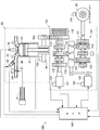
以下、本発明に係る車両用動力伝達システムの一実施形態について図面を参照しながら説明する。図1は、本発明に係る車両用動力伝達システム100の全体構成の概略を模式的に示すブロック図である。なお、本明細書において参照する各図は、本発明の理解を容易にするために一部の構成要素を誇張して表わすなど模式的に表している。このため、各構成要素間の寸法や比率などは異なっていることがある。この車両用動力伝達システム100は、二輪自動車両(所謂オートバイ)において原動機であるエンジン80で発生させた回転駆動力を駆動輪90に伝達する機械装置群であり、二輪自動車両におけるエンジン80の周辺(例えば、着座シートや燃料タンクの下方)に設けられる。
Hereinafter, an embodiment of a vehicle power transmission system according to the present invention will be described with reference to the drawings. FIG. 1 is a block diagram schematically showing an outline of the overall configuration of a vehicle
ここで、エンジン80は、図示しない二輪自動車両に搭載されて燃料の燃焼によって回転駆動力を発生させる原動機である。具体的には、エンジン80は、筒状に形成されたシリンダ81内に燃料と空気とからなる混合気を導入するとともに、この混合気を点火プラグ82によって点火して爆発させることによりピストン83をシリンダ81内で往復運動させてピストン83に連結されるクランクシャフト84に回転駆動力を発生させる所謂レシプロエンジンである。クランクシャフト84の回転駆動力は、クランクシャフト84の端部に取り付けられたプライマリードライブギア84aを介してクラッチ110に伝達される。なお、本実施形態においては、エンジン80は、所謂4ストロークエンジンを想定しているが、所謂2ストロークエンジンであってもよいことは当然である。また、本実施形態においては、エンジン80は、シリンダ81が3つ設けられた3気筒エンジンを想定しているが、4気筒以上のエンジンであってもよいことは当然である。
Here, the
このエンジン80における燃焼室を構成するシリンダ81には、吸気バルブ85を介して吸気管86が接続されている。吸気管86は、シリンダ81内に混合気を供給するための配管であり、シリンダ81内に供給する空気量を調整するスロットルバルブ87および同シリンダ81内に燃料を霧状にして供給(噴射)するインジェクタ88をそれぞれ備えている。これらのうち、点火プラグ82およびインジェクタ88は後述するECU140によって作動がそれぞれ制御されるとともに、スロットルバルブ87は車両の運転者によるアクセルグリップ91の手動操作によって作動する。
An
(車両用動力伝達システム100の構成)
車両用動力伝達システム100は、動力伝達装置101を備えている。動力伝達装置101は、エンジン80により発生された回転駆動力を複数の変速段で変速して伝達する機械装置であり、主として、クラッチ110およびトランスミッション130によって構成されている。
(Configuration of vehicle power transmission system 100)
The vehicle
クラッチ110は、エンジン80で発生させた回転駆動力の伝達経路上におけるエンジン80とトランスミッション130との間に配置されてエンジン80が発生させた回転駆動力をトランスミッション130に対して伝達および遮断を行なう機械装置である。このクラッチ110は、詳しくは、図2および図3にそれぞれ示すように、トランスミッション130から軸状に延びるメインシャフト115の一方(図示右側)の端部側に設けられている。
クラッチ110は、アルミニウム合金製のクラッチハウジング111を備えている。クラッチハウジング111は、有底円筒状に形成されており、クラッチ110の筐体の一部を構成する部材である。このクラッチハウジング111における図示左側側面には、プライマリードリブンギア112がトルクダンパ112aを介してリベット112bによって固着されている。プライマリードリブンギア112は、エンジン80の駆動により回転駆動するクランクシャフト84に一体的に連結されたプライマリードライブギア84aと噛合って回転駆動する。クラッチハウジング111における内周面には、複数枚のフリクションプレート113がクラッチハウジング111の軸線方向に沿って変位可能、かつ同クラッチハウジング111と一体回転可能な状態でスプライン嵌合によってそれぞれ保持されている。
The clutch 110 includes a
フリクションプレート113は、後述するクラッチプレート118に押し当てられる平板環状の部品であり、SPCC(冷間圧延鋼板)材からなる薄板材を環状に打ち抜いて成形されている。クラッチハウジング111の内部には、略フランジ状に形成されたクラッチハブ114がクラッチハウジング111と同心で配置されている。このクラッチハブ114の内周面には、クラッチハブ114の軸線方向に沿って多数のスプライン溝が形成されており、同スプライン溝にメインシャフト115がスプライン嵌合している。
The
メインシャフト115は、中空状に形成された軸体であり、一方(図示右側)の端部側がニードルベアリング115aを介してプライマリードリブンギア112およびクラッチハウジング111を回転自在に支持するとともに、前記スプライン嵌合するクラッチハブ114をナット115bを介して固定的に支持する。すなわち、クラッチハブ114は、メインシャフト115とともに一体的に回転する。一方、メインシャフト115における他方(図示左側)の端部側は、前記トランスミッション130に連結されている。
The
メインシャフト115の中空部には、一方(右側)の端部側にプッシュ部材116aが設けられるとともに同プッシュ部材116aに隣接してプッシュロッド116bがメインシャフト115の軸線方向に延びた状態で設けられている。これらのうち、プッシュ部材116aは、メインシャフト115の軸線方向に沿って延びる棒状部材であり、一方(図示左側)の端部がメインシャフト115の中空部に摺動自在に嵌合するとともに他方(図示右側)の端部がプレッシャプレート120に設けられたレリーズベアリング121に連結している。
In the hollow portion of the
プッシュロッド116bは、メインシャフト115における一方(図示左側)の端部側がクラッチアクチュエータ117に連結されているとともに、他方(図示右側)の端部がプッシュ部材116aを押圧している。クラッチアクチュエータ117は、図示しない油圧機構を介してプッシュロッド116bをメインシャフト115内で軸方向に沿って往復変位させることによりプッシュ部材116aを押す力を強めたり弱めたりするための原動機であり、ECU140によって作動が制御される電動モータで構成されている。
In the
この場合、ECU140は、クラッチアクチュエータ117をPWM(Pulse Width Modulation)制御によって作動を制御する。ここで、PWM制御とは、クラッチアクチュエータ117に対するパルス波のデューティ比を変化させる制御である。
In this case, the
クラッチハブ114の外周面には、複数枚のクラッチプレート118が前記フリクションプレート113を挟んだ状態で、クラッチハブ114の軸線方向に沿って変位可能、かつ同クラッチハブ114と一体回転可能な状態でスプライン嵌合によってそれぞれ保持されている。クラッチプレート118は、前記フリクションプレート113に押し当てられる平板環状の部品であり、SPCC(冷間圧延鋼板)材からなる薄板材を環状に打ち抜いて成形されている。これらのクラッチプレート118の内周部には、クラッチハブ114とスプライン嵌合させるための内歯状のスプラインが形成されている。
On the outer peripheral surface of the
一方、クラッチハブ114の内側には、それぞれ3つの筒状支持柱114a、ハブ側アシストカム部114bおよびハブ側スリッパカム部114cがプレッシャプレート120側(図示右側)に向って突出した状態でそれぞれ形成されている。これらのうち、3つの筒状支持柱114aは、プレッシャプレート120を支持するために柱状に延びた円筒状の部分であり、その内周部に雌ネジが形成されている。
On the other hand, three
3つのハブ側アシストカム部114bは、後述するプレッシャ側アシストカム部120bと協働してフリクションプレート113とクラッチプレート118との圧接力を増強するアシスト力を生じさせるための部分であり、図4(A)に示すように、クラッチハブ114の円周方向に沿って徐々にプレッシャプレート120側(図示右側)に突出する傾斜面でそれぞれ構成されている。この場合、3つのハブ側アシストカム部114bは、前記3つの筒状支持柱114aの各間に形成されている。
The three hub side assist
一方、3つのハブ側スリッパカム部114cは、図4(B)に示すように、後述するプレッシャ側スリッパカム部120cと協働してフリクションプレート113とクラッチプレート118とを早期に離隔させて半クラッチ状態に移行させるための部分であり、ハブ側アシストカム部114bとは周方向の反対側にハブ側アシストカム部114bと同じ方向に傾斜する傾斜面でそれぞれ構成されている。なお、図2においては、3つのうちの1つのハブ側アシストカム部114bを破線で示している。また、半クラッチ状態とは、クラッチ110におけるフリクションプレート113とクラッチプレート118が完全に密着する前の状態においてエンジン80の回転駆動力の一部が駆動輪90側に伝達される不完全な伝達状態のことである。
On the other hand, as shown in FIG. 4B, the three hub-side
プレッシャプレート120は、フリクションプレート113を押圧することによってこのフリクションプレート113とクラッチプレート118とを互いに密着させるための部品であり、アルミニウム材をクラッチプレート118の外径と略同じ大きさの外径の略円盤状に成形して構成されている。このプレッシャプレート120の盤面には、クラッチハブ114(図示左側)に向って張り出した状態でそれぞれ3つの筒状収容部120a、プレッシャ側アシストカム部120bおよびプレッシャ側スリッパカム部120cがそれぞれ形成されている。
The
これらのうち、3つの筒状収容部120aは、それぞれ前記3つの筒状支持柱114aおよびクラッチスプリング122を収容する部分であり周方向に延びる長孔状に形成されている。より具体的には、筒状収容部120a内には、クラッチハブ114の筒状支持柱114aが貫通した状態で配置されるとともにこの筒状支持柱114aの外側にクラッチスプリング122およびスプリングシート123がそれぞれ配置されている。クラッチスプリング122は、筒状収容部120a内に配置されてプレッシャプレート120をクラッチハブ114に向けて押圧する弾性力を発揮する弾性体であり、ばね鋼を螺旋状に巻いたコイルスプリングによって構成されている。すなわち、このクラッチスプリング122は、本発明に係る押圧弾性体に相当する。スプリングシート123は、筒状収容部120aの底部とクラッチスプリング122との間に配置される板状の部品であり、金属板を筒状収容部120aの底部に対応する平面視でC字状に形成されている。本実施形態においては、スプリングシート123は、厚さ0.5mmのばね鋼板で構成されている。
Among these, the three cylindrical
3つのプレッシャ側アシストカム部120bは、図4(A)に示すように、前記クラッチハブ114のハブ側アシストカム部114b上を摺動する部分であり、プレッシャプレート120の円周方向に沿って徐々にクラッチハブ114側(図示左側)に突出する傾斜面で構成されている。すなわち、ハブ側アシストカム部114bとプレッシャ側アシストカム部120bとでアシスト機構が構成されている。そして、このアシスト機構によって発生させるアシスト力によって容量(弾性係数)の低いクラッチスプリング122を用いることができる。
As shown in FIG. 4A, the three pressure side assist
一方、3つのプレッシャ側スリッパカム部120cは、図4(B)に示すように、前記ハブ側スリッパカム部114c上を摺動する部分であり、プレッシャ側アシストカム部120bとは周方向の反対側にプレッシャ側アシストカム部120bと同じ方向に延びる傾斜面でそれぞれ構成されている。すなわち、ハブ側スリッパカム部114cとプレッシャ側スリッパカム部120cとでスリッパ機構が構成されている。
On the other hand, as shown in FIG. 4B, the three pressure side
このプレッシャプレート120は、クラッチハブ114に3つの取付ボルト124によって取り付けられている。具体的には、プレッシャプレート120は、筒状収容部120a内にクラッチハブ114の筒状支持柱114a、スプリングシート123およびクラッチスプリング122がそれぞれ配置された状態で取付ボルト124が筒状支持柱114aにストッパ部材125を介して締め付けられて固定されている。この場合、ストッパ部材125は、プレッシャプレート120がクラッチハブ114に対して離隔する方向に変位する量を規制するための金属製の部材であり、平面視で略三角形状に形成されている。これにより、プレッシャプレート120は、クラッチハブ114に対して近接および離隔する方向に変位可能な状態で取り付けられる。
The
そして、このクラッチ110内には、所定量のクラッチオイル(図示しない)が充填されている。クラッチオイルは、主として、フリクションプレート113とクラッチプレート118との間に供給されてこれらの間で生じる摩擦熱の吸収や摩擦材の摩耗を防止する。すなわち、このクラッチ110は、所謂湿式多板摩擦クラッチである。
The clutch 110 is filled with a predetermined amount of clutch oil (not shown). The clutch oil is mainly supplied between the
トランスミッション130は、エンジン80から発生した回転駆動力を複数の変速段(例えば、4段変速)で変速して駆動輪90に伝達するための機械装置である。このトランスミッション130は、クラッチ110を介してエンジン80のクランクシャフト84に繋がるメインシャフト115とこのメインシャフト115と平行に延びて駆動輪90に繋がるカウンターシャフト131との間に互いに変速比の異なる複数の変速段を構成する複数のギア列が設けられて構成されている。
The
このメインシャフト115とカウンターシャフト131との間に設けられた複数のギア列は、それぞれメインシャフト115に設けられた複数の駆動側ギア132とカウンターシャフト131に設けられた複数の従動側ギア133とでそれぞれ構成されており、これらの駆動側ギア132と従動側ギア133とは、互いに対向するギア同士が対を構成して常に噛み合っている。この場合、これらの駆動側ギア132および従動側ギア133のうちの一部の駆動側ギア132および従動側ギア133にはシフトフォーク134が挿し込まれており、このシフトフォーク134によってメインシャフト115上およびカウンターシャフト131上をそれぞれスライド変位して駆動側ギア132同士および従動側ギア133同士が互いにドッグクラッチ方式で連結および分離して変速段が形成される。
A plurality of gear trains provided between the
シフトフォーク134は、スライド変位可能な駆動側ギア132および従動側ギア133を軸線方向に押圧してスライドさせて変速段を形成させるためのフォーク状の部品であり、シフトドラム135に支持されている。シフトドラム135は、シフトフォーク134をメインシャフト115およびカウンターシャフト131に沿って往復変位させるための円柱状の部品である。このシフトドラム135は、シフトアクチュエータ136によって回転駆動される。
The
シフトアクチュエータ136は、シフトドラム135を回転駆動させることによって回転角度に応じた駆動側ギア132および従動側ギア133からなる変速段の組替えを行うための原動機であり、ECU140によって作動が制御される電動モータで構成されている。この場合、ECU140は、シフトアクチュエータ136を前記PWM制御によって作動を制御する。
The
なお、図1においては、メインシャフト115の駆動側ギア132とカウンターシャフト131の従動側ギア133とは互いに直接噛合っているが、構成の説明上敢えてメインシャフト115とカウンターシャフト131との間にシフトドラムを配置して互いに離れた位置に配置して示している。また、本実施形態においては、トランスミッション130は、1段〜4段およびニュートラルの5つの変速段を備えている。
In FIG. 1, the driving
ECU140(Engine Control Unit)は、CPU、ROM、RAMなどからなるマイクロコンピュータによって構成されており、ROMなどに予め記憶された図示しない制御プログラムに従って車両用動力伝達システム100の作動を含む車両全体の作動を総合的に制御する。このECU140は、エンジン80および動力伝達装置101に車両用動力伝達システム100の作動制御に必要な情報を取得するための各種センサが接続されている。
The ECU 140 (Engine Control Unit) is configured by a microcomputer including a CPU, a ROM, a RAM, and the like, and the operation of the entire vehicle including the operation of the vehicle
具体的には、ECU140には、回転数センサ150、車速センサ151、シフトアクチュエータセンサ152、シフトポジションセンサ153、クラッチアクチュエータセンサ154およびスロットル開度センサ155がそれぞれ接続されている。この場合、回転数センサ150は、エンジン80の回転数をクランクシャフト84の回転数を介して検出する。また、車速センサ151は、本実施形態に係る二輪自動車両の車速を後輪である駆動輪90の回転数を介して検出する。
Specifically, the
また、シフトアクチュエータセンサ152は、シフトアクチュエータ136の駆動量をシフトアクチュエータ136の回転角度を介して検出する。また、シフトポジションセンサ153は、トランスミッション130の変速段を検出する。また、クラッチアクチュエータセンサ154は、クラッチアクチュエータ117の駆動量をクラッチアクチュエータ117の回転角度を介して検出する。また、スロットル開度センサ155は、スロットルバルブ87の開度を検出する。
The
したがって、ECU140は、これらの各種センサからの検出信号に基づいてエンジン80および動力伝達装置101の各作動、より具体的には、点火プラグ82、インジェクタ88、クラッチアクチュエータ117およびシフトアクチュエータ136の各作動を制御してエンジン80の燃焼制御、クラッチ110の接続および切断の制御、およびトランスミッション130におけるシフトアップおよびシフトダウンの各変速動作の制御をそれぞれ実行する。すなわち、ECU140は、本発明に係る制御装置に相当する。
Therefore,
(車両用動力伝達システム100の作動)
次に、上記のように構成した車両用動力伝達システム100の作動について説明する。この車両用動力伝達システム100は、前記したように二輪自動車両における着座シートや燃料タンクの下方に配置されて、車両が走行中または走行可能な状態で一時的に停車している場合においてECU140の作動制御によって車速に応じたシフトアップ制御またはシフトダウン制御を自動的に行う。
(Operation of vehicle power transmission system 100)
Next, the operation of the vehicle
そして、ECU140は、前記シフトアップ制御時におけるクラッチON状態への移行時において、ハブ側アシストカム部114bとプレッシャ側アシストカム部120bとによって生じるアシスト力を抑えたクラッチON状態への移行制御を行う。この場合、ECU140によるシフトアップ制御の実行は、回転数センサ150、車速センサ151、シフトアクチュエータセンサ152、シフトポジションセンサ153、クラッチアクチュエータセンサ154およびスロットル開度センサ155からの各検出信号に基づいてECU140が二輪自動車両の発進やシフトアップの必要性を検出して自動的に実行する。
Then, the
シフトアップ制御を行う場合、ECU140は、まず、クラッチ110をクラッチOFF状態とする。具体的には、ECU140は、クラッチアクチュエータ117の作動を制御してプッシュロッド116bをレリーズベアリング121側にスライド変位させてプッシュ部材116aでレリーズベアリング121を押圧する。これにより、クラッチ110は、プレッシャプレート120がフリクションプレート113から離隔するため、フリクションプレート113とクラッチプレート118とが離隔してトランスミッション130に対してエンジン80からの駆動力が遮断されたクラッチOFFの状態となる。すなわち、クラッチ110をクラッチOFFの状態とするためにクラッチアクチュエータ117がプッシュロッド116bおよびプッシュ部材116a、レリーズベアリング121を介してプレッシャプレート120を押圧する力が本発明におけるクラッチOFF押圧力である。
When performing the upshift control, the
このクラッチOFF状態とする過程においては、図4(B)に示すように、メインシャフト115の回転数がプライマリードリブンギア112の回転数を上回った場合(c参照)、すなわち、クラッチ110にバックトルクが作用した場合においては、クラッチハブ114に形成されたハブ側スリッパカム部114cにプレッシャプレート120に形成されたプレッシャ側スリッパカム部120cが乗り上げるカム作用によってプレッシャプレート120がクラッチハブ114に対して相対的に回転変位しながら互いに離隔する方向に変位(d参照)して押圧力が小さくなるスリッパ機能が作用する。
In the process of setting the clutch OFF state, as shown in FIG. 4B, when the rotation speed of the
次に、ECU140は、トランスミッション130において変速段を形成する。具体的には、ECU140は、シフトアクチュエータ136の作動を制御してシフトドラム135を回転変位させることにより駆動側ギア132と従動側ギア133とを組み合わせて車速に応じた所定の変速比からなる変速段(1段から4段)を形成する。
Next,
次に、ECU140は、クラッチ110をクラッチONの状態とする。具体的には、ECU140は、クラッチアクチュエータ117の作動を制御してプッシュロッド116bをレリーズベアリング121から離隔する側(図示左側)にスライド変位させる。この場合、ECU140は、プレッシャプレート120の位置がフリクションプレート113とクラッチプレート118とが密着して実質的にクラッチON状態となる位置に達しない範囲でクラッチアクチュエータ117の回転量を制御してプッシュロッド116bを後退(図示左側に変位)させる。
Next, the
また、ECU140は、プレッシャプレート120に付与するクラッチOFF押圧力をクラッチスプリング122の弾性力よりも弱めるようにクラッチアクチュエータ117の回転量を制御することによってプッシュロッド116bを後退させる。これらにより、プレッシャプレート120は、前記クラッチOFF押圧力が弱まるため、クラッチスプリング122の弾性力によってフリクションプレート113側に変位してフリクションプレート113の押圧を開始する。この結果、クラッチ110は、クラッチOFF状態から半クラッチ状態に移行する。
The
このクラッチOFF状態から半クラッチ状態に移行させる場合において、ECU140は、図5に示すように、プッシュロッド116bを後退させるための負側のPWM信号をクラッチアクチュエータ117に出力する。本実施形態においては、ECU140は、負側に大きな変位量となるPWM信号を出力した後(t1参照)、負側において継時的に変位量が小さくなるPWM信号を出力する(t2参照)。この場合、ECU140は、プレッシャプレート120の位置がフリクションプレート113とクラッチプレート118とが近接して半クラッチ状態とすることができる位置に位置するようにPWM信号をクラッチアクチュエータ117に出力する。
When shifting from the clutch-off state to the half-clutch state, the
また、この場合、負側において継時的に変位量が小さくなるPWM信号とは、クラッチが半クラッチ状態に移行した場合に生じるアシスト力によって変位するプレッシャプレート120の変位速度よりも遅い速度でプレッシャプレート120を変位させるものである。一方、負側に大きな変位量となるPWM信号とは、前記した負側において継時的に変位量が小さくなるPWM信号での変位速度よりも速い速度でプレッシャプレート120を変位させるものである。これにより、ECU140は、クラッチ110を早期に半クラッチ状態に移行させることができるとともに半クラッチ状態に移行した直後の駆動力の伝達を円滑に開始させることができる。
Further, in this case, the PWM signal whose displacement is gradually reduced on the negative side is a pressure that is slower than the displacement speed of the
次に、クラッチ110が半クラッチ状態に移行すると(t2参照)、図4(A)に示すように、プライマリードリブンギア112の回転数がメインシャフト115の回転数を上回った場合(a参照)、クラッチハブ114に形成されたハブ側アシストカム部114bにプレッシャプレート120に形成されたプレッシャ側アシストカム部120bcが引き込まれるカム作用によってプレッシャプレート120がクラッチハブ114に対して相対的に回転変位しながら互いに接近する方向に変位(b参照)してアシスト力が発生するアシスト機能が作用する。この場合、アシスト力は、指数関数的に増加する(t2〜t4参照)。
Next, when the clutch 110 shifts to the half-clutch state (see t2), as shown in FIG. 4A, when the rotational speed of the primary driven
この場合、ECU140は、アシスト力が発生した後で最大値に達するまでのアシスト力の過程(t2〜t4参照)においてアシスト力の発生が比較的小さい前半段階においては、プッシュロッド116bを後退させる力をアシスト力の指数関数的増加に対応して経時的に徐々に小さくなるようにクラッチアクチュエータ117の作動を制御する(t2〜t3参照)。具体的には、ECU140は、クラッチアクチュエータ117に対して負側において継時的に変位量が小さくなるPWM信号を出力する。
In this case, the
すなわち、ECU140は、アシスト力の発生過程における前半段階(t2〜t3参照)においては、プレッシャプレート120に生じるアシスト力に対してこのアシスト力に抗する抗アシスト力をプレッシャプレート120に付与するようにクラッチアクチュエータ117の作動を制御する。この場合、抗アシスト力は、クラッチハブ114側(つまり、負側)に変位するプレッシャプレート120の変位力と同クラッチハブ114側に作用するアシスト力との差である。したがって、ECU140は、アシスト力によって変位するプレッシャプレート120よりも遅い速度でプレッシャプレート120を変位させるようにクラッチアクチュエータ117の作動を制御することで抗アシスト力を発生させることができる。
That is, in the first half of the assist force generation process (see t2 to t3 ), the
これにより、プレッシャプレート120は、アシスト力によってクラッチハブ114側に変位しようとするが、プッシュロッド116bによって変位が阻害されて変位量が抑えられる。この結果、クラッチ110は、エンジン80の駆動力が徐々に伝達されて急激な伝達が抑えられる。このプレッシャプレート120の変位の負荷となるプッシュロッド116bを介したクラッチアクチュエータ117からの抵抗力が本発明における抗アシスト力である。この場合、抗アシスト力は、プレッシャプレート120に作用するアシスト力未満の力である。
As a result, the
次いで、アシスト力の発生過程(t2〜t4参照)においてアシスト力が大きく増大する後半段階(t3〜t4参照)においては、ECU140は、プッシュロッド116bの後退に代えてレリーズベアリング121側に前進させるようにクラッチアクチュエータ117の作動を制御する。具体的には、ECU140は、アシスト力の発生過程の中間時点(t3参照)でプッシュロッド116bをレリーズベアリング121側に前進させるようにクラッチアクチュエータ117の作動を制御する。この場合、ECU140は、プレッシャプレート120を前進させるために付与する力、すなわち、抗アシスト力がプレッシャプレート120に作用するアシスト力未満の力となるようにクラッチアクチュエータ117の作動を制御する。
Next, in the latter half stage (see t3 to t4) in which the assist force greatly increases in the assist force generation process (see t2 to t4), the
また、この場合、ECU140は、アシスト力の指数関数的増加に対応して抗アシスト力が指数関数的に増加するようにクラッチアクチュエータ117の作動を制御する(t3〜t4参照)。具体的には、ECU140は、クラッチアクチュエータ117に対して正側において継時的に変位量が大きくなるPWM信号を出力する。
In this case, the
これにより、プレッシャプレート120は、アシスト力によって更に強力にクラッチハブ114側に変位しようとするが、プッシュロッド116bに作用する抗アシスト力によって変位が阻害されて変位量が抑えられる。この結果、クラッチ110は、エンジン80の駆動力が徐々に伝達されて急激な伝達が抑えられる。また、クラッチ110は、アシスト力の増加に応じて抗アシスト力を増加させているため、駆動力の伝達を一定の割合で増加させて急激な伝達を抑えることができる。また、クラッチ110は、抗アシスト力がアシスト力未満であるため、プレッシャプレート120は徐々にクラッチハブ114側に変位してクラッチON状態に移行する。
As a result, the
次いで、アシスト力が最大値に達した場合(t4参照)には、ECU140は、クラッチ110が半クラッチ状態である間プッシュロッド116bを前進させる力を一定に保つようにクラッチアクチュエータ117の作動を制御する。本実施形態においては、ECU140は、アシスト力が最大値に達した際の抗アシスト力を最大値として維持するようにクラッチアクチュエータ117の作動を制御する。具体的には、ECU140は、クラッチアクチュエータ117に対して正側において変位量が一定のPWM信号を出力し続ける。これにより、クラッチ110は、プレッシャプレート120がアシスト力に徐々に押されながらクラッチハブ114側に変位することにより、エンジン80の駆動力が徐々に伝達されて急激な伝達が抑えられる。
Next, when the assist force reaches the maximum value (see t4), the
なお、プッシュロッド116bを後退させた時点からプッシュロッド116bを前進させて抗アシスト力が最大値となる時点までの時間(t1〜t4参照)は約0.1〜0.2秒である。また、プレッシャプレート120に付与する抗アシスト力の大きさ、付与タイミングや継時的変化および付与時間は、クラッチ110の製造前に予めアシスト力について力の大きさ、発生のタイミング、発生時間をそれぞれ測定しておくことでこれらの情報に基づいてクラッチアクチュエータ117の作動を制御するPWM信号をECU140のROMなどの記憶装置に設定しておくことができる。
Note that the time (see t1 to t4) from when the
次いで、クラッチ110が半クラッチ状態を脱する場合には、ECU140は、プッシュロッド116bの前進を中断するようにクラッチアクチュエータ117の作動を制御する。この場合、ECU140は、プッシュロッド116bの前進に代えて一旦後進させた後、プッシュロッド116bの変位を停止するようにクラッチアクチュエータ117の作動を制御するとよい(t5参照)。これにより、クラッチ110は、プレッシャプレート120がクラッチスプリング122の弾性力によってクラッチハブ114側に変位してフリクションプレート113とクラッチプレート118とが完全に密着してクラッチONの状態に移行する。この結果、クラッチ110は、トランスミッション130にて新たに形成された変速段にエンジン80からの駆動力を伝達して二輪自動車両を走行させることができる。
Next, when the clutch 110 leaves the half-clutch state, the
なお、クラッチ110は、半クラッチ状態を脱する境界付近で実質的にクラッチON状態となった段階で、プライマリードリブンギア112の回転数とメインシャフト115の回転数が同一となるため、伝達されるエンジン80からの駆動力が若干低下した後一定値に維持される。また、図5においては、本発明に係る抗アシスト力をプレッシャプレート120に付与しない場合におけるクラッチアクチュエータ117の回転角度、クラッチアクチュエータ117へのPWM信号およびクラッチ110が伝達する駆動力をそれぞれ二点鎖線で示している。この場合、本発明に係る抗アシスト力をプレッシャプレート120に付与しない場合におけるクラッチアクチュエータ117へのPWM信号は、本発明に対する比較例としてプレッシャプレート120を後退させた後、徐々に後退量を減少させた場合を示している。
The clutch 110 is transmitted because the rotational speed of the primary driven
上記作動説明からも理解できるように、上記実施形態によれば、車両用動力伝達システム100は、クラッチ110を駆動力の伝達状態であるクラッチON状態と駆動力の遮断状態であるクラッチOFF状態とするクラッチアクチュエータ117およびこのクラッチアクチュエータ117の作動を制御する制御装置であるECU140を備えるとともに、このECU140がクラッチアクチュエータ117の作動を制御してプレッシャプレート120に付与するクラッチOFF押圧力をクラッチスプリング122の弾性力よりも弱めつつアシスト力未満の力でアシスト力に抗する抗アシスト力を付与してアシスト力の増加を抑えている。これにより、車両用動力伝達システム100は、クラッチ110が従来技術に比べてゆっくり円滑にクラッチON状態に移行するため、運転者は違和感なく車両の運転をすることができる。
As can be understood from the above description of operation, according to the above embodiment, the vehicle
さらに、本発明の実施にあたっては、上記実施形態に限定されるものではなく、本発明の目的を逸脱しない限りにおいて種々の変更が可能である。 Furthermore, in carrying out the present invention, the present invention is not limited to the above embodiment, and various modifications can be made without departing from the object of the present invention.
例えば、上記実施形態においては、車両用動力伝達システム100は、クラッチ110が半クラッチ状態となる直前にプレッシャプレート120の変位速度を半クラッチ状態に移行した場合に生じるアシスト力によって変位するプレッシャプレート120の変位速度よりも遅い速度にすることにより、クラッチ110が半クラッチ状態に移行する直前から抗アシスト力を付与するように構成した。しかし、車両用動力伝達システム100は、クラッチ110が半クラッチ状態に移行した後にプレッシャプレート120に対して抗アシスト力を付与するように構成することもできる。
For example, in the above-described embodiment, the vehicle
また、上記実施形態においては、ECU140は、アシスト力の発生過程における中間時点でプレッシャプレート120に正側の抗アシスト力を付与するようにクラッチアクチュエータ117の作動を制御した。しかし、ECU140は、アシスト力の発生過程における中間時点よりも前または後にプレッシャプレート120に正側の抗アシスト力を付与するようにクラッチアクチュエータ117の作動を制御してもよいし、アシスト力が発生する前にプレッシャプレート120に正側の抗アシスト力を付与するようにクラッチアクチュエータ117の作動を制御してもよい。また、ECU140は、アシスト力の発生過程においてプレッシャプレート120に負側の抗アシスト力を付与するようにクラッチアクチュエータ117の作動を制御してもよい。
In the above embodiment, the
また、上記実施形態においては、ECU140は、プレッシャプレート120に付与する抗アシスト力を経時的に増加するようにクラッチアクチュエータ117の作動を制御した。しかし、ECU140は、プレッシャプレート120に付与する抗アシスト力を経時的に一定にするようにクラッチアクチュエータ117の作動を制御してもよい。
In the above embodiment, the
また、上記実施形態においては、ECU140は、クラッチ110がクラッチON状態に移行するまでの間、プレッシャプレート120に抗アシスト力を付与するようにクラッチアクチュエータ117の作動を制御した。しかし、ECU140は、クラッチ110がクラッチON状態に移行する前(すなわち、半クラッチ状態)やクラッチON状態に移行後までプレッシャプレート120に抗アシスト力を付与するようにクラッチアクチュエータ117の作動を制御することもできる。
In the above embodiment, the
また、上記実施形態においては、ECU140は、クラッチON状態に移行させる際に予め設定した1つの経時的変化で抗アシスト力をプレッシャプレート120に付与するようにクラッチアクチュエータ117の作動を制御した。しかし、ECU140は、エンジン80の回転数やトルク、クラッチアクチュエータ117の回転位置、トランスミッション130の変速段の状況または二輪自動車両の車速などの状況に応じて互いに異なる複数の抗アシスト力を選択的にプレッシャプレート120に付与することができる。
Further, in the above embodiment, the
例えば、ECU140は、エンジン80の回転数やトルク、クラッチアクチュエータ117の回転位置、トランスミッションの変速段の状況または二輪自動車両の車速ごとに複数の抗アシスト力を関連付けた抗アシスト力選択テーブルをROMなどの記憶装置に予め記憶しておく。そして、ECU140は、エンジン80の回転数やトルク、クラッチアクチュエータ117の回転位置、トランスミッションの変速段の状況または二輪自動車両の車速などの状況に応じて抗アシスト力選択テーブルから最適なまたは関連付けられた抗アシスト力をプレッシャプレート120に付与するようにクラッチアクチュエータ117の作動を制御することができる。
For example, the
また、上記実施形態においては、車両用動力伝達システム100は、クラッチ110におけるメインシャフト115を進退させるためにクラッチアクチュエータ117を備えるとともに、トランスミッション130におけるシフトドラム135を回転駆動させるためにシフトアクチュエータ136を備えて構成した。しかし、車両用動力伝達システム100は、クラッチ110におけるメインシャフト115とトランスミッション130におけるシフトドラム135とを1つの電動モータで駆動させることもできる。
In the above embodiment, the vehicle
また、上記実施形態においては、車両用動力伝達システム100は、アシスト機構およびスリッパ機構をそれぞれ有したクラッチ110を備えて構成した。しかし、車両用動力伝達システム100は、少なくともアシスト機構を有したクラッチ110を備えて構成されていればよく、スリッパ機構を省略することができる。
In the above embodiment, the vehicle
80…エンジン、81…シリンダ、82…点火プラグ、83…ピストン、84…クランクシャフト、84a…プライマリードライブギア、85…吸気バルブ、86…吸気管、87…スロットルバルブ、88…インジェクタ、
90…駆動輪、
100…車両用動力伝達システム、
101…動力伝達装置、101…動力伝達装置、
110…クラッチ、111…クラッチハウジング、112…プライマリードリブンギア、112a…トルクダンパ、112b…リベット、113…フリクションプレート、114…クラッチハブ、114a…筒状支持柱、114b…ハブ側アシストカム部、114c…ハブ側スリッパカム部、115…メインシャフト、115a…ニードルベアリング、115b…ナット、116a…プッシュ部材、116b…プッシュロッド、117…クラッチアクチュエータ、118…クラッチプレート、
120…プレッシャプレート、120a…筒状収容部、120b…プレッシャ側アシストカム部、120b…プレッシャ側スリッパカム部、121…レリーズベアリング、122…クラッチスプリング、123…スプリングシート、124…取付ボルト、125…ストッパ部材、
130…トランスミッション、131…カウンターシャフト、132…駆動側ギア、133…従動側ギア、134…シフトフォーク、135…シフトドラム、136…シフトアクチュエータ、
140…ECU、
150…回転数センサ、151…車速センサ、152…シフトアクチュエータセンサ、153…シフトポジションセンサ、154…クラッチアクチュエータセンサ、155…スロットル開度センサ。
DESCRIPTION OF
90 ... drive wheels,
100: Vehicle power transmission system,
101 ... Power transmission device, 101 ... Power transmission device,
DESCRIPTION OF
DESCRIPTION OF
DESCRIPTION OF
140 ... ECU,
DESCRIPTION OF
Claims (6)
前記エンジンから伝達される前記駆動力によって回転駆動するフリクションプレートに対向配置されるクラッチプレートを保持して前記駆動力を前記トランスミッションに伝達するクラッチハブ、および同クラッチハブに対して接近または離隔可能かつ相対回転可能な状態で隣接配置されて前記フリクションプレートまたは前記クラッチプレートを押圧弾性体によって弾性的に押圧するプレッシャプレートを備えて前記エンジンから伝達される前記駆動力を前記トランスミッションに伝達または遮断するクラッチとを備え、
前記クラッチは、
前記エンジンの前記駆動力の伝達状態への移行時に前記クラッチハブと前記プレッシャプレートとの間で相対回転が生じたとき、前記フリクションプレートと前記クラッチプレートとの圧接力を増加させるアシスト力を生じさせるための傾斜面からなるハブ側アシストカム部およびプレッシャ側アシストカム部を前記クラッチハブおよび前記プレッシャプレートにそれぞれ有した車両用動力伝達システムにおいて、
前記クラッチを前記駆動力の遮断状態とするために前記押圧弾性体の弾性力に抗して前記プレッシャプレートを前記フリクションプレートまたは前記クラッチプレートから離隔させるクラッチOFF押圧力を前記プレッシャプレートに付与するクラッチアクチュエータと、
前記クラッチアクチュエータの作動を制御して前記クラッチにおける前記駆動力の伝達および遮断を制御する制御装置とを備え、
前記制御装置は、
前記クラッチを前記駆動力の伝達状態に移行させる際に、前記クラッチアクチュエータの作動を制御して前記プレッシャプレートに付与する前記クラッチOFF押圧力を前記押圧弾性体の弾性力よりも弱めつつ前記プレッシャプレートに前記アシスト力未満の力で同アシスト力に抗する抗アシスト力を付与することにより前記アシスト力の増加を抑えることを特徴とする車両用動力伝達システム。 A transmission for transmitting a driving force of an engine mounted on the vehicle to the driving wheels of the vehicle while changing a rotation speed;
A clutch hub that holds a clutch plate disposed opposite to a friction plate that is rotationally driven by the driving force transmitted from the engine and transmits the driving force to the transmission, and is capable of approaching or separating from the clutch hub; A clutch that is disposed adjacent to each other in a relatively rotatable state and includes a pressure plate that elastically presses the friction plate or the clutch plate by a pressing elastic body, and transmits or interrupts the driving force transmitted from the engine to the transmission. And
The clutch is
When relative rotation occurs between the clutch hub and the pressure plate at the time of transition of the engine to the transmission state of the driving force, an assist force that increases the pressure contact force between the friction plate and the clutch plate is generated. In the vehicle power transmission system having a hub-side assist cam portion and a pressure-side assist cam portion comprising inclined surfaces for the clutch hub and the pressure plate, respectively.
A clutch that applies a clutch OFF pressing force to the pressure plate that separates the pressure plate from the friction plate or the clutch plate against the elastic force of the pressing elastic body in order to place the clutch in a state where the driving force is cut off. An actuator,
A control device for controlling the transmission and disconnection of the driving force in the clutch by controlling the operation of the clutch actuator;
The controller is
When the clutch is shifted to the transmission state of the driving force, the pressure plate while controlling the operation of the clutch actuator and applying the clutch OFF pressing force applied to the pressure plate to be weaker than the elastic force of the pressing elastic body. An increase in the assist force is suppressed by applying an anti-assist force against the assist force to a force less than the assist force.
前記制御装置は、
前記クラッチアクチュエータの作動を制御して前記クラッチが半クラッチ状態に入る以前に前記プレッシャプレートに前記抗アシスト力を付与することを特徴とする車両用動力伝達システム。 The vehicle power transmission system according to claim 1,
The controller is
A vehicle power transmission system that controls the operation of the clutch actuator to apply the anti-assist force to the pressure plate before the clutch enters a half-clutch state.
前記制御装置は、
前記クラッチアクチュエータの作動を制御して前記アシスト力が発生した後でかつ前記アシスト力が最大値となる前に前記プレッシャプレートに対して前記アシスト力に向かう向きの前記抗アシスト力を付与することを特徴とする車両用動力伝達システム。 In the vehicle power transmission system according to claim 1 or 2,
The controller is
The anti-assist force in the direction toward the assist force is applied to the pressure plate after the assist force is generated by controlling the operation of the clutch actuator and before the assist force reaches the maximum value. A vehicle power transmission system.
前記制御装置は、
前記クラッチアクチュエータの作動を制御して前記アシスト力が発生した後最大値に達するまでの間の中間時に前記プレッシャプレートに前記抗アシスト力を付与することを特徴とする車両用動力伝達システム。 In the vehicle power transmission system according to claim 3,
The controller is
The vehicle power transmission system, wherein the anti-assist force is applied to the pressure plate during an intermediate period between the generation of the assist force and the maximum value after the operation of the clutch actuator is controlled.
前記制御装置は、
前記クラッチアクチュエータの作動を制御して前記プレッシャプレートに付与する前記抗アシスト力を経時的に増加させることを特徴とする車両用動力伝達システム。 The vehicle power transmission system according to any one of claims 1 to 4,
The controller is
A vehicular power transmission system that controls the operation of the clutch actuator to increase the anti-assist force applied to the pressure plate over time.
前記制御装置は、
前記クラッチアクチュエータの作動を制御して前記プレッシャプレートに対する前記抗アシスト力の付与を前記駆動力を完全に伝達するクラッチON移行時まで行うことを特徴とする車両用動力伝達システム。 The vehicle power transmission system according to any one of claims 1 to 5,
The controller is
A vehicle power transmission system that controls the operation of the clutch actuator to apply the anti-assist force to the pressure plate until the clutch is turned on to completely transmit the driving force.
Priority Applications (3)
| Application Number | Priority Date | Filing Date | Title |
|---|---|---|---|
| JP2015097106A JP6376662B2 (en) | 2015-05-12 | 2015-05-12 | Power transmission system for vehicles |
| US15/137,738 US9546697B2 (en) | 2015-05-12 | 2016-04-25 | Vehicle power transmission system |
| EP16167073.2A EP3096038B1 (en) | 2015-05-12 | 2016-04-26 | Vehicle power transmission system |
Applications Claiming Priority (1)
| Application Number | Priority Date | Filing Date | Title |
|---|---|---|---|
| JP2015097106A JP6376662B2 (en) | 2015-05-12 | 2015-05-12 | Power transmission system for vehicles |
Publications (3)
| Publication Number | Publication Date |
|---|---|
| JP2016211688A JP2016211688A (en) | 2016-12-15 |
| JP2016211688A5 JP2016211688A5 (en) | 2017-12-07 |
| JP6376662B2 true JP6376662B2 (en) | 2018-08-22 |
Family
ID=55854637
Family Applications (1)
| Application Number | Title | Priority Date | Filing Date |
|---|---|---|---|
| JP2015097106A Active JP6376662B2 (en) | 2015-05-12 | 2015-05-12 | Power transmission system for vehicles |
Country Status (3)
| Country | Link |
|---|---|
| US (1) | US9546697B2 (en) |
| EP (1) | EP3096038B1 (en) |
| JP (1) | JP6376662B2 (en) |
Families Citing this family (11)
| Publication number | Priority date | Publication date | Assignee | Title |
|---|---|---|---|---|
| JP6147127B2 (en) * | 2013-07-25 | 2017-06-14 | 株式会社エフ・シー・シー | Saddle riding |
| JP2018141480A (en) * | 2017-02-27 | 2018-09-13 | ヤマハ発動機株式会社 | Motor cycle |
| IT201700031815A1 (en) * | 2017-03-22 | 2018-09-22 | Adler Spa | Clutch, in particular clutch for motorcycles, and relative mounting method |
| JP6498722B2 (en) * | 2017-06-01 | 2019-04-10 | 株式会社エフ・シー・シー | Clutch device |
| JP6710709B2 (en) * | 2018-01-10 | 2020-06-17 | 本田技研工業株式会社 | Multi-plate friction clutch |
| DE102018103064A1 (en) * | 2018-02-12 | 2019-08-14 | Schaeffler Technologies AG & Co. KG | Coupling unit with torsional vibration damper as coupling carrier, hybrid module with coupling unit |
| CN109163029A (en) * | 2018-09-05 | 2019-01-08 | 庆安集团有限公司 | One bulb ramp type double rolling key clutch |
| CN109838471A (en) * | 2019-03-15 | 2019-06-04 | 黄山奔马集团有限公司 | A kind of adaptive normally closed type clutch of motorcycle |
| WO2024009773A1 (en) * | 2022-07-05 | 2024-01-11 | 株式会社エフ・シー・シー | Clutch device |
| JP7255009B1 (en) | 2022-07-06 | 2023-04-10 | 株式会社エフ・シー・シー | Clutch device and motorcycle |
| JP7291309B1 (en) * | 2022-07-15 | 2023-06-14 | 株式会社エフ・シー・シー | Clutch device and motorcycle |
Family Cites Families (11)
| Publication number | Priority date | Publication date | Assignee | Title |
|---|---|---|---|---|
| GB508088A (en) | 1937-12-23 | 1939-06-23 | Johann Nikolaus Kiep | Improvements in variable-speed power-transmission mechanism |
| US2208111A (en) | 1938-04-28 | 1940-07-16 | Backstrom Adolph | Clutch mechanism |
| JP3378097B2 (en) * | 1994-09-29 | 2003-02-17 | 本田技研工業株式会社 | Friction clutch |
| ES2161306T3 (en) | 1995-03-03 | 2001-12-01 | Bayerische Motoren Werke Ag | COMMAND DEVICE FOR REGULATING THE CLOSURE PROCESS OF A SEPARATION CLUTCH FOR AUTOMOBILE VEHICLES. |
| JP4527055B2 (en) * | 2005-12-28 | 2010-08-18 | 株式会社エフ・シー・シー | Power transmission device |
| US8113329B2 (en) | 2007-11-21 | 2012-02-14 | Yamaha Hatsudoki Kabushiki Kaisha | Friction clutch and vehicle equipped with the same |
| JP4922226B2 (en) | 2008-03-28 | 2012-04-25 | 本田技研工業株式会社 | Vehicle clutch |
| JP4929246B2 (en) * | 2008-07-31 | 2012-05-09 | 本田技研工業株式会社 | Multi-plate clutch |
| JP5368253B2 (en) * | 2008-10-30 | 2013-12-18 | ヤマハ発動機株式会社 | Twin clutch transmission and vehicle equipped with the same |
| JP5995439B2 (en) * | 2011-12-28 | 2016-09-21 | 株式会社エフ・シー・シー | Power transmission device |
| JP5896013B2 (en) * | 2012-03-07 | 2016-03-30 | トヨタ自動車株式会社 | Power transmission device |
-
2015
- 2015-05-12 JP JP2015097106A patent/JP6376662B2/en active Active
-
2016
- 2016-04-25 US US15/137,738 patent/US9546697B2/en active Active
- 2016-04-26 EP EP16167073.2A patent/EP3096038B1/en active Active
Also Published As
| Publication number | Publication date |
|---|---|
| EP3096038A1 (en) | 2016-11-23 |
| EP3096038B1 (en) | 2020-02-26 |
| US9546697B2 (en) | 2017-01-17 |
| US20160333943A1 (en) | 2016-11-17 |
| JP2016211688A (en) | 2016-12-15 |
Similar Documents
| Publication | Publication Date | Title |
|---|---|---|
| JP6376662B2 (en) | Power transmission system for vehicles | |
| JP6501354B2 (en) | Power transmission system for vehicles | |
| US10035512B2 (en) | Transmission and shift control system | |
| US10352373B2 (en) | Multiple plate clutch | |
| US9746074B2 (en) | Vehicle transmission apparatus | |
| JP5618005B1 (en) | Vehicle control device | |
| JP4561587B2 (en) | Shift control device | |
| JP5840670B2 (en) | Shift control device | |
| US9061676B2 (en) | Vehicle control apparatus, vehicle, and motor | |
| JP2013022999A (en) | Power transmission control device for vehicle | |
| JP6098530B2 (en) | Clutch control device | |
| WO2014196318A1 (en) | Vehicle power transmission system | |
| US20140235405A1 (en) | Vehicle drive system | |
| JP5414311B2 (en) | Power transmission switching method | |
| JP6236963B2 (en) | Vehicle drive device | |
| JP2018040374A (en) | Control device of vehicle | |
| JPS6383436A (en) | Automatic transmission for automobile | |
| JP2011189913A (en) | Vehicle driving device | |
| WO2013014748A1 (en) | Vehicle power transmission system | |
| JP6098245B2 (en) | Clutch operating device | |
| WO2011114446A1 (en) | Vehicle drive device | |
| JPWO2013014748A1 (en) | Power transmission system for vehicles |
Legal Events
| Date | Code | Title | Description |
|---|---|---|---|
| A521 | Request for written amendment filed |
Free format text: JAPANESE INTERMEDIATE CODE: A523 Effective date: 20171019 |
|
| A621 | Written request for application examination |
Free format text: JAPANESE INTERMEDIATE CODE: A621 Effective date: 20171019 |
|
| TRDD | Decision of grant or rejection written | ||
| A01 | Written decision to grant a patent or to grant a registration (utility model) |
Free format text: JAPANESE INTERMEDIATE CODE: A01 Effective date: 20180703 |
|
| A977 | Report on retrieval |
Free format text: JAPANESE INTERMEDIATE CODE: A971007 Effective date: 20180628 |
|
| A61 | First payment of annual fees (during grant procedure) |
Free format text: JAPANESE INTERMEDIATE CODE: A61 Effective date: 20180720 |
|
| R150 | Certificate of patent or registration of utility model |
Ref document number: 6376662 Country of ref document: JP Free format text: JAPANESE INTERMEDIATE CODE: R150 |
|
| R250 | Receipt of annual fees |
Free format text: JAPANESE INTERMEDIATE CODE: R250 |
|
| R250 | Receipt of annual fees |
Free format text: JAPANESE INTERMEDIATE CODE: R250 |
|
| R250 | Receipt of annual fees |
Free format text: JAPANESE INTERMEDIATE CODE: R250 |