WO2024009773A1 - Clutch device - Google Patents
Clutch device Download PDFInfo
- Publication number
- WO2024009773A1 WO2024009773A1 PCT/JP2023/022942 JP2023022942W WO2024009773A1 WO 2024009773 A1 WO2024009773 A1 WO 2024009773A1 JP 2023022942 W JP2023022942 W JP 2023022942W WO 2024009773 A1 WO2024009773 A1 WO 2024009773A1
- Authority
- WO
- WIPO (PCT)
- Prior art keywords
- center
- pressure
- cam surface
- clutch
- plate
- Prior art date
Links
- 238000003780 insertion Methods 0.000 claims abstract description 42
- 230000037431 insertion Effects 0.000 claims abstract description 42
- 238000013459 approach Methods 0.000 claims description 16
- 230000002093 peripheral effect Effects 0.000 description 26
- 230000005540 biological transmission Effects 0.000 description 5
- 239000002783 friction material Substances 0.000 description 4
- 229910000838 Al alloy Inorganic materials 0.000 description 3
- 238000010586 diagram Methods 0.000 description 2
- 238000007599 discharging Methods 0.000 description 2
- 239000000463 material Substances 0.000 description 2
- 238000004080 punching Methods 0.000 description 2
- 229910000639 Spring steel Inorganic materials 0.000 description 1
- 230000002238 attenuated effect Effects 0.000 description 1
- 239000010960 cold rolled steel Substances 0.000 description 1
- 230000007423 decrease Effects 0.000 description 1
- 238000009434 installation Methods 0.000 description 1
- 230000002452 interceptive effect Effects 0.000 description 1
Images


Classifications
-
- F—MECHANICAL ENGINEERING; LIGHTING; HEATING; WEAPONS; BLASTING
- F16—ENGINEERING ELEMENTS AND UNITS; GENERAL MEASURES FOR PRODUCING AND MAINTAINING EFFECTIVE FUNCTIONING OF MACHINES OR INSTALLATIONS; THERMAL INSULATION IN GENERAL
- F16D—COUPLINGS FOR TRANSMITTING ROTATION; CLUTCHES; BRAKES
- F16D13/00—Friction clutches
- F16D13/22—Friction clutches with axially-movable clutching members
- F16D13/38—Friction clutches with axially-movable clutching members with flat clutching surfaces, e.g. discs
- F16D13/52—Clutches with multiple lamellae ; Clutches in which three or more axially moveable members are fixed alternately to the shafts to be coupled and are pressed from one side towards an axially-located member
- F16D13/54—Clutches with multiple lamellae ; Clutches in which three or more axially moveable members are fixed alternately to the shafts to be coupled and are pressed from one side towards an axially-located member with means for increasing the effective force between the actuating sleeve or equivalent member and the pressure member
- F16D13/56—Clutches with multiple lamellae ; Clutches in which three or more axially moveable members are fixed alternately to the shafts to be coupled and are pressed from one side towards an axially-located member with means for increasing the effective force between the actuating sleeve or equivalent member and the pressure member in which the clutching pressure is produced by springs only
-
- F—MECHANICAL ENGINEERING; LIGHTING; HEATING; WEAPONS; BLASTING
- F16—ENGINEERING ELEMENTS AND UNITS; GENERAL MEASURES FOR PRODUCING AND MAINTAINING EFFECTIVE FUNCTIONING OF MACHINES OR INSTALLATIONS; THERMAL INSULATION IN GENERAL
- F16D—COUPLINGS FOR TRANSMITTING ROTATION; CLUTCHES; BRAKES
- F16D13/00—Friction clutches
- F16D13/58—Details
- F16D13/60—Clutching elements
-
- F—MECHANICAL ENGINEERING; LIGHTING; HEATING; WEAPONS; BLASTING
- F16—ENGINEERING ELEMENTS AND UNITS; GENERAL MEASURES FOR PRODUCING AND MAINTAINING EFFECTIVE FUNCTIONING OF MACHINES OR INSTALLATIONS; THERMAL INSULATION IN GENERAL
- F16D—COUPLINGS FOR TRANSMITTING ROTATION; CLUTCHES; BRAKES
- F16D43/00—Automatic clutches
- F16D43/02—Automatic clutches actuated entirely mechanically
- F16D43/20—Automatic clutches actuated entirely mechanically controlled by torque, e.g. overload-release clutches, slip-clutches with means by which torque varies the clutching pressure
- F16D43/21—Automatic clutches actuated entirely mechanically controlled by torque, e.g. overload-release clutches, slip-clutches with means by which torque varies the clutching pressure with friction members
Definitions
- the present invention relates to a clutch device. More specifically, the present invention relates to a clutch device that arbitrarily transmits or interrupts rotational driving force of an input shaft rotationally driven by a prime mover such as an engine to an output shaft.
- a prime mover such as an engine
- This application was filed on July 5, 2022, Japanese Patent Application No. 2022-108658, December 14, 2022, Japanese Patent Application No. 2022-199496, and April 25, 2023. It claims priority based on Japanese Patent Application No. 2023-071471 filed on May 15, 2023 and Japanese Patent Application No. 2023-080236 filed on May 15, 2023, the entire contents of which are incorporated herein by reference. It is incorporated as.
- a clutch device is disposed between the engine and the driving wheels, and transmits or interrupts rotational driving force of the engine to the driving wheels.
- a clutch device typically includes a plurality of input-side rotary plates that are rotated by rotational driving force of an engine, and a plurality of output-side rotary plates that are connected to an output shaft that transmits the rotational driving force to drive wheels.
- the input-side rotary plates and the output-side rotary plates are arranged alternately in the stacking direction, and the rotational driving force is transmitted or cut off by press-contacting and separating the input-side rotary plates and the output-side rotary plates.
- Patent Document 1 and Patent Document 2 disclose clutch devices that include a clutch center and a pressure plate that is provided so as to be able to approach and separate from the clutch center.
- the pressure plate is configured to be able to press the input side rotary plate and the output side rotary plate. In this way, in the clutch device, the clutch center and the pressure plate are assembled and used.
- the clutch center and pressure plate of the clutch devices of Patent Documents 1 and 2 apply a force in a direction that causes the pressure plate to approach the clutch center when the rotational driving force of the engine is in a state where it can be transmitted to the output shaft.
- An assist cam surface that increases the pressing force between the input rotary plate and the output rotary plate, and an assist cam surface that separates the pressure plate from the clutch center when the rotation speed of the clutch center exceeds the rotation speed of the pressure plate. It is equipped with a slipper cam surface that reduces the pressing force between the rotary plate and the output side rotation.
- the cam surfaces of both may interfere with each other when assembling the clutch center and pressure plate, making it difficult to assemble them. It can be difficult.
- the present invention has been made in view of these points, and its purpose is to provide a clutch device that is easy to assemble between a clutch center and a pressure plate.
- a clutch device is a clutch device that transmits or interrupts rotational driving force of an input shaft to an output shaft, and includes a clutch housing that holds a plurality of input-side rotary plates that are rotationally driven by the rotational drive of the input shaft. a clutch center that is housed and rotationally driven together with the output shaft; and a plurality of output side rotation plates that are provided so as to be able to approach or separate from the clutch center and to be relatively rotatable, and that are arranged alternately with the input side rotation plates.
- the clutch center includes an output shaft holding portion to which the output shaft is connected; , located radially outward than the output shaft holding portion, and for increasing the pressing force between the input-side rotary plate and the output-side rotary plate when rotated relative to the pressure plate.
- a center-side assist cam surface that generates a force in the direction of bringing the pressure plate closer to the clutch center, and a center-side assist cam surface that generates a force in the direction of bringing the pressure plate closer to the clutch center, and a center-side assist cam surface that moves the pressure plate toward the clutch center to reduce the pressing force between the input-side rotary plate and the output-side rotary plate.
- a plurality of center-side cam portions having a center-side slipper cam surface separated from the center-side slipper cam surface, and a center-side top surface located between the center-side assist cam surface and the center-side slipper cam surface; and a boss portion located on the outside of the clutch and extending toward the pressure plate, the pressure plate being able to come into contact with the center-side assist cam surface when rotated relative to the clutch center.
- a pressure-side assist cam surface configured to generate a force in a direction that causes the pressure plate to approach the clutch center in order to increase the pressing force between the input-side rotary plate and the output-side rotary plate; and a pressure-side assist cam surface on the center side.
- a pressure-side slipper cam surface that is configured to be able to contact the slipper cam surface and separates the pressure plate from the clutch center in order to reduce the pressing force between the input-side rotary plate and the output-side rotary plate; and the pressure-side assist.
- a plurality of pressure side cam parts each having a cam surface and a pressure side top surface located between the pressure side slipper cam surface; a moving direction of the pressure plate in a direction in which the pressure plate approaches and separates from the clutch center; When the direction in which the pressure plate approaches the clutch center is defined as a first direction, and the direction in which the pressure plate moves away from the clutch center is defined as a second direction, the pressure plate is recessed from the second direction toward the first direction.
- a spring accommodating part formed on the pressure side cam part and accommodating a pressure spring that urges the pressure plate in the first direction, and the boss part is inserted into the spring accommodating part.
- An insertion hole is formed through the insertion hole, and a first circumferential direction is a direction from one of the pressure side cam parts to the other of the pressure side cam parts in the circumferential direction, and a direction from the other pressure side cam part to one of the pressure side cams.
- the pressure plate and the clutch center are configured to rotate in the first circumferential direction, and the pressure plate and the clutch center are configured to rotate in the first circumferential direction, and the top surface on the pressure side and the center side in the first circumferential direction of the pressure-side assist cam surface in a state in which the top surface is located at the same position and the second circumferential end of the insertion hole and the boss portion are in contact with each other. is located closer to the first circumferential direction than the second circumferential end of the center-side assist cam surface, and is located closer to the first circumferential end of the pressure-side slipper cam surface.
- the portion is located closer to the first circumferential direction than the second circumferential end of the center-side slipper cam surface, and is further away from the first circumferential end of the pressure-side assist cam surface.
- LA is the circumferential length of the center-side assist cam surface from the second circumferential end;
- LA is the circumferential length from the first circumferential end of the insertion hole to the boss portion;
- the length is LB, and the circumferential length from the first circumferential end of the pressure side slipper cam surface to the second circumferential end of the center side slipper cam surface is LC.
- the pressure side assist cam surface intersects with a straight line that is parallel to the movement direction and passes through the second circumferential end of the center side assist cam surface.
- the formula LD ⁇ LE/4 is satisfied, and a length in the movement direction from a point where a straight line parallel to the movement direction and passing through the first circumferential end of the pressure side assist cam surface intersects the center side assist cam surface to the center side top surface;
- the formula LF ⁇ LG/4 is satisfied.
- the pressure side top surface and the center side top surface are located at the same position with respect to the moving direction, and the second circumferential end of the insertion hole and the boss portion are in contact with each other.
- the first circumferential end of the pressure-side assist cam surface is located on the first circumferential side of the second circumferential end of the center-side assist cam surface
- the pressure-side slipper cam The first circumferential end of the surface is located on the first circumferential side of the second circumferential end of the center-side slipper cam surface.
- the pressure-side slipper cam surface and the center-side slipper cam surface do not initially contact, it is possible to suppress the center-side slipper cam surface from being damaged by the first circumferential end of the pressure-side slipper cam surface.
- LB>LA and The formula LC>LA is satisfied.
- the pressure plate can be assembled to the clutch center by rotating the pressure plate in the second circumferential direction.
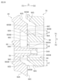
- FIG. 1 is a sectional view of a clutch device according to one embodiment.
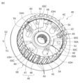
- FIG. 2 is a perspective view of a clutch center according to one embodiment.
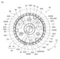
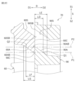
- FIG. 3 is a plan view of a clutch center according to one embodiment.
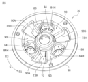
- FIG. 4 is a perspective view of a pressure plate according to one embodiment.
- FIG. 5 is a plan view of a pressure plate according to one embodiment.
- FIG. 6 is a perspective view of a pressure plate according to one embodiment.
- FIG. 7 is a plan view of a pressure plate according to one embodiment.
- FIG. 8 is a partially enlarged side view of the pressure side cam portion according to one embodiment.
- FIG. 9 is an enlarged perspective view of a portion of the pressure plate according to one embodiment.
- FIG. 1 is a sectional view of a clutch device according to one embodiment.
- FIG. 2 is a perspective view of a clutch center according to one embodiment.
- FIG. 3 is a plan view of a clutch center according to one embodiment.
- FIG. 4 is
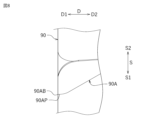
- FIG. 10 is a plan view showing a state in which the clutch center and pressure plate according to one embodiment are combined.
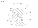
- FIG. 11A is a schematic diagram illustrating the actions of the center side assist cam surface and the pressure side assist cam surface.
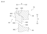
- FIG. 11B is a schematic diagram illustrating the actions of the center side slipper cam surface and the pressure side slipper cam surface.
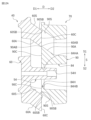
- FIG. 12A is a partially enlarged sectional view of a pressure plate and a clutch center according to one embodiment.
- FIG. 12B is an enlarged cross-sectional view of a part of the pressure plate and the clutch center when the pressure side top surface and the center side top surface are in contact with each other according to one embodiment.
- FIG. 12C is an enlarged cross-sectional view of a portion of FIG. 12B.
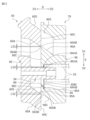
- FIG. 13 is a partially enlarged sectional view of a pressure plate and a clutch center according to another embodiment.
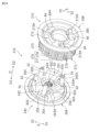
- FIG. 14 is an exploded perspective view of a clutch center and a pressure plate according to another embodiment.
- FIG. 15 is a perspective view of a pressure plate according to another embodiment.
- FIG. 1 is a sectional view of a clutch device 10 according to a first embodiment.
- the clutch device 10 is provided, for example, in a vehicle such as a motorcycle.
- the clutch device 10 is, for example, a device that transmits or interrupts rotational driving force of an input shaft (crankshaft) of an engine of a motorcycle to an output shaft 15.
- the clutch device 10 is a device for transmitting or interrupting the rotational driving force of the input shaft to the driving wheels (rear wheels) via the output shaft 15.
- Clutch device 10 is arranged between the engine and the transmission.
- direction D which is an example of a moving direction
- direction D the direction in which the pressure plate 70 approaches the clutch center 40
- direction D The direction in which the pressure plate 70 moves away from the clutch center 40
- the circumferential direction of the clutch center 40 and the pressure plate 70 is defined as a circumferential direction S
- the direction from one pressure side cam part 90 to the other pressure side cam part 90 with respect to the circumferential direction S is a first circumferential direction S1 (FIG.
- the direction from the other pressure side cam part 90 to one pressure side cam part 90 is defined as a second circumferential direction S2 (see FIG. 5).
- the axial direction of the output shaft 15, the axial direction of the clutch housing 30, the axial direction of the clutch center 40, and the axial direction of the pressure plate 70 are the same direction as the direction D.
- the pressure plate 70 and the clutch center 40 rotate in the first circumferential direction S1.
- the above-mentioned direction is merely a direction determined for convenience of explanation, and does not limit the installation mode of the clutch device 10 in any way, nor does it limit the present invention in any way.
- the clutch device 10 includes an output shaft 15, an input rotary plate 20, an output rotary plate 22, a clutch housing 30, a clutch center 40, a pressure plate 70, and a stopper plate 100. , is equipped with.
- the output shaft 15 is a shaft body formed in a hollow shape.
- One end of the output shaft 15 rotatably supports an input gear 35 and a clutch housing 30, which will be described later, via a needle bearing 15A.
- Output shaft 15 fixedly supports clutch center 40 via nut 15B. That is, the output shaft 15 rotates integrally with the clutch center 40.
- the other end of the output shaft 15 is connected to, for example, a transmission (not shown) of a two-wheeled automobile.
- the output shaft 15 includes a push rod 16A in its hollow portion 15H and a push member 16B provided adjacent to the push rod 16A.
- the hollow portion 15H has a function as a clutch oil flow path. Clutch oil flows within the output shaft 15, that is, within the hollow portion 15H.
- the push rod 16A and the push member 16B are provided to be slidable within the hollow portion 15H of the output shaft 15.
- the push rod 16A has one end (the end on the left side in the figure) connected to a clutch operating lever (not shown) of the motorcycle, and is pushed by sliding in the hollow portion 15H when the clutch operating lever is operated.
- the member 16B is pressed in the second direction D2.
- a portion of the push member 16B protrudes outward from the output shaft 15 (here, in the second direction D2), and is connected to the release bearing 18 provided on the pressure plate 70.
- the push rod 16A and the push member 16B are formed to be thinner than the inner diameter of the hollow portion 15H, and the circulation of clutch oil is ensured within the hollow portion 15H.
- the clutch housing 30 is made of aluminum alloy.
- the clutch housing 30 is formed into a cylindrical shape with a bottom. As shown in FIG. 1, the clutch housing 30 includes a bottom wall 31 formed in a substantially circular shape and a side wall 33 extending from an edge of the bottom wall 31 in a second direction D2.
- the clutch housing 30 holds a plurality of input-side rotating plates 20.
- an input gear 35 is provided on the bottom wall 31 of the clutch housing 30.
- the input gear 35 is fixed to the bottom wall 31 by a rivet 35B via a torque damper 35A.
- the input gear 35 meshes with a drive gear (not shown) that is rotated by rotation of the input shaft of the engine.
- the input gear 35 is rotated independently from the output shaft 15 and integrally with the clutch housing 30.
- the input side rotary plate 20 is rotationally driven by the rotational drive of the input shaft. As shown in FIG. 1, the input rotary plate 20 is held on the inner peripheral surface of the side wall 33 of the clutch housing 30. As shown in FIG. The input rotary plate 20 is held in the clutch housing 30 by spline fitting. The input side rotating plate 20 is provided so as to be displaceable along the axial direction of the clutch housing 30. The input side rotary plate 20 is provided so as to be rotatable integrally with the clutch housing 30.
- the input side rotating plate 20 is a member that is pressed against the output side rotating plate 22.
- the input side rotary plate 20 is a flat plate formed in an annular shape.
- the input rotary plate 20 is formed by punching a thin plate made of SPCC (cold rolled steel plate) into an annular shape. Friction materials (not shown) made of a plurality of pieces of paper are attached to the front and back surfaces of the input-side rotary plate 20. Grooves with a depth of several ⁇ m to several tens of ⁇ m are formed between the friction materials to hold clutch oil.
- the clutch center 40 is housed in the clutch housing 30.
- the clutch center 40 is arranged concentrically with the clutch housing 30.
- Clutch center 40 is made of aluminum alloy.
- the clutch center 40 has a cylindrical main body 42 and a flange 68 extending radially outward from the outer peripheral edge of the main body 42.
- the clutch center 40 holds at least a portion of the input side rotary plates 20 and a plurality of output side rotary plates 22 arranged alternately in the direction D.
- the clutch center 40 is rotationally driven together with the output shaft 15.
- the main body 42 includes an annular base wall 43, an outer circumferential wall 45 located radially outside the base wall 43 and extending in the second direction D2, and a peripheral wall 45 located at the center of the base wall 43.
- the output shaft holding portion 50 is provided, a plurality of center side cam portions 60 connected to the base wall 43 and the outer peripheral wall 45, and a center side fitting portion 58 are provided.
- the output shaft holding portion 50 is formed in a cylindrical shape.
- the output shaft holder 50 has an insertion hole 51 into which the output shaft 15 is inserted and spline-fitted.
- the insertion hole 51 is formed to penetrate the base wall 43.
- a plurality of spline grooves are formed along the axial direction in the inner circumferential surface 50A of the output shaft holding portion 50 that forms the insertion hole 51.
- the output shaft 15 is connected to the output shaft holder 50 .
- the outer peripheral wall 45 of the clutch center 40 is arranged radially outward from the output shaft holding part 50.
- a spline fitting portion 46 is provided on the outer peripheral surface of the outer peripheral wall 45 .
- the spline fitting portion 46 is formed between a plurality of center side fitting teeth 47 extending in the axial direction of the clutch center 40 along the outer circumferential surface of the outer peripheral wall 45 and adjacent center side fitting teeth 47, and is formed between adjacent center side fitting teeth 47.
- 40, a plurality of spline grooves 48 extending in the axial direction, and an oil discharge hole 49.
- the center side fitting tooth 47 holds the output side rotating plate 22.
- the plurality of center-side fitting teeth 47 are arranged in the circumferential direction S.
- the plurality of center side fitting teeth 47 are formed at equal intervals in the circumferential direction S.
- the plurality of center side fitting teeth 47 are formed in the same shape.
- the center side fitting teeth 47 protrude radially outward from the outer circumferential surface of the outer circumferential wall 45 .
- the oil discharge hole 49 is formed to penetrate the outer peripheral wall 45 in the radial direction.
- the oil discharge hole 49 is formed between adjacent center side fitting teeth 47 . That is, the oil discharge hole 49 is formed in the spline groove 48.
- the oil discharge hole 49 is formed on the side of the center side cam portion 60.
- the oil discharge hole 49 is formed on the side of the center side slipper cam surface 60S of the center side cam portion 60.
- the oil discharge hole 49 is formed closer to the second circumferential direction S2 than the center side slipper cam surface 60S.
- the oil discharge hole 49 is formed closer to the first circumferential direction S1 than a boss portion 54, which will be described later.
- three oil discharge holes 49 are formed at three locations in the circumferential direction S of the outer peripheral wall 45.
- the oil discharge holes 49 are arranged at equal intervals in the circumferential direction S.
- the oil discharge hole 49 communicates the inside and outside of the clutch center 40.
- the oil discharge hole 49 is a hole for discharging clutch oil that has flowed into the clutch center 40 from the output shaft 15 to the outside of the clutch center 40 .
- the output rotary plate 22 is held by the spline fitting portion 46 of the clutch center 40 and the pressure plate 70. A portion of the output rotary plate 22 is held in center-side fitting teeth 47 and a spline groove 48 of the clutch center 40 by spline fitting. The other part of the output side rotary plate 22 is held by pressure side fitting teeth 77 (see FIG. 4), which will be described later, of the pressure plate 70.
- the output side rotary plate 22 is provided so as to be displaceable along the axial direction of the clutch center 40 .
- the output side rotating plate 22 is provided to be rotatable integrally with the clutch center 40.
- the output side rotating plate 22 is a member that is pressed against the input side rotating plate 20.
- the output side rotating plate 22 is a flat plate formed in an annular shape.
- the output side rotating plate 22 is formed by punching out a thin plate material made of SPCC material into an annular shape. Grooves with a depth of several ⁇ m to several tens of ⁇ m are formed on the front and back surfaces of the output rotary plate 22 to hold clutch oil.
- the front and back surfaces of the output rotary plate 22 are subjected to surface hardening treatment to improve wear resistance. Note that the friction material provided on the input side rotary plate 20 may be provided on the output side rotary plate 22 instead of the input side rotary plate 20, or on each of the input side rotary plate 20 and the output side rotary plate 22. may be provided.
- the center side cam portion 60 is configured to quickly increase the assist torque, which is a force that increases the pressing force (pressing force) between the input side rotary plate 20 and the output side rotary plate 22, or the input side rotary plate 20 and the output side rotary plate 22. It is formed into a table-like shape with a cam surface consisting of an inclined surface forming an Assist & Slipper (registered trademark) mechanism that generates a slipper torque that is a force for separating the clutch and shifting the clutch to a half-clutch state.
- the center side cam portion 60 is formed to protrude from the base wall 43 in the second direction D2. As shown in FIG. 3, the center-side cam parts 60 are arranged at equal intervals in the circumferential direction S of the clutch center 40. In this embodiment, the clutch center 40 has three center-side cam parts 60, but the number of center-side cam parts 60 is not limited to three.
- the center-side cam portion 60 is located radially outward from the output shaft holding portion 50.
- the center side cam portion 60 has a center side assist cam surface 60A, a center side slipper cam surface 60S, and a center side top surface 60C.
- the center side assist cam surface 60A moves the pressure plate 70 toward the clutch center in order to increase the pressing force (pressing force) between the input side rotary plate 20 and the output side rotary plate 22 when the center side assist cam surface 60A rotates relative to the pressure plate 70. 40.
- the position of the pressure plate 70 relative to the clutch center 40 does not change, and there is no need for the pressure plate 70 to physically approach the clutch center 40.
- the pressure plate 70 may be physically displaced with respect to the clutch center 40.
- the center side slipper cam surface 60S moves the pressure plate 70 toward the clutch center 40 in order to reduce the pressing force (pressing force) between the input side rotary plate 20 and the output side rotary plate 22 when the center side slipper cam surface 60S rotates relative to the pressure plate 70. It is configured to be separated from the In the center side cam parts 60 that are adjacent to each other in the circumferential direction S, the center side assist cam surface 60A of one center side cam part 60L and the center side slipper cam surface 60S of the other center side cam part 60M are opposed to each other in the circumferential direction S. It is located.
- the center side top surface 60C is located between the center side assist cam surface 60A and the center side slipper cam surface 60S. More specifically, the center side top surface 60C is located between the center side assist cam surface 60A and the center side slipper cam surface 60S in the circumferential direction S. The center side top surface 60C is continuous with the center side assist cam surface 60A and the center side slipper cam surface 60S.
- the connecting portion between the center side top surface 60C and the center side assist cam surface 60A and the connecting portion between the center side top surface 60C and the center side slipper cam surface 60S are curved surfaces.
- the clutch center 40 includes a plurality (three in this embodiment) of boss portions 54.
- the boss portion 54 is a member that supports the pressure plate 70.
- the plurality of boss portions 54 are arranged at equal intervals in the circumferential direction S.
- the boss portion 54 is formed in a cylindrical shape.
- the boss portion 54 is located radially outward from the output shaft holding portion 50.
- the boss portion 54 extends toward the pressure plate 70 (that is, toward the second direction D2).
- the boss portion 54 is provided on the base wall 43.
- the boss portion 54 is formed with a screw hole 54H into which the bolt 28 (see FIG. 1) is inserted.
- the screw hole 54H extends in the axial direction of the clutch center 40.
- the screw hole 54H is a hole for attaching the stopper plate 100.
- the center side fitting part 58 is located radially outward from the output shaft holding part 50.
- the center side fitting portion 58 is located radially outward from the center side cam portion 60.
- the center-side fitting portion 58 is located closer to the second direction D2 than the center-side cam portion 60.
- the center side fitting portion 58 is formed on the inner circumferential surface of the outer circumferential wall 45 .
- the center side fitting part 58 is configured to be slidably fitted onto a pressure side fitting part 88 (see FIG. 4), which will be described later.
- the inner diameter of the center side fitting part 58 is formed to have a fitting tolerance that allows the flow of clutch oil flowing out from the tip 15T of the output shaft 15 to the pressure side fitting part 88.
- the center side fitting part 58 is formed to have an inner diameter larger than the outer diameter of the pressure side fitting part 88 by 0.1 mm.
- the dimensional tolerance between the inner diameter of the center side fitting part 58 and the outer diameter of the pressure side fitting part 88 is set appropriately depending on the amount of clutch oil to be circulated, and is, for example, 0.1 mm or more and 0.5 mm. It is as follows.
- the clutch center 40 has a center-side cam hole 43H that passes through a portion of the base wall 43.
- the center side cam hole 43H extends from the side of the output shaft holding portion 50 to the outer peripheral wall 45.
- the center side cam hole 43H is formed between the center side assist cam surface 60A of the center side cam portion 60 and the boss portion 54.
- the center-side assist cam surface 60A and a portion of the center-side cam hole 43H overlap.
- the pressure plate 70 is provided so that it can approach or move away from the clutch center 40 and can rotate relative to it.
- the pressure plate 70 is configured to be able to press the input side rotary plate 20 and the output side rotary plate 22.
- Pressure plate 70 is arranged concentrically with clutch center 40 and clutch housing 30.
- Pressure plate 70 is made of aluminum alloy.
- the pressure plate 70 includes a main body 72 and a flange 98 connected to the outer peripheral edge of the main body 72 on the second direction D2 side and extending radially outward.
- the main body 72 protrudes beyond the flange 98 in the first direction D1.
- the pressure plate 70 holds at least a portion of the plurality of output side rotary plates 22 arranged alternately with the input side rotary plates 20 .
- the main body 72 includes a cylindrical portion 80, a plurality of pressure side cam portions 90, a pressure side fitting portion 88, and a spring housing portion 84 (see also FIG. 6).
- the cylindrical portion 80 is formed in a cylindrical shape.
- the cylindrical portion 80 is integrally formed with the pressure side cam portion 90.
- the cylindrical portion 80 accommodates the tip portion 15T (see FIG. 1) of the output shaft 15.
- the release bearing 18 (see FIG. 1) is accommodated in the cylindrical portion 80.
- the cylindrical portion 80 is a portion that receives the pressing force from the push member 16B.
- the cylindrical portion 80 is a portion that receives clutch oil flowing out from the tip portion 15T of the output shaft 15.
- the pressure side cam portion 90 is formed into a table-like shape having a cam surface consisting of an inclined surface that constitutes an assist & slipper (registered trademark) mechanism that slides on the center side cam portion 60 to generate assist torque or slipper torque. has been done.
- the pressure side cam portion 90 is formed to protrude further than the flange 98 in the first direction D1.
- the pressure side cam parts 90 are arranged at equal intervals in the circumferential direction S of the pressure plate 70.
- the pressure plate 70 has three pressure side cam parts 90, but the number of pressure side cam parts 90 is not limited to three.
- the pressure side cam portion 90 is located radially outward from the cylindrical portion 80.
- the pressure side cam portion 90 has a pressure side assist cam surface 90A (see also FIGS. 7 and 9), a pressure side slipper cam surface 90S, and a pressure side top surface 90C.
- the pressure side assist cam surface 90A is configured to be able to come into contact with the center side assist cam surface 60A.
- the pressure side assist cam surface 90A moves the pressure plate 70 toward the clutch center in order to increase the pressing force (pressing force) between the input side rotary plate 20 and the output side rotary plate 22 when the pressure side assist cam surface 90A rotates relative to the clutch center 40. 40.
- the pressure side slipper cam surface 90S is configured to be able to come into contact with the center side slipper cam surface 60S.
- the pressure side slipper cam surface 90S moves the pressure plate 70 toward the clutch center 40 in order to reduce the pressing force (pressing force) between the input side rotary plate 20 and the output side rotary plate 22 when the pressure side slipper cam surface 90S rotates relative to the clutch center 40. It is configured to be separated from the In the pressure side cam parts 90 that are adjacent in the circumferential direction S, the pressure side assist cam surface 90A of one pressure side cam part 90L and the pressure side slipper cam surface 90S of the other pressure side cam part 90M are opposed in the circumferential direction S. It is located.
- the pressure side top surface 90C is located between the pressure side assist cam surface 90A and the pressure side slipper cam surface 90S. More specifically, the pressure side top surface 90C is located between the pressure side assist cam surface 90A and the pressure side slipper cam surface 90S in the circumferential direction S. The pressure side top surface 90C is continuous with the pressure side assist cam surface 90A and the pressure side slipper cam surface 90S.
- the connection portion between the pressure side top surface 90C and the pressure side assist cam surface 90A and the connection portion between the pressure side top surface 90C and the pressure side slipper cam surface 90S are curved surfaces.
- the pressure side assist cam surface 90A, the pressure side slipper cam surface 90S, the center side assist cam surface 60A, and the center side slipper cam surface 60S are parallel to each other.
- a linearly chamfered chamfered portion 90AP is formed at the end of the pressure-side assist cam surface 90A of the pressure-side cam portion 90 in the circumferential direction S.
- the corner of the chamfered portion 90AP (the corner on the first direction D1 and first circumferential direction S1 side) is a right angle. More specifically, the chamfered portion 90AP is formed at the end 90AB of the pressure side assist cam surface 90A in the first circumferential direction S1.
- the pressure side fitting portion 88 is located radially outward from the pressure side cam portion 90.
- the pressure side fitting portion 88 is located closer to the second direction D2 than the pressure side cam portion 90.
- the pressure side fitting part 88 is configured to be slidably fitted into the center side fitting part 58 (see FIG. 2).
- the pressure plate 70 has a pressure side cam hole 73H that passes through the main body 72 and a part of the flange 98.
- the pressure side cam hole 73H is located radially outward from the cylindrical portion 80.
- the pressure side cam hole 73H extends from the side of the cylindrical portion 80 to the radially outer side of the pressure side fitting portion 88.
- the pressure side cam hole 73H is formed between the pressure side assist cam surface 90A and the pressure side slipper cam surface 90S of the adjacent pressure side cam portions 90. As shown in FIGS. 5 and 7, when viewed from the axial direction of the pressure plate 70, the pressure side assist cam surface 90A and a portion of the pressure side cam hole 73H overlap.
- the pressure plate 70 includes a plurality of pressure side fitting teeth 77 arranged on the flange 98.
- the pressure side fitting teeth 77 hold the output side rotating plate 22.
- the pressure side fitting teeth 77 protrude from the flange 98 in the first direction D1.
- the pressure side fitting teeth 77 are located radially outward from the cylindrical portion 80. It is located radially outward from the pressure side cam portion 90.
- the pressure side fitting teeth 77 are located radially outward from the pressure side cam portion 90.
- the pressure side fitting teeth 77 are located radially outward from the pressure side fitting portion 88.
- the plurality of pressure side fitting teeth 77 are arranged in the circumferential direction S.
- the plurality of pressure side fitting teeth 77 are arranged at equal intervals in the circumferential direction S. Note that in this embodiment, some of the pressure-side fitting teeth 77 are removed, so the interval between these parts is widened, but other adjacent pressure-side fitting teeth 77 are arranged at equal intervals. There is.
- the spring housing portion 84 is formed in the pressure side cam portion 90.
- the spring housing portion 84 is formed to be recessed from the second direction D2 to the first direction D1.
- the spring housing portion 84 is formed in an elliptical shape.
- the spring accommodating portion 84 accommodates the pressure spring 25 (see FIG. 1).
- An insertion hole 84H into which the boss portion 54 (see FIG. 2) is inserted is formed through the spring housing portion 84. That is, the insertion hole 84H is formed through the pressure side cam portion 90.
- the insertion hole 84H is formed in an elliptical shape.
- the insertion hole 84H is located closer to the second circumferential direction S2 than the pressure side assist cam surface 90A.
- the insertion hole 84H is located closer to the first circumferential direction S1 than the pressure side slipper cam surface 90S.
- the pressure spring 25 is housed in the spring housing portion 84.
- the pressure spring 25 is externally fitted onto the boss portion 54 inserted into the insertion hole 84H of the spring housing portion 84.
- the pressure spring 25 urges the pressure plate 70 toward the clutch center 40 (that is, toward the first direction D1).
- the pressure spring 25 is, for example, a coil spring made of spirally wound spring steel.
- FIG. 10 is a plan view showing a state in which the clutch center 40 and pressure plate 70 are combined.
- the pressure side assist cam surface 90A and the center side assist cam surface 60A are not in contact with each other, and the pressure side slipper cam surface 90S and the center side slipper cam surface 60S are not in contact with each other.
- the pressure plate 70 is closest to the clutch center 40.
- the distance L5 in the circumferential direction S between the boss portion 54 and the end portion 84HA of the insertion hole 84H on the pressure side assist cam surface 90A side is It is longer than the distance L6 in the circumferential direction S from the end 84HB of the hole 84H on the pressure side slipper cam surface 90S side (that is, on the second circumferential direction S2 side).
- the pressure side slipper cam surface 90S does not contact the center side slipper cam surface 60S
- the pressure side assist cam surface 90A does not contact the center side assist cam surface 60A.
- distance L5 is longer than distance L6.
- the entire range in the circumferential direction S from the position immediately before the pressure side slipper cam surface 90S and the center side slipper cam surface 60S contact to the position immediately before the pressure side assist cam surface 90A and the center side assist cam surface 60A contact. is the pressure side slipper cam from the range in the circumferential direction S from the position where the pressure side slipper cam surface 90S and the center side slipper cam surface 60S contact to the position where the pressure side assist cam surface 90A and the center side assist cam surface 60A contact.
- This range excludes the position where the surface 90S and the center-side slipper cam surface 60S contact and the position where the pressure-side assist cam surface 90A and the center-side assist cam surface 60A contact.
- FIG. 12A is a partially enlarged cross-sectional view of the pressure plate 70 and the clutch center 40.
- FIG. 12A is a cross-sectional view taken along the line XIIA-XIIA in FIG. 10. That is, FIG. 12A is a cross-sectional view taken along a plane passing through the axis 54C of the boss portion 54 and extending in the circumferential direction S and in the axial direction of the output shaft 15.
- the center side top surface 60C and the pressure side top surface 90C are located at the same position with respect to the direction D, and the end 60AB of the center side assist cam surface 60A in the second circumferential direction S2 is the pressure side assist cam surface 60C.
- the end 90SB of the pressure side slipper cam surface 90S in the first circumferential direction S1 faces the second circumferential direction S2 of the center side slipper cam surface 60S. It is located on the first circumferential direction S1 side with respect to the end portion 60SB. In the circumferential direction S, a gap is formed between the end portion 60SB and the end portion 90SB.
- the center side assist An end 60AB of the cam surface 60A in the second circumferential direction S2 is located closer to the first circumferential direction S1 than an end 90AB of the pressure-side assist cam surface 90A in the first circumferential direction S1.
- a gap is formed between the end portion 60AB and the end portion 90AB.
- center side top surface 60C and the pressure side top surface 90C are located at the same position in the circumferential direction S, the center side top surface 60C and the pressure side top surface 90C are located at the same position in the direction D. This means the position where the surface 60C and the pressure side top surface 90C are in contact.
- the boss portion 54 is inserted into the insertion hole 84H, and the center side top surface 60C and the pressure side top surface 90C are brought into contact in the direction D ( (for example, surface contact).
- the pressure side top surface 90C and the center side top surface 60C are located at the same position with respect to the direction D, and the end 84HB and the boss on the second circumferential direction S2 side (that is, the pressure side slipper cam surface 90S side) of the insertion hole 84H 54, the end 90AB of the pressure side assist cam surface 90A in the first circumferential direction S1 is smaller than the end 60AB of the center side assist cam surface 60A in the second circumferential direction S2.
- the first end 90SB of the pressure side slipper cam surface 90S in the circumferential direction S1 is located on the circumferential direction S1 side, and the first end 90SB of the pressure side slipper cam surface 90S is closer to the first circumferential direction than the second end 60SB of the center side slipper cam surface 60S in the circumferential direction S2. It is located on the direction S1 side.
- the pressure side top surface 90C and the center side top surface 60C are located at the same position with respect to the direction D, and the second circumferential direction S2 side of the insertion hole 84H (that is, the pressure side slipper cam surface 90S side) and the boss portion 54, from the end 90AB of the pressure side assist cam surface 90A in the first circumferential direction S1 to the end 90AB of the center side assist cam surface 60A in the second circumferential direction S2.
- the length in the circumferential direction S to the end 60AB is LA, and the length in the circumferential direction S from the end 84HA of the insertion hole 84H on the first circumferential direction S1 side (that is, the pressure side assist cam surface 90A side) to the boss portion 54
- LB is the length
- LC is the length in the circumferential direction S from the end 90SB of the pressure side slipper cam surface 90S in the first circumferential direction S1 to the end 60SB of the center side slipper cam surface 60S in the second circumferential direction S2.
- the pressure plate 70 can be assembled to the clutch center 40 without interfering with the center-side slipper cam surface 60S.
- the pressure side top surface 90C and the center side top surface 60C are located at the same position with respect to the direction D, and the second circumferential direction S2 side of the insertion hole 84H (that is, the pressure side slipper cam surface 90S side) and the boss portion 54, a straight line P1 parallel to the direction D and passing through the end 60AB in the second circumferential direction S2 of the center side assist cam surface 60A and the pressure side assist cam surface 90A intersects Q1 to the pressure side top surface 90C is LD, and the length of the pressure side assist cam surface 90A in direction D is LE, then LD ⁇ LE/4 (preferably LD A point where the center side assist cam surface 60A intersects a straight line P2 that satisfies the formula ⁇ LE/2) and is parallel to the direction D and passes through the end 90AB of the pressure side assist cam surface 90A in the first circumferential direction S1.
- LD ⁇ LE/4 preferably LD A point where the center side assist cam surface 60A intersects a straight line P2 that satis
- the stopper plate 100 is provided so as to be able to come into contact with the pressure plate 70.
- the stopper plate 100 is a member that prevents the pressure plate 70 from being separated from the clutch center 40 by a predetermined distance or more in the second direction D2.
- the stopper plate 100 is fixed to the boss portion 54 of the clutch center 40 with bolts 28.
- the pressure plate 70 is fixed by tightening bolts 28 to the boss portion 54 via the stopper plate 100 with the boss portion 54 of the clutch center 40 and the pressure spring 25 disposed in the spring housing portion 84 .
- the bolt 28 is inserted into the screw hole 54H of the boss portion 54.
- the stopper plate 100 is formed into a substantially triangular shape when viewed from above.
- the pressure side slipper cam surface 90S and the center side slipper cam surface 60S are respectively 50% or more and 90% or less of the area of the pressure side slipper cam surface 90S, and the center side More than 50% and less than 90% of the area of the slipper cam surface 60S is in contact with each other.
- the pressure spring 25 is separated from the side wall of the spring housing portion 84. That is, the pressure spring 25 is not sandwiched between the boss portion 54 and the spring housing portion 84, and application of excessive stress to the boss portion 54 is suppressed.
- Length L1 in the circumferential direction S from 90AB to the end 90SB in the first circumferential direction S1 of the pressure side slipper cam surface 90S located on the second circumferential direction S2 side of the other pressure side cam portion 90M is the length in the circumferential direction from the end 60AB of the center side assist cam surface 60A of one center side cam portion 60 in the second circumferential direction S2 to the end 60SB of the center side slipper cam surface 60S in the second circumferential direction S2.
- length L2 (see Figure 3).
- the center of the pressure plate 70 (here, the center 80C of the cylindrical portion 80) and one pressure side cam portion 90L of the pressure side cam portions 90 adjacent in the circumferential direction S
- the angle ⁇ 1 (see FIG. 5) between the slipper cam surface 90S and the end 90SB in the first circumferential direction S1 is between the center 50C of the output shaft holding portion 50 and the center side assist cam surface 60A of one center side cam portion 60.
- the angle ⁇ 1 is an angle between a straight line passing through the center 80C and the end 90AB of the cylindrical portion 80 and a straight line passing through the center 80C and the end 90SB.
- the angle ⁇ 2 is an angle between a straight line passing through the center 50C and the end 60AB of the output shaft holding part 50 and a straight line passing through the center 50C and the end 60SB.
- the length L3 in the circumferential direction S from the end 60AB of the center side assist cam surface 60A in the second circumferential direction S2 to the boss portion 54 is the length L3 (see FIG. 3) of the first circumferential direction of the pressure side assist cam surface 90A. It is longer than the length L4 in the circumferential direction S from the end portion 90AB in the direction S1 to the insertion hole 84H (see FIG. 5).
- the angle ⁇ 3 is an angle between a straight line passing through the center 50C and the end 60AB of the output shaft holding portion 50 and a straight line passing through the center 50C and the axis 54C of the boss portion 54.
- the angle ⁇ 4 is an angle between a straight line passing through the center 80C of the cylindrical portion 80 and the end portion 90AB, and a straight line passing through the center 80C and the center 84HC of the insertion hole 84H.
- a predetermined amount of clutch oil is filled in the clutch device 10.
- the clutch oil flows into the clutch center 40 and pressure plate 70 through the hollow part 15H of the output shaft 15, and then flows through the gap between the center side fitting part 58 and the pressure side fitting part 88 and the oil discharge hole 49. and is supplied to the input side rotary plate 20 and the output side rotary plate 22.
- Clutch oil absorbs heat and prevents friction material from wearing out.
- the clutch device 10 of this embodiment is a so-called wet multi-disc friction clutch device.
- the clutch device 10 is arranged between the engine and the transmission of the motorcycle, and transmits the rotational driving force of the engine to the transmission when the driver operates the clutch operation lever. and cut off.
- the clutch release mechanism (not shown) does not press the push rod 16A. force) to press the input side rotary plate 20.
- the clutch center 40 is rotated in a clutch ON state in which the input side rotary plate 20 and the output side rotary plate 22 are pressed against each other and frictionally connected. That is, the rotational driving force of the engine is transmitted to the clutch center 40, and the output shaft 15 is rotationally driven.
- the clutch release mechanism presses the push rod 16A, so that the pressure plate 70 acts as a pressure spring. 25 and is displaced in the direction away from the clutch center 40 (second direction D2).
- the clutch center 40 enters a clutch OFF state in which the frictional connection between the input-side rotary plate 20 and the output-side rotary plate 22 is eliminated, so that the rotational drive is attenuated or the rotational drive is stopped. That is, the rotational driving force of the engine is cut off to the clutch center 40.
- the clutch oil flowing in the hollow portion H of the output shaft 15 and flowing out from the tip 15T of the output shaft 15 is guided into the clutch center 40 as in the clutch ON state.
- the pressure plate 70 is separated from the clutch center 40, the amount of engagement with the center side fitting portion 58 and the pressure side fitting portion 88 decreases.
- the clutch oil in the cylindrical portion 80 more actively flows out of the clutch center 40 and flows to various locations inside the clutch device 10.
- the clutch oil can be actively guided between the input side rotary plate 20 and the output side rotary plate 22 which are separated from each other.
- the pressure side top surface 90C and the center side top surface 60C are located at the same position with respect to the direction D, and the second circumferential direction S2 side of the insertion hole 84H
- the end 90AB of the pressure side assist cam surface 90A in the first circumferential direction S1 is the end of the center side assist cam surface 60A in the second circumferential direction S2.
- the end 90SB of the pressure side slipper cam surface 90S in the first circumferential direction S1 which is located on the first circumferential direction S1 side from 60AB, is the end 60SB of the center side slipper cam surface 60S in the second circumferential direction S2.
- the pressure side top surface 90C and the center side top surface 60C first come into contact with. That is, since the pressure side slipper cam surface 90S and the center side slipper cam surface 60S do not contact each other initially, the center side slipper cam surface 60S is prevented from being damaged by the end 90SB of the pressure side slipper cam surface 90S in the first circumferential direction S1. be able to.
- the pressure side top surface 90C and the center side top surface 60C are located at the same position with respect to the direction D, and the end 84HB of the insertion hole 84H on the second circumferential direction S2 side is in contact with the boss portion 54.
- the formulas LB>LA and LC>LA are satisfied.
- the pressure plate 70 can be assembled to the clutch center 40 by rotating the pressure plate 70 in the second circumferential direction S2.
- the pressure side top surface 90C and the center side top surface 60C are located at the same position with respect to the direction D, and the end 84HB of the insertion hole 84H on the second circumferential direction S2 side is in contact with the boss portion 54.
- the expression LD ⁇ LE/4 is satisfied, and the expression LF ⁇ LG/4 is satisfied.
- the pressure side top surface 90C and the center side top surface 60C come into contact, if there is little overlap between the pressure side top surface 90C and the center side top surface 60C in the circumferential direction S, the pressure side assist cam surface 90A and the center side top surface 90C may There is a possibility that the side assist cam surface 60A may be damaged.
- a sufficient overlapping portion between the pressure side top surface 90C and the center side top surface 60C is secured, and the pressure side assist cam Damage to the surface 90A and the center side assist cam surface 60A can be suppressed.
- LD, LE, LF, and LG satisfy the formulas LD ⁇ LE/2 and LF ⁇ LG/2. According to the above aspect, a sufficient overlapping portion between the pressure side top surface 90C and the center side top surface 60C is ensured, and damage to the pressure side assist cam surface 90A and the center side assist cam surface 60A can be suppressed.
- the pressure side top surface 90C is higher than the center side top surface 60C. It is located on the first direction D1 side. In this way, the clutch center 40 and pressure plate 70 of this embodiment can be reliably assembled.
- FIG. 13 is a partially enlarged sectional view of the pressure plate 70 and the clutch center 40 according to the second embodiment.
- FIG. 13 corresponds to a cross-sectional view taken along a plane passing through the axis 54C of the boss portion 54 and extending in the circumferential direction S and in the axial direction of the output shaft 15.
- the pressure plate 70 includes a ring-shaped spring seat 85 accommodated in a spring accommodating portion 84.
- the ring shape includes, for example, an O shape (O ring) and a C shape (C ring).
- the spring seat 85 is formed into an elliptical shape.
- the spring seat 85 is arranged so as to be movable in the circumferential direction S within the spring housing portion 84 .
- the spring seat 85 is located closest to the second circumferential direction S2 in the spring housing portion 84. That is, the end portion 85A of the spring seat 85 in the second circumferential direction S2 contacts the inner wall 84A of the spring housing portion 84.
- the boss portion 54 penetrates the spring seat 85.
- the pressure spring 25 is arranged on the surface 85M of the spring seat 85 on the second direction D2 side.
- the total length of the first length LS1 and the second length LS2 is 3 Length longer than LS3. That is, (LS1+LS2)>LS3 holds true.
- the first length LS1 is the circumferential direction S between the end 60AB of the center side assist cam surface 60A in the second circumferential direction S2 and the end 90AB of the pressure side assist cam surface 90A in the first circumferential direction S1. is the distance.
- the second length LS2 is the distance in the circumferential direction S between the end 60SB of the center side slipper cam surface 60S in the second circumferential direction S2 and the end 90SB of the pressure side slipper cam surface 90S in the first circumferential direction S1.
- the third length LS3 is such that the spring seat 85 is located closest to the second circumferential direction S2 side in the spring housing portion 84, and the first inner edge 85HA, which is the inner edge of the spring seat 85 on the first circumferential direction S1 side, is at the boss portion.
- End portion 84HA is an example of a first inner edge.
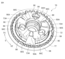
- FIG. 14 is an exploded perspective view of the clutch center 240 and pressure plate 270 of the clutch device 210 according to the third embodiment.
- the clutch center 240 is housed in the clutch housing 30 (see FIG. 1). Clutch center 240 is arranged concentrically with clutch housing 30. As shown in FIG. 14, the clutch center 240 includes a main body 242 and a flange 268 connected to the outer peripheral edge of the main body 242 on the first direction D1 side and extending radially outward. The main body 242 protrudes further than the flange 268 in the second direction D2. Clutch center 240 does not hold output side rotating plate 22. The clutch center 240 is rotationally driven together with the output shaft 15 (see FIG. 1).
- the main body 242 includes an output shaft holding portion 250, a plurality of center side cam portions 60, and a center side fitting portion 258.
- the center side cam portion 60 is formed to protrude further in the second direction D2 than the flange 268.
- the center side cam portion 60 is located on the radially outer side of the output shaft holding portion 250.
- the output shaft holding portion 250 is formed in a cylindrical shape.
- the output shaft holder 250 has an insertion hole 251 into which the output shaft 15 (see FIG. 1) is inserted and spline-fitted.
- the insertion hole 251 is formed to penetrate the main body 242.
- a plurality of spline grooves are formed in the inner peripheral surface 250A of the output shaft holding portion 250 that forms the insertion hole 251 along the axial direction.
- the output shaft 15 is connected to the output shaft holder 250 .
- the clutch center 240 includes a plurality of (three in this embodiment) boss portions 54.
- the boss portion 54 is located radially outward from the output shaft holding portion 250.
- the boss portion 54 is provided on the main body 242.
- the clutch center 240 has a center-side cam hole 243H that passes through the main body 242 and a portion of the flange 268.
- the center side cam hole 243H passes through the main body 242 and the flange 268 in the direction D.
- the center side cam hole 243H extends from the side of the output shaft holding portion 250 to the flange 268.
- the center side cam hole 243H is formed between the center side assist cam surface 60A of the center side cam portion 60 and the boss portion 54. When viewed from the axial direction of clutch center 240, center-side assist cam surface 60A and a portion of center-side cam hole 243H overlap.
- the center side fitting portion 258 is provided on the main body 242.
- the center-side fitting portion 258 is located radially outward from the center-side cam portion 60.
- the center side fitting portion 258 is located closer to the first direction D1 than the center side cam portion 60.
- the center side fitting part 258 is configured to be slidably fitted into the pressure side fitting part 288 (see FIG. 15).
- the pressure plate 270 is provided so that it can approach or separate from the clutch center 240 and can rotate relative to it.
- the pressure plate 270 is configured to be able to press the input side rotary plate 20 and the output side rotary plate 22.
- Pressure plate 270 is arranged concentrically with clutch center 240 and clutch housing 30.
- the pressure plate 270 has a cylindrical main body 272 and a flange 298 extending radially outward from the outer peripheral edge of the main body 272.
- the pressure plate 270 holds the input side rotary plate 20 and a plurality of output side rotary plates 22 arranged alternately in the direction D. In this embodiment, the pressure plate 270 holds all the output side rotating plates 22.
- the main body 272 includes an annular base wall 273, an outer peripheral wall 275 located on the radially outer side of the base wall 273 and extending in the first direction D1, and a peripheral wall 275 provided at the center of the base wall 273. a cylindrical part 280, a plurality of pressure side cam parts 90 connected to the base wall 273 and the outer peripheral wall 275, a pressure side fitting part 288, and a spring housing part 84 (see FIG. 14). .
- the pressure side cam portion 90 is formed to protrude from the main body 272 in the first direction D1.
- the pressure side cam portion 90 is located on the radially outer side of the cylindrical portion 280.
- the pressure side cam portion 90 is located radially inner than the outer peripheral wall 275.
- the cylindrical portion 280 is formed in a cylindrical shape.
- the cylindrical portion 280 is formed integrally with the pressure side cam portion 90.
- the cylindrical portion 280 accommodates the tip portion 15T (see FIG. 1) of the output shaft 15.
- the release bearing 18 (see FIG. 1) is housed in the cylindrical portion 280.
- the cylindrical portion 280 is a portion that receives the pressing force from the push member 16B.
- the cylindrical portion 280 is a portion that receives clutch oil flowing out from the tip portion 15T of the output shaft 15.
- the outer peripheral wall 275 of the pressure plate 270 is arranged radially outward from the cylindrical portion 280.
- the outer peripheral wall 275 is formed in an annular shape extending in the direction D.
- a spline fitting portion 276 is provided on the outer circumferential surface 275A of the outer circumferential wall 275.
- the spline fitting portion 276 is formed between a plurality of pressure side fitting teeth 277 extending in the axial direction of the pressure plate 270 along the outer circumferential surface 275A of the outer circumferential wall 275 and between adjacent pressure side fitting teeth 277. It has a plurality of spline grooves 278 extending in the axial direction of the plate 270 and an oil discharge hole 279.
- the pressure side fitting teeth 277 hold the output side rotating plate 22.
- the plurality of pressure side fitting teeth 277 are arranged in the circumferential direction S.
- the plurality of pressure side fitting teeth 277 are formed at equal intervals in the circumferential direction S.
- the plurality of pressure side fitting teeth 277 are formed in the same shape.
- the pressure side fitting teeth 277 protrude radially outward from the outer circumferential surface 275A of the outer circumferential wall 275.
- the oil discharge hole 279 is formed to penetrate the outer peripheral wall 275 in the radial direction.
- the oil discharge hole 279 is formed between adjacent pressure side fitting teeth 277. That is, the oil discharge hole 279 is formed in the spline groove 278.
- the oil discharge hole 279 is formed on the side of the pressure side cam portion 90.
- the oil discharge hole 279 is formed on the side of the pressure side assist cam surface 90A of the pressure side cam portion 90.
- the oil discharge hole 279 is formed closer to the first circumferential direction S1 than the pressure side assist cam surface 90A.
- the oil discharge hole 279 is formed closer to the second circumferential direction S2 than the pressure side slipper cam surface 90S.
- three oil discharge holes 279 are formed at three locations in the circumferential direction S of the outer peripheral wall 275.
- the oil discharge holes 279 are arranged at equal intervals in the circumferential direction S.
- the oil discharge hole 279 communicates the inside and outside of the pressure plate 270.
- the oil discharge hole 279 is a hole for discharging clutch oil that has flowed into the pressure plate 270 from the output shaft 15 to the outside of the pressure plate 270.
- the oil discharge hole 279 discharges clutch oil flowing on the inner peripheral surface 275B side of the outer peripheral wall 275 to the outside of the pressure plate 270.
- At least a portion of the oil discharge hole 279 is provided at a position facing the center side fitting portion 258 (see FIG. 14).
- the output side rotary plate 22 is held by a spline fitting portion 276 of a pressure plate 270.
- the output side rotary plate 22 is held by pressure side fitting teeth 277 and spline grooves 278 by spline fitting.
- the output side rotating plate 22 is provided so as to be displaceable along the axial direction of the pressure plate 270.
- the output side rotary plate 22 is provided so as to be rotatable integrally with the pressure plate 270.
- the pressure plate 270 has a pressure side cam hole 273H that penetrates a part of the base wall 273.
- the pressure side cam hole 273H penetrates the base wall 273 in the direction D.
- the pressure side cam hole 273H is located radially outward from the cylindrical portion 80.
- the pressure side cam hole 273H extends from the side of the cylindrical portion 80 to the outer peripheral wall 275.
- the pressure side cam hole 273H is formed to penetrate between the adjacent pressure side cam parts 90.
- the pressure side cam hole 273H is formed to penetrate between the pressure side assist cam surface 90A and the pressure side slipper cam surface 90S of the adjacent pressure side cam portions 90.
- Clutch oil flows into the pressure side cam hole 273H from outside the pressure plate 270.
- the pressure side fitting part 288 is located radially outward from the cylindrical part 280.
- the pressure side fitting portion 288 is located radially outward from the pressure side cam portion 90.
- the pressure side fitting portion 288 is located closer to the first direction D1 than the pressure side cam portion 90.
- the pressure side fitting portion 288 is formed on the inner circumferential surface 275B of the outer circumferential wall 275.
- the pressure side fitting part 288 is configured to be slidably fitted onto the center side fitting part 258 (see FIG. 14). A gap is formed between the pressure side fitting part 288 and the center side fitting part 258.
- the distance L5 in the circumferential direction S from the end 84HA on the pressure side slipper cam surface 90S (i.e., the second circumferential direction S2 side) between the boss portion 54 and the insertion hole 84H It is longer than the distance L6 in the circumferential direction S between the two ends (see FIG. 10).
- the output side rotating plate 22 is held only by the pressure side fitting teeth 277. According to the above aspect, the structure of the clutch center 240 can be further simplified.
- the clutch center 240 was configured not to hold the output side rotating plate 22, but the clutch center 240 is not limited to this.
- the clutch center 240 may have center side fitting teeth having a configuration similar to the pressure side fitting teeth 77 of the first embodiment that can hold the output side rotary plate 22.
- the pressure side assist cam surface 90A, the pressure side slipper cam surface 90S, the center side assist cam surface 60A, and the center side slipper cam surface 60S are parallel to each other, but the present invention is not limited thereto.
- the pressure side assist cam surface 90A and the center side assist cam surface 60A are parallel to each other, and the pressure side slipper cam surface 90S and the center side slipper cam surface 60S are parallel to each other, the pressure side assist cam surface 90A and The pressure side slipper cam surface 90S (the center side assist cam surface 60A and the center side slipper cam surface 60S) may not be parallel to each other.
Abstract
In a clutch device 10, in a state in which a pressure-side top surface 90C and a center-side top surface 60C are located at the same position with respect to a direction D, and an end 84HB of an insertion hole 84H on a second circumferential direction S2 side is in contact with a boss part 54, an end 90AB of a pressure-side assist cam surface 90A in a first circumferential direction S1 is located on the first circumferential direction S1 side relative to an end 60AB of a center-side assist cam surface 60A in the second circumferential direction S2, and an end 90SB of a pressure-side slipper cam surface 90S in the first circumferential direction S1 is located on the first circumferential direction S1 side relative to an end 60SB of a center-side slipper cam surface 60S in the second circumferential direction S2, and an expression LB > LA and LC > LA, an expression LD ≥ LE/4, and an expression LF ≥ LG/4 are satisfied.
Description
本発明は、クラッチ装置に関する。より詳細には、エンジン等の原動機によって回転駆動する入力軸の回転駆動力を任意に出力軸に伝達または遮断するクラッチ装置に関する。
本出願は2022年7月5日に出願された日本国特許出願2022-108658号および2022年12月14日に出願された日本国特許出願2022-199496号および2023年4月25日に出願された日本国特許出願2023-071471号および2023年5月15日に出願された日本国特許出願2023-080236号に基づく優先権を主張しており、その出願の全内容は本明細書中に参照として組み入れられている。 The present invention relates to a clutch device. More specifically, the present invention relates to a clutch device that arbitrarily transmits or interrupts rotational driving force of an input shaft rotationally driven by a prime mover such as an engine to an output shaft.
This application was filed on July 5, 2022, Japanese Patent Application No. 2022-108658, December 14, 2022, Japanese Patent Application No. 2022-199496, and April 25, 2023. It claims priority based on Japanese Patent Application No. 2023-071471 filed on May 15, 2023 and Japanese Patent Application No. 2023-080236 filed on May 15, 2023, the entire contents of which are incorporated herein by reference. It is incorporated as.
従来から、自動二輪車等の車両はクラッチ装置を備えている。クラッチ装置は、エンジンと駆動輪との間に配置され、エンジンの回転駆動力を駆動輪に伝達または遮断する。クラッチ装置は、通常、エンジンの回転駆動力によって回転する複数の入力側回転板と、駆動輪に回転駆動力を伝達する出力軸に接続された複数の出力側回転板と、を備えている。入力側回転板と出力側回転板とは積層方向に交互に配置され、入力側回転板と出力側回転板とを圧接および離隔させることにより回転駆動力の伝達または遮断が行われる。
Conventionally, vehicles such as motorcycles have been equipped with clutch devices. The clutch device is disposed between the engine and the driving wheels, and transmits or interrupts rotational driving force of the engine to the driving wheels. A clutch device typically includes a plurality of input-side rotary plates that are rotated by rotational driving force of an engine, and a plurality of output-side rotary plates that are connected to an output shaft that transmits the rotational driving force to drive wheels. The input-side rotary plates and the output-side rotary plates are arranged alternately in the stacking direction, and the rotational driving force is transmitted or cut off by press-contacting and separating the input-side rotary plates and the output-side rotary plates.
例えば、特許文献1および特許文献2には、クラッチセンタと、クラッチセンタに対して接近および離隔可能に設けられたプレッシャプレートと、を備えたクラッチ装置が開示されている。プレッシャプレートは、入力側回転板および出力側回転板を押圧可能に構成されている。このように、クラッチ装置では、クラッチセンタとプレッシャプレートとが組み付けられて用いられている。
For example, Patent Document 1 and Patent Document 2 disclose clutch devices that include a clutch center and a pressure plate that is provided so as to be able to approach and separate from the clutch center. The pressure plate is configured to be able to press the input side rotary plate and the output side rotary plate. In this way, in the clutch device, the clutch center and the pressure plate are assembled and used.
また、特許文献1および特許文献2のクラッチ装置のクラッチセンタおよびプレッシャプレートは、エンジンの回転駆動力が出力軸に伝達され得る状態にったときにプレッシャプレートをクラッチセンタに接近させる方向の力を発生させて入力側回転板と出力側回転との押圧力を増加させるアシストカム面と、クラッチセンタの回転数がプレッシャプレートの回転数を上回ったときにプレッシャプレートをクラッチセンタから離隔させて入力側回転板と出力側回転との押圧力を低減させるスリッパーカム面と、を備えている。
Furthermore, the clutch center and pressure plate of the clutch devices of Patent Documents 1 and 2 apply a force in a direction that causes the pressure plate to approach the clutch center when the rotational driving force of the engine is in a state where it can be transmitted to the output shaft. An assist cam surface that increases the pressing force between the input rotary plate and the output rotary plate, and an assist cam surface that separates the pressure plate from the clutch center when the rotation speed of the clutch center exceeds the rotation speed of the pressure plate. It is equipped with a slipper cam surface that reduces the pressing force between the rotary plate and the output side rotation.
ところで、クラッチセンタのアシストカム面およびスリッパーカム面と、プレッシャプレートのアシストカム面およびスリッパーカム面の位置によっては、クラッチセンタとプレッシャプレートとを組付ける際に双方のカム面同士が干渉し合い、組み付けが困難な場合があり得る。
By the way, depending on the positions of the assist cam surface and slipper cam surface of the clutch center and the assist cam surface and slipper cam surface of the pressure plate, the cam surfaces of both may interfere with each other when assembling the clutch center and pressure plate, making it difficult to assemble them. It can be difficult.
本発明はかかる点に鑑みてなされたものであり、その目的は、クラッチセンタとプレッシャプレートとの組み付け性に優れたクラッチ装置を提供することである。
The present invention has been made in view of these points, and its purpose is to provide a clutch device that is easy to assemble between a clutch center and a pressure plate.
本発明に係るクラッチ装置は、入力軸の回転駆動力を出力軸に伝達または遮断するクラッチ装置であって、前記入力軸の回転駆動によって回転駆動する複数の入力側回転板を保持するクラッチハウジングに収容され、前記出力軸と共に回転駆動するクラッチセンタと、前記クラッチセンタに対して接近または離隔可能かつ相対回転可能に設けられ、かつ、前記入力側回転板と交互に配置された複数の出力側回転板の少なくとも一部を保持し、かつ、前記入力側回転板および前記出力側回転板を押圧可能なプレッシャプレートと、を備え、前記クラッチセンタは、前記出力軸が連結される出力軸保持部と、前記出力軸保持部よりも径方向外側に位置し、かつ、前記プレッシャプレートに対して相対回転した際に、前記入力側回転板と前記出力側回転板との押圧力を増加させるために前記プレッシャプレートを前記クラッチセンタに接近させる方向の力を発生させるセンタ側アシストカム面、および、前記入力側回転板と前記出力側回転板との押圧力を減少させるために前記プレッシャプレートを前記クラッチセンタから離隔させるセンタ側スリッパーカム面、および、前記センタ側アシストカム面および前記センタ側スリッパーカム面の間に位置するセンタ側頂面、を有する複数のセンタ側カム部と、前記出力軸保持部より径方向の外側に位置し、かつ、前記プレッシャプレートに向けて延びるボス部と、を有し、前記プレッシャプレートは、前記クラッチセンタに対して相対回転した際に、前記センタ側アシストカム面と接触可能に構成されかつ前記入力側回転板と前記出力側回転板との押圧力を増加させるために前記プレッシャプレートを前記クラッチセンタに接近させる方向の力を発生させるプレッシャ側アシストカム面、および、前記センタ側スリッパーカム面と接触可能に構成されかつ前記入力側回転板と前記出力側回転板との押圧力を減少させるために前記プレッシャプレートを前記クラッチセンタから離隔させるプレッシャ側スリッパーカム面、および、前記プレッシャ側アシストカム面および前記プレッシャ側スリッパーカム面の間に位置するプレッシャ側頂面、を有する複数のプレッシャ側カム部と、前記プレッシャプレートが前記クラッチセンタに対して接近および離隔する方向を移動方向、前記プレッシャプレートが前記クラッチセンタに接近する方向を第1の方向、前記プレッシャプレートが前記クラッチセンタから離隔する方向を第2の方向としたとき、前記第2の方向から前記第1の方向に凹むように前記プレッシャ側カム部に形成され、かつ、前記プレッシャプレートを前記第1の方向に付勢するプレッシャスプリングを収容するスプリング収容部と、を有し、前記スプリング収容部には、前記ボス部が挿入される挿入孔が貫通形成され、周方向に関して一方の前記プレッシャ側カム部から他方の前記プレッシャ側カム部に向かう方向を第1の周方向、他方の前記プレッシャ側カム部から一方の前記プレッシャ側カム部に向かう方向を第2の周方向としたとき、前記プレッシャプレートおよび前記クラッチセンタは、前記第1の周方向に回転するように構成され、前記移動方向に関して前記プレッシャ側頂面と前記センタ側頂面とが同じ位置に位置し、かつ、前記挿入孔の前記第2の周方向側の端部と前記ボス部とが接触する状態において、前記プレッシャ側アシストカム面の前記第1の周方向の端部は、前記センタ側アシストカム面の前記第2の周方向の端部よりも前記第1の周方向側に位置し、かつ、前記プレッシャ側スリッパーカム面の前記第1の周方向の端部は、前記センタ側スリッパーカム面の前記第2の周方向の端部よりも前記第1の周方向側に位置し、かつ、前記プレッシャ側アシストカム面の前記第1の周方向の端部から前記センタ側アシストカム面の前記第2の周方向の端部までの前記周方向の長さをLA、前記挿入孔の前記第1の周方向側の端部から前記ボス部までの前記周方向の長さをLB、前記プレッシャ側スリッパーカム面の前記第1の周方向の端部から前記センタ側スリッパーカム面の前記第2の周方向の端部までの前記周方向の長さをLCとしたとき、LB>LAかつLC>LAの式を満たし、かつ、前記移動方向と平行かつ前記センタ側アシストカム面の前記第2の周方向の端部を通る直線と前記プレッシャ側アシストカム面とが交差する点から前記プレッシャ側頂面までの前記移動方向の長さをLD、前記プレッシャ側アシストカム面の前記移動方向の長さをLEとしたとき、LD≧LE/4の式を満たし、かつ、前記移動方向と平行かつ前記プレッシャ側アシストカム面の前記第1の周方向の端部を通る直線と前記センタ側アシストカム面とが交差する点から前記センタ側頂面までの前記移動方向の長さをLF、前記センタ側アシストカム面の前記移動方向の長さをLGとしたとき、LF≧LG/4の式を満たす。
A clutch device according to the present invention is a clutch device that transmits or interrupts rotational driving force of an input shaft to an output shaft, and includes a clutch housing that holds a plurality of input-side rotary plates that are rotationally driven by the rotational drive of the input shaft. a clutch center that is housed and rotationally driven together with the output shaft; and a plurality of output side rotation plates that are provided so as to be able to approach or separate from the clutch center and to be relatively rotatable, and that are arranged alternately with the input side rotation plates. a pressure plate that holds at least a portion of the plate and is capable of pressing the input rotary plate and the output rotary plate; the clutch center includes an output shaft holding portion to which the output shaft is connected; , located radially outward than the output shaft holding portion, and for increasing the pressing force between the input-side rotary plate and the output-side rotary plate when rotated relative to the pressure plate. A center-side assist cam surface that generates a force in the direction of bringing the pressure plate closer to the clutch center, and a center-side assist cam surface that generates a force in the direction of bringing the pressure plate closer to the clutch center, and a center-side assist cam surface that moves the pressure plate toward the clutch center to reduce the pressing force between the input-side rotary plate and the output-side rotary plate. a plurality of center-side cam portions having a center-side slipper cam surface separated from the center-side slipper cam surface, and a center-side top surface located between the center-side assist cam surface and the center-side slipper cam surface; and a boss portion located on the outside of the clutch and extending toward the pressure plate, the pressure plate being able to come into contact with the center-side assist cam surface when rotated relative to the clutch center. a pressure-side assist cam surface configured to generate a force in a direction that causes the pressure plate to approach the clutch center in order to increase the pressing force between the input-side rotary plate and the output-side rotary plate; and a pressure-side assist cam surface on the center side. a pressure-side slipper cam surface that is configured to be able to contact the slipper cam surface and separates the pressure plate from the clutch center in order to reduce the pressing force between the input-side rotary plate and the output-side rotary plate; and the pressure-side assist. a plurality of pressure side cam parts each having a cam surface and a pressure side top surface located between the pressure side slipper cam surface; a moving direction of the pressure plate in a direction in which the pressure plate approaches and separates from the clutch center; When the direction in which the pressure plate approaches the clutch center is defined as a first direction, and the direction in which the pressure plate moves away from the clutch center is defined as a second direction, the pressure plate is recessed from the second direction toward the first direction. a spring accommodating part formed on the pressure side cam part and accommodating a pressure spring that urges the pressure plate in the first direction, and the boss part is inserted into the spring accommodating part. An insertion hole is formed through the insertion hole, and a first circumferential direction is a direction from one of the pressure side cam parts to the other of the pressure side cam parts in the circumferential direction, and a direction from the other pressure side cam part to one of the pressure side cams. The pressure plate and the clutch center are configured to rotate in the first circumferential direction, and the pressure plate and the clutch center are configured to rotate in the first circumferential direction, and the top surface on the pressure side and the center side in the first circumferential direction of the pressure-side assist cam surface in a state in which the top surface is located at the same position and the second circumferential end of the insertion hole and the boss portion are in contact with each other. is located closer to the first circumferential direction than the second circumferential end of the center-side assist cam surface, and is located closer to the first circumferential end of the pressure-side slipper cam surface. The portion is located closer to the first circumferential direction than the second circumferential end of the center-side slipper cam surface, and is further away from the first circumferential end of the pressure-side assist cam surface. LA is the circumferential length of the center-side assist cam surface from the second circumferential end; LA is the circumferential length from the first circumferential end of the insertion hole to the boss portion; When the length is LB, and the circumferential length from the first circumferential end of the pressure side slipper cam surface to the second circumferential end of the center side slipper cam surface is LC. , LB>LA and LC>LA, and the pressure side assist cam surface intersects with a straight line that is parallel to the movement direction and passes through the second circumferential end of the center side assist cam surface. When the length in the moving direction from the point to the pressure side top surface is LD, and the length of the pressure side assist cam surface in the moving direction is LE, the formula LD≧LE/4 is satisfied, and a length in the movement direction from a point where a straight line parallel to the movement direction and passing through the first circumferential end of the pressure side assist cam surface intersects the center side assist cam surface to the center side top surface; When the length is LF and the length of the center-side assist cam surface in the moving direction is LG, the formula LF≧LG/4 is satisfied.
本発明に係るクラッチ装置によると、移動方向に関してプレッシャ側頂面とセンタ側頂面とが同じ位置に位置し、かつ、挿入孔の第2の周方向側の端部とボス部とが接触する状態において、プレッシャ側アシストカム面の第1の周方向の端部は、センタ側アシストカム面の第2の周方向の端部よりも第1の周方向側に位置し、かつ、プレッシャ側スリッパーカム面の第1の周方向の端部は、センタ側スリッパーカム面の前記第2の周方向の端部よりも第1の周方向側に位置する。上記態様によれば、クラッチセンタとプレッシャプレートとを組み付けるときに、仮にプレッシャプレートをクラッチセンタに勢いよく接近させた場合であっても、プレッシャ側頂面とセンタ側頂面とが最初に接触する。即ち、プレッシャ側スリッパーカム面とセンタ側スリッパーカム面とが最初に接触しないため、プレッシャ側スリッパーカム面の第1の周方向の端部によってセンタ側スリッパーカム面が傷つけられることを抑制することができる。また、移動方向に関してプレッシャ側頂面とセンタ側頂面とが同じ位置に位置し、かつ、挿入孔の第2の周方向側の端部とボス部とが接触する状態において、LB>LAかつLC>LAの式を満たす。上記態様によれば、プレッシャプレートを第2の周方向に回転させることで、クラッチセンタにプレッシャプレートを組み付けることができる。さらに、移動方向に関してプレッシャ側頂面とセンタ側頂面とが同じ位置に位置し、かつ、挿入孔の第2の周方向側の端部とボス部とが接触する状態において、LD≧LE/4の式を満たし、かつ、LF≧LG/4の式を満たす。プレッシャ側頂面とセンタ側頂面とが接触したときに、周方向Sに関して、プレッシャ側頂面とセンタ側頂面との重なり部分が少ないと、プレッシャ側アシストカム面およびセンタ側アシストカム面が破損する虞がある。しかしながら、LD≧LE/4の式を満たし、かつ、LF≧LG/4の式を満たすため、プレッシャ側頂面とセンタ側頂面との重なり部分が十分に確保され、プレッシャ側アシストカム面およびセンタ側アシストカム面の破損を抑制することができる。
According to the clutch device according to the present invention, the pressure side top surface and the center side top surface are located at the same position with respect to the moving direction, and the second circumferential end of the insertion hole and the boss portion are in contact with each other. In this state, the first circumferential end of the pressure-side assist cam surface is located on the first circumferential side of the second circumferential end of the center-side assist cam surface, and the pressure-side slipper cam The first circumferential end of the surface is located on the first circumferential side of the second circumferential end of the center-side slipper cam surface. According to the above aspect, when assembling the clutch center and the pressure plate, even if the pressure plate approaches the clutch center with force, the pressure side top surface and the center side top surface contact each other first. . That is, since the pressure-side slipper cam surface and the center-side slipper cam surface do not initially contact, it is possible to suppress the center-side slipper cam surface from being damaged by the first circumferential end of the pressure-side slipper cam surface. In addition, in a state where the pressure side top surface and the center side top surface are located at the same position with respect to the moving direction, and the second circumferential side end of the insertion hole and the boss part are in contact, LB>LA and The formula LC>LA is satisfied. According to the above aspect, the pressure plate can be assembled to the clutch center by rotating the pressure plate in the second circumferential direction. Further, in a state where the pressure side top surface and the center side top surface are located at the same position in the moving direction and the second circumferential end of the insertion hole and the boss part are in contact, LD≧LE/ 4 is satisfied, and the expression LF≧LG/4 is satisfied. When the pressure side top surface and the center side top surface contact, if there is little overlap between the pressure side top surface and the center side top surface in the circumferential direction S, the pressure side assist cam surface and the center side assist cam surface will There is a risk of damage. However, in order to satisfy the formula LD≧LE/4 and the formula LF≧LG/4, a sufficient overlap between the pressure side top surface and the center side top surface is ensured, and the pressure side assist cam surface and Damage to the center side assist cam surface can be suppressed.
本発明によれば、クラッチセンタとプレッシャプレートとの組み付け性に優れたクラッチ装置を提供することができる。
According to the present invention, it is possible to provide a clutch device with excellent assemblability between a clutch center and a pressure plate.
以下、図面を参照しながら、本発明に係るクラッチ装置の実施形態について説明する。なお、ここで説明される実施形態は、当然ながら特に本発明を限定することを意図したものではない。また、同じ作用を奏する部材・部位には同じ符号を付し、重複する説明は適宜省略または簡略化する。
Hereinafter, embodiments of a clutch device according to the present invention will be described with reference to the drawings. Note that the embodiments described here are, of course, not intended to particularly limit the present invention. In addition, the same reference numerals are given to members and parts that have the same function, and redundant explanations are omitted or simplified as appropriate.
<第1実施形態>
図1は、第1実施形態に係るクラッチ装置10の断面図である。クラッチ装置10は、例えば、自動二輪車等の車両に設けられている。クラッチ装置10は、例えば、自動二輪車のエンジンの入力軸(クランクシャフト)の回転駆動力を出力軸15に伝達または遮断する装置である。クラッチ装置10は、出力軸15を介して入力軸の回転駆動力を駆動輪(後輪)に伝達または遮断するための装置である。クラッチ装置10は、エンジンと変速機との間に配置される。 <First embodiment>
FIG. 1 is a sectional view of aclutch device 10 according to a first embodiment. The clutch device 10 is provided, for example, in a vehicle such as a motorcycle. The clutch device 10 is, for example, a device that transmits or interrupts rotational driving force of an input shaft (crankshaft) of an engine of a motorcycle to an output shaft 15. The clutch device 10 is a device for transmitting or interrupting the rotational driving force of the input shaft to the driving wheels (rear wheels) via the output shaft 15. Clutch device 10 is arranged between the engine and the transmission.
図1は、第1実施形態に係るクラッチ装置10の断面図である。クラッチ装置10は、例えば、自動二輪車等の車両に設けられている。クラッチ装置10は、例えば、自動二輪車のエンジンの入力軸(クランクシャフト)の回転駆動力を出力軸15に伝達または遮断する装置である。クラッチ装置10は、出力軸15を介して入力軸の回転駆動力を駆動輪(後輪)に伝達または遮断するための装置である。クラッチ装置10は、エンジンと変速機との間に配置される。 <First embodiment>
FIG. 1 is a sectional view of a
以下の説明では、クラッチ装置10のプレッシャプレート70がクラッチセンタ40に対して接近および離隔する方向を方向D(移動方向の一例である)とし、プレッシャプレート70がクラッチセンタ40に接近する方向を第1の方向D1、プレッシャプレート70がクラッチセンタ40から離隔する方向を第2の方向D2とする。また、クラッチセンタ40およびプレッシャプレート70の周方向を周方向Sとし、周方向Sに関して一方のプレッシャ側カム部90から他方のプレッシャ側カム部90に向かう方向を第1の周方向S1(図5参照)、他方のプレッシャ側カム部90から一方のプレッシャ側カム部90に向かう方向を第2の周方向S2(図5参照)とする。本実施形態では、出力軸15の軸線方向、クラッチハウジング30の軸線方向、クラッチセンタ40の軸線方向およびプレッシャプレート70の軸線方向は、方向Dと同じ方向である。また、プレッシャプレート70およびクラッチセンタ40は、第1の周方向S1に回転する。ただし、上記方向は説明の便宜上定めた方向に過ぎず、クラッチ装置10の設置態様を何ら限定するものではなく、本発明を何ら限定するものでもない。
In the following description, the direction in which the pressure plate 70 of the clutch device 10 approaches and separates from the clutch center 40 is referred to as direction D (which is an example of a moving direction), and the direction in which the pressure plate 70 approaches the clutch center 40 is referred to as direction D. The direction in which the pressure plate 70 moves away from the clutch center 40 is defined as a second direction D2. Further, the circumferential direction of the clutch center 40 and the pressure plate 70 is defined as a circumferential direction S, and the direction from one pressure side cam part 90 to the other pressure side cam part 90 with respect to the circumferential direction S is a first circumferential direction S1 (FIG. ), the direction from the other pressure side cam part 90 to one pressure side cam part 90 is defined as a second circumferential direction S2 (see FIG. 5). In this embodiment, the axial direction of the output shaft 15, the axial direction of the clutch housing 30, the axial direction of the clutch center 40, and the axial direction of the pressure plate 70 are the same direction as the direction D. Moreover, the pressure plate 70 and the clutch center 40 rotate in the first circumferential direction S1. However, the above-mentioned direction is merely a direction determined for convenience of explanation, and does not limit the installation mode of the clutch device 10 in any way, nor does it limit the present invention in any way.
図1に示すように、クラッチ装置10は、出力軸15と、入力側回転板20と、出力側回転板22と、クラッチハウジング30と、クラッチセンタ40と、プレッシャプレート70と、ストッパプレート100と、を備えている。
As shown in FIG. 1, the clutch device 10 includes an output shaft 15, an input rotary plate 20, an output rotary plate 22, a clutch housing 30, a clutch center 40, a pressure plate 70, and a stopper plate 100. , is equipped with.
図1に示すように、出力軸15は、中空状に形成された軸体である。出力軸15の一方側の端部は、ニードルベアリング15Aを介して後述する入力ギア35およびクラッチハウジング30を回転自在に支持する。出力軸15は、ナット15Bを介してクラッチセンタ40を固定的に支持する。即ち、出力軸15は、クラッチセンタ40と一体的に回転する。出力軸15の他方側の端部は、例えば、自動車二輪車の変速機(図示せず)に連結されている。
As shown in FIG. 1, the output shaft 15 is a shaft body formed in a hollow shape. One end of the output shaft 15 rotatably supports an input gear 35 and a clutch housing 30, which will be described later, via a needle bearing 15A. Output shaft 15 fixedly supports clutch center 40 via nut 15B. That is, the output shaft 15 rotates integrally with the clutch center 40. The other end of the output shaft 15 is connected to, for example, a transmission (not shown) of a two-wheeled automobile.
図1に示すように、出力軸15は、その中空部15Hにプッシュロッド16Aと、プッシュロッド16Aに隣接して設けられたプッシュ部材16Bと、を備えている。中空部15Hは、クラッチオイルの流通路としての機能を有する。クラッチオイルは、出力軸15内、即ち中空部15H内を流動する。プッシュロッド16Aおよびプッシュ部材16Bは、出力軸15の中空部15H内を摺動可能に設けられている。プッシュロッド16Aは、一方の端部(図示左側の端部)が自動二輪車のクラッチ操作レバー(図示せず)に連結されており、クラッチ操作レバーの操作によって中空部15H内を摺動してプッシュ部材16Bを第2の方向D2に押圧する。プッシュ部材16Bの一部は出力軸15の外方(ここでは第2の方向D2)に突出しており、プレッシャプレート70に設けられたレリーズベアリング18に連結している。プッシュロッド16Aおよびプッシュ部材16Bは、中空部15Hの内径よりも細く形成されており、中空部15H内においてクラッチオイルの流通性が確保されている。
As shown in FIG. 1, the output shaft 15 includes a push rod 16A in its hollow portion 15H and a push member 16B provided adjacent to the push rod 16A. The hollow portion 15H has a function as a clutch oil flow path. Clutch oil flows within the output shaft 15, that is, within the hollow portion 15H. The push rod 16A and the push member 16B are provided to be slidable within the hollow portion 15H of the output shaft 15. The push rod 16A has one end (the end on the left side in the figure) connected to a clutch operating lever (not shown) of the motorcycle, and is pushed by sliding in the hollow portion 15H when the clutch operating lever is operated. The member 16B is pressed in the second direction D2. A portion of the push member 16B protrudes outward from the output shaft 15 (here, in the second direction D2), and is connected to the release bearing 18 provided on the pressure plate 70. The push rod 16A and the push member 16B are formed to be thinner than the inner diameter of the hollow portion 15H, and the circulation of clutch oil is ensured within the hollow portion 15H.
クラッチハウジング30は、アルミニウム合金から形成されている。クラッチハウジング30は、有底円筒状に形成されている。図1に示すように、クラッチハウジング30は、略円形状に形成された底壁31と、底壁31の縁部から第2の方向D2に延びる側壁33と、を有する。クラッチハウジング30は、複数の入力側回転板20を保持する。
The clutch housing 30 is made of aluminum alloy. The clutch housing 30 is formed into a cylindrical shape with a bottom. As shown in FIG. 1, the clutch housing 30 includes a bottom wall 31 formed in a substantially circular shape and a side wall 33 extending from an edge of the bottom wall 31 in a second direction D2. The clutch housing 30 holds a plurality of input-side rotating plates 20.
図1に示すように、クラッチハウジング30の底壁31には、入力ギア35が設けられている。入力ギア35は、トルクダンパ35Aを介してリベット35Bによって底壁31に固定されている。入力ギア35は、エンジンの入力軸の回転駆動によって回転する駆動ギア(図示せず)と噛み合っている。入力ギア35は、出力軸15から独立してクラッチハウジング30と一体的に回転駆動する。
As shown in FIG. 1, an input gear 35 is provided on the bottom wall 31 of the clutch housing 30. The input gear 35 is fixed to the bottom wall 31 by a rivet 35B via a torque damper 35A. The input gear 35 meshes with a drive gear (not shown) that is rotated by rotation of the input shaft of the engine. The input gear 35 is rotated independently from the output shaft 15 and integrally with the clutch housing 30.
入力側回転板20は、入力軸の回転駆動によって回転駆動する。図1に示すように、入力側回転板20は、クラッチハウジング30の側壁33の内周面に保持されている。入力側回転板20は、クラッチハウジング30にスプライン嵌合によって保持されている。入力側回転板20は、クラッチハウジング30の軸線方向に沿って変位可能に設けられている。入力側回転板20は、クラッチハウジング30と一体的に回転可能に設けられている。
The input side rotary plate 20 is rotationally driven by the rotational drive of the input shaft. As shown in FIG. 1, the input rotary plate 20 is held on the inner peripheral surface of the side wall 33 of the clutch housing 30. As shown in FIG. The input rotary plate 20 is held in the clutch housing 30 by spline fitting. The input side rotating plate 20 is provided so as to be displaceable along the axial direction of the clutch housing 30. The input side rotary plate 20 is provided so as to be rotatable integrally with the clutch housing 30.
入力側回転板20は、出力側回転板22に押し当てられる部材である。入力側回転板20は、環状に形成された平板である。入力側回転板20は、SPCC(冷間圧延鋼板)材からなる薄板を環状に打ち抜いて成形されている。入力側回転板20の表面および裏面には、複数の紙片からなる摩擦材(図示せず)が貼り付けられている。摩擦材の間にはクラッチオイルを保持するための深さ数μm~数十μmの溝が形成されている。
The input side rotating plate 20 is a member that is pressed against the output side rotating plate 22. The input side rotary plate 20 is a flat plate formed in an annular shape. The input rotary plate 20 is formed by punching a thin plate made of SPCC (cold rolled steel plate) into an annular shape. Friction materials (not shown) made of a plurality of pieces of paper are attached to the front and back surfaces of the input-side rotary plate 20. Grooves with a depth of several μm to several tens of μm are formed between the friction materials to hold clutch oil.
図1に示すように、クラッチセンタ40は、クラッチハウジング30に収容されている。クラッチセンタ40は、クラッチハウジング30と同心に配置されている。クラッチセンタ40は、アルミニウム合金から形成されている。クラッチセンタ40は、円筒状の本体42と、本体42の外周縁から径方向外側に延びるフランジ68とを有する。クラッチセンタ40は、入力側回転板20と方向Dに交互に配置された複数の出力側回転板22の少なくとも一部を保持する。クラッチセンタ40は、出力軸15と共に回転駆動する。
As shown in FIG. 1, the clutch center 40 is housed in the clutch housing 30. The clutch center 40 is arranged concentrically with the clutch housing 30. Clutch center 40 is made of aluminum alloy. The clutch center 40 has a cylindrical main body 42 and a flange 68 extending radially outward from the outer peripheral edge of the main body 42. The clutch center 40 holds at least a portion of the input side rotary plates 20 and a plurality of output side rotary plates 22 arranged alternately in the direction D. The clutch center 40 is rotationally driven together with the output shaft 15.
図2に示すように、本体42は、環状のベース壁43と、ベース壁43よりも径方向外側に位置しかつ第2の方向D2に向けて延びる外周壁45と、ベース壁43の中央に設けられた出力軸保持部50と、ベース壁43および外周壁45に接続された複数のセンタ側カム部60と、センタ側嵌合部58と、を備えている。
As shown in FIG. 2, the main body 42 includes an annular base wall 43, an outer circumferential wall 45 located radially outside the base wall 43 and extending in the second direction D2, and a peripheral wall 45 located at the center of the base wall 43. The output shaft holding portion 50 is provided, a plurality of center side cam portions 60 connected to the base wall 43 and the outer peripheral wall 45, and a center side fitting portion 58 are provided.
出力軸保持部50は、円筒状に形成されている。出力軸保持部50には、出力軸15が挿入されてスプライン嵌合する挿入孔51が形成されている。挿入孔51は、ベース壁43を貫通して形成されている。出力軸保持部50のうち挿入孔51を形成する内周面50Aには、軸線方向に沿って複数のスプライン溝が形成されている。出力軸保持部50には、出力軸15が連結されている。
The output shaft holding portion 50 is formed in a cylindrical shape. The output shaft holder 50 has an insertion hole 51 into which the output shaft 15 is inserted and spline-fitted. The insertion hole 51 is formed to penetrate the base wall 43. A plurality of spline grooves are formed along the axial direction in the inner circumferential surface 50A of the output shaft holding portion 50 that forms the insertion hole 51. The output shaft 15 is connected to the output shaft holder 50 .
図2に示すように、クラッチセンタ40の外周壁45は、出力軸保持部50よりも径方向外側に配置されている。外周壁45の外周面には、スプライン嵌合部46が設けられている。スプライン嵌合部46は、外周壁45の外周面に沿ってクラッチセンタ40の軸線方向に延びる複数のセンタ側嵌合歯47と、隣り合うセンタ側嵌合歯47の間に形成されかつクラッチセンタ40の軸線方向に延びる複数のスプライン溝48と、オイル排出孔49とを有する。センタ側嵌合歯47は、出力側回転板22を保持する。複数のセンタ側嵌合歯47は、周方向Sに並ぶ。複数のセンタ側嵌合歯47は、周方向Sに等間隔に形成されている。複数のセンタ側嵌合歯47は、同じ形状に形成されている。センタ側嵌合歯47は、外周壁45の外周面から径方向外側に突出する。オイル排出孔49は、外周壁45を径方向に貫通して形成されている。オイル排出孔49は、隣り合うセンタ側嵌合歯47の間に形成されている。即ち、オイル排出孔49は、スプライン溝48に形成されている。オイル排出孔49は、センタ側カム部60の側方に形成されている。オイル排出孔49は、センタ側カム部60のセンタ側スリッパーカム面60Sの側方に形成されている。オイル排出孔49は、センタ側スリッパーカム面60Sよりも第2の周方向S2側に形成されている。オイル排出孔49は、後述するボス部54よりも第1の周方向S1側に形成されている。本実施形態では、オイル排出孔49は、外周壁45の周方向Sの3か所に3つずつ形成されている。オイル排出孔49は、周方向Sに等間隔に配置されている。オイル排出孔49は、クラッチセンタ40の内部と外部とを連通する。オイル排出孔49は、出力軸15からクラッチセンタ40内に流出したクラッチオイルを、クラッチセンタ40の外部に排出する孔である。
As shown in FIG. 2, the outer peripheral wall 45 of the clutch center 40 is arranged radially outward from the output shaft holding part 50. A spline fitting portion 46 is provided on the outer peripheral surface of the outer peripheral wall 45 . The spline fitting portion 46 is formed between a plurality of center side fitting teeth 47 extending in the axial direction of the clutch center 40 along the outer circumferential surface of the outer peripheral wall 45 and adjacent center side fitting teeth 47, and is formed between adjacent center side fitting teeth 47. 40, a plurality of spline grooves 48 extending in the axial direction, and an oil discharge hole 49. The center side fitting tooth 47 holds the output side rotating plate 22. The plurality of center-side fitting teeth 47 are arranged in the circumferential direction S. The plurality of center side fitting teeth 47 are formed at equal intervals in the circumferential direction S. The plurality of center side fitting teeth 47 are formed in the same shape. The center side fitting teeth 47 protrude radially outward from the outer circumferential surface of the outer circumferential wall 45 . The oil discharge hole 49 is formed to penetrate the outer peripheral wall 45 in the radial direction. The oil discharge hole 49 is formed between adjacent center side fitting teeth 47 . That is, the oil discharge hole 49 is formed in the spline groove 48. The oil discharge hole 49 is formed on the side of the center side cam portion 60. The oil discharge hole 49 is formed on the side of the center side slipper cam surface 60S of the center side cam portion 60. The oil discharge hole 49 is formed closer to the second circumferential direction S2 than the center side slipper cam surface 60S. The oil discharge hole 49 is formed closer to the first circumferential direction S1 than a boss portion 54, which will be described later. In this embodiment, three oil discharge holes 49 are formed at three locations in the circumferential direction S of the outer peripheral wall 45. The oil discharge holes 49 are arranged at equal intervals in the circumferential direction S. The oil discharge hole 49 communicates the inside and outside of the clutch center 40. The oil discharge hole 49 is a hole for discharging clutch oil that has flowed into the clutch center 40 from the output shaft 15 to the outside of the clutch center 40 .
出力側回転板22は、クラッチセンタ40のスプライン嵌合部46およびプレッシャプレート70に保持されている。出力側回転板22の一部は、クラッチセンタ40のセンタ側嵌合歯47およびスプライン溝48にスプライン嵌合によって保持されている。出力側回転板22の他の一部は、プレッシャプレート70の後述するプレッシャ側嵌合歯77(図4参照)に保持されている。出力側回転板22は、クラッチセンタ40の軸線方向に沿って変位可能に設けられている。出力側回転板22は、クラッチセンタ40と一体的に回転可能に設けられている。
The output rotary plate 22 is held by the spline fitting portion 46 of the clutch center 40 and the pressure plate 70. A portion of the output rotary plate 22 is held in center-side fitting teeth 47 and a spline groove 48 of the clutch center 40 by spline fitting. The other part of the output side rotary plate 22 is held by pressure side fitting teeth 77 (see FIG. 4), which will be described later, of the pressure plate 70. The output side rotary plate 22 is provided so as to be displaceable along the axial direction of the clutch center 40 . The output side rotating plate 22 is provided to be rotatable integrally with the clutch center 40.
出力側回転板22は、入力側回転板20に押し当てられる部材である。出力側回転板22は、環状に形成された平板である。出力側回転板22は、SPCC材からなる薄板材を環状に打ち抜いて成形されている。出力側回転板22の表面および裏面には、クラッチオイルを保持するための深さ数μm~数十μmの溝が形成されている。出力側回転板22の表面および裏面には、耐摩耗性を向上させるために表面硬化処理がそれぞれ施されている。なお、入力側回転板20に設けられた摩擦材は、入力側回転板20に代えて出力側回転板22に設けられていてもよいし、入力側回転板20および出力側回転板22のそれぞれに設けてもよい。
The output side rotating plate 22 is a member that is pressed against the input side rotating plate 20. The output side rotating plate 22 is a flat plate formed in an annular shape. The output side rotating plate 22 is formed by punching out a thin plate material made of SPCC material into an annular shape. Grooves with a depth of several μm to several tens of μm are formed on the front and back surfaces of the output rotary plate 22 to hold clutch oil. The front and back surfaces of the output rotary plate 22 are subjected to surface hardening treatment to improve wear resistance. Note that the friction material provided on the input side rotary plate 20 may be provided on the output side rotary plate 22 instead of the input side rotary plate 20, or on each of the input side rotary plate 20 and the output side rotary plate 22. may be provided.
センタ側カム部60は、入力側回転板20と出力側回転板22との押圧力(圧接力)を増加させる力であるアシストトルクまたは入力側回転板20と出力側回転板22とを早期に離隔させて半クラッチ状態に移行させる力であるスリッパートルクを生じさせるアシスト&スリッパー(登録商標)機構を構成する傾斜面からなるカム面を有した台状に形成されている。センタ側カム部60は、ベース壁43から第2の方向D2に突出するように形成されている。図3に示すように、センタ側カム部60は、クラッチセンタ40の周方向Sに等間隔に配置されている。本実施形態では、クラッチセンタ40は、3つのセンタ側カム部60を有しているが、センタ側カム部60の数は3に限定されない。
The center side cam portion 60 is configured to quickly increase the assist torque, which is a force that increases the pressing force (pressing force) between the input side rotary plate 20 and the output side rotary plate 22, or the input side rotary plate 20 and the output side rotary plate 22. It is formed into a table-like shape with a cam surface consisting of an inclined surface forming an Assist & Slipper (registered trademark) mechanism that generates a slipper torque that is a force for separating the clutch and shifting the clutch to a half-clutch state. The center side cam portion 60 is formed to protrude from the base wall 43 in the second direction D2. As shown in FIG. 3, the center-side cam parts 60 are arranged at equal intervals in the circumferential direction S of the clutch center 40. In this embodiment, the clutch center 40 has three center-side cam parts 60, but the number of center-side cam parts 60 is not limited to three.
図3に示すように、センタ側カム部60は、出力軸保持部50よりも径方向外側に位置する。センタ側カム部60は、センタ側アシストカム面60Aと、センタ側スリッパーカム面60Sと、センタ側頂面60Cとを有する。センタ側アシストカム面60Aは、プレッシャプレート70に対して相対回転した際に、入力側回転板20と出力側回転板22との押圧力(圧接力)を増加させるためにプレッシャプレート70をクラッチセンタ40に接近させる方向の力を発生させるように構成されている。本実施形態では、上記力が発生するときにはクラッチセンタ40に対するプレッシャプレート70の位置は変化せず、プレッシャプレート70がクラッチセンタ40に対して物理的に接近する必要はない。なお、プレッシャプレート70がクラッチセンタ40に対して物理的に変位してもよい。センタ側スリッパーカム面60Sは、プレッシャプレート70に対して相対回転した際に、入力側回転板20と出力側回転板22との押圧力(圧接力)を減少させるためにプレッシャプレート70をクラッチセンタ40から離隔させるように構成されている。周方向Sに関して隣り合うセンタ側カム部60において、一方のセンタ側カム部60Lのセンタ側アシストカム面60Aと他方のセンタ側カム部60Mのセンタ側スリッパーカム面60Sとは周方向Sに対向して配置されている。センタ側頂面60Cは、センタ側アシストカム面60Aおよびセンタ側スリッパーカム面60Sの間に位置する。より詳細には、センタ側頂面60Cは、周方向Sに関してセンタ側アシストカム面60Aおよびセンタ側スリッパーカム面60Sの間に位置する。センタ側頂面60Cは、センタ側アシストカム面60Aおよびセンタ側スリッパーカム面60Sと連続する。センタ側頂面60Cとセンタ側アシストカム面60Aとの接続部分、および、センタ側頂面60Cとセンタ側スリッパーカム面60Sとの接続部分は曲面である。
As shown in FIG. 3, the center-side cam portion 60 is located radially outward from the output shaft holding portion 50. The center side cam portion 60 has a center side assist cam surface 60A, a center side slipper cam surface 60S, and a center side top surface 60C. The center side assist cam surface 60A moves the pressure plate 70 toward the clutch center in order to increase the pressing force (pressing force) between the input side rotary plate 20 and the output side rotary plate 22 when the center side assist cam surface 60A rotates relative to the pressure plate 70. 40. In this embodiment, when the above-described force is generated, the position of the pressure plate 70 relative to the clutch center 40 does not change, and there is no need for the pressure plate 70 to physically approach the clutch center 40. Note that the pressure plate 70 may be physically displaced with respect to the clutch center 40. The center side slipper cam surface 60S moves the pressure plate 70 toward the clutch center 40 in order to reduce the pressing force (pressing force) between the input side rotary plate 20 and the output side rotary plate 22 when the center side slipper cam surface 60S rotates relative to the pressure plate 70. It is configured to be separated from the In the center side cam parts 60 that are adjacent to each other in the circumferential direction S, the center side assist cam surface 60A of one center side cam part 60L and the center side slipper cam surface 60S of the other center side cam part 60M are opposed to each other in the circumferential direction S. It is located. The center side top surface 60C is located between the center side assist cam surface 60A and the center side slipper cam surface 60S. More specifically, the center side top surface 60C is located between the center side assist cam surface 60A and the center side slipper cam surface 60S in the circumferential direction S. The center side top surface 60C is continuous with the center side assist cam surface 60A and the center side slipper cam surface 60S. The connecting portion between the center side top surface 60C and the center side assist cam surface 60A and the connecting portion between the center side top surface 60C and the center side slipper cam surface 60S are curved surfaces.
図2に示すように、クラッチセンタ40は、複数(本実施形態では3つ)のボス部54を備えている。ボス部54は、プレッシャプレート70を支持する部材である。複数のボス部54は、周方向Sに等間隔に配置されている。ボス部54は、円筒状に形成されている。ボス部54は、出力軸保持部50より径方向外側に位置する。ボス部54は、プレッシャプレート70に向けて(即ち第2の方向D2に向けて)延びる。ボス部54は、ベース壁43に設けられている。ボス部54には、ボルト28(図1参照)が挿入されるねじ穴54Hが形成されている。ねじ穴54Hは、クラッチセンタ40の軸線方向に延びる。ねじ穴54Hは、ストッパプレート100を取り付けるための穴である。
As shown in FIG. 2, the clutch center 40 includes a plurality (three in this embodiment) of boss portions 54. The boss portion 54 is a member that supports the pressure plate 70. The plurality of boss portions 54 are arranged at equal intervals in the circumferential direction S. The boss portion 54 is formed in a cylindrical shape. The boss portion 54 is located radially outward from the output shaft holding portion 50. The boss portion 54 extends toward the pressure plate 70 (that is, toward the second direction D2). The boss portion 54 is provided on the base wall 43. The boss portion 54 is formed with a screw hole 54H into which the bolt 28 (see FIG. 1) is inserted. The screw hole 54H extends in the axial direction of the clutch center 40. The screw hole 54H is a hole for attaching the stopper plate 100.
図2に示すように、センタ側嵌合部58は、出力軸保持部50より径方向外側に位置する。センタ側嵌合部58は、センタ側カム部60より径方向外側に位置する。センタ側嵌合部58は、センタ側カム部60よりも第2の方向D2側に位置する。センタ側嵌合部58は、外周壁45の内周面に形成されている。センタ側嵌合部58は、後述するプレッシャ側嵌合部88(図4参照)に摺動可能に外嵌するように構成されている。センタ側嵌合部58の内径は、プレッシャ側嵌合部88に対して出力軸15の先端部15Tから流出するクラッチオイルの流通を許容する嵌め合い公差を有して形成されている。即ち、センタ側嵌合部58と後述するプレッシャ側嵌合部88との間には隙間が形成されている。本実施形態では、例えば、センタ側嵌合部58は、プレッシャ側嵌合部88の外径に対して0.1mmだけ大きな内径に形成されている。このセンタ側嵌合部58の内径とプレッシャ側嵌合部88の外径との寸法公差は、流通させたいクラッチオイル量に応じて適宜設定されるが、例えば、0.1mm以上かつ0.5mm以下である。
As shown in FIG. 2, the center side fitting part 58 is located radially outward from the output shaft holding part 50. The center side fitting portion 58 is located radially outward from the center side cam portion 60. The center-side fitting portion 58 is located closer to the second direction D2 than the center-side cam portion 60. The center side fitting portion 58 is formed on the inner circumferential surface of the outer circumferential wall 45 . The center side fitting part 58 is configured to be slidably fitted onto a pressure side fitting part 88 (see FIG. 4), which will be described later. The inner diameter of the center side fitting part 58 is formed to have a fitting tolerance that allows the flow of clutch oil flowing out from the tip 15T of the output shaft 15 to the pressure side fitting part 88. That is, a gap is formed between the center side fitting part 58 and the pressure side fitting part 88, which will be described later. In this embodiment, for example, the center side fitting part 58 is formed to have an inner diameter larger than the outer diameter of the pressure side fitting part 88 by 0.1 mm. The dimensional tolerance between the inner diameter of the center side fitting part 58 and the outer diameter of the pressure side fitting part 88 is set appropriately depending on the amount of clutch oil to be circulated, and is, for example, 0.1 mm or more and 0.5 mm. It is as follows.
図2および図3に示すように、クラッチセンタ40は、ベース壁43の一部を貫通するセンタ側カム孔43Hを有する。センタ側カム孔43Hは、出力軸保持部50の側方から外周壁45まで延びる。センタ側カム孔43Hは、センタ側カム部60のセンタ側アシストカム面60Aとボス部54との間に形成されている。クラッチセンタ40の軸線方向から見て、センタ側アシストカム面60Aとセンタ側カム孔43Hの一部とは重なる。
As shown in FIGS. 2 and 3, the clutch center 40 has a center-side cam hole 43H that passes through a portion of the base wall 43. The center side cam hole 43H extends from the side of the output shaft holding portion 50 to the outer peripheral wall 45. The center side cam hole 43H is formed between the center side assist cam surface 60A of the center side cam portion 60 and the boss portion 54. When viewed from the axial direction of the clutch center 40, the center-side assist cam surface 60A and a portion of the center-side cam hole 43H overlap.
図1に示すように、プレッシャプレート70は、クラッチセンタ40に対して接近または離隔可能かつ相対回転可能に設けられている。プレッシャプレート70は、入力側回転板20および出力側回転板22を押圧可能に構成されている。プレッシャプレート70は、クラッチセンタ40およびクラッチハウジング30と同心に配置されている。プレッシャプレート70は、アルミニウム合金から形成されている。プレッシャプレート70は、本体72と、本体72の第2の方向D2側の外周縁に接続しかつ径方向外側に延びるフランジ98とを有する。本体72は、フランジ98よりも第1の方向D1に突出している。プレッシャプレート70は、入力側回転板20と交互に配置された複数の出力側回転板22の少なくとも一部を保持する。
As shown in FIG. 1, the pressure plate 70 is provided so that it can approach or move away from the clutch center 40 and can rotate relative to it. The pressure plate 70 is configured to be able to press the input side rotary plate 20 and the output side rotary plate 22. Pressure plate 70 is arranged concentrically with clutch center 40 and clutch housing 30. Pressure plate 70 is made of aluminum alloy. The pressure plate 70 includes a main body 72 and a flange 98 connected to the outer peripheral edge of the main body 72 on the second direction D2 side and extending radially outward. The main body 72 protrudes beyond the flange 98 in the first direction D1. The pressure plate 70 holds at least a portion of the plurality of output side rotary plates 22 arranged alternately with the input side rotary plates 20 .
図4に示すように、本体72は、筒状部80と、複数のプレッシャ側カム部90と、プレッシャ側嵌合部88と、スプリング収容部84(図6も参照)とを備えている。
As shown in FIG. 4, the main body 72 includes a cylindrical portion 80, a plurality of pressure side cam portions 90, a pressure side fitting portion 88, and a spring housing portion 84 (see also FIG. 6).
筒状部80は、円筒状に形成されている。筒状部80は、プレッシャ側カム部90と一体に形成されている。筒状部80は、出力軸15の先端部15T(図1参照)を収容する。筒状部80には、レリーズベアリング18(図1参照)が収容される。筒状部80は、プッシュ部材16Bからの押圧力を受ける部位である。筒状部80は、出力軸15の先端部15Tから流出したクラッチオイルを受け止める部位である。
The cylindrical portion 80 is formed in a cylindrical shape. The cylindrical portion 80 is integrally formed with the pressure side cam portion 90. The cylindrical portion 80 accommodates the tip portion 15T (see FIG. 1) of the output shaft 15. The release bearing 18 (see FIG. 1) is accommodated in the cylindrical portion 80. The cylindrical portion 80 is a portion that receives the pressing force from the push member 16B. The cylindrical portion 80 is a portion that receives clutch oil flowing out from the tip portion 15T of the output shaft 15.
プレッシャ側カム部90は、センタ側カム部60に摺動してアシストトルクまたはスリッパートルクを発生させるアシスト&スリッパー(登録商標)機構を構成する傾斜面からなるカム面を有した台状に形成されている。プレッシャ側カム部90は、フランジ98よりも第1の方向D1に突出するように形成されている。図5に示すように、プレッシャ側カム部90は、プレッシャプレート70の周方向Sに等間隔に配置されている。本実施形態では、プレッシャプレート70は、3つのプレッシャ側カム部90を有しているが、プレッシャ側カム部90の数は3に限定されない。
The pressure side cam portion 90 is formed into a table-like shape having a cam surface consisting of an inclined surface that constitutes an assist & slipper (registered trademark) mechanism that slides on the center side cam portion 60 to generate assist torque or slipper torque. has been done. The pressure side cam portion 90 is formed to protrude further than the flange 98 in the first direction D1. As shown in FIG. 5, the pressure side cam parts 90 are arranged at equal intervals in the circumferential direction S of the pressure plate 70. In this embodiment, the pressure plate 70 has three pressure side cam parts 90, but the number of pressure side cam parts 90 is not limited to three.
図5に示すように、プレッシャ側カム部90は、筒状部80よりも径方向外側に位置する。プレッシャ側カム部90は、プレッシャ側アシストカム面90A(図7および図9も参照)と、プレッシャ側スリッパーカム面90Sと、プレッシャ側頂面90Cとを有する。プレッシャ側アシストカム面90Aは、センタ側アシストカム面60Aと接触可能に構成されている。プレッシャ側アシストカム面90Aは、クラッチセンタ40に対して相対回転した際に、入力側回転板20と出力側回転板22との押圧力(圧接力)を増加させるためにプレッシャプレート70をクラッチセンタ40に接近させる方向の力を発生させるように構成されている。プレッシャ側スリッパーカム面90Sは、センタ側スリッパーカム面60Sと接触可能に構成されている。プレッシャ側スリッパーカム面90Sは、クラッチセンタ40に対して相対回転した際に、入力側回転板20と出力側回転板22との押圧力(圧接力)を減少させるためにプレッシャプレート70をクラッチセンタ40から離隔させるように構成されている。周方向Sに関して隣り合うプレッシャ側カム部90において、一方のプレッシャ側カム部90Lのプレッシャ側アシストカム面90Aと他方のプレッシャ側カム部90Mのプレッシャ側スリッパーカム面90Sとは周方向Sに対向して配置されている。プレッシャ側頂面90Cは、プレッシャ側アシストカム面90Aおよびプレッシャ側スリッパーカム面90Sの間に位置する。より詳細には、プレッシャ側頂面90Cは、周方向Sに関してプレッシャ側アシストカム面90Aおよびプレッシャ側スリッパーカム面90Sの間に位置する。プレッシャ側頂面90Cは、プレッシャ側アシストカム面90Aおよびプレッシャ側スリッパーカム面90Sと連続する。プレッシャ側頂面90Cとプレッシャ側アシストカム面90Aとの接続部分、および、プレッシャ側頂面90Cとプレッシャ側スリッパーカム面90Sとの接続部分は曲面である。ここで、プレッシャ側アシストカム面90A、プレッシャ側スリッパーカム面90S、センタ側アシストカム面60Aおよびセンタ側スリッパーカム面60Sは、相互に平行である。
As shown in FIG. 5, the pressure side cam portion 90 is located radially outward from the cylindrical portion 80. The pressure side cam portion 90 has a pressure side assist cam surface 90A (see also FIGS. 7 and 9), a pressure side slipper cam surface 90S, and a pressure side top surface 90C. The pressure side assist cam surface 90A is configured to be able to come into contact with the center side assist cam surface 60A. The pressure side assist cam surface 90A moves the pressure plate 70 toward the clutch center in order to increase the pressing force (pressing force) between the input side rotary plate 20 and the output side rotary plate 22 when the pressure side assist cam surface 90A rotates relative to the clutch center 40. 40. The pressure side slipper cam surface 90S is configured to be able to come into contact with the center side slipper cam surface 60S. The pressure side slipper cam surface 90S moves the pressure plate 70 toward the clutch center 40 in order to reduce the pressing force (pressing force) between the input side rotary plate 20 and the output side rotary plate 22 when the pressure side slipper cam surface 90S rotates relative to the clutch center 40. It is configured to be separated from the In the pressure side cam parts 90 that are adjacent in the circumferential direction S, the pressure side assist cam surface 90A of one pressure side cam part 90L and the pressure side slipper cam surface 90S of the other pressure side cam part 90M are opposed in the circumferential direction S. It is located. The pressure side top surface 90C is located between the pressure side assist cam surface 90A and the pressure side slipper cam surface 90S. More specifically, the pressure side top surface 90C is located between the pressure side assist cam surface 90A and the pressure side slipper cam surface 90S in the circumferential direction S. The pressure side top surface 90C is continuous with the pressure side assist cam surface 90A and the pressure side slipper cam surface 90S. The connection portion between the pressure side top surface 90C and the pressure side assist cam surface 90A and the connection portion between the pressure side top surface 90C and the pressure side slipper cam surface 90S are curved surfaces. Here, the pressure side assist cam surface 90A, the pressure side slipper cam surface 90S, the center side assist cam surface 60A, and the center side slipper cam surface 60S are parallel to each other.
図8に示すように、プレッシャ側カム部90のプレッシャ側アシストカム面90Aの周方向Sの端部には、直線状に面取りされた面取り部90APが形成されている。面取り部90APの角(第1の方向D1かつ第1の周方向S1側の角)は直角である。より詳細には、面取り部90APは、プレッシャ側アシストカム面90Aの第1の周方向S1の端部90ABに形成されている。
As shown in FIG. 8, a linearly chamfered chamfered portion 90AP is formed at the end of the pressure-side assist cam surface 90A of the pressure-side cam portion 90 in the circumferential direction S. The corner of the chamfered portion 90AP (the corner on the first direction D1 and first circumferential direction S1 side) is a right angle. More specifically, the chamfered portion 90AP is formed at the end 90AB of the pressure side assist cam surface 90A in the first circumferential direction S1.
ここで、センタ側カム部60およびプレッシャ側カム部90の作用について説明する。エンジンの回転数が上がり、入力ギア35およびクラッチハウジング30に入力された回転駆動力がクラッチセンタ40介して出力軸15に伝達され得る状態となったときには、図11Aに示すように、プレッシャプレート70には第1の周方向S1の回転力が付与される。このため、センタ側アシストカム面60Aおよびプレッシャ側アシストカム面90Aの作用により、プレッシャプレート70には第1の方向D1への力が発生する。これにより、入力側回転板20と出力側回転板22との圧接力を増加させるようになっている。
Here, the functions of the center side cam section 60 and the pressure side cam section 90 will be explained. When the engine speed increases and the rotational driving force input to the input gear 35 and the clutch housing 30 can be transmitted to the output shaft 15 via the clutch center 40, as shown in FIG. 11A, the pressure plate 70 A rotational force in the first circumferential direction S1 is applied to. Therefore, a force is generated in the pressure plate 70 in the first direction D1 by the action of the center side assist cam surface 60A and the pressure side assist cam surface 90A. This increases the pressure force between the input rotary plate 20 and the output rotary plate 22.
一方、出力軸15の回転数が入力ギア35およびクラッチハウジング30の回転数を上回ってバックトルクが生じた際には、図11Bに示すように、クラッチセンタ40には第1の周方向S1の回転力が付与される。このため、センタ側スリッパーカム面60Sおよびプレッシャ側スリッパーカム面90Sの作用により、プレッシャプレート70を第2の方向D2へ移動させて入力側回転板20と出力側回転板22との圧接力を解放させるようになっている。これにより、バックトルクによるエンジンや変速機に対する不具合を回避することができる。
On the other hand, when the rotational speed of the output shaft 15 exceeds the rotational speed of the input gear 35 and the clutch housing 30 and back torque is generated, as shown in FIG. 11B, the clutch center 40 is rotated in the first circumferential direction S1. Rotational force is applied. Therefore, by the action of the center side slipper cam surface 60S and the pressure side slipper cam surface 90S, the pressure plate 70 is moved in the second direction D2, and the pressure contact force between the input side rotary plate 20 and the output side rotary plate 22 is released. It has become. This makes it possible to avoid problems with the engine and transmission caused by back torque.
図4に示すように、プレッシャ側嵌合部88は、プレッシャ側カム部90より径方向外側に位置する。プレッシャ側嵌合部88は、プレッシャ側カム部90よりも第2の方向D2側に位置する。プレッシャ側嵌合部88は、センタ側嵌合部58(図2参照)に摺動可能に内嵌するように構成されている。
As shown in FIG. 4, the pressure side fitting portion 88 is located radially outward from the pressure side cam portion 90. The pressure side fitting portion 88 is located closer to the second direction D2 than the pressure side cam portion 90. The pressure side fitting part 88 is configured to be slidably fitted into the center side fitting part 58 (see FIG. 2).
図4および図5に示すように、プレッシャプレート70は、本体72およびフランジ98の一部を貫通するプレッシャ側カム孔73Hを有する。プレッシャ側カム孔73Hは、筒状部80よりも径方向外側に位置する。プレッシャ側カム孔73Hは、筒状部80の側方からプレッシャ側嵌合部88よりも径方向外側まで延びる。プレッシャ側カム孔73Hは、隣り合うプレッシャ側カム部90のプレッシャ側アシストカム面90Aとプレッシャ側スリッパーカム面90Sとの間に形成されている。図5および図7に示すように、プレッシャプレート70の軸線方向から見て、プレッシャ側アシストカム面90Aとプレッシャ側カム孔73Hの一部とは重なる。
As shown in FIGS. 4 and 5, the pressure plate 70 has a pressure side cam hole 73H that passes through the main body 72 and a part of the flange 98. The pressure side cam hole 73H is located radially outward from the cylindrical portion 80. The pressure side cam hole 73H extends from the side of the cylindrical portion 80 to the radially outer side of the pressure side fitting portion 88. The pressure side cam hole 73H is formed between the pressure side assist cam surface 90A and the pressure side slipper cam surface 90S of the adjacent pressure side cam portions 90. As shown in FIGS. 5 and 7, when viewed from the axial direction of the pressure plate 70, the pressure side assist cam surface 90A and a portion of the pressure side cam hole 73H overlap.
図4に示すように、プレッシャプレート70は、フランジ98に配置された複数のプレッシャ側嵌合歯77を備えている。プレッシャ側嵌合歯77は、出力側回転板22を保持する。プレッシャ側嵌合歯77は、フランジ98から第1の方向D1に向けて突出する。プレッシャ側嵌合歯77は、筒状部80よりも径方向外側に位置する。プレッシャ側カム部90より径方向外側に位置する。プレッシャ側嵌合歯77は、プレッシャ側カム部90より径方向外側に位置する。プレッシャ側嵌合歯77は、プレッシャ側嵌合部88より径方向外側に位置する。複数のプレッシャ側嵌合歯77は、周方向Sに並ぶ。複数のプレッシャ側嵌合歯77は、周方向Sに等間隔に配置されている。なお、本実施形態では、一部のプレッシャ側嵌合歯77が取り除かれているため、該部分の間隔は広がっているが、その他の隣り合うプレッシャ側嵌合歯77は等間隔に配置されている。
As shown in FIG. 4, the pressure plate 70 includes a plurality of pressure side fitting teeth 77 arranged on the flange 98. The pressure side fitting teeth 77 hold the output side rotating plate 22. The pressure side fitting teeth 77 protrude from the flange 98 in the first direction D1. The pressure side fitting teeth 77 are located radially outward from the cylindrical portion 80. It is located radially outward from the pressure side cam portion 90. The pressure side fitting teeth 77 are located radially outward from the pressure side cam portion 90. The pressure side fitting teeth 77 are located radially outward from the pressure side fitting portion 88. The plurality of pressure side fitting teeth 77 are arranged in the circumferential direction S. The plurality of pressure side fitting teeth 77 are arranged at equal intervals in the circumferential direction S. Note that in this embodiment, some of the pressure-side fitting teeth 77 are removed, so the interval between these parts is widened, but other adjacent pressure-side fitting teeth 77 are arranged at equal intervals. There is.
図6および図7に示すように、スプリング収容部84は、プレッシャ側カム部90に形成されている。スプリング収容部84は、第2の方向D2から第1の方向D1に凹むように形成されている。スプリング収容部84は、楕円形状に形成されている。スプリング収容部84は、プレッシャスプリング25(図1参照)を収容する。スプリング収容部84には、ボス部54(図2参照)が挿入される挿入孔84Hが貫通形成されている。即ち、挿入孔84Hは、プレッシャ側カム部90に貫通形成されている。挿入孔84Hは、楕円形状に形成されている。挿入孔84Hは、プレッシャ側アシストカム面90Aよりも第2の周方向S2側に位置する。挿入孔84Hは、プレッシャ側スリッパーカム面90Sよりも第1の周方向S1側に位置する。
As shown in FIGS. 6 and 7, the spring housing portion 84 is formed in the pressure side cam portion 90. The spring housing portion 84 is formed to be recessed from the second direction D2 to the first direction D1. The spring housing portion 84 is formed in an elliptical shape. The spring accommodating portion 84 accommodates the pressure spring 25 (see FIG. 1). An insertion hole 84H into which the boss portion 54 (see FIG. 2) is inserted is formed through the spring housing portion 84. That is, the insertion hole 84H is formed through the pressure side cam portion 90. The insertion hole 84H is formed in an elliptical shape. The insertion hole 84H is located closer to the second circumferential direction S2 than the pressure side assist cam surface 90A. The insertion hole 84H is located closer to the first circumferential direction S1 than the pressure side slipper cam surface 90S.
図1に示すように、プレッシャスプリング25は、スプリング収容部84に収容されている。プレッシャスプリング25は、スプリング収容部84の挿入孔84Hに挿入されたボス部54に外嵌している。プレッシャスプリング25は、プレッシャプレート70をクラッチセンタ40に向けて(即ち第1の方向D1に向けて)付勢する。プレッシャスプリング25は、例えば、ばね鋼を螺旋状に巻いたコイルスプリングである。
As shown in FIG. 1, the pressure spring 25 is housed in the spring housing portion 84. The pressure spring 25 is externally fitted onto the boss portion 54 inserted into the insertion hole 84H of the spring housing portion 84. The pressure spring 25 urges the pressure plate 70 toward the clutch center 40 (that is, toward the first direction D1). The pressure spring 25 is, for example, a coil spring made of spirally wound spring steel.
図10は、クラッチセンタ40とプレッシャプレート70とが組み合わされた状態を示す平面図である。図10に示す状態では、プレッシャ側アシストカム面90Aとセンタ側アシストカム面60Aとは接触せず、かつ、プレッシャ側スリッパーカム面90Sとセンタ側スリッパーカム面60Sとは接触していない。このとき、プレッシャプレート70はクラッチセンタ40に最も接近している。図10に示すように、プレッシャ側スリッパーカム面90Sとセンタ側スリッパーカム面60Sとが接触する直前の位置からプレッシャ側アシストカム面90Aとセンタ側アシストカム面60Aとが接触する直前の位置までの周方向Sの全範囲において、ボス部54と挿入孔84Hのプレッシャ側アシストカム面90A側(即ち第1の周方向S1側)の端部84HAとの周方向Sの距離L5は、ボス部54と挿入孔84Hのプレッシャ側スリッパーカム面90S側(即ち第2の周方向S2側)の端部84HBとの周方向Sの距離L6よりも長い。プレッシャプレート70がクラッチセンタ40に最も接近した状態において、プレッシャ側スリッパーカム面90Sとセンタ側スリッパーカム面60Sとが接触せず、かつ、プレッシャ側アシストカム面90Aとセンタ側アシストカム面60Aとが接触しないときには、常に、距離L5は距離L6よりも長い。ここで、プレッシャ側スリッパーカム面90Sとセンタ側スリッパーカム面60Sとが接触する直前の位置からプレッシャ側アシストカム面90Aとセンタ側アシストカム面60Aとが接触する直前の位置までの周方向Sの全範囲とは、プレッシャ側スリッパーカム面90Sとセンタ側スリッパーカム面60Sとが接触する位置からプレッシャ側アシストカム面90Aとセンタ側アシストカム面60Aとが接触する位置までの周方向Sの範囲から、プレッシャ側スリッパーカム面90Sとセンタ側スリッパーカム面60Sとが接触する位置およびプレッシャ側アシストカム面90Aとセンタ側アシストカム面60Aとが接触する位置を除いた範囲である。
FIG. 10 is a plan view showing a state in which the clutch center 40 and pressure plate 70 are combined. In the state shown in FIG. 10, the pressure side assist cam surface 90A and the center side assist cam surface 60A are not in contact with each other, and the pressure side slipper cam surface 90S and the center side slipper cam surface 60S are not in contact with each other. At this time, the pressure plate 70 is closest to the clutch center 40. As shown in FIG. 10, in the circumferential direction from the position immediately before the pressure side slipper cam surface 90S and the center side slipper cam surface 60S contact to the position immediately before the pressure side assist cam surface 90A and the center side assist cam surface 60A contact. In the entire range of S, the distance L5 in the circumferential direction S between the boss portion 54 and the end portion 84HA of the insertion hole 84H on the pressure side assist cam surface 90A side (i.e., the first circumferential direction S1 side) is It is longer than the distance L6 in the circumferential direction S from the end 84HB of the hole 84H on the pressure side slipper cam surface 90S side (that is, on the second circumferential direction S2 side). When the pressure plate 70 is closest to the clutch center 40, the pressure side slipper cam surface 90S does not contact the center side slipper cam surface 60S, and the pressure side assist cam surface 90A does not contact the center side assist cam surface 60A. Sometimes, always, distance L5 is longer than distance L6. Here, the entire range in the circumferential direction S from the position immediately before the pressure side slipper cam surface 90S and the center side slipper cam surface 60S contact to the position immediately before the pressure side assist cam surface 90A and the center side assist cam surface 60A contact. is the pressure side slipper cam from the range in the circumferential direction S from the position where the pressure side slipper cam surface 90S and the center side slipper cam surface 60S contact to the position where the pressure side assist cam surface 90A and the center side assist cam surface 60A contact. This range excludes the position where the surface 90S and the center-side slipper cam surface 60S contact and the position where the pressure-side assist cam surface 90A and the center-side assist cam surface 60A contact.
図12Aは、プレッシャプレート70およびクラッチセンタ40の一部を拡大した断面図である。図12Aは、図10のXIIA-XIIAに沿う断面図である。即ち、図12Aは、ボス部54の軸心54Cを通りかつ周方向Sかつ出力軸15の軸線方向に延びる面で切断した断面図である。図12Aに示すように、方向Dに関してセンタ側頂面60Cとプレッシャ側頂面90Cとが同じ位置に位置しかつセンタ側アシストカム面60Aの第2の周方向S2の端部60ABがプレッシャ側アシストカム面90Aの第1の周方向S1の端部90ABに対向する状態において、プレッシャ側スリッパーカム面90Sの第1の周方向S1の端部90SBは、センタ側スリッパーカム面60Sの第2の周方向S2の端部60SBよりも第1の周方向S1側に位置する。周方向Sに関して、端部60SBと端部90SBとの間には隙間が形成されている。方向Dに関してセンタ側頂面60Cとプレッシャ側頂面90Cとが同じ位置に位置しかつ挿入孔84Hのプレッシャ側アシストカム面90A側の端部84HAがボス部54に接触した状態において、センタ側アシストカム面60Aの第2の周方向S2の端部60ABは、プレッシャ側アシストカム面90Aの第1の周方向S1の端部90ABよりも第1の周方向S1側に位置する。周方向Sに関して、端部60ABと端部90ABとの間には隙間が形成されている。方向Dに関してセンタ側頂面60Cとプレッシャ側頂面90Cとが同じ位置に位置するとは、周方向Sに関してセンタ側頂面60Cとプレッシャ側頂面90Cとが同じ位置に位置するときにセンタ側頂面60Cとプレッシャ側頂面90Cとが接触する位置を意味する。
FIG. 12A is a partially enlarged cross-sectional view of the pressure plate 70 and the clutch center 40. FIG. 12A is a cross-sectional view taken along the line XIIA-XIIA in FIG. 10. That is, FIG. 12A is a cross-sectional view taken along a plane passing through the axis 54C of the boss portion 54 and extending in the circumferential direction S and in the axial direction of the output shaft 15. As shown in FIG. 12A, the center side top surface 60C and the pressure side top surface 90C are located at the same position with respect to the direction D, and the end 60AB of the center side assist cam surface 60A in the second circumferential direction S2 is the pressure side assist cam surface 60C. In a state facing the end 90AB of the cam surface 90A in the first circumferential direction S1, the end 90SB of the pressure side slipper cam surface 90S in the first circumferential direction S1 faces the second circumferential direction S2 of the center side slipper cam surface 60S. It is located on the first circumferential direction S1 side with respect to the end portion 60SB. In the circumferential direction S, a gap is formed between the end portion 60SB and the end portion 90SB. In a state where the center side top surface 60C and the pressure side top surface 90C are located at the same position with respect to the direction D and the end 84HA of the insertion hole 84H on the pressure side assist cam surface 90A side is in contact with the boss portion 54, the center side assist An end 60AB of the cam surface 60A in the second circumferential direction S2 is located closer to the first circumferential direction S1 than an end 90AB of the pressure-side assist cam surface 90A in the first circumferential direction S1. In the circumferential direction S, a gap is formed between the end portion 60AB and the end portion 90AB. When the center side top surface 60C and the pressure side top surface 90C are located at the same position in the circumferential direction S, the center side top surface 60C and the pressure side top surface 90C are located at the same position in the direction D. This means the position where the surface 60C and the pressure side top surface 90C are in contact.
図12Bに示すように、クラッチセンタ40とプレッシャプレート70とを組み付けるときには、ボス部54を挿入孔84Hに挿入させるとともに、センタ側頂面60Cとプレッシャ側頂面90Cとを方向Dに関して接触させる(例えば面接触させる)。方向Dに関してプレッシャ側頂面90Cとセンタ側頂面60Cとが同じ位置に位置し、かつ、挿入孔84Hの第2の周方向S2側(即ちプレッシャ側スリッパーカム面90S側)の端部84HBとボス部54とが接触する状態において、プレッシャ側アシストカム面90Aの第1の周方向S1の端部90ABは、センタ側アシストカム面60Aの第2の周方向S2の端部60ABよりも第1の周方向S1側に位置し、かつ、プレッシャ側スリッパーカム面90Sの第1の周方向S1の端部90SBは、センタ側スリッパーカム面60Sの第2の周方向S2の端部60SBよりも第1の周方向S1側に位置する。このように、クラッチセンタ40とプレッシャプレート70とを組み付けるときに、ボス部54を挿入孔84Hに挿入して挿入孔84Hの第2の周方向S2側の端部84HBとボス部54とが接触する状態で、プレッシャ側頂面90Cとセンタ側頂面60Cとを接触させることができるようにすることで、プレッシャ側スリッパーカム面90Sの第1の周方向S1の端部90SBがセンタ側スリッパーカム面60Sに勢いよく衝突することを抑制することができるため、センタ側スリッパーカム面60Sが傷つけられることを抑制することができる。
As shown in FIG. 12B, when assembling the clutch center 40 and the pressure plate 70, the boss portion 54 is inserted into the insertion hole 84H, and the center side top surface 60C and the pressure side top surface 90C are brought into contact in the direction D ( (for example, surface contact). The pressure side top surface 90C and the center side top surface 60C are located at the same position with respect to the direction D, and the end 84HB and the boss on the second circumferential direction S2 side (that is, the pressure side slipper cam surface 90S side) of the insertion hole 84H 54, the end 90AB of the pressure side assist cam surface 90A in the first circumferential direction S1 is smaller than the end 60AB of the center side assist cam surface 60A in the second circumferential direction S2. The first end 90SB of the pressure side slipper cam surface 90S in the circumferential direction S1 is located on the circumferential direction S1 side, and the first end 90SB of the pressure side slipper cam surface 90S is closer to the first circumferential direction than the second end 60SB of the center side slipper cam surface 60S in the circumferential direction S2. It is located on the direction S1 side. In this manner, when assembling the clutch center 40 and the pressure plate 70, the boss portion 54 is inserted into the insertion hole 84H so that the end portion 84HB of the insertion hole 84H on the second circumferential direction S2 side comes into contact with the boss portion 54. By making it possible to bring the pressure side top surface 90C and the center side top surface 60C into contact in the state of Since it is possible to suppress the forceful collision with the center side slipper cam surface 60S, it is possible to suppress the damage to the center side slipper cam surface 60S.
さらに、図12Bに示すように、方向Dに関してプレッシャ側頂面90Cとセンタ側頂面60Cとが同じ位置に位置し、かつ、挿入孔84Hの第2の周方向S2側(即ちプレッシャ側スリッパーカム面90S側)の端部84HBとボス部54とが接触する状態において、プレッシャ側アシストカム面90Aの第1の周方向S1の端部90ABからセンタ側アシストカム面60Aの第2の周方向S2の端部60ABまでの周方向Sの長さをLA、挿入孔84Hの第1の周方向S1側(即ちプレッシャ側アシストカム面90A側)の端部84HAからボス部54までの周方向Sの長さをLB、プレッシャ側スリッパーカム面90Sの第1の周方向S1の端部90SBからセンタ側スリッパーカム面60Sの第2の周方向S2の端部60SBまでの周方向Sの長さをLCとしたとき、LB>LAかつLC>LAの式を満たす。これにより、プレッシャプレート70を第2の周方向S2に回転させることで(図12A参照)、プレッシャ側アシストカム面90Aとセンタ側アシストカム面60Aとが干渉せず、かつ、プレッシャ側スリッパーカム面90Sとセンタ側スリッパーカム面60Sとが干渉せず、クラッチセンタ40にプレッシャプレート70を組み付けることができる。
Furthermore, as shown in FIG. 12B, the pressure side top surface 90C and the center side top surface 60C are located at the same position with respect to the direction D, and the second circumferential direction S2 side of the insertion hole 84H (that is, the pressure side slipper cam surface 90S side) and the boss portion 54, from the end 90AB of the pressure side assist cam surface 90A in the first circumferential direction S1 to the end 90AB of the center side assist cam surface 60A in the second circumferential direction S2. The length in the circumferential direction S to the end 60AB is LA, and the length in the circumferential direction S from the end 84HA of the insertion hole 84H on the first circumferential direction S1 side (that is, the pressure side assist cam surface 90A side) to the boss portion 54 When LB is the length, and LC is the length in the circumferential direction S from the end 90SB of the pressure side slipper cam surface 90S in the first circumferential direction S1 to the end 60SB of the center side slipper cam surface 60S in the second circumferential direction S2. , LB>LA and LC>LA are satisfied. As a result, by rotating the pressure plate 70 in the second circumferential direction S2 (see FIG. 12A), the pressure side assist cam surface 90A and the center side assist cam surface 60A do not interfere with each other, and the pressure side slipper cam surface 90S The pressure plate 70 can be assembled to the clutch center 40 without interfering with the center-side slipper cam surface 60S.
さらに、図12Cに示すように、方向Dに関してプレッシャ側頂面90Cとセンタ側頂面60Cとが同じ位置に位置し、かつ、挿入孔84Hの第2の周方向S2側(即ちプレッシャ側スリッパーカム面90S側)の端部84HBとボス部54とが接触する状態において、方向Dと平行かつセンタ側アシストカム面60Aの第2の周方向S2の端部60ABを通る直線P1とプレッシャ側アシストカム面90Aとが交差する点Q1からプレッシャ側頂面90Cまでの方向Dの長さをLD、プレッシャ側アシストカム面90Aの方向Dの長さをLEとしたとき、LD≧LE/4(好ましくはLD≧LE/2)の式を満たし、かつ、方向Dと平行かつプレッシャ側アシストカム面90Aの第1の周方向S1の端部90ABを通る直線P2とセンタ側アシストカム面60Aとが交差する点Q2からセンタ側頂面60Cまでの方向Dの長さをLF、センタ側アシストカム面60Aの方向Dの長さをLGとしたとき、LF≧LG/4(好ましくはLF≧LG/2)の式を満たす。これにより、センタ側頂面60Cとプレッシャ側頂面90Cとを方向Dに関して接触させるときに、より広範囲に接触することができるため、プレッシャ側アシストカム面90Aおよびセンタ側アシストカム面60Aの破損を抑制することができる。
Furthermore, as shown in FIG. 12C, the pressure side top surface 90C and the center side top surface 60C are located at the same position with respect to the direction D, and the second circumferential direction S2 side of the insertion hole 84H (that is, the pressure side slipper cam surface 90S side) and the boss portion 54, a straight line P1 parallel to the direction D and passing through the end 60AB in the second circumferential direction S2 of the center side assist cam surface 60A and the pressure side assist cam surface 90A intersects Q1 to the pressure side top surface 90C is LD, and the length of the pressure side assist cam surface 90A in direction D is LE, then LD≧LE/4 (preferably LD A point where the center side assist cam surface 60A intersects a straight line P2 that satisfies the formula ≧LE/2) and is parallel to the direction D and passes through the end 90AB of the pressure side assist cam surface 90A in the first circumferential direction S1. When the length in the direction D from Q2 to the center side top surface 60C is LF, and the length of the center side assist cam surface 60A in the direction D is LG, LF≧LG/4 (preferably LF≧LG/2). satisfies the formula. As a result, when the center side top surface 60C and the pressure side top surface 90C are brought into contact with each other in the direction D, the contact can be made over a wider range, thereby preventing damage to the pressure side assist cam surface 90A and the center side assist cam surface 60A. Can be suppressed.
図1に示すように、ストッパプレート100は、プレッシャプレート70と接触可能に設けられている。ストッパプレート100は、プレッシャプレート70がクラッチセンタ40から第2の方向D2に所定の距離以上離隔することを抑制する部材である。ストッパプレート100は、クラッチセンタ40のボス部54にボルト28によって固定されている。プレッシャプレート70は、スプリング収容部84にクラッチセンタ40のボス部54およびプレッシャスプリング25が配置された状態でストッパプレート100を介してボルト28がボス部54に締め付けられて固定されている。ボルト28は、ボス部54のねじ穴54Hに挿入される。ストッパプレート100は、平面視で略三角形状に形成されている。入力側回転板20および出力側回転板22を組付けかつストッパプレート100をボス部54に取り付けた状態において、プレッシャ側頂面90Cはセンタ側頂面60Cよりも第1の方向D1側に位置する(図1参照)。
As shown in FIG. 1, the stopper plate 100 is provided so as to be able to come into contact with the pressure plate 70. The stopper plate 100 is a member that prevents the pressure plate 70 from being separated from the clutch center 40 by a predetermined distance or more in the second direction D2. The stopper plate 100 is fixed to the boss portion 54 of the clutch center 40 with bolts 28. The pressure plate 70 is fixed by tightening bolts 28 to the boss portion 54 via the stopper plate 100 with the boss portion 54 of the clutch center 40 and the pressure spring 25 disposed in the spring housing portion 84 . The bolt 28 is inserted into the screw hole 54H of the boss portion 54. The stopper plate 100 is formed into a substantially triangular shape when viewed from above. When the input side rotary plate 20 and the output side rotary plate 22 are assembled and the stopper plate 100 is attached to the boss portion 54, the pressure side top surface 90C is located closer to the first direction D1 side than the center side top surface 60C. (See Figure 1).
ここで、プレッシャプレート70がストッパプレート100と接触するとき、プレッシャ側スリッパーカム面90Sとセンタ側スリッパーカム面60Sとは、それぞれ、プレッシャ側スリッパーカム面90Sの面積の50%以上90%以下、かつ、センタ側スリッパーカム面60Sの面積の50%以上90%以下で互いに接触している。また、プレッシャプレート70がストッパプレート100に接触するとき、プレッシャスプリング25は、スプリング収容部84の側壁から離隔している。即ち、プレッシャスプリング25は、ボス部54とスプリング収容部84とによって挟み込まれておらず、ボス部54に過度な応力が加わることが抑制されている。
Here, when the pressure plate 70 contacts the stopper plate 100, the pressure side slipper cam surface 90S and the center side slipper cam surface 60S are respectively 50% or more and 90% or less of the area of the pressure side slipper cam surface 90S, and the center side More than 50% and less than 90% of the area of the slipper cam surface 60S is in contact with each other. Further, when the pressure plate 70 contacts the stopper plate 100, the pressure spring 25 is separated from the side wall of the spring housing portion 84. That is, the pressure spring 25 is not sandwiched between the boss portion 54 and the spring housing portion 84, and application of excessive stress to the boss portion 54 is suppressed.
ここで、周方向Sに関して隣り合うプレッシャ側カム部90のうち一方のプレッシャ側カム部90Lの第1の周方向S1側に位置するプレッシャ側アシストカム面90Aの第1の周方向S1の端部90ABから他方のプレッシャ側カム部90Mの第2の周方向S2側に位置するプレッシャ側スリッパーカム面90Sの第1の周方向S1の端部90SBまでの周方向Sの長さL1(図5参照)は、1つのセンタ側カム部60のセンタ側アシストカム面60Aの第2の周方向S2の端部60ABからセンタ側スリッパーカム面60Sの第2の周方向S2の端部60SBまでの周方向の長さL2(図3参照)より長い。
Here, the end in the first circumferential direction S1 of the pressure side assist cam surface 90A located on the first circumferential direction S1 side of one pressure side cam section 90L among the pressure side cam sections 90 adjacent in the circumferential direction S. Length L1 in the circumferential direction S from 90AB to the end 90SB in the first circumferential direction S1 of the pressure side slipper cam surface 90S located on the second circumferential direction S2 side of the other pressure side cam portion 90M (see FIG. 5) is the length in the circumferential direction from the end 60AB of the center side assist cam surface 60A of one center side cam portion 60 in the second circumferential direction S2 to the end 60SB of the center side slipper cam surface 60S in the second circumferential direction S2. length L2 (see Figure 3).
また、出力軸15の軸線方向から見て、プレッシャプレート70の中心(ここでは筒状部80の中心80C)と、周方向Sに関して隣り合うプレッシャ側カム部90のうち一方のプレッシャ側カム部90Lの第1の周方向S1側に位置するプレッシャ側アシストカム面90Aの第1の周方向S1の端部90ABと、他方のプレッシャ側カム部90Mの第2の周方向S2側に位置するプレッシャ側スリッパーカム面90Sの第1の周方向S1の端部90SBとのなす角度θ1(図5参照)は、出力軸保持部50の中心50Cと、1つのセンタ側カム部60のセンタ側アシストカム面60Aの第2の周方向S2の端部60ABと、センタ側スリッパーカム面60Sの第2の周方向S2の端部60SBとのなす角度θ2(図3参照)より大きい。角度θ1は、筒状部80の中心80Cと端部90ABとを通る直線と、中心80Cと端部90SBとを通る直線とのなす角度である。角度θ2は、出力軸保持部50の中心50Cと端部60ABとを通る直線と、中心50Cと端部60SBとを通る直線とのなす角度である。
Also, when viewed from the axial direction of the output shaft 15, the center of the pressure plate 70 (here, the center 80C of the cylindrical portion 80) and one pressure side cam portion 90L of the pressure side cam portions 90 adjacent in the circumferential direction S An end 90AB in the first circumferential direction S1 of the pressure side assist cam surface 90A located on the first circumferential direction S1 side, and a pressure side located on the second circumferential direction S2 side of the other pressure side cam portion 90M. The angle θ1 (see FIG. 5) between the slipper cam surface 90S and the end 90SB in the first circumferential direction S1 is between the center 50C of the output shaft holding portion 50 and the center side assist cam surface 60A of one center side cam portion 60. It is larger than the angle θ2 (see FIG. 3) between the end 60AB of the center side slipper cam surface 60S in the second circumferential direction S2 and the end 60SB of the center side slipper cam surface 60S in the second circumferential direction S2. The angle θ1 is an angle between a straight line passing through the center 80C and the end 90AB of the cylindrical portion 80 and a straight line passing through the center 80C and the end 90SB. The angle θ2 is an angle between a straight line passing through the center 50C and the end 60AB of the output shaft holding part 50 and a straight line passing through the center 50C and the end 60SB.
また、センタ側アシストカム面60Aの第2の周方向S2の端部60ABからボス部54までの周方向Sの長さL3(図3参照)は、プレッシャ側アシストカム面90Aの第1の周方向S1の端部90ABから挿入孔84Hまでの周方向Sの長さL4(図5参照)よりも長い。
Further, the length L3 in the circumferential direction S from the end 60AB of the center side assist cam surface 60A in the second circumferential direction S2 to the boss portion 54 (see FIG. 3) is the length L3 (see FIG. 3) of the first circumferential direction of the pressure side assist cam surface 90A. It is longer than the length L4 in the circumferential direction S from the end portion 90AB in the direction S1 to the insertion hole 84H (see FIG. 5).
また、出力軸15の軸線方向から見て、出力軸保持部50の中心50Cと、センタ側カム部60のセンタ側アシストカム面60Aの第2の周方向S2の端部60ABと、ボス部54の軸心54Cとのなす角度θ3(図3参照)は、プレッシャプレート70の中心(ここでは筒状部80の中心80C)と、プレッシャ側アシストカム面90Aの第1の周方向S1の端部90ABと、挿入孔84Hの中心84HCとのなす角度θ4(図5参照)より大きい。角度θ3は、出力軸保持部50の中心50Cと端部60ABとを通る直線と、中心50Cとボス部54の軸心54Cとを通る直線とのなす角度である。角度θ4は、筒状部80の中心80Cと端部90ABとを通る直線と、中心80Cと挿入孔84Hの中心84HCとを通る直線とのなす角度である。
Furthermore, when viewed from the axial direction of the output shaft 15, the center 50C of the output shaft holding portion 50, the end portion 60AB in the second circumferential direction S2 of the center side assist cam surface 60A of the center side cam portion 60, and the boss portion 54 An angle θ3 (see FIG. 3) between the axis 54C of the pressure plate 70 (here, the center 80C of the cylindrical portion 80) and the end of the pressure side assist cam surface 90A in the first circumferential direction S1 It is larger than the angle θ4 (see FIG. 5) between 90AB and the center 84HC of the insertion hole 84H. The angle θ3 is an angle between a straight line passing through the center 50C and the end 60AB of the output shaft holding portion 50 and a straight line passing through the center 50C and the axis 54C of the boss portion 54. The angle θ4 is an angle between a straight line passing through the center 80C of the cylindrical portion 80 and the end portion 90AB, and a straight line passing through the center 80C and the center 84HC of the insertion hole 84H.
クラッチ装置10内には、所定量のクラッチオイルが充填されている。クラッチオイルは、出力軸15の中空部15Hを介してクラッチセンタ40およびプレッシャプレート70内に流通し、その後センタ側嵌合部58とプレッシャ側嵌合部88との隙間やオイル排出孔49を介して入力側回転板20および出力側回転板22に供給される。クラッチオイルは、熱の吸収や摩擦材の摩耗を抑止する。本実施形態のクラッチ装置10は、いわゆる湿式多板摩擦クラッチ装置である。
A predetermined amount of clutch oil is filled in the clutch device 10. The clutch oil flows into the clutch center 40 and pressure plate 70 through the hollow part 15H of the output shaft 15, and then flows through the gap between the center side fitting part 58 and the pressure side fitting part 88 and the oil discharge hole 49. and is supplied to the input side rotary plate 20 and the output side rotary plate 22. Clutch oil absorbs heat and prevents friction material from wearing out. The clutch device 10 of this embodiment is a so-called wet multi-disc friction clutch device.
次に、本実施形態のクラッチ装置10の作動について説明する。クラッチ装置10は、上述のように、自動二輪車のエンジンと変速機との間に配置されるものであり、運転者がクラッチ操作レバーを操作することによって、エンジンの回転駆動力を変速機へ伝達および遮断する。
Next, the operation of the clutch device 10 of this embodiment will be explained. As mentioned above, the clutch device 10 is arranged between the engine and the transmission of the motorcycle, and transmits the rotational driving force of the engine to the transmission when the driver operates the clutch operation lever. and cut off.
クラッチ装置10は、自動二輪車の運転者がクラッチ操作レバーを操作しない場合には、クラッチレリーズ機構(図示せず)がプッシュロッド16Aを押圧しないため、プレッシャプレート70がプレッシャスプリング25の付勢力(弾性力)によって入力側回転板20を押圧する。これにより、クラッチセンタ40は、入力側回転板20と出力側回転板22とが互いに押し当てられて摩擦連結されたクラッチONの状態となって回転駆動する。即ち、エンジンの回転駆動力がクラッチセンタ40に伝達されて出力軸15が回転駆動する。
In the clutch device 10, when the driver of the motorcycle does not operate the clutch operation lever, the clutch release mechanism (not shown) does not press the push rod 16A. force) to press the input side rotary plate 20. As a result, the clutch center 40 is rotated in a clutch ON state in which the input side rotary plate 20 and the output side rotary plate 22 are pressed against each other and frictionally connected. That is, the rotational driving force of the engine is transmitted to the clutch center 40, and the output shaft 15 is rotationally driven.
クラッチON状態において、出力軸15の中空部H内を流動しかつ出力軸15の先端部15Tから流出したクラッチオイルは、筒状部80内に落下または飛翔して付着する(図1の矢印F参照)。筒状部80内に付着したクラッチオイルは、クラッチセンタ40内に導かれる。これにより、クラッチオイルは、オイル排出孔49を介してクラッチセンタ40の外部に流出する。また、クラッチオイルは、センタ側嵌合部58とプレッシャ側嵌合部88との隙間を介してクラッチセンタ40の外部に流出する。そして、クラッチセンタ40の外部に流出したクラッチオイルは、入力側回転板20および出力側回転板22に供給される。
When the clutch is in the ON state, the clutch oil flowing in the hollow part H of the output shaft 15 and flowing out from the tip part 15T of the output shaft 15 falls or flies into the cylindrical part 80 and adheres thereto (as indicated by the arrow F in FIG. 1). reference). Clutch oil adhering to the inside of the cylindrical portion 80 is guided into the clutch center 40. Thereby, the clutch oil flows out of the clutch center 40 via the oil discharge hole 49. Further, the clutch oil flows out of the clutch center 40 through the gap between the center side fitting part 58 and the pressure side fitting part 88. The clutch oil flowing out of the clutch center 40 is then supplied to the input rotary plate 20 and the output rotary plate 22.
一方、クラッチ装置10は、クラッチON状態において自動二輪車の運転者がクラッチ操作レバーを操作した場合には、クラッチレリーズ機構(図示せず)がプッシュロッド16Aを押圧するため、プレッシャプレート70がプレッシャスプリング25の付勢力に抗してクラッチセンタ40から離隔する方向(第2の方向D2)に変位する。これにより、クラッチセンタ40は、入力側回転板20と出力側回転板22との摩擦連結が解消されたクラッチOFFの状態となるため、回転駆動が減衰または回転駆動が停止する状態となる。即ち、エンジンの回転駆動力がクラッチセンタ40に対して遮断される。
On the other hand, in the clutch device 10, when the driver of the motorcycle operates the clutch operation lever while the clutch is in the ON state, the clutch release mechanism (not shown) presses the push rod 16A, so that the pressure plate 70 acts as a pressure spring. 25 and is displaced in the direction away from the clutch center 40 (second direction D2). As a result, the clutch center 40 enters a clutch OFF state in which the frictional connection between the input-side rotary plate 20 and the output-side rotary plate 22 is eliminated, so that the rotational drive is attenuated or the rotational drive is stopped. That is, the rotational driving force of the engine is cut off to the clutch center 40.
クラッチOFF状態において、出力軸15の中空部H内を流動しかつ出力軸15の先端部15Tから流出したクラッチオイルは、クラッチON状態と同様に、クラッチセンタ40内に導かれる。このとき、プレッシャプレート70は、クラッチセンタ40に対して離隔するため、センタ側嵌合部58およびプレッシャ側嵌合部88との嵌合量が少なくなる。この結果、筒状部80内のクラッチオイルは、より積極的にクラッチセンタ40の外部に流出してクラッチ装置10の内部の各所に流動する。特に、互いに離隔する入力側回転板20と出力側回転板22との間にクラッチオイルを積極的に導くことができる。
In the clutch OFF state, the clutch oil flowing in the hollow portion H of the output shaft 15 and flowing out from the tip 15T of the output shaft 15 is guided into the clutch center 40 as in the clutch ON state. At this time, since the pressure plate 70 is separated from the clutch center 40, the amount of engagement with the center side fitting portion 58 and the pressure side fitting portion 88 decreases. As a result, the clutch oil in the cylindrical portion 80 more actively flows out of the clutch center 40 and flows to various locations inside the clutch device 10. In particular, the clutch oil can be actively guided between the input side rotary plate 20 and the output side rotary plate 22 which are separated from each other.
そして、クラッチOFF状態において運転者がクラッチ操作レバーを解除した場合には、クラッチレリーズ機構(図示せず)によるプッシュ部材16Bを介したプレッシャプレート70の押圧が解除されるため、プレッシャプレート70はプレッシャスプリング25の付勢力によってクラッチセンタ40に接近する方向(第1の方向D1)に変位する。
When the driver releases the clutch operating lever in the clutch OFF state, the pressure on the pressure plate 70 via the push member 16B by the clutch release mechanism (not shown) is released, so the pressure plate 70 is released under pressure. Due to the biasing force of the spring 25, it is displaced in a direction approaching the clutch center 40 (first direction D1).
以上のように、本実施形態のクラッチ装置10によると、方向Dに関してプレッシャ側頂面90Cとセンタ側頂面60Cとが同じ位置に位置し、かつ、挿入孔84Hの第2の周方向S2側の端部84HBとボス部54とが接触する状態において、プレッシャ側アシストカム面90Aの第1の周方向S1の端部90ABは、センタ側アシストカム面60Aの第2の周方向S2の端部60ABよりも第1の周方向S1側に位置し、かつ、プレッシャ側スリッパーカム面90Sの第1の周方向S1の端部90SBは、センタ側スリッパーカム面60Sの第2の周方向S2の端部60SBよりも第1の周方向S1側に位置する。上記態様によれば、クラッチセンタ40とプレッシャプレート70とを組み付けるときに、仮にプレッシャプレート70をクラッチセンタ40に勢いよく接近させた場合であっても、プレッシャ側頂面90Cとセンタ側頂面60Cとが最初に接触する。即ち、プレッシャ側スリッパーカム面90Sとセンタ側スリッパーカム面60Sとが最初に接触しないため、プレッシャ側スリッパーカム面90Sの第1の周方向S1の端部90SBによってセンタ側スリッパーカム面60Sが傷つけられることを抑制することができる。また、方向Dに関してプレッシャ側頂面90Cとセンタ側頂面60Cとが同じ位置に位置し、かつ、挿入孔84Hの第2の周方向S2側の端部84HBとボス部54とが接触する状態において、LB>LAかつLC>LAの式を満たす。上記態様によれば、プレッシャプレート70を第2の周方向S2に回転させることで、クラッチセンタ40にプレッシャプレート70を組み付けることができる。さらに、方向Dに関してプレッシャ側頂面90Cとセンタ側頂面60Cとが同じ位置に位置し、かつ、挿入孔84Hの第2の周方向S2側の端部84HBとボス部54とが接触する状態において、LD≧LE/4の式を満たし、かつ、LF≧LG/4の式を満たす。プレッシャ側頂面90Cとセンタ側頂面60Cとが接触したときに、周方向Sに関して、プレッシャ側頂面90Cとセンタ側頂面60Cとの重なり部分が少ないと、プレッシャ側アシストカム面90Aおよびセンタ側アシストカム面60Aが破損する虞がある。しかしながら、LD≧LE/4の式を満たし、かつ、LF≧LG/4の式を満たすため、プレッシャ側頂面90Cとセンタ側頂面60Cとの重なり部分が十分に確保され、プレッシャ側アシストカム面90Aおよびセンタ側アシストカム面60Aの破損を抑制することができる。
As described above, according to the clutch device 10 of the present embodiment, the pressure side top surface 90C and the center side top surface 60C are located at the same position with respect to the direction D, and the second circumferential direction S2 side of the insertion hole 84H When the end 84HB and the boss 54 are in contact with each other, the end 90AB of the pressure side assist cam surface 90A in the first circumferential direction S1 is the end of the center side assist cam surface 60A in the second circumferential direction S2. The end 90SB of the pressure side slipper cam surface 90S in the first circumferential direction S1, which is located on the first circumferential direction S1 side from 60AB, is the end 60SB of the center side slipper cam surface 60S in the second circumferential direction S2. It is located on the first circumferential direction S1 side. According to the above aspect, when assembling the clutch center 40 and the pressure plate 70, even if the pressure plate 70 is forcefully approached to the clutch center 40, the pressure side top surface 90C and the center side top surface 60C first come into contact with. That is, since the pressure side slipper cam surface 90S and the center side slipper cam surface 60S do not contact each other initially, the center side slipper cam surface 60S is prevented from being damaged by the end 90SB of the pressure side slipper cam surface 90S in the first circumferential direction S1. be able to. In addition, the pressure side top surface 90C and the center side top surface 60C are located at the same position with respect to the direction D, and the end 84HB of the insertion hole 84H on the second circumferential direction S2 side is in contact with the boss portion 54. , the formulas LB>LA and LC>LA are satisfied. According to the above aspect, the pressure plate 70 can be assembled to the clutch center 40 by rotating the pressure plate 70 in the second circumferential direction S2. Furthermore, the pressure side top surface 90C and the center side top surface 60C are located at the same position with respect to the direction D, and the end 84HB of the insertion hole 84H on the second circumferential direction S2 side is in contact with the boss portion 54. , the expression LD≧LE/4 is satisfied, and the expression LF≧LG/4 is satisfied. When the pressure side top surface 90C and the center side top surface 60C come into contact, if there is little overlap between the pressure side top surface 90C and the center side top surface 60C in the circumferential direction S, the pressure side assist cam surface 90A and the center side top surface 90C may There is a possibility that the side assist cam surface 60A may be damaged. However, in order to satisfy the formula LD≧LE/4 and the formula LF≧LG/4, a sufficient overlapping portion between the pressure side top surface 90C and the center side top surface 60C is secured, and the pressure side assist cam Damage to the surface 90A and the center side assist cam surface 60A can be suppressed.
本実施形態のクラッチ装置10では、LD、LE、LFおよびLGは、LD≧LE/2かつLF≧LG/2の式を満たす。上記態様によれば、プレッシャ側頂面90Cとセンタ側頂面60Cとの重なり部分が十分に確保され、プレッシャ側アシストカム面90Aおよびセンタ側アシストカム面60Aの破損を抑制することができる。
In the clutch device 10 of this embodiment, LD, LE, LF, and LG satisfy the formulas LD≧LE/2 and LF≧LG/2. According to the above aspect, a sufficient overlapping portion between the pressure side top surface 90C and the center side top surface 60C is ensured, and damage to the pressure side assist cam surface 90A and the center side assist cam surface 60A can be suppressed.
本実施形態のクラッチ装置10では、入力側回転板20および出力側回転板22を組付けかつストッパプレート100をボス部54に取り付けた状態において、プレッシャ側頂面90Cはセンタ側頂面60Cよりも第1の方向D1側に位置する。このように、本実施形態のクラッチセンタ40およびプレッシャプレート70は確実に組み立てることができる。
In the clutch device 10 of this embodiment, when the input side rotary plate 20 and the output side rotary plate 22 are assembled and the stopper plate 100 is attached to the boss portion 54, the pressure side top surface 90C is higher than the center side top surface 60C. It is located on the first direction D1 side. In this way, the clutch center 40 and pressure plate 70 of this embodiment can be reliably assembled.
<第2実施形態>
図13は、第2実施形態に係るプレッシャプレート70およびクラッチセンタ40の一部を拡大した断面図である。図13は、ボス部54の軸心54Cを通りかつ周方向Sかつ出力軸15の軸線方向に延びる面で切断した断面視に相当する。図13に示すように、プレッシャプレート70は、スプリング収容部84に収容されたリング状のスプリングシート85を備えている。なお、リング状には、例えば、O形状(Oリング)やC形状(Cリング)が含まれる。スプリングシート85は、楕円形状に形成されている。スプリングシート85は、スプリング収容部84内を周方向Sに移動可能に配置されている。図13に示す例では、スプリングシート85は、スプリング収容部84において最も第2の周方向S2側に位置する。即ち、スプリングシート85の第2の周方向S2の端部85Aは、スプリング収容部84の内壁84Aと接触する。ボス部54は、スプリングシート85を貫通する。スプリングシート85の第2の方向D2側の面85Mにプレッシャスプリング25が配置される。 <Second embodiment>
FIG. 13 is a partially enlarged sectional view of thepressure plate 70 and the clutch center 40 according to the second embodiment. FIG. 13 corresponds to a cross-sectional view taken along a plane passing through the axis 54C of the boss portion 54 and extending in the circumferential direction S and in the axial direction of the output shaft 15. As shown in FIG. 13, the pressure plate 70 includes a ring-shaped spring seat 85 accommodated in a spring accommodating portion 84. Note that the ring shape includes, for example, an O shape (O ring) and a C shape (C ring). The spring seat 85 is formed into an elliptical shape. The spring seat 85 is arranged so as to be movable in the circumferential direction S within the spring housing portion 84 . In the example shown in FIG. 13, the spring seat 85 is located closest to the second circumferential direction S2 in the spring housing portion 84. That is, the end portion 85A of the spring seat 85 in the second circumferential direction S2 contacts the inner wall 84A of the spring housing portion 84. The boss portion 54 penetrates the spring seat 85. The pressure spring 25 is arranged on the surface 85M of the spring seat 85 on the second direction D2 side.
図13は、第2実施形態に係るプレッシャプレート70およびクラッチセンタ40の一部を拡大した断面図である。図13は、ボス部54の軸心54Cを通りかつ周方向Sかつ出力軸15の軸線方向に延びる面で切断した断面視に相当する。図13に示すように、プレッシャプレート70は、スプリング収容部84に収容されたリング状のスプリングシート85を備えている。なお、リング状には、例えば、O形状(Oリング)やC形状(Cリング)が含まれる。スプリングシート85は、楕円形状に形成されている。スプリングシート85は、スプリング収容部84内を周方向Sに移動可能に配置されている。図13に示す例では、スプリングシート85は、スプリング収容部84において最も第2の周方向S2側に位置する。即ち、スプリングシート85の第2の周方向S2の端部85Aは、スプリング収容部84の内壁84Aと接触する。ボス部54は、スプリングシート85を貫通する。スプリングシート85の第2の方向D2側の面85Mにプレッシャスプリング25が配置される。 <Second embodiment>
FIG. 13 is a partially enlarged sectional view of the
図13に示すように、方向Dに関してセンタ側頂面60Cとプレッシャ側頂面90Cとが同じ位置に位置した状態では、第1長さLS1と第2長さLS2との合計長さは、第3長さLS3よりも長い。即ち、(LS1+LS2)>LS3が成立する。ここで、第1長さLS1は、センタ側アシストカム面60Aの第2の周方向S2の端部60ABとプレッシャ側アシストカム面90Aの第1の周方向S1の端部90ABとの周方向Sの距離である。第2長さLS2は、センタ側スリッパーカム面60Sの第2の周方向S2の端部60SBとプレッシャ側スリッパーカム面90Sの第1の周方向S1の端部90SBとの周方向Sの距離である。第3長さLS3は、スプリングシート85がスプリング収容部84において最も第2の周方向S2側に位置しかつスプリングシート85の第1の周方向S1側の内縁である第1内縁85HAがボス部54に接触しかつ挿入孔84Hの第1の周方向S1側の内縁である端部84HAがボス部54と接触しない状態における第1内縁85HAと端部84HAとの周方向Sの距離である。端部84HAは、第1内縁の一例である。
As shown in FIG. 13, when the center side top surface 60C and the pressure side top surface 90C are located at the same position with respect to the direction D, the total length of the first length LS1 and the second length LS2 is 3 Length longer than LS3. That is, (LS1+LS2)>LS3 holds true. Here, the first length LS1 is the circumferential direction S between the end 60AB of the center side assist cam surface 60A in the second circumferential direction S2 and the end 90AB of the pressure side assist cam surface 90A in the first circumferential direction S1. is the distance. The second length LS2 is the distance in the circumferential direction S between the end 60SB of the center side slipper cam surface 60S in the second circumferential direction S2 and the end 90SB of the pressure side slipper cam surface 90S in the first circumferential direction S1. The third length LS3 is such that the spring seat 85 is located closest to the second circumferential direction S2 side in the spring housing portion 84, and the first inner edge 85HA, which is the inner edge of the spring seat 85 on the first circumferential direction S1 side, is at the boss portion. This is the distance in the circumferential direction S between the first inner edge 85HA and the end 84HA in a state where the end 84HA, which is the inner edge of the insertion hole 84H on the first circumferential direction S1 side, contacts the boss 54 and does not contact the boss 54. End portion 84HA is an example of a first inner edge.
<第3実施形態>
図14は、第3実施形態に係るクラッチ装置210のクラッチセンタ240およびプレッシャプレート270の分解斜視図である。 <Third embodiment>
FIG. 14 is an exploded perspective view of theclutch center 240 and pressure plate 270 of the clutch device 210 according to the third embodiment.
図14は、第3実施形態に係るクラッチ装置210のクラッチセンタ240およびプレッシャプレート270の分解斜視図である。 <Third embodiment>
FIG. 14 is an exploded perspective view of the
クラッチセンタ240は、クラッチハウジング30(図1参照)に収容されている。クラッチセンタ240は、クラッチハウジング30と同心に配置されている。図14に示すように、クラッチセンタ240は、本体242と、本体242の第1の方向D1側の外周縁に接続しかつ径方向外側に延びるフランジ268とを有する。本体242は、フランジ268よりも第2の方向D2に突出している。クラッチセンタ240は、出力側回転板22を保持しない。クラッチセンタ240は、出力軸15(図1参照)と共に回転駆動する。
The clutch center 240 is housed in the clutch housing 30 (see FIG. 1). Clutch center 240 is arranged concentrically with clutch housing 30. As shown in FIG. 14, the clutch center 240 includes a main body 242 and a flange 268 connected to the outer peripheral edge of the main body 242 on the first direction D1 side and extending radially outward. The main body 242 protrudes further than the flange 268 in the second direction D2. Clutch center 240 does not hold output side rotating plate 22. The clutch center 240 is rotationally driven together with the output shaft 15 (see FIG. 1).
図14に示すように、本体242は、出力軸保持部250と、複数のセンタ側カム部60と、センタ側嵌合部258と、を備えている。センタ側カム部60は、フランジ268よりも第2の方向D2に突出するように形成されている。センタ側カム部60は、出力軸保持部250の径方向外側に位置する。
As shown in FIG. 14, the main body 242 includes an output shaft holding portion 250, a plurality of center side cam portions 60, and a center side fitting portion 258. The center side cam portion 60 is formed to protrude further in the second direction D2 than the flange 268. The center side cam portion 60 is located on the radially outer side of the output shaft holding portion 250.
出力軸保持部250は、円筒状に形成されている。出力軸保持部250には、出力軸15(図1参照)が挿入されてスプライン嵌合する挿入孔251が形成されている。挿入孔251は、本体242を貫通して形成されている。出力軸保持部250のうち挿入孔251を形成する内周面250Aには、軸線方向に沿って複数のスプライン溝が形成されている。出力軸保持部250には、出力軸15が連結されている。
The output shaft holding portion 250 is formed in a cylindrical shape. The output shaft holder 250 has an insertion hole 251 into which the output shaft 15 (see FIG. 1) is inserted and spline-fitted. The insertion hole 251 is formed to penetrate the main body 242. A plurality of spline grooves are formed in the inner peripheral surface 250A of the output shaft holding portion 250 that forms the insertion hole 251 along the axial direction. The output shaft 15 is connected to the output shaft holder 250 .
図14に示すように、クラッチセンタ240は、複数(本実施形態では3つ)のボス部54を備えている。ボス部54は、出力軸保持部250より径方向外側に位置する。ボス部54は、本体242に設けられている。
As shown in FIG. 14, the clutch center 240 includes a plurality of (three in this embodiment) boss portions 54. The boss portion 54 is located radially outward from the output shaft holding portion 250. The boss portion 54 is provided on the main body 242.
図14に示すように、クラッチセンタ240は、本体242およびフランジ268の一部を貫通するセンタ側カム孔243Hを有する。センタ側カム孔243Hは、本体242およびフランジ268を方向Dに貫通する。センタ側カム孔243Hは、出力軸保持部250の側方からフランジ268まで延びる。センタ側カム孔243Hは、センタ側カム部60のセンタ側アシストカム面60Aとボス部54との間に形成されている。クラッチセンタ240の軸線方向から見て、センタ側アシストカム面60Aとセンタ側カム孔243Hの一部とは重なる。
As shown in FIG. 14, the clutch center 240 has a center-side cam hole 243H that passes through the main body 242 and a portion of the flange 268. The center side cam hole 243H passes through the main body 242 and the flange 268 in the direction D. The center side cam hole 243H extends from the side of the output shaft holding portion 250 to the flange 268. The center side cam hole 243H is formed between the center side assist cam surface 60A of the center side cam portion 60 and the boss portion 54. When viewed from the axial direction of clutch center 240, center-side assist cam surface 60A and a portion of center-side cam hole 243H overlap.
図14に示すように、センタ側嵌合部258は、本体242に設けられている。センタ側嵌合部258は、センタ側カム部60より径方向外側に位置する。センタ側嵌合部258は、センタ側カム部60よりも第1の方向D1側に位置する。センタ側嵌合部258は、プレッシャ側嵌合部288(図15参照)に摺動可能に内嵌するように構成されている。
As shown in FIG. 14, the center side fitting portion 258 is provided on the main body 242. The center-side fitting portion 258 is located radially outward from the center-side cam portion 60. The center side fitting portion 258 is located closer to the first direction D1 than the center side cam portion 60. The center side fitting part 258 is configured to be slidably fitted into the pressure side fitting part 288 (see FIG. 15).
プレッシャプレート270は、クラッチセンタ240に対して接近または離隔可能かつ相対回転可能に設けられている。プレッシャプレート270は、入力側回転板20および出力側回転板22を押圧可能に構成されている。プレッシャプレート270は、クラッチセンタ240およびクラッチハウジング30と同心に配置されている。プレッシャプレート270は、円筒状の本体272と、本体272の外周縁から径方向外側に延びるフランジ298とを有する。プレッシャプレート270は、入力側回転板20と方向Dに交互に配置された複数の出力側回転板22を保持する。本実施形態では、プレッシャプレート270は、全ての出力側回転板22を保持する。
The pressure plate 270 is provided so that it can approach or separate from the clutch center 240 and can rotate relative to it. The pressure plate 270 is configured to be able to press the input side rotary plate 20 and the output side rotary plate 22. Pressure plate 270 is arranged concentrically with clutch center 240 and clutch housing 30. The pressure plate 270 has a cylindrical main body 272 and a flange 298 extending radially outward from the outer peripheral edge of the main body 272. The pressure plate 270 holds the input side rotary plate 20 and a plurality of output side rotary plates 22 arranged alternately in the direction D. In this embodiment, the pressure plate 270 holds all the output side rotating plates 22.
図15に示すように、本体272は、環状のベース壁273と、ベース壁273の径方向外側に位置しかつ第1の方向D1に向けて延びる外周壁275と、ベース壁273の中央に設けられた筒状部280と、ベース壁273および外周壁275に接続された複数のプレッシャ側カム部90と、プレッシャ側嵌合部288と、スプリング収容部84(図14参照)とを備えている。プレッシャ側カム部90は、本体272から第1の方向D1に突出するように形成されている。プレッシャ側カム部90は、筒状部280の径方向外側に位置する。プレッシャ側カム部90は、外周壁275よりも径方向内側に位置する。
As shown in FIG. 15, the main body 272 includes an annular base wall 273, an outer peripheral wall 275 located on the radially outer side of the base wall 273 and extending in the first direction D1, and a peripheral wall 275 provided at the center of the base wall 273. a cylindrical part 280, a plurality of pressure side cam parts 90 connected to the base wall 273 and the outer peripheral wall 275, a pressure side fitting part 288, and a spring housing part 84 (see FIG. 14). . The pressure side cam portion 90 is formed to protrude from the main body 272 in the first direction D1. The pressure side cam portion 90 is located on the radially outer side of the cylindrical portion 280. The pressure side cam portion 90 is located radially inner than the outer peripheral wall 275.
筒状部280は、円筒状に形成されている。筒状部280は、プレッシャ側カム部90と一体に形成されている。筒状部280は、出力軸15の先端部15T(図1参照)を収容する。筒状部280には、レリーズベアリング18(図1参照)が収容される。筒状部280は、プッシュ部材16Bからの押圧力を受ける部位である。筒状部280は、出力軸15の先端部15Tから流出したクラッチオイルを受け止める部位である。
The cylindrical portion 280 is formed in a cylindrical shape. The cylindrical portion 280 is formed integrally with the pressure side cam portion 90. The cylindrical portion 280 accommodates the tip portion 15T (see FIG. 1) of the output shaft 15. The release bearing 18 (see FIG. 1) is housed in the cylindrical portion 280. The cylindrical portion 280 is a portion that receives the pressing force from the push member 16B. The cylindrical portion 280 is a portion that receives clutch oil flowing out from the tip portion 15T of the output shaft 15.
図15に示すように、プレッシャプレート270の外周壁275は、筒状部280よりも径方向外側に配置されている。外周壁275は、方向Dに延びる円環状に形成されている。外周壁275の外周面275Aには、スプライン嵌合部276が設けられている。スプライン嵌合部276は、外周壁275の外周面275Aに沿ってプレッシャプレート270の軸線方向に延びる複数のプレッシャ側嵌合歯277と、隣り合うプレッシャ側嵌合歯277の間に形成されかつプレッシャプレート270の軸線方向に延びる複数のスプライン溝278と、オイル排出孔279とを有する。プレッシャ側嵌合歯277は、出力側回転板22を保持する。複数のプレッシャ側嵌合歯277は、周方向Sに並ぶ。複数のプレッシャ側嵌合歯277は、周方向Sに等間隔に形成されている。複数のプレッシャ側嵌合歯277は、同じ形状に形成されている。プレッシャ側嵌合歯277は、外周壁275の外周面275Aから径方向外側に突出する。オイル排出孔279は、外周壁275を径方向に貫通して形成されている。オイル排出孔279は、隣り合うプレッシャ側嵌合歯277の間に形成されている。即ち、オイル排出孔279は、スプライン溝278に形成されている。オイル排出孔279は、プレッシャ側カム部90の側方に形成されている。オイル排出孔279は、プレッシャ側カム部90のプレッシャ側アシストカム面90Aの側方に形成されている。オイル排出孔279は、プレッシャ側アシストカム面90Aよりも第1の周方向S1側に形成されている。オイル排出孔279は、プレッシャ側スリッパーカム面90Sよりも第2の周方向S2側に形成されている。本実施形態では、オイル排出孔279は、外周壁275の周方向Sの3か所に3つずつ形成されている。オイル排出孔279は、周方向Sに等間隔の位置に配置されている。オイル排出孔279は、プレッシャプレート270の内部と外部とを連通する。オイル排出孔279は、出力軸15からプレッシャプレート270内に流出したクラッチオイルを、プレッシャプレート270の外部に排出する孔である。ここでは、オイル排出孔279は、外周壁275の内周面275B側を流れるクラッチオイルをプレッシャプレート270の外部に排出する。オイル排出孔279の少なくとも一部は、センタ側嵌合部258(図14参照)と対向する位置に設けられている。
As shown in FIG. 15, the outer peripheral wall 275 of the pressure plate 270 is arranged radially outward from the cylindrical portion 280. The outer peripheral wall 275 is formed in an annular shape extending in the direction D. A spline fitting portion 276 is provided on the outer circumferential surface 275A of the outer circumferential wall 275. The spline fitting portion 276 is formed between a plurality of pressure side fitting teeth 277 extending in the axial direction of the pressure plate 270 along the outer circumferential surface 275A of the outer circumferential wall 275 and between adjacent pressure side fitting teeth 277. It has a plurality of spline grooves 278 extending in the axial direction of the plate 270 and an oil discharge hole 279. The pressure side fitting teeth 277 hold the output side rotating plate 22. The plurality of pressure side fitting teeth 277 are arranged in the circumferential direction S. The plurality of pressure side fitting teeth 277 are formed at equal intervals in the circumferential direction S. The plurality of pressure side fitting teeth 277 are formed in the same shape. The pressure side fitting teeth 277 protrude radially outward from the outer circumferential surface 275A of the outer circumferential wall 275. The oil discharge hole 279 is formed to penetrate the outer peripheral wall 275 in the radial direction. The oil discharge hole 279 is formed between adjacent pressure side fitting teeth 277. That is, the oil discharge hole 279 is formed in the spline groove 278. The oil discharge hole 279 is formed on the side of the pressure side cam portion 90. The oil discharge hole 279 is formed on the side of the pressure side assist cam surface 90A of the pressure side cam portion 90. The oil discharge hole 279 is formed closer to the first circumferential direction S1 than the pressure side assist cam surface 90A. The oil discharge hole 279 is formed closer to the second circumferential direction S2 than the pressure side slipper cam surface 90S. In this embodiment, three oil discharge holes 279 are formed at three locations in the circumferential direction S of the outer peripheral wall 275. The oil discharge holes 279 are arranged at equal intervals in the circumferential direction S. The oil discharge hole 279 communicates the inside and outside of the pressure plate 270. The oil discharge hole 279 is a hole for discharging clutch oil that has flowed into the pressure plate 270 from the output shaft 15 to the outside of the pressure plate 270. Here, the oil discharge hole 279 discharges clutch oil flowing on the inner peripheral surface 275B side of the outer peripheral wall 275 to the outside of the pressure plate 270. At least a portion of the oil discharge hole 279 is provided at a position facing the center side fitting portion 258 (see FIG. 14).
出力側回転板22は、プレッシャプレート270のスプライン嵌合部276に保持されている。出力側回転板22は、プレッシャ側嵌合歯277およびスプライン溝278にスプライン嵌合によって保持されている。出力側回転板22は、プレッシャプレート270の軸線方向に沿って変位可能に設けられている。出力側回転板22は、プレッシャプレート270と一体的に回転可能に設けられている。
The output side rotary plate 22 is held by a spline fitting portion 276 of a pressure plate 270. The output side rotary plate 22 is held by pressure side fitting teeth 277 and spline grooves 278 by spline fitting. The output side rotating plate 22 is provided so as to be displaceable along the axial direction of the pressure plate 270. The output side rotary plate 22 is provided so as to be rotatable integrally with the pressure plate 270.
図14および図15に示すように、プレッシャプレート270は、ベース壁273の一部を貫通するプレッシャ側カム孔273Hを有する。プレッシャ側カム孔273Hは、ベース壁273を方向Dに貫通する。プレッシャ側カム孔273Hは、筒状部80よりも径方向外側に位置する。プレッシャ側カム孔273Hは、筒状部80の側方から外周壁275まで延びる。プレッシャ側カム孔273Hは、隣り合うプレッシャ側カム部90の間に貫通形成されている。プレッシャ側カム孔273Hは、隣り合うプレッシャ側カム部90のプレッシャ側アシストカム面90Aとプレッシャ側スリッパーカム面90Sとの間に貫通形成されている。プレッシャプレート270の軸線方向から見て、プレッシャ側アシストカム面90Aとプレッシャ側カム孔273Hの一部とは重なる。プレッシャ側カム孔273Hにはプレッシャプレート270の外部からクラッチオイルが流れ込む。
As shown in FIGS. 14 and 15, the pressure plate 270 has a pressure side cam hole 273H that penetrates a part of the base wall 273. The pressure side cam hole 273H penetrates the base wall 273 in the direction D. The pressure side cam hole 273H is located radially outward from the cylindrical portion 80. The pressure side cam hole 273H extends from the side of the cylindrical portion 80 to the outer peripheral wall 275. The pressure side cam hole 273H is formed to penetrate between the adjacent pressure side cam parts 90. The pressure side cam hole 273H is formed to penetrate between the pressure side assist cam surface 90A and the pressure side slipper cam surface 90S of the adjacent pressure side cam portions 90. When viewed from the axial direction of the pressure plate 270, the pressure side assist cam surface 90A and a part of the pressure side cam hole 273H overlap. Clutch oil flows into the pressure side cam hole 273H from outside the pressure plate 270.
図15に示すように、プレッシャ側嵌合部288は、筒状部280より径方向外側に位置する。プレッシャ側嵌合部288は、プレッシャ側カム部90より径方向外側に位置する。プレッシャ側嵌合部288は、プレッシャ側カム部90よりも第1の方向D1側に位置する。プレッシャ側嵌合部288は、外周壁275の内周面275Bに形成されている。プレッシャ側嵌合部288は、センタ側嵌合部258(図14参照)に摺動可能に外嵌するように構成されている。プレッシャ側嵌合部288とセンタ側嵌合部258との間には隙間が形成されている。
As shown in FIG. 15, the pressure side fitting part 288 is located radially outward from the cylindrical part 280. The pressure side fitting portion 288 is located radially outward from the pressure side cam portion 90. The pressure side fitting portion 288 is located closer to the first direction D1 than the pressure side cam portion 90. The pressure side fitting portion 288 is formed on the inner circumferential surface 275B of the outer circumferential wall 275. The pressure side fitting part 288 is configured to be slidably fitted onto the center side fitting part 258 (see FIG. 14). A gap is formed between the pressure side fitting part 288 and the center side fitting part 258.
なお、第3実施形態に係るクラッチセンタ240およびプレッシャプレート270においても第1実施形態に係るクラッチセンタ40およびプレッシャプレート70と同様に、プレッシャ側スリッパーカム面90Sとセンタ側スリッパーカム面60Sとが接触する直前の位置からプレッシャ側アシストカム面90Aとセンタ側アシストカム面60Aとが接触する直前の位置までの周方向Sの全範囲において、ボス部54と挿入孔84Hのプレッシャ側アシストカム面90A側(即ち第1の周方向S1側)の端部84HAとの周方向Sの距離L5は、ボス部54と挿入孔84Hのプレッシャ側スリッパーカム面90S側(即ち第2の周方向S2側)の端部84HBとの周方向Sの距離L6よりも長い(図10参照)。
In addition, in the clutch center 240 and the pressure plate 270 according to the third embodiment, as well as the clutch center 40 and the pressure plate 70 according to the first embodiment, immediately before the pressure side slipper cam surface 90S and the center side slipper cam surface 60S come into contact with each other. In the entire range in the circumferential direction S from the position to the position immediately before the pressure side assist cam surface 90A and the center side assist cam surface 60A contact, the pressure side assist cam surface 90A side of the boss portion 54 and the insertion hole 84H (i.e. The distance L5 in the circumferential direction S from the end 84HA on the pressure side slipper cam surface 90S (i.e., the second circumferential direction S2 side) between the boss portion 54 and the insertion hole 84H It is longer than the distance L6 in the circumferential direction S between the two ends (see FIG. 10).
本実施形態のクラッチ装置210では、出力側回転板22は、プレッシャ側嵌合歯277にのみ保持されている。上記態様によれば、クラッチセンタ240の構造をより簡素化することができる。
In the clutch device 210 of this embodiment, the output side rotating plate 22 is held only by the pressure side fitting teeth 277. According to the above aspect, the structure of the clutch center 240 can be further simplified.
以上、本発明の好適な実施形態について説明した。しかし、上述の各実施形態は例示に過ぎず、本発明は他の種々の形態で実施することができる。
The preferred embodiments of the present invention have been described above. However, each of the above-described embodiments is merely an example, and the present invention can be implemented in various other forms.
上述した第3実施形態では、クラッチセンタ240は、出力側回転板22を保持しないように構成されていたが、これに限定されない。クラッチセンタ240は、出力側回転板22を保持可能な第1実施形態のプレッシャ側嵌合歯77と類似の構成を有するセンタ側嵌合歯を有していてもよい。
In the third embodiment described above, the clutch center 240 was configured not to hold the output side rotating plate 22, but the clutch center 240 is not limited to this. The clutch center 240 may have center side fitting teeth having a configuration similar to the pressure side fitting teeth 77 of the first embodiment that can hold the output side rotary plate 22.
上述した実施形態では、プレッシャ側アシストカム面90A、プレッシャ側スリッパーカム面90S、センタ側アシストカム面60Aおよびセンタ側スリッパーカム面60Sは、相互に平行であるが、これに限定されない。例えば、プレッシャ側アシストカム面90Aとセンタ側アシストカム面60Aとが相互に平行、かつ、プレッシャ側スリッパーカム面90Sとセンタ側スリッパーカム面60Sとが相互に平行であれば、プレッシャ側アシストカム面90Aとプレッシャ側スリッパーカム面90S(センタ側アシストカム面60Aとセンタ側スリッパーカム面60S)とは相互に平行でなくてもよい。
In the embodiment described above, the pressure side assist cam surface 90A, the pressure side slipper cam surface 90S, the center side assist cam surface 60A, and the center side slipper cam surface 60S are parallel to each other, but the present invention is not limited thereto. For example, if the pressure side assist cam surface 90A and the center side assist cam surface 60A are parallel to each other, and the pressure side slipper cam surface 90S and the center side slipper cam surface 60S are parallel to each other, the pressure side assist cam surface 90A and The pressure side slipper cam surface 90S (the center side assist cam surface 60A and the center side slipper cam surface 60S) may not be parallel to each other.
10 クラッチ装置
15 出力軸
20 入力側回転板
22 出力側回転板
25 プレッシャスプリング
30 クラッチハウジング
40 クラッチセンタ
50 出力軸保持部
54 ボス部
60 センタ側カム部
60A センタ側アシストカム面
60AB 第2の周方向の端部
60C センタ側頂面
60S センタ側スリッパーカム面
60SB 第2の周方向の端部
70 プレッシャプレート
84 スプリング収容部
84H 挿入孔
90 プレッシャ側カム部
90A プレッシャ側アシストカム面
90AB 第1の周方向の端部
90C プレッシャ側頂面
90S プレッシャ側スリッパーカム面
90SB 第1の周方向の端部
D1 第1の方向
D2 第2の方向
S1 第1の周方向
S2 第2の周方向 10Clutch device 15 Output shaft 20 Input side rotating plate 22 Output side rotating plate 25 Pressure spring 30 Clutch housing 40 Clutch center 50 Output shaft holding section 54 Boss section 60 Center side cam section 60A Center side assist cam surface 60AB Second circumferential direction End 60C Center side top surface 60S Center side slipper cam surface 60SB Second circumferential end 70 Pressure plate 84 Spring housing portion 84H Insertion hole 90 Pressure side cam portion 90A Pressure side assist cam surface 90AB First circumferential direction End portion 90C Pressure side top surface 90S Pressure side slipper cam surface 90SB First circumferential direction end D1 First direction D2 Second direction S1 First circumferential direction S2 Second circumferential direction
15 出力軸
20 入力側回転板
22 出力側回転板
25 プレッシャスプリング
30 クラッチハウジング
40 クラッチセンタ
50 出力軸保持部
54 ボス部
60 センタ側カム部
60A センタ側アシストカム面
60AB 第2の周方向の端部
60C センタ側頂面
60S センタ側スリッパーカム面
60SB 第2の周方向の端部
70 プレッシャプレート
84 スプリング収容部
84H 挿入孔
90 プレッシャ側カム部
90A プレッシャ側アシストカム面
90AB 第1の周方向の端部
90C プレッシャ側頂面
90S プレッシャ側スリッパーカム面
90SB 第1の周方向の端部
D1 第1の方向
D2 第2の方向
S1 第1の周方向
S2 第2の周方向 10
Claims (4)
- 入力軸の回転駆動力を出力軸に伝達または遮断するクラッチ装置であって、
前記入力軸の回転駆動によって回転駆動する複数の入力側回転板を保持するクラッチハウジングに収容され、前記出力軸と共に回転駆動するクラッチセンタと、
前記クラッチセンタに対して接近または離隔可能かつ相対回転可能に設けられ、かつ、前記入力側回転板と交互に配置された複数の出力側回転板の少なくとも一部を保持し、かつ、前記入力側回転板および前記出力側回転板を押圧可能なプレッシャプレートと、を備え、
前記クラッチセンタは、
前記出力軸が連結される出力軸保持部と、
前記出力軸保持部よりも径方向外側に位置し、かつ、前記プレッシャプレートに対して相対回転した際に、前記入力側回転板と前記出力側回転板との押圧力を増加させるために前記プレッシャプレートを前記クラッチセンタに接近させる方向の力を発生させるセンタ側アシストカム面、および、前記入力側回転板と前記出力側回転板との押圧力を減少させるために前記プレッシャプレートを前記クラッチセンタから離隔させるセンタ側スリッパーカム面、および、前記センタ側アシストカム面および前記センタ側スリッパーカム面の間に位置するセンタ側頂面、を有する複数のセンタ側カム部と、
前記出力軸保持部より径方向の外側に位置し、かつ、前記プレッシャプレートに向けて延びるボス部と、を有し、
前記プレッシャプレートは、
前記クラッチセンタに対して相対回転した際に、前記センタ側アシストカム面と接触可能に構成されかつ前記入力側回転板と前記出力側回転板との押圧力を増加させるために前記プレッシャプレートを前記クラッチセンタに接近させる方向の力を発生させるプレッシャ側アシストカム面、および、前記センタ側スリッパーカム面と接触可能に構成されかつ前記入力側回転板と前記出力側回転板との押圧力を減少させるために前記プレッシャプレートを前記クラッチセンタから離隔させるプレッシャ側スリッパーカム面、および、前記プレッシャ側アシストカム面および前記プレッシャ側スリッパーカム面の間に位置するプレッシャ側頂面、を有する複数のプレッシャ側カム部と、
前記プレッシャプレートが前記クラッチセンタに対して接近および離隔する方向を移動方向、前記プレッシャプレートが前記クラッチセンタに接近する方向を第1の方向、前記プレッシャプレートが前記クラッチセンタから離隔する方向を第2の方向としたとき、前記第2の方向から前記第1の方向に凹むように前記プレッシャ側カム部に形成され、かつ、前記プレッシャプレートを前記第1の方向に付勢するプレッシャスプリングを収容するスプリング収容部と、を有し、
前記スプリング収容部には、前記ボス部が挿入される挿入孔が貫通形成され、
周方向に関して一方の前記プレッシャ側カム部から他方の前記プレッシャ側カム部に向かう方向を第1の周方向、他方の前記プレッシャ側カム部から一方の前記プレッシャ側カム部に向かう方向を第2の周方向としたとき、前記プレッシャプレートおよび前記クラッチセンタは、前記第1の周方向に回転するように構成され、
前記移動方向に関して前記プレッシャ側頂面と前記センタ側頂面とが同じ位置に位置し、かつ、前記挿入孔の前記第2の周方向側の端部と前記ボス部とが接触する状態において、
前記プレッシャ側アシストカム面の前記第1の周方向の端部は、前記センタ側アシストカム面の前記第2の周方向の端部よりも前記第1の周方向側に位置し、かつ、前記プレッシャ側スリッパーカム面の前記第1の周方向の端部は、前記センタ側スリッパーカム面の前記第2の周方向の端部よりも前記第1の周方向側に位置し、かつ、
前記プレッシャ側アシストカム面の前記第1の周方向の端部から前記センタ側アシストカム面の前記第2の周方向の端部までの前記周方向の長さをLA、前記挿入孔の前記第1の周方向側の端部から前記ボス部までの前記周方向の長さをLB、前記プレッシャ側スリッパーカム面の前記第1の周方向の端部から前記センタ側スリッパーカム面の前記第2の周方向の端部までの前記周方向の長さをLCとしたとき、LB>LAかつLC>LAの式を満たし、かつ、
前記移動方向と平行かつ前記センタ側アシストカム面の前記第2の周方向の端部を通る直線と前記プレッシャ側アシストカム面とが交差する点から前記プレッシャ側頂面までの前記移動方向の長さをLD、前記プレッシャ側アシストカム面の前記移動方向の長さをLEとしたとき、LD≧LE/4の式を満たし、かつ、
前記移動方向と平行かつ前記プレッシャ側アシストカム面の前記第1の周方向の端部を通る直線と前記センタ側アシストカム面とが交差する点から前記センタ側頂面までの前記移動方向の長さをLF、前記センタ側アシストカム面の前記移動方向の長さをLGとしたとき、LF≧LG/4の式を満たす、クラッチ装置。 A clutch device that transmits or interrupts rotational driving force of an input shaft to an output shaft,
a clutch center that is housed in a clutch housing that holds a plurality of input-side rotating plates that are rotationally driven by the rotational drive of the input shaft, and that is rotationally driven together with the output shaft;
holding at least a portion of a plurality of output-side rotary plates that are provided so as to be able to approach or separate from the clutch center and to be relatively rotatable, and that are arranged alternately with the input-side rotary plates; A rotary plate and a pressure plate capable of pressing the output side rotary plate,
The clutch center is
an output shaft holder to which the output shaft is connected;
The pressure is located on the outside in the radial direction of the output shaft holding portion, and increases the pressing force between the input-side rotary plate and the output-side rotary plate when the pressure plate rotates relative to the pressure plate. A center-side assist cam surface that generates a force in a direction that causes the plate to approach the clutch center, and a pressure plate that is moved away from the clutch center to reduce the pressing force between the input-side rotary plate and the output-side rotary plate. a plurality of center-side cam portions having center-side slipper cam surfaces that are spaced apart, and a center-side top surface located between the center-side assist cam surface and the center-side slipper cam surface;
a boss portion located radially outside the output shaft holding portion and extending toward the pressure plate;
The pressure plate is
The pressure plate is configured to be able to come into contact with the center-side assist cam surface when rotated relative to the clutch center, and to increase the pressing force between the input-side rotary plate and the output-side rotary plate. A pressure-side assist cam surface that generates a force in the direction of approaching the clutch center, and a pressure-side assist cam surface configured to be able to come into contact with the center-side slipper cam surface, and for reducing the pressing force between the input-side rotary plate and the output-side rotary plate. a plurality of pressure side cam portions having a pressure side slipper cam surface that separates the pressure plate from the clutch center, and a pressure side top surface located between the pressure side assist cam surface and the pressure side slipper cam surface;
The direction in which the pressure plate approaches and moves away from the clutch center is a moving direction, the direction in which the pressure plate approaches the clutch center is a first direction, and the direction in which the pressure plate moves away from the clutch center is a second direction. when the pressure spring is formed in the pressure side cam portion so as to be recessed from the second direction to the first direction, and urges the pressure plate in the first direction. a spring accommodating portion;
An insertion hole into which the boss portion is inserted is formed in the spring housing portion, and
Regarding the circumferential direction, the direction from one of the pressure side cam parts to the other pressure side cam part is called a first circumferential direction, and the direction from the other pressure side cam part to one of the pressure side cam parts is called a second circumferential direction. When viewed in the circumferential direction, the pressure plate and the clutch center are configured to rotate in the first circumferential direction,
In a state where the pressure side top surface and the center side top surface are located at the same position with respect to the moving direction, and the second circumferential side end of the insertion hole and the boss part are in contact with each other,
The first circumferential end of the pressure-side assist cam surface is located closer to the first circumferential direction than the second circumferential end of the center-side assist cam surface, and The first circumferential end of the pressure side slipper cam surface is located closer to the first circumferential direction than the second circumferential end of the center side slipper cam surface, and
The circumferential length from the first circumferential end of the pressure-side assist cam surface to the second circumferential end of the center-side assist cam surface is LA, and the circumferential length of the insertion hole is LA. LB is the length in the circumferential direction from the circumferential end of the pressure side slipper cam surface to the boss, and the length from the first circumferential end of the pressure side slipper cam surface to the second circumferential length of the center side slipper cam surface When the length in the circumferential direction to the end of the direction is LC, the formulas LB>LA and LC>LA are satisfied, and
a length in the moving direction from a point where a straight line parallel to the moving direction and passing through the second circumferential end of the center-side assist cam surface intersects with the pressure-side assist cam surface to the pressure-side top surface; When the length is LD and the length of the pressure side assist cam surface in the moving direction is LE, the formula LD≧LE/4 is satisfied, and
a length in the movement direction from a point where a straight line parallel to the movement direction and passing through the first circumferential end of the pressure side assist cam surface intersects the center side assist cam surface to the center side top surface; A clutch device that satisfies the formula LF≧LG/4, where LF is the length of the assist cam surface on the center side and LG is the length of the center side assist cam surface in the moving direction. - 前記LD、前記LE、前記LFおよび前記LGは、LD≧LE/2かつLF≧LG/2の式を満たす、請求項1に記載のクラッチ装置。 The clutch device according to claim 1, wherein the LD, the LE, the LF, and the LG satisfy the following formulas: LD≧LE/2 and LF≧LG/2.
- 前記プレッシャプレートと接触可能に設けられ、かつ、前記プレッシャプレートが前記クラッチセンタから前記第2の方向に所定の距離以上離隔することを抑制するストッパプレートを備え、
前記ボス部には、前記ストッパプレートを取り付けるためのねじ穴が形成され、
前記入力側回転板および前記出力側回転板を組付けかつ前記ストッパプレートを前記ボス部に取り付けた状態において、前記プレッシャ側頂面は前記センタ側頂面よりも前記第1の方向側に位置する、請求項1または2に記載のクラッチ装置。 comprising a stopper plate that is provided so as to be able to come into contact with the pressure plate and that suppresses the pressure plate from being separated from the clutch center by a predetermined distance or more in the second direction;
A screw hole for attaching the stopper plate is formed in the boss portion,
In a state in which the input side rotary plate and the output side rotary plate are assembled and the stopper plate is attached to the boss portion, the pressure side top surface is located closer to the first direction than the center side top surface. , Clutch device according to claim 1 or 2. - 前記プレッシャプレートは、前記出力側回転板を保持するプレッシャ側嵌合歯を備え、
前記出力側回転板は、前記プレッシャ側嵌合歯にのみ保持されている、請求項1または2に記載のクラッチ装置。 The pressure plate includes pressure side fitting teeth that hold the output side rotary plate,
The clutch device according to claim 1 or 2, wherein the output side rotary plate is held only by the pressure side fitting tooth.
Applications Claiming Priority (8)
| Application Number | Priority Date | Filing Date | Title |
|---|---|---|---|
| JP2022108658 | 2022-07-05 | ||
| JP2022-108658 | 2022-07-05 | ||
| JP2022-199496 | 2022-12-14 | ||
| JP2022199496A JP2024044961A (en) | 2022-07-05 | 2022-12-14 | Clutch device |
| JP2023-071471 | 2023-04-25 | ||
| JP2023071471A JP2024044989A (en) | 2022-07-05 | 2023-04-25 | Clutch device |
| JP2023080236A JP2024007324A (en) | 2022-07-05 | 2023-05-15 | clutch device |
| JP2023-080236 | 2023-05-15 |
Publications (1)
| Publication Number | Publication Date |
|---|---|
| WO2024009773A1 true WO2024009773A1 (en) | 2024-01-11 |
Family
ID=89453273
Family Applications (3)
| Application Number | Title | Priority Date | Filing Date |
|---|---|---|---|
| PCT/JP2023/022941 WO2024009772A1 (en) | 2022-07-05 | 2023-06-21 | Clutch device |
| PCT/JP2023/022940 WO2024009771A1 (en) | 2022-07-05 | 2023-06-21 | Clutch device |
| PCT/JP2023/022942 WO2024009773A1 (en) | 2022-07-05 | 2023-06-21 | Clutch device |
Family Applications Before (2)
| Application Number | Title | Priority Date | Filing Date |
|---|---|---|---|
| PCT/JP2023/022941 WO2024009772A1 (en) | 2022-07-05 | 2023-06-21 | Clutch device |
| PCT/JP2023/022940 WO2024009771A1 (en) | 2022-07-05 | 2023-06-21 | Clutch device |
Country Status (1)
| Country | Link |
|---|---|
| WO (3) | WO2024009772A1 (en) |
Citations (4)
| Publication number | Priority date | Publication date | Assignee | Title |
|---|---|---|---|---|
| JP2010223296A (en) * | 2009-03-23 | 2010-10-07 | F C C:Kk | Power transmission device |
| JP2013096421A (en) * | 2011-10-27 | 2013-05-20 | F C C:Kk | Power transmission device |
| JP2013137039A (en) * | 2011-12-28 | 2013-07-11 | F C C:Kk | Power transmission device |
| JP2022072810A (en) * | 2020-10-30 | 2022-05-17 | ヤマハ発動機株式会社 | Clutch device and saddle-riding type vehicle equipped with the same |
Family Cites Families (6)
| Publication number | Priority date | Publication date | Assignee | Title |
|---|---|---|---|---|
| JP6535346B2 (en) * | 2014-12-04 | 2019-06-26 | 株式会社エフ・シー・シー | Power transmission |
| JP6376662B2 (en) * | 2015-05-12 | 2018-08-22 | 株式会社エフ・シー・シー | Power transmission system for vehicles |
| JP6649067B2 (en) * | 2015-12-04 | 2020-02-19 | 株式会社エクセディ | Motorcycle clutch device |
| JP6630205B2 (en) * | 2016-03-23 | 2020-01-15 | 本田技研工業株式会社 | Clutch device |
| JP6553696B2 (en) * | 2017-10-26 | 2019-07-31 | 株式会社エフ・シー・シー | Clutch device |
| IT202000005533A1 (en) * | 2020-03-16 | 2021-09-16 | Piaggio & C Spa | CLUTCH |
-
2023
- 2023-06-21 WO PCT/JP2023/022941 patent/WO2024009772A1/en unknown
- 2023-06-21 WO PCT/JP2023/022940 patent/WO2024009771A1/en unknown
- 2023-06-21 WO PCT/JP2023/022942 patent/WO2024009773A1/en unknown
Patent Citations (4)
| Publication number | Priority date | Publication date | Assignee | Title |
|---|---|---|---|---|
| JP2010223296A (en) * | 2009-03-23 | 2010-10-07 | F C C:Kk | Power transmission device |
| JP2013096421A (en) * | 2011-10-27 | 2013-05-20 | F C C:Kk | Power transmission device |
| JP2013137039A (en) * | 2011-12-28 | 2013-07-11 | F C C:Kk | Power transmission device |
| JP2022072810A (en) * | 2020-10-30 | 2022-05-17 | ヤマハ発動機株式会社 | Clutch device and saddle-riding type vehicle equipped with the same |
Also Published As
| Publication number | Publication date |
|---|---|
| WO2024009771A1 (en) | 2024-01-11 |
| WO2024009772A1 (en) | 2024-01-11 |
Similar Documents
| Publication | Publication Date | Title |
|---|---|---|
| US10670087B2 (en) | Power transmitting apparatus | |
| EP2037142B1 (en) | Power transmitting apparatus | |
| WO2024009760A1 (en) | Clutch device and motorcycle | |
| WO2024004365A1 (en) | Clutch device and motorcycle | |
| WO2024058174A1 (en) | Clutch device, motorcycle, and manufacturing method for pressure plate | |
| JP7196356B1 (en) | Clutch device and motorcycle | |
| WO2024009773A1 (en) | Clutch device | |
| JP2024007324A (en) | clutch device | |
| JP7403702B1 (en) | clutch device | |
| WO2024014283A1 (en) | Clutch device and motorcycle | |
| WO2024009761A1 (en) | Clutch device and motorcycle | |
| JP2024044989A (en) | Clutch device | |
| JP7282998B1 (en) | Clutch device and motorcycle | |
| JP7434641B1 (en) | Clutch devices and motorcycles | |
| WO2024058173A1 (en) | Clutch device, and motorcycle | |
| JP7252405B1 (en) | Clutch device and motorcycle | |
| JP2024012030A (en) | Clutch device and motorcycle | |
| JP2024014068A (en) | clutch device | |
| JP2024014669A (en) | clutch device | |
| CN117703950A (en) | Clutch device and motorcycle |
Legal Events
| Date | Code | Title | Description |
|---|---|---|---|
| 121 | Ep: the epo has been informed by wipo that ep was designated in this application |
Ref document number: 23835307 Country of ref document: EP Kind code of ref document: A1 |