JP6375813B2 - Tractor - Google Patents
Tractor Download PDFInfo
- Publication number
- JP6375813B2 JP6375813B2 JP2014189835A JP2014189835A JP6375813B2 JP 6375813 B2 JP6375813 B2 JP 6375813B2 JP 2014189835 A JP2014189835 A JP 2014189835A JP 2014189835 A JP2014189835 A JP 2014189835A JP 6375813 B2 JP6375813 B2 JP 6375813B2
- Authority
- JP
- Japan
- Prior art keywords
- link mechanism
- fixing member
- pedal
- plate
- hst
- Prior art date
- Legal status (The legal status is an assumption and is not a legal conclusion. Google has not performed a legal analysis and makes no representation as to the accuracy of the status listed.)
- Active
Links
- 230000002441 reversible effect Effects 0.000 claims description 59
- 230000005540 biological transmission Effects 0.000 claims description 25
- 230000000994 depressogenic effect Effects 0.000 claims description 9
- 230000007935 neutral effect Effects 0.000 description 18
- 230000001133 acceleration Effects 0.000 description 7
- 230000000881 depressing effect Effects 0.000 description 5
- 238000003466 welding Methods 0.000 description 2
- 230000008878 coupling Effects 0.000 description 1
- 238000010168 coupling process Methods 0.000 description 1
- 238000005859 coupling reaction Methods 0.000 description 1
- 230000002706 hydrostatic effect Effects 0.000 description 1
- 238000012423 maintenance Methods 0.000 description 1
Images
Landscapes
- Arrangement Or Mounting Of Control Devices For Change-Speed Gearing (AREA)
- Motor Power Transmission Devices (AREA)
- Gear-Shifting Mechanisms (AREA)
Description
本発明は、たとえば圃場内での作業を行うトラクターに関する。 The present invention relates to a tractor that performs work in a field, for example.
ステップフロアの右側に設けられた前後進ペダルを備え、オートクルーズ機能を有するトラクターが、知られている(たとえば、特許文献1参照)。 A tractor that includes a forward / reverse pedal provided on the right side of a step floor and has an auto-cruise function is known (see, for example, Patent Document 1).
なお、前後進ペダルは、車両の前進および後進を切替えるための、たとえば、シーソー式のペダルである。 The forward / reverse pedal is, for example, a seesaw type pedal for switching between forward and reverse travel of the vehicle.
また、オートクルーズ機能は、HST(Hydro Static Transmission)の出力を前後進ペダルの踏み込み操作とは無関係に維持し、車両走行速度の変動を抑制する機能である。 In addition, the auto-cruise function is a function that suppresses fluctuations in the vehicle traveling speed by maintaining the output of HST (Hydro Static Transmission) regardless of the depressing operation of the forward / reverse pedal.
作業者は、このようなオートクルーズ機能を利用して疲労を低減することができる。 An operator can reduce fatigue by using such an auto-cruise function.
しかしながら、上述された従来のトラクターにおいては、コントローラーが、HSTトラニオン開度を変更するためのHSTトラニオンモーターを制御する。 However, in the conventional tractor described above, the controller controls the HST trunnion motor for changing the HST trunnion opening.
なお、コントローラーは、ポテンショメーターによって検出された前後進ペダルの踏み込み操作量に基づいてHSTトラニオンモーターを制御する。 The controller controls the HST trunnion motor based on the amount of depressing operation of the forward / reverse pedal detected by the potentiometer.
このため、従来のトラクターにおいては、HSTの制御機構が比較的に煩雑であった。 For this reason, in the conventional tractor, the control mechanism of HST was comparatively complicated.
本発明は、上述された従来の課題を考慮し、HSTの制御をより簡素な機構を利用して行うことが可能なトラクターを提供することを目的とする。 In view of the above-described conventional problems, an object of the present invention is to provide a tractor capable of performing HST control using a simpler mechanism.
第1の本発明は、ステップフロアの下側に設けられたトランスミッションケースと、
前記トランスミッションケースの前側に設けられた、HSTを収納するHSTケースと、
前記HSTのHSTトラニオン軸と連結され、前記ステップフロアの左側および右側の内の一方の側に設けられた前後進ペダルと、
前記前後進ペダルの揺動に応じて回動し、前記トランスミッションケースを左右方向に貫通している前後進ペダル回動軸と、
前記前後進ペダル回動軸の、前記ステップフロアの左側および右側の内の他方の側に連結されたリンク機構と、
前記リンク機構の位置を選択的に固定する接続部を有するリンク機構固定部材と、
作業者の指示に応じて前記リンク機構固定部材の前記接続部を移動させることによって前記リンク機構接続を行わせるリンク機構固定部材操作レバーと、
ブレーキペダルと、
前記リンク機構固定部材が前記リンク機構に当接している場合に、前記ブレーキペダルの踏み込みが行われると、前記リンク機構固定部材を前記リンク機構から離れる方向に移動させるリンク機構接続解除機構と、
を備え、
前記リンク機構固定部材操作レバーの操作により、前記リンク機構固定部材が前記リンク機構に当接することによって前記HSTトラニオン軸の回動を規制する構成とし、
前記リンク機構接続解除機構は、前記ブレーキペダルの踏み込みが行われると、前記リンク機構固定部材に当接することによって、前記リンク機構固定部材を前記リンク機構から離れる方向に移動させるリンク機構接続解除プレートを備え、
前記ブレーキペダルは、左側の車輪のブレーキに対応した左ブレーキペダルと、右側の車輪のブレーキに対応した右ブレーキペダルと、を備え、
前記リンク機構接続解除プレートは、前記左ブレーキペダルに対応する第一プレートと、前記右ブレーキペダルに対応する第二プレートと、を備えることを特徴とするトラクターである。
これにより、リンク機構接続解除プレートは、左ブレーキペダルに対応する第一プレートと、右ブレーキペダルに対応する第二プレートと、を備えるので、HSTの制御をより簡素な機構を利用して行うことが可能であるのみならず、オートクルーズ機能の解除をより簡単な操作で行うことが可能である。
第2の本発明は、前記ブレーキペダルと、前記リンク機構固定部材と、前記リンク機構固定部材操作レバーと、前記リンク機構接続解除機構とは、前記ステップフロアの前記他方の側に設けられていることを特徴とする、第1の本発明のトラクターである。
これにより、ブレーキペダルと、リンク機構固定部材と、リンク機構固定部材操作レバーと、リンク機構接続解除機構とは、ステップフロアの他方の側に設けられているので、コンパクトな機体レイアウトを実現することが可能である。
第3の本発明は、前記リンク機構固定部材は、前記リンク機構接続解除プレートによって当接される被当接部を備え、
前記被当接部は、前記第一プレートによって当接される第一被当接部と、前記第二プレートによって当接される第二被当接部と、を備えることを特徴とする、第2の本発明のトラクターである。
これにより、被当接部は、第一プレートによって当接される第一被当接部と、第二プレートによって当接される第二被当接部と、を備えるので、オートクルーズ機能の解除をより確実に行うことが可能である。
本発明に関連する第1の発明は、ステップフロアの下側に設けられたトランスミッションケースと、
前記トランスミッションケースの前側に設けられた、HSTを収納するHSTケースと、
前記HSTのHSTトラニオン軸と連結され、前記ステップフロアの左側および右側の内の一方の側に設けられた前後進ペダルと、
を備えることを特徴とするトラクターである。
A first aspect of the present invention is a transmission case provided below the step floor;
An HST case for storing the HST provided on the front side of the transmission case;
A forward / reverse pedal connected to the HST trunnion shaft of the HST and provided on one of the left and right sides of the step floor;
A forward / reverse pedal pivoting shaft that pivots in response to swinging of the forward / reverse pedal and penetrates the transmission case in the lateral direction;
A link mechanism connected to the other side of the left and right sides of the step floor of the forward / reverse pedal rotation shaft;
A link mechanism fixing member having a connection portion for selectively fixing the position of the link mechanism;
A link mechanism fixing member operating lever that causes the link mechanism to be connected by moving the connecting portion of the link mechanism fixing member in accordance with an instruction from an operator;
A brake pedal,
A link mechanism connection releasing mechanism that moves the link mechanism fixing member in a direction away from the link mechanism when the brake pedal is depressed when the link mechanism fixing member is in contact with the link mechanism;
With
The operation of the link mechanism fixing member operation lever is configured to regulate the rotation of the HST trunnion shaft by the link mechanism fixing member coming into contact with the link mechanism,
The link mechanism connection release mechanism includes a link mechanism connection release plate that moves the link mechanism fixing member in a direction away from the link mechanism by contacting the link mechanism fixing member when the brake pedal is depressed. Prepared,
The brake pedal includes a left brake pedal corresponding to a left wheel brake, and a right brake pedal corresponding to a right wheel brake,
The link mechanism connection release plate includes a first plate corresponding to the left brake pedal and a second plate corresponding to the right brake pedal.
Thereby, since the link mechanism connection release plate includes the first plate corresponding to the left brake pedal and the second plate corresponding to the right brake pedal, the HST control is performed using a simpler mechanism. In addition, it is possible to cancel the auto cruise function with a simpler operation.
According to a second aspect of the present invention, the brake pedal, the link mechanism fixing member, the link mechanism fixing member operation lever, and the link mechanism connection release mechanism are provided on the other side of the step floor. A tractor according to the first aspect of the present invention.
As a result, the brake pedal, the link mechanism fixing member, the link mechanism fixing member operating lever, and the link mechanism connection release mechanism are provided on the other side of the step floor, thereby realizing a compact aircraft layout. Is possible.
According to a third aspect of the present invention, the link mechanism fixing member includes a contacted portion that is contacted by the link mechanism connection release plate.
The contacted portion includes a first contacted portion that is contacted by the first plate, and a second contacted portion that is contacted by the second plate, 2 is a tractor according to the present invention.
Accordingly, the contacted portion includes the first contacted portion that is contacted by the first plate and the second contacted portion that is contacted by the second plate, so that the auto-cruise function is canceled. Can be performed more reliably.
First inventions related to the present invention includes a transmission case provided on the lower side of the step floor,
An HST case for storing the HST provided on the front side of the transmission case;
A forward / reverse pedal connected to the HST trunnion shaft of the HST and provided on one of the left and right sides of the step floor;
It is a tractor characterized by comprising.
これにより、前後進ペダルはHSTのHSTトラニオン軸と連結されるので、HSTの制御をより簡素な機構を利用して行うことが可能である。 As a result, the forward / reverse pedal is connected to the HST trunnion shaft of the HST, so that the control of the HST can be performed using a simpler mechanism.
本発明に関連する第2の発明は、前記HSTトラニオン軸の、前記ステップフロアの左側および右側の内の前記一方の側の端部に連結されたHSTトラニオンアームと、
前記HSTトラニオンアームと、前記前後進ペダルと、を連結する、前後方向の連結軸と、
を備え、
前記連結軸は、前記HSTケースの後部から後方に突出して、前記トランスミッションケースの側方を通過していることを特徴とする、本発明に関連する第1の発明のトラクターである。
Second inventions related to the present invention, and the HST trunnion shaft, HST trunnion arm connected to an end portion of the one side of the left and right of the step floor,
A connecting shaft in the front-rear direction connecting the HST trunnion arm and the forward / reverse pedal;
With
The connecting shaft may protrude rearward from a rear portion of the HST case, characterized in that it passes through the side of the transmission case, a first inventions tractor in connection with the present invention.
これにより、連結軸はHSTケースの後部から後方に突出してトランスミッションケースの側方を通過しているので、連結構成を短い距離で実現することが可能である。 Thereby, since the connecting shaft protrudes rearward from the rear part of the HST case and passes through the side of the transmission case, the connecting structure can be realized at a short distance.
本発明に関連する第3の発明は、前記前後進ペダルの揺動に応じて回動し、前記トランスミッションケースを左右方向に貫通している前後進ペダル回動軸と、
前記前後進ペダル回動軸の、前記ステップフロアの左側および右側の内の他方の側の端部に連結されたリンク機構と、
前記リンク機構の上端部と選択的に着脱自在なリンク機構接続を行うことによって前記リンク機構の前記上端部の位置を選択的に固定する接続部を有するリンク機構固定部材と、
作業者の指示に応じて前記リンク機構固定部材の前記接続部を移動させることによって前記リンク機構接続を行わせるリンク機構固定部材操作レバーと、
を備え、
前記前後進ペダル回動軸の回動角度は、前記リンク機構の前記上端部と、前記リンク機構固定部材の前記接続部と、の選択的な前記リンク機構接続によって、選択されることを特徴とする、本発明に関連する第2の発明のトラクターである。
Third inventions relating to the present invention, a forward-reverse pedal rotating shaft rotates, passes through the transmission case in the lateral direction according to the swinging of the forward and reverse pedal,
A link mechanism connected to an end of the other side of the left and right sides of the step floor of the forward / reverse pedal rotation shaft;
A link mechanism fixing member having a connection portion for selectively fixing the position of the upper end portion of the link mechanism by selectively detachably connecting to the upper end portion of the link mechanism;
A link mechanism fixing member operating lever that causes the link mechanism to be connected by moving the connecting portion of the link mechanism fixing member in accordance with an instruction from an operator;
With
The rotation angle of the forward / reverse pedal rotation shaft is selected by selectively connecting the link mechanism between the upper end portion of the link mechanism and the connection portion of the link mechanism fixing member. to a second inventions tractor in connection with the present invention.
これにより、前後進ペダル回動軸はトランスミッションケースを左右方向に貫通しているので、コンパクトな機体レイアウトを実現することが可能である。 Thereby, since the forward / reverse pedal rotation shaft penetrates the transmission case in the left-right direction, a compact body layout can be realized.
本発明によって、HSTの制御をより簡素な機構を利用して行うことが可能なトラクターを提供することができる。 According to the present invention, it is possible to provide a tractor capable of controlling HST using a simpler mechanism.
以下、図面を参照しながら、本発明における実施の形態について詳細に説明する。 Hereinafter, embodiments of the present invention will be described in detail with reference to the drawings.
はじめに、図1〜5を参照しながら、本実施の形態のトラクターの構成および動作について具体的に説明する。 First, the configuration and operation of the tractor of the present embodiment will be specifically described with reference to FIGS.
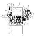
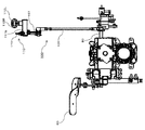
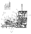
ここに、図1は本発明における実施の形態のトラクターの左側面図であり、図2は本発明における実施の形態のトラクターのステップフロア40近傍の部分上面図であり、図3は本発明における実施の形態のトラクターの操作コラムカバー33近傍の部分斜視図(その一)であり、図4は本発明における実施の形態のトラクターの上面図であり、図5は本発明における実施の形態のトラクターの正面図である。
FIG. 1 is a left side view of the tractor according to the embodiment of the present invention, FIG. 2 is a partial top view in the vicinity of the
なお、図2においては、以下の説明がより理解しやすくなるように、ステップフロア40などは図示されていない。
In FIG. 2, the
車体前部のボンネット1の内部には、エンジン2(図2参照)が搭載されている。 An engine 2 (see FIG. 2) is mounted inside the bonnet 1 at the front of the vehicle body.
トランスミッションケ−ス20(図2参照)は、ステップフロア40の下側に設けられている。
The transmission case 20 (see FIG. 2) is provided below the
HST11(図2参照)を収納するHSTケース10(図2参照)は、トランスミッションケ−ス20の前側に設けられている。
An HST case 10 (see FIG. 2) that houses the HST 11 (see FIG. 2) is provided on the front side of the
エンジン2の回転動力は、HST11を介してトランスミッションケ−ス20の内部の変速装置に伝えられる。そして、同変速装置で減速された回転動力は、左右の前輪3Lおよび3R、ならびに左右の後輪4Lおよび4Rに伝えられる。
The rotational power of the engine 2 is transmitted to the transmission inside the
エンジン2の後方には、前輪3Lおよび3Rを操舵するためのステアリングハンドル32が装備されている。
A steering handle 32 for steering the
ステアリングハンドル32の後方には、運転席31が設けられている。
A
車体後部には、ロータリ耕耘装置などの作業機(図示省略)が3点リンク機構などの機構を利用して装着される。 A working machine (not shown) such as a rotary tiller is mounted on the rear part of the vehicle body using a mechanism such as a three-point link mechanism.
ホースカバー35は、ステアリングハンドル32に接続されたホースを覆っている。
The
操作コラムカバー33の左側のステップフロア40には、作業者の踏み込み操作に応じて後輪4Lおよび4Rの制動を行うためのブレーキペダル50Lおよび50R(図3参照)が配置されている。
On the
操作コラムカバー33の右側のステップフロア40には、車両の前進および後進を切替えるための前後進ペダル60が配置されている。
On the
後に詳述されるように、HST11のHSTトラニオン開度の調節がシーソー式の前後進ペダル60の踏込み操作に応じて行われ、前進増速、中立および後進増速に対応する無段変速が実現される。
As will be described in detail later, the HST trunnion opening degree of the
つぎに、図2および6〜9を主として参照しながら、本実施の形態のトラクターの構成および動作についてより具体的に説明する。 Next, the configuration and operation of the tractor according to the present embodiment will be described more specifically with reference mainly to FIGS. 2 and 6 to 9.
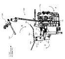
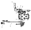
ここに、図6は本発明における実施の形態のトラクターのステップフロア40近傍の部分右側面図であり、図7は本発明における実施の形態のトラクターのステップフロア40近傍の部分背面図であり、図8は本発明における実施の形態のトラクターのステップフロア40近傍の部分左側面図(その一)であり、図9は本発明における実施の形態のトラクターのステップフロア40近傍の部分正面図である。
FIG. 6 is a partial right side view of the vicinity of the
なお、図6〜9においては、以下の説明がより理解しやすくなるように、ステップフロア40のみならず、エンジン2、HSTケース10およびトランスミッションケ−ス20なども図示されていない。
6 to 9, not only the
まず、図6および7を主として参照しながら、HST11、およびHST11のHSTトラニオン軸12と連結された前後進ペダル60について説明する。
First, the forward /
HSTトラニオンアーム13は、HSTトラニオン軸12の右側の端部12a(図2参照)に連結されている。
The
HSTトラニオンアーム13と、端部12aと、の連結は、固定的に行われている。
The connection between the
前後方向の連結軸70は、HSTトラニオンアーム13と、前後進ペダル60のペダル基部61と、を連結している。
The connecting
このように、連結軸70は単一の軸であり、HSTトラニオンアーム13と、前後進ペダル60のペダル基部61と、の連結構成は極めて簡素である。
Thus, the connecting
連結軸70と、HSTトラニオンアーム13と、の連結はピン70aを利用して回動可能に行われており、連結軸70と、ペダル基部61と、の連結はピン70bを利用して回動可能に行われている。
The
連結軸70は、HSTケース10の後部から後方に突出して、トランスミッションケ−ス20の側方を通過している(図2参照)。
The connecting
このように、HSTトラニオンアーム13と、前後進ペダル60のペダル基部61と、の連結構成は、極めて短い距離で実現される。
Thus, the connection configuration between the
前後進ペダル回動軸80は、前後進ペダル60の揺動に応じて回動し、トランスミッションケ−ス20を左右方向に貫通している(図2参照)。
The forward / reverse
このように、トランスミッションケ−ス20の内部の上部空間が有効に利用され、コンパクトな機体レイアウトが実現される。
Thus, the upper space inside the
前後進ペダル回動軸80の右側の端部80aと、ペダル基部61と、の連結は、固定的に行われている。
The connection between the
作業者の右足による踏み込み操作が行われる、前後進ペダル60のペダル踏込部62は、ペダル基部61に連結されている。ペダル基部61と、ペダル踏込部62と、の連結は、ボルト60aおよび60bを利用して固定的に行われている。
A
ただし、ペダル踏込部62には、ボルト60aが貫通する丸孔と、ボルト60bが貫通する長孔と、が設けられており、ペダル基部61へのペダル踏込部62の取り付け角度は調整可能である。
However, the
HSTトラニオン軸12の周りに回動可能なHSTトラニオン板(図示省略)の姿勢は、ペダル踏込部62の姿勢が水平姿勢であるときに、HSTトラニオン開度がゼロである中立姿勢に一致していることが望ましい。
The posture of the HST trunnion plate (not shown) that can rotate around the
そこで、上述された構成要素の連結状態は、ペダル踏込部62の水平姿勢が、HSTトラニオン板の中立姿勢つまりHSTトラニオン軸12の中立姿勢と両立するように調整されている。
Therefore, the connection state of the above-described components is adjusted so that the horizontal posture of the
前後進ペダル60のペダル操作が矢印Bで示された向きである前向きに行われると、HSTトラニオン軸12の回動は矢印Aで示された向きに行われ、前進増速が行われる。
When the pedal operation of the forward /
上述とは対照的に、前後進ペダル60のペダル操作が矢印Bで示された向きと逆の向きである後向きに行われると、HSTトラニオン軸12の回動は矢印Aで示された向きと逆の向きに行われ、後進増速が行われる。
In contrast to the above, when the pedal operation of the forward /
かくして、シーソー式の前後進ペダル60の踏込み操作に応じた、前進増速、中立および後進増速に対応する無段変速が、実現される。
Thus, continuously variable transmission corresponding to forward acceleration, neutral and reverse acceleration according to the depression operation of the seesaw type forward /
ついで、図8を主として参照しながら、HSTトラニオン軸12の中立姿勢を調整するための中立姿勢調整機構90について説明する。
Next, a neutral
中立姿勢調整機構90は、ハブ91、中立プレート92、調整つまみ部材93を有している。
The neutral
前後進ペダル回動軸80の左側の端部80bと、ハブ91と、の連結は、固定的に行われている。
The connection between the
ハブ91と、中立プレート92と、の連結は、ピン90aを利用して回動可能に行われている。
The
中立プレート92と、調整つまみ部材93と、の連結は、固定的に行われている。
The
調整つまみ部材93は、調整支点ピン90bを偏心支点軸として回動可能である。
The
作業者による調整つまみ部材93の調整回動操作が矢印Dで示された向きに行われると、前後進ペダル回動軸80の回動は矢印Cで示された向きに行われ、HSTトラニオン軸12の回動は矢印Aで示された向きに行われる(図6参照)。
When the adjustment rotation operation of the
このような調整回動操作は、HSTトラニオン軸12の中立姿勢が後進増速側にずれてしまった場合に有効である。
Such an adjustment rotation operation is effective when the neutral posture of the
上述とは対照的に、作業者による調整つまみ部材93の調整回動操作が矢印Dで示された向きと逆の向きに行われると、前後進ペダル回動軸80の回動は矢印Cで示された向きと逆の向きに行われ、HSTトラニオン軸12の回動は矢印Aで示された向きと逆の向きに行われる(図6参照)。
In contrast to the above, when the adjustment rotation operation of the
このような調整回動操作は、HSTトラニオン軸12の中立姿勢が前進増速側にずれてしまった場合に有効である。
Such an adjustment rotation operation is effective when the neutral position of the
HSTトラニオン軸12の中立姿勢のずれは頻繁には発生しないので、中立姿勢調整機構90は、通常、工場における組立時、または出荷後のメンテナンスにおける分解後の組付時などに使用される。
Since the neutral posture deviation of the
作業者による調整つまみ部材93の調整回動操作が完了した後に、ペダル基部61へのペダル踏込部62の取り付け角度が、ペダル踏込部62の水平姿勢がHSTトラニオン軸12の中立姿勢と両立するように調整されることが望ましい。
After the operator completes the adjustment turning operation of the
ついで、図8および9を主として参照しながら、前後進ペダル回動軸80の回動角度、すなわち、HSTトラニオン軸12の回動角度を固定して車両走行速度を一定にするための構成について説明する。
Next, a configuration for fixing the rotation angle of the forward / reverse
もちろん、リンク機構固定部材110の接続部である接続プレート111がリンク機構100の上端部である上端プレート107に当接する位置は、複数個の箇所に、HSTトラニオン軸12の回動角度に対応して、連続的または離散的に設けられている。
Of course, the position where the
リンク機構100のアーム101は、前後進ペダル回動軸80の左側の端部80bに連結されている。
The
より具体的に説明すると、つぎの通りである。 More specifically, it is as follows.
すなわち、リンク機構100は、アーム101、ロッド102、クルーズプレート103、回動アーム部材104(図2参照)、プレート105、ロッド106および上端プレート107を有している。
That is, the
端部80bと、アーム101と、の連結は、固定的に行われている。
The connection between the
アーム101と、ロッド102と、の連結は、ピン100aを利用して回動可能に行われている。
The connection between the
ロッド102と、クルーズプレート103と、の連結は、ピン100bを利用して回動可能に行われている。
The
クルーズプレート103と、回動アーム部材104と、の連結は、固定的に行われている。
The connection between the
回動アーム部材104は、調整支点ピン90bを支点軸として回動可能である。
The
なお、回動アーム部材104および調整つまみ部材93はそれぞれ前後進ペダル回動軸80の回動に応じ独立して回動するが、調整支点ピン90bは回動アーム部材104および調整つまみ部材93の共通の支点軸であり、部品点数が削減されている。
The
回動アーム部材104と、プレート105と、の連結は、固定的に行われている。
The
プレート105と、ロッド106と、の連結は、ピン100cを利用して回動可能に行われている。
The connection between the
ロッド106と、上端プレート107と、の連結は、ピン100dを利用して回動可能に行われている。
The
上端プレート107は、支点ピン100eを支点軸として回動可能である。
The
前後進ペダル60のペダル操作が矢印Bで示された向きである前向きに行われる(図6参照)と、前後進ペダル回動軸80の回動は矢印Cで示された向きに行われ、ロッド106のスライドは矢印Eで示された向きである上向きに行われ、上端プレート107の回動は矢印Fで示された向きである下向きに行われる。
When the pedal operation of the forward /
上述とは対照的に、前後進ペダル60のペダル操作が矢印Bで示された向きと逆の向きである後向きに行われる(図6参照)と、前後進ペダル回動軸80の回動は矢印Cで示された向きと逆の向きに行われ、ロッド106のスライドは矢印Eで示された向きと逆の向きである下向きに行われ、上端プレート107の回動は矢印Fで示された向きと逆の向きである上向きに行われる。
In contrast to the above, when the pedal operation of the forward /
リンク機構固定部材110は、上端プレート107と選択的に着脱自在なリンク機構接続を行うことによって上端プレート107の位置を選択的に固定する接続プレート111を有している。
The link
リンク機構固定部材操作レバー120は、作業者の指示に応じて接続プレート111を移動させることによってリンク機構接続を行わせる。
The link mechanism fixing
より具体的に説明すると、つぎの通りである。 More specifically, it is as follows.
すなわち、接続プレート111は、上端プレート107の歯状部107aと噛み合うことによってリンク機構接続を行う歯状部111aを有している。
In other words, the
接続プレート111が溶接などにより固定的に連結された支点ハブ111bは、回動軸110aに遊嵌されており、回動軸110aの周りに回動可能である。
The
支点ハブ111bと、リンク機構固定部材操作レバー120と、の連結は、固定的に行われている。
The connection between the
リンク機構固定部材操作レバー120のレバー操作が矢印Gで示された向きである上向きに行われると、接続プレート111の回動は矢印Hで示された向きである下向きに行われ、リンク機構接続が実行される。
When the lever operation of the link mechanism fixing
上述とは対照的に、リンク機構接続が実行されているときに、リンク機構固定部材操作レバー120のレバー操作が矢印Gで示された向きと逆の向きである下向きに行われると、接続プレート111の回動は矢印Hで示された向きと逆の向きである上向きに行われ、リンク機構接続は解除される。
In contrast to the above, when the link mechanism connection is being performed, if the lever operation of the link mechanism fixing
上述された構成要素の連結状態は、リンク機構接続が、前後進ペダル60の踏込み操作に応じて前進が行われているときにのみ実行可能であるように調整されていてもよい。
The connection state of the components described above may be adjusted so that the link mechanism connection can be executed only when the forward movement is performed according to the depression operation of the forward /
なお、リンク機構固定部材操作レバー120は回動軸110aよりも後下方にあり、接続プレート111は回動軸110aよりも前上方にあることが、望ましい。
It is desirable that the link mechanism fixing
これは、リンク機構固定部材操作レバー120のレバー操作が上向きに行われたとき、接続プレート111の回動は下向きに行われ、接続プレート111の歯状部111aが上端プレート107の歯状部107aを上から押さえつける構成を実現しやすいからである。
This is because when the lever operation of the link mechanism fixing
また、リンク機構固定部材操作レバー120は、たとえば、機体左右中央部にあるホースカバー35の近傍に設けられることが、望ましい。
Moreover, it is desirable that the link mechanism fixing
これは、リンク機構固定部材操作レバー120が作業者に近接し、リンク機構固定部材操作レバー120の操作が作業者にとって容易になるのみならず、後述されるように、リンク機構接続解除ベアリング112Lおよび112R(図11参照)がリンク機構接続解除プレート131Lおよび131R(図11参照)に近接している構成を実現しやすいからである。
This is because not only the link mechanism fixing
このように、車両走行速度の変動が抑制されるオートクルーズ機能は、足によるペダル操作ではなく、手によるレバー操作によって実行または解除されるので、作業者にとって複雑な、たとえば、両足を同時に使用する必要がある状況の発生が抑制される。 Thus, the auto-cruise function in which fluctuations in the vehicle traveling speed are suppressed is executed or canceled not by pedal operation by foot but by lever operation by hand, so that it is complicated for an operator, for example, both feet are used simultaneously. Occurrence of a necessary situation is suppressed.
リンク機構固定部材110およびリンク機構固定部材操作レバー120に関するさらなる構成および動作については、リンク機構接続解除機構130に関する構成および動作と併せて後に説明する。
Further configurations and operations related to the link
つぎに、図10および11を主として参照しながら、本実施の形態のトラクターの構成および動作についてさらにより具体的に説明する。 Next, the configuration and operation of the tractor according to the present embodiment will be described more specifically with reference mainly to FIGS.
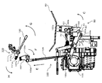
ここに、図10は本発明における実施の形態のトラクターのステップフロア40近傍の部分左側面図(その二)であり、図11は本発明における実施の形態のトラクターの操作コラムカバー33近傍の部分斜視図(その二)である。
FIG. 10 is a partial left side view in the vicinity of the
なお、図11においては、以下の説明がより理解しやすくなるように、ダッシュパネル34(図3参照)などは図示されていない。 In FIG. 11, the dash panel 34 (see FIG. 3) and the like are not shown so that the following description can be easily understood.
ブレーキペダル50Lおよび50R(図11参照)の少なくとも一方の踏み込みが行われたとき、リンク機構接続が行われている場合には、リンク機構接続を解除するリンク機構接続解除機構130について説明する。
When at least one of the
リンク機構接続解除機構130は、ブレーキペダル50Lおよび50Rの少なくとも一方の揺動に応じて移動しリンク機構固定部材110のリンク機構接続解除ベアリング112Lおよび112R(図11参照)にそれぞれ当接する、第一プレートおよび第二プレートとしてのリンク機構接続解除プレート131Lおよび131R(図11参照)を有している。
The link mechanism
つまり、リンク機構接続解除機構130は、リンク機構接続解除プレート131Lおよび131Rを、二つのブレーキペダル50Lおよび50Rに対応して有している。
That is, the link mechanism
そして、リンク機構固定部材110は、リンク機構接続解除プレート131Lおよび131Rによって当接される、第一被当接部および第二被当接部としてのリンク機構接続解除ベアリング112Lおよび112Rを、二つのブレーキペダル50Lおよび50Rに対応して有している。
The link
より具体的に説明すると、つぎの通りである。 More specifically, it is as follows.
すなわち、リンク機構固定部材110は、支点ハブ111bに固定的に連結されたリンク機構接続解除ベアリング112Lおよび112Rを有している。
That is, the link
リンク機構接続解除ベアリング112Lおよび112Rの取付位置は、これらの取付がプレート113、ならびにボルト113aおよび113bを利用して行われているので、調整可能である。
The attachment positions of the link mechanism
リンク機構接続解除プレート131Lおよび131Rが溶接などによりそれぞれ固定的に連結された支点ハブ131Laおよび131Ra(図11参照)は、回動軸130aに遊嵌されており、回動軸130aの周りにそれぞれ回動可能である。
The fulcrum hubs 131La and 131Ra (see FIG. 11), to which the link mechanism
なお、回動軸130aと回動軸110aとはほぼ平行であり、回動軸130aと回動軸110aとの間の距離はあまり大きくないことが望ましい。
It is desirable that the
これは、リンク機構接続解除ベアリング112Lおよび112Rがリンク機構接続解除プレート131Lおよび131Rに近接し、リンク機構接続解除プレート131Lおよび131Rの長さが短くなる構成を実現しやすいからである。
This is because it is easy to realize a configuration in which the link mechanism
支点ハブ131Laおよび131Raと、ブレーキペダル50Lおよび50Rと、の連結は、それぞれ固定的に行われている。
The connection between the fulcrum hubs 131La and 131Ra and the
ブレーキペダル50Lのペダル操作が矢印Iで示された向きである前向きに行われると、支点ハブ131Laの回動は矢印Jで示された向きに行われ、リンク機構接続解除プレート131Lの回動は矢印Kで示された向きである下向きに行われる。
When the pedal operation of the
そして、リンク機構接続が行われている場合には、リンク機構接続解除プレート131Lはリンク機構接続解除ベアリング112Lに当接し、接続プレート111の回動は矢印Hで示された向きと逆の向きである上向きに行われ(図8参照)、リンク機構接続は解除される。
When the link mechanism is connected, the link mechanism
上述とは対照的に、ブレーキペダル50Rのペダル操作が矢印Iで示された向きである前向きに行われると、支点ハブ131Raの回動は矢印Jで示された向きに行われ、リンク機構接続解除プレート131Rの回動は矢印Kで示された向きである下向きに行われる。
In contrast to the above, when the pedal operation of the
そして、リンク機構接続が行われている場合には、リンク機構接続解除プレート131Rはリンク機構接続解除ベアリング112Rに当接し、接続プレート111の回動は矢印Hで示された向きと逆の向きである上向きに行われ、リンク機構接続は解除される。
When the link mechanism is connected, the link mechanism
もちろん、ブレーキペダル50Lおよび50Rの少なくとも一方の踏み込みが行われたとき、ブレーキペダル50Lおよび50Rがブレーキペダル連結器51(図11参照)によって連結されている場合には、ブレーキペダル50Lおよび50Rの両方が揺動する。
Of course, when the
なお、ブレーキペダル50Lおよび50Rは回動軸130aよりも後下方にあり、回動軸130aは回動軸110aよりも前上方にあることが、望ましい。
It is desirable that the
これは、たとえば、ブレーキペダル50Lのペダル操作が前向きに行われたとき、リンク機構接続解除プレート131Lの回動が下向きに行われ、リンク機構接続解除プレート131Lがリンク機構接続解除ベアリング112Lを上から押さえつけるように当接が行われる構成を実現しやすいからである。
For example, when the pedal operation of the
リンク機構接続解除プレート131Lによって当接されたリンク機構接続解除ベアリング112Lが回動する構成が採用されていれば、当接による衝撃が緩和されるので、リンク機構接続は円滑に解除され、より望ましい。
If the structure in which the link mechanism connection release bearing 112L abutted by the link mechanism
このように、オートクルーズ機能が実行されているときには、前後進ペダル60のペダル操作に右足を使用する必要はなく、ブレーキペダル50Lおよび50Rの少なくとも一方のペダル操作に左足を使用するだけでオートクルーズ機能を解除することができるので、両足を同時に使用する必要がある状況の発生が抑制される。
As described above, when the auto-cruise function is being executed, it is not necessary to use the right foot for pedal operation of the forward /
ブレーキペダル50Lおよび50Rの少なくとも一方のペダル操作にともなうオートクルーズ機能の自動的な解除は、必須の仕様ではない。
The automatic release of the auto-cruise function accompanying the operation of at least one of the
しかしながら、緊急停止などの目的で行われることもあるブレーキペダル50Lおよび50Rのペダル操作の際には、オートクルーズ機能が実行されていれば、その実行されているオートクルーズ機能を解除することが安全性などの観点からより望ましい。
However, when the
本実施の形態においては、ブレーキペダル50Lおよび50Rの少なくとも一方のペダル操作の際には、オートクルーズ機能の自動的な解除が行われるので、作業者はオートクルーズ機能を解除するためのリンク機構固定部材操作レバー120のレバー操作をわざわざ行う必要はない。
In the present embodiment, the auto-cruise function is automatically released when operating at least one of the
もちろん、作業者がリンク機構接続を実行するためのリンク機構固定部材操作レバー120のレバー操作を必要に応じて行えば、オートクルーズ機能は再び実行される。
Of course, if the operator performs the lever operation of the link mechanism fixing
なお、リターンスプリング121(図11参照)による付勢がリンク機構固定部材操作レバー120に対して行われているので、リンク機構接続が解除されると、リンク機構固定部材操作レバー120は初期位置に戻る。
In addition, since urging | biasing by the return spring 121 (refer FIG. 11) is performed with respect to the link mechanism fixing
また、リターンスプリング52Lおよび52R(図11参照)による付勢がブレーキペダル50Lおよび50Rに対してそれぞれ行われているので、ペダル操作が行われなくなると、ブレーキペダル50Lおよび50Rは初期位置に戻る。
Further, since the urging forces by the return springs 52L and 52R (see FIG. 11) are respectively applied to the
このように、極めて簡素な構成で、二つのブレーキペダル50Lおよび50Rの少なくとも一方のペダル操作を行うだけでオートクルーズ機能を解除することができる。
In this way, with an extremely simple configuration, the auto-cruise function can be canceled simply by operating at least one of the two
なお、本実施の形態においては、前後進ペダル60と、HSTトラニオンアーム13と、はステップフロア40の右側に設けられており、リンク機構100と、ブレーキペダル50Lおよび50Rと、はステップフロア40の左側に設けられている。
In the present embodiment, the forward /
しかしながら、このような構成については、左右がそっくり入れ替わっていてもよい。 However, in such a configuration, the left and right sides may be completely interchanged.
つまり、前後進ペダル60と、HSTトラニオンアーム13と、はステップフロア40の左側に設けられており、リンク機構100と、ブレーキペダル50Lおよび50Rと、はステップフロア40の右側に設けられていてもよい。
That is, the forward /
また、本実施の形態のオートクルーズ機能は、ブレーキペダル50Lおよび50Rの踏み込み操作以外の、前後進ペダル60の前進側への踏み込み操作、すなわち、増速側への操作でも解除される。すなわち、オートクルーズ中において、前後進ペダル60が前進側に踏み込まれると、リンク機構が動作し、接続プレート111と上端プレート107との接続が解除される。
Further, the auto-cruise function of the present embodiment can also be canceled by an operation of depressing the forward /
なお、本実施の形態では、オートクルーズ中において、前後進ペダルが後進側に踏み込まれてもオートクルーズ機能は解除されず、前後進ペダルが前進側に踏み込まれるとリンク機構が動作してオートクルーズ機能が解除されるが、当該作用の詳細な説明は省略する。 In this embodiment, during auto-cruise, the auto-cruise function is not canceled even if the forward / reverse pedal is depressed to the reverse side. When the forward / reverse pedal is depressed to the forward side, the link mechanism operates and the auto-cruise is activated. Although the function is released, detailed description of the operation is omitted.
本発明におけるトラクターは、HSTの制御をより簡素な機構を利用して行うことが可能であり、たとえば圃場内での作業を行うトラクターに利用する目的に有用である。 The tractor in the present invention can control the HST using a simpler mechanism, and is useful for the purpose of, for example, a tractor that performs work in a field.
1 ボンネット
2 エンジン
3L、3R 前輪
4L、4R 後輪
10 HSTケース
11 HST
12 HSTトラニオン軸
13 HSTトラニオンアーム
20 トランスミッションケ−ス
31 運転席
32 ステアリングハンドル
33 操作コラムカバー
34 ダッシュパネル
35 ホースカバー
40 ステップフロア
50L、50R ブレーキペダル
51 ブレーキペダル連結器
52L、52R リターンスプリング
60 前後進ペダル
61 ペダル基部
62 ペダル踏込部
70 連結軸
80 前後進ペダル回動軸
90 中立姿勢調整機構
91 ハブ
92 中立プレート
93 調整つまみ部材
100 リンク機構
101 アーム
102 ロッド
103 クルーズプレート
104 回動アーム部材
105 プレート
106 ロッド
107 上端プレート
110 リンク機構固定部材
111 接続プレート
112L、112R リンク機構接続解除ベアリング
113 プレート
120 リンク機構固定部材操作レバー
121 リターンスプリング
130 リンク機構接続解除機構
131L、131R リンク機構接続解除プレート
1 Bonnet 2
12
Claims (3)
前記トランスミッションケースの前側に設けられた、HSTを収納するHSTケースと、
前記HSTのHSTトラニオン軸と連結され、前記ステップフロアの左側および右側の内の一方の側に設けられた前後進ペダルと、
前記前後進ペダルの揺動に応じて回動し、前記トランスミッションケースを左右方向に貫通している前後進ペダル回動軸と、
前記前後進ペダル回動軸の、前記ステップフロアの左側および右側の内の他方の側に連結されたリンク機構と、
前記リンク機構の位置を選択的に固定する接続部を有するリンク機構固定部材と、
作業者の指示に応じて前記リンク機構固定部材の前記接続部を移動させることによって前記リンク機構接続を行わせるリンク機構固定部材操作レバーと、
ブレーキペダルと、
前記リンク機構固定部材が前記リンク機構に当接している場合に、前記ブレーキペダルの踏み込みが行われると、前記リンク機構固定部材を前記リンク機構から離れる方向に移動させるリンク機構接続解除機構と、
を備え、
前記リンク機構固定部材操作レバーの操作により、前記リンク機構固定部材が前記リンク機構に当接することによって前記HSTトラニオン軸の回動を規制する構成とし、
前記リンク機構接続解除機構は、前記ブレーキペダルの踏み込みが行われると、前記リンク機構固定部材に当接することによって、前記リンク機構固定部材を前記リンク機構から離れる方向に移動させるリンク機構接続解除プレートを備え、
前記ブレーキペダルは、左側の車輪のブレーキに対応した左ブレーキペダルと、右側の車輪のブレーキに対応した右ブレーキペダルと、を備え、
前記リンク機構接続解除プレートは、前記左ブレーキペダルに対応する第一プレートと、前記右ブレーキペダルに対応する第二プレートと、を備えることを特徴とするトラクター。 A transmission case provided below the step floor;
An HST case for storing the HST provided on the front side of the transmission case;
A forward / reverse pedal connected to the HST trunnion shaft of the HST and provided on one of the left and right sides of the step floor;
A forward / reverse pedal pivoting shaft that pivots in response to swinging of the forward / reverse pedal and penetrates the transmission case in the lateral direction;
A link mechanism connected to the other side of the left and right sides of the step floor of the forward / reverse pedal rotation shaft;
A link mechanism fixing member having a connection portion for selectively fixing the position of the link mechanism;
A link mechanism fixing member operating lever that causes the link mechanism to be connected by moving the connecting portion of the link mechanism fixing member in accordance with an instruction from an operator;
A brake pedal,
A link mechanism connection releasing mechanism that moves the link mechanism fixing member in a direction away from the link mechanism when the brake pedal is depressed when the link mechanism fixing member is in contact with the link mechanism;
Equipped with a,
The operation of the link mechanism fixing member operation lever is configured to regulate the rotation of the HST trunnion shaft by the link mechanism fixing member coming into contact with the link mechanism,
The link mechanism connection release mechanism includes a link mechanism connection release plate that moves the link mechanism fixing member in a direction away from the link mechanism by contacting the link mechanism fixing member when the brake pedal is depressed. Prepared,
The brake pedal includes a left brake pedal corresponding to a left wheel brake, and a right brake pedal corresponding to a right wheel brake,
The link mechanism disconnect plate, tractors and the first plate corresponding to the left brake pedal, and a second plate corresponding to the right brake pedal, characterized Rukoto equipped with.
前記被当接部は、前記第一プレートによって当接される第一被当接部と、前記第二プレートによって当接される第二被当接部と、を備えることを特徴とする、請求項2に記載のトラクター。 The link mechanism fixing member includes a contacted portion that is contacted by the link mechanism connection release plate ,
The abutted portion may be a first abutted portion to be abutted by said first plate, a second abutted portion to be abutted by said second plate, wherein Rukoto provided with, The tractor according to claim 2.
Priority Applications (1)
| Application Number | Priority Date | Filing Date | Title |
|---|---|---|---|
| JP2014189835A JP6375813B2 (en) | 2014-09-18 | 2014-09-18 | Tractor |
Applications Claiming Priority (1)
| Application Number | Priority Date | Filing Date | Title |
|---|---|---|---|
| JP2014189835A JP6375813B2 (en) | 2014-09-18 | 2014-09-18 | Tractor |
Publications (2)
| Publication Number | Publication Date |
|---|---|
| JP2016060363A JP2016060363A (en) | 2016-04-25 |
| JP6375813B2 true JP6375813B2 (en) | 2018-08-22 |
Family
ID=55796872
Family Applications (1)
| Application Number | Title | Priority Date | Filing Date |
|---|---|---|---|
| JP2014189835A Active JP6375813B2 (en) | 2014-09-18 | 2014-09-18 | Tractor |
Country Status (1)
| Country | Link |
|---|---|
| JP (1) | JP6375813B2 (en) |
Family Cites Families (5)
| Publication number | Priority date | Publication date | Assignee | Title |
|---|---|---|---|---|
| JPS6138831Y2 (en) * | 1979-07-24 | 1986-11-08 | ||
| JPS5657124A (en) * | 1979-10-12 | 1981-05-19 | Kubota Ltd | Speed change operating device for running of working vehicle |
| JPH1191391A (en) * | 1997-09-18 | 1999-04-06 | Kubota Corp | Work vehicle |
| JP4784090B2 (en) * | 2004-12-22 | 2011-09-28 | 井関農機株式会社 | Work vehicle |
| JP2007137323A (en) * | 2005-11-21 | 2007-06-07 | Yanmar Co Ltd | Working vehicle |
-
2014
- 2014-09-18 JP JP2014189835A patent/JP6375813B2/en active Active
Also Published As
| Publication number | Publication date |
|---|---|
| JP2016060363A (en) | 2016-04-25 |
Similar Documents
| Publication | Publication Date | Title |
|---|---|---|
| JP4866307B2 (en) | Work vehicle | |
| JP6499111B2 (en) | Work vehicle | |
| JP2648262B2 (en) | Shifting structure of work vehicle | |
| JP6398446B2 (en) | Tractor | |
| JP5959461B2 (en) | Vehicle speed control device for work vehicles | |
| JP6375813B2 (en) | Tractor | |
| JP6566101B2 (en) | Tractor | |
| JP5069669B2 (en) | Work vehicle | |
| JP4917854B2 (en) | Work vehicle | |
| JP5356348B2 (en) | Forward / reverse switching operation device for traveling vehicle | |
| JP2013067231A (en) | Operating device of tractor | |
| JP2013067239A (en) | Speed maintenance releasing structure for working vehicle | |
| KR20160038573A (en) | Engine speed control apparatus of agriculture vehicle | |
| JP7809045B2 (en) | Work vehicle | |
| JP2008006902A (en) | Operation link structure | |
| JP2015123760A (en) | Service car | |
| JP2007313953A (en) | Working vehicle | |
| JP2018131156A (en) | Working vehicle | |
| JP2024063566A (en) | Work vehicle | |
| JP2017043248A (en) | Work vehicle | |
| JP4797382B2 (en) | Shift adjustment device for work vehicle | |
| JP6710960B2 (en) | Work vehicle | |
| JP2014082980A (en) | Ground operation tool in sulky type traveling vehicle | |
| JP2024071111A (en) | Work vehicle | |
| JP2021185762A (en) | Operation device for work vehicle |
Legal Events
| Date | Code | Title | Description |
|---|---|---|---|
| A621 | Written request for application examination |
Free format text: JAPANESE INTERMEDIATE CODE: A621 Effective date: 20170421 |
|
| A977 | Report on retrieval |
Free format text: JAPANESE INTERMEDIATE CODE: A971007 Effective date: 20180112 |
|
| A131 | Notification of reasons for refusal |
Free format text: JAPANESE INTERMEDIATE CODE: A131 Effective date: 20180116 |
|
| A521 | Written amendment |
Free format text: JAPANESE INTERMEDIATE CODE: A523 Effective date: 20180313 |
|
| TRDD | Decision of grant or rejection written | ||
| A01 | Written decision to grant a patent or to grant a registration (utility model) |
Free format text: JAPANESE INTERMEDIATE CODE: A01 Effective date: 20180626 |
|
| A61 | First payment of annual fees (during grant procedure) |
Free format text: JAPANESE INTERMEDIATE CODE: A61 Effective date: 20180709 |
|
| R150 | Certificate of patent or registration of utility model |
Ref document number: 6375813 Country of ref document: JP Free format text: JAPANESE INTERMEDIATE CODE: R150 |

