JP6362083B2 - Recording method, recording apparatus, image processing apparatus, and image processing method - Google Patents
Recording method, recording apparatus, image processing apparatus, and image processing method Download PDFInfo
- Publication number
- JP6362083B2 JP6362083B2 JP2014094815A JP2014094815A JP6362083B2 JP 6362083 B2 JP6362083 B2 JP 6362083B2 JP 2014094815 A JP2014094815 A JP 2014094815A JP 2014094815 A JP2014094815 A JP 2014094815A JP 6362083 B2 JP6362083 B2 JP 6362083B2
- Authority
- JP
- Japan
- Prior art keywords
- ink
- recording
- dots
- recording medium
- preliminary ejection
- Prior art date
- Legal status (The legal status is an assumption and is not a legal conclusion. Google has not performed a legal analysis and makes no representation as to the accuracy of the status listed.)
- Active
Links
Images


Classifications
-
- B—PERFORMING OPERATIONS; TRANSPORTING
- B41—PRINTING; LINING MACHINES; TYPEWRITERS; STAMPS
- B41J—TYPEWRITERS; SELECTIVE PRINTING MECHANISMS, i.e. MECHANISMS PRINTING OTHERWISE THAN FROM A FORME; CORRECTION OF TYPOGRAPHICAL ERRORS
- B41J2/00—Typewriters or selective printing mechanisms characterised by the printing or marking process for which they are designed
- B41J2/005—Typewriters or selective printing mechanisms characterised by the printing or marking process for which they are designed characterised by bringing liquid or particles selectively into contact with a printing material
- B41J2/01—Ink jet
- B41J2/21—Ink jet for multi-colour printing
- B41J2/2121—Ink jet for multi-colour printing characterised by dot size, e.g. combinations of printed dots of different diameter
-
- B—PERFORMING OPERATIONS; TRANSPORTING
- B41—PRINTING; LINING MACHINES; TYPEWRITERS; STAMPS
- B41J—TYPEWRITERS; SELECTIVE PRINTING MECHANISMS, i.e. MECHANISMS PRINTING OTHERWISE THAN FROM A FORME; CORRECTION OF TYPOGRAPHICAL ERRORS
- B41J2/00—Typewriters or selective printing mechanisms characterised by the printing or marking process for which they are designed
- B41J2/005—Typewriters or selective printing mechanisms characterised by the printing or marking process for which they are designed characterised by bringing liquid or particles selectively into contact with a printing material
- B41J2/01—Ink jet
- B41J2/135—Nozzles
- B41J2/165—Preventing or detecting of nozzle clogging, e.g. cleaning, capping or moistening for nozzles
- B41J2/16517—Cleaning of print head nozzles
- B41J2/1652—Cleaning of print head nozzles by driving a fluid through the nozzles to the outside thereof, e.g. by applying pressure to the inside or vacuum at the outside of the print head
- B41J2/16526—Cleaning of print head nozzles by driving a fluid through the nozzles to the outside thereof, e.g. by applying pressure to the inside or vacuum at the outside of the print head by applying pressure only
- B41J2002/16529—Idle discharge on printing matter
Description
本発明は、インクを用いて画像を記録する記録方法、記録装置、画像処理装置、画像処理方法及びプログラムに関する。 The present invention relates to a recording method for recording an image using ink, a recording apparatus, an image processing apparatus, an image processing method, and a program.
インクジェット記録装置では、記録ヘッドの吐出口付近のインクが乾燥することによって増粘し、吐出不良が生じることがある。これに対し、画像記録前に、インク吸収体などで構成されるインク受けに増粘したインクを排出する予備吐出という動作を実施する方法が知られている。記録媒体に対して記録ヘッドを移動させて画像を記録する、所謂シリアルプリンタにおいては、記録媒体外に設けられた所定の位置に対して予備吐出を行うのが一般的である。 In an ink jet recording apparatus, ink near a discharge port of a recording head may increase in viscosity due to drying, resulting in a discharge failure. On the other hand, there is known a method of performing an operation of preliminary discharge for discharging the thickened ink to an ink receiver composed of an ink absorber or the like before image recording. In a so-called serial printer that records an image by moving a recording head with respect to a recording medium, it is common to perform preliminary ejection at a predetermined position provided outside the recording medium.
一方、記録媒体の幅を満たすように記録ヘッドを複数配置し、固定された記録ヘッドに対して記録媒体を搬送することにより画像を記録する、所謂フルマルチプリンタが知られている。このフルマルチプリンタの場合、記録媒体外に行う予備吐出だけでは予備吐出を行う時間間隔が長くなってしまうため、吐出性能を維持することが難しい。また、画像記録を中断して記録ヘッドもしくはインク受けを移動させることになるため、スループットが低下するという課題がある。これに対し、画像を記録する記録媒体上に予備吐出を実施する、所謂紙面予備吐出が知られている。この紙面予備吐は、記録開始後であっても記録媒体への記録を中断せずに画像記録と予備吐出を並行して実施できることから、記録される画像の品位維持とスループット低下抑制とを両立させることができる。 On the other hand, a so-called full multi-printer is known in which a plurality of recording heads are arranged so as to fill the width of the recording medium, and an image is recorded by conveying the recording medium to a fixed recording head. In the case of this full multi-printer, it is difficult to maintain the discharge performance because the time interval for performing the preliminary discharge becomes long only by the preliminary discharge performed outside the recording medium. Further, since the image recording is interrupted and the recording head or the ink receiver is moved, there is a problem that the throughput is lowered. On the other hand, so-called paper surface preliminary discharge, in which preliminary discharge is performed on a recording medium on which an image is recorded, is known. This pre-discharge on the paper allows both image recording and pre-discharge to be performed in parallel without interrupting recording on the recording medium even after the start of recording. Can be made.
しかしながら、紙面予備吐は、画像が形成される記録媒体上にインクを吐出するために、インクの濃度や量によっては形成されたドットがユーザーに視認されてしまい、記録品位を低下させる場合がある。このような課題に対し、特許文献1には、カラー画像上に紙面予備吐を行う際に、紙面予備吐の該当データを削除する方法が記載されている。この方法により、ドット径が大きくなること抑制するため、紙面予備吐によって形成されたドットが視認されにくくなる。また、特許文献2には、記録ヘッドに対して予備吐出が必要になったノズルに対向する位置に黒インクを吐出するデータが存在するとき、紙面予備吐のカラードットを黒インクのドットと同位置に重ねて形成することが記載されている。
However, the preliminary discharge on the paper discharges ink onto a recording medium on which an image is formed, so that the formed dots may be visually recognized by the user depending on the density and amount of the ink, which may reduce the recording quality. . To deal with such a problem,
しかしながら、特許文献1及び特許文献2は、記録画像においてインクの吐出データが存在する位置に紙面予備吐を行う方法であり、記録画像のドットが形成されない領域においては紙面予備吐により形成されたドットの視認性を低下させることができない。特に、紙面予備吐により形成されたドットの明度と、記録媒体そのものの明度や周辺に形成された画像の明度と、の差が大きい場合に、紙面予備吐のドットが視認されやすくなってしまう。
However,
このような課題を解決するため、本発明は、第1インクと、前記第1インクよりも明度が高い第2インクと、前記第1インクよりも明度が高く、前記第2インクよりも明度が低い第3インクと、を吐出する記録ヘッドを用いて記録媒体上に画像を記録する際に、前記画像が形成される所定領域に対して、前記記録ヘッドからのインクの吐出状態を維持するために、前記画像の記録に寄与しない予備吐出を行う記録方法であって、前記記録媒体が第1の記録媒体である場合には、予備吐出により前記所定領域に形成される前記第1インクのドットが、予備吐出により前記所定領域に形成される前記第2インクのドットと重なり、且つ、予備吐出により前記所定領域に形成される前記第3インクのドットと重ならないように前記予備吐出を行い、前記記録媒体が前記第1の記録媒体よりもインクが浸透しにくい第2の記録媒体である場合には、予備吐出により前記所定領域に形成される前記第1インクのドットが、予備吐出により前記所定領域に形成される前記第2インクのドットと重ならないように前記予備吐出を行うことを特徴とする記録方法である。 In order to solve such problems, the present invention provides a first ink, a second ink having a higher lightness than the first ink, a lightness higher than the first ink, and a lightness higher than the second ink. When recording an image on a recording medium using a recording head that discharges a low third ink, the ink ejection state from the recording head is maintained for a predetermined area where the image is formed. In addition, in the recording method for performing preliminary ejection that does not contribute to the recording of the image, and the recording medium is a first recording medium, the dots of the first ink formed in the predetermined region by preliminary ejection. The preliminary ejection is performed so that it overlaps with the dots of the second ink formed in the predetermined area by the preliminary ejection and does not overlap with the dots of the third ink formed in the predetermined area by the preliminary ejection, When the recording medium is a second recording medium in which ink is less likely to permeate than the first recording medium, the dots of the first ink formed in the predetermined area by preliminary ejection are In the recording method, the preliminary ejection is performed so as not to overlap with the dots of the second ink formed in a predetermined region.
上記構成により、紙面予備吐により形成されたドットの明度と、このドットの周辺の形成されている画像や記録媒体そのものの明度と、の差が小さくなるため、予備吐出により形成されたドットの視認性を低下させることができる。 With the above configuration, the difference between the brightness of the dots formed by the preliminary ejection on the paper and the brightness of the image formed on the periphery of the dots and the recording medium itself is reduced, so that the dots formed by the preliminary ejection are visually recognized. Can be reduced.
(第1実施形態)
以下、図面を参照して本発明の第1実施形態を具体的に説明する。
(First embodiment)
The first embodiment of the present invention will be specifically described below with reference to the drawings.
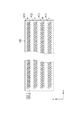
図1は、本実施形態におけるインクジェット記録装置(以下プリンタ)における記録部を説明する図である。記録チップ(吐出基板)100には、インクを吐出するノズルが配列するノズル列101〜104が備えられている。ノズル列101はブラック(K)インク、ノズル列102はシアン(C)インク、ノズル列103はマゼンダ(M)インク、ノズル列104はイエロー(Y)インクにそれぞれ対応する。各ノズル列の構成は同じであるため、以下、ブラックインクのノズル列101の構成について説明する。ノズル列101には、2つのノズル列101−1、101−2が設けられており、各列とも600dpiの解像度でノズルが配列されている。ノズル列101−1とノズル列101−2は、ノズル配列する方向(図中x方向)において、ノズルの配列するピッチが半ピッチずれている。すなわち、x方向に1/1200inchずれて配置されている。従って、この2列のノズル列は、それぞれ1/1200inchずれたラスタを記録するため、ノズルの配列する方向においては1200dpiの記録解像度で画像を記録することができる。本実施形態の記録ヘッドは、熱エネルギーを利用してインクを吐出する記録ヘッドであり、記録素子として熱エネルギーを発生するための電気熱変換体をノズル内に備える。尚、インクを吐出する方式は熱エネルギーを利用する方法に限るものではなく、圧電素子によってインクを吐出する方法等、他の方式であっても良い。
FIG. 1 is a diagram illustrating a recording unit in an ink jet recording apparatus (hereinafter referred to as a printer) in the present embodiment. The recording chip (discharge substrate) 100 includes
図2は、記録ヘッド201と記録媒体202の位置関係を示す図である。記録ヘッド201には、記録媒体の搬送方向に直交する方向に複数の記録チップ100を千鳥状に並べられている。図のx方向において、記録ヘッド201が記録可能な幅は、記録媒体の幅よりも長い。記録媒体はy方向に搬送され、図の下から上に向かって搬送される。記録チップ100には、記録媒体の搬送方向上流側からY、M、C、Kの順にインクが吐出されるようにノズル列が配置されている。すなわち、Y、M、C、Kの順で記録媒体上にインク滴が着弾し、ドットが形成される。
FIG. 2 is a diagram illustrating the positional relationship between the
図5は、プリンタにおいて記録媒体202が搬送される経路を示している。記録媒体格納部501が複数枚の記録媒体をストックしており、ピックアップローラー502により記録媒体が一枚ずつ分離される。そして、中間ローラー503を介して記録媒体202が記録部504に搬送される。記録部504は、前述の記録ヘッド201を備えている。記録部504の直前には、記録媒体検出用のセンサー506が設けられている。記録媒体202の先端が記録媒体検出用センサー506に到達すると、センサー506の信号がONとなり、記録媒体が正常に搬送されているかどうか、すなわち印字可能かどうかを判断する。尚、ピックアップローラー502が駆動した後、所定時間が経過しても記録媒体検出用センサー506が記録媒体202を検知しなかった場合には、搬送が正常に行われていないと判断して記録動作を中断し、ユーザに「紙ジャムエラー」であることを通知する。所定時間以内に記録媒体を検知した場合には、正常に搬送が行われたと判断し、記録媒体の搬送を継続し、記録部504の下を通過させる。記録部504は、搬送された記録媒体に対して画像処理を経て生成された印字データに基づいて各ノズルのインク滴を吐出し、画像を記録する。画像の記録中に記録媒体202が排紙ローラー505まで搬送され、記録媒体検出用のセンサー506が記録媒体の終端を検知する。印字データの終端まで印字動作を行ったところで、排紙ローラー505によって記録媒体202がプリンタから排出される。尚、本実施形態では、記録媒体の搬送を複数のローラーを駆動させる形態について説明したが、ベルトにより搬送される形態であってもよい。
FIG. 5 shows a path along which the
画像を記録しないときは、不図示のキャップ部を用いて、記録部504のノズルが設けられた吐出口面を密閉する。キャップ部で密閉することにより、ノズル内のインクに含まれている水分や溶剤の蒸発を抑制することができ、結果としてインクの固着や異物によるノズルの目詰まりを防止する。また、各ノズルからキャップ部に対して予備吐出を行うことにより、吐出性能を維持することができ、さらには吐出不良の目詰まりを解消することができる。また、不図示のポンプ手段によってキャップ部の内部には負圧を生じさせることによりノズル内のインクを吸引し、キャップ部内に排出させる。これにより、吐出不良を起こしたノズルを回復させることができる。
When the image is not recorded, the ejection port surface provided with the nozzle of the
図7は、プリンタの制御構成を示すブロック図である。パーソナルコンピューター(PC)701や外部メモリ、スキャナやデジタルカメラなどの画像入力機器から、プリンタのIF702を介して多値画像データが入力され、入力されたデータがメモリ707に格納される。メモリ707に格納された多値画像データに対して、画像処理部708による画像処理が施され、インクの吐出または非吐出を示す2値の印字データが生成される。具体的な処理方法は、図8を用いて後に詳しく述べる。印字制御部704は、画像処理部708にて生成された印字データに従って、対応するノズル内の記録素子を駆動させ、インクを吐出させる。これにより、記録媒体上の所定領域に画像が形成される。
FIG. 7 is a block diagram showing the control configuration of the printer. Multi-value image data is input from a personal computer (PC) 701, an external memory, an image input device such as a scanner or a digital camera, via the printer's
図8は、多値画像データに施される画像処理を示すフローチャートである。ステップS801において、メモリ707に格納された多値画像データが画像処理部708に入力される。ここでは、1画素を8bit(256階調)で表現する多値画像データが入力される。そして、ステップS802において、入力された多値画像データがN値の画像データに量子化される。Nは、3以上256未満の自然数であり、ここでは25とする。ステップS803において、量子化された25値の画像データに基づいて、各画素が示す階調値に対応するドット配置パターンを選択する。ドット配置パターンは、ドット形成の有無、すなわちインクの吐出または非吐出を示す2値のパターンである。ドット配置パターンが選択されることにより、2値の印字データが生成される。その後、ステップS804において、2値の印字データを複数のノズル列に分配し、各ノズル列のノズルで吐出すべき2値の吐出データが決定する。そして、ステップS805において、画像記録中におけるノズルからのインクの吐出状態を維持する目的で紙面予備吐を行うための紙面予備吐データを生成する。この紙面予備吐は、画像が記録される領域に対して行われる予備吐出であり、紙面予備吐により形成されるドットは、画像の記録には寄与しない。従って、記録された画像において予備吐出による影響が極力小さくなるように、視認されないような密度で行われることが好ましい。ステップS806において、ステップS804で得られた2値の吐出データとステップS805で生成された紙面予備吐データとの論理和をとり、ノズル内の記録素子を駆動するための吐出データを生成する。そして、生成された吐出データに基づいて、記録媒体上の所定領域に対して画像を記録する。
FIG. 8 is a flowchart showing image processing performed on multi-valued image data. In step S <b> 801, the multivalued image data stored in the
尚、入力階調画像データのN値化処理は、多値誤差拡散法や平均濃度保存法、ディザマトリックス法等、任意の中間調処理方法を用いることができる。また、画像処理部708は、多値画像データから最終的に2値の吐出データを生成できればよく、上述したようなN値化処理を介在させることは必須ではない。例えば、画像処理部708に入力された多値画像データを直接2値の吐出データに変換するような2値化処理を行ってもよい。
It should be noted that any halftone processing method such as a multi-value error diffusion method, an average density storage method, a dither matrix method, or the like can be used for N-value processing of input gradation image data. The
また、本実施形態では、入力された多値画像データに基づく2値の吐出データと紙面予備吐データとの論理和をとる演算を行ったが、本発明はこれに限るものではない。多値画像データにおいて、インクが吐出されない紙白の領域のみに紙面予備吐を行うように、画像データと紙面予備吐データとを排他にするよう、演算してもよい。 Further, in the present embodiment, the arithmetic operation for calculating the logical sum of the binary ejection data based on the input multi-value image data and the paper preliminary ejection data is performed, but the present invention is not limited to this. In the multi-value image data, the calculation may be performed so that the image data and the paper preliminary ejection data are exclusive so that the paper preliminary ejection is performed only on the paper white area where ink is not ejected.
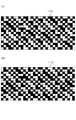
図6(a)は、従来の紙面予備吐データのパターンを示す図である。この予備吐出パターンにおいて、四角で示した領域は1つの画素を示し、インクの吐出または非吐出を定める最小単位である。図中、Y、M、C、Kの文字が入った画素は、各色のインクが吐出され、ドットが形成される画素を示している。従来は、紙面予備吐によるドットを視認されづらくするために、各色についてオフセットする方法が用いられている。 FIG. 6A is a diagram showing a pattern of conventional paper preliminary ejection data. In this preliminary ejection pattern, an area indicated by a square represents one pixel and is a minimum unit that determines ink ejection or non-ejection. In the figure, pixels containing Y, M, C, and K characters indicate pixels on which dots of each color are ejected to form dots. Conventionally, an offset method is used for each color in order to make it difficult to visually recognize dots due to preliminary ejection on the paper surface.
図6(b)は、本実施形態の紙面予備吐データのパターンを示す図である。明度の低いインクと明度の高いインクとが重ねて予備吐出されるように紙面予備吐データを生成することにより、紙面予備吐により形成されるドットを視認されづらくする。本実施形態の予備吐出パターンは、明度の低いブラックインクの紙面予備吐によるドットと、明度の高いイエローインクの紙面予備吐によるドットが、同じ画素に形成される。 FIG. 6B is a diagram showing a pattern of the preliminary ejection data on the sheet according to the present embodiment. By generating paper preliminary ejection data so that low-lightness ink and high-lightness ink are preliminarily ejected, it is difficult to visually recognize dots formed by the preliminary ejection. In the preliminary ejection pattern of the present embodiment, dots due to paper preliminary ejection of black ink with low lightness and dots due to paper preliminary ejection of yellow ink with high lightness are formed in the same pixel.
一般的に、予備吐出パターンは、記録媒体の搬送方向である図中y方向に対して、連続して記録されないように空白画素が挿入される。また、ノズル列方向の罫線(横線)のパターンがテクスチャとして視認されないように、色毎にオフセットする。これにより、テクスチャが視認されづらい画像となる。空白量、オフセット量、オフセット周期は適宜設定すればよい。また、本図のように規則的な紙面予備吐パターンを生成するものに限らず、誤差拡散法などを用いた不規則なパターンを用いても良い。 Generally, in the preliminary ejection pattern, blank pixels are inserted so as not to be continuously recorded in the y direction in the figure, which is the conveyance direction of the recording medium. Further, offset is performed for each color so that a ruled line (horizontal line) pattern in the nozzle row direction is not visually recognized as a texture. As a result, the image is difficult to be visually recognized. The blank amount, offset amount, and offset cycle may be set as appropriate. Further, the pattern is not limited to a regular paper preliminary ejection pattern as shown in the figure, and an irregular pattern using an error diffusion method or the like may be used.
従来、紙面予備吐によるドットを視認されづらくするためには、記録媒体上でできるだけ分散させて配置することが望ましいと考えられていた。これに対し、本発明者らは、ブラックインクとイエローインクを重ねて形成された画素の明度が、ブラックインクのみで形成された画素の明度よりも高いことに着目し、イエローインクのドットとブラックインクのドットを同じ画素に形成する方法を採用した。これにより、紙面予備吐によりドットが形成された領域と、その周辺の領域との明度差を小さくすることができ、紙面予備吐によるドットの視認性を低くすることができる。また、イエローインクのドットとブラックインクのドットを同じ位置に重ねて記録することにより、異なる位置にそれぞれ記録する場合に比べて、紙面予備吐によるドットが記録媒体上で占める比率(被覆率)を低くすることができる。すなわち、記録媒体上に形成されるドットの総数が少なくなるため、紙白が露出する量(空白量)を多くすることができ、紙面予備吐によるドットの視認性をより低くすることができる。 Conventionally, it has been considered desirable to disperse the dots on the recording medium as much as possible in order to make it difficult to visually recognize the dots due to the preliminary ejection on the paper surface. On the other hand, the present inventors pay attention to the fact that the lightness of the pixel formed by overlapping the black ink and the yellow ink is higher than the lightness of the pixel formed only by the black ink. A method of forming ink dots on the same pixel was adopted. Thereby, the brightness difference between the area where dots are formed by the preliminary ejection on the paper surface and the surrounding area can be reduced, and the visibility of the dots due to the preliminary ejection on the paper surface can be reduced. Also, by recording the yellow ink dots and the black ink dots on the same position, the ratio (coverage) of the dots on the recording medium occupied by the pre-discharge on the paper surface is compared with the case of recording at different positions. Can be lowered. That is, since the total number of dots formed on the recording medium is reduced, the amount of white paper exposure (blank amount) can be increased, and the visibility of dots due to preliminary ejection on the paper surface can be further reduced.
さらに、本実施形態の記録ヘッドは、記録媒体の搬送方向においてY、M、C、Kの順番でノズル列が配置されている。このため、記録媒体上にインク滴が着弾する順番もY、M、C、Kとなる。このような記録ヘッドを用いて、図6(b)の紙面予備吐パターンを記録する場合には、イエローインクのインク滴が着弾した後に、ブラックインクのインク滴が着弾する。これにより、ブラックインクのインク滴の後にイエローインクのインク滴が着弾する場合に比べて、ドットが形成される領域の明度をより高くすることができる。これについて図9を用いて説明する。 Furthermore, in the recording head of the present embodiment, nozzle rows are arranged in the order of Y, M, C, and K in the recording medium conveyance direction. For this reason, the order in which the ink droplets land on the recording medium is also Y, M, C, K. In the case of recording the paper preliminary ejection pattern of FIG. 6B using such a recording head, the black ink ink droplets land after the yellow ink ink droplets have landed. Thereby, the brightness of the area where the dots are formed can be made higher than when the yellow ink droplets land after the black ink droplets. This will be described with reference to FIG.
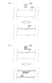
図9は、二つの異なるインク滴が記録媒体の同じ位置に着弾したときの浸透する様子を示した記録媒体の断面図である。図9(a)は、ある色のインクのドットのみが形成される場合であり、図9(b)は、図9(a)の後から他の色のインクのドットが重ねて形成される場合を示す。 FIG. 9 is a cross-sectional view of the recording medium showing how it penetrates when two different ink droplets land on the same position of the recording medium. FIG. 9A shows a case where only dots of ink of a certain color are formed, and FIG. 9B shows a case where dots of ink of other colors are overlapped after FIG. 9A. Show the case.
図9(a)において、記録ヘッドからインク滴901が吐出され、記録媒体902のまだインクが記録されていない領域(紙白)に着弾する。記録媒体902に着弾したインク滴901のうち、インクに含まれる溶剤が記録媒体内部に浸透し、インクに含まれる固形分である色材が記録媒体の表層に定着することで、ドット903が形成される。
In FIG. 9A,
図9(b)において、記録ヘッドから吐出されたインク滴904が、記録媒体902に形成されたドット903に重なるように着弾する。図のように、記録媒体上に既にインク滴が着弾してドットが形成されていると、同位置に後から着弾したインク滴904は既に形成されたドット903の奥深く浸透し、ドット905の位置まで浸透する。これは、先に着弾しているインクによって記録媒体の濡れ性が増し、浸透しやすい状態になっているためである。このように、後から着弾するインク滴が記録媒体の深部まで浸透することにより、記録媒体の表層には先に着弾したインク滴のドットが残り、その色が支配的に見えることになる。尚、本図では、浸透位置を簡略的に表現するためドット903とドット905が分離しているが、後から着弾したインク滴904の色材の一部も表層に残ることがある。
In FIG. 9B, the
また、紙面予備吐によるドットをより視認されづらくするためには、重なった2つのドットが横に広がらないように、予め、インクドットを凝集させる効果のある処理液を記録媒体に付与してもよい。また、先に着弾するインクと後から着弾するインクにお互いの色材が凝集するための成分を含ませてもよい。 Also, in order to make it more difficult to visually recognize the dots due to the preliminary ejection on the paper surface, it is possible to previously apply a treatment liquid having an effect of aggregating the ink dots to the recording medium so that the two overlapping dots do not spread sideways. Good. In addition, a component for aggregating each other's coloring material may be included in the ink landed first and the ink landed later.
また、後から着弾するインクの記録媒体に対する浸透性が、先に着弾するインクの記録媒体に対する浸透性よりも高い場合には、明度の低いインクが先に着弾し、明度の高いインクが後から着弾する形態であってもよい。先に着弾した明度の低いインクの色材が記録媒体の表層に定着する前に浸透性の高いインクが着弾すれば、浸透性の高いインクが記録媒体の深部に浸透する際に明度の低いインクの色材が一緒に引きこまれ、表層に残る色材の量が少なくなる。これにより、紙面予備吐により形成されるドットの視認性を下げることできる。 Further, when the penetrability of the ink landed later on the recording medium is higher than the penetrability of the ink landed first on the recording medium, the low-lightness ink landed first, and the high-lightness ink later It may be in the form of landing. If the ink with high penetrability landed before the coloring material of the low-brightness ink that landed first on the surface layer of the recording medium, the ink with low lightness when the penetrating ink penetrates deep into the recording medium. As a result, the amount of color material remaining on the surface layer is reduced. Thereby, the visibility of the dot formed by paper surface preliminary discharge can be lowered.
尚、本実施形態では、イエローの色材を含むイエローインクを明度の高いインクとして用い、ブラックの色材を含むブラックインクを明度の低いインクとして用いたが、この組み合わせに限られるものではない。明度の高いインクのドットと重ねることにより、単色でドットが形成された場合に比べて記録媒体上における明度が上がる効果を得られる組み合わせであれば、本発明は上記組み合わせに限られない。例えば、明度の低いインクとしてブラックインクを用いる替わりに、マゼンタの色材を含むマゼンタインクやシアンの色材を含むシアンインクを用いてもよい。また、色材が記録媒体のより深部に浸透するような効果を得られるものであれば、明度の高いインクとして色材を含まないクリアインクであってもよい。クリアインクを用いる形態では、CMYK全てのインクに対して重ねて吐出する形態であってもあってもよく、特定の色にのみ重ねて吐出する形態であってもよい。また、上記効果を得られる組み合わせであれば、明度の低いインクもしくは明度の高いインクのいずれかに、ライトシアン、ライトマゼンタ、グレイなどの色材濃度の低い淡インクを用いてもよく、レッド、グリーン、ブルーなどの特色インクを用いてもよい。 In this embodiment, yellow ink containing a yellow color material is used as an ink having a high lightness, and black ink containing a black color material is used as an ink having a low lightness. However, the present invention is not limited to this combination. The present invention is not limited to the above combinations as long as the effect of increasing the lightness on the recording medium as compared with the case where the dots are formed with a single color by overlapping the dots of ink with high lightness. For example, instead of using black ink as low-lightness ink, magenta ink containing magenta color material or cyan ink containing cyan color material may be used. Further, a clear ink that does not include a color material may be used as a high-lightness ink as long as an effect that allows the color material to penetrate deeper into the recording medium can be obtained. The form using the clear ink may be a form in which all the CMYK inks are ejected in a superimposed manner, or may be a form in which only a specific color is ejected. In addition, a light ink with a low colorant density such as light cyan, light magenta, or gray may be used for either a low-lightness ink or a high-lightness ink as long as the above effect is obtained. A special color ink such as blue may be used.
尚、本発明者らによる検証では、先にイエローインクを着弾させ、後にブラックインクを着弾させた場合、ブラックインクが記録媒体内部に浸透し、表層にはイエローインクが支配的に残った。ブラックインクのドット単体では、明度が低く、記録媒体の紙白領域との明度差が大きくなり、視認性が高くなってしまうが、イエローインクを重ねて打ち込むことで明度を上げ、紙白領域との明度差が小さくなり、ブラックのドットの視認性を下げることができる。均等色空間であるCIE−L*a*b*空間において明度を示すL値を測定した結果を以下に示す。L値が約90であるPB紙(キヤノン(株)製)に対してブラックインク単体を塗布した領域のL値は約3であったが、先にイエローインクを打ち込んだ後にブラックインクを打ちこんだ領域のL値は約6であり、明度が高くなることが確認できた。 In the verification by the present inventors, when the yellow ink was landed first and the black ink was landed later, the black ink penetrated into the recording medium, and the yellow ink remained predominantly on the surface layer. With black ink dots alone, the brightness is low, and the brightness difference from the paper white area of the recording medium increases and the visibility increases. The brightness difference between the two dots becomes small, and the visibility of black dots can be lowered. The results of measuring L values indicating lightness in the CIE-L * a * b * space, which is a uniform color space, are shown below. The L value of the area where the black ink was applied to PB paper (manufactured by Canon Inc.) having an L value of about 90 was about 3, but the black ink was applied after the yellow ink was applied first. The L value of the region was about 6, and it was confirmed that the brightness was high.
以上のように、明度の高いインクのドットと明度の低いインクのドットが重なるように紙面予備吐データを生成することにより、画像を記録すべき領域に予備吐出されるドットを視認されづらくすることができる。また、紙面予備吐を行うドットを重ねることにより、紙面予備吐により記録媒体上に形成されたドットが占める面積を少なくすることができるため、高品位な画像を形成することができる。 As described above, the preliminary ejection data on the paper surface is generated so that the dots of the high brightness ink and the low brightness ink overlap, thereby making it difficult to visually recognize the preliminary ejection dots in the area where the image is to be recorded. Can do. In addition, by overlapping the dots to be pre-discharged on the paper, the area occupied by the dots formed on the recording medium by the pre-discharge on the paper can be reduced, so that a high-quality image can be formed.
(第2実施形態)
上述の実施形態では、固定された記録ヘッドに対して記録媒体を搬送することにより相対移動を行う記録装置を例に挙げて説明したが、本実施形態では、記録ヘッドを記録媒体に対して走査させる、いわゆるシリアル記録を行う記録装置について説明する。
(Second Embodiment)
In the above-described embodiment, the recording apparatus that performs the relative movement by transporting the recording medium to the fixed recording head has been described as an example. However, in the present embodiment, the recording head is scanned with respect to the recording medium. A recording apparatus that performs so-called serial recording will be described.
図3は、本実施形態の記録ヘッドを説明するための図であり、図4は、記録ヘッドの走査と記録媒体の搬送を説明するための図である。図3及び図4において、y方向に記録媒体が搬送され、記録ヘッドはx方向に走査する。記録チップ300には、y方向に複数のノズルが配列し、ノズル列301はイエロー(Y)インク、ノズル列302はマゼンダ(M)インク、ノズル列303はシアン(C)インク、ノズル列304はブラック(K)インクにそれぞれ対応する。第1の実施形態と同様に、各ノズル列は2つのノズル列(例えば、ノズル列301−1及び301−2)で構成され、各列とも600dpiの解像度で配列されている。そして、隣り合うノズル列301−1及び301−2は、その配列ピッチがy方向において半ピッチ、すなわち、1/1200inchずれて配置されている。よって、隣接するノズル列士はy方向に1/1200inchずれた隣接するラスタを記録することになるので、y方向の記録解像度は1200dpiとなる。
FIG. 3 is a diagram for explaining the recording head of the present embodiment, and FIG. 4 is a diagram for explaining scanning of the recording head and conveyance of the recording medium. 3 and 4, the recording medium is conveyed in the y direction, and the recording head scans in the x direction. In the
図4において、記録チップ300を備える記録ヘッド401は、ノズルが配列するy方向と交差するx方向及び−x方向へ往復移動しながら、各ノズルからインク滴を吐出し、画像を記録する。記録媒体の搬送構成やキャッピング手段、制御系などは第1の実施形態と同じである。
In FIG. 4, a
図10は、本実施形態の紙面予備吐データのパターンを示す図である。図において四角で示した領域は1つの画素を示し、インク滴の吐出または非吐出を定める最小単位である。Y、M、C、Kは、各色のインクが吐出される画素を示している。第1の実施形態と同様に、イエローインクとブラックインクを同一画素に重ねて記録することで、紙面予備吐により形成されるドットが視認されづらくすることができる。 FIG. 10 is a diagram showing a pattern of the paper preliminary ejection data according to the present embodiment. In the figure, a region indicated by a square represents one pixel and is a minimum unit that determines whether or not ink droplets are ejected. Y, M, C, and K indicate pixels from which ink of each color is ejected. As in the first embodiment, by recording the yellow ink and the black ink on the same pixel, it is possible to make it difficult for the dots formed by the preliminary ejection on the paper to be visually recognized.
本実施形態のように、記録ヘッド401をシリアルに走査して画像を形成する記録装置においては、複数回の走査で画像を完成させるマルチパス記録方法を採用することが一般的である。マルチパス記録方法では、記録ヘッドの1回の走査で記録可能な画像データを、複数回の記録走査に対応したマスクパターンを用いて間引くことにより、各走査で記録すべきデータを生成する。各走査に対応するマスクパターンは補間関係にある。記録ヘッドの記録走査間では、記録ヘッドが記録可能な幅よりも短い幅の搬送量で記録媒体の搬送動作が行われる。例えば、2パスのマルチパス記録の場合、各記録主走査で適用するマスクパターンは画像データを約50%に間引き、搬送動作での搬送量は記録ヘッドが記録可能な幅の1/2である。このような記録走査と搬送動作を繰り返すことにより、主走査方向に延びる画素ライン(ラスタ)に配列されるドットは、異なる2つのノズルによって記録されることになる。よって、個々のノズルに多少のばらつきがあっても記録媒体上では1/2に分散されて記録されるので、マルチパス記録を行わない1パス記録の場合よりも、滑らかな画像を得ることが出来る。ここでは2パスのマルチパス記録について説明したが、マルチパス記録はそのマルチパス数(分割数)を更に多くするほど、より滑らかな画像を得ることが出来る。但し、記録走査および搬送動作の回数が増大するので、出力時間は余計に費やされる。出力時間を少しでも低減するために、記録ヘッドの往走査と復走査の両方でインクの吐出を行う双方向のマルチパス記録を行うことが多い。
In a recording apparatus that forms an image by serially scanning the
図11は、本実施形態で用いるマスクパターンの一例を示す図である。四角で示したここの領域は1つの画素を示し、ドットの記録の許容または非許容を定める最小単位であり、記録媒体上の1画素に対応する。黒く示した部分はその記録走査でインクの記録を許容する画素(記録許容画素)であり、白く示した部分はその記録走査でインクの記録を許容しない画素(非記録許容画素)である。ここでは図10に対応する15画素×30画素のマスクパターンを示している。マスクパターン1(1101)とマスクパターン2(1102)は互いに補完の関係にある2パス記録のマルチパス用のマスクパターンである。
FIG. 11 is a diagram illustrating an example of a mask pattern used in the present embodiment. The area here indicated by a square represents one pixel, which is the minimum unit that determines whether printing of dots is permitted or not, and corresponds to one pixel on the printing medium. The black portion is a pixel that allows ink recording by the recording scan (recording allowable pixel), and the white portion is a pixel that does not allow ink recording by the recording scan (non-recording allowable pixel). Here, a mask pattern of 15 pixels × 30 pixels corresponding to FIG. 10 is shown. Mask pattern 1 (1101) and mask pattern 2 (1102) are two-pass printing multi-pass mask patterns that are complementary to each other.
図12は、双方向の2パス記録を例に、各ノズル列に対してマスクパターンを適用し記録した際の紙面予備吐データを示す模式図である。図12(a)は2パス双方向のうち往方向の記録を示したもので、Yにはマスクパターン1を、M,C,Kにはマスクパターン2を適用している。図12(b)は2パス双方向のうち往方向の記録を図12(a)に重ねて記録したものを示しており、Yにはマスクパターン2を、M,C,Kにはマスクパターン1を適用している。図12(b)ではYとKのドットが同位置に形成されるが、2パス双方向印字のためそれぞれの着弾順序が異なることがある。図12(b)でYKと示している画素は、Yのインクが先に着弾し、後にKのインクが着弾した画素を示しており、KYと示している画素はその逆である。YKで示した画素のように、イエローインクが先に着弾し、後にブラックインクを同位置に着弾させた画素の明度を、ブラックインクのみが吐出された画素の明度よりも高くすることができる。また2つの紙面予備吐のドットを1つに重ねて形成することにより、記録媒体上で紙面予備吐が占める面積(被覆率)を少なくすることができるため、紙面予備吐の視認性をより低下させることができる。本実施形態においては、各色1列ずつのノズル列を備える記録ヘッドを用いたシリアルの双方向記録であるため、イエローインクの後にブラックインクが着弾する画素と、ブラックインクの後にイエローインクが着弾する画素の割合は1:1となる。尚、往走査と副走査とで同じ着弾順となるようにノズル列が配列した所謂ミラーヘッドを用いることにより、常に同じ順番でインクを重ねることが可能である。例えば、ノズル列が、Y、C、M、K、M、C、Kの順で並ぶ記録ヘッドであれば、往走査と副走査のいずれにおいてもイエローインクがブラックインクよりも先に着弾する。また、本実施形態では、紙面予備吐パターンを重ねる2つのインクを、2パス記録における異なるパスで打ち込むようなマスクパターンを適用したが、同じパスで重ねるようなマスクパターンを適用してもよい。また、パス間でのドットの重なりはマスクパターンによる分配に限らず、往走査用、復走査用の紙面予備吐データを生成して実現しても良い。また、同一パスで紙面予備吐によるドットを重ねる場合は、往方向で先に着弾するインクと復方向で先に着弾するインクは同じインクである必要は無く、往方向でYを先に着弾し、復方向でMを先に着弾するようなノズルの色順で実現してもよい。
FIG. 12 is a schematic diagram showing paper preliminary ejection data when printing is performed by applying a mask pattern to each nozzle row, taking bidirectional two-pass printing as an example. FIG. 12A shows the recording in the forward direction of the two-pass bidirectional, and the
(第3実施形態)
前述の実施形態では、ドットの視認性を下げるために2種類のインクが重なるように紙面予備吐データを生成する構成について説明したが、本発明者らの検証により、記録媒体の種類やインクの浸透特性によって得られる効果の程度が異なることが分かっている。例えば、普通紙のように記録媒体中への浸透が起きやすい記録媒体では、2色のインクを重ねることにより明度が上がる効果を得やすい傾向にある。一方、光沢紙やインクジェット専用紙は、インクの色材が記録媒体の受容層上部に残りやすいため、2色のインクを重ねることによる明度上昇効果が得られにくい場合がある。その場合には、図8のステップS805の紙面予備吐パターン生成時の処理を異ならせることが可能である。
(Third embodiment)
In the above-described embodiment, the configuration in which the paper preliminary ejection data is generated so that the two types of ink overlap in order to reduce the visibility of the dots has been described. It has been found that the degree of effect obtained depends on the penetration characteristics. For example, a recording medium such as plain paper that tends to penetrate into the recording medium tends to have an effect of increasing brightness by superimposing two colors of ink. On the other hand, glossy paper and ink jet exclusive paper tend to leave the ink color material on the receiving layer of the recording medium, and thus it may be difficult to obtain the effect of increasing the brightness by superimposing two colors of ink. In that case, it is possible to vary the processing at the time of generating the paper preliminary ejection pattern in step S805 of FIG.
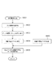
図13は、ステップS805の紙面予備吐データ生成処理における変形例である。ステップS1301では、画像を記録すべき記録媒体の種類を判定する。普通紙などの、インクが浸透しやすい記録媒体であると判定された場合には、ステップS1302に進み、イエローインクのドットとブラックインクのドットが重ねて形成されるように紙面予備吐データを生成する。インクジェット専用紙や光沢紙などの、インクが浸透しにくい記録媒体であると判定された場合には、ステップS1303に進み、イエローインクのドットを形成される画素とブラックインクのドットが形成される画素を異ならせ、重ならないようにする。 FIG. 13 is a modification of the paper preliminary ejection data generation processing in step S805. In step S1301, the type of recording medium on which an image is to be recorded is determined. If it is determined that the recording medium is easy to permeate ink, such as plain paper, the process advances to step S1302 to generate pre-discharge data on the paper so that the yellow ink dots and the black ink dots are formed in an overlapping manner. To do. If it is determined that the recording medium is difficult to permeate ink, such as ink-jet paper or glossy paper, the process proceeds to step S1303, where pixels for forming yellow ink dots and pixels for forming black ink dots are processed. Make sure they are different and do not overlap.
このように、ドットを重ねて形成することにより視認性が下がる効果は記録媒体の種類に応じて異なるため、上記構成により記録媒体の種類に応じて適切に紙面予備吐データを生成することができる。 As described above, the effect of lowering the visibility due to the dot formation is different depending on the type of the recording medium. Therefore, the above-described configuration can appropriately generate the paper preliminary ejection data according to the type of the recording medium. .
また、ドットを重ねて形成する際には、必ずしも同一画素に重ねなくてもよい。記録解像度と紙面上に形成されるドットのサイズに応じて適宜決定すればよい。例えば、記録媒体上に仮想的に設定した1画素のサイズに対して、実際に形成されるドットサイズが大きい場合には、隣り合う2つの画素に明度の高いインクと明度の低いインクを吐出すれば重なりを作ることができる。また、予備吐出による明度の高いインクのドットと明度の低いインクのドットを全て重ねなくてもよく、少なくとも一部が重なるようにすることで、視認されづらくする効果を得ることは可能である。 Further, when dots are formed in an overlapping manner, it is not always necessary to overlap the same pixel. What is necessary is just to determine suitably according to recording resolution and the size of the dot formed on a paper surface. For example, when the dot size actually formed is larger than the size of one pixel virtually set on the recording medium, high-lightness ink and low-lightness ink are ejected to two adjacent pixels. You can make an overlap. In addition, it is not necessary to overlap all the dots of ink with high lightness and ink with low lightness by preliminary ejection, and it is possible to obtain an effect of making it difficult to be visually recognized by at least partially overlapping.
100 記録チップ
101〜104 ノズル列
201 記録ヘッド
202 記録媒体
DESCRIPTION OF
Claims (14)
前記記録媒体が第1の記録媒体である場合には、予備吐出により前記所定領域に形成される前記第1インクのドットが、予備吐出により前記所定領域に形成される前記第2インクのドットと重なり、且つ、予備吐出により前記所定領域に形成される前記第3インクのドットと重ならないように前記予備吐出を行い、前記記録媒体が前記第1の記録媒体よりもインクが浸透しにくい第2の記録媒体である場合には、予備吐出により前記所定領域に形成される前記第1インクのドットが、予備吐出により前記所定領域に形成される前記第2インクのドットと重ならないように前記予備吐出を行うことを特徴とする記録方法。 A recording head that discharges a first ink, a second ink having a higher brightness than the first ink, and a third ink having a higher brightness than the first ink and a lower brightness than the second ink is used. When an image is recorded on the recording medium, preliminary ejection that does not contribute to the recording of the image is performed in order to maintain the ejection state of the ink from the recording head with respect to a predetermined region where the image is formed. A recording method,
When the recording medium is a first recording medium, the dots of the first ink formed in the predetermined area by preliminary ejection are the dots of the second ink formed in the predetermined area by preliminary ejection. The preliminary ejection is performed so that the dots overlap and do not overlap the dots of the third ink formed in the predetermined area by the preliminary ejection, and the recording medium is less likely to permeate the ink than the first recording medium. The first ink dots formed in the predetermined area by the preliminary discharge do not overlap the dots of the second ink formed in the predetermined area by the preliminary discharge. A recording method comprising discharging .
前記記録媒体が第1の記録媒体である場合には、予備吐出により前記所定領域に形成される前記第1インクのドットが、予備吐出により前記所定領域に形成される前記第2インクのドットと重なり、且つ、予備吐出により前記所定領域に形成される前記第3インクのドットと重ならないように前記予備吐出を行い、前記記録媒体が前記第1の記録媒体よりもインクが浸透しにくい第2の記録媒体である場合には、予備吐出により前記所定領域に形成される前記第1インクのドットが、予備吐出により前記所定領域に形成される前記第2インクのドットと重ならないように前記予備吐出を行うことを特徴とする記録装置。 A recording head that discharges a first ink, a second ink having a higher brightness than the first ink, and a third ink having a higher brightness than the first ink and a lower brightness than the second ink is used. When an image is recorded on the recording medium, preliminary ejection that does not contribute to the recording of the image is performed in order to maintain the ejection state of the ink from the recording head with respect to a predetermined region where the image is formed. A recording device,
When the recording medium is a first recording medium, the dots of the first ink formed in the predetermined area by preliminary ejection are the dots of the second ink formed in the predetermined area by preliminary ejection. The preliminary ejection is performed so that the dots overlap and do not overlap the dots of the third ink formed in the predetermined area by the preliminary ejection, and the recording medium is less likely to permeate the ink than the first recording medium. The first ink dots formed in the predetermined area by the preliminary discharge do not overlap the dots of the second ink formed in the predetermined area by the preliminary discharge. A recording apparatus that performs ejection .
Priority Applications (2)
| Application Number | Priority Date | Filing Date | Title |
|---|---|---|---|
| JP2014094815A JP6362083B2 (en) | 2014-05-01 | 2014-05-01 | Recording method, recording apparatus, image processing apparatus, and image processing method |
| US14/699,108 US9399355B2 (en) | 2014-05-01 | 2015-04-29 | Printing method, printing apparatus, and computer-readable storage medium |
Applications Claiming Priority (1)
| Application Number | Priority Date | Filing Date | Title |
|---|---|---|---|
| JP2014094815A JP6362083B2 (en) | 2014-05-01 | 2014-05-01 | Recording method, recording apparatus, image processing apparatus, and image processing method |
Publications (3)
| Publication Number | Publication Date |
|---|---|
| JP2015212031A JP2015212031A (en) | 2015-11-26 |
| JP2015212031A5 JP2015212031A5 (en) | 2017-08-31 |
| JP6362083B2 true JP6362083B2 (en) | 2018-07-25 |
Family
ID=54354600
Family Applications (1)
| Application Number | Title | Priority Date | Filing Date |
|---|---|---|---|
| JP2014094815A Active JP6362083B2 (en) | 2014-05-01 | 2014-05-01 | Recording method, recording apparatus, image processing apparatus, and image processing method |
Country Status (2)
| Country | Link |
|---|---|
| US (1) | US9399355B2 (en) |
| JP (1) | JP6362083B2 (en) |
Families Citing this family (3)
| Publication number | Priority date | Publication date | Assignee | Title |
|---|---|---|---|---|
| JP7196443B2 (en) * | 2018-07-17 | 2022-12-27 | 京セラドキュメントソリューションズ株式会社 | Inkjet recording device and flushing method |
| JP7136707B2 (en) * | 2019-01-11 | 2022-09-13 | 株式会社ミマキエンジニアリング | Printing device and printing method |
| JP7387995B2 (en) | 2019-03-27 | 2023-11-29 | ブラザー工業株式会社 | image recording device |
Family Cites Families (6)
| Publication number | Priority date | Publication date | Assignee | Title |
|---|---|---|---|---|
| US5903288A (en) | 1996-02-14 | 1999-05-11 | Seiko Epson Corporation | Apparatus and method for flushing ink-jet recording heads without suspension of printing |
| JP2006168209A (en) * | 2004-12-16 | 2006-06-29 | Canon Inc | Inkjet recording device |
| JP4182103B2 (en) | 2005-12-09 | 2008-11-19 | キヤノン株式会社 | Ink jet recording apparatus and recording method |
| JP2011213059A (en) * | 2010-04-01 | 2011-10-27 | Seiko Epson Corp | Inkjet recording method |
| JP5811557B2 (en) * | 2011-03-18 | 2015-11-11 | 株式会社リコー | Image forming apparatus and program |
| US8506046B2 (en) * | 2011-09-23 | 2013-08-13 | Infoprint Solutions Company Llc | Inkjet nozzle flushing mechanism |
-
2014
- 2014-05-01 JP JP2014094815A patent/JP6362083B2/en active Active
-
2015
- 2015-04-29 US US14/699,108 patent/US9399355B2/en active Active
Also Published As
| Publication number | Publication date |
|---|---|
| US9399355B2 (en) | 2016-07-26 |
| US20150314610A1 (en) | 2015-11-05 |
| JP2015212031A (en) | 2015-11-26 |
Similar Documents
| Publication | Publication Date | Title |
|---|---|---|
| JP4164305B2 (en) | Inkjet recording method and inkjet recording apparatus | |
| US7296868B2 (en) | Ink jet printing system | |
| JP5473420B2 (en) | DATA GENERATION DEVICE, INKJET RECORDING DEVICE, PROGRAM, AND DATA GENERATION METHOD | |
| JP6415080B2 (en) | Image processing apparatus, image processing method, recording apparatus, and program | |
| JP2006062333A (en) | Ink-jet recording apparatus and ink-jet recording method | |
| JP5311980B2 (en) | Inkjet recording device | |
| JP6362083B2 (en) | Recording method, recording apparatus, image processing apparatus, and image processing method | |
| JP6448346B2 (en) | Inkjet recording apparatus and inkjet recording method | |
| JP2010120254A (en) | Printer and method of detecting non-ejecting nozzle | |
| JP5698505B2 (en) | Inkjet recording device | |
| JP4990833B2 (en) | Non-ejection detection method, non-ejection detection device, and inkjet recording apparatus | |
| JP2006168073A (en) | Inkjet recording system | |
| JP2011126175A (en) | Inkjet recording device and method, and data generating apparatus, and program | |
| JP4701596B2 (en) | Inkjet recording apparatus and inkjet recording method | |
| JP5084159B2 (en) | Inkjet recording apparatus, inkjet recording method, and program | |
| JP2011104788A (en) | Printing apparatus and printing method | |
| JP2007118444A (en) | Inkjet recording method | |
| JP6021345B2 (en) | Image recording apparatus and image recording method | |
| JP2015143012A (en) | Inkjet recording device and image processing device | |
| JP2005161630A (en) | Inkjet recording system and inkjet recording method | |
| JP2016175191A (en) | Image formation apparatus, image formation method and program | |
| JP2004195704A (en) | Recording method and recording device | |
| JP2021094704A (en) | Liquid discharge device and method, and program | |
| JP5717346B2 (en) | Image processing apparatus, image processing method, recording apparatus, and recording method | |
| JP7439595B2 (en) | Recording device and recording method |
Legal Events
| Date | Code | Title | Description |
|---|---|---|---|
| A621 | Written request for application examination |
Free format text: JAPANESE INTERMEDIATE CODE: A621 Effective date: 20170428 |
|
| A521 | Request for written amendment filed |
Free format text: JAPANESE INTERMEDIATE CODE: A523 Effective date: 20170719 |
|
| A977 | Report on retrieval |
Free format text: JAPANESE INTERMEDIATE CODE: A971007 Effective date: 20180129 |
|
| A131 | Notification of reasons for refusal |
Free format text: JAPANESE INTERMEDIATE CODE: A131 Effective date: 20180206 |
|
| A521 | Request for written amendment filed |
Free format text: JAPANESE INTERMEDIATE CODE: A523 Effective date: 20180405 |
|
| TRDD | Decision of grant or rejection written | ||
| A01 | Written decision to grant a patent or to grant a registration (utility model) |
Free format text: JAPANESE INTERMEDIATE CODE: A01 Effective date: 20180522 |
|
| A61 | First payment of annual fees (during grant procedure) |
Free format text: JAPANESE INTERMEDIATE CODE: A61 Effective date: 20180619 |
|
| R151 | Written notification of patent or utility model registration |
Ref document number: 6362083 Country of ref document: JP Free format text: JAPANESE INTERMEDIATE CODE: R151 |