JP6362082B2 - Sheet processing apparatus and image forming apparatus - Google Patents

Sheet processing apparatus and image forming apparatus Download PDF

Info

Publication number
JP6362082B2
JP6362082B2 JP2014093864A JP2014093864A JP6362082B2 JP 6362082 B2 JP6362082 B2 JP 6362082B2 JP 2014093864 A JP2014093864 A JP 2014093864A JP 2014093864 A JP2014093864 A JP 2014093864A JP 6362082 B2 JP6362082 B2 JP 6362082B2
Authority
JP
Japan
Prior art keywords
sheet
binding
sheet bundle
unit
stacking
Prior art date
Legal status (The legal status is an assumption and is not a legal conclusion. Google has not performed a legal analysis and makes no representation as to the accuracy of the status listed.)
Expired - Fee Related
Application number
JP2014093864A
Other languages
Japanese (ja)
Other versions
JP2015209334A (en
JP2015209334A5 (en
Inventor
秀樹 ▲櫛▼田
秀樹 ▲櫛▼田
渡邊 潔
潔 渡邊
直人 徳間
直人 徳間
俊行 岩田
俊行 岩田
明人 関川
明人 関川
Current Assignee (The listed assignees may be inaccurate. Google has not performed a legal analysis and makes no representation or warranty as to the accuracy of the list.)
Canon Inc
Original Assignee
Canon Inc
Priority date (The priority date is an assumption and is not a legal conclusion. Google has not performed a legal analysis and makes no representation as to the accuracy of the date listed.)
Filing date
Publication date
Application filed by Canon Inc filed Critical Canon Inc
Priority to JP2014093864A priority Critical patent/JP6362082B2/en
Priority to US14/693,167 priority patent/US9833967B2/en
Publication of JP2015209334A publication Critical patent/JP2015209334A/en
Publication of JP2015209334A5 publication Critical patent/JP2015209334A5/ja
Application granted granted Critical
Publication of JP6362082B2 publication Critical patent/JP6362082B2/en
Expired - Fee Related legal-status Critical Current
Anticipated expiration legal-status Critical

Links

Images

Classifications

    • BPERFORMING OPERATIONS; TRANSPORTING
    • B31MAKING ARTICLES OF PAPER, CARDBOARD OR MATERIAL WORKED IN A MANNER ANALOGOUS TO PAPER; WORKING PAPER, CARDBOARD OR MATERIAL WORKED IN A MANNER ANALOGOUS TO PAPER
    • B31FMECHANICAL WORKING OR DEFORMATION OF PAPER, CARDBOARD OR MATERIAL WORKED IN A MANNER ANALOGOUS TO PAPER
    • B31F5/00Attaching together sheets, strips or webs; Reinforcing edges
    • B31F5/02Attaching together sheets, strips or webs; Reinforcing edges by crimping or slotting or perforating
    • BPERFORMING OPERATIONS; TRANSPORTING
    • B42BOOKBINDING; ALBUMS; FILES; SPECIAL PRINTED MATTER
    • B42BPERMANENTLY ATTACHING TOGETHER SHEETS, QUIRES OR SIGNATURES OR PERMANENTLY ATTACHING OBJECTS THERETO
    • B42B5/00Permanently attaching together sheets, quires or signatures otherwise than by stitching
    • BPERFORMING OPERATIONS; TRANSPORTING
    • B31MAKING ARTICLES OF PAPER, CARDBOARD OR MATERIAL WORKED IN A MANNER ANALOGOUS TO PAPER; WORKING PAPER, CARDBOARD OR MATERIAL WORKED IN A MANNER ANALOGOUS TO PAPER
    • B31FMECHANICAL WORKING OR DEFORMATION OF PAPER, CARDBOARD OR MATERIAL WORKED IN A MANNER ANALOGOUS TO PAPER
    • B31F1/00Mechanical deformation without removing material, e.g. in combination with laminating
    • BPERFORMING OPERATIONS; TRANSPORTING
    • B42BOOKBINDING; ALBUMS; FILES; SPECIAL PRINTED MATTER
    • B42FSHEETS TEMPORARILY ATTACHED TOGETHER; FILING APPLIANCES; FILE CARDS; INDEXING
    • B42F3/00Sheets temporarily attached together involving perforations; Means therefor; Sheet details therefor
    • BPERFORMING OPERATIONS; TRANSPORTING
    • B65CONVEYING; PACKING; STORING; HANDLING THIN OR FILAMENTARY MATERIAL
    • B65HHANDLING THIN OR FILAMENTARY MATERIAL, e.g. SHEETS, WEBS, CABLES
    • B65H31/00Pile receivers
    • B65H31/34Apparatus for squaring-up piled articles
    • BPERFORMING OPERATIONS; TRANSPORTING
    • B65CONVEYING; PACKING; STORING; HANDLING THIN OR FILAMENTARY MATERIAL
    • B65HHANDLING THIN OR FILAMENTARY MATERIAL, e.g. SHEETS, WEBS, CABLES
    • B65H37/00Article or web delivery apparatus incorporating devices for performing specified auxiliary operations
    • B65H37/04Article or web delivery apparatus incorporating devices for performing specified auxiliary operations for securing together articles or webs, e.g. by adhesive, stitching or stapling
    • BPERFORMING OPERATIONS; TRANSPORTING
    • B65CONVEYING; PACKING; STORING; HANDLING THIN OR FILAMENTARY MATERIAL
    • B65HHANDLING THIN OR FILAMENTARY MATERIAL, e.g. SHEETS, WEBS, CABLES
    • B65H2301/00Handling processes for sheets or webs
    • B65H2301/50Auxiliary process performed during handling process
    • B65H2301/51Modifying a characteristic of handled material
    • B65H2301/516Securing handled material to another material
    • B65H2301/5161Binding processes
    • B65H2301/51616Binding processes involving simultaneous deformation of parts of the material to be bound
    • BPERFORMING OPERATIONS; TRANSPORTING
    • B65CONVEYING; PACKING; STORING; HANDLING THIN OR FILAMENTARY MATERIAL
    • B65HHANDLING THIN OR FILAMENTARY MATERIAL, e.g. SHEETS, WEBS, CABLES
    • B65H2801/00Application field
    • B65H2801/24Post -processing devices
    • B65H2801/27Devices located downstream of office-type machines

Description

本発明は、シート束の所定位置を綴じ処理するシート処理装置及びこれを備えた画像形成装置に関する。   The present invention relates to a sheet processing apparatus that binds a predetermined position of a sheet bundle and an image forming apparatus including the sheet processing apparatus.

従来、画像形成されたシートを綴じ処理し、所定のトレイ上にシート束の状態で積載処理するシート処理装置として、特許文献1のように針を使用しないで、複数のシートを綴じる技術が開示されている。具体的には、切削により半抜き舌状片とスリットとをシートに形成し、半抜き舌状片の端部をスリット内に挿入する。これにより積載されたシート同士を締結するものである。   2. Description of the Related Art Conventionally, as a sheet processing apparatus that binds an image-formed sheet and stacks the sheets on a predetermined tray in a sheet bundle state, a technique for binding a plurality of sheets without using a needle as disclosed in Patent Document 1 is disclosed. Has been. Specifically, the half-cut tongue piece and the slit are formed in the sheet by cutting, and the end of the half-cut tongue piece is inserted into the slit. As a result, the stacked sheets are fastened together.

図21を用いて特許文献1に記載されたシート処理装置の綴じ動作について説明する。図示しない画像形成装置から排出されたシートはパドル37の回転動作によってコンパイル積載部35上を一枚づつエンドガイド35bの方向に送られて積載されてシート束を形成する。コンパイル積載部35のエンドガイド35bにはステイプル綴じ部45と、針無し綴じ部50とが図示しないジョイント部材を介して並設されている。そして、コンパイル積載部35上に積載されたシート束に対してステイプル綴じ部45と、針無し綴じ部50との何れかにより綴じ処理が施される。   The binding operation of the sheet processing apparatus described in Patent Document 1 will be described with reference to FIG. Sheets discharged from an image forming apparatus (not shown) are fed one by one on the compilation stacking unit 35 in the direction of the end guide 35b by the rotational operation of the paddle 37 to form a sheet bundle. A staple binding portion 45 and a needleless binding portion 50 are juxtaposed on the end guide 35b of the compile stacking portion 35 via a joint member (not shown). Then, the binding process is performed on the sheet bundle stacked on the compilation stacking unit 35 by either the staple binding unit 45 or the stapleless binding unit 50.

ステイプル綴じ部45と、針無し綴じ部50との何れかにより綴じ処理されたシート束はイジェクトロール39によって搬送されて図示しない積載部上に排出される。従って、ステイプル綴じ部45によるステイプル綴じと、針無し綴じ部50による針無し綴じとの異なる複数の綴じ方法によりシート束を綴じることが可能であり、保守作業の少ない針無し綴じを備えたシート処理装置を提供することが出来るものである。   The sheet bundle that is bound by either the staple binding unit 45 or the stapleless binding unit 50 is conveyed by the eject roll 39 and discharged onto a stacking unit (not shown). Therefore, it is possible to bind a sheet bundle by a plurality of binding methods different from the staple binding by the staple binding unit 45 and the stapleless binding by the needleless binding unit 50, and the sheet processing including the stapleless binding with less maintenance work. A device can be provided.

特許第5056918号公報Japanese Patent No. 5056918

近年、シート処理装置として、排出口側からユーザによってシート束を挿し込み、シート処理装置内に備えるシート処理部によって、マニュアル操作により、例えば綴じ処理等のシート処理を実行出来る装置が提案されている。   2. Description of the Related Art In recent years, as a sheet processing apparatus, an apparatus has been proposed in which a sheet bundle is inserted by a user from the discharge port side, and sheet processing such as binding processing can be performed manually by a sheet processing unit provided in the sheet processing apparatus. .

特許文献1のようにシート束の半抜き舌状片の先端部をスリットに挿入して複数のシートをシート束として綴るような針無し綴じ方式がある。その場合、図22に示すように、半抜き舌状片1pの先端部1p1を折り返してスリット1sに挿入する。シート束1nのシート面1n1から突出した挿し込み綴じ部1rを含む綴じ処理後のシート束1nの厚みtaは、綴じ処理前のシート束1nの厚みtbの略三倍程度に部分的に盛り上がった形状になる。   As disclosed in Patent Document 1, there is a needleless binding method in which a plurality of sheets are bound as a sheet bundle by inserting the tip end portion of the half-blanked tongue-shaped piece of the sheet bundle into a slit. In that case, as shown in FIG. 22, the front end portion 1p1 of the half-cut tongue-like piece 1p is folded back and inserted into the slit 1s. The thickness ta of the sheet bundle 1n after the binding process including the insertion binding portion 1r protruding from the sheet surface 1n1 of the sheet bundle 1n partially rises to about three times the thickness tb of the sheet bundle 1n before the binding process. Become a shape.

特許文献1の他にハンドクリンチ方式の切り込み挿入型の針無し綴じ機構は広く開示されている。しかし、これらの針無し綴じ機構は、綴じ処理出来るシート枚数に制限がある。例えば、ユーザによって過剰な枚数のシートが挿入された場合、針無し綴じ機構がロックして装置の破損につながる恐れがある。   In addition to Patent Document 1, a hand clinching type notch insertion type needleless binding mechanism is widely disclosed. However, these needleless binding mechanisms are limited in the number of sheets that can be bound. For example, when an excessive number of sheets are inserted by the user, the stapleless binding mechanism may be locked, resulting in damage to the apparatus.

このためマニュアルで操作されるような装置の場合は、ユーザによって過剰な枚数のシートが挿入されないように、予めクリンチの間口間隔、或いは、入口部のガイド部材をシート処理可能な枚数が挿入出来るように制限しておく必要がある。   For this reason, in the case of an apparatus that is operated manually, the clinch gap interval or the number of sheets capable of sheet processing can be inserted in advance so that the user does not insert an excessive number of sheets. It is necessary to limit to.

特許文献1では、画像形成枚数を制御し、コンパイル積載部35に積載されるシートの枚数を制御することが可能なためクリンチの間口間隔は、綴じ処理後のシート束1nの厚さに対応した間隔に設定しておけば良い。   In Patent Document 1, since it is possible to control the number of images to be formed and to control the number of sheets stacked on the compile stacking unit 35, the gap between the clinch corresponds to the thickness of the sheet bundle 1n after the binding process. Set to an interval.

しかしながら、シート処理装置に針無し綴じ機構を備え、画像形成装置から排出されるシートを直接積載しながら処理するオート綴じ処理と、ユーザ挿入によるマニュアル綴じ処理の双方を実施可能なシート処理装置を実現させたい場合がある。その場合、トレイに排出するオート綴じ処理と、装置手前方向からユーザがシート束を挿入するマニュアル綴じ処理とで、クリンチの間口からシート束が抜き取られる方向が異なる。   However, the sheet processing apparatus has a needleless binding mechanism, and realizes a sheet processing apparatus capable of performing both automatic binding processing for directly stacking sheets discharged from the image forming apparatus and manual binding processing by user insertion. Sometimes you want to In that case, the direction in which the sheet bundle is extracted from the front edge of the clinch differs between the automatic binding process for discharging to the tray and the manual binding process in which the user inserts the sheet bundle from the front side of the apparatus.

従って、特許文献1のようなシート処理装置においてマニュアルで多数のシート束1nの針無し綴じ処理を実施する。すると、ユーザによって過剰な枚数のシートが挿入され、綴じ機構部がロックして装置の破損につながる可能性がある。単純にクリンチの間口間隔を狭くすると、綴じ処理後、ユーザによってシート束を抜き取る際に、図22に示す挿し込み綴じ部1rがクリンチに引っ掛かり易くなり、操作性が悪い。また、綴じシート束1nの破損につながる可能性もあることから操作性向上と破損防止等の品質保証の両立を図ることが困難であった。   Accordingly, a staple-free binding process for a large number of sheet bundles 1n is manually performed in a sheet processing apparatus such as that disclosed in Patent Document 1. Then, an excessive number of sheets may be inserted by the user, and the binding mechanism may be locked, resulting in damage to the apparatus. If the gap between the clinch is simply narrowed, the insertion binding portion 1r shown in FIG. 22 is easily caught by the clinch when the user pulls out the sheet bundle after the binding process, and the operability is poor. Further, since there is a possibility that the binding sheet bundle 1n may be damaged, it is difficult to achieve both operability improvement and quality assurance such as damage prevention.

本発明は前記課題を解決するものであり、その目的とするところは、操作性向上と破損防止等の品質保証の両立を図ることが出来るシート処理装置を提供するものである。   The present invention solves the above-mentioned problems, and an object of the present invention is to provide a sheet processing apparatus capable of achieving both operability improvement and quality assurance such as damage prevention.

前記目的を達成するための本発明に係るシート処理装置の代表的な構成は、搬送手段によって搬送されたシートが積載される第1積載手段と、前記第1積載手段のシートを整合する整合手段と、前記第1積載手段に積載されたシート束に対して一部がシートと連結した状態で切削された半抜き舌状片と、貫通穴からなるスリットとを各シートに形成し、前記シート束の各半抜き舌状片の先端部を前記シート束の各スリットに挿入する処理を処理位置において施すことによって前記シート束の端部を綴じる綴じ手段と、前記綴じ手段により綴じられたシート束が積載される第2積載手段と、を有し、前記搬送手段によって搬送されてきた、前記第1積載手段に積載されたシート束を、前記綴じ手段により綴じる第1綴じ動作と、前記搬送手段によるシート搬送方向とは異なる方向からマニュアルで前記第1積載手段の上に載置されたシート束を、前記綴じ手段により綴じる第2綴じ動作と、を行ない、前記綴じ手段の少なくとも一方のガイド面に、前記処理位置から前記第2積載手段へ向かう方向に延伸された第1の凹部と、前記処理位置から前記第1の凹部の延伸方向とは異なる方向に延伸された第2の凹部と、が設けられたことを特徴とする。 In order to achieve the above object, a typical configuration of a sheet processing apparatus according to the present invention includes a first stacking unit on which sheets conveyed by the conveying unit are stacked, and an alignment unit that aligns the sheets of the first stacking unit. Each sheet is formed with a half-cut tongue-like piece cut in a state where a part of the sheet bundle stacked on the first stacking unit is connected to the sheet, and a slit made of a through hole. A binding means for binding the end of the sheet bundle by performing processing at the processing position to insert the tip of each half-cut tongue-like piece of the bundle into each slit of the sheet bundle, and the sheet bundle bound by the binding means A first stacking operation for binding the sheet bundle loaded on the first stacking unit, which has been transported by the transporting unit, by the binding unit, and the transporting unit. In A second binding operation for manually binding the sheet bundle placed on the first stacking means from a direction different from the sheet conveying direction by the binding means, and at least one guide surface of the binding means , the first recess and the second recess extends from the processing position to the direction towards that is different from the extending direction of the first recess which is oriented in the direction towards the second stacking unit from the processing position And is provided.

上記構成によれば、綴じ手段によるオート綴じと、マニュアル綴じとの双方の処理が選択可能で、操作性向上と破損防止等の品質保証の両立を図ることが出来る。   According to the above configuration, it is possible to select both automatic binding by the binding means and manual binding, and it is possible to achieve both operability improvement and quality assurance such as damage prevention.

本発明に係るシート処理装置を備えた画像形成装置の構成を示す断面説明図である。1 is an explanatory cross-sectional view illustrating a configuration of an image forming apparatus including a sheet processing apparatus according to the present invention. 画像形成装置の制御系の構成を示すブロック図である。2 is a block diagram illustrating a configuration of a control system of the image forming apparatus. FIG. シ―ト処理装置となるフィニッシャの構成を示す断面説明図である。FIG. 5 is a cross-sectional explanatory view showing a configuration of a finisher serving as a sheet processing apparatus. フィニッシャの制御系の構成を示すブロック図である。It is a block diagram which shows the structure of the control system of a finisher. フィニッシャに設けられた中間積載手段の構成を示す断面説明図である。It is sectional explanatory drawing which shows the structure of the intermediate | middle stacking means provided in the finisher. 中間積載手段に設けられた整合手段の構成を示す平面説明図である。It is a plane explanatory drawing which shows the structure of the alignment means provided in the intermediate stacking means. 中間積載手段の構成を示す斜視説明図である。It is a perspective explanatory view showing the configuration of the intermediate stacking means. 針無し綴じ部の構成を示す斜視説明図である。It is an isometric view explanatory drawing which shows the structure of a needleless binding part. (a),(b)は針無し綴じ部の構成を示す右側面図及び正面図である。(A), (b) is the right view and front view which show the structure of a needleless binding part. (a),(b)は針無し綴じ部の動作を説明する正面説明図である。(A), (b) is front explanatory drawing explaining operation | movement of a needleless binding part. (a),(b)は針無し綴じ部の動作を説明する正面説明図である。(A), (b) is front explanatory drawing explaining operation | movement of a needleless binding part. 針無し綴じ処理後のシート束の状態を示す斜視説明図である。It is a perspective explanatory view showing a state of a sheet bundle after the stapleless binding process. (a),(b)はオート綴じノンソート時におけるシートの流れを説明する断面説明図である。(A), (b) is sectional explanatory drawing explaining the flow of the sheet | seat at the time of automatic binding non-sorting. オート綴じノンソート時におけるシートの流れを説明する正面説明図である。FIG. 10 is a front explanatory view illustrating the flow of sheets during automatic binding non-sorting. (a)はオート綴じソート時におけるシートの流れを説明する正面説明図である。(b)は積載手段上に交互にずらされた状態で積載されたシート束の様子を示す正面説明図である。(A) is a front explanatory drawing explaining the flow of a sheet at the time of automatic binding sorting. (B) is a front explanatory view showing the state of a sheet bundle stacked in a state of being alternately shifted on the stacking means. マニュアル綴じ時におけるフィニッシャの動作を説明する平面説明図である。It is a plane explanatory view explaining the operation of the finisher at the time of manual binding. マニュアル綴じ時におけるフィニッシャの動作を説明する斜視説明図である。It is a perspective explanatory view explaining the operation of the finisher at the time of manual binding. 綴じ処理制御を説明するフローチャートである。It is a flowchart explaining binding process control. 他の綴じ処理制御を説明するフローチャートである。It is a flowchart explaining other binding process control. (a),(b)は他の針無し綴じ部の構成を示す斜視説明図である。(A), (b) is a perspective explanatory drawing which shows the structure of another needleless binding part. 特許文献1の針無し綴じ部のシート束の状態を示す平面説明図である。10 is a plan explanatory view showing a state of a sheet bundle of a stapleless binding portion of Patent Document 1. FIG. 針無し綴じ処理後のシート束の状態を示す断面説明図である。FIG. 6 is a cross-sectional explanatory diagram illustrating a state of a sheet bundle after a stapleless binding process.

図により本発明に係るシート処理装置を備えた画像形成装置の一実施形態を具体的に説明する。図1は本発明に係るシート処理装置を備えた画像形成装置の構成を示す断面説明図である。図1において、502は画像形成装置、550は画像形成装置502本体の上部に設けられた原稿読み取り部(イメージリーダ)、551は複数の原稿を自動的に読み取るための原稿搬送装置である。   An embodiment of an image forming apparatus provided with a sheet processing apparatus according to the present invention will be specifically described with reference to the drawings. FIG. 1 is an explanatory cross-sectional view showing a configuration of an image forming apparatus provided with a sheet processing apparatus according to the present invention. In FIG. 1, reference numeral 502 denotes an image forming apparatus, 550 denotes a document reading unit (image reader) provided at the upper part of the main body of the image forming apparatus 502, and 551 denotes a document conveying device for automatically reading a plurality of documents.

<画像形成装置>
画像形成装置502は、トナー画像を形成するための記録材となるシート1を積載する給送カセット909a,909bを有する。更に、電子写真画像形成プロセス手段を用いてシート1上にトナー画像を形成する画像形成手段となる画像形成部503を有する。更に、シート1に形成されたトナー画像を定着させる定着手段となる定着装置904等を備えている。
<Image forming apparatus>
The image forming apparatus 502 includes feeding cassettes 909a and 909b on which sheets 1 serving as recording materials for forming toner images are stacked. Further, an image forming unit 503 serving as an image forming unit that forms a toner image on the sheet 1 using the electrophotographic image forming process unit is provided. Further, a fixing device 904 serving as a fixing unit for fixing the toner image formed on the sheet 1 is provided.

また、画像形成装置502本体の上面にはユーザが画像形成装置502に対して各種入力や設定を行うための操作部501が設けられている。また、画像形成装置502本体の側方には、シート処理装置となるフィニッシャ100が接続されている。尚、960は画像形成装置502及びシート処理装置となるフィニッシャ100の制御を司る制御手段となる制御部である。   An operation unit 501 is provided on the upper surface of the main body of the image forming apparatus 502 for the user to make various inputs and settings to the image forming apparatus 502. A finisher 100 serving as a sheet processing apparatus is connected to the side of the image forming apparatus 502 main body. Reference numeral 960 denotes a control unit serving as a control unit that controls the image forming apparatus 502 and the finisher 100 serving as a sheet processing apparatus.

本実施形態の画像形成装置502において、図示しない原稿の画像をシート1に形成する際には、先ず、原稿搬送装置551により搬送された原稿の画像を原稿読み取り部550に設けられた画像読取手段となるイメージセンサ550aにより読み取る。その後、読み取られたデジタルデータを露光手段となる露光装置504に入力し、該露光装置504は、このデジタルデータに応じた光を画像形成部503に設けられた像担持体となる各感光ドラム914a〜914dの表面に照射する。尚、説明の都合上、各感光ドラム914a〜914dを代表して単に感光ドラム914という場合もある。他の画像形成プロセス手段についても同様である。   In the image forming apparatus 502 of the present embodiment, when an image of a document (not shown) is formed on the sheet 1, first, an image reading unit provided in the document reading unit 550 is configured to store the document image transported by the document transport device 551. Is read by the image sensor 550a. Thereafter, the read digital data is input to an exposure device 504 serving as an exposure unit, and the exposure device 504 supplies light corresponding to the digital data to each photosensitive drum 914a serving as an image carrier provided in the image forming unit 503. Irradiate the surface of ˜914d. For convenience of explanation, the photosensitive drums 914a to 914d may be simply referred to as the photosensitive drum 914. The same applies to other image forming process means.

帯電手段となる帯電装置2により一様に帯電された感光ドラム914の表面に露光装置504により光が照射されると、該感光ドラム914の表面に静電潜像が形成される。この静電潜像に現像手段となる現像装置3により現像剤となるトナーを供給して現像する。これにより感光ドラム914の表面にイエロー、マゼンタ、シアン、ブラックの各色のトナー画像が形成される。   When light is irradiated from the exposure device 504 to the surface of the photosensitive drum 914 uniformly charged by the charging device 2 serving as a charging unit, an electrostatic latent image is formed on the surface of the photosensitive drum 914. The electrostatic latent image is developed by supplying toner as a developer by a developing device 3 as developing means. Thus, yellow, magenta, cyan, and black toner images are formed on the surface of the photosensitive drum 914.

一方、給送カセット909a,909bから給送されたシート1は搬送パス8を経由して搬送ベルト4により各感光ドラム914a〜914dが対向する位置に搬送される。そして、該搬送ベルト4の内周面側に配置された転写手段となる転写装置5a〜5dの作用により各感光ドラム914a〜914dの表面に形成された4色のトナー画像は搬送ベルト4により搬送されるシート1上に順次転写される。   On the other hand, the sheet 1 fed from the feeding cassettes 909a and 909b is conveyed to a position where the photosensitive drums 914a to 914d face each other by the conveying belt 4 via the conveying path 8. The four color toner images formed on the surfaces of the photosensitive drums 914a to 914d by the action of the transfer devices 5a to 5d serving as transfer means disposed on the inner peripheral surface side of the conveyor belt 4 are conveyed by the conveyor belt 4. The images are sequentially transferred onto the sheet 1 to be processed.

その後、シート1上に転写されたトナー像を定着手段となる定着装置904により加熱及び加圧により永久定着する。尚、シート1上にトナー画像を定着した後、シート1の片面に画像を形成するモードであれば、そのまま、シート1を排出ローラ907によりフィニッシャ100に排出する。   Thereafter, the toner image transferred onto the sheet 1 is permanently fixed by heating and pressing by a fixing device 904 serving as a fixing unit. If the toner image is fixed on the sheet 1 and the image is formed on one side of the sheet 1, the sheet 1 is discharged as it is to the finisher 100 by the discharge roller 907.

また、シート1の両面に画像を形成するモードであれば、定着装置904から排出されたシート1をフラッパ9の切り替えにより搬送パス10に導いて反転ローラ905に受け渡す。その後、所定のタイミングで反転ローラ905を逆転させてシート1を両面搬送ローラ906a〜906fにより搬送する。   In the mode in which images are formed on both sides of the sheet 1, the sheet 1 discharged from the fixing device 904 is guided to the conveyance path 10 by switching the flapper 9 and transferred to the reverse roller 905. Thereafter, the reversing roller 905 is reversed at a predetermined timing, and the sheet 1 is conveyed by the duplex conveying rollers 906a to 906f.

その後、再度、シート1を画像形成部503に搬送し、シート1の裏面にイエロー、マゼンタ、シアン、ブラックの4色のトナー像を転写する。裏面に4色のトナー像が転写されたシート1は、再度、定着装置904に搬送されてトナー画像が定着され、その後、排出ローラ907により画像形成装置502本体の側部に接続されたフィニッシャ100に搬送される。   Thereafter, the sheet 1 is conveyed again to the image forming unit 503, and toner images of four colors of yellow, magenta, cyan, and black are transferred to the back surface of the sheet 1. The sheet 1 on which the four color toner images are transferred to the back side is conveyed again to the fixing device 904 to fix the toner image, and then the finisher 100 connected to the side of the image forming apparatus 502 main body by the discharge roller 907. It is conveyed to.

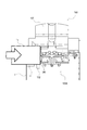
図2はシート処理装置となるフィニッシャ100を備えた画像形成装置502の制御系の構成を示すブロック図である。図2において、530は画像形成装置502本体の所定の位置に配置された制御手段となるCPU(Central Processing Unit;中央演算装置)回路部である。   FIG. 2 is a block diagram illustrating a configuration of a control system of the image forming apparatus 502 including the finisher 100 serving as a sheet processing apparatus. In FIG. 2, reference numeral 530 denotes a CPU (Central Processing Unit) circuit unit serving as a control unit disposed at a predetermined position of the main body of the image forming apparatus 502.

CPU回路部530は、CPU529、制御プログラム等を格納したROM(Read Only Memory;リードオンリメモリ)531を有する。更に、制御データを一時的に保持するための領域や、制御に伴う演算の作業領域として用いられるRAM(Randon Access Memory;ランダムアクセスメモリ)560を有している。   The CPU circuit unit 530 includes a CPU 529, a ROM (Read Only Memory) 531 storing a control program and the like. Furthermore, a RAM (Randon Access Memory) 560 used as an area for temporarily storing control data and a work area for operations associated with control is provided.

また、外部インターフェイス537は、画像形成装置502と、外部PC(コンピュータ)520との外部インターフェイスである。この外部インターフェイス537は、外部PC520からのプリントデータを受信すると、このデータをビットマップ画像に展開し、画像データとして画像信号制御部534へ出力する。   An external interface 537 is an external interface between the image forming apparatus 502 and an external PC (computer) 520. When the external interface 537 receives print data from the external PC 520, the external interface 537 develops the data into a bitmap image and outputs the data to the image signal control unit 534 as image data.

画像信号制御部534は、この画像データをプリンタ制御部535へ出力し、プリンタ制御部535は、画像信号制御部534からの画像データを図示しない露光制御部へ出力する。尚、イメージリーダ制御部533から画像信号制御部534へは、図1に示すイメージセンサ550aで読み取った原稿の画像が出力され、画像信号制御部534は、この画像出力をプリンタ制御部535へ出力する。   The image signal control unit 534 outputs the image data to the printer control unit 535, and the printer control unit 535 outputs the image data from the image signal control unit 534 to an exposure control unit (not shown). An image of the original read by the image sensor 550a shown in FIG. 1 is output from the image reader control unit 533 to the image signal control unit 534, and the image signal control unit 534 outputs this image output to the printer control unit 535. To do.

また、操作部501は、画像形成に関する各種機能を設定するための複数のキー及び設定状態を表示するための表示部等を有している。そして、ユーザによる各キーの操作に対応するキー信号をCPU回路部530に出力すると共に、該CPU回路部530からの信号に基づいて対応する情報を表示部に表示する。   The operation unit 501 includes a plurality of keys for setting various functions related to image formation, a display unit for displaying a setting state, and the like. Then, a key signal corresponding to the operation of each key by the user is output to the CPU circuit unit 530, and corresponding information is displayed on the display unit based on the signal from the CPU circuit unit 530.

CPU回路部530は、ROM531に格納された制御プログラム及び操作部501の設定に従って画像信号制御部534を制御すると共に、原稿搬送装置制御部532を介して図1に示す原稿搬送装置551を制御する。また、イメージリーダ制御部533を介して図1に示す原稿読み取り部550を制御する。また、プリンタ制御部535を介して図1に示す画像形成部503を制御する。また、フィニッシャ制御部536を介して図1に示すフィニッシャ100をそれぞれ制御する。   The CPU circuit unit 530 controls the image signal control unit 534 according to the control program stored in the ROM 531 and the setting of the operation unit 501, and controls the document conveying device 551 shown in FIG. 1 via the document conveying device control unit 532. . Further, the document reading unit 550 shown in FIG. 1 is controlled via the image reader control unit 533. Further, the printer controller 535 controls the image forming unit 503 shown in FIG. Further, the finisher 100 shown in FIG. 1 is controlled via the finisher control unit 536.

尚、本実施形態において、フィニッシャ制御部536はフィニッシャ100に搭載され、CPU回路部530のCPU529等との情報のやり取りを行うことによってフィニッシャ100の駆動制御を行う。また、フィニッシャ制御部536をCPU回路部530と一体的に画像形成装置502本体側に配設し、該画像形成装置502本体側から直接、フィニッシャ100を制御するようにしても良い。   In the present embodiment, the finisher control unit 536 is mounted on the finisher 100, and controls the driving of the finisher 100 by exchanging information with the CPU 529 and the like of the CPU circuit unit 530. Further, the finisher control unit 536 may be disposed integrally with the CPU circuit unit 530 on the main body side of the image forming apparatus 502, and the finisher 100 may be directly controlled from the main body side of the image forming apparatus 502.

<シート処理装置>
図3はシート処理装置となるフィニッシャ100の断面説明図である。本実施形態のフィニッシャ100は、画像形成装置502に設けられた画像形成手段となる画像形成部503に各搬送パスを介して接続され、画像形成部503により画像形成されたシート1に対して該フィニッシャ100によりシート処理を実施する。
<Sheet processing device>
FIG. 3 is a cross-sectional explanatory view of the finisher 100 serving as a sheet processing apparatus. The finisher 100 according to the present embodiment is connected to an image forming unit 503 serving as an image forming unit provided in the image forming apparatus 502 via each conveyance path, and the finisher 100 is connected to the sheet 1 on which an image is formed by the image forming unit 503. Sheet processing is performed by the finisher 100.

フィニッシャ100は、画像形成装置502本体から排出されたシート1を中間処理トレイ138へ順に取り込み、取り込んだ複数のシート1を整合して一つのシート束1nに束ねる処理を行なう。更に、取り込んだシート1の後端部1a付近に孔を開けるパンチ処理を行うようになっている。また、シート束1nの後端側をステイプラ132によりステイプルする綴じ処理、製本処理等の各種処理を行うようになっている。   The finisher 100 performs a process of sequentially taking the sheets 1 discharged from the main body of the image forming apparatus 502 into the intermediate processing tray 138, aligning the plurality of taken sheets 1 and bundling them into one sheet bundle 1n. Further, a punching process is performed in which a hole is formed in the vicinity of the rear end 1a of the sheet 1 taken in. Further, various processes such as a binding process for stapling the rear end side of the sheet bundle 1n by the stapler 132 and a bookbinding process are performed.

フィニッシャ100は、シート搬送手段となる搬送パス103,121,126によって搬送されたシート1を積載する中間積載手段となる中間処理トレイ138を有する。更に、中間処理トレイ138上でシート束1nをステイプルするステイプル部100A及びシート束1nを二つ折りにして製本するサドルユニット135等を備えている。   The finisher 100 includes an intermediate processing tray 138 serving as an intermediate stacking unit that stacks the sheets 1 transported by the transport paths 103, 121, and 126 serving as a sheet transport unit. Further, a stapling portion 100A for stapling the sheet bundle 1n on the intermediate processing tray 138, a saddle unit 135 for folding the sheet bundle 1n in half, and the like are provided.

フィニッシャ100は、画像形成装置502本体側の排出ローラ907により排出されたシート1を該フィニッシャ100内部に取り込むための入口ローラ102を備えている。画像形成装置502本体から排出されたシート1は入口ローラ102に受け渡される。尚、このとき、入口センサ101によりシート1の受渡しタイミングも同時に検知される。   The finisher 100 includes an entrance roller 102 for taking the sheet 1 discharged by the discharge roller 907 on the main body side of the image forming apparatus 502 into the finisher 100. The sheet 1 discharged from the main body of the image forming apparatus 502 is delivered to the entrance roller 102. At this time, the delivery timing of the sheet 1 is also detected by the inlet sensor 101 at the same time.

その後、入口ローラ102により搬送されたシート1は搬送パス103を通過しながら搬送ローラ105,106を経由して搬送ローラ110及び離間ローラ111により搬送されてバッファローラ115に達する。その後、シート1が上トレイ136上に排出される場合は、上パス切換部材118が図示しないソレノイド等の駆動手段により所定位置に切り替わる。これにより、シート1は上パス搬送パス117に導かれて上排出ローラ120により上トレイ136上に排出される。   Thereafter, the sheet 1 conveyed by the entrance roller 102 is conveyed by the conveyance roller 110 and the separation roller 111 via the conveyance rollers 105 and 106 while passing through the conveyance path 103 and reaches the buffer roller 115. Thereafter, when the sheet 1 is discharged onto the upper tray 136, the upper path switching member 118 is switched to a predetermined position by driving means such as a solenoid (not shown). As a result, the sheet 1 is guided to the upper path conveyance path 117 and discharged onto the upper tray 136 by the upper discharge roller 120.

シート1が上トレイ136上に排出されない場合は、バッファローラ115により搬送されたシート1は、図3の実線で示す状態の上パス切換部材118により搬送パス121に導かれる。その後、搬送ローラ122,124により順次搬送パス内を通過していく。   When the sheet 1 is not discharged onto the upper tray 136, the sheet 1 conveyed by the buffer roller 115 is guided to the conveyance path 121 by the upper path switching member 118 in the state indicated by the solid line in FIG. Thereafter, the rollers sequentially pass through the transport path by the transport rollers 122 and 124.

次に、フィニッシャ100に搬送されてきた複数枚のシート1をシート束1nとして綴じ手段となるステイプラ132により綴じる。その後、該シート束1nを順次積載する積載手段となる下トレイ137上に排出する。その場合は、図3の実線で示す状態のサドルパス切換部材125により搬送パス126に搬送される。   Next, a plurality of sheets 1 conveyed to the finisher 100 are bound by a stapler 132 serving as a binding unit as a sheet bundle 1n. Thereafter, the sheet bundle 1n is discharged onto a lower tray 137 serving as a stacking unit for sequentially stacking. In this case, the saddle path switching member 125 in the state shown by the solid line in FIG.

その後、下排出ローラ対128によりシート1は中間処理トレイ138上に排出される。そして、中間処理トレイ138上に排出されたシート1はパドル131やベルトローラ158等の戻し手段によりシート1を順次積載しながら整合し、整合積載されたシート束1nに対して処理を施すための中間処理トレイ138上で所定枚数だけ整合処理される。   Thereafter, the sheet 1 is discharged onto the intermediate processing tray 138 by the lower discharge roller pair 128. Then, the sheets 1 discharged onto the intermediate processing tray 138 are aligned while sequentially stacking the sheets 1 by the return means such as the paddle 131 and the belt roller 158, and the sheet bundle 1n that has been aligned and stacked is processed. A predetermined number of sheets are aligned on the intermediate processing tray 138.

中間処理トレイ138上で整合処理されたシート束1nは、必要に応じてステイプラ132により綴じ処理が施される。その後、シート束排出ローラ対130により下トレイ137上に排出される。   The sheet bundle 1n that has been aligned on the intermediate processing tray 138 is subjected to a binding process by a stapler 132 as necessary. Thereafter, the sheet bundle is discharged onto the lower tray 137 by the sheet bundle discharge roller pair 130.

一方、シート1をサドル(中綴じ)処理する場合には、図示しないソレノイド等の駆動手段によりサドルパス切換部材125を所定の位置に移動させる。これにより、シート1はサドルパス133に搬送され、サドル入口ローラ134によりサドルユニット135に導かれてサドル(中綴じ)処理される。   On the other hand, when the sheet 1 is subjected to saddle (saddle stitching) processing, the saddle path switching member 125 is moved to a predetermined position by driving means such as a solenoid (not shown). As a result, the sheet 1 is conveyed to the saddle path 133 and guided to the saddle unit 135 by the saddle entrance roller 134 to be subjected to saddle (saddle stitching) processing.

尚、搬送パス103,121,126を搬送中のシート1のタイミングは、搬送センサ104,123,127等によって、シート1の端部を検知しながら制御する。   Note that the timing of the sheet 1 being conveyed on the conveyance paths 103, 121, and 126 is controlled while detecting the edge of the sheet 1 by the conveyance sensors 104, 123, 127, and the like.

図4は本実施形態においてフィニッシャ100を制御するフィニッシャ制御部536の構成を示すブロック図である。フィニッシャ制御部536は、マイクロコンピュータからなるCPU701、RAM702、ROM703、入出力部(I/O)705、通信インターフェイス706、ネットワークインターフェイス704等を有して構成されている。   FIG. 4 is a block diagram illustrating a configuration of the finisher control unit 536 that controls the finisher 100 in the present embodiment. The finisher control unit 536 includes a CPU 701 formed of a microcomputer, a RAM 702, a ROM 703, an input / output unit (I / O) 705, a communication interface 706, a network interface 704, and the like.

入出力部(I/O)705には、搬送制御部707、中間処理トレイ制御部708及び綴じ制御部709が接続されている。搬送制御部707は、シート1の横レジ検知処理、シートバッファリング処理、搬送処理等の制御を行うものである。中間処理トレイ制御部708は、前整合板モータ340a、奥整合板モータ341a、パドル駆動モータ155a、シート束排出駆動モータ130a等の駆動制御を行う。   A conveyance control unit 707, an intermediate processing tray control unit 708 and a binding control unit 709 are connected to the input / output unit (I / O) 705. A conveyance control unit 707 performs control such as a lateral registration detection process, a sheet buffering process, and a conveyance process of the sheet 1. The intermediate processing tray control unit 708 performs drive control of the front alignment plate motor 340a, the back alignment plate motor 341a, the paddle drive motor 155a, the sheet bundle discharge drive motor 130a, and the like.

また、中間処理トレイ制御部708には、前整合板ホームポジションセンサ340b、奥整合板ホームポジションセンサ341b、パドル駆動ホームポジションセンサ155b等が接続されている。中間処理トレイ制御部708により中間処理トレイ138上(中間積載手段の上)にシート1を整合する整合手段となる図6に示す前整合板340及び奥整合板341の動作制御を行なう。更に、中間処理トレイ制御部708により図7に示す引き込みパドル131の動作制御を行なう。更に、中間処理トレイ制御部708により図5に示す揺動ガイド149の開閉制御を行なう。   Further, the front alignment plate home position sensor 340b, the back alignment plate home position sensor 341b, the paddle drive home position sensor 155b, and the like are connected to the intermediate processing tray control unit 708. The intermediate processing tray control unit 708 controls the operation of the front alignment plate 340 and the back alignment plate 341 shown in FIG. 6 as alignment means for aligning the sheets 1 on the intermediate processing tray 138 (on the intermediate stacking means). Further, the intermediate processing tray control unit 708 controls the operation of the pull-in paddle 131 shown in FIG. Further, the intermediate processing tray control unit 708 performs opening / closing control of the swing guide 149 shown in FIG.

これらの制御は、前整合板ホームポジションセンサ340b、奥整合板ホームポジションセンサ341b及びパドル駆動ホームポジションセンサ155bとによって行われる。更に、前整合板モータ340a、奥整合板モータ341a、パドル駆動モータ155a、シート束排出駆動モータ130a等によって行われる。また、綴じ制御部709には、クリンチカムモータ132a及びクリンチカムホームポジションセンサ303b等が接続されている。   These controls are performed by the front alignment plate home position sensor 340b, the back alignment plate home position sensor 341b, and the paddle drive home position sensor 155b. Further, it is performed by a front alignment plate motor 340a, a back alignment plate motor 341a, a paddle drive motor 155a, a sheet bundle discharge drive motor 130a, and the like. The binding control unit 709 is connected to a clinch cam motor 132a, a clinch cam home position sensor 303b, and the like.

<綴じ処理部>
次に図5を用いて中間処理トレイ138を備えた綴じ処理部の構成について説明する。図5に示すように、中間処理トレイ138は、シート束1nの排出方向に対して下流側(図5の左側)を上方に、上流側(図5の右側)を下方に傾斜して配設されている。中間処理トレイ138の上流側である下方端部には後端ストッパ150が配置されている。尚、中間処理トレイ138は水平であっても良い。
<Binding processing unit>
Next, the configuration of the binding processing unit including the intermediate processing tray 138 will be described with reference to FIG. As shown in FIG. 5, the intermediate processing tray 138 is disposed with the downstream side (left side in FIG. 5) inclined upward and the upstream side (right side in FIG. 5) inclined downward with respect to the discharge direction of the sheet bundle 1n. Has been. A rear end stopper 150 is disposed at the lower end on the upstream side of the intermediate processing tray 138. The intermediate processing tray 138 may be horizontal.

図5及び図6に示すように、中間処理トレイ138の中間部には前整合部340c及び奥整合部341cが設けられている。更に、図14に示すように、中間処理トレイ138に排出されたシート1の幅方向の両側端部1c,1dの位置を規制する側端規制部が設けられている。   As shown in FIGS. 5 and 6, a front alignment portion 340c and a back alignment portion 341c are provided in the intermediate portion of the intermediate processing tray 138. Further, as shown in FIG. 14, side end regulating portions for regulating the positions of both side end portions 1 c and 1 d in the width direction of the sheet 1 discharged to the intermediate processing tray 138 are provided.

ここで、前整合部340c及び奥整合部341cは、整合面を構成する整合部340d,341dをそれぞれ有する前整合板340及び奥整合板341を有する。更に、前整合板340及び奥整合板341を夫々独立して駆動する前整合板モータ340a及び奥整合板モータ341aとを備えている。   Here, the front alignment portion 340c and the back alignment portion 341c include a front alignment plate 340 and a back alignment plate 341 having alignment portions 340d and 341d constituting the alignment surface, respectively. Further, a front alignment plate motor 340a and a back alignment plate motor 341a for independently driving the front alignment plate 340 and the back alignment plate 341 are provided.

そして、シート1の両側端位置を規制する際は以下の通りである。前整合板モータ340a及び奥整合板モータ341aの駆動を該前整合板モータ340a及び奥整合板モータ341aと共に移動手段を構成するタイミングベルト340e,341eを介してそれぞれ前整合板340及び奥整合板341に伝達する。   And when restrict | limiting the both-ends position of the sheet | seat 1, it is as follows. The front alignment plate motor 340a and the back alignment plate motor 341a are driven by timing belts 340e and 341e which constitute moving means together with the front alignment plate motor 340a and the back alignment plate motor 341a, respectively. To communicate.

これにより、前整合板340及び奥整合板341は、中間処理トレイ138に対して幅方向に沿って独立して移動し、該中間処理トレイ138上に積載されたシート1の両側端に当接してシート1を整合する。   As a result, the front alignment plate 340 and the back alignment plate 341 move independently along the width direction with respect to the intermediate processing tray 138, and come into contact with both side edges of the sheets 1 stacked on the intermediate processing tray 138. To align the sheet 1.

即ち、前整合板340と奥整合板341は、中間処理トレイ138上に各整合部(整合面)340d,341dを対向させて配置される。更に、図6の上下方向で示す整合方向に正逆移動可能なように組み付けられている。   That is, the front alignment plate 340 and the back alignment plate 341 are arranged on the intermediate processing tray 138 with the alignment portions (alignment surfaces) 340d and 341d facing each other. Furthermore, it is assembled so that it can move forward and backward in the alignment direction shown by the vertical direction in FIG.

この結果、シート1(或いはシート束1n)が幅方向にズレて搬送されてきた場合でも、この前整合板340及び奥整合板341により中間処理トレイ138上のシート1(或いはシート束1n)の幅方向の位置を正しい位置に整合することが出来る。   As a result, even when the sheet 1 (or sheet bundle 1n) is conveyed while being shifted in the width direction, the sheet 1 (or sheet bundle 1n) on the intermediate processing tray 138 is moved by the front alignment plate 340 and the back alignment plate 341. The position in the width direction can be aligned with the correct position.

一方の整合板である、例えば前整合板340の整合面を構成する整合部340dは図6の上下方向で示すシート1の幅方向に移動可能に設けられている。また、この整合部340dと前整合板340の装置フレーム340fとの間には、引っ張りバネ345が設けられている。   One alignment plate, for example, an alignment portion 340d constituting the alignment surface of the front alignment plate 340 is provided to be movable in the width direction of the sheet 1 shown in the vertical direction in FIG. Further, a tension spring 345 is provided between the aligning portion 340d and the device frame 340f of the front aligning plate 340.

この引っ張りバネ345と移動リンク346,347により、整合部340dは所定量Lだけシート1側に突出するようになっている。尚、後述するように、シート1の側端位置を規制する際、整合部340dがシート1に圧接すると、圧接部である整合部340dは引っ張りバネ345に抗しながら装置フレーム340f側に移動する。   By the tension spring 345 and the movement links 346 and 347, the alignment portion 340d protrudes toward the sheet 1 by a predetermined amount L. As will be described later, when the side end position of the sheet 1 is regulated, when the aligning portion 340d is in pressure contact with the sheet 1, the aligning portion 340d as the press contact portion moves toward the apparatus frame 340f while resisting the tension spring 345. .

尚、図6において、340b,341bは前整合板ホームポジションセンサ及び奥整合板ホームポジションセンサである。この前整合板ホームポジションセンサ340b及び奥整合板ホームポジションセンサ341bにより前整合板340及び奥整合板341のそれぞれのホームポジションを検知する。   In FIG. 6, 340b and 341b are a front alignment plate home position sensor and a back alignment plate home position sensor. The home positions of the front alignment plate 340 and the back alignment plate 341 are detected by the front alignment plate home position sensor 340b and the back alignment plate home position sensor 341b.

前整合板ホームポジションセンサ340b及び奥整合板ホームポジションセンサ341bを備える。これによりフィニッシャ100が動作しないとき、前整合板340及び奥整合板341をそれぞれ両端部に位置するところに設定された各ホームポジションに待機させることが出来る。   A front alignment plate home position sensor 340b and a back alignment plate home position sensor 341b are provided. As a result, when the finisher 100 does not operate, the front alignment plate 340 and the back alignment plate 341 can be made to stand by at their home positions set at both ends.

また、中間処理トレイ138の引き込み方向下流側である図5の上方端部には図7に示す引き込みパドル131と、図13(a)に示す揺動ガイド149とが配置されている。ここで、図7に示す引き込みパドル131は、中間処理トレイ138の上方に配設され、図7に示すパドル駆動モータ155aによって回転する駆動軸157上に該駆動軸157に沿って複数固定されている。図7に示す引き込みパドル131は、パドル駆動モータ155aにより適切なタイミングで駆動軸157を中心に図5の反時計回り方向に回転するようになっている。   Further, a pull-in paddle 131 shown in FIG. 7 and a swing guide 149 shown in FIG. 13A are arranged at the upper end of FIG. 5, which is the downstream side of the intermediate processing tray 138 in the pull-in direction. Here, the drawing paddle 131 shown in FIG. 7 is disposed above the intermediate processing tray 138, and a plurality of the drawing paddles 131 are fixed along the driving shaft 157 on the driving shaft 157 rotated by the paddle driving motor 155a shown in FIG. Yes. The pull-in paddle 131 shown in FIG. 7 is rotated counterclockwise in FIG. 5 around the drive shaft 157 at an appropriate timing by a paddle drive motor 155a.

図5に示す下排出ローラ対128を構成するローラ128a,128bにより挟持排出されたシート1は以下の通り滑降する。中間処理トレイ138の傾斜配置及び引き込みパドル131の回転作用によって、該中間処理トレイ138の積載面上、または中間処理トレイ138上に積載されたシート1上を滑降する。   The sheet 1 nipped and discharged by the rollers 128a and 128b constituting the lower discharge roller pair 128 shown in FIG. 5 slides down as follows. Due to the inclined arrangement of the intermediate processing tray 138 and the rotational action of the pull-in paddle 131, the intermediate processing tray 138 slides down on the stacking surface of the intermediate processing tray 138 or the sheets 1 stacked on the intermediate processing tray 138.

このように滑降したシート1は、その後、シート搬送手段としてのベルトローラ158の図5の反時計回り方向の回転によって、該シート1の後端部1a(排出方向上流側の端部)がストッパとなる後端ストッパ150に突き当てられて停止する。   After the sheet 1 has slid down in this manner, the rear end 1a (the upstream end in the discharge direction) of the sheet 1 is stopped by the rotation of the belt roller 158 as the sheet conveying means in the counterclockwise direction in FIG. The rear end stopper 150 comes into contact with and stops.

尚、図5に示すように、ベルトローラ158は、その下方部が中間処理トレイ138上に積載された最上位のシート1と接するような位置関係で該中間処理トレイ138の上方に設けられている。また、ベルトローラ158は、下排出ローラ対128を構成するローラ128aの外周に掛けられ、該ローラ128aの回転に従動して図5の反時計回り方向に回転する。   As shown in FIG. 5, the belt roller 158 is provided above the intermediate processing tray 138 in such a positional relationship that the lower portion thereof is in contact with the uppermost sheet 1 stacked on the intermediate processing tray 138. Yes. Further, the belt roller 158 is hung on the outer periphery of the roller 128a constituting the lower discharge roller pair 128, and rotates in the counterclockwise direction of FIG. 5 following the rotation of the roller 128a.

一方、シート排出部を構成する揺動ガイド149は、中間処理トレイ138の下流側端部に設けられた下部排出ローラ130cと共に図3に示すシート束排出ローラ対130を構成する上部排出ローラ130bを回転自在に保持している。   On the other hand, the swing guide 149 that constitutes the sheet ejection unit includes the upper ejection roller 130b that constitutes the sheet bundle ejection roller pair 130 shown in FIG. 3 together with the lower ejection roller 130c provided at the downstream end of the intermediate processing tray 138. Holds freely.

揺動ガイド149の図5の上下方向の揺動動作に伴って上部排出ローラ130bは、下部排出ローラ130cに対して接離するようになっている。尚、シート束排出ローラ対130(例えば、下部排出ローラ130c)は、図4に示すシート束排出駆動モータ130aによって正逆回転するようになっている。   As the swing guide 149 swings in the vertical direction in FIG. 5, the upper discharge roller 130b comes into contact with and separates from the lower discharge roller 130c. Note that the sheet bundle discharge roller pair 130 (for example, the lower discharge roller 130c) is rotated forward and backward by a sheet bundle discharge drive motor 130a shown in FIG.

また、このシート束排出ローラ対130の一方のローラである上部排出ローラ130bを保持する保持部材である揺動ガイド149は、揺動ガイド開閉モータ180からの駆動により支持軸154を支点として図5の上下方向に揺動するようになっている。   Further, the swing guide 149, which is a holding member for holding the upper discharge roller 130b, which is one roller of the sheet bundle discharge roller pair 130, is driven by the swing guide opening / closing motor 180 with the support shaft 154 as a fulcrum as shown in FIG. Swings up and down.

通常、シート1が中間処理トレイ138上に排出されるとき、揺動ガイド149は支持軸154を支点として図5の上方へ揺動する。これに伴って上部排出ローラ130bがシート束排出ローラ対130の他方のローラである下部排出ローラ130cから離れた開口状態となる。   Normally, when the sheet 1 is discharged onto the intermediate processing tray 138, the swing guide 149 swings upward in FIG. 5 with the support shaft 154 as a fulcrum. Accordingly, the upper discharge roller 130b is opened away from the lower discharge roller 130c which is the other roller of the sheet bundle discharge roller pair 130.

また、中間処理トレイ138上でのシート1の処理が終了したとき、揺動ガイド149は支持軸154を支点として図5の下方に揺動し、上部排出ローラ130bと下部排出ローラ130cとによりシート束1nを挟持する。その後、上部排出ローラ130bと下部排出ローラ130cとによりシート束1nを挟持した状態でシート束排出ローラ対130が回転する。これによりシート束1nは下トレイ137上に排出される。   Further, when the processing of the sheet 1 on the intermediate processing tray 138 is completed, the swing guide 149 swings downward in FIG. 5 with the support shaft 154 as a fulcrum, and the upper discharge roller 130b and the lower discharge roller 130c cause the sheet to swing. The bundle 1n is clamped. Thereafter, the sheet bundle discharge roller pair 130 rotates with the sheet bundle 1n held between the upper discharge roller 130b and the lower discharge roller 130c. As a result, the sheet bundle 1n is discharged onto the lower tray 137.

図5に示すように、揺動ガイド149には、下排出ローラ対128から中間処理トレイ138内へシート1を排出する際のシート1の表面電荷を除去する第一除電針152が駆動軸157の軸方向に渡って配置されている。   As shown in FIG. 5, the swing guide 149 has a first discharge needle 152 for removing the surface charge of the sheet 1 when the sheet 1 is discharged from the lower discharge roller pair 128 into the intermediate processing tray 138. It is arranged over the axial direction.

更に、揺動ガイド149には、上部排出ローラ130bの下流部に位置し、シート束排出ローラ対130により排出されるシート1の表面電荷を除去する第二除電針153が駆動軸157の軸方向に渡って配置されている。   Further, the swing guide 149 has a second static elimination needle 153 that is positioned downstream of the upper discharge roller 130 b and removes the surface charge of the sheet 1 discharged by the sheet bundle discharge roller pair 130 in the axial direction of the drive shaft 157. It is arranged over.

<綴じ手段>
綴じ手段となるステイプラ132は、図4に示すクリンチカムモータ132aによって駆動されてシート束1nの端部を綴じ処理する。ステイプラ132は中間処理トレイ138上に固定されている。
<Binding means>
The stapler 132 serving as a binding unit is driven by a clinch cam motor 132a shown in FIG. 4 to bind the end portion of the sheet bundle 1n. The stapler 132 is fixed on the intermediate processing tray 138.

ステイプラ132は中間処理トレイ138上に積載されたシート束1nのコーナー部において綴じ処理を施す。   The stapler 132 performs a binding process at a corner portion of the sheet bundle 1n stacked on the intermediate processing tray 138.

中間処理トレイ138上に固定されたステイプラ132と、シート束1nの綴じ部とが一致するように図6に示す前整合板340と奥整合板341とによって、シート1を幅方向に移動させることで、異なるサイズのシート束1nの綴じ処理を行う。   The sheet 1 is moved in the width direction by the
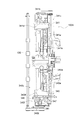
 front alignment plate 340 and the back alignment plate 341 shown in FIG. 6 so that the stapler 132 fixed on the intermediate processing tray 138 matches the binding portion of the sheet bundle 1n. Thus, the binding processing of the sheet bundle 1n having different sizes is performed.

<針無し綴じ部>
次に、図8〜図11を用いてステイプラ132の構成について説明する。図8はステイプラ132の構成を示す斜視説明図である。図9(a)はステイプラ132の構成を示す左側面図である。図9(b)はステイプラ132の構成を示す正面説明図である。図10(a),(b)及び図11(a),(b)はステイプラ132の動作を説明する断面説明図である。
<Needleless binding part>
Next, the configuration of the stapler 132 will be described with reference to FIGS. FIG. 8 is an explanatory perspective view showing the configuration of the stapler 132. FIG. 9A is a left side view showing the configuration of the stapler 132. FIG. 9B is an explanatory front view showing the configuration of the stapler 132. FIGS. 10A and 10B and FIGS. 11A and 11B are cross-sectional explanatory views for explaining the operation of the stapler 132. FIG.

ステイプラ132は、図8及び図9に示すように、シート束1nに図10(b)に示す半抜きの舌状片1pを形成するための半抜きポンチ601がポンチホルダ603に固定されて設けられる。更に、該半抜きポンチ601により形成された半抜き舌状片1pの先端部1p1を差し込むためのスリット1sを形成するための図10(a)に示すスリットポンチ602がポンチホルダ603に固定されている。   As shown in FIGS. 8 and 9, the stapler 132 is provided with a half punch punch 601 for fixing a punch punch holder 603 for forming a half punch tongue piece 1p shown in FIG. . Further, a slit punch 602 shown in FIG. 10A for fixing a slit 1 s for inserting a tip 1 p 1 of the half-cut tongue-like piece 1 p formed by the half-cut punch 601 is fixed to the punch holder 603. .

綴じ手段となるステイプラ132は、中間処理トレイ138上(中間積載手段の上)に積載されたシート束1nに対して一部が各シート1と連結した状態で半抜きポンチ601により切削された半抜き舌状片1pを各シート1に形成する。更に、スリットポンチ602により切削された貫通穴からなるスリット1sを各シート1に形成する。そして、シート束1nの各半抜き舌状片1pの先端部1p1を該シート束1nの各スリット1sに一体的に挿入する。これにより該シート束1nの端部を綴じる。   A stapler 132 serving as a binding unit is cut by a half punching punch 601 in a state where a part is connected to each sheet 1 with respect to the sheet bundle 1n stacked on the intermediate processing tray 138 (on the intermediate stacking unit). The extracted tongue-shaped piece 1p is formed on each sheet 1. Further, slits 1 s formed of through holes cut by the slit punch 602 are formed in each sheet 1. Then, the tip end portion 1p1 of each half-blanked tongue-shaped piece 1p of the sheet bundle 1n is integrally inserted into each slit 1s of the sheet bundle 1n. As a result, the end of the sheet bundle 1n is bound.

図10(a)に示すように、図10(a)の上下方向に移動可能なポンチホルダ603の対向側にはダイ604が図示しない装置フレームに対して固定配置されている。ダイ604には、半抜きポンチ601と、スリットポンチ602とが貫通するための一連の貫通穴604aが形成されている。   As shown in FIG. 10A, a die 604 is fixedly arranged with respect to a device frame (not shown) on the opposite side of the punch holder 603 that can move in the vertical direction in FIG. The die 604 has a series of through holes 604a through which the half punch 601 and the slit punch 602 pass.

ポンチホルダ603とダイ604との間には、シート束1nが収納出来る離間間隔tを設けてスライド支持板605が図示しない装置フレームに対して固定配置されている。   Between the punch holder 603 and the die 604, there is provided a separation interval t in which the sheet bundle 1n can be stored, and the slide support plate 605 is fixedly arranged with respect to an apparatus frame (not shown).

スライド支持板605の上面605eには複数のスライド軸606が立設されており、ポンチホルダ603に設けられた貫通穴603b内をスライド軸606が移動可能に挿通されている。これによりポンチホルダ603がスライド軸606に沿って図10(a)の上下方向にスライド可能に構成される。   A plurality of slide shafts 606 are erected on the upper surface 605e of the slide support plate 605, and the slide shaft 606 is movably inserted through a through hole 603b provided in the punch holder 603. Accordingly, the punch holder 603 is configured to be slidable in the vertical direction of FIG.

スライド軸606の外周には、該スライド軸606の外径よりも大きい内径を有する圧縮バネ607が嵌装されている。圧縮バネ607はスライド軸606と同軸上で、且つポンチホルダ603の下面603cと、スライド支持板605の上面605eとの間に配置されている。このためポンチホルダ603には圧縮バネ607の伸長力により常に図10(a)の上方へと持ち上げられる力が働くようになっている。   A compression spring 607 having an inner diameter larger than the outer diameter of the slide shaft 606 is fitted on the outer periphery of the slide shaft 606. The compression spring 607 is coaxial with the slide shaft 606 and is disposed between the lower surface 603 c of the punch holder 603 and the upper surface 605 e of the slide support plate 605. Therefore, the punch holder 603 is always subjected to a force that is lifted upward in FIG. 10A by the extension force of the compression spring 607.

ポンチホルダ603の図10(a)の上方には、カム軸609を中心に回転する偏芯カム608が該ポンチホルダ603の上面603aと接触可能に配置されている。偏芯カム608のカム軸609の近傍には偏芯カム608を回転させる駆動源となる図4に示すクリンチカムモータ132aが設けられている。   An eccentric cam 608 that rotates about the cam shaft 609 is disposed above the punch holder 603 in FIG. 10A so as to be in contact with the upper surface 603 a of the punch holder 603. A clinch cam motor 132a shown in FIG. 4 serving as a drive source for rotating the eccentric cam 608 is provided in the vicinity of the cam shaft 609 of the eccentric cam 608.

クリンチカムモータ132aの回転駆動によりカム軸609を中心に偏芯カム608が回転する。これにより偏芯カム608の長径部のカム面608aがポンチホルダ603の上面603aを圧縮バネ607の伸長力に抗して図10(a)の下方向に押す。或いは、偏芯カム608の短径部のカム面608aがポンチホルダ603の上面603aに当接する際には圧縮バネ607の伸長力によりポンチホルダ603は図10(a)の上方向に退避する。これにより偏芯カム608の回転に伴ってポンチホルダ603を図10(a)の上下方向に自在に昇降させることが出来る。   The eccentric cam 608 rotates about the cam shaft 609 by the rotation drive of the clinch cam motor 132a. As a result, the cam surface 608a of the long diameter portion of the eccentric cam 608 pushes the upper surface 603a of the punch holder 603 in the downward direction of FIG. Alternatively, when the cam surface 608a of the short diameter portion of the eccentric cam 608 comes into contact with the upper surface 603a of the punch holder 603, the punch holder 603 is retracted upward in FIG. As a result, the punch holder 603 can be moved up and down freely in the vertical direction of FIG. 10A as the eccentric cam 608 rotates.

図8に示すように、偏芯カム608のカム軸609上にはカムホームポジションフラグ610が取り付けられている。更に、該カムホームポジションフラグ610の位置を検出するためのクリンチカムホームポジションセンサ303bが設けられている。   As shown in FIG. 8, a cam home position flag 610 is attached on the cam shaft 609 of the eccentric cam 608. Further, a clinch cam home position sensor 303b for detecting the position of the cam home position flag 610 is provided.

本実施形態ではポンチホルダ603が図8の上方位置にあるとき、つまり半抜きポンチ601とスリットポンチ602とがスライド支持板605とダイ604との間に形成されるシート束収納部6から退避した位置をホームポジションとして設定している。   In this embodiment, when the punch holder 603 is at the upper position in FIG. 8, that is, the position where the half punch 601 and the slit punch 602 are retracted from the sheet bundle storage portion 6 formed between the slide support plate 605 and the die 604. Is set as the home position.

スライド支持板605には、半抜きポンチ601が貫通可能な貫通穴605aと、スリットポンチ602が貫通可能な貫通穴605bとが開けられている。   The slide support plate 605 has a through hole 605a through which the half punch 601 can pass and a through hole 605b through which the slit punch 602 can pass.

半抜きポンチ601はシート束1nに半抜き舌状片1pを形成する。このためにポンチホルダ603のスライド方向(図8の上下方向)から見た半抜きポンチ601の切削刃の断面形状は図12に示す半抜き舌状片1pを切削したU字形状の切削部1uに対応するU字型となっている。   The half punch punch 601 forms a half punch tongue 1p on the sheet bundle 1n. For this purpose, the sectional shape of the cutting blade of the half punch punch 601 as viewed from the sliding direction of the punch holder 603 (vertical direction in FIG. 8) is the U-shaped cutting portion 1u obtained by cutting the half punch tongue piece 1p shown in FIG. It has a corresponding U shape.

図8及び図10(b)に示すように、半抜きポンチ601の切削刃の内側にはコ字型をした折り返しレバー611がレバー回動軸612を中心に回動可能に設けられている。折り返しレバー611は半抜きポンチ601によって形成された図10(b)に示す半抜き舌状片1pをスリット1s側へと折り返す。   As shown in FIGS. 8 and 10 (b), a U-shaped folding lever 611 is provided inside the cutting blade of the half punching punch 601 so as to be rotatable around a lever rotating shaft 612. The folding lever 611 folds the half-cut tongue-shaped piece 1p formed by the half-cut punch 601 shown in FIG. 10B toward the slit 1s.

また、図8及び図11(a)に示すように、スリットポンチ602には貫通穴602aが形成されている。貫通穴602aは折り返しレバー611がレバー回動軸612を中心に回動した際に該折り返しレバー611の舌状片押し面611a及び半抜き舌状片1pの先端部1p1が貫通する。   As shown in FIGS. 8 and 11A, the slit punch 602 has a through hole 602a. When the folding lever 611 rotates about the lever rotation shaft 612, the through hole 602a penetrates the tongue-like piece pushing surface 611a of the folding lever 611 and the tip 1p1 of the half-blanked tongue-like piece 1p.

図10(a)に示すように、折り返しレバー611のレバー回動軸612の回動中心よりも図10(a)の上方には、引っ張りバネ613の一端が係止される引っ掛け部611cが設けられている。引っ張りバネ613の他端はスリットポンチ602に係止されている。これにより引っ張りバネ613を介して折り返しレバー611とスリットポンチ602とが係合されている。   As shown in FIG. 10 (a), a hooking portion 611c to which one end of the tension spring 613 is locked is provided above the turning center of the lever turning shaft 612 of the folding lever 611 in FIG. 10 (a). It has been. The other end of the tension spring 613 is locked to the slit punch 602. Accordingly, the folding lever 611 and the slit punch 602 are engaged via the tension spring 613.

図10(a)に示すように、偏芯カム608の短径部のカム面608aがポンチホルダ603の上面603aに当接して該ポンチホルダ603が圧縮バネ607の伸長力により図10(a)の上方向に退避したホームポジションにある。そのときは、折り返しレバー611の舌状片押し面611aが半抜きポンチ601の切削刃の内側に常に収納された状態で保持される。   As shown in FIG. 10A, the cam surface 608a of the short diameter portion of the eccentric cam 608 contacts the upper surface 603a of the punch holder 603 so that the punch holder 603 is The home position is retracted in the direction. At that time, the tongue-like piece pressing surface 611a of the folding lever 611 is held in a state of being always stored inside the cutting blade of the half punching punch 601.

一方、図11(a)に示すように、偏芯カム608の長径部のカム面608aが圧縮バネ607の伸長力に抗してポンチホルダ603の上面603aを押圧して該ポンチホルダ603が図11(a)の下方へ移動して図11(a)に示すように最下点に達する。その際に、折り返しレバー611がレバー回動軸612を中心に図11(a)の反時計回り方向に回動して舌状片押し面611aが図8に示す貫通穴602aを貫通してスリットポンチ602から突出する。   On the other hand, as shown in FIG. 11 (a), the cam surface 608a of the long diameter portion of the eccentric cam 608 presses the upper surface 603a of the punch holder 603 against the extension force of the compression spring 607 so that the punch holder 603 is shown in FIG. It moves below a) and reaches the lowest point as shown in FIG. At this time, the folding lever 611 rotates about the lever rotation shaft 612 in the counterclockwise direction of FIG. 11A, and the tongue-like pressing surface 611a passes through the through hole 602a shown in FIG. Projects from the punch 602.

折り返しレバー611には、スライド支持板605の当接面605cと当接する当接面611bが設けられている。図11(a)に示すように、ポンチホルダ603が最下点まで下降した際にスライド支持板605に設けられた二つの貫通穴605a,605bの間にある当接面605cと、折り返しレバー611の当接面611bとが当接する。これにより折り返しレバー611がレバー回動軸612を中心に図11(a)の反時計回り方向に回動して舌状片押し面611aが図8に示す貫通穴602aを貫通してスリットポンチ602から突出する構成となっている。   The folding lever 611 is provided with a contact surface 611b that contacts the contact surface 605c of the slide support plate 605. As shown in FIG. 11A, when the punch holder 603 is lowered to the lowest point, the contact surface 605c provided between the two through holes 605a and 605b provided in the slide support plate 605, the folding lever 611 The contact surface 611b contacts. As a result, the folding lever 611 rotates about the lever rotation shaft 612 in the counterclockwise direction of FIG. 11A, and the tongue-like pressing surface 611a passes through the through hole 602a shown in FIG. It is the structure which protrudes from.

尚、半抜きポンチ601により切削されてシート束1nに形成される半抜き舌状片1pの形成動作、及びスリットポンチ602により切削されてシート束1nに形成されるスリット1sに該半抜き舌状片1pを折り込む動作の詳細については後述する。   Incidentally, the forming operation of the half-cut tongue piece 1p cut by the half punch punch 601 and formed in the sheet bundle 1n, and the half punch tongue shape in the slit 1s cut by the slit punch 602 and formed in the sheet bundle 1n. Details of the operation of folding the piece 1p will be described later.

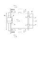
図9(a),(b)に示すように、ダイ604及びスライド支持板605には、それぞれ半抜きポンチ601及びスリットポンチ602を起点にして異なる複数の方向に延伸された凹部604c,605dが設けられている。凹部604c,605dはダイ604とスライド支持板605とのそれぞれの端部に設けられる平担部相互の離間間隔tよりもそれぞれ大きな離間間隔Ya,Ybを有する。   As shown in FIGS. 9A and 9B, the die 604 and the slide support plate 605 have recesses 604c and 605d extending in different directions starting from the half punch punch 601 and the slit punch 602, respectively. Is provided. The recesses 604c and 605d have separation intervals Ya and Yb larger than the separation interval t between the flat support portions provided at the ends of the die 604 and the slide support plate 605, respectively.

図8に示すように、綴じ手段となるステイプラ132のガイド面となるダイ604及びスライド支持板605に、互いに異なる方向に延伸された複数の凹部604c,605dが設けられる。互いに異なる方向に延伸された複数の凹部604c,605dは、綴じ手段となるステイプラ132のガイド面となるダイ604及びスライド支持板605の少なくとも一方に設けることでも良い。   As shown in FIG. 8, a plurality of recesses 604c and 605d extending in different directions are provided on a die 604 and a slide support plate 605 that serve as a guide surface of a stapler 132 serving as a binding means. The plurality of recesses 604c and 605d extending in different directions may be provided on at least one of the die 604 and the slide support plate 605 that serve as the guide surface of the stapler 132 that serves as the binding means.

本実施形態の凹部604c,605dは、シート束1nの綴じ部位から異なる複数の方向(本実施形態では直交する方向)に延伸されている。尚、一方のガイド面(ダイ604かスライド支持板605の何れか一方)にシート束1nの綴じ部位から異なる複数の方向(本実施形態では直交する方向)に延伸された凹部604cか凹部605dの何れかを設けることでも良い。   The concave portions 604c and 605d of the present embodiment are extended from a binding portion of the sheet bundle 1n in a plurality of different directions (perpendicular directions in the present embodiment). In addition, the concave portion 604c or the concave portion 605d extended in a plurality of different directions (directions orthogonal in the present embodiment) from the binding portion of the sheet bundle 1n on one guide surface (one of the die 604 and the slide support plate 605). Either may be provided.

本実施形態では、ダイ604及びスライド支持板605に設けられた凹部604c,605dは、それぞれ半抜きポンチ601及びスリットポンチ602を起点にして図3に示す積載手段となる下トレイ137へ向かう方向(図8の矢印D方向)に延伸されている。更に、下トレイ137へ向かう方向と直交する方向(図8の矢印E方向)に延伸されている。   In the present embodiment, the recesses 604c and 605d provided on the die 604 and the slide support plate 605 are directed from the half punch punch 601 and the slit punch 602 toward the lower tray 137 serving as the stacking means shown in FIG. It is extended in the direction of arrow D in FIG. Furthermore, it is extended in a direction perpendicular to the direction toward the lower tray 137 (the direction of arrow E in FIG. 8).

綴じ手段となるステイプラ132によるシート束1nの綴じ処理後に該ステイプラ132のスライド支持板605とダイ604との間の離間間隔tからなる間口内から綴じ処理後のシート束1nを移動させる方向が少なくとも二つの方向を有する。   After the binding process of the sheet bundle 1n by the stapler 132 serving as the binding means, at least a direction in which the sheet bundle 1n after the binding process is moved from the inside opening formed by the separation interval t between the slide support plate 605 and the die 604 of the stapler 132 is at least. Has two directions.

尚、図示しないが、ダイ604及びスライド支持板605に、それぞれ半抜きポンチ601及びスリットポンチ602を起点にして放射線状に少なくとも二つ以上の方向の凹部604c,605dを設けることも出来る。この場合、ステイプラ132のスライド支持板605とダイ604との間の離間間隔tからなる間口内から綴じ処理後のシート束1nを移動させる方向が少なくとも二つ以上の方向を有する構成とすることが出来る。   Although not shown, the die 604 and the slide support plate 605 may be provided with concave portions 604c and 605d in at least two directions radially from the half punch punch 601 and the slit punch 602, respectively. In this case, it is preferable that the direction in which the sheet bundle 1n after the binding process is moved from the front opening formed by the separation interval t between the slide support plate 605 of the stapler 132 and the die 604 has at least two directions. I can do it.

これによりシート束1nの針無し綴じ処理後に図22に示すように、該シート束1nのシート面1n1から部分的に突出した挿し込み綴じ部1rと、ダイ604及びスライド支持板605のガイド面とが干渉することが無い。そして、半抜きポンチ601及びスリットポンチ602を起点にして直線状に延伸されている凹部604c,605d内をシート面1n1から部分的に突出した挿し込み綴じ部1rが容易に通過出来る。これにより綴じ処理後のシート束1nを凹部604c,605dに沿って容易に移動することが出来る。   Thus, as shown in FIG. 22 after the stapleless binding processing of the sheet bundle 1n, the insertion binding portion 1r partially protruding from the sheet surface 1n1 of the sheet bundle 1n, the guide surface of the die 604 and the slide support plate 605, Will not interfere. Then, the insertion binding portion 1r partially protruding from the sheet surface 1n1 can easily pass through the recesses 604c and 605d linearly extending from the half punch punch 601 and the slit punch 602. Thereby, the sheet bundle 1n after the binding process can be easily moved along the recesses 604c and 605d.

ダイ604及びスライド支持板605に設けられた凹部604c,605dは、図8及び図20(a),(b)に示すように、図8の矢印D方向で示す積載手段となる下トレイ137へ向かう方向となるシート束1nの搬送方向に延伸して設けられている。更に、図8の矢印E方向で示す該シート束1nの搬送方向と直交するシート束1nの幅方向に延伸して設けられている。   Recesses 604c and 605d provided on the die 604 and the slide support plate 605, as shown in FIGS. 8 and 20 (a) and 20 (b), are directed to the lower tray 137 serving as a stacking means shown in the direction of arrow D in FIG. The sheet bundle 1n is provided so as to extend in the transport direction. Further, the sheet bundle 1n is provided so as to extend in the width direction perpendicular to the conveying direction of the sheet bundle 1n shown by the arrow E direction in FIG.

一方、図9(a),(b)に示すように、ダイ604及びスライド支持板605の端部には、凹部604c,605dの離間間隔Ya,Ybよりも小さな離間間隔tを有する平担部が設けられている。これによりステイプラ132の処理能力以上の厚さを有するシート束1nがダイ604とスライド支持板605との間に挿入されないようにシート束1nの厚さを制限することが出来る。   On the other hand, as shown in FIGS. 9 (a) and 9 (b), at the end portions of the die 604 and the slide support plate 605, a flat support portion having a separation interval t smaller than the separation intervals Ya and Yb of the recesses 604c and 605d. Is provided. Accordingly, the thickness of the sheet bundle 1n can be limited so that the sheet bundle 1n having a thickness greater than the processing capability of the stapler 132 is not inserted between the die 604 and the slide support plate 605.

<針無し綴じ動作>
次に図10(a),(b)及び図11(a),(b)を用いてステイプラ132によるシート束1nに対する針無し綴じ動作について説明する。図10(a)に示すように、シート束1nがステイプラ132内のダイ604とスライド支持板605との間の離間間隔tを有する平担部からなるシート束収納部6に収納される。その後、図4に示すクリンチカムモータ132aの回転駆動により図10(a)に示す偏芯カム608がカム軸609を中心に図10(a)の矢印A方向に回転する。
<Needleless binding operation>
Next, the stapleless binding operation for the sheet bundle 1n by the stapler 132 will be described with reference to FIGS. 10 (a) and 10 (b) and FIGS. 11 (a) and 11 (b). As shown in FIG. 10 (a), the sheet bundle 1n is stored in the sheet bundle storage section 6 including a flat portion having a separation interval t between the die 604 and the slide support plate 605 in the stapler 132. Thereafter, the eccentric cam 608 shown in FIG. 10A is rotated about the cam shaft 609 in the direction of arrow A in FIG. 10A by the rotational drive of the clinch cam motor 132a shown in FIG.

偏芯カム608の図10(b)の矢印A方向の回転により、図10(b)に示すように、半抜きポンチ601とスリットポンチ602とを備えたポンチホルダ603が偏芯カム608のカム面608aにより圧縮バネ607の伸長力に抗して押圧されて下降する。そして、シート束収納部6に収納されたシート束1nに対して半抜きポンチ601による切削により半抜き舌状片1pが形成される。更に、スリットポンチ602による切削によりスリット1sが形成される。   By rotating the eccentric cam 608 in the direction of arrow A in FIG. 10B, a punch holder 603 having a half punch punch 601 and a slit punch 602 is formed on the cam surface of the eccentric cam 608 as shown in FIG. 608a is pressed against the extension force of the compression spring 607 and descends. Then, a half-cut tongue-like piece 1p is formed by cutting with a half-punch punch 601 on the sheet bundle 1n stored in the sheet bundle storage unit 6. Further, the slit 1 s is formed by cutting with the slit punch 602.

その後、図10(b)に示すように、折り返しレバー611の舌状片押し面611aが半抜きポンチ601により切削された半抜き舌状片1pに当接して該半抜き舌状片1pをスリット1s側へ折り返し始める。   Thereafter, as shown in FIG. 10 (b), the tongue-like piece pushing surface 611a of the folding lever 611 contacts the half-drawn tongue-like piece 1p cut by the half-punch punch 601, and the half-drawn tongue-like piece 1p is slit. Starts turning to the 1s side.

そして、偏芯カム608がカム軸609を中心に図11(a)の矢印A方向に更に回転し、図11(a)に示すように、ポンチホルダ603が最下点付近に到達する。すると、折り返しレバー611の当接面611bと、スライド支持板605の当接面605cとが当接する。   Then, the eccentric cam 608 further rotates about the cam shaft 609 in the direction of arrow A in FIG. 11A, and as shown in FIG. 11A, the punch holder 603 reaches the vicinity of the lowest point. Then, the contact surface 611b of the folding lever 611 contacts the contact surface 605c of the slide support plate 605.

すると、折り返しレバー611が該折り返しレバー611の引っ掛け部611cとスリットポンチ602との間に係止された引っ張りバネ613の引っ張り力に抗してレバー回動軸612を中心に図11(a)の矢印B方向に回動する。   Then, the folding lever 611 is centered on the lever rotation shaft 612 in FIG. 11A against the pulling force of the tension spring 613 locked between the hooking portion 611c of the folding lever 611 and the slit punch 602. It rotates in the direction of arrow B.

そして、折り返しレバー611の舌状片押し面611aによりシート束1nの半抜き舌状片1pが図11(a)の上方に押される。そして、該半抜き舌状片1pの先端部1p1が図8に示すスリットポンチ602に設けられた貫通穴602aを貫通して図8の右側に突出する。   Then, the half-cut tongue-like piece 1p of the sheet bundle 1n is pushed upward in FIG. 11 (a) by the tongue-like piece pushing surface 611a of the folding lever 611. And the front-end | tip part 1p1 of this half extraction tongue-shaped piece 1p penetrates the through-hole 602a provided in the slit punch 602 shown in FIG. 8, and protrudes in the right side of FIG.

その後、偏芯カム608がカム軸609を中心に図11(a)の矢印A方向に更に回転すると、図11(b)に示すように、圧縮バネ607の伸長力によりポンチホルダ603が図11(b)の上方へと押し上げられる。   Thereafter, when the eccentric cam 608 further rotates about the cam shaft 609 in the direction of arrow A in FIG. 11A, the punch holder 603 is moved to the position shown in FIG. b) is pushed up.

すると、引っ張りバネ613の引っ張り力により折り返しレバー611がレバー回動軸612を中心に図11(b)の矢印C方向に回動して該折り返しレバー611の当接面611bと、スライド支持板605の当接面605cとが離間した状態となる。これにより折り返しレバー611の舌状片押し面611aが図8に示すスリットポンチ602に形成された貫通穴602aから図8の左側に退避する。   Then, the return lever 611 rotates about the lever rotation shaft 612 in the direction of arrow C in FIG. 11B by the pulling force of the tension spring 613, and the contact surface 611b of the return lever 611 and the slide support plate 605. The contact surface 605c is separated. Accordingly, the tongue-like piece pressing surface 611a of the folding lever 611 is retracted to the left side of FIG. 8 from the through hole 602a formed in the slit punch 602 shown in FIG.

また、図11(a)に示すように、ポンチホルダ603が図11(b)の上方へ移動する。その際に半抜きポンチ601により切削されたシート束1nの半抜き舌状片1pの先端部1p1は図8に示すスリットポンチ602に形成された貫通穴602aを貫通した状態である。   Further, as shown in FIG. 11 (a), the punch holder 603 moves upward in FIG. 11 (b). At this time, the front end portion 1p1 of the half-cut tongue-like piece 1p of the sheet bundle 1n cut by the half-punch punch 601 is in a state of passing through a through hole 602a formed in the slit punch 602 shown in FIG.

その状態でスリットポンチ602に形成された貫通穴602aを貫通した半抜き舌状片1pの先端部1p1がスリットポンチ602の図11(b)の上方への移動動作と一体的に上昇する。そして、スリットポンチ602により切削されて形成されたシート束1nのスリット1sを通過して図11(b)に示すようにシート束1nの上面側に移動する。   In this state, the tip end portion 1p1 of the half-cut tongue-like piece 1p that passes through the through hole 602a formed in the slit punch 602 rises integrally with the upward movement operation of the slit punch 602 in FIG. Then, the sheet passes through the slit 1s of the sheet bundle 1n formed by cutting with the slit punch 602 and moves to the upper surface side of the sheet bundle 1n as shown in FIG.

これにより図11(b)に示すように、シート束1nの半抜き舌状片1pがスリット1sに折り込まれて該シート束1nが一体的に係止されて綴じられる。その後、偏芯カム608が図10(a)に示すホームポジションまで回転すると、図4に示すクリンチカムモータ132aが停止してステイプラ132によるシート束1nに対する針無し綴じ動作が完了する。   As a result, as shown in FIG. 11B, the half-blanked tongue-like piece 1p of the sheet bundle 1n is folded into the slit 1s, and the sheet bundle 1n is integrally locked and bound. Thereafter, when the eccentric cam 608 rotates to the home position shown in FIG. 10A, the clinch cam motor 132a shown in FIG. 4 stops and the stapleless binding operation for the sheet bundle 1n by the stapler 132 is completed.

そして、図12に示すように、シート束1nは、半抜き舌状片1pの先端部1p1がシート束1nのスリット1sに折り込まれて複数のシート1からなるシート束1nが針無し綴じにより一つのシート束1nに締結された状態となる。   Then, as shown in FIG. 12, the sheet bundle 1n includes a sheet bundle 1n made up of a plurality of sheets 1 by stitching without a staple, with the leading end 1p1 of the half-cut tongue-like piece 1p being folded into the slit 1s of the sheet bundle 1n. It will be in the state fastened by one sheet bundle 1n.

<シート搬送動作>
次に、図13〜図19を用いてフィニッシャ100における針無し綴じ処理時のシート1の搬送動作について説明する。
<Sheet conveying operation>
Next, the conveyance operation of the sheet 1 during the stapleless binding process in the finisher 100 will be described with reference to FIGS.

<オート綴じ>
本実施形態では、図3に示す搬送手段となる搬送パス126によって搬送されたシート1を中間処理トレイ138上(中間積載手段の上)に積載したシート束1nに対して綴じ手段となるステイプル部100Aにより綴じ処理可能なオート綴じを有する。
<Automatic binding>
In the present embodiment, the staple unit serving as a binding unit for the sheet bundle 1n in which the sheets 1 conveyed by the conveyance path 126 serving as the conveyance unit illustrated in FIG. 3 are stacked on the intermediate processing tray 138 (on the intermediate stacking unit). It has automatic binding that can be bound by 100A.

オート綴じでは、綴じ手段となるステイプル部100Aによる綴じ処理後のシート束1nの移動方向として以下の通りである。該ステイプル部100Aのダイ604とスライド支持板605との間に形成される間口内から排出手段となるシート束排出ローラ対130により綴じ処理後のシート束1nを積載手段となる下トレイ137に搬送する方向である。   In the automatic binding, the movement direction of the sheet bundle 1n after the binding process by the staple unit 100A serving as a binding unit is as follows. The sheet bundle 1n after the binding process is conveyed to a lower tray 137 serving as a stacking unit by a sheet bundle discharge roller pair 130 serving as a discharging unit from a front opening formed between the die 604 and the slide support plate 605 of the staple unit 100A. Direction.

<オート綴じノンソート>
先ず、図13〜図15を用いてオート綴じノンソート時におけるフィニッシャ100の動作について説明する。図13(a),(b)はステイプル部100Aの動作を説明する断面説明図である。図14及び図15(a)はステイプル部100Aの動作を説明する平面説明図である。図18はオート綴じノンソート時におけるステイプル部100Aの動作を説明するフローチャートである。
<Auto binding non-sorting>
First, the operation of the finisher 100 during automatic binding non-sorting will be described with reference to FIGS. FIGS. 13A and 13B are cross-sectional explanatory views for explaining the operation of the staple unit 100A. FIG. 14 and FIG. 15A are plan explanatory views for explaining the operation of the staple unit 100A. FIG. 18 is a flowchart for explaining the operation of the staple unit 100A at the time of automatic binding non-sorting.

図18のステップS1において、オート綴じノンソートのジョブが図1に示す操作部501で選択される。すると、画像形成装置502において、プリントジョブが開始されてシート1にトナー画像が形成される(ステップS2)。   In step S1 of FIG. 18, an automatic binding non-sort job is selected by the operation unit 501 shown in FIG. Then, in the image forming apparatus 502, a print job is started and a toner image is formed on the sheet 1 (step S2).

その後、画像形成装置502本体から排出ローラ907により排出されたシート1はフィニッシャ100内の搬送パスを経てシート1の後端部1aが下排出ローラ対128のニップ部を抜ける。すると、図13(a)に示すように、シート1は中間処理トレイ138上に排出される(ステップS3)。   Thereafter, the sheet 1 discharged from the main body of the image forming apparatus 502 by the discharge roller 907 passes through the conveyance path in the finisher 100, and the rear end portion 1a of the sheet 1 passes through the nip portion of the lower discharge roller pair 128. Then, as shown in FIG. 13A, the sheet 1 is discharged onto the intermediate processing tray 138 (step S3).

その後、ステップS4において、引き込みパドル131を駆動軸157を中心に図13(a)の反時計回り方向に回転させてシート1の後端部1aを後端ストッパ150の方向に搬送する戻し処理を行なう。   Thereafter, in step S4, a return process is performed in which the pull-in paddle 131 is rotated about the drive shaft 157 in the counterclockwise direction of FIG. 13A to convey the rear end portion 1a of the sheet 1 toward the rear end stopper 150. Do.

後端ストッパ150の方向に搬送されたシート1は、その後、図13(a)の反時計回り方向に回転するベルトローラ158によって更に後端ストッパ150側に引き寄せられる。そして、該後端ストッパ150にシート1の後端部1aを突き当てながらシート1が整合される。   Thereafter, the sheet 1 conveyed in the direction of the trailing edge stopper 150 is further drawn toward the trailing edge stopper 150 by the belt roller 158 that rotates counterclockwise in FIG. Then, the sheet 1 is aligned while the rear end portion 1 a of the sheet 1 is abutted against the rear end stopper 150.

中間処理トレイ138上でシート1の搬送方向の後端部1aの整合が終了すると、ステップS5において、シート1の搬送方向に直交する幅方向の移動及び整合動作を整合手段となる図14に示す前整合板340及び奥整合板341によって行う。   When the alignment of the trailing edge 1a in the conveyance direction of the sheet 1 is completed on the intermediate processing tray 138, the movement and alignment operation in the width direction orthogonal to the conveyance direction of the sheet 1 is used as an alignment unit in step S5 as shown in FIG. This is performed by the front alignment plate 340 and the back alignment plate 341.

図14に示すように、中間処理トレイ138上に載置されたシート1は前整合板340及び奥整合板341によって該シート1の幅方向の側端部がステイプラ132の綴じ位置に合致する位置まで移動させながら揃えていく。   As shown in FIG. 14, the sheet 1 placed on the intermediate processing tray 138 is positioned so that the side end portion in the width direction of the sheet 1 matches the binding position of the stapler 132 by the front alignment plate 340 and the back alignment plate 341. Align while moving to.

この一連のシート1の整合動作を後続して中間処理トレイ138上に排出されるシート1に対してもそれぞれ繰り返し、ステップS6において、シート束1nの最終のシート1が下排出ローラ対128から中間処理トレイ138上に排出されるまで繰り返す。   This series of sheet 1 aligning operations is repeated for each sheet 1 subsequently discharged onto the intermediate processing tray 138, and the final sheet 1 of the sheet bundle 1n is intermediated from the lower discharge roller pair 128 in step S6. Repeat until discharged on processing tray 138.

中間処理トレイ138上に排出されたシート束1nの最終のシート1の整合動作が終了すると、ステップS7において、ステイプラ132によってシート束1nの片側コーナー部を綴じ処理する。   When the alignment operation of the last sheet 1 of the sheet bundle 1n discharged onto the intermediate processing tray 138 is completed, the one-side corner portion of the sheet bundle 1n is bound by the stapler 132 in step S7.

その後、ステップS8において、図13(b)に示すように、揺動ガイド149を降下させ、シート束1nを排出手段となるシート束排出ローラ対130の上部排出ローラ130bと下部排出ローラ130cとにより挟持搬送して下トレイ137上に排出する。   Thereafter, in step S8, as shown in FIG. 13B, the swing guide 149 is lowered, and the sheet bundle 1n is discharged by the upper discharge roller 130b and the lower discharge roller 130c of the sheet bundle discharge roller pair 130 serving as discharge means. It is nipped and conveyed and discharged onto the lower tray 137.

この動作を指定されたシート束1nの部数だけ繰り返した後、ステップS9において、最終のシート束1nの綴じ処理が終わればジョブは終了する。   After repeating this operation for the designated number of sheet bundles 1n, in step S9, when the binding process for the final sheet bundle 1n is completed, the job is ended.

<オート綴じソート>
次に図15及び図19を用いてオート綴じソート時におけるフィニッシャ100の動作について説明する。図15(a)はステイプル部100Aの動作を説明する平面説明図である。図15(b)は下トレイ137上で交互にずらされた状態で積載されたシート束1nの様子を示す正面説明図である。図19はオート綴じソート時におけるステイプル部100Aの動作を説明するフローチャートである。
<Auto binding sort>
Next, the operation of the finisher 100 during automatic binding sorting will be described with reference to FIGS. FIG. 15A is an explanatory plan view for explaining the operation of the staple unit 100A. FIG. 15B is an explanatory front view showing a state of the sheet bundle 1n stacked on the lower tray 137 while being alternately shifted. FIG. 19 is a flowchart for explaining the operation of the stapling unit 100A during automatic binding sorting.

図19のステップS11〜S17に示すように、図1に示す画像形成装置502本体から排出されたシート1を中間処理トレイ138上に排出する。そして、シート1の端部がステイプラ132の綴じ位置に合致する位置まで移動させながら揃える。そして、該ステイプラ132によってシート束1nの片側コーナー部を綴じ処理する。それら一連の動作は、図18のステップS1〜S7及び図13(a))を用いて前述したオート綴じノンソート時と同様の動作制御を行うため重複する説明は省略する。
As shown in steps S11 to S17 in FIG. 19, the sheet 1 discharged from the main body of the image forming apparatus 502 shown in FIG. 1 is discharged onto the intermediate processing tray 138. Then, the sheet 1 is aligned while being moved to a position that matches the binding position of the stapler 132. The stapler 132 then binds one side corner of the sheet bundle 1n. These series of operations, steps S1~S7 and 13 of FIG. 18 (a), the duplicated description for performing the same operation control and the auto binding non-sort described above with reference to (b) is omitted.

図19のステップS17において、ステイプラ132によってシート束1nの綴じ処理が完了する。すると、ステップS18において直前のシート束1nの移動を実行していなければステップS19に進む。ステップS19において、図15(a)に示すように、前整合板340によってシート束1nを奥側方向にシート束1nの状態で移動させる。その後、図13(b)に示す揺動ガイド149を降下させてシート束1nを上部排出ローラ130bと下部排出ローラ130cとにより挟持搬送して下トレイ137上に排出する(ステップS20)。   In step S17 in FIG. 19, the stapler 132 completes the binding process for the sheet bundle 1n. Then, if the previous sheet bundle 1n has not been moved in step S18, the process proceeds to step S19. In step S19, as shown in FIG. 15A, the sheet bundle 1n is moved in the back bundle direction by the front alignment plate 340 in the state of the sheet bundle 1n. Thereafter, the swing guide 149 shown in FIG. 13B is lowered, and the sheet bundle 1n is nipped and conveyed by the upper discharge roller 130b and the lower discharge roller 130c and discharged onto the lower tray 137 (step S20).

後続するシート束1nは、オート綴じノンソート時と同様にステイプラ132によって綴じ処理が完了する。すると、シート束1nの状態で移動することなく、揺動ガイド149を降下させて該シート束1nを上部排出ローラ130bと下部排出ローラ130cとにより挟持搬送して下トレイ137上に排出する。   The subsequent sheet bundle 1n is bound by the stapler 132 in the same manner as in automatic binding non-sorting. Then, without moving in the state of the sheet bundle 1n, the swing guide 149 is lowered, the sheet bundle 1n is nipped and conveyed by the upper discharge roller 130b and the lower discharge roller 130c, and discharged onto the lower tray 137.

本実施形態では、積載手段となる下トレイ137へ向かう方向と直交するフィニッシャ100本体(シート処理装置本体)の奥側方向に綴じ処理後のシート束1nを移動可能なシート束ソートモードを有する。綴じ手段となるステイプル部100Aのダイ604とスライド支持板605との間に形成される間口内から排出手段となるシート束排出ローラ対130により綴じ処理後のシート束1nを移動する。   The present embodiment has a sheet bundle sorting mode in which the sheet bundle 1n after the binding process can be moved in the back side direction of the finisher 100 main body (sheet processing apparatus main body) orthogonal to the direction toward the lower tray 137 serving as a stacking unit. The sheet bundle 1n after the binding process is moved by a sheet bundle discharge roller pair 130 serving as discharge means from within a front opening formed between the die 604 of the staple unit 100A serving as binding means and the slide support plate 605.

綴じ処理後のシート束1nの移動動作を一つのシート束1n毎に実行する。これにより図15(b)に示すように、下トレイ137上でシート束1nが交互にずらされた状態で積載される。先行して綴じ処理したシート束1nと、後続して綴じ処理したシート束1nとの下トレイ137上への排出位置をずらす。   The movement operation of the sheet bundle 1n after the binding process is executed for each sheet bundle 1n. As a result, as shown in FIG. 15B, the sheet bundle 1n is stacked on the lower tray 137 while being alternately shifted. The discharge positions on the lower tray 137 of the sheet bundle 1n that has been bound in advance and the sheet bundle 1n that has been subsequently bound are shifted.

これにより該下トレイ137上での図22に示すシート束1nの挿し込み綴じ部1r同士の重なりを回避し、下トレイ137上に積載された綴じ処理後のシート束1nのトータルの高さを低く抑えることが出来る。ステップS21において、最終のシート束1nの綴じ処理が終わればジョブは終了する。   This avoids overlapping of the
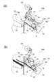
 sheet binding portions 1r of the sheet bundle 1n shown in FIG. 22 on the lower tray 137, and reduces the total height of the sheet bundle 1n after the binding process stacked on the lower tray 137. It can be kept low. In step S21, when the binding process of the final sheet bundle 1n is completed, the job ends.

<マニュアル綴じ>
本実施形態では、中間処理トレイ138上に積載されたシート束1nに対して、綴じ手段となるステイプル部100Aにより綴じ処理可能なマニュアル綴じを有する。図3に示す搬送手段となる搬送パス126によるシート搬送方向とは異なる方向からマニュアル(ユーザの手作業)で中間処理トレイ138上(中間積載手段の上)にシート束1nを載置可能である。
<Manual binding>
In the present embodiment, the sheet bundle 1n stacked on the intermediate processing tray 138 has manual binding that can be bound by the staple unit 100A serving as a binding unit. The sheet bundle 1n can be placed on the intermediate processing tray 138 (on the intermediate stacking unit) manually (by the user's manual operation) from a direction different from the sheet conveying direction by the conveying path 126 serving as the conveying unit shown in FIG. .

本実施形態のマニュアル綴じは、図16及び図17に示すように、綴じ手段となるステイプル部100Aのダイ604とスライド支持板605との間に形成される間口内から綴じ処理後のシート束1nをマニュアル(ユーザの手作業)で移動可能である。積載手段となる下トレイ137へ向かう方向と直交するフィニッシャ100本体(シート処理装置本体)の手前方向に移動可能である。   As shown in FIGS. 16 and 17, the manual binding according to the present embodiment is a sheet bundle 1n after the binding process from the inside formed between the die 604 of the staple unit 100A serving as the binding means and the slide support plate 605. Can be moved manually (manual operation by the user). It can move in the forward direction of the finisher 100 main body (sheet processing apparatus main body) orthogonal to the direction toward the lower tray 137 serving as a stacking means.

本実施形態の綴じ手段となるステイプル部100Aは、フィニッシャ100本体(シート処理装置本体)の手前側であって、マニュアル綴じを行なうときと、前述したオート綴じを行なうときとで同位置に配置される。   The stapling unit 100A serving as the binding means of the present embodiment is on the near side of the finisher 100 main body (sheet processing apparatus main body), and is disposed at the same position when performing manual binding and when performing the automatic binding described above. The

図16及び図17を用いてマニュアル綴じ時におけるフィニッシャ100の動作について説明する。図16はステイプル部100Aの構成を示す平面説明図、図17はステイプル部100Aの構成を示す斜視説明図である。   The operation of the finisher 100 during manual binding will be described with reference to FIGS. FIG. 16 is an explanatory plan view showing the configuration of the staple unit 100A, and FIG. 17 is an explanatory perspective view showing the configuration of the staple unit 100A.

図1に示す操作部501でマニュアル綴じが選択されると、先ず、前整合板340がマニュアル綴じ位置に移動する。図16及び図17に示すように、ユーザが綴じ処理を実行したいシート束1nをフィニッシャ100本体の手前側から外装カバー7に設けられたスリット11内に挿入する。   When manual binding is selected by the operation unit 501 shown in FIG. 1, first, the front alignment plate 340 is moved to the manual binding position. As shown in FIGS. 16 and 17, the sheet bundle 1n that the user wants to execute the binding process is inserted into the slit 11 provided in the exterior cover 7 from the front side of the finisher 100 main body.

本実施形態では、マニュアル綴じにおいて、フィニッシャ100本体(シート処理装置本体)の手前側に設けられた予め移動済の整合手段となる前整合板340の外側背面部は以下の通りである。   In the present embodiment, in manual binding, the outer rear surface portion of the front alignment plate 340 serving as alignment means that has been moved in advance provided on the front side of the finisher 100 main body (sheet processing apparatus main body) is as follows.

スリット11内にシート束1nが挿入される。綴じ手段となるステイプル部100Aのダイ604とスライド支持板605との間に形成される間口内からシート束1nの挿入方向の該シート束1nの奥側の突き当てガイド(ストッパ)として前整合板340の外側背面部が機能する。シート束1nの挿入方向は積載手段となる下トレイ137へ向かう方向と直交する方向である。これにより綴じ処理前のシート束1nの位置を確定させることが出来る。   A sheet bundle 1 n is inserted into the slit 11. A front alignment plate as an abutment guide (stopper) on the back side of the sheet bundle 1n in the insertion direction of the sheet bundle 1n from the front opening formed between the die 604 of the staple unit 100A serving as a binding means and the slide support plate 605 The outer back side of 340 functions. The insertion direction of the sheet bundle 1n is a direction orthogonal to the direction toward the lower tray 137 serving as a stacking unit. As a result, the position of the sheet bundle 1n before the binding process can be determined.

図1に示す操作部501により綴じ処理実行ボタンを押すことで、シート束1nは片側コーナー部の綴じ処理が施される。綴じ処理されたシート束1nは、綴じ処理実行前にスリット11内に挿入した方向と逆方向にユーザによって抜き取られる。   By pressing a binding process execution button using the operation unit 501 shown in FIG. 1, the sheet bundle 1n is subjected to a binding process at one corner. The bound sheet bundle 1n is extracted by the user in the direction opposite to the direction in which the sheet bundle 1n is inserted into the slit 11 before the binding process is executed.

これによりマニュアル綴じ時の綴じ処理ジョブは完了する。続けて次の綴じ処理を実行したい場合は、同様のシート束1nの挿入動作と綴じ処理の実行を繰り返す。これにより継続して複数のシート束1nの綴じ処理が可能になる。   Thus, the binding processing job at the time of manual binding is completed. If it is desired to continue the next binding process, the insertion operation of the same sheet bundle 1n and the execution of the binding process are repeated. As a result, it is possible to continuously bind a plurality of sheet bundles 1n.

前述したように、ステイプラ132のダイ604とスライド支持板605とを以下の形状で構成した。シート束1nを半抜きポンチ601により切削して形成した半抜き舌状片1pの先端部1p1を折り返す。そして、該シート束1nをスリットポンチ602により切削して形成したスリット1s内に挿し込む。   As described above, the die 604 and the slide support plate 605 of the stapler 132 are configured as follows. The tip 1p1 of the half-cut tongue-like piece 1p formed by cutting the sheet bundle 1n with the half-punch punch 601 is folded back. Then, the sheet bundle 1 n is inserted into a slit 1 s formed by cutting with a slit punch 602.

シート束1nの綴じ処理後に部分的にシート束1nのシート面1n1から外側に突出した挿し込み綴じ部1rが形成される。挿し込み綴じ部1rを起点として、ダイ604と、スライド支持板605とに下トレイ137へ向かう方向と、シート1の幅方向とにそれぞれ延伸させた凹部604c,605dを形成する。   After the binding process of the sheet bundle 1n, an insertion binding portion 1r that protrudes outward from the sheet surface 1n1 of the sheet bundle 1n is formed. Starting from the insertion binding portion 1r, recesses 604c and 605d are formed in the die 604 and the slide support plate 605 so as to extend in the direction toward the lower tray 137 and in the width direction of the sheet 1, respectively.

これによりシート束1nの綴じ処理後に部分的に突出した挿し込み綴じ部1rが綴じ処理後のシート束1nの移動時に上下のガイドとなるダイ604と、スライド支持板605とに引っかかることが無い。シート束1nの綴じ処理後に部分的に突出した挿し込み綴じ部1rは凹部604c,605d内を容易に移動することが可能となる。   Accordingly, the insertion binding part 1r partially protruding after the binding process of the sheet bundle 1n is not caught by the die 604 serving as the upper and lower guides and the slide support plate 605 when the sheet bundle 1n after the binding process is moved. The insertion binding portion 1r partially protruding after the binding processing of the sheet bundle 1n can easily move in the recesses 604c and 605d.

これにより綴じ処理後のシート束1nを下トレイ137へ向かう方向へ搬送する移動動作が容易に実行出来る。更に、図15(b)に示すように、下トレイ137上に複数のシート束1nを互い違いにソートして積載するための該シート束1nの幅方向(図15(b)の左右方向)へ搬送する移動動作が容易に実行出来る。   As a result, the moving operation of conveying the sheet bundle 1n after the binding process in the direction toward the lower tray 137 can be easily executed. Further, as shown in FIG. 15B, in the width direction of the sheet bundle 1n for stacking and stacking a plurality of sheet bundles 1n on the lower tray 137 (in the left-right direction in FIG. 15B). The carrying operation can be easily executed.

更に、図16及び図17に示すように、ユーザがマニュアル綴じ処理するためにフィニッシャ100の手前方向へ綴じ処理後のシート束1nを移動する動作が容易に出来る。このように綴じ処理後のシート束1nを異なる複数の方向へ容易に移動させることが出来る。   Further, as shown in FIGS. 16 and 17, the user can easily move the sheet bundle 1n after the binding process toward the front side of the finisher 100 for the manual binding process. In this way, the sheet bundle 1n after the binding process can be easily moved in a plurality of different directions.

これにより綴じ処理後のシート束1nの抜き取り性を向上させるためにステイプラ132を回転移動させる必要がない。また、シート束1nのシフト積載を実施するために下トレイ137を移動させる等してフィニッシャ100の大型化やコストアップが生じることが無い。これにより簡易な構成で、針無し綴じのマニュアル綴じ処理やソート積載が可能となった。   Accordingly, it is not necessary to rotate and move the stapler 132 in order to improve the pullability of the sheet bundle 1n after the binding process. Further, there is no increase in the size and cost of the finisher 100 by moving the lower tray 137 in order to carry out the shift stacking of the sheet bundle 1n. As a result, it is possible to perform manual binding processing and sort stacking with needleless binding with a simple configuration.

本実施形態では、ステイプラ132を固定して、綴じ処理後のシート束1nを移動させた。しかし、シート束1nをステイプラ132から抜き取る方法としては、ステイプラ132をシート束1nに対して移動させる構成としても同様の効果が得られる。   In the present embodiment, the stapler 132 is fixed, and the sheet bundle 1n after the binding process is moved. However, as a method of extracting the sheet bundle 1n from the stapler 132, the same effect can be obtained even if the stapler 132 is moved with respect to the sheet bundle 1n.

本実施形態では、綴じ処理後のシート束1nをステイプラ132に対して移動させることが可能である。このためシート束1nに対して綴じ部位を変えながら一箇所のみならず、複数の綴じ箇所を設けることも可能となる。   In the present embodiment, the sheet bundle 1n after the binding process can be moved with respect to the stapler 132. For this reason, it is possible to provide not only one location but also a plurality of binding locations while changing the binding location for the sheet bundle 1n.

本実施形態のステイプラ132は、ダイ604とスライド支持板605との両方に凹部604c,605dをそれぞれ形成してシート束1nの挿し込み綴じ部1rが通過する間隔を広げている。他に、図20(a),(b)に示すように、片側のダイ604またはスライド支持板605に凹部604c,605dを適宜形成することでも同様の効果を得ることが出来る。   In the stapler 132 of this embodiment, recesses 604c and 605d are formed in both the die 604 and the slide support plate 605, respectively, to widen the interval through which the insertion binding portion 1r of the sheet bundle 1n passes. In addition, as shown in FIGS. 20A and 20B, the same effect can be obtained by appropriately forming the recesses 604c and 605d in the die 604 or the slide support plate 605 on one side.

本実施形態では、切り込み挿入型の針無し綴じ手段によるオート綴じ処理と、マニュアル綴じ処理に関して、双方の処理がユーザのニーズによって選択可能である。   In the present embodiment, both processing can be selected according to the needs of the user with respect to the automatic binding processing by the cutting insertion type needleless binding means and the manual binding processing.

また、綴じ手段となるステイプラ132による綴じ処理後のシート束nの移動方向として、該ステイプラ132の間口内から綴じ処理後のシート束nを下トレイ137に搬送するオート綴じを行なう。更に、該ステイプラ132の間口内から綴じ処理後のシート束nを下トレイ137へ向かう方向と直交するシート処理装置本体の手前方向に移動可能なマニュアル綴じを行なう。   Further, as the moving direction of the sheet bundle n after the binding process by the stapler 132 serving as the binding means, automatic binding is performed in which the sheet bundle n after the binding process is conveyed from the inside of the stapler 132 to the lower tray 137. Further, manual binding is performed so that the sheet bundle n after binding processing can be moved from the inside of the stapler 132 toward the front side of the sheet processing apparatus main body perpendicular to the direction toward the lower tray 137.

更に、該ステイプラ132の間口内から綴じ処理後のシート束nを下トレイ137へ向かう方向と直交するシート処理装置本体の奥側方向に移動可能なシート束ソートを行なう。これらを選択的に行なうことが出来る。更に、装置を大型化したりコストアップすることなく、操作性、仕分け性、複数箇所綴じといった品質面の向上と、破損防止性等の品質保証の両立を図ることを実現させたシート処理装置を提供することが出来る。   Further, a sheet bundle sorting is performed in which the sheet bundle n after the binding process can be moved from the inside of the stapler 132 toward the lower side of the sheet processing apparatus main body perpendicular to the direction toward the lower tray 137. These can be selectively performed. In addition, we provide a sheet processing device that achieves both quality improvements such as operability, sorting, and multi-point binding, and quality assurance such as breakage prevention without increasing the size and cost of the device. I can do it.

1 …シート
1n …シート束
126 …搬送パス(搬送手段)
132 …ステイプラ(綴じ手段)
138 …中間処理トレイ(中間積載手段)
604 …ダイ(ガイド面)
604c …凹部
605 …スライド支持板(ガイド面)
605d …凹部
1 ... sheet 1n ... sheet bundle
126… Conveying path (conveying means)
132 ... Stapler (binding means)
138 ... Intermediate processing tray (intermediate stacking means)
604 ... Die (guide surface)
604c Recess
605 ... Slide support plate (guide surface)
605d ... recess

Claims (7)

搬送手段によって搬送されたシートが積載される第1積載手段と、
前記第1積載手段のシートを整合する整合手段と、
前記第1積載手段に積載されたシート束に対して一部がシートと連結した状態で切削された半抜き舌状片と、貫通穴からなるスリットとを各シートに形成し、前記シート束の各半抜き舌状片の先端部を前記シート束の各スリットに挿入する処理を処理位置において施すことによって前記シート束の端部を綴じる綴じ手段と、
前記綴じ手段により綴じられたシート束が積載される第2積載手段と、
を有し、
前記搬送手段によって搬送されてきた、前記第1積載手段に積載されたシート束を、前記綴じ手段により綴じる第1綴じ動作と、
前記搬送手段によるシート搬送方向とは異なる方向からマニュアルで前記第1積載手段の上に載置されたシート束を、前記綴じ手段により綴じる第2綴じ動作と、
を行ない、
前記綴じ手段の少なくとも一方のガイド面に、前記処理位置から前記第2積載手段へ向かう方向に延伸された第1の凹部と、前記処理位置から前記第1の凹部の延伸方向とは異なる方向に延伸された第2の凹部と、が設けられたことを特徴とするシート処理装置。
A first stacking unit on which sheets conveyed by the conveying unit are stacked;
Alignment means for aligning sheets of the first stacking means;
A half-cut tongue-like piece cut in a state where a part of the sheet bundle stacked on the first stacking unit is connected to the sheet and a slit made of a through hole are formed on each sheet, and the sheet bundle A binding means for binding the end of the sheet bundle by performing a process of inserting the tip of each half-blanked tongue-like piece into each slit of the sheet bundle at a processing position;
A second stacking unit on which a bundle of sheets bound by the binding unit is stacked;
Have
A first binding operation in which the sheet bundle stacked on the first stacking unit that has been transported by the transporting unit is bound by the binding unit;
A second binding operation for binding the sheet bundle manually placed on the first stacking unit from a direction different from the sheet conveying direction by the conveying unit by the binding unit;
Do
At least one guide surface of said binding means, towards a first recess extending in a direction towards the second stacking unit from the processing position, that is different from the extending direction of the first recess from the processing position a second recess which is oriented to the direction, the sheet processing apparatus characterized by is provided.
搬送手段によって搬送されたシートが積載される第1積載手段と、
前記第1積載手段のシートを整合する整合手段と、
前記第1積載手段に積載されたシート束に対して一部がシートと連結した状態で切削された半抜き舌状片と、貫通穴からなるスリットとを各シートに形成し、前記シート束の各半抜き舌状片の先端部を前記シート束の各スリットに一体的に挿入する処理を処理位置において施すことによって前記シート束の端部を綴じる綴じ手段と、
前記綴じ手段により綴じられたシート束が積載される第2積載手段と、
を有し、
前記綴じ手段の少なくとも一方のガイド面に、前記処理位置から前記第2積載手段へ向かう方向に延伸された第1の凹部と、前記処理位置から前記第2積載手段へ向かう方向と直交する方向に延伸された第2の凹部と、が設けられたことを特徴とするシート処理装置。
A first stacking unit on which sheets conveyed by the conveying unit are stacked;
Alignment means for aligning sheets of the first stacking means;
A half-cut tongue-like piece cut in a state where a part of the sheet bundle stacked on the first stacking unit is connected to the sheet and a slit made of a through hole are formed on each sheet, and the sheet bundle Binding means for binding the end of the sheet bundle by performing a process of integrally inserting the tip of each half-cut tongue piece into each slit of the sheet bundle at a processing position ;
A second stacking unit on which a bundle of sheets bound by the binding unit is stacked;
Have
At least one guide surface of said binding unit, a first recess extending in a direction towards the second stacking unit from the processing position, in a direction perpendicular to the direction towards the second stacking unit from the processing position A sheet processing apparatus , comprising: an elongated second recess .
前記綴じ手段による前記シート束の綴じ処理後に、前記綴じ手段の間口内から前記シート束を移動させる方向が、少なくとも二つ以上の方向を有することを特徴とする請求項1または請求項に記載のシート処理装置。 After the binding process of the sheet bundle by the binding means, the direction for moving the sheet bundle from the frontage of the binding means, according to claim 1 or claim 2 characterized in that it has at least two or more directions Sheet processing equipment. 前記綴じ手段によって綴じられた後の前記シート束を、前記第2積載手段に搬送する動作を行うことができ、
前記綴じ手段の間口内から綴じられた後の前記シート束を前記第2積載手段へ向かう方向と直交する幅方向に移動可能に前記ガイド面はガイドし、
前記綴じ手段の間口内から綴じられた後の前記シート束を前記幅方向に移動することでシート束をソートする動作を行なうことができることを特徴とする請求項1〜のいずれか1項に記載のシート処理装置。
The sheet bundle after being bound by the binding means can be transported to the second stacking means,
The guide surface guides the sheet bundle after being bound from the front end of the binding means so as to be movable in a width direction perpendicular to the direction toward the second stacking means,
To any one of claims 1 to 3, characterized in that it is possible to perform an operation to sort the sheet bundle the sheet bundle after being stapled from the frontage by moving in the width direction of the binding means The sheet processing apparatus according to the description.
前記綴じ手段は、前記第1綴じ動作を行なうときと、前記第2綴じ動作を行なうときととで同じ、シート処理装置の手前側の位置に配置されることを特徴とする請求項1に記載のシート処理装置。   2. The binding device according to claim 1, wherein the binding unit is disposed at a position on the near side of the sheet processing apparatus when performing the first binding operation and when performing the second binding operation. Sheet processing equipment. シート処理装置本体の手前側の前記整合手段の外側背面部を、前記綴じ手段の間口内から前記第2積載手段へ向かう方向と直交する方向のシート束の突き当てガイドとして構成したことを特徴とする請求項1〜のいずれか1項に記載のシート処理装置。 The outer back surface portion of the aligning unit on the front side of the sheet processing apparatus main body is configured as a sheet bundle abutment guide in a direction orthogonal to the direction from the front end of the binding unit toward the second stacking unit. The sheet processing apparatus according to any one of claims 1 to 5 . 請求項1〜のいずれか1項に記載のシート処理装置と、
画像を形成する画像形成手段と、
を有し、
前記シート処理装置は、前記画像形成手段により画像形成されたシートに対して前記シート処理装置によりシート処理を実施することを特徴とする画像形成装置。
The sheet processing apparatus according to any one of claims 1 to 6 ,
An image forming means for forming an image;
Have
The sheet processing apparatus performs sheet processing by the sheet processing apparatus on a sheet on which an image is formed by the image forming unit.
JP2014093864A 2014-04-30 2014-04-30 Sheet processing apparatus and image forming apparatus Expired - Fee Related JP6362082B2 (en)

Priority Applications (2)

Application Number Priority Date Filing Date Title
JP2014093864A JP6362082B2 (en) 2014-04-30 2014-04-30 Sheet processing apparatus and image forming apparatus
US14/693,167 US9833967B2 (en) 2014-04-30 2015-04-22 Sheet processing apparatus and image forming apparatus

Applications Claiming Priority (1)

Application Number Priority Date Filing Date Title
JP2014093864A JP6362082B2 (en) 2014-04-30 2014-04-30 Sheet processing apparatus and image forming apparatus

Publications (3)

Publication Number Publication Date
JP2015209334A JP2015209334A (en) 2015-11-24
JP2015209334A5 JP2015209334A5 (en) 2017-06-08
JP6362082B2 true JP6362082B2 (en) 2018-07-25

Family

ID=54354608

Family Applications (1)

Application Number Title Priority Date Filing Date
JP2014093864A Expired - Fee Related JP6362082B2 (en) 2014-04-30 2014-04-30 Sheet processing apparatus and image forming apparatus

Country Status (2)

Country Link
US (1) US9833967B2 (en)
JP (1) JP6362082B2 (en)

Families Citing this family (6)

* Cited by examiner, † Cited by third party
Publication number Priority date Publication date Assignee Title
JP2018008778A (en) 2016-07-13 2018-01-18 キヤノン株式会社 Sheet processing device
CN108790457B (en) * 2018-06-14 2020-08-11 华北理工大学 Financial affairs voucher finishing device
CN109016964A (en) * 2018-09-11 2018-12-18 国网山东省电力公司烟台供电公司 A kind of invoice receipt storage attachment means
JP7392408B2 (en) * 2019-11-15 2023-12-06 マックス株式会社 electric stapler
JP2022099850A (en) * 2020-12-23 2022-07-05 富士フイルムビジネスイノベーション株式会社 Binding device, binding member, and image formation system
US11738958B2 (en) * 2021-04-27 2023-08-29 Fujifilm Business Innovation Corp. Recording material processing apparatus and image forming system

Family Cites Families (20)

* Cited by examiner, † Cited by third party
Publication number Priority date Publication date Assignee Title
JPS495960B1 (en) * 1968-03-29 1974-02-09
JP4019605B2 (en) * 2000-05-12 2007-12-12 富士ゼロックス株式会社 Perforation processing apparatus and image forming system using the same
JP5142658B2 (en) 2006-10-26 2013-02-13 キヤノン株式会社 Bookbinding apparatus and image forming apparatus provided with the same
JP4926646B2 (en) 2006-10-26 2012-05-09 キヤノン株式会社 Bookbinding apparatus and image forming apparatus provided with bookbinding apparatus
JP4906616B2 (en) * 2007-07-12 2012-03-28 キヤノン株式会社 Sheet processing apparatus and image forming apparatus
JP2009018932A (en) * 2007-07-13 2009-01-29 Kyocera Mita Corp Sheet post-processing device
JP5509449B2 (en) * 2008-11-12 2014-06-04 コクヨ株式会社 Binding machine
JP5528099B2 (en) 2009-01-26 2014-06-25 キヤノン株式会社 Sheet post-processing apparatus and image forming apparatus having the same
JP5464962B2 (en) 2009-10-07 2014-04-09 キヤノン株式会社 Sheet processing apparatus and image forming system
JP5465139B2 (en) 2009-10-07 2014-04-09 キヤノン株式会社 Sheet processing apparatus and image forming system
JP5377210B2 (en) 2009-10-07 2013-12-25 キヤノン株式会社 Sheet processing apparatus, image forming apparatus, and image forming system
JP5310606B2 (en) * 2010-03-10 2013-10-09 富士ゼロックス株式会社 Image forming system and paper processing apparatus
JP5056918B2 (en) 2010-07-20 2012-10-24 富士ゼロックス株式会社 Paper processing apparatus and image forming apparatus
JP5464096B2 (en) * 2010-08-03 2014-04-09 富士ゼロックス株式会社 Recording material post-processing apparatus and image forming system
JP5402876B2 (en) * 2010-08-23 2014-01-29 富士ゼロックス株式会社 Recording material post-processing apparatus and image forming system
JP5295326B2 (en) 2011-07-20 2013-09-18 キヤノン株式会社 Sheet processing apparatus and image forming apparatus
JP5995564B2 (en) * 2012-07-11 2016-09-21 キヤノン株式会社 Sheet processing apparatus and image forming apparatus
JP2014073910A (en) 2012-07-11 2014-04-24 Canon Inc Sheet processing device and image formation device
JP6202878B2 (en) * 2013-05-09 2017-09-27 キヤノン株式会社 Sheet material binding apparatus and image forming system
US9387717B2 (en) 2013-08-30 2016-07-12 Canon Kabushiki Kaisha Sheet processing apparatus and image forming apparatus with rotary member to convey sheets

Also Published As

Publication number Publication date
US9833967B2 (en) 2017-12-05
JP2015209334A (en) 2015-11-24
US20150314626A1 (en) 2015-11-05

Similar Documents

Publication Publication Date Title
JP6362082B2 (en) Sheet processing apparatus and image forming apparatus
JP4429219B2 (en) Sheet processing apparatus and image forming apparatus provided with the apparatus
US8162306B2 (en) Sheet aligning apparatus, sheet processing apparatus, and image forming apparatus
US9381658B2 (en) Sheet processing apparatus and image forming apparatus
JP6360368B2 (en) Sheet processing apparatus, image forming apparatus including the same, and sheet additional folding method
JP2009113923A (en) Sheet discharge apparatus, sheet processing apparatus, and image forming apparatus
JP5925157B2 (en) Sheet stacking apparatus, sheet processing apparatus, and image forming apparatus
JP2009126592A (en) Sheet stacking apparatus, sheet processing apparatus and image forming apparatus
US20100187742A1 (en) Sheet post-processing apparatus and image forming apparatus having the same
US8622378B2 (en) Sheet processing apparatus and image forming apparatus
JP5991761B2 (en) Sheet processing apparatus and image forming apparatus
US9139396B2 (en) Sheet processing apparatus and image forming apparatus
JP5888020B2 (en) Paper processing apparatus and image forming system
JP2016030680A (en) Sheet processing device
JP4143626B2 (en) Sheet material processing apparatus and image forming apparatus
JP2015209335A (en) Sheet processing device
JP2007261702A (en) Sheet processing device and image forming device
US20080303200A1 (en) Image forming system
JP2013043750A (en) Paper processing apparatus and image forming system
JP2010159102A (en) Sheet processing device and image forming device
JP4977635B2 (en) Paper processing apparatus and image forming apparatus
JP2008184310A (en) Sheet cutting device, and image forming device
JP2005247450A (en) Sheet treating device and image forming device
JP6021413B2 (en) Sheet stacking apparatus and image forming apparatus
JP5506862B2 (en) Sheet discharging apparatus, sheet processing apparatus, and image forming apparatus

Legal Events

Date Code Title Description
A521 Request for written amendment filed

Free format text: JAPANESE INTERMEDIATE CODE: A523

Effective date: 20170421

A621 Written request for application examination

Free format text: JAPANESE INTERMEDIATE CODE: A621

Effective date: 20170421

A977 Report on retrieval

Free format text: JAPANESE INTERMEDIATE CODE: A971007

Effective date: 20171215

A131 Notification of reasons for refusal

Free format text: JAPANESE INTERMEDIATE CODE: A131

Effective date: 20180116

A521 Request for written amendment filed

Free format text: JAPANESE INTERMEDIATE CODE: A523

Effective date: 20180309

TRDD Decision of grant or rejection written
A01 Written decision to grant a patent or to grant a registration (utility model)

Free format text: JAPANESE INTERMEDIATE CODE: A01

Effective date: 20180522

A61 First payment of annual fees (during grant procedure)

Free format text: JAPANESE INTERMEDIATE CODE: A61

Effective date: 20180619

R151 Written notification of patent or utility model registration

Ref document number: 6362082

Country of ref document: JP

Free format text: JAPANESE INTERMEDIATE CODE: R151

LAPS Cancellation because of no payment of annual fees