JP6202878B2 - Sheet material binding apparatus and image forming system - Google Patents
Sheet material binding apparatus and image forming system Download PDFInfo
- Publication number
- JP6202878B2 JP6202878B2 JP2013099202A JP2013099202A JP6202878B2 JP 6202878 B2 JP6202878 B2 JP 6202878B2 JP 2013099202 A JP2013099202 A JP 2013099202A JP 2013099202 A JP2013099202 A JP 2013099202A JP 6202878 B2 JP6202878 B2 JP 6202878B2
- Authority
- JP
- Japan
- Prior art keywords
- sheet material
- binding
- material bundle
- bundle
- sheet
- Prior art date
- Legal status (The legal status is an assumption and is not a legal conclusion. Google has not performed a legal analysis and makes no representation as to the accuracy of the status listed.)
- Expired - Fee Related
Links
Images


Classifications
-
- B—PERFORMING OPERATIONS; TRANSPORTING
- B65—CONVEYING; PACKING; STORING; HANDLING THIN OR FILAMENTARY MATERIAL
- B65H—HANDLING THIN OR FILAMENTARY MATERIAL, e.g. SHEETS, WEBS, CABLES
- B65H43/00—Use of control, checking, or safety devices, e.g. automatic devices comprising an element for sensing a variable
- B65H43/02—Use of control, checking, or safety devices, e.g. automatic devices comprising an element for sensing a variable detecting, or responding to, absence of articles
-
- B—PERFORMING OPERATIONS; TRANSPORTING
- B65—CONVEYING; PACKING; STORING; HANDLING THIN OR FILAMENTARY MATERIAL
- B65H—HANDLING THIN OR FILAMENTARY MATERIAL, e.g. SHEETS, WEBS, CABLES
- B65H37/00—Article or web delivery apparatus incorporating devices for performing specified auxiliary operations
- B65H37/04—Article or web delivery apparatus incorporating devices for performing specified auxiliary operations for securing together articles or webs, e.g. by adhesive, stitching or stapling
-
- B—PERFORMING OPERATIONS; TRANSPORTING
- B31—MAKING ARTICLES OF PAPER, CARDBOARD OR MATERIAL WORKED IN A MANNER ANALOGOUS TO PAPER; WORKING PAPER, CARDBOARD OR MATERIAL WORKED IN A MANNER ANALOGOUS TO PAPER
- B31F—MECHANICAL WORKING OR DEFORMATION OF PAPER, CARDBOARD OR MATERIAL WORKED IN A MANNER ANALOGOUS TO PAPER
- B31F5/00—Attaching together sheets, strips or webs; Reinforcing edges
- B31F5/001—Attaching together sheets, strips or webs; Reinforcing edges by stapling or riveting
-
- B—PERFORMING OPERATIONS; TRANSPORTING
- B42—BOOKBINDING; ALBUMS; FILES; SPECIAL PRINTED MATTER
- B42B—PERMANENTLY ATTACHING TOGETHER SHEETS, QUIRES OR SIGNATURES OR PERMANENTLY ATTACHING OBJECTS THERETO
- B42B4/00—Permanently attaching together sheets, quires or signatures by discontinuous stitching with filamentary material, e.g. wire
-
- B—PERFORMING OPERATIONS; TRANSPORTING
- B42—BOOKBINDING; ALBUMS; FILES; SPECIAL PRINTED MATTER
- B42B—PERMANENTLY ATTACHING TOGETHER SHEETS, QUIRES OR SIGNATURES OR PERMANENTLY ATTACHING OBJECTS THERETO
- B42B9/00—Devices common to machines for carrying out the processes according to more than one of the preceding main groups
-
- B—PERFORMING OPERATIONS; TRANSPORTING
- B42—BOOKBINDING; ALBUMS; FILES; SPECIAL PRINTED MATTER
- B42C—BOOKBINDING
- B42C1/00—Collating or gathering sheets combined with processes for permanently attaching together sheets or signatures or for interposing inserts
- B42C1/12—Machines for both collating or gathering and permanently attaching together the sheets or signatures
-
- B—PERFORMING OPERATIONS; TRANSPORTING
- B65—CONVEYING; PACKING; STORING; HANDLING THIN OR FILAMENTARY MATERIAL
- B65H—HANDLING THIN OR FILAMENTARY MATERIAL, e.g. SHEETS, WEBS, CABLES
- B65H2301/00—Handling processes for sheets or webs
- B65H2301/10—Selective handling processes
- B65H2301/16—Selective handling processes of discharge in bins, stacking, collating or gathering
- B65H2301/1635—Selective handling processes of discharge in bins, stacking, collating or gathering selective stapling modes, e.g. corner or edge or central
-
- B—PERFORMING OPERATIONS; TRANSPORTING
- B65—CONVEYING; PACKING; STORING; HANDLING THIN OR FILAMENTARY MATERIAL
- B65H—HANDLING THIN OR FILAMENTARY MATERIAL, e.g. SHEETS, WEBS, CABLES
- B65H2801/00—Application field
- B65H2801/24—Post -processing devices
- B65H2801/27—Devices located downstream of office-type machines
Landscapes
- Engineering & Computer Science (AREA)
- Mechanical Engineering (AREA)
- Textile Engineering (AREA)
- Folding Of Thin Sheet-Like Materials, Special Discharging Devices, And Others (AREA)
- Paper Feeding For Electrophotography (AREA)
Description
本発明は、画像形成後のシートに後処理を行う後処理装置及び後処理装置を有する画像形成システムに関する。より詳しくは、画像が形成された用紙等のシート材を複数枚束ねたシート材束を綴じる技術に関する。 The present invention relates to a post-processing apparatus that performs post-processing on a sheet after image formation, and an image forming system having the post-processing apparatus. More specifically, the present invention relates to a technique for binding a sheet material bundle in which a plurality of sheet materials such as paper on which an image is formed is bundled.
画像形成システムにおいて、画像形成装置により画像が形成されたシート材に対して種々の後処理を行うための後処理装置が設けられる場合がある。この種の後処理装置として、例えば、複数枚のシート材を束ねたシート材束を、金属針等の綴じ部材を用いて綴じるステイプラを備えたシート材綴じ処理装置が知られている。 In an image forming system, a post-processing device for performing various post-processing on a sheet material on which an image is formed by an image forming device may be provided. As this type of post-processing apparatus, for example, a sheet material binding processing apparatus including a stapler that binds a sheet material bundle formed by binding a plurality of sheet materials using a binding member such as a metal needle is known.
シート材綴じ処理装置では、画像形成装置から排出されたシート材束に、自動的に、ステイプラによる綴じ処理が行われるのが一般的である(「機内ステイプル」)。一方で、機内ステイプルとは別に、ユーザのマニュアル操作により綴じ処理を行いたいというニーズもある(「マニュアルステイプル」)。 In a sheet material binding processing apparatus, a sheet material bundle discharged from an image forming apparatus is generally automatically subjected to a binding process by a stapler (“in-staple stapling”). On the other hand, apart from the in-flight stapling, there is a need to perform a binding process by a user's manual operation (“manual stapling”).
そのようなユーザのニーズに応じるものとして、特許文献1には、ユーザが手動でシート材束を後処理装置の排出口に挿入することにより、ステイプラによる綴じ処理を行う技術が開示されている。
In order to meet such user needs,
しかしながら、上記のようなマニュアルステイプルを行う場合、シート材束が正しい綴じ位置に配置されていない状態で綴じ処理が行われる可能性がある。その場合、シート材束を正しく綴じることができなかった綴じ部材が、シート材綴じ処理装置内に残留することがある。シート材綴じ処理装置内に残留する綴じ部材は、次回の綴じ処理の際にシート材束と一緒にシート材綴じ処理装置内部に押し込まれて、シート材綴じ処理装置の故障の原因となることがある。 However, when performing manual stapling as described above, the binding process may be performed in a state where the sheet material bundle is not arranged at the correct binding position. In that case, the binding member that could not correctly bind the sheet material bundle may remain in the sheet material binding processing apparatus. The binding member remaining in the sheet material binding processing apparatus is pushed into the sheet material binding processing apparatus together with the sheet material bundle at the time of the next binding processing, and may cause a failure of the sheet material binding processing apparatus. is there.
本発明は、上記の問題を解決するために、綴じ部材の残留を回避するシート材綴じ処理装置、及び画像形成システムを提供することを主たる課題とする。 SUMMARY OF THE INVENTION In order to solve the above problems, it is a main object of the present invention to provide a sheet material binding processing apparatus and an image forming system for avoiding a binding member remaining.
上記課題を解決する本発明のシート材綴じ処理装置は、複数枚のシート材を束ねたシート材束が挿入される用紙挿入口と、前記用紙挿入口に挿入された前記シート材束を綴じる綴じ手段と、予め設定された検出時間間隔で前記用紙挿入口の前記シート材束の有無を検出する検出手段と、前記綴じ手段が動作を開始してからの時間を計測するカウンタと、前記検出手段がシート材束有りを検出して前記綴じ手段による前記シート材束への綴じ処理を開始することが決定した後に、前記シート材束への綴じ処理が完了する前に前記検出手段がシート材束無しを検出した場合、前記カウンタが計測した前記時間が予め定められた設定時間未満であれば前記綴じ手段により開始された綴じ処理を完了させることなく前記綴じ処理を停止させ、前記カウンタが計測した前記時間が前記設定時間以上であれば前記綴じ処理を続行させる制御手段と、を備えることを特徴とする。 The sheet material binding processing apparatus of the present invention that solves the above-described problems includes a paper insertion slot into which a sheet material bundle formed by bundling a plurality of sheet materials is inserted, and a binding that binds the sheet material bundle inserted into the paper insertion slot. Means, detecting means for detecting the presence or absence of the sheet material bundle at the paper insertion slot at a preset detection time interval, a counter for measuring a time after the binding means starts operating, and the detecting means After the sheet material bundle is detected and it is determined that the binding process to the sheet material bundle is started by the binding unit, the detection unit performs the sheet material bundle before the binding process to the sheet material bundle is completed. when detecting the absence, the binding process is stopped without completing been stapled initiated by the binding means the time during which the counter is measured is less than the predetermined set time, the count Motor is characterized in that it comprises a control means for Ru is continued the binding process if the time is the set time or more measured.
本発明によれば、用紙挿入口のシート材束の有無を予め設定された検出時間間隔で周期的に検出し、綴じ処理の開始後にシート材束無しを検出した場合に、綴じ処理を完了させることなく停止する。このように、綴じ処理の途中であってもシート材束が無いことを検出した場合に綴じ処理を停止できるために、シート材綴じ処理装置の故障の可能性を減らすことができる。 According to the present invention, the presence or absence of a sheet material bundle at the paper insertion opening is periodically detected at a preset detection time interval, and the binding process is completed when the absence of the sheet material bundle is detected after the binding process is started. Stop without. In this manner, since it is possible to stop the binding process when it is detected that there is no sheet material bundle even during the binding process, the possibility of failure of the sheet material binding processing apparatus can be reduced.
以下、本発明の実施の形態を図面を参照しつつ詳細に説明する。 Hereinafter, embodiments of the present invention will be described in detail with reference to the drawings.
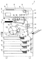
図1は、本実施形態の画像形成システムの全体構成図である。この画像形成システムは、画像形成装置1と、シート材綴じ処理装置50とを含んで構成される。シート材綴じ処理装置50は、画像形成装置1から画像形成後のシート材を受け付け、後処理を行う後処理装置の一例となるものである。画像形成装置1は、シート材綴じ処理装置50との関係では、シート材を供給可能に接続された外部装置の一例となる。
FIG. 1 is an overall configuration diagram of an image forming system according to the present embodiment. The image forming system includes an
<画像形成装置の機構>
画像形成装置1は、原稿画像を読み取る画像読取部2と、シート材に画像を形成する画像形成部3とを有している。本実施形態では、シート材として、用紙Sを用いる。また、画像形成用の色材として、現像剤の一例であるトナーを用いる。
<Mechanism of image forming apparatus>
The
画像読取部2の上部には、透明ガラス板からなる原稿台4が設けられている。ユーザは、原稿台4の所定の位置に、画像面を下向きにして原稿Dを載置した後、原稿圧着板5でこれを押圧固定する。原稿台4の下側には、原稿Dを照明するランプ6と、照明した原稿Dの光像を画像処理ユニット7に導くための反射ミラー8、9、10とを有する光学系が設けられている。ランプ6及び反射ミラー8、9、10は、所定の速度で移動して原稿Dを走査する。
A document table 4 made of a transparent glass plate is provided above the
画像形成部3は、感光体ドラム11、一次帯電ローラ12、ロータリ現像ユニット13、中間転写ベルト14、転写ローラ15、クリーナ16、レーザユニット17、用紙カセット18、定着器19、排出ローラ対21を備える。
一次帯電ローラ12は、レーザ光照射前に感光体ドラム11の表面を均一に帯電する。レーザユニット17は、画像データに基づいて、帯電した感光体ドラム11の表面に光像を照射し、静電潜像を形成する。ロータリ現像ユニット13は、感光体ドラム11の表面に形成された静電潜像に、マゼンタ、シアン、イエロー、ブラックの各色トナーを付着させ、トナー像を形成する。
The
The
ロータリ現像ユニット13は、回転現像方式を採用しており、現像器13K、現像器13Y、現像器13M、現像器13Cを有し、モータ(不図示)により回転可能である。現像器13Kはブラック、現像器13Yはイエロー、現像器13Mはマゼンタ、現像器13Cはシアンを、それぞれ現像するために用いられる。
感光体ドラム11上にモノクロのトナー像を形成するときは、感光体ドラム11と近接する現像位置に現像器13Kが回転移動して現像を行う。同様に、フルカラーのトナー像を形成するときは、ロータリ現像ユニット13の回転により、現像位置に現像器13Y〜13Kが順次配置され、各色について現像を行う。
The rotary developing
When a monochrome toner image is formed on the
感光体ドラム11の表面に現像されたトナー像は、中間転写ベルト14に転写される。クリーナ16は、トナー像転写後の感光体ドラム11に残留したトナーを除去する。転写ローラ15は、中間転写ベルト14のトナー像を、用紙カセット18から供給された用紙Sに転写する。定着器19は、加熱・加圧により、搬送される用紙S上にトナー像を定着させる。定着器19においてトナー像が定着された用紙Sは、排出ローラ対21により、画像形成装置1にとって下流側に設置されたシート材綴じ処理装置50に排出される。
The toner image developed on the surface of the
<シート材綴じ処理装置の機構>
次に、シート材綴じ処理装置50について説明する。シート材綴じ処理装置50は、画像形成装置1から用紙Sが排出される位置に設けられる。シート材綴じ処理装置50は、複数枚の用紙Sを束ねた用紙束(複数枚のシート材を束ねたシート材束の一例)を綴じる綴じ機構、この綴じ機構を移動させる変位機構及びこの変位機構を制御する制御機構とを備える。シート材綴じ処理装置50と画像形成装置1とは、図示しない信号線を介して通信を行うことにより、相互の状態を監視し、協働して動作する。
<Mechanism of sheet material binding processing apparatus>
Next, the sheet material
このシート材綴じ処理装置50は、可動ステイプラ51、エコステイプラ52、マニュアルステイプル用紙挿入口53、マニュアルステイプル用紙検出センサ54、マニュアルステイプル実行ボタン55、用紙検出センサ56、及び用紙整合部57を有している。可動ステイプラ51は、上述した変位機構によりその位置が変位する(移動する)ステイプラである。
The sheet material
可動ステイプラ51及びエコステイプラ52は、用紙Sの有無を検出する用紙検出センサ56が用紙整合部57に排出された用紙Sを検出すると、ユーザが設定した綴じモードに従い、綴じ処理を行う。
可動ステイプラ51は、綴じ部材の一例である針を用いて綴じ処理を行う。エコステイプラ52は、相互に嵌合する上歯部と下歯部を有しており、用紙束を、上歯部と下歯部で挟み加圧することにより、綴じ部材を用いずに綴じ処理を行う。
When the
The
マニュアルステイプル用紙挿入口53は、ユーザが手動で用紙束を挿入するためのものである。マニュアルステイプル用紙検出センサ54は、マニュアルステイプル用紙挿入口53に挿入される用紙束の有無を検出する。マニュアルステイプル用紙検出センサ54が用紙束有りを検出すると、マニュアルステイプル実行ボタン55が押下げ可能状態となる。ユーザがマニュアルステイプル実行ボタン55を押下げることにより、可動ステイプラ51によって、マニュアルステイプル用紙挿入口53に挿入された用紙束に対し、綴じ処理が行われる。
The manual stapling
<可動ステイプラの詳細>
ここで可動ステイプラ51について詳しく説明する。
図2は、シート材綴じ処理装置50を上方から見た断面図である。図2の下側が図1で示した画像形成装置1の前面側となる。可動ステイプラ51は、2つの役割を担っている。1つめは、画像形成装置1から排出された用紙S1の束に対して、予め設定された綴じ位置で自動的に綴じ処理を行う機内ステイプラとしての役割である。2つめは、ユーザによりマニュアルステイプル用紙挿入口53に挿入された用紙S2の束に対して、マニュアル操作で綴じ処理を行うマニュアルステイプラとしての役割である。
<Details of movable stapler>
Here, the
FIG. 2 is a cross-sectional view of the
機内ステイプラとして用いられる場合、可動ステイプラ51は、変位機構の制御により移動経路101に沿って移動し、位置X1〜Xnのうち、ユーザが設定した位置にて綴じ処理を行う。なお、位置X1〜Xnの設定可能数は、シート材綴じ処理装置50の製品仕様によって異なる。
When used as an in-machine stapler, the
マニュアルステイプラとして用いられる場合、可動ステイプラ51は、位置Mにて綴じ処理を行う。マニュアルステイプル用紙挿入口53は、シート材綴じ処理装置50(画像形成装置1)の前面側に設けられている。そのため、可動ステイプラ51は、マニュアルステイプルによる綴じ処理を実行する場合に、変異機構の制御に従い、位置Mに移動する。
なお、可動ステイプラ51は、綴じ処理を行わないときには、位置X0又は位置Mで待機する。
When used as a manual stapler, the
The
<マニュアルステイプル用紙検出センサの配置>
図3は、マニュアルステイプル用紙検出センサ54の配置を説明する図である。
図3はシート材綴じ処理装置50を上から見た断面図である。図3の下側が図1で示した画像形成装置1の前面側となる。
<Arrangement of manual stapling paper detection sensor>
FIG. 3 is a diagram for explaining the arrangement of the manual stapling
FIG. 3 is a cross-sectional view of the
マニュアルステイプル時にマニュアルステイプル用紙挿入口53に挿入された用紙S2は、用紙S2の辺Aに対する突き当て部材401及び辺Aに直交した辺Bに対する突き当て部材402に当接した状態に位置決めされる。可動ステイプラ51は、この位置に位置決めされた用紙束へのマニュアルステイプルによる綴じ処理を行う。
そのために、マニュアルステイプル用紙検出センサ54は、用紙S2が移動可能な方向で確実に用紙S2の有無を検出できる位置に配置される。例えば、図3では、マニュアルステイプル用紙検出センサ54を、用紙S2の辺A及び辺Bの二辺から等しい距離に配置する。つまりマニュアルステイプル用紙検出センサ54は、辺A及び辺Bに対して45度の線上の用紙検出位置403に配置され、用紙S2が辺Aの並行方向又は辺Bの並行方向のどちらに移動しても検出できるようにする。
The paper S2 inserted into the manual stapling
Therefore, the manual stapling
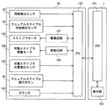
<画像形成システム全体の機能>
図4は、画像形成システムの制御装置の構成図である。
<Functions of the entire image forming system>
FIG. 4 is a configuration diagram of a control device of the image forming system.
シート材綴じ処理装置50の制御は、主としてCPU162により行われる。CPU162は、画像形成装置1を制御する制御装置、例えばCPU161と通信を行うことにより、お互いの稼働状態を検知(あるいは判定)する。
用紙検出センサ56は、用紙整合部57(図1参照)における用紙Sの有無を検出し、検出結果をCPU162に通知する。マニュアルステイプル用紙検出センサ54は、マニュアルステイプル用紙挿入口53(図1参照)における用紙Sの有無を検出し、検出結果をCPU162に通知する。ステイプラモータ163は、可動ステイプラ51(図1参照)内に設けられており、可動ステイプラ51を駆動して、綴じ処理を実行する。駆動回路167は、ステイプラモータ163を制御する。可動ステイプラ移動モータ164は、ステッピングモータであり、可動ステイプラ位置検出センサ165で検出された距離に応じて出力駆動パルス数を変えることにより、可動ステイプラ51を任意の位置に移動させる。駆動回路168は、可動ステイプラ移動モータ164を制御する。マニュアルステイプル実行ボタン55は、自己が押下げられたことをCPU162に通知する。マニュアルステイプル実行ボタン55が押下げられることで、用紙束のマニュアルステイプルによる綴じ処理の実行指示がCPU162に入力される。カウンタ180は、マニュアルステイプル実行ボタン55が押下げられてからの時間を計測し、そのカウント値をCPU162に通知する。
画像形成装置1の表示部181は、CPU161又はCPU162から通知されるエラー内容を表示してユーザに報知する。
The control of the sheet material binding
The
The
<マニュアルステイプルによる綴じ処理動作>
マニュアルステイプル時のシート材綴じ処理装置50の制御は、例えば図5のフローチャートで表される手順で行われる。
<Binding operation by manual stapling>
The control of the sheet material binding
用紙束のマニュアルステイプル用紙挿入口53への挿入は、マニュアルステイプル用紙検出センサ54により検出される。そのためにシート材綴じ処理装置50のCPU162は、まず、マニュアルステイプル用紙検出センサ54が用紙束の有無を検出する時間間隔である検出時間間隔t1を1秒に設定する(S101)。CPU162は、マニュアルステイプル用紙検出センサ54が用紙束有り(シート材束有り)を検出するまで、ステップS101を繰り返す(S102:N、S101)。
CPU162は、マニュアルステイプル用紙検出センサ54による用紙束有りの検出により、用紙束がマニュアルステイプル用紙挿入口53に挿入されたと判断して、マニュアルステイプルによる綴じ処理を開始する。
Insertion of a bundle of sheets into the manual stapling
The
CPU162は、マニュアルステイプルによる綴じ処理を開始すると、まず、マニュアルステイプル用紙検出センサ54に設定された検出時間間隔t1を、より短い時間間隔に変更する(S102:Y、S103)。本実施形態では、検出時間間隔t1を0.1ミリ秒に変更する。
When the binding process by manual stapling is started, the
CPU162は、マニュアルステイプル用紙検出センサ54が用紙束有りを検出することでマニュアルステイプルによる綴じ処理を開始するが、開始前は、CPU162の負荷を軽減するために、検出時間間隔t1を1秒に設定する。用紙束有りの検出後、マニュアルステイプルによる綴じ処理を開始することで、CPU162は、検出時間間隔t1を、より短い時間間隔に設定する。用紙束挿入前よりも短い検出時間間隔t1で用紙束の有無を検出することで、用紙束が何らかの要因(落下、ステイプルのやり直し等)でマニュアルステイプル用紙挿入口53から無くなった場合でも、直ちにそのことを検出することができる。
例えば、用紙束が移動速度1000[mm/s]、移動距離1[mm]でマニュアルステイプル用紙検出センサ54の検出範囲内から検出範囲外に移動する場合、移動時間は1ミリ秒になる。そのために、検出時間間隔t1は、1ミリ秒以下に設定する必要がある。本実施形態では、一例として検出時間間隔t1を0.1ミリ秒に設定する。この検出時間間隔では、CPU162の演算負荷を最適化することで、画像形成装置1の能力に影響を与えない。
The
For example, when the sheet bundle moves from the detection range of the manual stapling
検出時間間隔t1の変更後にマニュアルステイプル用紙検出センサ54が用紙束無し(シート材束無し)を検出すると、CPU162は、ステップS101に戻り、検出時間間隔t1を1秒に設定する(S104:N、S101)。
検出時間間隔t1を0.1ミリ秒に変更した後もマニュアルステイプル用紙検出センサ54が用紙束有りを検出する場合、CPU162は、マニュアルステイプルによる綴じ処理を許可する(S104:Y、S105)。マニュアルステイプルによる綴じ処理が許可されると、可動ステイプラ51は、マニュアルステイプルによる綴じ処理を行う位置Mに移動する。CPU162は、マニュアルステイプル実行ボタン55の操作を有効にして、マニュアルステイプル実行ボタン55からの押下げの通知の待機状態になる。
When the manual stapling
If the manual stapling
マニュアルステイプル実行ボタン55が押下げられるまで、CPU162は、マニュアルステイプル用紙検出センサ54による用紙束の有無の検出を繰り返す(S106:N、S104)。
マニュアルステイプル実行ボタン55が押下げられると、CPU162は、カウンタ180のカウント値Tをゼロクリアしてカウントを開始する(S107)。カウント開始後にCPU162は、ステイプラモータ163の駆動を開始する(S108)。
Until the manual
When the manual
ステイプラモータ163の駆動開始後、マニュアルステイプル用紙検出センサ54が用紙束有りを検出している場合に、CPU162はマニュアルステイプルによる綴じ処理を実行する(S109:Y、S110)。CPU162は、綴じ処理の終了後にステイプラモータ163の駆動を停止する(S111)。その後、CPU162は、検出時間間隔t1を1秒に変更してマニュアルステイプルによる綴じ処理を終了する(S112)。
After the
ステイプラモータ163の駆動開始後、マニュアルステイプル用紙検出センサ54が用紙束無しを検出する場合に、CPU162はカウンタ180のカウント値Tを確認する(S109:N、S113)。CPU162は、カウント値Tが設定時間(本実施形態では「0.5秒」)以上であれば、表示部181にエラーを通知してマニュアルステイプルによる綴じ処理を実行する(S113:Y、S114、S110)。ステップS114では、綴じ部材である針がシート材綴じ処理装置50内に残留する可能性があるため、図6(a)に示すように、針を除去する旨のエラー通知を行う。
After the
ステップS109で用紙束無しを検出するということは、一度マニュアルステイプル用紙挿入口53に挿入された用紙束が何らかの要因で無くなったことを表している。「設定時間」については後述するが、これは、マニュアルステイプル実行ボタン55が押下げられてから綴じ部材である針の先端が用紙S2に接触するまでの時間に基づいて決められる値である。そのために、カウント値Tが設定時間以上であれば、針の先端が、すでに用紙束に途中まで押し込まれている。この状態で綴じ処理を中断すると、用紙束をマニュアルステイプル用紙挿入口53から取り出せなくなるため、この場合には、エラーを通知しつつ綴じ処理を実行する。
また、マニュアルステイプルによる綴じ処理としては異常な処理となるために、針がシート材綴じ処理装置50内に残留する可能性もある。残留する針は、次のマニュアルステイプルの際に用紙S2と一緒に押し込まれることがあり、その場合、シート材綴じ処理装置50が故障する可能性がある。そのために、エラーを通知して針の除去をユーザに促すことで、残留する針によるシート材綴じ処理装置50の故障を防止する。
The detection of no sheet bundle in step S109 indicates that the sheet bundle once inserted into the manual stapling
Further, since the binding processing by manual stapling is an abnormal processing, the needle may remain in the sheet material binding
CPU162は、カウント値Tが設定時間(0.5秒)未満であれば、ステイプラモータ163の駆動を停止する(S113:N、S115)。ステイプラモータ163の停止後、CPU162は、ユーザに対して、図6(b)に示すように、綴じ処理が完了していない旨を表示部181に表示する(S116)。その後、CPU162は、検出時間間隔t1を1秒に変更して、マニュアルステイプルによる綴じ処理を終了する(S112)。
カウント値Tが設定時間未満であれば、針の先端は用紙束に接触していない。そのために、この段階でステイプラモータ163の駆動を停止することで綴じ処理を中止し、針がシート材綴じ処理装置50内に残留することを防止する。
If the count value T is less than the set time (0.5 seconds), the
If the count value T is less than the set time, the tip of the needle is not in contact with the sheet bundle. Therefore, at this stage, the driving of the
以上のように、マニュアルステイプルによる綴じ処理を許可した後に用紙束がマニュアルステイプル用紙挿入口53から無くなった場合であっても、綴じ処理を中止する、或いは用紙束が無い状態で綴じ処理を行ったことを通知する。そのために、綴じ処理が行われなかったこと、或いは綴じ部材がシート材綴じ処理装置50内に残留したことを、ユーザが知ることができる。ユーザが残留する綴じ部材を除去することで、シート材綴じ処理装置50の故障を防止することができる。
As described above, even when the sheet bundle is lost from the manual staple
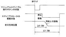
以上の処理のステップS113における「設定時間」について説明する。
図7は、マニュアルステイプル実行ボタン55の押下げからステイプラモータ163の駆動停止までのタイミングを表すタイムチャートである。
The “set time” in step S113 of the above process will be described.
FIG. 7 is a time chart showing the timing from the depression of the manual
マニュアルステイプル実行ボタン55が押下げられると、ステイプラモータ163が駆動する。ステイプラモータ163が駆動されると、綴じ処理が開始されて綴じ部材である針の先端が用紙束に接触する。本実施形態では、ここまでの時間を「0.5秒以上」と想定しており、これに基づいてステップS113の設定時間を「0.5秒」としている。その後、ステイプラモータ163の駆動を停止するまでの時間を「1.5秒以下」と想定している。設定時間は、シート綴じ処理装置50の製品仕様によって異なる。
When the manual
綴じ処理を途中で停止させると、上述の通り、針が用紙束の途中まで押し込まれた状態で停止してしまい、その後、ユーザが用紙S2を取り出すことができなくなる。そのために、用紙S2にステイプラ針が接触した場合(設定時間以上に時間が経過した場合)には、エラーを通知しつつ綴じ処理を行うこととしている(S114、S110)。 When the binding process is stopped halfway, as described above, the needle is stopped halfway through the sheet bundle, and then the user cannot take out the sheet S2. Therefore, when the stapler needle comes into contact with the sheet S2 (when the time exceeds the set time), the binding process is performed while notifying an error (S114, S110).
以上説明したようにシート材綴じ処理装置50に用紙束がある状態を監視し、綴じ処理の途中であっても用紙束が無いことを検出した場合は綴じ処理を停止し、ユーザに通知する。これによりシート綴じ処理装置50の故障の可能性を低減する。
なお、シート綴じ処理装置50は、画像形成装置1の内部に設置する他に、画像形成装置1に併設して使用する自立型のものであってもよい。また、画像形成装置1自体にシート綴じ処理装置50を備えた構成であってもよい。
マニュアルステイプル用紙検出センサ54は、透過型センサ、反射型センタ、フラグタイプセンサ等の用紙S2の有無を検出可能な構成であれば、どのようなタイプのものであってもよい。
As described above, the sheet material binding
Note that the sheet binding
The manual stapling
Claims (14)
前記用紙挿入口に挿入された前記シート材束を綴じる綴じ手段と、
予め設定された検出時間間隔で前記用紙挿入口の前記シート材束の有無を検出する検出手段と、
前記綴じ手段が動作を開始してからの時間を計測するカウンタと、
前記検出手段がシート材束有りを検出して前記綴じ手段による前記シート材束への綴じ処理を開始することが決定した後に、前記シート材束への綴じ処理が完了する前に前記検出手段がシート材束無しを検出した場合、前記カウンタが計測した前記時間が予め定められた設定時間未満であれば前記綴じ手段により開始された綴じ処理を完了させることなく前記綴じ処理を停止させ、前記カウンタが計測した前記時間が前記設定時間以上であれば前記綴じ処理を続行させる制御手段と、を備えることを特徴とする、
シート材綴じ処理装置。 A paper insertion slot into which a bundle of sheet materials in which a plurality of sheet materials are bundled, and
Binding means for binding the sheet material bundle inserted into the paper insertion port;
Detecting means for detecting presence or absence of the sheet material bundle at the paper insertion slot at a preset detection time interval;
A counter for measuring the time from the start of the binding means;
After the detection means detects the presence of the sheet material bundle and decides to start the binding process to the sheet material bundle by the binding means, before the binding process to the sheet material bundle is completed, the detection means When the absence of a sheet material bundle is detected, if the time measured by the counter is less than a predetermined set time, the binding process is stopped without completing the binding process started by the binding unit, and the counter There characterized in that it comprises a control means for Ru is continued the binding process if the time measured is the set time or more,
Sheet material binding processing device.
請求項1記載のシート材綴じ処理装置。 The control means changes the detection time interval after the detection means detects the presence of the sheet material bundle to a time interval shorter than the detection time interval until the detection of the presence of the sheet material bundle. And
The sheet material binding processing apparatus according to claim 1.
前記制御手段は、前記指示手段により前記実行指示が入力されると、前記綴じ処理を開始することを決定することを特徴とする、
請求項1又は2記載のシート材綴じ処理装置。 The operation becomes effective after the detection unit detects the presence of the sheet material bundle, and includes an instruction unit that inputs an instruction to execute the binding process of the sheet material bundle to the control unit by manual operation.
The control means, when the execution instruction is input by the instruction means, determines to start the binding process,
The sheet material binding processing apparatus according to claim 1 or 2 .
請求項3記載のシート材綴じ処理装置。 The set time is determined based on the time from the input of the execution instruction until the leading end of the binding member contacts the sheet material bundle,
The sheet material binding processing apparatus according to claim 3 .
前記制御手段は、前記カウンタが計測した前記時間が前記設定時間以上であれば、前記シート材束を綴じるための綴じ部材を除去することを要求するメッセージを前記表示手段に表示させることを特徴とする、
請求項1〜4のいずれか1項記載のシート材綴じ処理装置。 Having display means for displaying information;
The control means causes the display means to display a message for requesting removal of the binding member for binding the sheet material bundle if the time measured by the counter is equal to or longer than the set time. To
The sheet | seat material binding processing apparatus of any one of Claims 1-4 .
前記制御手段は、前記カウンタが計測した前記時間が前記設定時間未満であれば、前記綴じ処理を停止したことを示すメッセージを前記表示手段に表示させることを特徴とする、
請求項1〜5のいずれか1項記載のシート材綴じ処理装置。 Having display means for displaying information;
If the time measured by the counter is less than the set time, the control means causes the display means to display a message indicating that the binding process has been stopped.
The sheet material binding processing apparatus according to any one of claims 1 to 5 .
前記検出手段は、
前記用紙挿入口に挿入された前記シート材束が前記突き当て部材により位置決めされた状態で、前記シート材束の直交する二辺から等しい距離に配置されることを特徴とする、
請求項1〜6のいずれか1項記載のシート材綴じ処理装置。 The paper insertion opening is provided with an abutting member for positioning when performing the binding process of the inserted sheet material bundle,
The detection means includes
In the state where the sheet material bundle inserted into the paper insertion port is positioned by the abutting member, the sheet material bundle is arranged at an equal distance from two orthogonal sides of the sheet material bundle,
The sheet | seat material binding processing apparatus of any one of Claims 1-6 .
前記画像形成手段により画像が形成された複数枚のシート材を束ねたシート材束が挿入される用紙挿入口と、
前記用紙挿入口に挿入された前記シート材束を綴じる綴じ手段と、
予め設定された検出時間間隔で前記用紙挿入口の前記シート材束の有無を検出する検出手段と、
前記綴じ手段が動作を開始してからの時間を計測するカウンタと、
前記検出手段がシート材束有りを検出して前記綴じ手段による前記シート材束への綴じ処理を開始することが決定した後に、前記シート材束への綴じ処理が完了する前に前記検出手段がシート材束無しを検出した場合、前記カウンタが計測した前記時間が予め定められた設定時間未満であれば前記綴じ手段より開始された綴じ処理を完了させることなく前記綴じ手段の動作を停止させ、前記カウンタが計測した前記時間が前記設定時間以上であれば前記綴じ手段の動作を続行させる制御手段と、を備えることを特徴とする、
画像形成システム。 Image forming means for forming an image on a sheet material;
A sheet insertion slot into which a sheet material bundle obtained by bundling a plurality of sheet materials on which images are formed by the image forming unit;
Binding means for binding the sheet material bundle inserted into the paper insertion port;
Detecting means for detecting presence or absence of the sheet material bundle at the paper insertion slot at a preset detection time interval;
A counter for measuring the time from the start of the binding means;
After the detection means detects the presence of the sheet material bundle and decides to start the binding process to the sheet material bundle by the binding means, before the binding process to the sheet material bundle is completed, the detection means If no sheet material bundle is detected, if the time measured by the counter is less than a predetermined set time, the operation of the binding unit is stopped without completing the binding process started by the binding unit , characterized in that the time during which the counter has measurement and a control means for Ru to continue the operation of said binding means if the set time or more,
Image forming system.
請求項8記載の画像形成システム。 The control means changes the detection time interval after the detection means detects the presence of the sheet material bundle to a time interval shorter than the detection time interval until the detection of the presence of the sheet material bundle. And
The image forming system according to claim 8 .
前記制御手段は、前記指示手段により前記実行指示が入力されると、前記綴じ手段の動作を開始させることを特徴とする、
請求項8又は9記載の画像形成システム。 The operation becomes effective after the detection unit detects the presence of the sheet material bundle, and includes an instruction unit that inputs an instruction to execute the binding process of the sheet material bundle to the control unit by manual operation.
The control means starts the operation of the binding means when the execution instruction is input by the instruction means.
The image forming system according to claim 8 or 9 .
請求項10記載の画像形成システム。 The set time is determined based on the time from the input of the execution instruction until the leading end of the binding member contacts the sheet material bundle,
The image forming system according to claim 10 .
前記制御手段は、前記カウンタが計測した前記時間が前記設定時間以上であれば、前記シート材束を綴じるための綴じ部材を除去することを要求するメッセージを前記表示手段に表示させることを特徴とする、
請求項8〜11のいずれか1項記載の画像形成システム。 Having display means for displaying information;
The control means causes the display means to display a message for requesting removal of the binding member for binding the sheet material bundle if the time measured by the counter is equal to or longer than the set time. To
The image forming system according to claim 8 .
前記制御手段は、前記カウンタが計測した前記時間が前記設定時間未満であれば、前記綴じ処理を停止したことを示すメッセージを前記表示手段に表示させることを特徴とする、
請求項8〜12のいずれか1項記載の画像形成システム。 Having display means for displaying information;
If the time measured by the counter is less than the set time, the control means causes the display means to display a message indicating that the binding process has been stopped.
The image forming system according to claim 8 .
前記検出手段は、
前記用紙挿入口に挿入された前記シート材束が前記突き当て部材により位置決めされた状態で、前記シート材束の直交する二辺から等しい距離に配置されることを特徴とする、
請求項8〜13のいずれか1項記載の画像形成システム。 The paper insertion opening is provided with an abutting member for positioning when performing the binding process of the inserted sheet material bundle,
The detection means includes
In the state where the sheet material bundle inserted into the paper insertion port is positioned by the abutting member, the sheet material bundle is arranged at an equal distance from two orthogonal sides of the sheet material bundle,
The image forming system according to claim 8 .
Priority Applications (3)
| Application Number | Priority Date | Filing Date | Title |
|---|---|---|---|
| JP2013099202A JP6202878B2 (en) | 2013-05-09 | 2013-05-09 | Sheet material binding apparatus and image forming system |
| US14/259,222 US9139397B2 (en) | 2013-05-09 | 2014-04-23 | Sheet binding processing apparatus and image forming system |
| CN201410196774.6A CN104140007B (en) | 2013-05-09 | 2014-05-09 | Thin slice binding process equipment and image formation system |
Applications Claiming Priority (1)
| Application Number | Priority Date | Filing Date | Title |
|---|---|---|---|
| JP2013099202A JP6202878B2 (en) | 2013-05-09 | 2013-05-09 | Sheet material binding apparatus and image forming system |
Publications (3)
| Publication Number | Publication Date |
|---|---|
| JP2014218341A JP2014218341A (en) | 2014-11-20 |
| JP2014218341A5 JP2014218341A5 (en) | 2016-06-23 |
| JP6202878B2 true JP6202878B2 (en) | 2017-09-27 |
Family
ID=51849366
Family Applications (1)
| Application Number | Title | Priority Date | Filing Date |
|---|---|---|---|
| JP2013099202A Expired - Fee Related JP6202878B2 (en) | 2013-05-09 | 2013-05-09 | Sheet material binding apparatus and image forming system |
Country Status (3)
| Country | Link |
|---|---|
| US (1) | US9139397B2 (en) |
| JP (1) | JP6202878B2 (en) |
| CN (1) | CN104140007B (en) |
Families Citing this family (12)
| Publication number | Priority date | Publication date | Assignee | Title |
|---|---|---|---|---|
| JP6215184B2 (en) * | 2013-12-27 | 2017-10-18 | キヤノンファインテックニスカ株式会社 | Binding processing apparatus and image forming apparatus including the same |
| JP6362082B2 (en) * | 2014-04-30 | 2018-07-25 | キヤノン株式会社 | Sheet processing apparatus and image forming apparatus |
| JP6381275B2 (en) | 2014-05-07 | 2018-08-29 | キヤノン株式会社 | Image forming apparatus, control method thereof, and program |
| JP2016108136A (en) * | 2014-12-09 | 2016-06-20 | キヤノン株式会社 | Sheet processing device, image formation system, control method and program |
| JP2016122142A (en) * | 2014-12-25 | 2016-07-07 | キヤノン株式会社 | Sheet processing apparatus, control method of sheet processing apparatus, and program |
| JP6548390B2 (en) * | 2014-12-25 | 2019-07-24 | キヤノン株式会社 | Sheet processing apparatus, control method for sheet processing apparatus, and program |
| CN104985944B (en) * | 2015-06-30 | 2017-02-01 | 安徽工程大学 | Binding device and method |
| CN105620074B (en) * | 2015-11-19 | 2017-04-19 | 河北建筑工程学院 | Automatic test paper stapling machine |
| JP7254491B2 (en) * | 2018-11-29 | 2023-04-10 | キヤノン株式会社 | image forming system |
| JP7254490B2 (en) * | 2018-11-29 | 2023-04-10 | キヤノン株式会社 | Recording material processing device or image forming system |
| US11065904B2 (en) * | 2019-03-15 | 2021-07-20 | Toshiba Tec Kabushiki Kaisha | Image forming system and image forming method |
| JP7354662B2 (en) * | 2019-08-07 | 2023-10-03 | 京セラドキュメントソリューションズ株式会社 | Sheet post-processing device and image forming system equipped with the same |
Family Cites Families (26)
| Publication number | Priority date | Publication date | Assignee | Title |
|---|---|---|---|---|
| US4917366A (en) * | 1986-02-25 | 1990-04-17 | Canon Kabushiki Kaisha | Sheet handling apparatus |
| US4878656A (en) * | 1987-03-20 | 1989-11-07 | Canon Kabushiki Kaisha | Sheet finisher |
| JPS63235257A (en) * | 1987-03-20 | 1988-09-30 | Canon Inc | Post treatment device for sheet |
| JP2671998B2 (en) * | 1988-07-13 | 1997-11-05 | 株式会社リコー | Sheet processing equipment |
| JP2642681B2 (en) * | 1988-08-19 | 1997-08-20 | キヤノン株式会社 | Sheet sorting and binding device |
| JP2871018B2 (en) * | 1990-07-11 | 1999-03-17 | オムロン株式会社 | Automatic stapler for copier |
| US5447297A (en) * | 1992-06-26 | 1995-09-05 | Canon Kabushiki Kaisha | Sheet post-processing apparatus |
| JPH0822156A (en) * | 1994-07-06 | 1996-01-23 | Canon Inc | Image forming system |
| JP3937897B2 (en) | 2002-04-10 | 2007-06-27 | キヤノン株式会社 | Discharge processing apparatus and image forming apparatus |
| JP3950727B2 (en) | 2002-04-10 | 2007-08-01 | キヤノン株式会社 | Discharge processing apparatus and image forming apparatus |
| US6948224B2 (en) * | 2003-05-02 | 2005-09-27 | Gradco (Japan) Ltd | Automatic stapling method and stapler |
| JP4287232B2 (en) * | 2003-09-30 | 2009-07-01 | 京セラミタ株式会社 | Stapling apparatus and image forming apparatus |
| US7407156B2 (en) * | 2005-03-22 | 2008-08-05 | Toshiba Tec Kabushiki Kaisha | Sheet finishing apparatus |
| JP2007062925A (en) * | 2005-08-31 | 2007-03-15 | Konica Minolta Business Technologies Inc | Paper sheet processing device and image forming system |
| JP5438914B2 (en) * | 2008-04-22 | 2014-03-12 | キヤノンファインテック株式会社 | Sheet post-processing device |
| US8226079B2 (en) * | 2009-08-04 | 2012-07-24 | Kabushiki Kaisha Toshiba | Manual stapling mode for sheet finishing apparatus |
| US8246034B2 (en) * | 2009-09-15 | 2012-08-21 | Kabushiki Kaisha Toshiba | Sheet processing apparatus and a sheet processing method |
| JP5310627B2 (en) * | 2010-03-29 | 2013-10-09 | 富士ゼロックス株式会社 | Image forming system |
| JP5546312B2 (en) * | 2010-03-29 | 2014-07-09 | ニスカ株式会社 | Post-processing system |
| JP5634201B2 (en) * | 2010-10-05 | 2014-12-03 | キヤノン株式会社 | Image forming apparatus and stapler |
| JP6091191B2 (en) * | 2012-11-30 | 2017-03-08 | キヤノン株式会社 | Sheet binding processing apparatus and image forming system |
| JP5769696B2 (en) * | 2012-12-26 | 2015-08-26 | 京セラドキュメントソリューションズ株式会社 | Post-processing apparatus and image forming apparatus having the same |
| JP6655863B2 (en) * | 2013-07-12 | 2020-03-04 | キヤノンファインテックニスカ株式会社 | Sheet bundle binding device and image forming system having the same |
| JP6130751B2 (en) * | 2013-07-17 | 2017-05-17 | キヤノンファインテック株式会社 | Sheet conveying apparatus and image forming system provided with the same |
| US9394136B2 (en) * | 2013-07-17 | 2016-07-19 | Canon Finetech Inc. | Sheet bundle binding processing apparatus and image forming system having the same |
| JP6032153B2 (en) * | 2013-08-15 | 2016-11-24 | 富士ゼロックス株式会社 | Post-processing apparatus and image forming apparatus |
-
2013
- 2013-05-09 JP JP2013099202A patent/JP6202878B2/en not_active Expired - Fee Related
-
2014
- 2014-04-23 US US14/259,222 patent/US9139397B2/en not_active Expired - Fee Related
- 2014-05-09 CN CN201410196774.6A patent/CN104140007B/en not_active Expired - Fee Related
Also Published As
| Publication number | Publication date |
|---|---|
| CN104140007B (en) | 2016-11-23 |
| CN104140007A (en) | 2014-11-12 |
| JP2014218341A (en) | 2014-11-20 |
| US20140334901A1 (en) | 2014-11-13 |
| US9139397B2 (en) | 2015-09-22 |
Similar Documents
| Publication | Publication Date | Title |
|---|---|---|
| JP6202878B2 (en) | Sheet material binding apparatus and image forming system | |
| JP6091191B2 (en) | Sheet binding processing apparatus and image forming system | |
| CN100468216C (en) | Image forming apparatus | |
| CN100412716C (en) | Image forming apparatus | |
| US9323205B2 (en) | Sheet binding processing apparatus, image forming system and binding method | |
| JP2015009966A (en) | Image formation device, paper post-processing device and control method | |
| US11046538B2 (en) | Image forming apparatus | |
| JP2015040087A (en) | Sheet material binding process device, image formation system, and sheet material binding process method | |
| KR101972752B1 (en) | Sheet processing apparatus, method for controlling sheet processing apparatus, program and storage medium | |
| JP2014240126A (en) | Sheet material binding processing device and image formation system | |
| US20130108284A1 (en) | Image forming apparatus | |
| EP3159744B1 (en) | Image forming apparatus | |
| JP6164960B2 (en) | Sheet processing apparatus and image forming apparatus | |
| CN102815561B (en) | Sheet material recognition device, image processing system and sheet material recognition methods | |
| JP2015006933A (en) | Recording medium set device and image formation device | |
| JP5510055B2 (en) | Image forming apparatus | |
| CN102285546A (en) | Image forming apparatus | |
| JPH07187446A (en) | Paper conveyance device | |
| US9134669B2 (en) | Image forming apparatus having exposure operation control | |
| CN108732883B (en) | Image forming apparatus with a toner supply device | |
| JP2020050494A (en) | Sheet binder | |
| JP6512409B2 (en) | Fixing device and image forming apparatus provided with the fixing device | |
| JP4535909B2 (en) | Fixing apparatus and image forming apparatus | |
| JPS6088965A (en) | Image forming device | |
| JP2009058813A (en) | Image forming apparatus and its control method |
Legal Events
| Date | Code | Title | Description |
|---|---|---|---|
| A521 | Request for written amendment filed |
Free format text: JAPANESE INTERMEDIATE CODE: A523 Effective date: 20160509 |
|
| A621 | Written request for application examination |
Free format text: JAPANESE INTERMEDIATE CODE: A621 Effective date: 20160509 |
|
| A977 | Report on retrieval |
Free format text: JAPANESE INTERMEDIATE CODE: A971007 Effective date: 20170228 |
|
| A131 | Notification of reasons for refusal |
Free format text: JAPANESE INTERMEDIATE CODE: A131 Effective date: 20170307 |
|
| A521 | Request for written amendment filed |
Free format text: JAPANESE INTERMEDIATE CODE: A523 Effective date: 20170427 |
|
| TRDD | Decision of grant or rejection written | ||
| A01 | Written decision to grant a patent or to grant a registration (utility model) |
Free format text: JAPANESE INTERMEDIATE CODE: A01 Effective date: 20170801 |
|
| A61 | First payment of annual fees (during grant procedure) |
Free format text: JAPANESE INTERMEDIATE CODE: A61 Effective date: 20170829 |
|
| R151 | Written notification of patent or utility model registration |
Ref document number: 6202878 Country of ref document: JP Free format text: JAPANESE INTERMEDIATE CODE: R151 |
|
| LAPS | Cancellation because of no payment of annual fees |