JP7254490B2 - Recording material processing device or image forming system - Google Patents
Recording material processing device or image forming system Download PDFInfo
- Publication number
- JP7254490B2 JP7254490B2 JP2018224155A JP2018224155A JP7254490B2 JP 7254490 B2 JP7254490 B2 JP 7254490B2 JP 2018224155 A JP2018224155 A JP 2018224155A JP 2018224155 A JP2018224155 A JP 2018224155A JP 7254490 B2 JP7254490 B2 JP 7254490B2
- Authority
- JP
- Japan
- Prior art keywords
- recording material
- stapling
- processing
- processing tray
- image forming
- Prior art date
- Legal status (The legal status is an assumption and is not a legal conclusion. Google has not performed a legal analysis and makes no representation as to the accuracy of the status listed.)
- Active
Links
Images


Classifications
-
- B—PERFORMING OPERATIONS; TRANSPORTING
- B65—CONVEYING; PACKING; STORING; HANDLING THIN OR FILAMENTARY MATERIAL
- B65H—HANDLING THIN OR FILAMENTARY MATERIAL, e.g. SHEETS, WEBS, CABLES
- B65H31/00—Pile receivers
- B65H31/30—Arrangements for removing completed piles
- B65H31/3027—Arrangements for removing completed piles by the nip between moving belts or rollers
-
- B—PERFORMING OPERATIONS; TRANSPORTING
- B65—CONVEYING; PACKING; STORING; HANDLING THIN OR FILAMENTARY MATERIAL
- B65H—HANDLING THIN OR FILAMENTARY MATERIAL, e.g. SHEETS, WEBS, CABLES
- B65H37/00—Article or web delivery apparatus incorporating devices for performing specified auxiliary operations
- B65H37/04—Article or web delivery apparatus incorporating devices for performing specified auxiliary operations for securing together articles or webs, e.g. by adhesive, stitching or stapling
-
- B—PERFORMING OPERATIONS; TRANSPORTING
- B65—CONVEYING; PACKING; STORING; HANDLING THIN OR FILAMENTARY MATERIAL
- B65H—HANDLING THIN OR FILAMENTARY MATERIAL, e.g. SHEETS, WEBS, CABLES
- B65H43/00—Use of control, checking, or safety devices, e.g. automatic devices comprising an element for sensing a variable
- B65H43/02—Use of control, checking, or safety devices, e.g. automatic devices comprising an element for sensing a variable detecting, or responding to, absence of articles
-
- G—PHYSICS
- G03—PHOTOGRAPHY; CINEMATOGRAPHY; ANALOGOUS TECHNIQUES USING WAVES OTHER THAN OPTICAL WAVES; ELECTROGRAPHY; HOLOGRAPHY
- G03G—ELECTROGRAPHY; ELECTROPHOTOGRAPHY; MAGNETOGRAPHY
- G03G15/00—Apparatus for electrographic processes using a charge pattern
- G03G15/65—Apparatus which relate to the handling of copy material
- G03G15/6538—Devices for collating sheet copy material, e.g. sorters, control, copies in staples form
- G03G15/6541—Binding sets of sheets, e.g. by stapling, glueing
-
- B—PERFORMING OPERATIONS; TRANSPORTING
- B65—CONVEYING; PACKING; STORING; HANDLING THIN OR FILAMENTARY MATERIAL
- B65H—HANDLING THIN OR FILAMENTARY MATERIAL, e.g. SHEETS, WEBS, CABLES
- B65H2301/00—Handling processes for sheets or webs
- B65H2301/10—Selective handling processes
- B65H2301/16—Selective handling processes of discharge in bins, stacking, collating or gathering
- B65H2301/1635—Selective handling processes of discharge in bins, stacking, collating or gathering selective stapling modes, e.g. corner or edge or central
-
- B—PERFORMING OPERATIONS; TRANSPORTING
- B65—CONVEYING; PACKING; STORING; HANDLING THIN OR FILAMENTARY MATERIAL
- B65H—HANDLING THIN OR FILAMENTARY MATERIAL, e.g. SHEETS, WEBS, CABLES
- B65H2301/00—Handling processes for sheets or webs
- B65H2301/50—Auxiliary process performed during handling process
- B65H2301/51—Modifying a characteristic of handled material
- B65H2301/516—Securing handled material to another material
- B65H2301/5161—Binding processes
- B65H2301/51611—Binding processes involving at least a binding element traversing the handled material, e.g. staple
-
- B—PERFORMING OPERATIONS; TRANSPORTING
- B65—CONVEYING; PACKING; STORING; HANDLING THIN OR FILAMENTARY MATERIAL
- B65H—HANDLING THIN OR FILAMENTARY MATERIAL, e.g. SHEETS, WEBS, CABLES
- B65H2404/00—Parts for transporting or guiding the handled material
- B65H2404/10—Rollers
- B65H2404/14—Roller pairs
- B65H2404/144—Roller pairs with relative movement of the rollers to / from each other
-
- B—PERFORMING OPERATIONS; TRANSPORTING
- B65—CONVEYING; PACKING; STORING; HANDLING THIN OR FILAMENTARY MATERIAL
- B65H—HANDLING THIN OR FILAMENTARY MATERIAL, e.g. SHEETS, WEBS, CABLES
- B65H2407/00—Means not provided for in groups B65H2220/00 – B65H2406/00 specially adapted for particular purposes
- B65H2407/20—Means not provided for in groups B65H2220/00 – B65H2406/00 specially adapted for particular purposes for manual intervention of operator
- B65H2407/21—Manual feeding
-
- B—PERFORMING OPERATIONS; TRANSPORTING
- B65—CONVEYING; PACKING; STORING; HANDLING THIN OR FILAMENTARY MATERIAL
- B65H—HANDLING THIN OR FILAMENTARY MATERIAL, e.g. SHEETS, WEBS, CABLES
- B65H2551/00—Means for control to be used by operator; User interfaces
- B65H2551/20—Display means; Information output means
-
- B—PERFORMING OPERATIONS; TRANSPORTING
- B65—CONVEYING; PACKING; STORING; HANDLING THIN OR FILAMENTARY MATERIAL
- B65H—HANDLING THIN OR FILAMENTARY MATERIAL, e.g. SHEETS, WEBS, CABLES
- B65H2701/00—Handled material; Storage means
- B65H2701/10—Handled articles or webs
- B65H2701/18—Form of handled article or web
- B65H2701/182—Piled package
-
- B—PERFORMING OPERATIONS; TRANSPORTING
- B65—CONVEYING; PACKING; STORING; HANDLING THIN OR FILAMENTARY MATERIAL
- B65H—HANDLING THIN OR FILAMENTARY MATERIAL, e.g. SHEETS, WEBS, CABLES
- B65H2801/00—Application field
- B65H2801/24—Post -processing devices
- B65H2801/27—Devices located downstream of office-type machines
-
- G—PHYSICS
- G03—PHOTOGRAPHY; CINEMATOGRAPHY; ANALOGOUS TECHNIQUES USING WAVES OTHER THAN OPTICAL WAVES; ELECTROGRAPHY; HOLOGRAPHY
- G03G—ELECTROGRAPHY; ELECTROPHOTOGRAPHY; MAGNETOGRAPHY
- G03G2215/00—Apparatus for electrophotographic processes
- G03G2215/00362—Apparatus for electrophotographic processes relating to the copy medium handling
- G03G2215/00535—Stable handling of copy medium
- G03G2215/00717—Detection of physical properties
- G03G2215/00721—Detection of physical properties of sheet position
-
- G—PHYSICS
- G03—PHOTOGRAPHY; CINEMATOGRAPHY; ANALOGOUS TECHNIQUES USING WAVES OTHER THAN OPTICAL WAVES; ELECTROGRAPHY; HOLOGRAPHY
- G03G—ELECTROGRAPHY; ELECTROPHOTOGRAPHY; MAGNETOGRAPHY
- G03G2215/00—Apparatus for electrophotographic processes
- G03G2215/00362—Apparatus for electrophotographic processes relating to the copy medium handling
- G03G2215/00789—Adding properties or qualities to the copy medium
- G03G2215/00822—Binder, e.g. glueing device
- G03G2215/00827—Stapler
Landscapes
- Engineering & Computer Science (AREA)
- Textile Engineering (AREA)
- Mechanical Engineering (AREA)
- Physics & Mathematics (AREA)
- General Physics & Mathematics (AREA)
- Folding Of Thin Sheet-Like Materials, Special Discharging Devices, And Others (AREA)
- Paper Feeding For Electrophotography (AREA)
- Accessory Devices And Overall Control Thereof (AREA)
Description
本発明は、記録材に対してステイプル処理を実行する記録材処理装置、または記録材に対して画像形成を実行する画像形成装置と、画像形成装置から搬送された記録材に対してステイプル処理を実行する後処理装置を有する画像形成システムに関する。 The present invention provides a recording material processing apparatus that performs stapling processing on recording materials, an image forming apparatus that performs image formation on recording materials, and a stapling processing on recording materials conveyed from the image forming apparatus. The present invention relates to an image forming system having a post-processing device for performing.
複写機、プリンタ等の画像形成装置から排出された記録材を受け取り、後処理を実行する後処理装置の中には、受け取った記録材に対してステイプル処理を実行するものがある(以下、この機能を自動ステイプルと呼ぶ)。また、他の後処理装置の中には、ユーザによって装置本体の外部から挿入された記録材に対してステイプル処理を実行するものがある(以下、この機能をマニュアルステイプルと呼ぶ)。 Among post-processing apparatuses that receive recording materials discharged from an image forming apparatus such as a copier or printer and perform post-processing, there are some that perform stapling processing on the received recording materials (hereinafter referred to as this function is called Auto Staple). Further, among other post-processing devices, there is one that executes stapling processing on recording materials inserted from the outside of the device main body by the user (this function is hereinafter referred to as manual stapling).
特許文献1には、自動ステイプルを行うステイプルユニットとマニュアルステイプルを行うステイプルユニットを別々に設けることなく、1つのステイプルユニットによって2つの機能を実現する後処理装置が記載されている。この後処理装置では、自動ステイプルを実行する処理トレイに対し、ユーザが後処理装置の排出口から記録材を挿入してマニュアルステイプルの実行ボタンを押すと、挿入された記録材に対してステイプル処理が実行される。 Japanese Patent Application Laid-Open No. 2002-200002 describes a post-processing device that achieves two functions with one stapling unit without separately providing a stapling unit that performs automatic stapling and a stapling unit that performs manual stapling. In this post-processing device, when a user inserts recording materials from the discharge port of the post-processing device into a processing tray that executes automatic stapling and presses a manual stapling execution button, the inserted recording materials are stapled. is executed.
特許文献2には、自動ステイプルを行う場合に、処理トレイに載置された用紙の位置をガイド部材によって整合する後処理装置が記載されている。この後処理装置では、マニュアルステイプルを行う場合、装置本体の外部から挿入される用紙とガイド部材が干渉しないように、最大用紙サイズに対応した位置にガイド部材を移動させている。 Japanese Patent Application Laid-Open No. 2002-200001 describes a post-processing device that aligns the positions of sheets placed on a processing tray by a guide member when performing automatic stapling. In this post-processing apparatus, when manual stapling is performed, the guide member is moved to a position corresponding to the maximum sheet size so that the guide member does not interfere with the sheets inserted from the outside of the apparatus main body.
しかし、マニュアルステイプルによってステイプル処理が実行される位置は固定されているとは限らない。例えば用紙の角だけでなく、用紙の中央端にステイプル処理が実行されるように、ユーザがステイプラの位置を切り替えることのできる構成も考えられる。さらに、マニュアルステイプルを実行する際に、ユーザが最大サイズよりも小さいサイズの用紙を処理トレイに挿入する場合も考えられる。 However, the position where manual stapling is performed is not always fixed. For example, a configuration is conceivable in which the user can switch the position of the stapler so that stapling is performed not only at the corners of the paper but also at the central edge of the paper. Furthermore, when executing manual stapling, the user may insert paper of a size smaller than the maximum size into the processing tray.
特許文献2の構成によれば、マニュアルステイプルを行う場合、ガイド部材は最大サイズに対応した位置まで移動されるため、最大サイズよりも小さいサイズの用紙を挿入する際には用紙のセット位置に自由度がうまれる。この時、ステイプラの位置に応じた位置に用紙をセットしないと、ユーザが意図しない位置にステイプル処理が実行されてしまう、または空打ちとなってステイプラの針が無駄に消費されてしまう。なお、上記の課題は、1つのステイプルユニットによってマニュアルステイプルのみを実行する後処理装置にも当てはまる。 According to the configuration of Patent Document 2, when manual stapling is performed, the guide member is moved to a position corresponding to the maximum size. The degree is born. At this time, if the paper is not set in a position corresponding to the position of the stapler, the stapling process will be executed at a position not intended by the user, or the staples of the stapler will be wasted due to blank firing. Note that the above problem also applies to a post-processing apparatus that performs only manual stapling with one stapling unit.
本発明の目的は、マニュアルステイプルを実行する際のユーザビリティを向上させ、ユーザの意図した位置にステイプル処理が実行されるようにすることである。 SUMMARY OF THE INVENTION An object of the present invention is to improve usability when performing manual stapling, and to perform stapling at a position intended by a user.
上記の目的を達成するための本発明の記録材処理装置は、記録材が載置される処理トレイと、前記処理トレイに載置された記録材を検知する検知手段と、前記処理トレイに載置された記録材に対してステイプル処理を実行するステイプルユニットと、前記ステイプルユニットによる前記ステイプル処理の実行指示を出すための指示手段と、装置本体の外部から前記処理トレイに挿入された記録材を前記検知手段により検知した状態で、前記指示手段からの前記実行指示を受けると前記ステイプル処理を実行する制御手段と、を有する記録材処理装置において、前記ステイプルユニットの位置を複数の位置の間で切り替える切替手段と、前記複数の位置それぞれに対応する前記処理トレイにおける記録材の載置位置を通知する通知手段と、を有し、前記通知手段は、前記切替手段によって切り替えられた前記ステイプルユニットの位置に応じた前記処理トレイにおける記録材の載置位置を通知し、前記通知手段は、前記処理トレイに載置された記録材の位置を整合する複数の整合部材を含み、前記切替手段によって切り替えられた前記ステイプルユニットの位置に応じて、対応する前記整合部材を記録材の排出方向の下流側に移動させることを特徴とする。 A recording material processing apparatus of the present invention for achieving the above object comprises a processing tray on which a recording material is placed, detection means for detecting the recording material placed on the processing tray, and a recording material placed on the processing tray. a stapling unit for executing stapling processing on the placed recording materials; an instruction means for issuing an instruction to execute the stapling processing by the stapling unit; and a controller for executing the stapling process when receiving the execution instruction from the instructing means in a state detected by the detecting means, wherein the stapling unit is positioned between a plurality of positions. switching means for switching; and notification means for notifying the placement position of the recording material in the processing tray corresponding to each of the plurality of positions; The position of the recording material placed on the processing tray is notified according to the position, and the notification means includes a plurality of alignment members for aligning the position of the recording material placed on the processing tray, and is switched by the switching means. According to the position of the stapling unit, the corresponding aligning member is moved to the downstream side in the ejection direction of the recording material.
また、上記の目的を達成するための本発明の画像形成システムは、記録材に画像を形成する画像形成手段と、前記画像形成手段によって画像が形成された記録材が載置される処理トレイと、前記処理トレイに載置された記録材を検知する検知手段と、前記処理トレイに載置された記録材に対してステイプル処理を実行するステイプルユニットと、前記ステイプルユニットによる前記ステイプル処理の実行指示を出すための指示手段と、前記画像形成手段から前記処理トレイに搬送された記録材に対して前記ステイプル処理を実行する第1のモードと、装置本体の外部から前記処理トレイに挿入された記録材を前記検知手段により検知した状態で、前記実行指示を受けると前記ステイプル処理を実行する第2のモードを切り替え可能な制御手段と、を有する画像形成システムにおいて、前記ステイプルユニットの位置を複数の位置の間で切り替える切替手段と、前記複数の位置それぞれに対応する前記処理トレイにおける記録材の載置位置を通知する通知手段と、を有し、前記通知手段は、前記切替手段によって切り替えられた前記ステイプルユニットの位置に応じた前記処理トレイにおける記録材の載置位置を通知し、前記通知手段は、前記処理トレイに載置された記録材の位置を整合する複数の整合部材を含み、前記切替手段によって切り替えられた前記ステイプルユニットの位置に応じて、対応する前記整合部材を記録材の排出方向の下流側に移動させることを特徴とする。 Further, an image forming system of the present invention for achieving the above object comprises image forming means for forming an image on a recording material, and a processing tray on which the recording material on which an image is formed by the image forming means is placed. a detecting means for detecting recording materials placed on the processing tray; a stapling unit for performing stapling processing on the recording materials placed on the processing tray; and an instruction to execute the stapling processing by the stapling unit. a first mode for executing the stapling process on the recording material conveyed from the image forming means to the processing tray; and a recording medium inserted into the processing tray from outside the apparatus main body. and control means capable of switching a second mode for executing the stapling process when receiving the execution instruction while the material is detected by the detection means, wherein the stapling unit is positioned at a plurality of positions. switching means for switching between positions; and notification means for notifying the placement position of the recording material in the processing tray corresponding to each of the plurality of positions , wherein the notification means is switched by the switching means. Notifying the placement position of the recording material on the processing tray according to the position of the stapling unit, wherein the notification means includes a plurality of aligning members for aligning the positions of the recording materials placed on the processing tray, According to the position of the stapling unit switched by the switching means, the corresponding aligning member is moved downstream in the discharge direction of the recording material.
本発明によれば、マニュアルステイプルを実行する際のユーザビリティを向上させ、ユーザの意図した位置にステイプル処理が実行されるようにすることができる。 According to the present invention, it is possible to improve usability when performing manual stapling, and to perform stapling processing at a position intended by the user.
〔実施例1〕
本実施例では、マニュアルステイプル用の用紙束をセットする位置をユーザに通知する手段として、装置本体に貼り付けられたシールまたは装置本体に形成された刻印を採用した構成について説明する。
[Example 1]
In the present embodiment, as means for notifying the user of the position where the sheet stack for manual stapling is to be set, a configuration employing a seal attached to the apparatus main body or a stamp formed on the apparatus main body will be described.
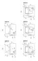
図1は、本実施例における画像形成装置101と後処理装置29(記録材処理装置)を備えた画像形成システム1の構成を示す図である。画像形成装置101は、電子写真方式のカラーレーザービームプリンタである。画像形成装置101は、現像色の数だけ並置されたステーション毎に、アルミシリンダの外周に有機光導伝層を塗布して構成された感光ドラム5Y、5M、5C、5Kを備えている。ここで、Yはイエロー、Mはマゼンタ、Cはシアン、Kはブラックを表し、以下、必要な場合を除き省略する。画像形成装置101は、帯電器7、レーザスキャナ10、現像器8、トナーカートリッジ11、中間転写ベルト12、一次転写ローラ6、二次転写ローラ9、定着器13を備えている。
FIG. 1 is a diagram showing the configuration of an image forming system 1 including an
印刷動作が開始されると、感光ドラム5は、不図示の駆動モータによって反時計回り方向(図中、矢印方向)に回転する。帯電器7は、感光ドラム5を帯電させるために、帯電スリーブ7S(7YS、7MS、7CS、7KS)を有している。帯電スリーブ7Sによって帯電された感光ドラム5の表面は、レーザスキャナ10によって露光される。レーザスキャナ10は入力された画像データに基づいて感光ドラム5を露光し、感光ドラム5に静電潜像を形成する。現像器8は、感光ドラム5に形成された静電潜像を可視化するために、現像スリーブ8S(8YS、8MS、8CS、8CK)を有している。現像スリーブ8Sは感光ドラム5にトナーを供給することで、静電潜像をトナー像として可視化する。 When the printing operation is started, the photosensitive drum 5 is rotated counterclockwise (arrow direction in the drawing) by a driving motor (not shown). The charger 7 has a charging sleeve 7S (7YS, 7MS, 7CS, 7KS) to charge the photosensitive drum 5. As shown in FIG. A laser scanner 10 exposes the surface of the photosensitive drum 5 charged by the charging sleeve 7S. The laser scanner 10 exposes the photosensitive drum 5 based on the input image data to form an electrostatic latent image on the photosensitive drum 5 . The developing device 8 has a developing sleeve 8S (8YS, 8MS, 8CS, 8CK) for visualizing the electrostatic latent image formed on the photosensitive drum 5. As shown in FIG. The developing sleeve 8S supplies toner to the photosensitive drum 5 to visualize the electrostatic latent image as a toner image.
中間転写ベルト12は、駆動ローラ18aと従動ローラ18b、18cによって張設された無端状ベルトである。中間転写ベルト12は、感光ドラム5に当接しつつ、駆動ローラ18aによって時計回り方向(図中、矢印方向)に回転する。そして、中間転写ベルト12には、一次転写ローラ6によって、順次、トナー像が転写される(以下、一次転写という)。各色のトナー像が中間転写ベルト12に重なって転写されることにより、中間転写ベルト12にカラー画像が形成される。
The
給紙カセット2又はマルチトレイ3には用紙P(記録材)が載置されている。給紙ローラ4は給紙カセット2又はマルチトレイ3から搬送路25へ用紙Pを給紙する。搬送路25へ給紙された用紙Pは、搬送ローラ24によってレジストレーションセンサ19へ向けて搬送される。レジストレーションセンサ19が用紙Pの先端を検知すると、用紙Pは更に一定量だけ搬送され、停止しているレジストレーションローラ23に対して突き当てられる。これにより用紙Pには撓み(ループともいう)が形成される。レジストレーションローラ23は中間転写ベルト12に形成されたトナー像とタイミングが合うように、停止している用紙Pを二次転写ローラ9へ向けて再搬送する。用紙Pは、中間転写ベルト12と二次転写ローラ9により狭持搬送され、中間転写ベルト12に形成されたトナー像が一括して用紙Pに転写される(以下、二次転写という)。二次転写を行う場合、二次転写ローラ9は実線で示す位置に移動して中間転写ベルト12に当接するが、二次転写を行わない場合、二次転写ローラ9は点線で示す位置に移動して中間転写ベルト12から離間する。
Paper P (recording material) is placed in the paper feed cassette 2 or the multi-tray 3 . The paper feed roller 4 feeds the paper P from the paper feed cassette 2 or the multi-tray 3 to the
定着器13は、用紙Pを搬送しつつ、転写されたトナー像を用紙Pに定着させる。定着器13は、用紙Pを加熱する定着ローラ14と、用紙Pを定着ローラ14に圧接させる加圧ローラ15を有している。定着ローラ14と加圧ローラ15は中空状に形成され、内部にそれぞれヒータ16、17が配置されている。クリーニング装置21は、中間転写ベルト12に残ったトナーをクリーニングする。クリーニングされたトナーは、クリーニング装置21が有するクリーナ容器に蓄えられる。
The
後処理装置29は、画像形成装置101から排紙された用紙Pを受け取り、受け取った用紙Pに対して後処理を実行する。例えば、受け取った用紙Pを複数の排紙トレイ30、31(排出トレイ)へ仕分けする機能や、ステイプル処理(綴じ処理)を実行して複数枚の用紙Pをまとめる機能などを備えている。用紙Pを排紙トレイ30、31へ仕分けする際は、排紙トレイ30、31の昇降を行うためのモータ(不図示)により、排紙トレイ30、31を上下に移動させる。
The
ステイプル処理に関する構成について詳細に説明する。ステイプルユニット33は、ステイプルトレイ32(処理トレイ)に積載された複数枚の用紙Pに対してステイプル処理を実行する。さらにステイプルユニット33はステイプルカートリッジ34を備えている。ステイプルカートリッジ34にはステイプル処理に使用する針がまとめられている。
A configuration related to stapling will be described in detail. The stapling
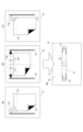
次に、図1と本実施例における後処理装置29の俯瞰図である図2を用いて、画像形成装置101から排紙された用紙Pに対してステイプル処理を実行する場合について説明する。以下、この機能を自動ステイプルと呼ぶ。
Next, a case of stapling sheets P discharged from the
画像形成装置101から後処理装置29に搬送された用紙Pの後端が搬送ローラ対35を通過し、排紙ローラ対36に到達した時点で、排紙ローラ対36と引き込みローラ37を逆回転させ、用紙Pをステイプルトレイ32へと引き込み積載する。予め指定された枚数の用紙Pがステイプルトレイ32に積載された後、排紙ローラ対36と引き込みローラ37を点線の位置へ移動させる。そして、図2(a)に記載された排紙方向に対して直交する方向(幅方向)において移動可能な用紙ガイド43、44を用紙幅に対応する位置と用紙幅より広い位置の間で数回移動させ、ステイプルトレイ32に載置された用紙Pの整合作業を行う。そして、用紙ガイド43、44(整合部材)が用紙幅に対応する位置で停止され、ステイプルユニット33によりステイプル処理が実行される。ステイプルユニット33は図2(c)乃至(e)で示す通り、用紙端に沿って移動することができ、用紙Pの異なる位置にステイプル処理を実行することが可能である。ステイプル処理が実行されると、用紙ガイド43、44は用紙幅よりも広い位置に移動する。そして、ステイプル処理された用紙Pの束は、装置本体42に形成された排紙口41(排出口)を介して、実線の位置へ移動した排紙ローラ対36によって排紙トレイ30又は排紙トレイ31へ排紙される。
When the trailing edge of the paper P conveyed from the
続いて、図1と図2を用いて、ユーザによって装置本体42の外部から挿入された用紙束に対してステイプル処理を行う場合について説明する。以下、この機能をマニュアルステイプルと呼ぶ。
1 and 2, a description will be given of a case where a sheet bundle inserted from the outside of the apparatus
図2(a)、(b)に記載されている通り、後処理装置29には、マニュアルステイプルモード移行ボタン201とマニュアルステイプル実行ボタン202が設置されている(以下、それぞれ移行ボタン201、実行ボタン202と表記する)。また、後処理装置29はステイプルトレイ32に挿入された用紙束203を検知する用紙検知センサ204(記録材検知手段)を備えている。本実施例の後処理装置29は、ユーザが用紙束203を排紙口41からステイプルトレイ32へ挿入することで、マニュアルステイプルが実行される構成となっている。ここで、排紙口41とは、自動ステイプルにおいてステイプル処理された用紙束が排紙トレイ30又は31へ排紙される際に通過する開口であり、外部からも用紙束を挿入可能である。
As shown in FIGS. 2A and 2B, the
マニュアルステイプルを実行する場合、後処理装置29は、ユーザによる移行ボタン201の押下により、マニュアルステイプルモードに移行する。ユーザは移行ボタン201を押下した回数に応じて、図2(c)に示す角綴じ、図2(d)に示す中綴じ、図2(e)に示す角綴じのようにステイプル位置を切り替えることができる。つまり、移行ボタン201はステイプル位置を切り替える切替手段としても機能する。後処理装置29は、マニュアルステイプルモードに移行すると図1の排紙ローラ対36と引き込みローラ37を点線の位置へ移動させる。さらに、用紙ガイド43、44を図2(a)に示す位置から図2(b)に示す最大サイズに対応する位置へと広げる。ここで、最大サイズとは、ステイプルトレイ32に載置可能な用紙Pの中で最大のサイズのことを示す。これにより、ユーザが用紙束203を挿入する際の妨げとならないようにしている。
When executing manual stapling, the
ユーザは装置本体42の外部から排紙口41を介して用紙束203を挿入する。その際、ユーザは選択したステイプル位置に応じたセット位置(載置位置)に用紙束203を挿入する必要がある。図2(c)の角綴じの場合、ユーザは用紙ガイド44に沿って用紙束203を挿入する。挿入された用紙束203は、用紙検知センサ204(記録材検知センサ)によって検知される。用紙検知センサ204が用紙束203を検知すると、ステイプルユニット33が左側のステイプル位置に移動し、後処理装置29はマニュアルステイプルの実行を待機する状態になる。そして、ユーザにより実行ボタン202が押されると、ステイプル処理の実行指示が出され、後処理装置29はステイプルユニット33によるステイプル処理を行う。図2(d)の中綴じの場合、ユーザは用紙ガイド43と44の中央に合わせて用紙束203を挿入する。挿入された用紙束203は、用紙検知センサ204によって検知される。用紙検知センサ204が用紙束203を検知すると、ステイプルユニット33が中央のステイプル位置に移動し、後処理装置29はマニュアルステイプルの実行を待機する状態になる。そして、ユーザにより実行ボタン202が押されると、後処理装置29はステイプルユニット33によるステイプル処理を行う。図2(e)の角綴じの場合、ユーザは用紙ガイド43に沿って用紙束203を挿入する。挿入された用紙束203は、用紙検知センサ204によって検知される。用紙検知センサ204が用紙束203を検知すると、ステイプルユニット33が右側のステイプル位置に移動し、後処理装置29はマニュアルステイプルの実行を待機する状態になる。そして、ユーザにより実行ボタン202が押されると、後処理装置29はステイプルユニット33によるステイプル処理を行う。マニュアルステイプル処理終了後、後処理装置29は、図1の排紙ローラ対36と引き込みローラ37は実線の位置へ移動させ正回転させることで、用紙束203を排紙トレイ30又は31へ排紙させる。このように排紙ローラ対36と引き込みローラ37は、実線の位置と点線の位置の間で移動可能な構成である。
A user inserts the
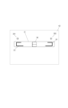
図3は、本実施例におけるマニュアルステイプル用の用紙束203をセットする位置を通知するシールデザインの一例を示す図である。
FIG. 3 is a diagram showing an example of a sticker design for notifying the position where the
図3(a)のシール51は、用紙束203の左上部1ヶ所にステイプル処理が実行される様子を示している。図3(b)のシール52は用紙束203の上部2ヶ所にステイプル処理が実行される様子を示している。図3(c)のシール53は用紙束203の右上部1ヶ所にステイプル処理が実行される様子を示している。図3(d)は後処理装置29を用紙Pの排紙方向の下流側から見た図を示しており、排紙口41が装置本体42に形成されている。排紙口41の上部にあるスペース50にシール51乃至53をそれぞれ貼り付けることで、ユーザに用紙束203のセット位置を通知することができる。シール51乃至53はそれぞれ、ステイプル位置と用紙束203をセットする際に基準となるガイドを示しており、ステイプル位置に応じてどのガイドに沿って用紙束203をセットするかを一目でユーザに示すことが必要である。
A
図2と図3では見る方向が反転しているため、図3(a)に対応する状態が図2(e)、図3(b)に対応する状態が図2(d)、図3(c)に対応する状態が図2(c)となっている。なお、図3(b)のシール52には用紙束203の上部2ヶ所にステイプル処理が実行される用紙が示されているが、図2(d)に対応させて上部1ヶ所にステイプル処理が実行される様子を示してもよい。
2 and 3, the viewing direction is reversed, so the state corresponding to FIG. 3(a) is shown in FIG. The state corresponding to c) is shown in FIG. 2(c). Note that the
図3の破線は説明のための補助線であり、実際のデザインには反映されないものとする。図3(a)、(b)、(c)において、破線部(ア)は用紙束203に対するステイプル位置を示している。破線部(イ)は用紙束203を挿入する際の基準となるガイド(用紙ガイド43または44)を示している。破線部(ウ)は用紙束203を基準となるガイドに寄せてセットするのか(a)、(c)、それとも両側のガイドの中央にセットするのか(b)を示している。
The dashed lines in FIG. 3 are auxiliary lines for explanation and shall not be reflected in the actual design. In FIGS. 3A, 3B, and 3C, the dashed line (A) indicates the stapling position for the stack of
以上より、本実施例によれば、装置本体42にシール51乃至53を貼り付けることで、ユーザが用紙束203をセットする位置を容易に把握することが可能となる。従って、マニュアルステイプルを実行する際のユーザビリティを向上させ、ユーザの意図した位置にステイプル処理が実行されるようにすることができる。
As described above, according to the present embodiment, by attaching the
なお、本実施例では装置本体42にシール51乃至53を貼り付ける構成について説明したが、同様のデザインの刻印を装置本体42に形成してもよい。また、シール51乃至53には、画像だけでなく文字や記号が記載されていてもよい。また、シール51乃至53を貼り付ける位置も図3(d)に示したスペース50に限らない。用紙束203を排紙口41に挿入する際に、ユーザが用紙ガイド43、44とシールまたは刻印を同時に認識できる位置であればかまわない。排紙口41の下部のスペースなどでもよいが、挿入する用紙束203によってシールまたは刻印が隠れてしまう可能性があるため、排紙口41の上部または左右部が望ましい。また、本実施例のデザインは一例であり、本実施例で説明した目的を達成できるのであれば異なるデザインでもよい。
In this embodiment, the structure in which the
〔実施例2〕
本実施例では、マニュアルステイプル用の用紙束をセットする位置をユーザに通知する手段として、装置本体にLEDを設けた構成について説明する。主な部分の説明は実施例1と同様であり、ここでは実施例1と異なる部分のみを説明する。
[Example 2]
In this embodiment, a configuration in which an LED is provided in the apparatus main body as means for notifying the user of the position where the sheet bundle for manual stapling is to be set will be described. The description of the main parts is the same as in the first embodiment, and only the parts different from the first embodiment will be described here.
図4は本実施例における後処理装置29を用紙Pの排紙方向の下流側から見た図を示している。実施例1で説明した図3(d)の構成とは異なり、用紙ガイド43の上部にはLED391が設けられ、用紙ガイド44の上部にはLED392が設けられている。
FIG. 4 shows a view of the
図5は、本実施例における画像形成装置101と後処理装置29のシステム構成を説明するためのブロック図である。コントローラ301は、ホストコンピュータ等の外部機器300と通信を行って印刷データを受信する。また、コントローラ301は画像形成装置101と後処理装置29を統括して制御しており、エンジン制御部302は画像形成装置101を制御し、後処理制御部303は後処理装置29を制御している。304はコントローラ301からエンジン制御部302へ、305はコントローラ301から後処理制御部303へコマンド信号を送信するシリアル信号線である。306はコマンド信号に応えてエンジン制御部302からコントローラ301へ、307は後処理制御部303からコントローラ301へステータスデータを送信するシリアル信号線である。コントローラ301は、エンジン制御部302、後処理制御部303に対し、コマンド信号を送信するとともに、エンジン制御部302、後処理制御部303からのステータスデータを受信することで制御を行っている。このように、複数の装置が接続され動作する場合は、コントローラ301が各装置の制御や状態を一元管理し、各装置間の動作の整合性を保つ。なお、コントローラ301とエンジン制御部302は画像形成装置101に設けられており、後処理制御部303は後処理装置29に設けられている。
FIG. 5 is a block diagram for explaining the system configuration of the
後処理制御部303は、コントローラ301からのコマンド信号に応じて用紙搬送を行う。また、後処理制御部303は自動ステイプルとマニュアルステイプルを切り替えて制御可能である。さらに自動ステイプルを行う場合、後処理制御部303は画像形成装置101から排紙された用紙Pの束に対して、ステイプルユニット33を制御しステイプル処理を行う。また、マニュアルステイプルを行う場合、後処理制御部303は、移行ボタン201が押下された回数に基づき、LED391、392および用紙ガイド43、44を制御する。そして、実行ボタン202、用紙検知センサ204の入力信号に基づいて、ステイプルユニット33を制御しステイプル処理を行う。
A
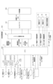
図6は、本実施例における後処理制御部303の詳細図である。後処理制御部303はCPU400を有しており、シリアル通信手段427を介してコントローラ301と通信する。シリアル通信手段427はCPU400とコントローラ301を、シリアル信号線305、307を含む複数の信号線で接続する。外部機器300を通じて印刷データ428がコントローラ301に通知されると、コントローラ301はシリアル通信手段427を介して排紙動作開始信号423等をCPU400に通知する。ここで、排紙動作開始信号423とは、画像形成装置101から後処理装置29に用紙Pが搬送されるタイミングを通知する信号である。また、CPU400はシリアル通信手段427を介して排紙動作ステータス信号425やモード移行信号426等をコントローラ301に通知する。ここで、排紙動作ステータス信号425とは、後処理装置29の内部における用紙Pの処理状態を示す信号である。また、モード移行信号426とは、マニュアルステイプルモードが解除されたことを通知する信号である。
FIG. 6 is a detailed diagram of the
CPU400の出力端子にはモータドライバ410、411が接続される。モータドライバ410は排紙モータ401を駆動する。排紙モータ401が正回転、または、逆回転することにより、排紙ローラ対36と引き込みローラ37を正回転、または、逆回転させることができる。排紙ローラ対36と引き込みローラ37が正回転することで、用紙Pを排紙トレイ30、または、31へ排紙することができ、排紙ローラ対36と引き込みローラ37が逆回転することで、用紙Pをステイプルトレイ32へと引き込むことができる。モータドライバ411は離間モータ402を駆動する。離間モータ402が正回転、または、逆回転することにより、排紙ローラ対36と引き込みローラ37を当接位置、または、離間位置へと移動させることができる。当接位置とは、排紙ローラ対36と引き込みローラ37がステイプルトレイ32に載置されている用紙Pと当接する位置であり、離間位置とは、排紙ローラ対36と引き込みローラ37がステイプルトレイ32に載置されている用紙Pから離間する位置である。用紙検知センサ204は、プルアップ413を使用し、バッファ414を介し、センサ状態(ONの信号またはOFFの信号)をCPU400に入力する。移行ボタン201、実行ボタン202は、ボタンの押下状態(ONの信号またはOFFの信号)をCPU400へ入力する。
CPU400の出力端子には用紙ガイド43および用紙ガイド44のジョガー駆動信号450が、入力端子には用紙ガイド43および用紙ガイド44のジョガーホームポジションセンサ信号451が接続される。ステイプル動作を行う際、CPU400は、ジョガー駆動信号450を介して用紙ガイド43および用紙ガイド44を駆動するジョガーモータ(不図示)を制御してジョガーを開閉させる。そして、ジョガーホームポジションセンサ(不図示)の入力値に応じて、ジョガー駆動信号415を介してジョガーモータを停止させる。また、CPU400の出力端子にはステイプルユニット33のステイプルモータ駆動信号415が、入力端子にはステイプルユニット33のホームポジションセンサ信号416が接続される。ここで、ホームポジションセンサ信号416とは、ステイプラがホームポジションに位置しているか否かを示す信号である。ステイプル動作を行う際、CPU400は、ステイプルモータ駆動信号415を介してステイプルユニット33内のステイプルモータを駆動してステイプル処理を行う。そして、CPU400は、ホームポジションセンサ信号416の入力値に応じて、ステイプルモータ駆動信号415を介してステイプルモータを停止させる。また、CPU400の出力端子にはLED391とLED392が接続される。CPU400は移行ボタン201の押下回数に応じて設定される複数のマニュアルステイプルモードあるいはマニュアルステイプルモードのOFF状態に応じてLED391およびLED392の点灯状態を切り換える。
A jogger drive signal 450 for the paper guides 43 and 44 is connected to the output terminal of the
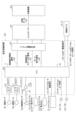
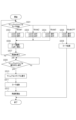
図7は本実施例におけるマニュアルステイプル実行時の後処理制御部303の動作を示すフローチャートである。図7に基づく制御は、後処理制御部303に搭載されたCPU400のROM等に記憶されているプログラムに基づいて実行する。
FIG. 7 is a flow chart showing the operation of the
本フローチャートは、ユーザにより移行ボタン201が押下されることにより開始される。フローチャートを開始すると、まず後処理制御部303は複数あるマニュアルステイプルモードのいずれのモードへ移行したかを判断する(S501)。図2(e)に示すMode1であった場合、後処理制御部303はLED391を点灯させLED392を消灯させる(S502)。図2(d)に示すMode2であった場合、後処理制御部303はLED391とLED392をともに点灯させる(S503)。図2(c)に示すMode3であった場合、後処理制御部303はLED391を消灯させ、LED392を点灯させる(S504)。ModeOFFであった場合、後処理制御部303はLED391とLED392をともに消灯させる(S505)。なお、実施例1でも説明した通り、図2と図4では見る方向が反転しているため、上述したような対応関係となる。
This flowchart is started when the user presses the
Mode1からMode3およびModeOFFは移行ボタン201を押下するたびに順次切り替わる。そしてMode1からMode3の場合、後処理制御部303は排紙ローラ対36と引き込みローラ37をそれぞれ離間させる。そして、ジョガー駆動信号450をONにし、ジョガーホームポジションセンサ信号451がホームポジションを検出してから所定時間後にジョガー駆動信号450をOFFすることにより用紙ガイド43、44を最大幅まで広げる(S506)。これにより、ユーザによる用紙束203の排紙口41への挿入に備える。ModeOFFの場合、後処理制御部303は排紙ローラ対36と引き込みローラ37をそれぞれ当接させ(S508)、マニュアルステイプルモードを終了する。
Mode 1 to Mode 3 and Mode OFF are sequentially switched each time the
S507においてユーザによる用紙束203の挿入を検知した場合、後処理制御部303は、ユーザによる実行ボタン203の押下を待つ(S509)。S509において、ユーザによる実行ボタン203の押下を検知した場合、後処理制御部303はステイプルユニット33によりマニュアルステイプルを実行させる(S510)。そして、排紙ローラ対36と引き込みローラ37を当接させ(S511)、排紙ローラ対36と引き込みローラ37を回転させることでマニュアルステイプル処理済の用紙束203を排紙トレイ30または31へ排出する(S512)。以上で本フローチャートの制御を終了する。
If the user's insertion of the
以上より、本実施例によれば、ユーザが選択したマニュアルステイプルモードに応じて用紙ガイド近辺に配置されたLEDの点灯状況を変更することにより、ユーザはどの用紙ガイドに沿って用紙束を挿入すればよいか判断することができる。従って、マニュアルステイプルを実行する際のユーザビリティを向上させ、ユーザの意図した位置にステイプル処理が実行されるようにすることができる。 As described above, according to this embodiment, by changing the lighting state of the LEDs arranged near the paper guides according to the manual staple mode selected by the user, the user can insert the paper bundle along which paper guide. You can decide if you should. Therefore, it is possible to improve usability when performing manual stapling, and to perform stapling processing at the position intended by the user.
なお、本実施例では基準となる用紙ガイドを示すためにLEDを用いたが、LED以外の発光体でもよい。また、基準となる用紙ガイドそのものに光を照射する構成であってもよい。また、単に発光部を点灯させるだけでなく、点滅させてもよい。 In this embodiment, an LED is used to indicate the reference sheet guide, but a light emitter other than the LED may be used. Alternatively, the light may be applied to the paper guide itself, which serves as a reference. In addition, the light emitting unit may not only light up but also blink.
また、画像形成装置101に取り付けられた画像パネル(不図示)に具体的なイラストを表示することにより、ユーザが選択したマニュアルステイプルモードに応じて、用紙束をセットする基準のガイドを示してもよい。
Further, by displaying a specific illustration on an image panel (not shown) attached to the
〔実施例3〕
本実施例では、マニュアルステイプル用の用紙束をセットする位置をユーザに通知する手段として、用紙ガイドそのものを排紙方向(排出方向)に移動させる方法について説明する。主な部分の説明は実施例1や実施例2と同様であり、ここでは実施例1や実施例2と異なる部分のみを説明する。
[Example 3]
In this embodiment, a method of moving the paper guide itself in the paper discharge direction (discharge direction) as means for notifying the user of the position where the paper stack for manual stapling is to be set will be described. The description of the main parts is the same as in the first and second embodiments, and only the parts that differ from the first and second embodiments will be described here.
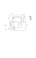
図8は、本実施例における後処理装置29の俯瞰図である。実施例1で説明した図2とは用紙ガイド43および用紙ガイド44の可動範囲が異なる。ユーザによる移行ボタン201の押下により、ユーザが指定したマニュアルステイプルモードに応じて用紙ガイド43および用紙ガイド44を排紙方向に移動させ、ユーザが用紙束203をどちらの用紙ガイドに沿って挿入すべきかを示すことができる。図8では用紙ガイド44を排紙方向に移動させた状態を示している。
FIG. 8 is a bird's-eye view of the
図9は、本実施例における後処理制御部303の詳細図である。実施例2で説明した図6とは、用紙ガイド43を排紙方向に移動させる用紙ガイド駆動信号452と用紙ガイド44を排紙方向に移動させる用紙ガイド駆動信号453がCPU400に接続されている点が異なる。排紙方向移動部45は用紙ガイド駆動信号452や453の信号に従って、用紙ガイド43または44を移動させるメカ機構を示している。CPU400は移行ボタン201の押下回数に応じて設定される複数のマニュアルステイプルモードあるいはマニュアルステイプルモードのOFF状態に応じて用紙ガイド駆動信号452、453をそれぞれ制御する。これにより、用紙ガイド43、44をそれぞれ排紙方向に移動させることができる。
FIG. 9 is a detailed diagram of the
図10は本実施例におけるマニュアルステイプル実行時の後処理制御部303の動作を示すフローチャートである。図10に基づく制御は、後処理制御部303に搭載されたCPU400のROM等に記憶されているプログラムに基づいて実行する。実施例2で説明した図7と異なる部分は、後処理制御部303のマニュアルステイプルモードに応じた制御であるS502からS505の動作と、S512で用紙束排出後に行うS1013の動作である。なお、図10のフローチャートにおいては、図7と差異のあるS1002からS1005とS1013の処理についてのみ説明し、その他の処理に関しては説明を省略する。
FIG. 10 is a flow chart showing the operation of the
ユーザが選択したマニュアルステイプルモードが図2(e)に示すMode1であった場合、後処理制御部303は用紙ガイド43を機外方向に移動させ、用紙ガイド44を移動させない(S1002)。図2(d)に示すMode2であった場合、後処理制御部303は用紙ガイド43と用紙ガイド44をともに機外方向に移動させる(S1003)。図2(c)に示すMode3であった場合、後処理制御部303は用紙ガイド43を移動させず、用紙ガイド44を機外方向に移動させる(S1004)。ModeOFFであった場合、後処理制御部303は用紙ガイド43と用紙ガイド44をともに移動させない(S1005)。また、マニュアルステイプルを行い、用紙束を排出した後、後処理制御部303は、機外方向に移動させた用紙ガイド43または用紙ガイド44を機内方向に移動させ、元の位置に戻す(S1013)。以上で本フローチャートの制御は終了する。
When the manual stapling mode selected by the user is Mode 1 shown in FIG. 2E, the
以上より、本実施例によれば、ユーザが選択したマニュアルステイプルモードに応じて用紙ガイド自体の位置を機外方向と機内方向に独立して移動させることにより、ユーザはどの用紙ガイドに沿って用紙束を挿入すればよいか判断できる。従って、マニュアルステイプルを実行する際のユーザビリティを向上させ、ユーザの意図した位置にステイプル処理が実行されるようにすることができる。 As described above, according to the present embodiment, by independently moving the position of the paper guide itself in the outboard direction and the inboard direction according to the manual stapling mode selected by the user, the user can determine which paper guide to follow. It can be determined whether or not a bundle should be inserted. Therefore, it is possible to improve usability when performing manual stapling, and to perform stapling processing at the position intended by the user.
なお、本実施例では、用紙ガイド43と用紙ガイド44がそれぞれ機外方向(排紙方向)に移動できる構成を例に説明を行ったが、これに限定されない。用紙ガイド43と用紙ガイド44がそれぞれ機内方向に移動できる構成であってもよい。この場合、目立たせる基準となるガイドではない他方のガイドを機内方向に移動させるようにする。また、機外方向にも機内方向にもどちらにも移動できる構成であってもよい。
In this embodiment, a configuration in which the
また、上記の実施例1乃至3においては、移行ボタン201を繰り返し押すことで、マニュアルステイプルモードを切り替える構成について説明した。しかし、これに限定されない。移行ボタン201とは別に、マニュアルステイプルモードを切り替えるためのボタンを別途用意してもよい。
Further, in the first to third embodiments described above, the configuration for switching the manual staple mode by repeatedly pressing the
また、上記の実施例1乃至3において、移行ボタン201や実行ボタン202は後処理装置29に設けられていなくてもよく、画像形成装置101に設けられていてもよい。また、移行ボタン201や実行ボタン202は図2に記載されたような物理的なボタンである必要はなく、ディスプレイなどに表示させた仮想的なボタンであってもよい。
Further, in the first to third embodiments described above, the
また、上記の実施例1乃至3において、移行ボタン201のように後処理装置29の動作モードを切り替える手段を後処理装置29に設ける必要はなく、例えば、外部機器300から後処理装置29の動作モードを切り替えることができる構成であってもよい。
Further, in the first to third embodiments, it is not necessary to provide the
また、上記の実施例1乃至3においては、レーザビームプリンタの例を示したが、本発明を適用する画像形成装置はこれに限られるものではなく、インクジェットプリンタ等、他の印刷方式のプリンタ、又は複写機でもよい。 Further, in the first to third embodiments described above, an example of a laser beam printer is shown, but the image forming apparatus to which the present invention is applied is not limited to this. Or it may be a copier.
29 後処理装置
32 ステイプルトレイ
33 ステイプルユニット
51、52、53 シール
201 マニュアルステイプルモード移行ボタン
202 マニュアルステイプル実行ボタン
204 用紙検知センサ
303 後処理制御部
29
Claims (9)
前記処理トレイに載置された記録材を検知する検知手段と、
前記処理トレイに載置された記録材に対してステイプル処理を実行するステイプルユニットと、
前記ステイプルユニットによる前記ステイプル処理の実行指示を出すための指示手段と、
装置本体の外部から前記処理トレイに挿入された記録材を前記検知手段により検知した状態で、前記指示手段からの前記実行指示を受けると前記ステイプル処理を実行する制御手段と、を有する記録材処理装置において、
前記ステイプルユニットの位置を複数の位置の間で切り替える切替手段と、
前記複数の位置それぞれに対応する前記処理トレイにおける記録材の載置位置を通知する通知手段と、を有し、
前記通知手段は、前記切替手段によって切り替えられた前記ステイプルユニットの位置に応じた前記処理トレイにおける記録材の載置位置を通知し、
前記通知手段は、前記処理トレイに載置された記録材の位置を整合する複数の整合部材を含み、前記切替手段によって切り替えられた前記ステイプルユニットの位置に応じて、対応する前記整合部材を記録材の排出方向の下流側に移動させることを特徴とする記録材処理装置。 a processing tray on which recording materials are placed;
a detecting means for detecting the recording material placed on the processing tray;
a stapling unit that performs stapling processing on the recording materials placed on the processing tray;
an instruction unit for issuing an instruction to execute the stapling process by the stapling unit;
recording material processing comprising: control means for executing the stapling process upon receiving the execution instruction from the instruction means in a state in which the detection means detects the recording material inserted into the processing tray from the outside of the apparatus main body. in the device,
switching means for switching the position of the staple unit between a plurality of positions;
a notification means for notifying the placement position of the recording material in the processing tray corresponding to each of the plurality of positions ;
the notifying means notifying the placement position of the recording material on the processing tray according to the position of the stapling unit switched by the switching means;
The notification means includes a plurality of aligning members for aligning the positions of the recording materials placed on the processing tray, and according to the position of the stapling unit switched by the switching means, the corresponding aligning members are recorded. A recording material processing apparatus, characterized in that it is moved downstream in the discharge direction of the recording material .
前記複数の発光部は、前記切替手段によって切り替えられた前記ステイプルユニットの位置に応じて、発光する発光部が変わり、発光する発光部が変わることで、装置本体の外部から前記処理トレイに挿入される記録材を前記処理トレイのいずれに載置するかをガイドすることを特徴とする請求項1に記載の記録材処理装置。 The notification means includes a plurality of light emitting units arranged on the processing tray,
According to the position of the staple unit switched by the switching means, the plurality of light-emitting units emit light and change the light-emitting unit to emit light. 2. The recording material processing apparatus according to claim 1, wherein the recording material processing apparatus guides which of the processing trays the recording material to be placed is placed.
前記画像形成手段によって画像が形成された記録材が載置される処理トレイと、
前記処理トレイに載置された記録材を検知する検知手段と、
前記処理トレイに載置された記録材に対してステイプル処理を実行するステイプルユニットと、
前記ステイプルユニットによる前記ステイプル処理の実行指示を出すための指示手段と、
前記画像形成手段から前記処理トレイに搬送された記録材に対して前記ステイプル処理を実行する第1のモードと、装置本体の外部から前記処理トレイに挿入された記録材を前記検知手段により検知した状態で、前記実行指示を受けると前記ステイプル処理を実行する第2のモードを切り替え可能な制御手段と、を有する画像形成システムにおいて、
前記ステイプルユニットの位置を複数の位置の間で切り替える切替手段と、
前記複数の位置それぞれに対応する前記処理トレイにおける記録材の載置位置を通知する通知手段と、を有し、
前記通知手段は、前記切替手段によって切り替えられた前記ステイプルユニットの位置に応じた前記処理トレイにおける記録材の載置位置を通知し、
前記通知手段は、前記処理トレイに載置された記録材の位置を整合する複数の整合部材を含み、前記切替手段によって切り替えられた前記ステイプルユニットの位置に応じて、対応する前記整合部材を記録材の排出方向の下流側に移動させることを特徴とする画像形成システム。 an image forming means for forming an image on a recording material;
a processing tray on which a recording material on which an image is formed by the image forming means is placed;
a detecting means for detecting the recording material placed on the processing tray;
a stapling unit that performs stapling processing on the recording materials placed on the processing tray;
an instruction unit for issuing an instruction to execute the stapling process by the stapling unit;
a first mode in which the stapling is performed on the recording material conveyed from the image forming means to the processing tray; and a control means capable of switching a second mode for executing the stapling process when receiving the execution instruction in a state of the image forming system,
switching means for switching the position of the staple unit between a plurality of positions;
a notification means for notifying the placement position of the recording material in the processing tray corresponding to each of the plurality of positions ;
the notifying means notifying the placement position of the recording material on the processing tray according to the position of the stapling unit switched by the switching means;
The notification means includes a plurality of aligning members for aligning the positions of the recording materials placed on the processing tray, and according to the position of the stapling unit switched by the switching means, the corresponding aligning members are recorded. An image forming system characterized in that it is moved downstream in the material discharge direction .
前記排出手段によって排出された記録材が載置される排出トレイと、を有し、
前記装置本体の外部から前記排出口を介して前記処理トレイに記録材を挿入可能であることを特徴とする請求項4または5に記載の画像形成システム。 a discharge means for discharging the recording material stapled by the stapling unit from the processing tray through a discharge port;
a discharge tray on which the recording material discharged by the discharge means is placed;
6. The image forming system according to claim 4 , wherein a recording material can be inserted into the processing tray from the outside of the apparatus main body through the discharge port.
前記制御手段は、前記第1のモードに切り替わった場合、前記ローラを前記当接位置へと移動させ、前記第2のモードに切り替わった場合、前記ローラを前記離間位置へと移動させることを特徴とする請求項6に記載の画像形成システム。 The ejecting means is a roller that can move between a contact position that contacts the recording material placed on the processing tray and a separation position that is separated from the recording material placed on the processing tray,
The control means moves the roller to the contact position when switching to the first mode, and moves the roller to the separation position when switching to the second mode. 7. The image forming system according to claim 6 .
前記複数の発光部は、前記切替手段によって切り替えられた前記ステイプルユニットの位置に応じて、発光する発光部が変わり、発光する発光部が変わることで、装置本体の外部から前記処理トレイに挿入される記録材を前記処理トレイのいずれに載置するかをガイドすることを特徴とする請求項4に記載の画像形成システム。 The notification means includes a plurality of light emitting units arranged on the processing tray,
According to the position of the staple unit switched by the switching means, the plurality of light-emitting units emit light and change the light-emitting unit to emit light. 5. The image forming system according to claim 4 , wherein the image forming system guides which of the processing trays the recording material to be placed is placed.
Priority Applications (5)
| Application Number | Priority Date | Filing Date | Title |
|---|---|---|---|
| JP2018224155A JP7254490B2 (en) | 2018-11-29 | 2018-11-29 | Recording material processing device or image forming system |
| US16/688,940 US11066267B2 (en) | 2018-11-29 | 2019-11-19 | Recording material processing apparatus or image forming system each of which executes stapling process |
| US17/348,628 US11472659B2 (en) | 2018-11-29 | 2021-06-15 | Recording material processing apparatus or image forming system each of which executes stapling process |
| US17/823,425 US11713207B2 (en) | 2018-11-29 | 2022-08-30 | Recording material processing apparatus or image forming system each of which executes stapling process |
| US18/331,872 US11958709B2 (en) | 2018-11-29 | 2023-06-08 | Recording material processing apparatus or image forming system each of which executes stapling process |
Applications Claiming Priority (1)
| Application Number | Priority Date | Filing Date | Title |
|---|---|---|---|
| JP2018224155A JP7254490B2 (en) | 2018-11-29 | 2018-11-29 | Recording material processing device or image forming system |
Publications (3)
| Publication Number | Publication Date |
|---|---|
| JP2020083598A JP2020083598A (en) | 2020-06-04 |
| JP2020083598A5 JP2020083598A5 (en) | 2022-01-06 |
| JP7254490B2 true JP7254490B2 (en) | 2023-04-10 |
Family
ID=70851145
Family Applications (1)
| Application Number | Title | Priority Date | Filing Date |
|---|---|---|---|
| JP2018224155A Active JP7254490B2 (en) | 2018-11-29 | 2018-11-29 | Recording material processing device or image forming system |
Country Status (2)
| Country | Link |
|---|---|
| US (4) | US11066267B2 (en) |
| JP (1) | JP7254490B2 (en) |
Families Citing this family (1)
| Publication number | Priority date | Publication date | Assignee | Title |
|---|---|---|---|---|
| JP2022187326A (en) * | 2021-06-07 | 2022-12-19 | 株式会社リコー | Post-processing device and image forming system |
Citations (3)
| Publication number | Priority date | Publication date | Assignee | Title |
|---|---|---|---|---|
| JP2015003811A (en) | 2013-06-21 | 2015-01-08 | 京セラドキュメントソリューションズ株式会社 | Image forming apparatus and sheet processing device |
| JP2017193416A (en) | 2016-04-21 | 2017-10-26 | 株式会社東芝 | Sheet post-processing device |
| JP2018118804A (en) | 2017-01-23 | 2018-08-02 | 京セラドキュメントソリューションズ株式会社 | Sheet processing apparatus and image forming apparatus |
Family Cites Families (13)
| Publication number | Priority date | Publication date | Assignee | Title |
|---|---|---|---|---|
| US4917366A (en) * | 1986-02-25 | 1990-04-17 | Canon Kabushiki Kaisha | Sheet handling apparatus |
| US4878656A (en) * | 1987-03-20 | 1989-11-07 | Canon Kabushiki Kaisha | Sheet finisher |
| JPH07157179A (en) * | 1993-12-02 | 1995-06-20 | Fuji Xerox Co Ltd | Sheet handling device |
| JPH0986016A (en) * | 1995-09-21 | 1997-03-31 | Canon Inc | Electronic machinery |
| JP2003081521A (en) | 2001-09-17 | 2003-03-19 | Canon Inc | Sheet post-treatment device |
| JP2005206298A (en) | 2004-01-21 | 2005-08-04 | Canon Inc | Sheet post-processing device and image forming device |
| US7407156B2 (en) | 2005-03-22 | 2008-08-05 | Toshiba Tec Kabushiki Kaisha | Sheet finishing apparatus |
| US8226079B2 (en) * | 2009-08-04 | 2012-07-24 | Kabushiki Kaisha Toshiba | Manual stapling mode for sheet finishing apparatus |
| US8146908B2 (en) * | 2009-08-04 | 2012-04-03 | Kabushiki Kaisha Toshiba | Stapling unit, sheet finishing apparatus, and stapling method |
| JP6202878B2 (en) * | 2013-05-09 | 2017-09-27 | キヤノン株式会社 | Sheet material binding apparatus and image forming system |
| JP6141128B2 (en) * | 2013-07-11 | 2017-06-07 | キヤノンファインテック株式会社 | Sheet bundle binding processing apparatus and image forming system using the same |
| US9567183B2 (en) * | 2013-12-16 | 2017-02-14 | Canon Finetech Inc. | Sheet processing apparatus and image forming system having the same |
| JP6215184B2 (en) * | 2013-12-27 | 2017-10-18 | キヤノンファインテックニスカ株式会社 | Binding processing apparatus and image forming apparatus including the same |
-
2018
- 2018-11-29 JP JP2018224155A patent/JP7254490B2/en active Active
-
2019
- 2019-11-19 US US16/688,940 patent/US11066267B2/en active Active
-
2021
- 2021-06-15 US US17/348,628 patent/US11472659B2/en active Active
-
2022
- 2022-08-30 US US17/823,425 patent/US11713207B2/en active Active
-
2023
- 2023-06-08 US US18/331,872 patent/US11958709B2/en active Active
Patent Citations (3)
| Publication number | Priority date | Publication date | Assignee | Title |
|---|---|---|---|---|
| JP2015003811A (en) | 2013-06-21 | 2015-01-08 | 京セラドキュメントソリューションズ株式会社 | Image forming apparatus and sheet processing device |
| JP2017193416A (en) | 2016-04-21 | 2017-10-26 | 株式会社東芝 | Sheet post-processing device |
| JP2018118804A (en) | 2017-01-23 | 2018-08-02 | 京セラドキュメントソリューションズ株式会社 | Sheet processing apparatus and image forming apparatus |
Also Published As
| Publication number | Publication date |
|---|---|
| US11713207B2 (en) | 2023-08-01 |
| US11958709B2 (en) | 2024-04-16 |
| JP2020083598A (en) | 2020-06-04 |
| US20200172369A1 (en) | 2020-06-04 |
| US20220411222A1 (en) | 2022-12-29 |
| US20210309483A1 (en) | 2021-10-07 |
| US11066267B2 (en) | 2021-07-20 |
| US11472659B2 (en) | 2022-10-18 |
| US20230331508A1 (en) | 2023-10-19 |
Similar Documents
| Publication | Publication Date | Title |
|---|---|---|
| JP7224891B2 (en) | Recording material processor | |
| JP7490837B2 (en) | Image forming system | |
| US8115961B2 (en) | Method and apparatus providing consistent rotation for pages in a job in accordance with post-processing requirements | |
| JP6929692B2 (en) | Aftertreatment device | |
| US11958709B2 (en) | Recording material processing apparatus or image forming system each of which executes stapling process | |
| JP6525596B2 (en) | Image forming system, image forming apparatus and post-processing apparatus | |
| US10370216B2 (en) | Image forming apparatus | |
| JP7305341B2 (en) | image forming system | |
| JP7277130B2 (en) | image forming system | |
| JP2001249597A (en) | System and method for forming image | |
| JP7254491B2 (en) | image forming system | |
| JP2001215858A (en) | Printer and image forming method in the printer | |
| JP7527849B2 (en) | Aftertreatment Device | |
| JP5311747B2 (en) | Image forming apparatus and paper discharge processing apparatus | |
| JP2021187645A (en) | Post-processing device | |
| JP7205093B2 (en) | Recording material processing device and image forming system | |
| JP2001242760A (en) | Post treatment device for paper sheet, image forming device, and image forming method | |
| JP2016188119A (en) | Sheet post-processing device and image formation system having the same | |
| JP5151406B2 (en) | Image forming apparatus and program | |
| JP2003160272A (en) | Image forming device | |
| JP2005263334A (en) | Sheet post-processing device | |
| JP2001246790A (en) | Imaging system and imaging method |
Legal Events
| Date | Code | Title | Description |
|---|---|---|---|
| A521 | Request for written amendment filed |
Free format text: JAPANESE INTERMEDIATE CODE: A523 Effective date: 20211124 |
|
| A621 | Written request for application examination |
Free format text: JAPANESE INTERMEDIATE CODE: A621 Effective date: 20211124 |
|
| A977 | Report on retrieval |
Free format text: JAPANESE INTERMEDIATE CODE: A971007 Effective date: 20221005 |
|
| A131 | Notification of reasons for refusal |
Free format text: JAPANESE INTERMEDIATE CODE: A131 Effective date: 20221011 |
|
| A521 | Request for written amendment filed |
Free format text: JAPANESE INTERMEDIATE CODE: A523 Effective date: 20221206 |
|
| TRDD | Decision of grant or rejection written | ||
| A01 | Written decision to grant a patent or to grant a registration (utility model) |
Free format text: JAPANESE INTERMEDIATE CODE: A01 Effective date: 20230228 |
|
| A61 | First payment of annual fees (during grant procedure) |
Free format text: JAPANESE INTERMEDIATE CODE: A61 Effective date: 20230329 |
|
| R151 | Written notification of patent or utility model registration |
Ref document number: 7254490 Country of ref document: JP Free format text: JAPANESE INTERMEDIATE CODE: R151 |