JP5377210B2 - Sheet processing apparatus, image forming apparatus, and image forming system - Google Patents

Sheet processing apparatus, image forming apparatus, and image forming system Download PDF

Info

Publication number
JP5377210B2
JP5377210B2 JP2009233000A JP2009233000A JP5377210B2 JP 5377210 B2 JP5377210 B2 JP 5377210B2 JP 2009233000 A JP2009233000 A JP 2009233000A JP 2009233000 A JP2009233000 A JP 2009233000A JP 5377210 B2 JP5377210 B2 JP 5377210B2
Authority
JP
Japan
Prior art keywords
booklet
thickness
unit
sheet
top portion
Prior art date
Legal status (The legal status is an assumption and is not a legal conclusion. Google has not performed a legal analysis and makes no representation as to the accuracy of the status listed.)
Expired - Fee Related
Application number
JP2009233000A
Other languages
Japanese (ja)
Other versions
JP2011079213A5 (en
JP2011079213A (en
Inventor
賢一 林
潔 渡邊
Current Assignee (The listed assignees may be inaccurate. Google has not performed a legal analysis and makes no representation or warranty as to the accuracy of the list.)
Canon Inc
Original Assignee
Canon Inc
Priority date (The priority date is an assumption and is not a legal conclusion. Google has not performed a legal analysis and makes no representation as to the accuracy of the date listed.)
Filing date
Publication date
Application filed by Canon Inc filed Critical Canon Inc
Priority to JP2009233000A priority Critical patent/JP5377210B2/en
Priority to US12/890,189 priority patent/US8231120B2/en
Publication of JP2011079213A publication Critical patent/JP2011079213A/en
Publication of JP2011079213A5 publication Critical patent/JP2011079213A5/ja
Application granted granted Critical
Publication of JP5377210B2 publication Critical patent/JP5377210B2/en
Expired - Fee Related legal-status Critical Current
Anticipated expiration legal-status Critical

Links

Images

Classifications

    • BPERFORMING OPERATIONS; TRANSPORTING
    • B42BOOKBINDING; ALBUMS; FILES; SPECIAL PRINTED MATTER
    • B42CBOOKBINDING
    • B42C13/00Bookbinding presses; Joint-creasing equipment for bookbinding; Drying or setting devices for books
    • BPERFORMING OPERATIONS; TRANSPORTING
    • B65CONVEYING; PACKING; STORING; HANDLING THIN OR FILAMENTARY MATERIAL
    • B65HHANDLING THIN OR FILAMENTARY MATERIAL, e.g. SHEETS, WEBS, CABLES
    • B65H45/00Folding thin material
    • B65H45/12Folding articles or webs with application of pressure to define or form crease lines
    • B65H45/30Folding in combination with creasing, smoothing or application of adhesive
    • GPHYSICS
    • G03PHOTOGRAPHY; CINEMATOGRAPHY; ANALOGOUS TECHNIQUES USING WAVES OTHER THAN OPTICAL WAVES; ELECTROGRAPHY; HOLOGRAPHY
    • G03GELECTROGRAPHY; ELECTROPHOTOGRAPHY; MAGNETOGRAPHY
    • G03G15/00Apparatus for electrographic processes using a charge pattern
    • G03G15/65Apparatus which relate to the handling of copy material
    • G03G15/6555Handling of sheet copy material taking place in a specific part of the copy material feeding path
    • G03G15/6573Feeding path after the fixing point and up to the discharge tray or the finisher, e.g. special treatment of copy material to compensate for effects from the fixing
    • BPERFORMING OPERATIONS; TRANSPORTING
    • B65CONVEYING; PACKING; STORING; HANDLING THIN OR FILAMENTARY MATERIAL
    • B65HHANDLING THIN OR FILAMENTARY MATERIAL, e.g. SHEETS, WEBS, CABLES
    • B65H2701/00Handled material; Storage means
    • B65H2701/10Handled articles or webs
    • B65H2701/13Parts concerned of the handled material
    • B65H2701/132Side portions
    • B65H2701/1321Side portions of folded article or web
    • B65H2701/13212Fold, spine portion of folded article
    • GPHYSICS
    • G03PHOTOGRAPHY; CINEMATOGRAPHY; ANALOGOUS TECHNIQUES USING WAVES OTHER THAN OPTICAL WAVES; ELECTROGRAPHY; HOLOGRAPHY
    • G03GELECTROGRAPHY; ELECTROPHOTOGRAPHY; MAGNETOGRAPHY
    • G03G2215/00Apparatus for electrophotographic processes
    • G03G2215/00362Apparatus for electrophotographic processes relating to the copy medium handling
    • G03G2215/00919Special copy medium handling apparatus
    • G03G2215/00936Bookbinding

Abstract

A sheet processing apparatus includes a holding portion that nips and holds a booklet, which includes folded sheets, by a pair of holding members opposite to each other; and a pressing portion that enters a gap between the pair of holding members, wherein the pressing portion presses the spine of the held booklet so as to deform the spine of the booklet; wherein the pressing portion has plurality of pressing members, each having a different thickness in the thickness direction of the booklet, and the pressing member capable of entering the gap between the pair of holding members, and having the thickness closest to the thickness of the booklet which is nipped and held by the pair of holding members is selected among the plurality of pressing members so as to perform the deforming process.

Description

本発明は、折り畳まれたシート束からなる冊子の折り頂部を変形処理するシート処理装置、画像形成装置、及び画像形成システムに関する。   The present invention relates to a sheet processing apparatus, an image forming apparatus, and an image forming system for deforming a folded top portion of a booklet composed of folded sheet bundles.

従来、概略20枚以上のシートからなるシート束を一括で折り畳むと、折り頂部付近が湾曲を有するような仕上がりの冊子となる。このように折り畳まれたシート束からなる冊子の折りは不十分であり、折り畳んでもすぐに開いてしまい、見栄えの良くない外観を呈する。この様な冊子では平担な状態で載置することができないため、多数の冊子を積み重ねることが困難となっていた。   Conventionally, when a sheet bundle composed of approximately 20 sheets or more is folded at a time, a finished booklet having a curved portion near the top of the fold is obtained. The booklet made up of a bundle of sheets folded in this manner is insufficiently folded and opens immediately even when folded, resulting in an unpleasant appearance. Since such a booklet cannot be placed in a flat state, it has been difficult to stack a large number of booklets.

こうした課題に対応すべく、上記のような冊子に対し、変形処理の一つとして冊子の折り頂部を四角く角付け処理する方法および装置が提供されている(特許文献1)。   In order to cope with such a problem, a method and an apparatus that squares a folded top portion of the booklet as one of deformation processes for the booklet as described above are provided (Patent Document 1).

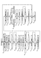
図21の(a)から(f)に示す従来装置によれば、冊子701の折り頂部を先頭にして搬送手段706,707で搬送し、位置決め手段705で冊子701の折り頂部を突き当て位置決めする(図21(b))。その後、図21(c)に示すように、把持手段702,703で冊子701の折り頂部の隣接部を挟みこんで固定し、位置決め手段705を退避させる。そして、把持手段702,703から突出して湾曲している冊子701の折り頂部を圧接ローラ704によって圧力をかけながら走行させる。こうして湾曲していた冊子701の折り頂部が角付けされる。   According to the conventional apparatus shown in FIGS. 21A to 21F, the booklet 701 is conveyed by the conveying means 706 and 707 with the folding top of the booklet 701 at the head, and the positioning means 705 abuts and positions the folding top of the booklet 701. (FIG. 21 (b)). Thereafter, as shown in FIG. 21 (c), the gripping means 702 and 703 sandwich and fix the adjacent portion of the folding top of the booklet 701, and the positioning means 705 is retracted. Then, the folded top portion of the booklet 701 protruding from the gripping means 702 and 703 is caused to run while being pressed by the pressure roller 704. In this way, the folded top portion of the booklet 701 that is curved is rounded.

図21(a)は圧接ローラ704の走行方向を示す模式図である。圧接ローラ704は把持手段702,703によって冊子701を挟み込むまでは、冊子701とは接触しない領域に退避している。そして冊子701を挟んで固定すると、圧接ローラ704は冊子701の一端から他端へ折り頂部に圧をかけながら移動する。   FIG. 21A is a schematic diagram showing the traveling direction of the pressure roller 704. The pressure roller 704 is retracted to an area where it does not come into contact with the booklet 701 until the booklet 701 is sandwiched between the gripping means 702 and 703. When the booklet 701 is sandwiched and fixed, the pressure roller 704 moves while applying pressure to the top of the booklet 701 from one end to the other end.

図21(e)は圧接されて角付けされた冊子701の折り頂部を、図21(d)は角付け(変形)処理を終えた冊子701が排出トレイ708に排出される様子を示している。   FIG. 21E shows a folded top portion of the booklet 701 that is crimped and crimped, and FIG. 21D shows a state in which the booklet 701 that has undergone the squaring (deformation) processing is discharged to the discharge tray 708. .

特開平2001−260564号公報JP-A-2001-260564

しかしながら、把持手段702,703から突出した冊子701の折り頂部を圧接するので、その突出量が大きいと変形処理された折り頂部の変形部709a,709bが図21(f)のように外側へ出っ張ってしまい、見栄えが低下することがあった。また、前記冊子701を把持手段702,703で把持したとき、把持手段702,703の角部702a,703aにより前記冊子701の折り頂部周囲に圧接痕がついてしまうという問題があった。   However, since the folded top portion of the booklet 701 protruding from the gripping means 702 and 703 is pressed, if the protruding amount is large, the deformed portions 709a and 709b of the folded top portion protrude outward as shown in FIG. 21 (f). The appearance may deteriorate. Further, when the booklet 701 is gripped by the gripping means 702 and 703, there is a problem that the corners 702a and 703a of the gripping means 702 and 703 cause pressure contact marks around the folding top of the booklet 701.

図22は角付け処理された冊子の折り頂部を示している。角付け処理された折り頂部の角709a,709bは、冊子の厚さ方向に広がり、角付け処理された面の幅は、冊子の厚さより大きくなり、前述の圧接痕もついてしまっている。さらに、本来、角付けする必要のない冊子中心のシートの折り頂部709cをも変形させてしまっている。   FIG. 22 shows the folded top portion of the booklet that has been subjected to the squaring process. The corners 709a and 709b of the folded top portions subjected to the squaring process spread in the thickness direction of the booklet, and the width of the surface subjected to the squaring process is larger than the thickness of the booklet, and the above-described pressure contact marks are caused. Furthermore, the folded top portion 709c of the sheet at the center of the booklet, which does not need to be squared, is also deformed.

本発明の目的は、冊子の折り頂部に圧接痕をつけることなく、冊子の折り頂部を見栄えよく角付け(変形)処理することである。   An object of the present invention is to perform the cornering (deformation) processing of the booklet's folded top portion without making a pressure contact mark on the folded top portion of the booklet.

上記課題を解決するため、本発明は、折り畳まれたシートからなる冊子を対向する保持部材対で挟圧して保持する保持手段と、前記保持部材対間に進入して前記保持された冊子の折り頂部に圧接して前記冊子の折り頂部を変形処理する圧接手段と、を有し、前記圧接手段は、冊子の厚さ方向の厚さが異なる複数の圧接部材を有し、前記複数の圧接部材のうち前記保持部材対間に進入可能で、前記保持部材対に挟圧保持された冊子の厚さに最も近い厚さを有する圧接部材を選択して変形処理を行うことを特徴とする。 In order to solve the above problems, the present invention provides a holding means for holding and holding a booklet made of a folded sheet by a pair of opposing holding members, and folding the booklet that is held by entering between the holding member pair. Pressure contact means for deforming the folded top portion of the booklet by pressure contact with the top portion, the pressure contact means having a plurality of pressure contact members having different thicknesses in the thickness direction of the booklet, and the plurality of pressure contact members Among them, a pressure contact member that can enter between the holding member pair and has a thickness closest to the thickness of the booklet held by the holding member pair is selected, and the deformation process is performed.

本発明によれば、冊子の厚さに応じた適正な幅の平滑面が形成されるため、冊子の折り頂部に圧接痕をつけることなく、冊子の折り頂部を見栄えよく変形処理することができる。   According to the present invention, since a smooth surface having an appropriate width according to the thickness of the booklet is formed, the folding top portion of the booklet can be deformed with good appearance without making a pressure contact mark on the folding top portion of the booklet. .

本発明の第1の実施形態に係るシート処理装置が適用可能な画像形成システムの全体構成を示す断面図1 is a cross-sectional view illustrating an overall configuration of an image forming system to which a sheet processing apparatus according to a first embodiment of the present invention is applicable. 上記シート処理装置の構成を示す断面図Sectional drawing which shows the structure of the said sheet processing apparatus 角付け処理後の冊子を示す斜視図Perspective view showing booklet after squaring process (a)は角付け処理部の構成を示す断面図、(b)は厚さ検知センサ周辺の拡大図(A) is sectional drawing which shows the structure of a squaring processing part, (b) is an enlarged view of a thickness detection sensor periphery. 角付けユニットの上面図Top view of the squaring unit 角付けユニットの正面図Front view of square unit (a)〜(f)は押さえ板の保持面間の間隔と各片の関係を示す要部拡大図 (A)-(f) is a principal part enlarged view which shows the space | interval between the holding surfaces of a pressing plate, and the relationship of each piece. (a)、(b)は角付けユニットの動作を示す上面図 (A), (b) is a top view showing the operation of the squaring unit (a)、(b)は角付けユニットの動作を示す上面図 (A), (b) is a top view showing the operation of the squaring unit (a)、(b)は角付けユニットの動作を示す上面図 (A), (b) is a top view showing the operation of the squaring unit 画像形成システムの制御系のブロック図Block diagram of control system of image forming system 角付けユニットの制御系のブロック図Block diagram of the control system of the squaring unit 角付け処理モードの動作の流れを示すフローチャートFlow chart showing the operation flow in the squaring process mode 角付け処理モード無しの動作の流れを示すフローチャートFlow chart showing the flow of operation without squaring process mode 角付け処理モード有りの動作の流れを示すフローチャートFlow chart showing the flow of operation with squaring mode 角付けユニットの動作を示す上面図Top view showing the operation of the squaring unit 角付けユニットの動作を示す上面図Top view showing the operation of the squaring unit 角付けユニットの動作を示す上面図Top view showing the operation of the squaring unit (a)〜(f)は本発明の第2の実施形態に係る押さえ板の保持面間の間隔と各片の関係を示す要部拡大図 (A)-(f) is a principal part enlarged view which shows the space | interval between the holding surfaces of the holding plate which concerns on the 2nd Embodiment of this invention, and the relationship of each piece. (a)、(b)は本発明の第3の実施形態における冊子の厚さを検知する構成例を示す要部断面図 (A), (b) is principal part sectional drawing which shows the structural example which detects the thickness of the booklet in the 3rd Embodiment of this invention. (a)〜(f)は従来技術の説明図 (A)-(f) is explanatory drawing of a prior art. 従来技術の説明図Illustration of prior art

以下、図面を参照して、本発明の好適な実施の形態を例示的に詳しく説明する。ただし、以下の実施形態に記載されている構成部品の寸法、材質、形状、それらの相対配置などは、本発明が適用される装置の構成や各種条件により適宜変更されるべきものである。従って、特に特定的な記載がない限りは、本発明の範囲をそれらのみに限定する趣旨のものではない。   Hereinafter, exemplary embodiments of the present invention will be described in detail with reference to the drawings. However, the dimensions, materials, shapes, and relative arrangements of the components described in the following embodiments should be appropriately changed according to the configuration of the apparatus to which the present invention is applied and various conditions. Therefore, unless specifically stated otherwise, the scope of the present invention is not intended to be limited thereto.

ここでは、画像形成装置本体とシート処理装置とを備えた画像形成システムを例示して説明する。また、シート処理装置は、フィニッシャ500、中綴じ製本部800、角付け処理部600等で構成されるシート処理装置を例示している。これに限らず、フィニッシャ500、中綴じ製本部800、角付け処理部600、その他の処理部を種々の組み合わせにより一体化させた構成でもよい。   Here, an image forming system including an image forming apparatus main body and a sheet processing apparatus will be described as an example. Further, the sheet processing apparatus exemplifies a sheet processing apparatus including a finisher 500, a saddle stitch bookbinding unit 800, a squaring processing unit 600, and the like. The configuration is not limited to this, and the finisher 500, the saddle stitch bookbinding unit 800, the squaring processing unit 600, and other processing units may be integrated by various combinations.

[第1実施形態]
(画像形成システムの構成)
まず図1及び図2を用いて画像形成システムの全体構成について説明する。図1は画像形成システムの主要部の構成を示す断面図である。図2はシート処理装置の要部を示す断面図である。
[First Embodiment]
(Configuration of image forming system)
First, the overall configuration of the image forming system will be described with reference to FIGS. FIG. 1 is a cross-sectional view showing a configuration of a main part of the image forming system. FIG. 2 is a cross-sectional view showing a main part of the sheet processing apparatus.

画像形成システム1000は、図1及び図2に示すように、画像形成装置本体10と、シート処理装置20を備えている。シート処理装置20は、フィニッシャ500、中綴じ製本部800、角付け処理部600から構成されている。上記中綴じ製本部800、角付け処理部600等は、オプションとして装備することができる。画像形成装置本体10は、原稿給送部100、原稿の画像を読み取るイメージリーダ200及びシートに画像を記録するプリンタ300を備えている。   As shown in FIGS. 1 and 2, the image forming system 1000 includes an image forming apparatus main body 10 and a sheet processing apparatus 20. The sheet processing apparatus 20 includes a finisher 500, a saddle stitch binding unit 800, and a squaring processing unit 600. The saddle stitch bookbinding unit 800, the squaring processing unit 600, and the like can be optionally provided. The image forming apparatus main body 10 includes a document feeder 100, an image reader 200 that reads an image of a document, and a printer 300 that records an image on a sheet.

(画像形成装置本体の構成) (Configuration of image forming apparatus main body)

原稿給送部100によって原稿が読取位置へ搬送され、イメージリーダ200により読取位置で読み取られた原稿の画像データは、所定の画像処理が施されて露光制御部110へ送られる。露光制御部110は、画像信号に応じたレーザ光を出力する。レーザ光は、ポリゴンミラー110aにより走査されながら感光体ドラム111上に照射される。画像形成部1003を構成する感光体ドラム111上には走査されたレーザ光に応じた静電潜像が形成される。感光体ドラム111上に形成された静電潜像は、現像器113により現像され、トナー像として可視化される。   The original is conveyed to the reading position by the original feeding unit 100, and the image data of the original read at the reading position by the image reader 200 is subjected to predetermined image processing and sent to the exposure control unit 110. The exposure control unit 110 outputs laser light corresponding to the image signal. The laser light is irradiated onto the photosensitive drum 111 while being scanned by the polygon mirror 110a. An electrostatic latent image corresponding to the scanned laser beam is formed on the photosensitive drum 111 constituting the image forming unit 1003. The electrostatic latent image formed on the photosensitive drum 111 is developed by the developing unit 113 and visualized as a toner image.

一方、シートは、給送部1002を構成するカセット114,115、手差し給送部125、両面搬送パス124の何れかから転写部116へ搬送される。そして、可視化されたトナー像が転写部116においてシートに転写される。転写後のシートは、定着部117にて定着処理が施される。   On the other hand, the sheet is conveyed to the transfer unit 116 from any of the cassettes 114 and 115, the manual feeding unit 125, and the double-sided conveyance path 124 that constitute the feeding unit 1002. The visualized toner image is transferred to the sheet in the transfer unit 116. The sheet after the transfer is subjected to a fixing process in the fixing unit 117.

そして、定着部117を通過したシートを、切替部材121により一旦パス122に導き、シートの後端が切替部材121を抜けた後にスイッチバックさせ、切替部材121により排出ローラ118へ導く。そして、排出ローラ118によりシートをプリンタ300から排出する。これによりトナー像が形成された面を下向きの状態(フェイスダウン状態)でプリンタ300から排出できる。これを反転排出と称する。   The sheet that has passed through the fixing unit 117 is once guided to the path 122 by the switching member 121, switched back after the trailing edge of the sheet has passed through the switching member 121, and guided to the discharge roller 118 by the switching member 121. Then, the sheet is discharged from the printer 300 by the discharge roller 118. As a result, the surface on which the toner image is formed can be discharged from the printer 300 in a downward state (face-down state). This is called reverse discharge.

上述したようにフェイスダウン状態でシートを機外に排出することにより、先頭ページから順に画像形成処理を行う。この場合、例えば、原稿給送部100を使用して画像形成処理を行う場合や、コンピュータからの画像データに対する画像形成処理を行う場合にページ順序を揃えることができる。   As described above, the sheets are discharged out of the apparatus in the face-down state, thereby performing image forming processing in order from the first page. In this case, for example, the page order can be aligned when the image forming process is performed using the document feeder 100 or when the image forming process is performed on the image data from the computer.

また、シートの両面に画像形成処理を行う場合は、シートを定着部117からまっすぐ排出ローラ118方向へと導き、シートの後端が切替部材121を抜けた直後にシートをスイッチバックし、切替部材121により両面搬送パス124へと導く。そして、両面搬送パス124へ導かれたシートは、前述したように感光体ドラム111と転写部116との間に再度給送される。   When image forming processing is performed on both sides of the sheet, the sheet is guided straight from the fixing unit 117 toward the discharge roller 118, and the sheet is switched back immediately after the trailing edge of the sheet passes through the switching member 121. 121 guides to the duplex conveyance path 124. The sheet guided to the duplex conveyance path 124 is fed again between the photosensitive drum 111 and the transfer unit 116 as described above.

(シート処理装置の構成)
画像形成装置本体10のプリンタ300から排出されたシートは、シート処理装置(シート処理部)20を構成するフィニッシャ500に送られる。
(Configuration of sheet processing apparatus)
The sheet discharged from the printer 300 of the image forming apparatus main body 10 is sent to a finisher 500 constituting the sheet processing apparatus (sheet processing unit) 20.

次に、フィニッシャ500の構成について、図1、図2を参照しながら説明する。   Next, the configuration of the finisher 500 will be described with reference to FIGS.

(フィニッシャ)
フィニッシャ500は、排出ローラ118によりプリンタ300から搬送されたシートを取り込み、そのシートの処理を選択的に行うようになっている。シートの処理には、取り込んだ複数のシートを整合して、1つのシート束として束ねる処理、シート束の後端側をステイプルするステイプル処理(綴じ処理)、ソート処理、ノンソート処理等があり、これらのシートの処理が選択的に行われる。
(Finisher)
The finisher 500 takes in the sheet conveyed from the printer 300 by the discharge roller 118 and selectively processes the sheet. Sheet processing includes processing for aligning a plurality of captured sheets and bundling them as one sheet bundle, stapling processing for binding the trailing end of the sheet bundle (binding processing), sorting processing, non-sorting processing, etc. These sheets are selectively processed.

図2に示すように、フィニッシャ500は、搬送されたシートを装置内部に取り込むための搬送パス520を有し、中綴じ製本部800へシートを供給する下排出パス522へシートを搬送する。この搬送パス520には、必要に応じて搬送されるシートの後端部に穴あけ(穿孔)処理を行うパンチユニット530と、複数の搬送ローラ対が設けられている。   As shown in FIG. 2, the finisher 500 has a conveyance path 520 for taking the conveyed sheet into the apparatus, and conveys the sheet to a lower discharge path 522 that supplies the sheet to the saddle stitch binding unit 800. The conveyance path 520 is provided with a punch unit 530 that performs a punching (punching) process at the rear end portion of the sheet conveyed as necessary, and a plurality of conveyance roller pairs.

前記下排出パス522の途中には切替部材514が設けられている。切替部材514の切り替えによりサドル排出パス523に案内されたシートは、中綴じ製本部800へ送られる。   A switching member 514 is provided in the middle of the lower discharge path 522. The sheet guided to the saddle discharge path 523 by switching the switching member 514 is sent to the saddle stitch bookbinding unit 800.

(中綴じ製本部)
次に、中綴じ製本部800の構成を説明する。
(Saddle stitch bookbinding)
Next, the configuration of the saddle stitch bookbinding unit 800 will be described.

中綴じ製本部800に送られたシートは、サドル入口ローラ対801に受け渡され、サイズに応じてソレノイドにより動作する切替部材802により搬入口を選択されて、中綴じ製本部800の収納ガイド803内に搬入される。搬入されたシートは、滑りローラ804により先端が可動式のシート位置決め部材805に接するまで搬送される。サドル入口ローラ対801と滑りローラ804はモータM1により駆動される。また、収納ガイド803の途中位置には、収納ガイド803を挟んで対向配置されたステイプラ820が設けられている。ステイプラ820は、針を突き出すドライバー820aと突き出された針を折り曲げるアンビル820bとに分割されている。なお、前記シート位置決め部材805は、シート搬入時において、シート搬送方向中央部が、このステイプラ820の綴じ位置になる位置で停止する。シート位置決め部材805は、モータM2の駆動を受けて移動可能であり、シートサイズに応じて位置を変える。   The sheet sent to the saddle stitch bookbinding unit 800 is delivered to the saddle entrance roller pair 801, and the carry-in port is selected by the switching member 802 operated by a solenoid according to the size, and the storage guide 803 of the saddle stitch bookbinding unit 800 is selected. It is carried in. The loaded sheet is conveyed by the sliding roller 804 until the leading end contacts the movable sheet positioning member 805. The saddle entrance roller pair 801 and the sliding roller 804 are driven by a motor M1. In addition, a stapler 820 is provided in the middle of the storage guide 803 so as to face the storage guide 803. The stapler 820 is divided into a driver 820a that projects a needle and an anvil 820b that bends the projected needle. The sheet positioning member 805 stops at a position where the central portion in the sheet conveying direction is the binding position of the stapler 820 when the sheet is carried in. The sheet positioning member 805 is movable by being driven by the motor M2, and changes its position according to the sheet size.

ステイプラ820の下流側には、折りローラ対810a,810bが設けられている。折りローラ対810a,810bの対向位置には、収納ガイド803を介して、突き出し部材830が設けられている。この突き出し部材830は、収納ガイド803から退避した位置をホームポジションとし、モータM3の駆動により収納された複数枚のシートからなるシート束に向けて突き出す。これにより、シート束を、折りローラ対810a,810bのニップに押し込みながら折り畳む。突き出し部材830はその後、再びホームポジションに戻る。なお、折りローラ対810a,810b間には、シート束に折り目を付けるのに充分な圧がバネ(不図示)により掛けられている。折り目が付けられたシート束は、第1折り搬送ローラ対811a,811b、第2折り搬送ローラ対812a,812bを介して、角付け処理部600に向けて排出される。第1折り搬送ローラ対811a,811b、及び第2折り搬送ローラ対812a,812bにも、折り目が付けられたシート束を搬送、停止させるのに充分な圧がそれぞれ掛けられている。なお、折りローラ対810a,810b、第1折り搬送ローラ対811a,811b、第2折り搬送ローラ対812a,812bは、同一のモータM4により等速回転する。   On the downstream side of the stapler 820, folding roller pairs 810a and 810b are provided. A protruding member 830 is provided at a position facing the pair of folding rollers 810a and 810b via a storage guide 803. The protruding member 830 protrudes toward a sheet bundle composed of a plurality of sheets stored by driving the motor M3 with the position retracted from the storage guide 803 as a home position. Thus, the sheet bundle is folded while being pushed into the nip of the pair of folding rollers 810a and 810b. Thereafter, the protruding member 830 returns to the home position again. Note that a sufficient pressure is applied between the pair of folding rollers 810a and 810b by a spring (not shown) to crease the sheet bundle. The folded sheet bundle is discharged toward the squaring processing unit 600 via the first fold conveyance roller pair 811a and 811b and the second fold conveyance roller pair 812a and 812b. The first fold conveyance roller pair 811a and 811b and the second fold conveyance roller pair 812a and 812b are also applied with sufficient pressure to convey and stop the folded sheet bundle. The pair of folding rollers 810a and 810b, the first pair of folding and conveying rollers 811a and 811b, and the pair of second folding and conveying rollers 812a and 812b are rotated at the same speed by the same motor M4.

また、綴じ処理を行わずにシート束を折り畳む場合は、収納ガイド803に収納されたシート束の搬送方向中央部が折りローラ対810a,810bのニップ位置にくるように、シート束を移動させる。一方、ステイプラ820で綴じられたシート束を折り畳む場合は、ステイプル処理終了後に、シート束のステイプル位置(搬送方向中央部)が折りローラ対810a,810bのニップ位置にくるように、ステイプル位置にあるシート束を移動させる。これによりステイプル処理を施した位置を中心にしてシート束を折り畳むことができる。   When the sheet bundle is folded without performing the binding process, the sheet bundle is moved so that the central portion in the conveyance direction of the sheet bundle stored in the storage guide 803 is positioned at the nip position between the pair of folding rollers 810a and 810b. On the other hand, when the sheet bundle bound by the stapler 820 is folded, the staple position is in the staple position so that the staple position (central portion in the conveyance direction) of the sheet bundle is at the nip position between the pair of folding rollers 810a and 810b. Move the sheet bundle. Accordingly, the sheet bundle can be folded around the position where the stapling process is performed.

また、折りローラ対810a,810bの位置には、折りローラ対810a,810bの外周面を周りながら収納ガイド803に突出した面を持つ整合板対815が設けられている。整合板対815は、モータM5の駆動を受けて、シートの搬送方向と直交する幅方向に移動することで、収納ガイド803に収納されたシートの幅方向の整合(位置決め)を行う。   Further, at the positions of the folding roller pairs 810a and 810b, an alignment plate pair 815 having a surface protruding to the storage guide 803 while surrounding the outer peripheral surfaces of the folding roller pairs 810a and 810b is provided. The alignment plate pair 815 receives the drive of the motor M5 and moves in the width direction orthogonal to the sheet conveyance direction to align (position) the sheets stored in the storage guide 803 in the width direction.

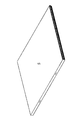
このような構成の中綴じ製本部800により、2つ折りされたシート束(折りシート束;以下、冊子という)Sが形成される。なお、冊子はこれに限定されず、綴じ処理を行わずに2つ折りしたものも含む。   The saddle stitch bookbinding portion 800 having such a configuration forms a folded sheet bundle (folded sheet bundle; hereinafter referred to as a booklet) S. Note that the booklet is not limited to this, and includes a booklet that is folded in two without performing the binding process.

(角付け処理部)
次に、図4を用いて、角付け処理部600について説明する。図4は図2の角付け処理部600の拡大図である。角付け処理部600は、中綴じ製本部800の下流に位置する。
(Squaring processing part)
Next, the squaring processing unit 600 will be described with reference to FIG. FIG. 4 is an enlarged view of the squaring processing unit 600 of FIG. The squaring processing unit 600 is located downstream of the saddle stitch bookbinding unit 800.

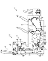
図4に示すように、角付け処理部600において、受け取り部610は、中綴じ製本部800から冊子を受け取り、搬送するための、下側のみ搬送方向に伸びる下搬送ベルト611を持つ。冊子の受け渡し時、下搬送ベルト611は搬送方向に回転をしているので、第2折り搬送ローラ対812a,812bから冊子が落下しても、その冊子が回転することなく、搬送されてきた姿勢のまま受け取ることができる。   As shown in FIG. 4, in the squaring processing unit 600, the receiving unit 610 has a lower conveying belt 611 extending in the conveying direction only on the lower side for receiving and conveying a booklet from the saddle stitch bookbinding unit 800. Since the lower conveyance belt 611 rotates in the conveyance direction when the booklet is delivered, even if the booklet falls from the second folding conveyance roller pair 812a, 812b, the booklet is conveyed without rotating. You can receive it as it is.

下搬送ベルト611を挟み、その外側にはサイドガイド対612が配設され、これらが冊子の幅方向(搬送方向と直交する方向)に動作することで、冊子の幅方向位置を修正することができる。また、サイドガイド対612の上側は、冊子の開きを防止する押さえガイド614が形成されており、下流部へスムーズに冊子を受け渡すためのガイドとして機能する。さらに下搬送ベルト611を挟んだ両側には、下搬送ベルト611と平行に移動する搬送爪613が配設されている。搬送爪613は、下搬送ベルト611と略同じ速度で正逆移動をする。下搬送ベルト611と冊子との間にすべりが生じた場合は、この搬送爪613が冊子後端と接触し、確実に冊子後端を下流側へと押し込む。なお、前記下搬送ベルト611、サイドガイド対612、搬送爪613は、それぞれモータSM1,SM2,SM3の駆動を受けて動作する。   A pair of side guides 612 is disposed on the outer side of the lower conveyance belt 611, and the position of the booklet in the width direction can be corrected by operating in the width direction of the booklet (direction perpendicular to the conveyance direction). it can. Further, a holding guide 614 for preventing the booklet from opening is formed on the upper side of the pair of side guides 612, and functions as a guide for smoothly delivering the booklet to the downstream portion. Further, conveyance claws 613 that move in parallel with the lower conveyance belt 611 are disposed on both sides of the lower conveyance belt 611. The conveyance claw 613 moves forward and backward at substantially the same speed as the lower conveyance belt 611. When a slip occurs between the lower conveyance belt 611 and the booklet, the conveyance claws 613 come into contact with the booklet rear end and reliably push the booklet rear end downstream. The lower transport belt 611, the side guide pair 612, and the transport claws 613 operate by being driven by motors SM1, SM2, and SM3, respectively.

角付け処理部600において、搬送部620は、受け取り部610から冊子を受け取り、下流へ搬送するための下搬送ベルト621、上搬送ベルト622で構成される。上搬送ベルト622は支点623を中心に冊子の厚さによって回動できるようになっており、下搬送ベルト621へバネ(不図示)により押圧されている。上下搬送ベルト621,622はモータSM4によって駆動する。入口検知センサ615は、中綴じ製本部800から冊子を受け取り、下搬送ベルト611上に冊子があることを検知する。出口検知センサ616は、冊子を検知することによりサイドガイド対612、搬送爪613を動作させるための入力信号となる。   In the squaring processing unit 600, the transport unit 620 includes a lower transport belt 621 and an upper transport belt 622 for receiving a booklet from the receiving unit 610 and transporting the booklet downstream. The upper conveyor belt 622 can be rotated around the fulcrum 623 depending on the thickness of the booklet, and is pressed against the lower conveyor belt 621 by a spring (not shown). The vertical conveyor belts 621 and 622 are driven by a motor SM4. The entrance detection sensor 615 receives a booklet from the saddle stitch bookbinding unit 800 and detects that the booklet is on the lower conveyance belt 611. The exit detection sensor 616 serves as an input signal for operating the side guide pair 612 and the conveyance claw 613 by detecting the booklet.

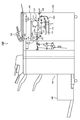
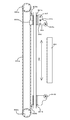
角付け処理部600において、変形処理ユニット625は、冊子の折り頂部近傍を上下から挟んで保持する押さえユニット630と、冊子の折り頂部を位置決めし、かつ折り頂部を圧接して角付けする角付けユニット640とで構成されている。   In the squaring processing unit 600, the deformation processing unit 625 includes a pressing unit 630 that holds the vicinity of the folding top portion of the booklet from above and below, and a cornering that positions the folding top portion of the booklet and presses the folding top portion to make a corner. It is comprised with the unit 640.

保持手段としての押さえユニット630は、上下動を行う上部ユニットと、上部ユニットと対向してフレームに固定される下押さえ板631に分けられている。上部ユニットは、モータSM5の駆動を受け、リンク636,637,638を介して上下動を行う強固な押さえベース632と、スライド連結部材634で連結された上押さえ板633を有し、スライド連結部材634の外周には圧縮バネ635が配置されている。保持部材対としての押さえ板631,633は、折り畳まれたシートからなる冊子を互いに平行な、対向する保持面で挟圧して保持する保持手段を構成している。押さえベース632が上位置にあるとき、上下の押さえ板631,633は離間しており、その間に冊子が搬送される。また押さえベース632が下位置にあるときには、冊子の厚さに応じて伸縮する圧縮バネ635によって、冊子は上下押さえ板631,633でしっかりと挟圧、保持される。上下押さえ板631,633の冊子との接触面(保持面)は突起のない平滑面であるので、冊子を挟圧、保持したときに冊子に圧接痕をつけるようなことがない。上死点検知センサ639は、押さえベース632が上位置にあることを検知する。厚さ検知センサ(厚さ検知手段)681は、冊子を固定(挟圧保持)したときの上押さえ板633の位置を検知することで保持面間隔を算出し、保持された冊子の厚さを求める。   The holding unit 630 as a holding means is divided into an upper unit that moves up and down and a lower holding plate 631 that is fixed to the frame so as to face the upper unit. The upper unit is driven by the motor SM5, and has a strong press base 632 that moves up and down via links 636, 637, and 638, and an upper press plate 633 that is connected by a slide connection member 634, and the slide connection member. A compression spring 635 is disposed on the outer periphery of 634. The holding plates 631 and 633 as the holding member pair constitute holding means for holding the booklet made of the folded sheets by pressing them with parallel holding faces facing each other. When the pressing base 632 is in the upper position, the upper and lower pressing plates 631 and 633 are separated from each other, and the booklet is conveyed therebetween. When the presser base 632 is in the lower position, the booklet is firmly clamped and held by the upper and lower presser plates 631 and 633 by the compression spring 635 that expands and contracts according to the thickness of the booklet. Since the contact surfaces (holding surfaces) of the upper and lower pressing plates 631 and 633 with the booklet are smooth surfaces without protrusions, there is no possibility that pressure marks are formed on the booklet when the booklet is sandwiched and held. The top dead center detection sensor 639 detects that the presser base 632 is in the upper position. The thickness detection sensor (thickness detection means) 681 calculates the holding surface interval by detecting the position of the upper pressing plate 633 when the booklet is fixed (holding pressure holding), and the thickness of the held booklet is calculated. Ask.

厚さ検知センサ681は、図4(b)に示すように、発光部681aから照射した光の反射光量(破線)を電流値に換算し、対象物との距離を測定する測距センサであり、上押さえ板633に固定されている。測定する対象物は、下押さえ板631であり、上下の押さえ板631,633の間隔が広くなるほど、つまり冊子厚が厚いほど、電流値は下がる。このようにして上下の押さえ板631,633で把持される冊子の厚さを測定することができる。図中Sは、上下の押さえ板631、633で保持された冊子である。 As shown in FIG. 4B, the thickness detection sensor 681 is a distance measuring sensor that converts the amount of reflected light (broken line) of the light emitted from the light emitting unit 681a into a current value and measures the distance to the object. The upper pressing plate 633 is fixed. The object to be measured is the lower pressing plate 631 , and the current value decreases as the distance between the upper and lower pressing plates 631 and 633 increases, that is, as the booklet thickness increases. In this way, the thickness of the booklet held by the upper and lower pressing plates 631 and 633 can be measured. In the figure, S is a booklet held by upper and lower pressing plates 631 and 633.

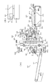
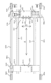
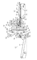
次に、図4に併せ、図5、図6を用いて角付けユニット640を説明する。図5は図4の図中X−Xの矢視図であり、図6は図4の角付けユニット640を右側面から見た図である。   Next, the squaring unit 640 will be described with reference to FIGS. FIG. 5 is a view taken along the line XX in FIG. 4, and FIG. 6 is a view of the squaring unit 640 of FIG. 4 as viewed from the right side.

角付けユニット640には、移動ユニット656aがあり、枠体(不図示)に支持されたスライド軸642,643に沿って図5、図6の図中矢印A方向に移動可能に支持されている。移動ユニット656aは、連結部材653aによってタイミングベルト652aに取り付けられ、プーリ654a,655aを介してモータSM6によって駆動される。移動ユニット656aは、移動ベース641aを有し、移動ベース641aに固定されたスライド軸646,647に切替ユニット657をスライド可能に支持している。切替ユニット657はスライドネジ645、モータSM8によりスライド軸646,647に沿って図6の図中矢印B方向に移動することができる。切替ユニット657には、支持軸648aが切替ベース644に回転自在に取り付けられている。支持軸648aには、ストッパー片649a、第1圧接片650、第2圧接片651が固定されている。ストッパー片649aは後述するストッパー片649bと協同し、搬送されてくる冊子の折り頂部が突き当たることで、冊子を角付け処理する所定の位置に位置決めする位置決め手段である。圧接手段を構成する第1圧接片650、第2圧接片651は、冊子の折り頂部を圧接して冊子の折り頂部を角付け処理する圧接部材である。第1圧接片650、第2圧接片651は、冊子の厚さに応じて切替ユニット657が図6の図中矢印B方向に移動することで切り替えられる。切替ユニット657には基準位置検知センサ659があり、図中矢印B方向に移動するときの基準位置となっている。   The squaring unit 640 includes a moving unit 656a and is supported so as to be movable in the direction of arrow A in FIGS. 5 and 6 along slide shafts 642 and 643 supported by a frame (not shown). . The moving unit 656a is attached to the timing belt 652a by a connecting member 653a, and is driven by the motor SM6 via pulleys 654a and 655a. The moving unit 656a has a moving base 641a, and a switching unit 657 is slidably supported on slide shafts 646 and 647 fixed to the moving base 641a. The switching unit 657 can be moved in the direction of arrow B in FIG. 6 along the slide shafts 646 and 647 by the slide screw 645 and the motor SM8. A support shaft 648 a is rotatably attached to the switching base 644 in the switching unit 657. A stopper piece 649a, a first pressure contact piece 650, and a second pressure contact piece 651 are fixed to the support shaft 648a. The stopper piece 649a is a positioning unit that cooperates with a stopper piece 649b, which will be described later, and positions the booklet at a predetermined position where the booklet is squared when the folded top portion of the booklet abuts. The first press contact piece 650 and the second press contact piece 651 constituting the press contact means are press contact members that press-contact the folded top portion of the booklet and squab the folded top portion of the booklet. The first pressure contact piece 650 and the second pressure contact piece 651 are switched by the switching unit 657 moving in the direction of arrow B in FIG. 6 according to the thickness of the booklet. The switching unit 657 has a reference position detection sensor 659, which is a reference position when moving in the direction of arrow B in the figure.

また、角付けユニット640には、移動ユニット656bもあり、枠体(不図示)に支持されたスライド軸642,643に沿って図5、図6の図中矢印A方向に移動可能に支持されている。移動ユニット656bは、連結部材653bによってタイミングベルト652bに取り付けられ、プーリ654b,655bを介してモータSM7によって駆動される。移動ユニット656bは、移動ベース641bを有し、移動ベース641bには支持軸648bが回転自在に取り付けられており、支持軸648bにはストッパー片649bが固定されている。ストッパー片649bはストッパー片649aと協同し、搬送されてくる冊子の折り頂部が突き当たることで、冊子を角付け処理する所定の位置に位置決めする位置決め手段である。ストッパー片649a,649bは搬送されてきた冊子Sのシート搬送方向における位置決めするとともに、冊子Sの傾きを補正するために互いにシート幅方向に所定間隔離れた位置で冊子Sを受け止めるよう設けられる。ストッパー片649a、649bによって位置決めされる冊子の折り頂部の位置は、保持手段を構成する保持部材対としての上下の押さえ板631、633の端部から所定量、内側(保持部材対間)に入り込んだ位置である。   The squaring unit 640 also includes a moving unit 656b, which is supported so as to be movable in the direction of arrow A in FIGS. 5 and 6 along slide shafts 642 and 643 supported by a frame (not shown). ing. The moving unit 656b is attached to the timing belt 652b by a connecting member 653b, and is driven by a motor SM7 via pulleys 654b and 655b. The moving unit 656b has a moving base 641b. A support shaft 648b is rotatably attached to the moving base 641b, and a stopper piece 649b is fixed to the support shaft 648b. The stopper piece 649b cooperates with the stopper piece 649a, and is a positioning means for positioning the booklet at a predetermined position where the booklet is squashed by abutting the folded top portion of the booklet being conveyed. The stopper pieces 649a and 649b are positioned so as to receive the booklet S at positions spaced apart from each other by a predetermined distance in the sheet width direction in order to correct the inclination of the booklet S while positioning the booklet S being conveyed in the sheet conveyance direction. The position of the folding top portion of the booklet positioned by the stopper pieces 649a and 649b enters inside (between the holding member pair) by a predetermined amount from the end portions of the upper and lower pressing plates 631 and 633 as a holding member pair constituting the holding means. Is the position.

移動ユニット656a、移動ユニット656bには、それぞれ、基準位置検知センサ658a,658bがあり、角付けユニット640が図中矢印A方向に移動するときの基準位置となっている。なお、矢印A方向は、冊子の搬送方向と直交する方向であり、冊子の折り頂部に沿う方向である。   The moving unit 656a and the moving unit 656b have reference position detection sensors 658a and 658b, respectively, which serve as reference positions when the squaring unit 640 moves in the direction of arrow A in the figure. The arrow A direction is a direction orthogonal to the booklet transport direction, and is a direction along the folded top of the booklet.

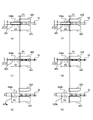
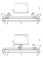
ストッパー片649a,649b、第1圧接片650、第2圧接片651はいずれも円盤状に設けられた部材であり、図7に示すような大きさの関係になっている。図7(a)、(b)のように、ストッパー片649a,649bの直径はD1である。ストッパー片649a,649bは、上下押さえ板631,633の保持面間に進入し、冊子S1を上下押さえ板631,633の搬送方向下流端部から突出しない所定の位置に位置決めするようになっている。ストッパー片649a,649bの厚さはH1であり、搬送されてくる冊子の厚さより厚くなっていて、厚い冊子でもその折り頂部がストッパー片を乗り越えずに位置決めできるようになっている。 The stopper pieces 649a, 649b, the first pressure contact piece 650, and the second pressure contact piece 651 are all members provided in a disk shape, and have a size relationship as shown in FIG. As shown in FIGS. 7A and 7B, the stopper pieces 649a and 649b have a diameter D1. The stopper pieces 649a and 649b enter between the holding surfaces of the upper and lower pressing plates 631 and 633 to position the booklet S1 at a predetermined position that does not protrude from the downstream end of the upper and lower pressing plates 631 and 633 in the conveying direction. . The thickness of the stopper pieces 649a and 649b is H1, which is thicker than the thickness of the conveyed booklet, so that the top of the folded booklet can be positioned without getting over the stopper piece.

なお、第2圧接片651に比べて薄い冊子に対応する第1圧接片650は、ストッパー片649aに隣接している。これは、冊子作成時の生産性が高い、薄い冊子に対する処理能力を高めるための配慮である。これにより、ストッパー片649aから第1圧接片650への切り替え、またはその逆の切り替え時間を短縮している。   The first press contact piece 650 corresponding to a booklet thinner than the second press contact piece 651 is adjacent to the stopper piece 649a. This is a consideration for increasing the processing capacity for thin booklets with high productivity at the time of booklet creation. This shortens the switching time from the stopper piece 649a to the first pressure contact piece 650, or vice versa.

ここでは、中綴じ製本部800で作成される冊子として、シート1枚を二つ折りした冊子からシート25枚を二つ折りした冊子を例示している。そのうち、1枚から10枚までのシートを二つ折りした冊子は角付け処理せず、11枚から25枚までのシートを二つ折りした冊子を角付け処理するように設定している。これは、1枚から10枚までのシートを二つ折りした冊子は冊子厚さが薄く、折り頂部の湾曲部が小さいため、角付け処理する変形領域(圧接量)を確保しにくい、十分な折りであるため角付け処理しても冊子の開き易さが変わらないことによる。シート11枚から25枚を二つ折りした冊子は角付け処理する。シート11枚から25枚を二つ折りした際に、冊子の厚さに幅があるため、冊子の厚さを複数段階(ここでは二段階)に分けて、角付け処理を行う。また、冊子厚さがT2からT3のときは図7(c)、(d)のように冊子S2の厚さより薄い厚さH2の第1圧接片650を選択し、冊子S2の折り頂部の角付け処理を行う。一方、冊子厚さがT4からT5のときは図7(e)、(f)のように冊子S3の厚さより薄い厚さH3の第2圧接片651を選択し、冊子S3の折り頂部の角付け処理を行う。すなわち、保持された冊子の厚さに応じて、上下押さえ板の保持面間の間隔(冊子の厚さ)より厚さ薄い圧接片のうち、前記保持面間の間隔に最も近い厚さを有する圧接片を選択して角付け処理を行うようになっている。このように、複数の圧接片のうち、上下押さえ板631,633の間に進入可能で、挟圧保持された冊子の厚さに最も近い厚さを有する圧接片を選択して角付け処理を行うことにより、冊子の厚さに応じた適正な幅の平滑面が形成される。これにより、冊子の折り頂部に圧接痕をつけることなく、冊子の折り頂部を見栄えよく変形処理することができる。 Here, as a booklet created by the saddle stitch bookbinding unit 800, a booklet in which 25 sheets are folded in half from a booklet in which one sheet is folded in two is illustrated. Among them, the booklet obtained by folding one to ten sheets in half is not subjected to the squaring process, and the booklet obtained by folding eleven to 25 sheets in half is set to the squaring process. This is because a booklet in which 1 to 10 sheets are folded in half has a small booklet thickness and a small bending portion at the top of the fold, so that it is difficult to secure a deformation area (pressure contact amount) for squaring. Therefore, the ease of opening the booklet does not change even when the squaring process is performed. A booklet in which 11 to 25 sheets are folded in half is subjected to a squaring process. When the 11 sheets to 25 sheets are folded in half, the thickness of the booklet is wide, so the booklet thickness is divided into a plurality of stages (here, two stages), and the squaring process is performed. When the booklet thickness is from T2 to T3, the first press-contacting piece 650 having a thickness H2 thinner than the thickness of the booklet S2 is selected as shown in FIGS. 7C and 7D, and the corner of the folded top portion of the booklet S2 is selected. Perform the attachment process. On the other hand, when the booklet thickness is from T4 to T5, the second pressure contact piece 651 having a thickness H3 thinner than the thickness of the booklet S3 is selected as shown in FIGS. 7E and 7F, and the corner of the folded top portion of the booklet S3 is selected. Perform the attachment process. That is, depending on the thickness of the retained booklet, among the upper and lower pressing plate spacing (thickness of the booklet) from the small thickness pressing member between the holding surface of the closest thickness to the spacing between the holding surface The press contact piece is selected and the squaring process is performed. As described above, among the plurality of press contact pieces, the press contact piece that can enter between the upper and lower pressing plates 631 and 633 and has the thickness closest to the thickness of the booklet held by pressing is selected, and the squaring process is performed. By doing so, a smooth surface having an appropriate width according to the thickness of the booklet is formed. Accordingly, the folding top portion of the booklet can be pleasingly deformed without making a pressure contact mark on the folding top portion of the booklet.

また、ストッパー片649a,649bの直径D1、第1圧接片650の直径D2、第2圧接片651の直径D3は、D1<D2<D3という関係になっている。更に、比較的薄めの冊子を角付け処理するのに使用する第1圧接片650のときは変形領域(圧接量)P2=(D2−D1)/2である。一方、薄めの冊子に比べて厚い冊子を角付け処理するのに使用する第2圧接片651のときは変形領域(圧接量)P3=(D3−D1)/2である。すなわち、薄めの冊子に比べて厚い冊子の変形領域(圧接量)が大きくなるよう(P2<P3)に設定している。本実施の形態において、角付け処理する変形領域(圧接量)はストッパー片による位置決め位置ではなく、圧接片の直径の大きさで設定している。   Further, the diameter D1 of the stopper pieces 649a and 649b, the diameter D2 of the first pressure contact piece 650, and the diameter D3 of the second pressure contact piece 651 have a relationship of D1 <D2 <D3. Furthermore, in the case of the first pressure contact piece 650 used for squaring a relatively thin booklet, the deformation area (pressure contact amount) P2 = (D2-D1) / 2. On the other hand, the deformation area (pressure contact amount) P3 = (D3−D1) / 2 in the case of the second pressure contact piece 651 used for squaring a thick booklet as compared with a thin booklet. That is, the deformation area (pressure contact amount) of the thick booklet is set to be larger than that of the thin booklet (P2 <P3). In the present embodiment, the deformation area (pressure contact amount) to be squared is set not by the positioning position by the stopper piece but by the size of the diameter of the pressure contact piece.

なお、この圧接片の直径の大きさ、変形領域(圧接量)は、上下押さえ板631,633の保持面間への圧接片の進入量に相当するものである。上述のように、薄い冊子でも厚い冊子でも同じストッパー片649a,649bで位置決めするので、冊子の厚さにかかわらず冊子を同じ位置に位置決めすることができる。そして、冊子の厚さが薄いと角付け処理に使用する圧接片の厚さ薄くて直径が小さく、冊子の厚さが厚いと角付け処理に使用する圧接片の厚さ厚くて直径が大きくなっている。これは、冊子の厚さによらず位置決めする位置を同じにして、薄い冊子に比べて厚い冊子の圧接量が常に大きくなるように設定し、薄い冊子の過度の変形や厚い冊子の変形不足を回避し、角付け処理された冊子の形状を安定化するためである。 The size of the pressure contact piece and the deformation area (pressure contact amount) correspond to the amount of the pressure contact piece entering between the holding surfaces of the upper and lower pressing plates 631 and 633. As described above, the thin booklet and the thick booklet are positioned by the same stopper pieces 649a and 649b, so that the booklet can be positioned at the same position regardless of the thickness of the booklet. The thin thickness of the pressing member to be used with thin thickness of the booklet to the squaring process small diameter and thicker the thickness of the pressing member to be used with a thick thickness of the booklet to the squaring process diameter It is getting bigger. This is because the positioning position is the same regardless of the thickness of the booklet, and the amount of press contact of the thick booklet is always larger than that of the thin booklet, and excessive deformation of the thin booklet or insufficient deformation of the thick booklet is avoided. This is for avoiding and stabilizing the shape of the booklet subjected to the squaring process.

ここでは、冊子の厚さを2つの範囲に場合わけし、2種類の厚さと直径の違う圧接片を使用した例を述べたが、これに限定されるものではない。例えば、冊子の厚さの場合分けを3つ4つとさらに細かくして使用する圧接片の種類を増やしてもよい。 In this example, the thickness of the booklet is divided into two ranges, and an example in which two types of thickness and different pressure contact pieces with different diameters are used has been described. However, the present invention is not limited to this. For example, in the case of the thickness of the booklet, the number of types of pressure contact pieces to be used may be increased by further dividing the division into three and four.

本実施の形態において、変形領域P2、P3における上下押さえ板631、633の保持面は、冊子の折り頂部が圧接される前には冊子の折り頂部と当接しない。そして、圧接片による冊子の折り頂部の圧接が開始されると、上下押さえ板631、633の保持面と当接していない冊子の折り頂部が変形し始める。しかしながら、上下押さえ板631、633の保持面によって保持面間隔、すなわち上下押さえ板631、633によって保持された冊子の厚さを超えるような変形が規制される。このとき、変形領域P2、P3における上下押さえ板631、633の保持面は、折り頂部の、冊子の厚さ方向の変形を規制する規制面として機能する。このように保持面間隔内で変形処理されることで折り頂部の厚さ方向の変形が制限され、積載性が向上する。 In the present embodiment, the holding surfaces of the upper and lower pressing plates 631 and 633 in the deformation regions P2 and P3 do not come into contact with the folded top portion of the booklet before the folded top portion of the booklet is pressed. When the press-contact of the booklet folding top portion by the press-contacting piece is started, the booklet folding top portion that is not in contact with the holding surfaces of the upper and lower pressing plates 631 and 633 starts to be deformed. However, the holding surfaces of the upper and lower pressing plates 631 and 633 restrict the deformation between the holding surfaces, that is, the thickness exceeding the thickness of the booklet held by the upper and lower pressing plates 631 and 633. At this time, the holding surfaces of the upper and lower pressing plates 631 and 633 in the deformation regions P2 and P3 function as a restriction surface that restricts deformation of the folded top portion in the thickness direction of the booklet. In this way, the deformation process is performed within the holding surface interval, so that deformation in the thickness direction of the folded top portion is limited, and the loadability is improved.

また、本実施の形態において、上下押さえ板631、633の押さえ面は、互いに平行な上下押さえ板631、633の保持面と連続する平滑面として設定されているが、冊子の厚さを超えるような変形を押さえられればよく、必ずしも平行でなくてもよい。また、押さえ面は上下押さえ板631、633の保持面と連続している必要はなく、別部材で設けてもよい。   In the present embodiment, the pressing surfaces of the upper and lower pressing plates 631 and 633 are set as smooth surfaces that are continuous with the holding surfaces of the upper and lower pressing plates 631 and 633 that are parallel to each other, but may exceed the thickness of the booklet. However, it is not always necessary to keep parallel deformation. The pressing surface does not need to be continuous with the holding surfaces of the upper and lower pressing plates 631 and 633, and may be provided as a separate member.

ストッパー片649a,649b、第1圧接片650、第2圧接片651は、押さえユニット630の上下の押さえ板631,633の保持面間を移動ユニット656a,656bがスライドすることで図5の図中矢印A方向に往復運動できる。そして、移動ユニット656aが上下の押さえ板631,633の保持面間から外れた位置にあるとき(上下の押さえ板631,633の脇に位置したとき)に、切替ユニット657をスライドさせる。これにより、上下の押さえ板631,633の保持面間に位置する片を切り替えられる。搬送部620から送られる冊子を押さえユニット630で位置決めするときは、ストッパー片649a,649bが上下の押さえ板631,633の保持面間で、冊子の幅方向中心を対称とし、冊子の幅寸法より内側に位置する(図8(a))。これにより、冊子の折り頂部を、上下の押さえ板631,633の保持面間から下流側に突出させることなく、所定の位置に突き当て位置決めすることができる。   The stopper pieces 649a and 649b, the first pressure contact piece 650, and the second pressure contact piece 651 are shown in FIG. 5 as the moving units 656a and 656b slide between the holding surfaces of the upper and lower pressing plates 631 and 633 of the pressing unit 630. It can reciprocate in the direction of arrow A. Then, the switching unit 657 is slid when the moving unit 656a is at a position deviated from between the holding surfaces of the upper and lower pressing plates 631 and 633 (when it is positioned beside the upper and lower pressing plates 631 and 633). Thereby, the piece located between the holding surfaces of the upper and lower pressing plates 631 and 633 can be switched. When positioning the booklet sent from the conveyance unit 620 with the holding unit 630, the stopper pieces 649a and 649b are symmetrical between the holding surfaces of the upper and lower holding plates 631 and 633, and the booklet width direction center is symmetrical. It is located inside (FIG. 8 (a)). Thereby, the folding top part of the booklet can be abutted and positioned at a predetermined position without protruding downstream from between the holding surfaces of the upper and lower pressing plates 631, 633.

本実施の形態において、折り頂部を上下押さえ板631、633の端部から突出しない位置で位置決めしているが、これに限らない。変形処理後の折り頂部が上下押さえ板631、633の端部から突出せぬよう上下押さえ板631、633の押さえ面によって冊子の厚さ方向の変形を押さえられつつ変形処理されれば本発明の効果は得られる。つまり、変形処理前の折り頂部の位置決めは折り頂部が上下押さえ板631、633の端部から突出した位置でもよい。   In the present embodiment, the folding top portion is positioned at a position where it does not protrude from the end portions of the upper and lower pressing plates 631 and 633, but this is not restrictive. If the deformation processing is performed while the deformation in the thickness direction of the booklet is suppressed by the pressing surfaces of the upper and lower pressing plates 631 and 633 so that the folded top portion after the deformation processing does not protrude from the ends of the upper and lower pressing plates 631 and 633. The effect is obtained. That is, the position of the fold top before the deformation process may be a position where the fold top protrudes from the end of the upper and lower pressing plates 631 and 633.

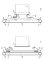
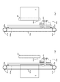
ストッパー片649a,649bまで搬送された冊子は、位置決め検知センサ626(図4参照)で検知される。また、前述のように、ストッパー片649a,649bの厚さ寸法は、厚い冊子の折り頂部が突き当たって位置決めできるように冊子の厚さよりも厚くなるように設定されている。このため、上下の押さえ板631,633の間にストッパー片649a,649bが位置するときは、上押さえ板633は冊子を固定できない関係となる。このため、図8(b)のように、冊子の位置決め後、ストッパー片649a,649bを上下の押さえ板631,633の脇に外してから、冊子の折り頂部近傍を押さえユニット630で挟圧保持する。このとき、冊子の折り頂部は上下押さえ板631,633の搬送方向下流側の端面から突出しない。なお、このとき冊子は搬送部620の上下搬送ベルト621,622により挟圧保持されているのでずれることはない。この後、厚さ検知センサ681で検知された冊子の厚さに応じて、図9(a)のように切替ユニット657でストッパー片649aから第1圧接片650、あるいは第2圧接片651に切り替える。図9(a)では第2圧接片651に切り替えた状態を例示している。そして、図9(b)、図10(a)のように、移動ユニット656aを反対側の冊子側端まで移動することで冊子の折り頂部を押し潰し、角付け処理する。そして、角付け処理された冊子は、図10(b)のように下流に搬送される。折り頂部の角付け処理された冊子を図3に示す。 The booklet conveyed to the stopper pieces 649a and 649b is detected by a positioning detection sensor 626 (see FIG. 4). Further, as described above, the thickness dimension of the stopper pieces 649a and 649b is set so as to be thicker than the thickness of the booklet so that the folded top portion of the thick booklet can be abutted and positioned. For this reason, when the stopper pieces 649a and 649b are positioned between the upper and lower pressing plates 631 and 633, the upper pressing plate 633 has a relationship in which the booklet cannot be fixed. For this reason, as shown in FIG. 8B, after the booklet is positioned, the stopper pieces 649a and 649b are removed to the sides of the upper and lower pressing plates 631 and 633, and the vicinity of the folding top portion of the booklet is held by the pressing unit 630. To do. At this time, the folded top portion of the booklet does not protrude from the end surface of the upper and lower pressing plates 631 and 633 on the downstream side in the transport direction. At this time, the booklet is held by the upper and lower conveying belts 621 and 622 of the conveying unit 620 so that it does not shift. Thereafter, according to the thickness of the booklet detected by the thickness detection sensor 681, the switching unit 657 switches from the stopper piece 649a to the first pressure contact piece 650 or the second pressure contact piece 651 as shown in FIG. 9A. . FIG. 9A illustrates the state switched to the second pressure contact piece 651. Then, as shown in FIGS. 9B and 10A, the moving unit 656a is moved to the booklet side end on the opposite side to crush the folded top portion of the booklet and perform the squaring process. Then, the booklet subjected to the squaring process is conveyed downstream as shown in FIG. FIG. 3 shows a booklet that has been subjected to the squaring process on the folded top portion.

図4に示すように、角付け処理部600において、搬送部660は、角付け処理され、押さえユニット630の挟持固定を解除された冊子を受け取り、下流へ搬送するための下搬送ベルト661、上搬送ベルト662で構成される。上搬送ベルト662は支点663を中心に冊子の厚さによって回動できるようになっており、下搬送ベルト661へバネ(不図示)により押圧されている。上下搬送ベルト661,662は搬送部620と駆動連結されており、モータSM4によって駆動する。   As shown in FIG. 4, in the squaring processing unit 600, the transport unit 660 receives a booklet that has been subjected to a squaring process and has been released from being clamped by the pressing unit 630, and is transported downstream, A conveyor belt 662 is used. The upper conveyor belt 662 can be rotated around the fulcrum 663 depending on the thickness of the booklet, and is pressed against the lower conveyor belt 661 by a spring (not shown). The upper and lower conveyor belts 661 and 662 are drivingly connected to the conveyor unit 620 and are driven by the motor SM4.

コンベアートレイ670は、搬送部660から排出される冊子を積載する。コンベアートレイ670の下面には、モータSM10の駆動を受けて搬送方向に移動するコンベアーベルト671が設けられ、冊子が排出される毎に所定量の移動を繰り返し、冊子の積載を行う。冊子が搬送部660から排出されたことの検知は、排出検知センサ664でなされる。   The conveyor tray 670 stacks the booklets discharged from the transport unit 660. On the lower surface of the conveyor tray 670, there is provided a conveyor belt 671 that moves in the conveying direction under the drive of the motor SM10, and repeats a predetermined amount of movement each time a booklet is ejected to stack the booklet. The detection that the booklet is discharged from the transport unit 660 is performed by the discharge detection sensor 664.

(制御部)
ここで、図11を用いて画像形成システムの制御系について説明する。図11は、画像形成システム1000の制御系の構成を示すブロック図である。CPU回路部150は、CPU(不図示)、ROM151、RAM152を有している。ROM151に格納された制御プログラム及び操作部1の設定に従い、原稿給送制御部101、イメージリーダ制御部201、画像信号制御部202、プリンタ制御部301、フィニッシャ制御部501、外部I/F203を制御する。そして、原稿給送制御部101は原稿給送部100を、イメージリーダ制御部201はイメージリーダ200を、プリンタ制御部301はプリンタ300を制御する。更に、フィニッシャ制御部501はフィニッシャ500、中綴じ製本部800、角付け処理制御部601はフィニッシャ制御部501からの指令に基づき角付け処理部600を制御する。
(Control part)
Here, the control system of the image forming system will be described with reference to FIG. FIG. 11 is a block diagram illustrating a configuration of a control system of the image forming system 1000. The CPU circuit unit 150 includes a CPU (not shown), a ROM 151, and a RAM 152. According to the control program stored in the ROM 151 and the setting of the operation unit 1, the document feeding control unit 101, the image reader control unit 201, the image signal control unit 202, the printer control unit 301, the finisher control unit 501, and the external I / F 203 are controlled. To do. The document feeding control unit 101 controls the document feeding unit 100, the image reader control unit 201 controls the image reader 200, and the printer control unit 301 controls the printer 300. Further, the finisher control unit 501 controls the squaring processing unit 600 based on a command from the finisher control unit 501, based on a command from the finisher control unit 501.

操作部1は、画像形成に関する各種機能を設定するための複数のキー、設定状態を表示するための表示部等を有する。操作部1は、ユーザーによる各キーの操作に対応するキー信号をCPU回路部150に出力すると共に、CPU回路部150からの信号に基づき対応する情報を表示部に表示する。   The operation unit 1 includes a plurality of keys for setting various functions relating to image formation, a display unit for displaying a setting state, and the like. The operation unit 1 outputs a key signal corresponding to the operation of each key by the user to the CPU circuit unit 150 and displays corresponding information based on the signal from the CPU circuit unit 150 on the display unit.

RAM152は、制御データを一時的に保持するための領域や、制御に伴う演算の作業領域として用いられる。外部I/F(外部インターフェース)203は、画像形成システム1000と外部のコンピュータ204とのインターフェースであり、コンピュータ204からのプリントデータをビットマップ画像に展開し、画像データとして画像信号制御部202へ出力する。また、イメージリーダ制御部201から画像信号制御部202へは、イメージセンサ109で読み取った原稿の画像が出力される。プリンタ制御部301は、画像信号制御部202からの画像データを露光制御部110へ出力する。   The RAM 152 is used as an area for temporarily storing control data and a work area for operations associated with control. An external I / F (external interface) 203 is an interface between the image forming system 1000 and an external computer 204. The print data from the computer 204 is expanded into a bitmap image and output to the image signal control unit 202 as image data. To do. An image of the original read by the image sensor 109 is output from the image reader control unit 201 to the image signal control unit 202. The printer control unit 301 outputs the image data from the image signal control unit 202 to the exposure control unit 110.

図12は角付け処理制御部601のブロック図であり、前述した各駆動モータSM1,SM2,SM3,SM4,SM5,SM6,SM7,SM8,SM10を制御するようになっている。   FIG. 12 is a block diagram of the squaring processing control unit 601, which controls the drive motors SM1, SM2, SM3, SM4, SM5, SM6, SM7, SM8, and SM10.

(角付け処理動作)
次に、上記構成に基づき、角付け処理部600における角付け(変形)処理動作について冊子の流れと共に各部の動作を説明する。
(Chamfer processing operation)
Next, based on the above configuration, regarding the squaring (deformation) processing operation in the squaring processing unit 600, the operation of each unit will be described together with the flow of the booklet.

操作部1において、中綴じモードが選択されると、角付け処理モードを設定するか否かを選択できるようになる。   When the saddle stitching mode is selected in the operation unit 1, it is possible to select whether or not to set the squaring process mode.

角付け処理モードが選択されなかった場合は、中綴じ製本部800で作成された中綴じ冊子は、下搬送ベルト611、搬送爪613、搬送部620、搬送部660によって、コンベアートレイ670に排出される。このとき、サイドガイド対612、上押さえ板633、移動ユニット656a,656bは、搬送路をさえぎらない位置に待避している。   When the squaring process mode is not selected, the saddle stitch booklet created by the saddle stitch bookbinding unit 800 is discharged to the conveyor tray 670 by the lower conveyance belt 611, the conveyance claw 613, the conveyance unit 620, and the conveyance unit 660. The At this time, the pair of side guides 612, the upper pressing plate 633, and the moving units 656a and 656b are retracted to positions that do not block the conveyance path.

角付け処理モードが選択された場合の動作については以下に詳細に説明する。図13、図14、図15は角付け処理モードが選択された場合の動作の流れを示すフローチャートである。   The operation when the squaring process mode is selected will be described in detail below. FIGS. 13, 14, and 15 are flowcharts showing the flow of operations when the squaring process mode is selected.

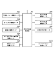
角付け処理モードが選択されると、図13のように、角付け処理部600はイニシャル動作をする(S1)。中綴じ製本部800で冊子が作成されると、第2折り搬送ローラ対812によって角付け処理部600の受け取り部610に排出される前に、冊子のシート枚数、シートサイズ、作成する冊子数を角付け処理制御部601へ通知する(S2)。角付け処理制御部601は、冊子Sのシート枚数が11枚以上であるかを判断する(S3)。角付け処理制御部601は通知された冊子のシートの枚数が10枚以下であった場合(NO)は角付け処理無しモードを選択し(S4)、11枚以上であった場合(YES)は角付け処理有りモードを選択する(S5)。   When the squaring processing mode is selected, as shown in FIG. 13, the squaring processing unit 600 performs an initial operation (S1). When a booklet is created by the saddle stitch bookbinding unit 800, the number of sheets of the booklet, the sheet size, and the number of booklets to be created are set before being discharged to the receiving unit 610 of the squaring processing unit 600 by the second folding conveyance roller pair 812. The squaring process control unit 601 is notified (S2). The squaring process control unit 601 determines whether the number of sheets of the booklet S is 11 or more (S3). The squaring process control unit 601 selects the no squaring process mode when the notified number of sheets of the booklet is 10 or less (NO) (S4), and when it is 11 or more (YES). A mode with squaring processing is selected (S5).

冊子のシートの枚数が10枚以下であり、角付け処理無しモードが選択された場合は、図14のフローとなる。   When the number of sheets of the booklet is 10 or less and the mode without squaring process is selected, the flow is as shown in FIG.

受け取り部610の搬送経路の両側に配設されたサイドガイド対612が冊子サイズに合わせて待機位置へ移動する(S21)。中綴じ製本部800からの排出通知を受けると(S22)、下搬送ベルト611が駆動モータSM1によって回転し(S23)、冊子を搬送する。入口検知センサ615、出口検知センサ616で冊子を検知(S24,25)した後、冊子の搬送を一旦停止する(S26)。その後、サイドガイド対612が駆動モータSM12により整合動作を行う(S27)。その後、駆動モータSM4によって、搬送部620および搬送部660が駆動され(S28)、受け取り部610の上流に配置された搬送爪613と下搬送ベルト611によって、冊子の搬送が再開される(S29)。搬送爪613は駆動モータSM13で駆動される。そして、出口検知センサ616で冊子の排出を検知する(S30)と搬送爪613は搬送方向上流に退避する(S31)。搬送部620および搬送部660で搬送された冊子がコンベアートレイ670へ排出され、排出検知センサ664で排出検知される(S32)と、搬送部620および搬送部660が駆動を停止する(S33)。コンベアートレイ670へ排出された冊子は、順次瓦積み状に重ねられていく。排出された冊子が最終冊子でなければS21へ戻り、最終冊子であればジョブを終了する(S34,35)。   The side guide pairs 612 disposed on both sides of the conveyance path of the receiving unit 610 move to the standby position according to the booklet size (S21). When receiving a discharge notification from the saddle stitch bookbinding section 800 (S22), the lower conveyor belt 611 is rotated by the drive motor SM1 (S23), and the booklet is conveyed. After the booklet is detected by the inlet detection sensor 615 and the outlet detection sensor 616 (S24, 25), the conveyance of the booklet is temporarily stopped (S26). Thereafter, the side guide pair 612 performs alignment operation by the drive motor SM12 (S27). Thereafter, the conveyance unit 620 and the conveyance unit 660 are driven by the drive motor SM4 (S28), and the conveyance of the booklet is resumed by the conveyance claw 613 and the lower conveyance belt 611 disposed upstream of the reception unit 610 (S29). . The conveyance claw 613 is driven by a drive motor SM13. When the exit detection sensor 616 detects the discharge of the booklet (S30), the transport claw 613 is retracted upstream in the transport direction (S31). When the booklet conveyed by the conveyance unit 620 and the conveyance unit 660 is discharged to the conveyor tray 670 and detected by the discharge detection sensor 664 (S32), the conveyance unit 620 and the conveyance unit 660 stop driving (S33). The booklets discharged to the conveyor tray 670 are sequentially stacked in a tiled shape. If the discharged booklet is not the final booklet, the process returns to S21, and if it is the final booklet, the job is terminated (S34, 35).

一方、冊子のシートの枚数が11枚以上であり、角付け処理有りモードが選択された場合は、図15のフローとなる。   On the other hand, when the number of sheets of the booklet is 11 or more and the squaring processing mode is selected, the flow of FIG. 15 is performed.

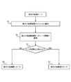
受け取り部610の搬送経路の両側に配設されたサイドガイド対612が冊子サイズに合わせて待機位置へ移動する。それとともに、切替ユニット657によってストッパー片649aに切り替えられ、移動ユニット656a,656bが位置決め位置へ移動する(S51)。位置決め位置は冊子のサイズによって変わり、冊子の折り頂部がストッパー片649a,649bに突き当たったときに回転したりせず、移動ユニット656a,656bの移動方向に対して冊子の折り頂部の平行が維持される位置に設定されている。中綴じ製本部800からの排出通知を受けると(S52)、下搬送ベルト611が駆動モータSM1によって回転し(S53)、冊子を搬送する。入口検知センサ615、出口検知センサ616で冊子を検知(S54、55)した後、冊子の搬送を一旦停止する(S56)。   The side guide pairs 612 disposed on both sides of the conveyance path of the receiving unit 610 move to the standby position according to the booklet size. At the same time, the switching unit 657 switches to the stopper piece 649a, and the moving units 656a and 656b move to the positioning positions (S51). The positioning position varies depending on the size of the booklet. The booklet does not rotate when the folded top of the booklet hits the stopper pieces 649a and 649b, and the booklet folded top is kept parallel to the moving direction of the moving units 656a and 656b. The position is set. When receiving a discharge notification from the saddle stitch bookbinding unit 800 (S52), the lower conveyance belt 611 is rotated by the drive motor SM1 (S53), and the booklet is conveyed. After the booklet is detected by the inlet detection sensor 615 and the outlet detection sensor 616 (S54, 55), the conveyance of the booklet is temporarily stopped (S56).

その後、サイドガイド対612が駆動モータSM12により整合動作を行う(S57)。その後、駆動モータSM4によって、搬送部620および搬送部660が駆動され(S58)、受け取り部610の上流に配置された搬送爪613と下搬送ベルト611によって、冊子の搬送が再開される(S59)。搬送爪613は駆動モータSM13で駆動される。そして、出口検知センサ616で冊子の排出を検知する(S60)と搬送爪613は搬送方向上流に退避する(S61)。搬送部620で搬送された冊子が位置決め検知センサ626で検知される(S62)と、搬送部620の駆動が停止する(S63)。このとき、図16のように、冊子の折り頂部がストッパー片649a,649bに突き当たり、上下の押さえ板631,632の保持面間の搬送方向下端から出っ張らない位置に位置決めされている。   Thereafter, the side guide pair 612 performs alignment operation by the drive motor SM12 (S57). Thereafter, the conveyance motor 620 and the conveyance unit 660 are driven by the drive motor SM4 (S58), and the conveyance of the booklet is resumed by the conveyance claw 613 and the lower conveyance belt 611 arranged upstream of the reception unit 610 (S59). . The conveyance claw 613 is driven by a drive motor SM13. When the exit detection sensor 616 detects the discharge of the booklet (S60), the transport claw 613 is retracted upstream in the transport direction (S61). When the booklet conveyed by the conveyance unit 620 is detected by the positioning detection sensor 626 (S62), the driving of the conveyance unit 620 is stopped (S63). At this time, as shown in FIG. 16, the folded top portion of the booklet hits the stopper pieces 649 a and 649 b and is positioned at a position where it does not protrude from the lower end in the transport direction between the holding surfaces of the upper and lower pressing plates 631 and 632.

次に、移動ユニット656a,656bが上下の押さえ板631,633の保持面間から外れた位置(上下の押さえ板631,633の脇に位置)のにある待機位置に移動する(S64)。そして、駆動モータSM5により押さえベース632が下位置に移動し(S65)、上下押さえ板631,633の対向する保持面により冊子の折り頂部が固定される。次に、冊子を固定した状態の上押さえ板633の位置が厚さ検知センサ681により検知され(S66)、これにより冊子の厚さが測定される。冊子の厚さが前述のT2からT3の範囲であった場合は第1圧接片650に切り替えられ、T4からT5の範囲であった場合は第2圧接片651に切り替えられる(S67)。そして、移動ユニット656aを冊子の折り頂部に沿って移動(S68)することで、冊子の折り頂部の角付け処理がなされる。なお、図17は、第1圧接片650で冊子Sの折り頂部を角付け処理している図である。図18は、第2圧接片651で冊子Sの折り頂部を角付け処理している図である。   Next, the moving units 656a and 656b move to a standby position located at a position (side of the upper and lower pressing plates 631 and 633) that is out of the holding surfaces of the upper and lower pressing plates 631 and 633 (S64). Then, the pressing base 632 is moved to the lower position by the drive motor SM5 (S65), and the folding top portion of the booklet is fixed by the opposing holding surfaces of the upper and lower pressing plates 631, 633. Next, the position of the upper presser plate 633 with the booklet fixed is detected by the thickness detection sensor 681 (S66), thereby measuring the thickness of the booklet. When the thickness of the booklet is in the range from T2 to T3, the first pressure contact piece 650 is switched, and when the booklet is in the range from T4 to T5, the second pressure contact piece 651 is switched (S67). Then, the moving unit 656a is moved along the folding top portion of the booklet (S68), so that the cornering processing of the folding top portion of the booklet is performed. Note that FIG. 17 is a view in which the folding top portion of the booklet S is squared with the first pressure contact piece 650. FIG. 18 is a diagram in which the folding top portion of the booklet S is squared with the second pressure contact piece 651.

このように、冊子の折り頂部は上下の押さえ板631,632の内側(保持面間)で挟圧保持されるので、その折り頂部を潰して角付け処理する際に、折り頂部が上下の押さえ板631,632の端面(角部)に当接することはなく、圧接痕がつくことはない。   In this way, the folding top of the booklet is held between the upper and lower pressing plates 631, 632 (between the holding surfaces), so that when the folding top is crushed and squared, There is no contact with the end faces (corner portions) of the plates 631 and 632, and no pressure contact marks are formed.

また、冊子の折り頂部は上下の押さえ板631,632と第1圧接片650または第2圧接片651で囲まれているため、必要以上の圧接力が加えられることはなく、冊子の厚さと略等しい幅の平滑面が形成される。また、冊子中心のシート折り頂部をも変形させるほどの作用は働かず、内側から順に折り頂部が角付けされた、見栄えの良い冊子を作成することができる。   Further, the folding top of the booklet is surrounded by the upper and lower pressing plates 631 and 632 and the first press contact piece 650 or the second press contact piece 651, so that an excessive press force is not applied, and the thickness of the booklet is substantially the same. A smooth surface of equal width is formed. In addition, the function of deforming the sheet folding top part at the center of the booklet does not work, and it is possible to create a good-looking booklet in which the folding top part is rounded in order from the inside.

移動ユニット656aの移動が完了すると、押さえベース632が上位置へ移動し(S69)、上下押さえ板631,633が離間し、対向する保持面による冊子の挟圧保持が解除される。そして、搬送部620、搬送部660が駆動モータSM4により駆動され(S70)、冊子がコンベアートレイ670へ排出される。この冊子が、排出検知センサ664で排出検知される(S71)と、搬送部620、搬送部660が駆動を停止する(S72)。コンベアートレイ670へ排出された冊子は、順次瓦積み状に重ねられていく。排出された冊子が最終冊子でなければSTEP51へ戻り、最終冊子であればジョブを終了する(S73,74)。   When the movement of the moving unit 656a is completed, the pressing base 632 is moved to the upper position (S69), the upper and lower pressing plates 631 and 633 are separated, and the holding of the booklet by the holding surfaces facing each other is released. Then, the transport unit 620 and the transport unit 660 are driven by the drive motor SM4 (S70), and the booklet is discharged to the conveyor tray 670. When the booklet is detected by the discharge detection sensor 664 (S71), the transport unit 620 and the transport unit 660 stop driving (S72). The booklets discharged to the conveyor tray 670 are sequentially stacked in a tiled shape. If the discharged booklet is not the final booklet, the process returns to STEP 51, and if it is the final booklet, the job is terminated (S73, 74).

[第2実施形態]
第1の実施形態では冊子の厚さに応じて厚さと直径の異なる圧接片を切り替えて角付け(変形)処理する場合について述べたが、本第2実施形態では、冊子の厚さに応じて厚さは異なるが、直径が同じ圧接片を用いた場合について説明する。なお、本第2実施形態において、上記第1実施形態と同一の構成については、同一符号を付して説明を省略する。図19は、本発明の第2の実施形態における保持部材対の保持面間の間隔と各片の関係を示す要部拡大図である。
[Second Embodiment]
In the first embodiment, the case has been described in which the press-contacting pieces having different thicknesses and diameters are switched according to the thickness of the booklet, and the squaring (deformation) processing is performed. the thickness differ Te will describe a case where the diameter is using the same pressing member. Note that in the second embodiment, the same components as those in the first embodiment are denoted by the same reference numerals and description thereof is omitted. FIG. 19 is an enlarged view of a main part showing the relationship between the distance between the holding surfaces of the holding member pair and each piece in the second embodiment of the present invention.

図19に示すように、本実施の形態において、圧接片850と圧接片851は、厚さにおいてはH2とH3とで異なっているが、直径はD4で同じである。本実施の形態では、冊子の厚さがT2〜T3の場合は圧接片850で、冊子の厚さがT4〜T5の場合は圧接片851で、それぞれ角付け処理し、変形領域(圧接量)は同じP4とする。このように、冊子厚さに関わらず変形領域(圧接量)が同じであるので、でき上がった冊子の背から小口までの寸法に差がなくなる。第1実施形態に比べて角付け処理可能な冊子の厚さ範囲が狭く設定されている場合には、薄い冊子の過度の変形や厚い冊子の変形不足を回避する必要がないため、均一な変形領域(圧接量)を設定することができる。 As shown in FIG. 19, in the present embodiment, the pressure contact piece 850 and the pressure contact piece 851 are different in thickness between H2 and H3, but the diameter is the same as D4. In this embodiment, when the thickness of the booklet is T2 to T3, the press contact piece 850 is used, and when the thickness of the booklet is T4 to T5, the press contact piece 851 is used for the squaring process, respectively, and the deformation region (pressure contact amount) Are the same P4. Thus, since the deformation area (pressure contact amount) is the same regardless of the booklet thickness, there is no difference in the dimensions from the back to the fore edge of the completed booklet. Compared to the first embodiment, when the thickness range of the booklet that can be squared is set to be narrow, it is not necessary to avoid excessive deformation of a thin booklet or insufficient deformation of a thick booklet. A region (pressure contact amount) can be set.

ここでは、冊子の厚さを2つの範囲に分け、2種類の厚さの異なる圧接片を使用した例を述べたが、これに限定されるものではない。第1実施形態同様、冊子の厚さの場合分けを3つ4つとさらに細かくして使用する圧接片の種類を増やしてもよい。 Here, an example in which the thickness of the booklet is divided into two ranges and two types of pressure contact pieces having different thicknesses are used is described, but the present invention is not limited to this. As in the first embodiment, the number of types of press contact pieces to be used may be increased by further dividing the booklet thickness into three and four.

[第3実施形態]
上述した実施形態においては、冊子の厚さを検知する厚さ検知センサ681は、図4(b)に示すように、反射光量を電流値に換算して距離を測定する測距センサであったが、図20に示すような検知手段であっても良い。図20(a)は、本発明の第3の実施形態における冊子の厚さを検知する構成例である。図20(a)は、上下の押さえ板631,633を離間させ、冊子の挟持固定を解除した状態を示す要部断面図である。図20(b)は上下の押さえ板631,633で冊子を挟持固定した状態を示す要部断面図である。
[Third Embodiment]
In the embodiment described above, the thickness detection sensor 681 that detects the thickness of the booklet is a distance measurement sensor that measures the distance by converting the amount of reflected light into a current value, as shown in FIG. However, a detection means as shown in FIG. 20 may be used. FIG. 20A is a configuration example for detecting the thickness of a booklet according to the third embodiment of the present invention. FIG. 20A is a cross-sectional view of the main part showing a state in which the upper and lower pressing plates 631 and 633 are separated from each other and the booklet is nipped and fixed. FIG. 20B is a cross-sectional view of the main part showing a state where the booklet is sandwiched and fixed by the upper and lower pressing plates 631 and 633.

図20では、厚さ検知センサ681は、反射式センサであり、上押さえ板633の一端部に設けられている。厚さ検知センサ681と対向した位置には、下押さえ板631から延長されたスリット板682が固定されている。スリット板682は、上押さえ板633の昇降方向にスリットが等間隔で刻設されたものである。厚さ検知センサ681は、上押さえ板633の昇降動作に連動し、ONとOFFを繰り返す。ONから次のON、またはOFFから次のOFFまでを1パルスとしてカウントし、上押さえ板633と下押さえ板631との距離を検出することができる。 In FIG. 20, the thickness detection sensor 681 is a reflective sensor and is provided at one end of the upper pressing plate 633 . A slit plate 682 extending from the lower presser plate 631 is fixed at a position facing the thickness detection sensor 681. The slit plate 682 has slits formed at equal intervals in the up-and-down direction of the upper pressing plate 633 . The thickness detection sensor 681 is repeatedly turned ON and OFF in conjunction with the lifting operation of the upper pressing plate 633. From ON to the next ON or from OFF to the next OFF is counted as one pulse, and the distance between the upper pressing plate 633 and the lower pressing plate 631 can be detected.

たとえば、押さえベース632が上死点検知センサ639で検出される上位置のとき、上下の押さえ板の間隔をLとする。ここから下降して、冊子Sを把持するまでのパルス数をNとする。1パルスの距離をPとすると、冊子Sの厚さTは、T=L−N×Pで表すことができる。このようにして冊子Sの厚さTは検出され、この情報を元に、圧接片の切り替え処理がなされる。   For example, when the pressing base 632 is in the upper position detected by the top dead center detection sensor 639, the interval between the upper and lower pressing plates is set to L. Let N be the number of pulses that descend from here until the booklet S is gripped. When the distance of one pulse is P, the thickness T of the booklet S can be expressed as T = L−N × P. In this way, the thickness T of the booklet S is detected, and the pressure contact piece switching process is performed based on this information.

[その他の実施形態]
また、上述した実施形態では、センサを用いて冊子の厚さを検出していたが、センサを用いずに冊子の厚さを算出して、その算出値(冊子の厚さ)に基づいて動作を制御するようにしても良い。この場合、操作者は、カセット114,115、手差し給送部125に収納されているシートの情報(例えば坪量)を操作部(入力手段)1から入力し、RAM152に記憶させる。入力された坪量(52g/m〜200g/m)は、複数のカテゴリーに分けられ、各カテゴリー毎に、シート1枚あたりの厚さMが実測値を元に割り当てられる。シート束1束分のシート枚数Nは、イメージ数により決まり、CPU回路部150は、シートの枚数Nとシートの厚さMを乗じて、シート束の厚さを演算する。中綴じ冊子はシート束を2つ折りしたものであり、シート束の厚さMを2倍したものである。このように冊子を形成するシートの情報を元にして、冊子の厚さが算出され、この情報を元に、圧接片の切り替え処理がなされる。なお、この場合、図15の(STEP66)は、『CPU回路部150による冊子厚の算出』に置き換わる。
[Other Embodiments]
In the above-described embodiment, the thickness of the booklet is detected using the sensor, but the thickness of the booklet is calculated without using the sensor, and the operation is performed based on the calculated value (the thickness of the booklet). May be controlled. In this case, the operator inputs information (for example, basis weight) of sheets stored in the cassettes 114 and 115 and the manual feeding unit 125 from the operation unit (input unit) 1 and stores the information in the RAM 152. The basis weight input (52g / m 2 ~200g / m 2) is divided into a plurality of categories, each category, the thickness M per one sheet is assigned based on the measured values. The number of sheets N for one sheet bundle is determined by the number of images, and the CPU circuit unit 150 multiplies the number N of sheets and the sheet thickness M to calculate the thickness of the sheet bundle. The saddle-stitched booklet is obtained by folding a sheet bundle in two, and is obtained by doubling the thickness M of the sheet bundle. In this way, the thickness of the booklet is calculated based on the information on the sheets forming the booklet, and the pressing piece switching process is performed based on this information. In this case, (STEP 66) in FIG. 15 is replaced with “calculation of booklet thickness by the CPU circuit unit 150”.

また、上述した実施形態においては、中綴じ製本部800で作成される冊子をシート1枚から25枚までの二つ折りした冊子として説明したが、中綴じ製本部の能力によってシート枚数を変えてもよい。また、角付け処理される冊子を11枚以上のシートを二つ折りした冊子として説明したが、メディア(シート)の坪量や厚さによって冊子のシート枚数を変更してもよく、本発明を何ら限定するものではない。   In the above-described embodiment, the booklet created by the saddle stitch bookbinding unit 800 is described as a booklet folded in half from 1 sheet to 25 sheets, but the number of sheets may be changed depending on the ability of the saddle stitch bookbinding unit. Good. Further, although the booklet to be squared has been described as a booklet in which 11 or more sheets are folded in half, the number of sheets of the booklet may be changed depending on the basis weight or thickness of the medium (sheet). It is not limited.

また、上述した実施形態においては、角付け処理される冊子の厚さによって2つに場合わけし、2種類の厚さと直径の違う圧接片を使用して角付け処理するように説明したが、これに限定されるものではない。例えば、場合分けをより細かくして使用する圧接片の種類を増やしてもよく、本発明を何ら限定するものではない。 Further, in the above-described embodiment, there are two cases depending on the thickness of the booklet to be squared, and the description has been made so that the squabing process is performed using two types of pressure contact pieces having different thicknesses and diameters. However, the present invention is not limited to this. For example, the types of pressure contact pieces to be used may be increased with finer classification, and the present invention is not limited in any way.

また、上述した実施形態においては、冊子の厚さをセンサで検知して場合分けしたが、メディア(シート)の坪量、厚さ、シート枚数など、冊子の厚さを決め得る条件から場合分けを行ってもよい。   In the above-described embodiment, the thickness of the booklet is detected by a sensor, and the case is classified. However, the case is determined based on conditions that can determine the thickness of the booklet, such as the basis weight, thickness, and number of sheets of the media (sheet). May be performed.

また、上述した実施形態では、画像形成装置として複写機を例示したが、本発明はこれに限定されるものではなく、例えばプリンタ、ファクシミリ装置等の他の画像形成装置や、或いはこれらの機能を組み合わせた複合機等の他の画像形成装置であっても良い。これらの画像形成装置に用いられるシート処理装置に本発明を適用することにより同様の効果を得ることができる。   Further, in the above-described embodiment, the copying machine is exemplified as the image forming apparatus. However, the present invention is not limited to this, and other image forming apparatuses such as a printer and a facsimile apparatus, or their functions are provided. Another image forming apparatus such as a combined multifunction peripheral may be used. The same effect can be obtained by applying the present invention to a sheet processing apparatus used in these image forming apparatuses.

また、上述した実施形態では、画像形成装置に対して着脱可能なシート処理装置を例示したが、本発明はこれに限定されるものではない。例えば画像形成装置が一体的に有するシート処理装置であっても良く、該シート処理装置に本発明を適用することにより同様の効果を得ることができる。   In the above-described embodiment, the sheet processing apparatus that can be attached to and detached from the image forming apparatus has been illustrated, but the present invention is not limited to this. For example, the image forming apparatus may be a sheet processing apparatus that is integrally provided, and the same effects can be obtained by applying the present invention to the sheet processing apparatus.

S,S1,S2,S3 …冊子
10 …画像形成装置本体
20 …シート処理装置
600 …角付け処理部
630 …押さえユニット
631 …下押さえ板
632 …押さえベース
633 …上押さえ板
640 …角付けユニット
649a,649b …ストッパー片
650 …第1圧接片
651 …第2圧接片
656a,656b …移動ユニット
657 …切替ユニット
681 …厚さ検知センサ
800 …中綴じ製本部
1000 …画像形成システム
S, S1, S2, S3 ... Booklet 10 ... Image forming apparatus main body 20 ... Sheet processing apparatus 600 ... Cornering processing unit 630 ... Holding unit 631 ... Lower pressing plate 632 ... Pressing base 633 ... Upper pressing plate 640 ... Cornering unit 649a , 649b ... stopper piece 650 ... first press contact piece 651 ... second press contact piece 656a, 656b ... moving unit 657 ... switching unit 681 ... thickness detection sensor 800 ... saddle stitch bookbinding part 1000 ... image forming system

Claims (8)

折り畳まれたシートからなる冊子を対向する保持部材対で挟圧して保持する保持手段と、
前記保持部材対間に進入して前記保持された冊子の折り頂部に圧接して前記冊子の折り頂部を変形処理する圧接手段と、
を有し、
前記圧接手段は、冊子の厚さ方向の厚さが異なる複数の圧接部材を有し、前記複数の圧接部材のうち前記保持部材対間に進入可能で、前記保持部材対に挟圧保持された冊子の厚さに最も近い厚さを有する圧接部材を選択して変形処理を行うことを特徴とするシート処理装置。
Holding means for holding and holding a booklet made of a folded sheet with a holding member pair facing each other;
Pressure contact means that enters between the pair of holding members and press-contacts the folded top portion of the held booklet to deform the folded top portion of the booklet;
Have
The press contact means includes a plurality of press contact members having different thicknesses in the thickness direction of the booklet, and is capable of entering between the holding member pairs among the plurality of press contact members, and is sandwiched and held between the holding member pairs. A sheet processing apparatus that performs deformation processing by selecting a press-contact member having a thickness closest to the thickness of a booklet.
冊子の厚さを検知する厚さ検知手段を有し、前記厚さ検知手段が検知した冊子の厚さに応じて、前記圧接部材の切り替えを行うことを特徴とする請求項1に記載のシート処理装置。   2. The sheet according to claim 1, further comprising a thickness detecting unit that detects a thickness of the booklet, wherein the pressing member is switched according to the thickness of the booklet detected by the thickness detecting unit. Processing equipment. 前記厚さ検知手段は、前記保持部材対間の間隔を測定することにより前記保持部材対に挟圧保持された冊子の厚さを検知することを特徴とする請求項2に記載のシート処理装置。   3. The sheet processing apparatus according to claim 2, wherein the thickness detection unit detects a thickness of a booklet held between the holding member pairs by measuring an interval between the holding member pairs. 4. . 前記冊子の折り頂部を所定の位置に位置決めする位置決め手段を備え、前記圧接手段は、前記位置決め手段により位置決めされた前記冊子の折り頂部に圧接することを特徴とする請求項1乃至請求項3のいずれか1項に記載のシート処理装置。   4. The positioning device according to claim 1, further comprising positioning means for positioning the folded top portion of the booklet at a predetermined position, wherein the pressing means is in pressure contact with the folded top portion of the booklet positioned by the positioning means. The sheet processing apparatus according to claim 1. 前記位置決め手段は、前記冊子の折り頂部が当接する位置決め部材を有し、前記位置決め部材の前記所定の位置への進入量は、前記圧接部材の前記保持部材対間への進入量よりも小さいことを特徴とする請求項4に記載のシート処理装置。 The positioning means includes a positioning member with which the folded top portion of the booklet abuts, and an amount of the positioning member entering the predetermined position is smaller than an amount of the pressure contact member entering between the holding member pair. The sheet processing apparatus according to claim 4. 前記複数の圧接部材は、前記保持部材対に挟圧保持された冊子の折り頂部に沿って移動しながら前記冊子の折り頂部に圧接する回転体であることを特徴とする請求項1乃至請求項5のいずれか1項に記載のシート処理装置。The plurality of press-contacting members are rotating bodies that press-contact the folded top portion of the booklet while moving along the folded top portion of the booklet held by the holding member pair. The sheet processing apparatus according to claim 5. シートに画像を形成する画像形成部と、画像が形成されたシートに対して選択的に処理を行う、請求項1乃至請求項のいずれか1項に記載のシート処理装置と、を有することを特徴とする画像形成装置。 An image forming unit for forming an image on a sheet, the image is selectively perform processing on the formed sheet, having a sheet processing apparatus according to any one of claims 1 to 6 An image forming apparatus. 冊子を形成するシートに画像を形成する画像形成部と、画像を形成されるシートの情報を入力する入力手段と、入力された情報を元に算出された冊子の厚さに応じて、前記圧接部材の切り替えを行う、請求項1に記載のシート処理装置と、を有することを特徴とする画像形成システム。   An image forming unit that forms an image on a sheet that forms a booklet, an input unit that inputs information about the sheet on which the image is formed, and the pressure contact according to the thickness of the booklet calculated based on the input information. An image forming system comprising: the sheet processing apparatus according to claim 1, wherein the member is switched.
JP2009233000A 2009-10-07 2009-10-07 Sheet processing apparatus, image forming apparatus, and image forming system Expired - Fee Related JP5377210B2 (en)

Priority Applications (2)

Application Number Priority Date Filing Date Title
JP2009233000A JP5377210B2 (en) 2009-10-07 2009-10-07 Sheet processing apparatus, image forming apparatus, and image forming system
US12/890,189 US8231120B2 (en) 2009-10-07 2010-09-24 Sheet processing apparatus, image forming apparatus, and image forming system

Applications Claiming Priority (1)

Application Number Priority Date Filing Date Title
JP2009233000A JP5377210B2 (en) 2009-10-07 2009-10-07 Sheet processing apparatus, image forming apparatus, and image forming system

Publications (3)

Publication Number Publication Date
JP2011079213A JP2011079213A (en) 2011-04-21
JP2011079213A5 JP2011079213A5 (en) 2013-09-19
JP5377210B2 true JP5377210B2 (en) 2013-12-25

Family

ID=43823284

Family Applications (1)

Application Number Title Priority Date Filing Date
JP2009233000A Expired - Fee Related JP5377210B2 (en) 2009-10-07 2009-10-07 Sheet processing apparatus, image forming apparatus, and image forming system

Country Status (2)

Country Link
US (1) US8231120B2 (en)
JP (1) JP5377210B2 (en)

Families Citing this family (4)

* Cited by examiner, † Cited by third party
Publication number Priority date Publication date Assignee Title
US9445971B2 (en) * 2012-05-01 2016-09-20 Johnson & Johnson Consumer Inc. Method of manufacturing solid dosage form
JP6218595B2 (en) 2013-12-25 2017-10-25 キヤノン株式会社 Sheet processing apparatus and image forming apparatus
JP6362082B2 (en) 2014-04-30 2018-07-25 キヤノン株式会社 Sheet processing apparatus and image forming apparatus
JP2018008778A (en) 2016-07-13 2018-01-18 キヤノン株式会社 Sheet processing device

Family Cites Families (13)

* Cited by examiner, † Cited by third party
Publication number Priority date Publication date Assignee Title
US5443248A (en) 1992-06-29 1995-08-22 Canon Kabushiki Kaisha Sheet post-processing apparatus
US5951000A (en) 1994-03-18 1999-09-14 Canon Kabushiki Kaisha Sheet post-processing apparatus
JP3214656B2 (en) 1995-03-31 2001-10-02 キヤノン株式会社 Sheet post-processing apparatus and image forming apparatus having the same
GB0005333D0 (en) 2000-03-07 2000-04-26 Watkiss Automation Ltd Methods of and apparatus for producing booklets
JP4164454B2 (en) * 2004-02-27 2008-10-15 キヤノン株式会社 Sheet processing apparatus and image forming apparatus
JP4560413B2 (en) * 2004-02-27 2010-10-13 キヤノン株式会社 Sheet bundle back folding unit flat processing apparatus, sheet processing apparatus, and image forming apparatus
JP4217654B2 (en) * 2004-04-12 2009-02-04 キヤノン株式会社 Sheet back folding unit flat processing apparatus and image forming apparatus including the apparatus
JP4759345B2 (en) 2005-08-31 2011-08-31 キヤノン株式会社 Sheet processing apparatus and image forming apparatus
JP4760279B2 (en) * 2005-10-07 2011-08-31 富士ゼロックス株式会社 Folding part flattening device
JP5142658B2 (en) 2006-10-26 2013-02-13 キヤノン株式会社 Bookbinding apparatus and image forming apparatus provided with the same
JP5473502B2 (en) * 2009-03-16 2014-04-16 キヤノン株式会社 Sheet processing apparatus and image forming apparatus having the same
JP2010241112A (en) * 2009-03-18 2010-10-28 Ricoh Co Ltd Spine formation device, saddle-stitch bookbinding apparatus, sheet-edge cutting apparatus, sheet processing apparatus, and image forming apparatus
JP2011005711A (en) * 2009-06-25 2011-01-13 Canon Inc Sheet processor

Also Published As

Publication number Publication date
US20110081184A1 (en) 2011-04-07
US8231120B2 (en) 2012-07-31
JP2011079213A (en) 2011-04-21

Similar Documents

Publication Publication Date Title
JP4724508B2 (en) Sheet processing apparatus and image forming apparatus
JP5473502B2 (en) Sheet processing apparatus and image forming apparatus having the same
JP5455671B2 (en) Sheet processing apparatus and image forming apparatus
JP5284060B2 (en) Sheet processing apparatus and image forming apparatus
JP5178776B2 (en) Sheet processing apparatus and image forming apparatus
JP5610780B2 (en) Sheet post-processing apparatus and image forming apparatus
JP2010036333A (en) Sheet processing device and image forming device
JP5528099B2 (en) Sheet post-processing apparatus and image forming apparatus having the same
JP5377210B2 (en) Sheet processing apparatus, image forming apparatus, and image forming system
JP5349924B2 (en) Sheet processing apparatus and image forming apparatus
JP5465139B2 (en) Sheet processing apparatus and image forming system
JP5464962B2 (en) Sheet processing apparatus and image forming system
JP5535123B2 (en) Sheet processing apparatus and image forming apparatus
JP5464921B2 (en) Sheet processing apparatus and image forming apparatus
JP5534827B2 (en) Sheet post-processing apparatus and image forming apparatus
JP4986825B2 (en) Sheet processing apparatus and image forming apparatus
JP2011005711A (en) Sheet processor
JP5322573B2 (en) Sheet processing apparatus and image forming apparatus
JP5511499B2 (en) Sheet processing apparatus and image forming apparatus
JP2007045621A (en) Sheet processor
JP2011079631A (en) Sheet processing device and image forming system
JP2011148100A (en) Sheet processing apparatus and image forming system
JP2012056107A (en) Sheet handling device, and method for controlling the same

Legal Events

Date Code Title Description
A521 Written amendment

Free format text: JAPANESE INTERMEDIATE CODE: A523

Effective date: 20120913

A621 Written request for application examination

Free format text: JAPANESE INTERMEDIATE CODE: A621

Effective date: 20120913

A977 Report on retrieval

Free format text: JAPANESE INTERMEDIATE CODE: A971007

Effective date: 20130808

A521 Written amendment

Free format text: JAPANESE INTERMEDIATE CODE: A523

Effective date: 20130809

TRDD Decision of grant or rejection written
A01 Written decision to grant a patent or to grant a registration (utility model)

Free format text: JAPANESE INTERMEDIATE CODE: A01

Effective date: 20130827

A61 First payment of annual fees (during grant procedure)

Free format text: JAPANESE INTERMEDIATE CODE: A61

Effective date: 20130924

R151 Written notification of patent or utility model registration

Ref document number: 5377210

Country of ref document: JP

Free format text: JAPANESE INTERMEDIATE CODE: R151

LAPS Cancellation because of no payment of annual fees