JP5464962B2 - Sheet processing apparatus and image forming system - Google Patents
Sheet processing apparatus and image forming system Download PDFInfo
- Publication number
- JP5464962B2 JP5464962B2 JP2009232999A JP2009232999A JP5464962B2 JP 5464962 B2 JP5464962 B2 JP 5464962B2 JP 2009232999 A JP2009232999 A JP 2009232999A JP 2009232999 A JP2009232999 A JP 2009232999A JP 5464962 B2 JP5464962 B2 JP 5464962B2
- Authority
- JP
- Japan
- Prior art keywords
- booklet
- pressure contact
- unit
- squaring
- sheet
- Prior art date
- Legal status (The legal status is an assumption and is not a legal conclusion. Google has not performed a legal analysis and makes no representation as to the accuracy of the status listed.)
- Expired - Fee Related
Links
- 238000003825 pressing Methods 0.000 claims description 18
- 230000008859 change Effects 0.000 claims description 4
- 238000000034 method Methods 0.000 description 60
- 230000008569 process Effects 0.000 description 60
- 238000004886 process control Methods 0.000 description 38
- 230000032258 transport Effects 0.000 description 27
- 238000001514 detection method Methods 0.000 description 25
- 210000000078 claw Anatomy 0.000 description 14
- 238000010586 diagram Methods 0.000 description 7
- 238000003860 storage Methods 0.000 description 6
- 238000011144 upstream manufacturing Methods 0.000 description 5
- 238000004080 punching Methods 0.000 description 3
- 240000006829 Ficus sundaica Species 0.000 description 2
- 230000006835 compression Effects 0.000 description 2
- 238000007906 compression Methods 0.000 description 2
- 238000002788 crimping Methods 0.000 description 2
- 230000001105 regulatory effect Effects 0.000 description 2
- 238000005452 bending Methods 0.000 description 1
- 230000015572 biosynthetic process Effects 0.000 description 1
- 230000007246 mechanism Effects 0.000 description 1
- 230000002093 peripheral effect Effects 0.000 description 1
- 238000005096 rolling process Methods 0.000 description 1
- 230000000087 stabilizing effect Effects 0.000 description 1
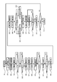
Images


Classifications
-
- B—PERFORMING OPERATIONS; TRANSPORTING
- B42—BOOKBINDING; ALBUMS; FILES; SPECIAL PRINTED MATTER
- B42B—PERMANENTLY ATTACHING TOGETHER SHEETS, QUIRES OR SIGNATURES OR PERMANENTLY ATTACHING OBJECTS THERETO
- B42B4/00—Permanently attaching together sheets, quires or signatures by discontinuous stitching with filamentary material, e.g. wire
-
- B—PERFORMING OPERATIONS; TRANSPORTING
- B42—BOOKBINDING; ALBUMS; FILES; SPECIAL PRINTED MATTER
- B42C—BOOKBINDING
- B42C1/00—Collating or gathering sheets combined with processes for permanently attaching together sheets or signatures or for interposing inserts
- B42C1/12—Machines for both collating or gathering and permanently attaching together the sheets or signatures
-
- G—PHYSICS
- G03—PHOTOGRAPHY; CINEMATOGRAPHY; ANALOGOUS TECHNIQUES USING WAVES OTHER THAN OPTICAL WAVES; ELECTROGRAPHY; HOLOGRAPHY
- G03G—ELECTROGRAPHY; ELECTROPHOTOGRAPHY; MAGNETOGRAPHY
- G03G15/00—Apparatus for electrographic processes using a charge pattern
- G03G15/65—Apparatus which relate to the handling of copy material
- G03G15/6538—Devices for collating sheet copy material, e.g. sorters, control, copies in staples form
- G03G15/6541—Binding sets of sheets, e.g. by stapling, glueing
- G03G15/6544—Details about the binding means or procedure
-
- B—PERFORMING OPERATIONS; TRANSPORTING
- B65—CONVEYING; PACKING; STORING; HANDLING THIN OR FILAMENTARY MATERIAL
- B65H—HANDLING THIN OR FILAMENTARY MATERIAL, e.g. SHEETS, WEBS, CABLES
- B65H2701/00—Handled material; Storage means
- B65H2701/10—Handled articles or webs
- B65H2701/13—Parts concerned of the handled material
- B65H2701/132—Side portions
- B65H2701/1321—Side portions of folded article or web
- B65H2701/13212—Fold, spine portion of folded article
-
- G—PHYSICS
- G03—PHOTOGRAPHY; CINEMATOGRAPHY; ANALOGOUS TECHNIQUES USING WAVES OTHER THAN OPTICAL WAVES; ELECTROGRAPHY; HOLOGRAPHY
- G03G—ELECTROGRAPHY; ELECTROPHOTOGRAPHY; MAGNETOGRAPHY
- G03G2215/00—Apparatus for electrophotographic processes
- G03G2215/00362—Apparatus for electrophotographic processes relating to the copy medium handling
- G03G2215/00919—Special copy medium handling apparatus
- G03G2215/00936—Bookbinding
Description
本発明は、折り畳まれたシートで形成される冊子の折り頂部を処理するシート処理装置及び画像形成システムに関するものである。 The present invention relates to a sheet processing apparatus and an image forming system for processing a folded top portion of a booklet formed of folded sheets.
概略20枚以上のシートを一括に折り畳むと、折り頂部近傍が湾曲した冊子が仕上がることがある。こうした冊子は、折りが不十分であり、折り畳まれても直ぐに開いてしまい、見栄えの良くない外観を呈する。この様な冊子は、平坦な状態で載置することができないため、多数部積み重ねることが困難となっていた。こうした課題に対応すべく、変形処理の一つとして冊子の折り頂部を四角く角付け処理する特許文献1に記載のシート処理装置が開示されている。
When approximately 20 or more sheets are folded together, a booklet with the vicinity of the folding top curved may be finished. These booklets are not fully folded and open immediately when folded, giving them an unsightly appearance. Since such a booklet cannot be placed in a flat state, it has been difficult to stack many copies. In order to cope with such a problem, a sheet processing apparatus described in
特許文献1に記載の発明は、冊子を折り曲げた状態で把持して固定するクランピングジョー、クランピングジョーから突出する冊子の長さを規制可能な停止板、冊子の背部をプレス成形する圧接ローラ、を備えるシート処理装置に関するものである。こうしたシート処理装置によれば、冊子の背部が角付けされ、冊子の背部の平坦化が実現される。そうした意味では、前述の見栄えの良くない外観が修正され、また、多数の冊子を積み重ねた際にも冊子の姿勢は安定する。
The invention described in
しかしながら、特許文献1に記載の発明では、クランピングジョーから突出する冊子の折り頂部を圧接する構成となっているので、その変形量が大きいと角付け処理された折り頂部が冊子の厚さ方向に広がってしまい、見栄えが低下することがあった。所定量突出した折り頂部に対して所定の圧接力を加えたとき、冊子の厚さが薄い場合には、折り頂部の変形量が過多となり、逆に冊子の厚さが厚い場合には、折り頂部に対する圧接力が不足して変形不十分となるおそれがある。
However, in the invention described in
本発明は、上記実情に鑑み、薄い冊子の折り頂部の過度の変形や厚い冊子の折り頂部の変形不足を回避し、変形処理(角付け処理)された冊子の形状の安定化を図ることができるシート処理装置を提供することを課題とする。 In view of the above circumstances, the present invention avoids excessive deformation of a folded portion of a thin booklet or insufficient deformation of a folded portion of a thick booklet, and stabilizes the shape of a deformed (squared) booklet. It is an object of the present invention to provide a sheet processing apparatus that can be used.
上記課題を解決するために、本発明のシート処理装置は、折り畳まれたシートで形成される冊子を対向する保持部材対で保持する保持手段と、前記保持手段により保持された冊子の折り頂部に圧接する第1の圧接部材と、前記第1の圧接部材よりも冊子の厚さ方向の厚さの厚い第2の圧接部材と、を有する圧接手段と、前記圧接部材を前記折り頂部に沿って移動させる移動手段と、を備え、前記第1の圧接部材と前記第2の圧接部材の一方は、選択的に前記保持部材対の間に進入して前記保持部材対により保持された冊子の折り頂部に圧接して前記折り頂部に沿って移動しながら前記折り頂部を変形処理し、所定の厚さよりも厚い冊子を変形処理する場合、前記折り頂部を圧接するために前記第2の圧接部材が選択され、前記第2の圧接部材による前記折り頂部を圧接する圧接方向の押し込み量は前記第1の圧接部材によるものよりも大きいことを特徴とする。 In order to solve the above problems, a sheet processing apparatus according to the present invention includes a holding unit that holds a booklet formed by a folded sheet with a pair of holding members facing each other, and a folding top portion of the booklet held by the holding unit. A pressure contact means having a first pressure contact member that is in pressure contact, and a second pressure contact member that is thicker in the thickness direction of the booklet than the first pressure contact member; and the pressure contact member along the folding top portion. and a moving means for moving the said one of the first pressing member and said second pressing member, of the booklet held by the holding member pair enters between the holding member pair selectively When the folding top portion is deformed while moving along the folding top portion while being pressed against the folding top portion, and the booklet having a thickness greater than a predetermined thickness is deformed, the second pressure contacting member is used to press the folding top portion. And the second pressure contact member The push-in amount of the press-contact direction for pressing the top fold due to being greater than that by the first pressing member.
本発明によれば、冊子の折り頂部を圧接部材で圧接して変形(角付け)処理する際、薄い冊子には押し込み量(圧接量)が小さくなるよう、厚い冊子には押し込み量(圧接量)が大きくなるように冊子の厚さに応じて押し込み量(圧接量)を変更する。これにより、薄い冊子の過度の変形や厚い冊子の変形不足を回避し、変形(角付け)処理された冊子の形状の安定化を図ることができる。 According to the present invention, when processing deformed pressed against the spine of the booklet in pressure contact member (squaring) the amount of push the thin booklet to (amount pressure) becomes smaller, the thicker booklet push amount (pressure amount ) to change the pushing amount (weight pressure) in accordance with the thickness of the booklet to increase. Thereby, it is possible to avoid excessive deformation of the thin booklet and insufficient deformation of the thick booklet, and to stabilize the shape of the deformed (squared) booklet.
以下、本発明の好適な実施の形態を例示的に詳しく説明する。ただし、この実施の形態に記載される構成部品の寸法、材質、形状、それらの相対位置等は、本発明が適用される機構の構成や各種条件により適宜変更されるから、特に特定的な記載が無い限りは、本発明の範囲をそれらのみに限定する趣旨のものではない。 Hereinafter, exemplary embodiments of the present invention will be described in detail by way of example. However, since the dimensions, materials, shapes, relative positions, and the like of the components described in this embodiment are appropriately changed depending on the configuration of the mechanism to which the present invention is applied and various conditions, particularly specific descriptions are provided. Unless otherwise, the scope of the present invention is not limited to these.
[第1実施形態]
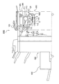
図1は、本発明の実施の形態に係るシート処理装置と画像形成装置本体を備えた画像形成システムの構成を示す断面図である。図1に示されるように、本実施の形態に係る画像形成システムである複写装置1000は、プリンタ部300と、フィニッシャ500、中綴じ製本部800(図2参照)、角付け処理装置600等を有する。なお、画像形成装置本体は、原稿シート給送部100、イメージリーダ部200及びプリンタ部300を含んで、プリンタ部300は、シートに画像を形成する画像形成部を備える。
[First Embodiment]
FIG. 1 is a cross-sectional view illustrating a configuration of an image forming system including a sheet processing apparatus and an image forming apparatus main body according to an embodiment of the present invention. As shown in FIG. 1, a
プリンタ部300は、感光体ドラム111、露光制御部110、現像器113、転写器116を備える。露光制御部110は、イメージセンサ109により読み取られた原稿シートの画像データに所定の画像処理が施されたものを受信する。露光制御部110は、画像信号に応じたレーザ光を出力する。レーザ光は、ポリゴンミラー110aにより走査されながら感光体ドラム111の表面に照射される。感光体ドラム111の表面には、走査されたレーザ光に応じた静電潜像が形成される。前述の感光体ドラム111、露光制御部110、現像器113、転写器116を含んで画像形成部1003が構成される。
The
感光体ドラム111の表面に形成された静電潜像は、現像器113により現像され、トナー像として可視化される。一方、シートは、給紙部1002を構成するカセット114、115、手差し給送部125、両面搬送パス124の何れかから転写器116へ搬送される。そして、可視化されたトナー像が転写器116においてシートに転写される。転写後のシートには、定着器117にて定着処理が施される。
The electrostatic latent image formed on the surface of the
シートは、定着器117を通過した後にフラッパ121により一旦パス122に導かれる。シートの後端がフラッパ121を抜けると、シートはスイッチバックされ、フラッパ121により排出ローラ118へと搬送される。シートは排出ローラ118によりプリンタ部300から排出される。これにより、トナー像が形成された面が下向きに向けられた状態(フェイスダウン)でシートがプリンタ部300から排出される。シートが紙の場合には、この現象は反転排紙と称される。なお、シートの両面印刷の場合には、シートの後端がフラッパ121を抜けると、シートがスイッチバックされ、フラッパ121により両面搬送パス124へと導かれる。
The sheet passes through the
図2は、フィニッシャ500及び角付け処理装置600の構成を示す断面図である。図2に示されるフィニッシャ500は、シートを複数取り込んで整合し、1つのシート束として束ねる束ね処理、シート束の後端側をステイプルするステイプル処理(綴じ処理)、ソート処理、ノンソート処理等するための装置である。フィニッシャ500は、搬送されたシートを内部に取り込むための搬送パス520を備える。搬送パス520には、複数の搬送ローラ対が設けられている。搬送パス520の途中には穴開け処理部であるパンチユニット530が設けられる。パンチユニット530は必要に応じて駆動し、搬送されるシートの後端部に穴開け(穿孔)処理を行う。
FIG. 2 is a cross-sectional view showing the configuration of the
次に、中綴じ製本部800の構成を説明する。下搬送パス522の途中には切替フラッパ514が配置される。この切替フラッパ514によって切り替えられたシートは、サドル排出パス523を通過して、中綴じ製本部800へ送られる。シートはサドル入口ローラ対801に受け渡され、サイズに応じてソレノイドにより動作するフラッパ802により搬入口を選択されて、中綴じ製本部800の収納ガイド803の内部に搬入される。シートは、滑りローラ804により先端が可動式のシート位置決め部材805に接するまで搬送される。サドル入口ローラ対801及び滑りローラ804はモータM1により駆動される。また、収納ガイド803の途中位置には、収納ガイド803を挟んで対向配置されたステイプラ820が設けられている。ステイプラ820は、針を突き出すドライバー820a及び突き出された針を折り曲げるアンビル820bに分割されている。なお、シート位置決め部材805は、シートが搬入されるときに、シート搬送方向Xの中央部が、このステイプラ820の綴じ位置になる位置で停止する。シート位置決め部材805は、モータM2の駆動を受けて移動自在であり、シートサイズに応じて位置を変える。
Next, the configuration of the saddle
ステイプラ820の下流側には、折りローラ対810a、810bが設けられており、折りローラ対810a、810bの対向位置には、折りローラ対810a、810bとともに折り部を構成する突き出し部材830が設けられている。この突き出し部材830は、収納ガイド803から退避した位置をホームポジションとしていて、モータM3の駆動により収納されたシート束に向けて突き出すと、シート束を、折りローラ対810a、810bのニップに押し込みながら折り畳むのである。突き出し部材830はその後、再びホームポジションに戻る。なお、折りローラ対810a、810b間には、シート束に折り目付けをするのに充分な圧F1が不図示のバネにより掛けられている。折り目付けされたシート束は、第1折り搬送ローラ対811a、811b、第2折り搬送ローラ対812a、812bを介して、角付け処理装置600(図1参照)に搬送される。第1折り搬送ローラ対811a、811b及び第2折り搬送ローラ対812a、812bにも、折り目付けされたシート束を搬送及び停止させるのに充分な圧F2、F3が掛けられている。
A pair of
折りローラ対810a、810b、第1折り搬送ローラ対811a、811b、第2折り搬送ローラ対812a、812bは、同一のモータM4(不図示)により等速回転する。また、ステイプラ820で綴じられたシート束を折り畳む場合は、ステイプル処理終了後に、シート束のステイプル位置が折りローラ対810a、810bのニップ位置にくるように、シート位置決め部材805を、ステイプル処理時の場所から所定距離で降下させる。これによりステイプル処理を施した位置を中心にしてシート束を折りたたむことができる。また、整合板対815は折りローラ対810a、810bの外周面を周りながら収納ガイド803に突き出した面を持ち、収納ガイド803に収納されたシートを整合する整合板対である。整合板対815は、モータM5の駆動を受けて、シートに対し、挟みこみ方向に移動することで、シート幅方向で位置決めする。
The pair of
図3は、角付け処理装置600で角付け処理された冊子Kの構成を示す斜視図である。
FIG. 3 is a perspective view showing the configuration of the booklet K that has been subjected to the squaring process by the squaring
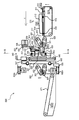
図4は、角付け処理装置600の構成を示す拡大断面図である。角付け処理装置600は、中綴じ製本部800(図2参照)よりもシート搬送方向Xの下流側に配置される。図4に示されるように、角付け処理装置600は冊子受け取り部610を備える。冊子受け取り部610は、中綴じ製本部800から冊子Sを受け取って搬送するために、シート搬送方向Xに伸びる下搬送ベルト611を備える。冊子Sの受け渡し時には下搬送ベルト611は矢印の方向に回転している。したがって、第2折り搬送ローラ対812a、812bから冊子Sが落下すると、冊子Sは、転がることなく搬送されてきた姿勢のまま受け取られる。
FIG. 4 is an enlarged cross-sectional view showing the configuration of the squaring
下搬送ベルト611を挟むようにした下搬送ベルト611の外側にはサイドガイド対612が配設される。サイドガイド対612がシート搬送方向Xと直交するシート幅方向Yに動作することで、冊子Sのシート幅方向Yの位置は修正される。また、サイドガイド対612の上側には、冊子Sの開きを防止する押えガイド614が形成されている。この押えガイド614は、シート搬送方向Xの下流部へスムーズに冊子Sを受け渡すためのガイドとして機能する。さらに、下搬送ベルト611を挟んだ両側には、下搬送ベルト611と平行に移動する搬送爪613が配設されている。搬送爪613は、下搬送ベルト611と略同じ速度で正方向移動及び逆方向移動する。下搬送ベルト611と冊子Sとの間にすべりが生じた場合は、この搬送爪613が冊子Sの後端と接触し、確実に冊子Sの後端をシート搬送方向Xの下流側へと押し込む。なお、下搬送ベルト611、サイドガイド対612、搬送爪613は、それぞれ駆動モータSM1、SM2、SM3の駆動を受けて動作する。入口検知センサ615は、中綴じ製本部800から受け取られた冊子Sが下搬送ベルト611の上にあるか否かを検知する。出口検知センサ616は、冊子Sを検知することによりサイドガイド対612、搬送爪613を動作させるための入力信号を発信可能である。
A pair of side guides 612 is disposed outside the
搬送部620は、冊子受け取り部610から冊子Sを受け取ってシート搬送方向Xの下流へと冊子Sを搬送する下搬送ベルト621及び上搬送ベルト622を備える。上搬送ベルト622は、支点623を中心に冊子Sの厚さによって回動できるようになっており、下搬送ベルト621へ不図示のバネにより押圧されている。上搬送ベルト622及び下搬送ベルト621は駆動モータSM4によって駆動する。
The
角付け処理装置600は、冊子Sの折り頂部Tの近傍を上下から押さえつける保持手段である保持ユニット630、及び、冊子Sの折り頂部Tを位置決めしてかつ冊子Sの折り頂部Tを圧接する圧接手段である角付けユニット640で構成されている。
The squaring
保持手段としての保持ユニット630は、第1保持部材である下側保持板631及び第2保持部材である上側保持板633を備える。下側保持板631は、冊子Sを下側から保持する第1保持面である下保持面631a(図7参照)を有し、上側保持板633は、冊子Sを上側から保持する第2保持面である上保持面633a(図7参照)を有する。保持ユニット630は、折り畳まれたシートで形成される冊子Sを対向する下保持面631a及び上保持面633aで保持する。下側保持板631は固定されるが、上側保持板633は昇降可能に構成されている。
The holding
保持ユニット630の上部は、駆動モータSM5の駆動でリンク636、637、638を介して昇降する強固な保持ベース632、スライド連結部材634で連結された上側保持板633、及びスライド連結部材634の外周に配置される圧縮バネ635を備える。保持ベース632が上位置にあるときに、下側保持板631及び上側保持板633は離間しており、その間に冊子Sが搬送される。また、保持ベース632が下位置にあるときには、冊子Sの厚さに応じて伸縮する圧縮バネ635によって、冊子Sは下側保持板631及び上側保持板633で確実に挟圧保持される。下側保持板631及び上側保持板633が冊子Sを保持する下保持面631a及び上保持面633aは、突起のない平滑面である。そのために、冊子Sを挟圧保持したときに冊子Sに圧接痕をつけるようなことは抑制される。上死点検知センサ639は、保持ベース632が上位置にあることを検知するセンサである。厚さ検知センサ681は、冊子Sを固定したときの上側保持板633の位置を検知して冊子Sの厚さを検知するセンサである。
The upper part of the holding
角付けユニット640は、第1、第2の圧接部材である第1圧接片650及び第2圧接片651、切替手段である切替ベース644及びスライドネジ645、を備える。また、角付けユニット640は、移動手段であるタイミングベルト652a、652b、位置決め手段であるストッパ片649(図5の649a、649bを参照)を備える。第1圧接片650及び第2圧接片651は、それぞれ圧接位置650p、651p(図7参照)において折り頂部Tに圧接して変形処理し、支持軸648a、648bに対して同軸上に設けられる。第1圧接片650及び第2圧接片651は、互いに対向する下保持面631a及び上保持面633aで保持される冊子Sの折り頂部Tに対し、保持部材対間即ち下側保持板631及び上側保持板633の間(図7参照)に進入して圧接する。圧接にあたって、第2圧接片651及び第1圧接片650は、支持軸648aの回転により回転する回転部材である。複数すなわち2つの第2圧接片651及び第1圧接片650は、冊子Sの厚さ方向の厚さ(高さ)及び外径が異なる構成である。従って、第1圧接片650及び第2圧接片651の厚さは異なり、変形前の冊子Sの折り頂部Tから第1圧接片650の第1圧接位置650p及び第2圧接片651の第2圧接位置651pまでの圧接方向の変形量が異なる。詳しくは後述するが、第1圧接片650及び第2圧接片651の圧接方向の変形量は、保持される冊子Sの厚さが厚い程大きい。なお、ストッパ片649a、649bの冊子Sの厚さ方向の厚さ(高さ)及び外径も第1圧接片650及び第2圧接片651と異なる。
The squaring
切替手段である切替ベース644及びスライドネジ645は、第1圧接片650及び第2圧接片651、及び、ストッパ片649a、649bを選択的に切り替え可能に構成されている。移動手段であるタイミングベルト652a、652bは、選択された第1圧接片650及び第2圧接片651を折り頂部Tに沿って移動させる。角付けユニット640は、冊子Sの厚さに基づいて第1圧接片650及び第2圧接片651のうち下側保持板631と上側保持板633の間に進入可能で、冊子Sの厚さに対応する厚さの方を選択して折り頂部Tに沿って圧接させつつ移動させるようになっている。
The switching
位置決め手段であるストッパ片649a、649bは、搬送される冊子Sの折り頂部Tをシート搬送方向Xの所定位置(受け止め位置649p)に位置決めする。前述の選択された第1圧接片650及び第2圧接片651は、ストッパ片649a、649bにより折り頂部Tが受け止め位置649pに位置決めされた冊子Sに接する。詳しくは後述するが、ストッパ片649a、649bは、搬送されてくる冊子Sの折り頂部Tを受け止め位置649pで受け止める受け止め部材として機能する。
図5は、図4のQ−Q線に沿う方向から見た角付けユニット640の主要部材の構成を示す概略図である。図5に示されるように、角付けユニット640は、移動ユニット656a及び移動ユニット656bといった2つの移動ユニットを備える。これらの移動ユニット656a、656bは、不図示の枠体に支持される図4に示されるスライド軸642、643に沿って移動可能となっており、図5に示されるように、矢印Aの方向に移動可能に支持される。この矢印Aの方向の移動のために、移動ユニット656a、656bは、連結部材653aによってタイミングベルト652aに取り付けられる。また、タイミングベルト652aは、プーリ654a、655aを介して駆動モータSM6によって駆動される。
FIG. 5 is a schematic diagram showing the configuration of the main members of the squaring
図6は、図4のR−R線に沿う方向から見た角付けユニット640の主要部材の構成を示す概略図である。図6に示されるように、前述したと同様に、角付けユニット640は、移動ユニット656a及び移動ユニット656bといった2つの移動ユニットを備える。また、図6に示されるように、角付けユニット640は、不図示の枠体に支持されて水平方向に延びるスライド軸642、643を備える。移動ユニット656a及び移動ユニット656bは、矢印Aの方向に移動可能に支持されている。
FIG. 6 is a schematic diagram showing the configuration of the main members of the squaring
移動ユニット656aは移動ベース641aを備え、移動ユニット656bは移動ベース641bを備える。移動ベース641aにはスライド軸646、647が上下方向に延びるように固定される。このスライド軸646、647に沿って切替ユニット657がスライド可能に支持されている。切替ユニット657は、スライド軸646、647と平行に配置されるスライドネジ645、及び、スライドネジ645を回転させる駆動モータSM8の駆動によって、スライドネジ645に沿って矢印Bで示す上下方向へと移動可能に構成されている。
The moving
切替ユニット657は切替ベース644を備える。切替ベース644には支持軸648aが回転自在に取り付けられている。支持軸648aには、前述したように位置決め手段であるストッパ片649a、649b、圧接部材である第1圧接片650、第2圧接片651が固定されている。
The
ストッパ片649aは、前述したストッパ片649bと協同して、搬送されてくる冊子Sの折り頂部Tが突き当たることで、冊子Sを変形(角付け)処理する位置に冊子Sを位置決めする部材である。第1圧接片650、第2圧接片651は冊子Sの折り頂部Tを圧接して変形(角付け)処理する部材であり、冊子Sの厚さに応じて切替ユニット657を図6の矢印Bの方向に移動することで切り替える。切替ユニット657には基準位置検知センサ659があり、矢印Bの方向に移動するときの基準位置となっている。
The
移動ユニット656bは、連結部材653bによってタイミングベルト652bに取り付けられ、プーリ654b、655bを介して駆動モータSM7によって駆動される。移動ユニット656bは、移動ベース641bを有する。移動ベース641bには、支持軸648bが回転自在に取り付けられている。支持軸648bにはストッパ片649bが固定されている。ストッパ片649bはストッパ片649aと協同し、搬送されてくる冊子Sの折り頂部Tが突き当たることで角付け処理する位置に位置決めする部材である。なお、移動ユニット656a、移動ユニット656bには、それぞれ、基準位置検知センサ658a、658bがあり、矢印A方向に移動するときの基準位置となっている。
The moving
上述したような構成であるために、ストッパ片649a、649b、第1圧接片650、第2圧接片651は、冊子Sの折り頂部Tと平行なシート幅方向Yに移動可能であるが、冊子Sの折り頂部Tと直交するシート搬送方向Xには移動できない(図7参照)。なお、ストッパ片649aは昇降可能であるが、ストッパ片649bは昇降しないように構成されている。
The
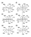
図7は、冊子Sの折り頂部Tがストッパ片649a、649bに当接する当接状態、及び第1圧接片650、第2圧接片651に圧接された圧接状態を示す断面図である。図7に示されるストッパ片649a、649b、第1圧接片650、第2圧接片651は、いずれも円盤状に形成される。このストッパ片649a、649b、第1圧接片650、第2圧接片651の厚さ及び外径に関しては、以下に詳述する。
FIG. 7 is a cross-sectional view illustrating a contact state in which the folded top portion T of the booklet S contacts the
保持部材である下側保持板631及び上側保持板633は、前述したようにそれぞれ下保持面631a及び上保持面633aを有する。下保持面631a及び上保持面633aと直交する方向(支持軸648a、648bの方向)から見て、下保持面631a及び上保持面633aは、冊子Sの折り頂部Tの領域を全て含んで冊子Sを保持する。これに関しても、以下に詳述する。
As described above, the
図7(a)及び図7(b)に示されるように、ストッパ片649a、649bの直径はD1で形成される。冊子Sは下側保持板631及び上側保持板633の間に入り込む。そして、冊子Sは、下側保持板631及び上側保持板633の間で下側保持板631及び上側保持板633のシート搬送方向Xの下流側から突出しない位置で位置決めされるようになっている。予め、ストッパ片649a及びストッパ片649bの冊子Sの厚さ方向の厚さ(高さ)はH1に設定され、搬送されてくる冊子Sの厚さよりも厚く(高く)設定されている。これは、冊子Sが厚い場合であっても、冊子Sの折り頂部Tがストッパ片649a及びストッパ片649bを乗り越えるのを防止するためである。
As shown in FIGS. 7A and 7B, the
本実施の形態における中綴じ製本部800で作成される冊子Sとしては、シートの1枚を二つ折りした冊子からシート25枚を二つ折りした冊子を想定している。そのうち、1枚から10枚までのシートを二つ折りした冊子Sは角付け処理せず、11枚から25枚までのシートを二つ折りした冊子Sを角付け処理するように設定している。
As the booklet S created by the saddle
これは、1枚から10枚までのシートを二つ折りした冊子は厚さが薄く、折り頂部Tの湾曲部が小さいため、変形処理としての角付け処理する変形量(押し込み量)を確保しにくい、十分な折りであるため角付け処理しても冊子の開き易さが変わらないことによる。11枚から25枚までのシートを二つ折りした冊子は角付け処理される。そして、シート11枚から25枚を二つ折りした冊子は厚さが厚いことに加えて厚さ領域の幅が大きいために、冊子の厚さを二段階に分ける。そして、図7(c)、(d)、(e)、(f)のように冊子Sの厚さがT2からT3のときは厚さH2の第1圧接片650に、冊子Sの厚さがT3(所定の厚さ)を超えるT4からT5のときは厚さH3の第2圧接片651に切り替えてシート処理を行うようになっている。
This is because a booklet obtained by folding one to ten sheets in half is thin and the bending portion of the folding top portion T is small, so that it is difficult to secure a deformation amount ( push-in amount) for the squaring process as the deformation processing. Because the folding is sufficient, the ease of opening the booklet does not change even when the squaring process is performed. A booklet in which 11 to 25 sheets are folded in half is squared. And since the booklet which folded the sheet | seat from 11 sheets into 25 sheets is thick in addition to the thickness being thick, the thickness of the booklet is divided into two stages. When the thickness of the booklet S is from T2 to T3 as shown in FIGS. 7C, 7D, 7E and 7F, the thickness of the booklet S is applied to the first
また、ストッパ片649a、649bの直径D1、第1圧接片650の直径D2、第2圧接片651の直径D3は、D1<D2<D3という関係になっている。比較的薄めの冊子Sを角付け処理するのに使用する第1圧接片650のときは、折り頂部Tの湾曲部の大きさに対応する変形量(押し込み量)P2=(D2−D1)/2である。このP2は第1圧接片650の折り頂部Tに対する進入量とも言える。厚い冊子Sを角付け処理するのに使用する第2圧接片651のときは、折り頂部Tの湾曲部の大きさに対応する変形量(押し込み量)P3=(D3−D1)/2である。このP3は第2圧接片651の折り頂部Tに対する進入量とも言える。薄めの冊子Sに比べて厚い冊子Sの変形量(押し込み量)が大きくなるよう(P2<P3)に設定している。
The diameter D1 of the
本実施の形態において、上下保持板631、633の保持面は、冊子の折り頂部が圧接される前には冊子の折り頂部と当接しない。そして、圧接片による冊子の折り頂部の圧接が開始されると、上下保持板631、633の保持面と当接していない冊子の折り頂部が変形し始める。しかしながら、上下保持板631、633の保持面によって保持面間隔、すなわち上下保持板631、633によって保持された冊子の厚さを超えるような変形が規制される。このとき、上下保持板631、633の保持面は、折り頂部の、冊子の厚さ方向の変形を規制する規制面として機能する。このように保持面間隔内で変形処理されることで折り頂部の厚さ方向の変形が制限され、積載性が向上する。
In this embodiment, the holding surface of the top and
本実施の形態において、上下保持板631、633の押さえ面は、互いに平行な上下保持板631、633の保持面と連続する平滑面として設定されているが、冊子の厚さを超えるような変形を押さえられればよく、必ずしも平行でなくてもよい。また、押さえ面は上下保持板631、633の保持面と連続している必要はなく、別部材で設けてもよい。
In the present embodiment, the pressing surfaces of the upper and
本実施の形態において、変形処理としての角付け処理する変形量(押し込み量)は、ストッパ片649a、649bによる位置決め位置ではなく、第1圧接片650及び第2圧接片651の直径の大きさで設定している。上述のように、薄い冊子Sでも厚い冊子Sでも同じストッパ片649a、649bで位置決めするので、冊子の厚さにかかわらず同じ位置に位置決めすることができる。そして、本実施の形態において、冊子Sの厚さが薄い角付け処理に使用する圧接片の厚さが薄くて直径が小さく、冊子Sの厚さが厚いと角付け処理に使用する圧接片の厚さが厚くて直径が大きくなっている。これは、冊子Sの厚さによらず位置決めする位置を同じにして、薄い冊子Sに比べて厚い冊子Sの押し込み量が常に大きくなるように設定し、また、薄い冊子Sの過度の変形や厚い冊子Sの変形不足を回避し、角付け処理された冊子Sの形状を安定化するためである。
In the present embodiment, the deformation amount ( push-in amount) to be squared as the deformation processing is not the positioning position by the
なお、本実施の形態では、冊子Sの厚さを2つに場合わけし、互いに厚さ及び外径が異なる2種類の第1圧接片650及び第2圧接片651が使用される場合を例示したが、上記実施の形態に限定されない。すなわち、互いに厚さ及び外径が異なる3種類又は4種類又はそれ以上の種類の圧接片が用いられても良い。
In the present embodiment, the thickness of the booklet S is divided into two, and the case where two types of first
また、同じ厚さの冊子Sでも、使用するメディアによって冊子Sの剛度(変形し易さ)が異なることがある。こういった場合には、圧接片の形状は円盤状に限定されない。すなわち、圧接片の折り頂部を圧接する圧接面の中央が凸状に形成されるなど圧接面の形状が変更されても良い。また、圧接面の形状が異なる圧接片を複数用意しておいて、使用しているメディアによって複数の圧接片が切り替えられても良い。 Further, even for a booklet S having the same thickness, the stiffness (ease of deformation) of the booklet S may differ depending on the media used. In such a case, the shape of the pressure contact piece is not limited to a disk shape. That is, the shape of the pressure contact surface may be changed, for example, the center of the pressure contact surface that presses the folded top portion of the pressure contact piece is formed in a convex shape. Alternatively, a plurality of press contact pieces having different press contact surface shapes may be prepared, and the plurality of press contact pieces may be switched depending on the medium being used.
図8、図9、図10は、角付けユニット640の動作を示す工程図である。図5で前述したが、移動ユニット656a、656bがスライドすることにより、ストッパ片649a、649b、第1圧接片650、第2圧接片651は、保持ユニット630の下側保持板631及び上側保持板633の間を矢印Aの方向に移動可能である。そして、移動ユニット656aが下側保持板631及び上側保持板633の間から外れた位置に配置されたときに、図6に示される切替ユニット657がスライドネジ645に沿ってスライドする。そして、図7に示されるように、下側保持板631及び上側保持板633の間に配置されるべき第1圧接片650と第2圧接片651が切り替えられる。移動ユニット656aが外れた位置に配置されるとは、下側保持板631及び上側保持板633の脇に配置されることをいう(図8(a)参照)。
8, 9, and 10 are process diagrams illustrating the operation of the squaring
図8(a)に示されるように、冊子Sが保持ユニット630で位置決めされるときには、ストッパ片649a、649bは、下側保持板631及び上側保持板633の間で、シート幅方向Yの中心を対称として冊子Sの幅寸法よりも内側に配置される。これにより、冊子Sの折り頂部Tがストッパ片649a、649bに突き当てられて、冊子Sは位置決めされる。冊子Sがストッパ片649a、649bまで搬送されたことは、位置決め検知センサ626により検知される。また、ストッパ片649a、649bの厚さ寸法は、厚い冊子Sの折り頂部Tが突き当たって位置決めできるように、冊子Sの厚さよりも厚く設定されている(図7(a)(b)参照)。下側保持板631及び上側保持板633の間にストッパ片649a、649bが位置するときは、上側保持板633は冊子Sを保持できないようになっている。このことから、ストッパ片649a、649bは、冊子Sを位置決めする機能のみを有し、冊子Sに対して圧接する機能を有しない(図7(a)(b)参照)。
As shown in FIG. 8A, when the booklet S is positioned by the holding
図8(b)に示されるように、冊子Sが位置決めされた後には、ストッパ片649a、649bは、下側保持板631及び上側保持板633の脇に配置される。そして、冊子Sの折り頂部T及びその近傍は、保持ユニット630の下側保持板631及び上側保持板633の間で押圧保持される。このときに、冊子Sの折り頂部Tは、下側保持板631及び上側保持板633のシート搬送方向Xの下流側の端面から突出しない。なお、このときに、冊子Sは、搬送部620の下搬送ベルト621及び上搬送ベルト622により挟持されているので、ずれることはない。
As illustrated in FIG. 8B, after the booklet S is positioned, the
図9(a)に示されるように、厚さ検知センサ681(図4参照)が検知する冊子Sの厚さに基づいて切替ユニット657(図6参照)が駆動して、ストッパ片649aは、第1圧接片650、第2圧接片651に切り替えられる。図9(a)は、第2圧接片651に切り替えられた状態を示している。
As shown in FIG. 9A, the switching unit 657 (see FIG. 6) is driven based on the thickness of the booklet S detected by the thickness detection sensor 681 (see FIG. 4), and the
図9(b)に示されるように、移動ユニット656aが冊子Sの一方の角部から他方の角部の方に向かって移動される。これにより、第2圧接片651が冊子Sの折り頂部Tに圧接され、冊子Sの背部は角付け処理されるようになっている。図10(a)に示されるように、移動ユニット656aが冊子Sの他方の角部を越えて移動されて移動ユニット656bの近傍まで到達すると、移動ユニット656aは停止される。図10(b)に示されるように、角付け処理された冊子Sは、シート搬送方向Xの下流側へと搬送される。折り頂部Tが角付け処理された冊子Kは、前述した図3に示されるようになる。
As shown in FIG. 9B, the moving
図4に示されるように、角付けユニット640は搬送部660を備える。搬送部660は下搬送ベルト661及び上搬送ベルト662を備える。冊子Sは角付け処理されて冊子Kとなり、冊子Kでは保持ユニット630の押圧保持が解除され、下搬送ベルト661及び上搬送ベルト662によってシート搬送方向Xの下流側へと搬送される。上搬送ベルト662は支点663を中心に冊子Kの厚さによって回動できるようになっており、下搬送ベルト661へ不図示のバネにより押圧されている。下搬送ベルト661及び上搬送ベルト662は搬送部620と駆動連結されており、駆動モータSM4によって駆動するようになっている。
As shown in FIG. 4, the squaring
また、図4に示されるように、角付け処理装置600は、搬送部660から排出された冊子Kが積載されるコンベアベルト671を備える。コンベアベルト671は、駆動モータSM10の駆動力に基づいて、冊子Kが排出される度に所定量の移動を繰り返して冊子Kをシート搬送方向Xに搬送し、シート搬送方向Xの下流側で冊子Kを積載する。なお、冊子Kが搬送部660から排出されたことは、排出検知センサ664により検知される。
Further, as shown in FIG. 4, the squaring
図11は、複写装置1000のブロック図である。図11に示されるように、複写装置1000の内部のCPU回路部150は、CPU(不図示)を有し、ROM151に格納された制御プログラム及び操作部1の設定に従って各制御部を制御する。すなわち、CPU回路部150は、原稿給送制御部101、イメージリーダ制御部201、画像信号制御部202、プリンタ制御部301、フィニッシャ制御部501、外部I/F203を制御する。そして、原稿給送制御部101は原稿シート給送部100を、イメージリーダ制御部201はイメージリーダ部200を、プリンタ制御部301はプリンタ部300を制御する。また、フィニッシャ制御部501はフィニッシャ500、中綴じ製本部800を、角付け処理制御部601はフィニッシャ制御部501からの指令に基づき角付け処理装置600を制御する。
FIG. 11 is a block diagram of the
操作部1は、画像形成に関する各種機能を設定するための複数のキー、設定状態を表示するための表示部等を有する。操作部1は、ユーザによる各キーの操作に対応するキー信号をCPU回路部150に出力すると共に、CPU回路部150からの信号に基づき対応する情報を表示部に表示する。
The
RAM152は、制御データを一時的に保持するための領域や、制御に伴う演算の作業領域として用いられる。外部I/F203は、複写装置1000と外部のコンピュータ204とのインタフェースであり、コンピュータ204からのプリントデータをビットマップ画像に展開し、画像データとして画像信号制御部202へ出力する。また、イメージリーダ制御部201から画像信号制御部202へは、イメージセンサ(不図示)で読み取った原稿シートの画像が出力される。プリンタ制御部301は、画像信号制御部202からの画像データを露光制御部(不図示)へ出力する。
The
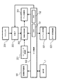
図12は、角付け処理制御部601のブロック図である。図12に示されるように、角付け処理制御部601は各駆動モータを制御するようになっている。すなわち、角付け処理制御部601は、冊子受け取り部610の下搬送ベルト611用の駆動モータSM1、サイドガイド対612用の駆動モータSM2、搬送爪613用の駆動モータSM3の駆動を制御する。また、角付け処理制御部601は、搬送部620及び搬送部660の駆動モータSM4、保持ユニット630用の駆動モータSM5の駆動を制御する。さらに、角付け処理制御部601は、角付け処理用の駆動モータSM6、角付け処理用の駆動モータSM7、圧接片切替用の駆動モータSM8、コンベアベルト671用の駆動モータSM10の駆動を制御する。
FIG. 12 is a block diagram of the squaring
前述した構成を前提として、角付け処理装置600における角付け処理に関して冊子Sの流れと共に、角付け処理装置600の各部の動作を説明する。まず、操作部1では、中綴じモードが選択されると、角付け処理モードを設定するか否かが選択可能になる。角付け処理モードが選択されなかった場合は、中綴じ製本部800で作成された中綴じ冊子Sは、下搬送ベルト611、搬送爪613、搬送部620、搬送部660によって、コンベアベルト671に排出される(図4参照)。このとき、サイドガイド対612、上側保持板633、移動ユニット656a、656bは、シートの搬送路を遮らない位置に待避している。角付け処理モードが選択された場合には、角付け処理装置600は、以下に説明するように動作する。
Based on the above-described configuration, the operation of each part of the squaring
図13は、角付け処理モードが選択された場合の角付け処理制御部601の制御工程を示すフローチャートである。図13に示されるように、角付け処理モードが選択される(ステップS1、以下、「ステップ」を単に「S」と記載する。例えばS1。)。角付け処理制御部601は、角付け処理装置600にイニシャル動作をさせる(S2)。このイニシャル動作にあたって、サイドガイド対612が基準位置に移動され、搬送爪613が基準位置に移動される。また、保持ベース632が上位置に移動されて上死点検知センサ639がON(オン)になる。加えて、移動ユニット656a、656bが基準位置に移動されて基準位置検知センサ658a、658bがON(オン)になる。加えて、切替ユニット657が基準位置に移動されて基準位置検知センサ659(図6参照)がON(オン)になる。
FIG. 13 is a flowchart illustrating a control process of the squaring
角付け処理制御部601には、冊子Sが中綴じ製本部800で作成されて第2折り搬送ローラ対812a、812bで角付け処理装置600の冊子受け取り部610に排出される前に、冊子Sのシート枚数、シートサイズ、作成する冊子数が通知される(S3)。角付け処理制御部601は、通知されたシート枚数が11枚以上であるか否かを判断する(S4)。角付け処理制御部601は、冊子Sのシート枚数が10枚以下であった場合(NO)は、角付け処理無しモードを選択し(S5)、冊子Sのシート枚数が11枚以上であった場合(YES)は、角付け処理有りモードを選択する(S6)。
In the squaring
図14は、角付け処理無しモードが選択された場合の角付け処理制御部601の制御工程を示すフローチャートである。図14に示されるように、角付け処理制御部601は、受け取り部610の搬送経路の両側に配設されたサイドガイド対612を冊子サイズに合わせて待機位置へ移動する(S21)。角付け処理制御部601は、中綴じ製本部800からの冊子Sが排出された旨の通知を受けると(S22)、駆動モータSM1を駆動して下搬送ベルト611を回転させて(S23)、冊子Sを搬送する。
FIG. 14 is a flowchart illustrating a control process of the squaring
角付け処理制御部601は、入口検知センサ615がON(オン)したか否かを判断する(S24)。YESの場合には、角付け処理制御部601は、出口検知センサ616がON(オン)したか否かを判断する(S25)。YESの場合には、シート束の検知結果を受信後に、冊子Sの搬送を一旦停止する(S26)。なお、S24、S25の工程に関しては、NOの場合には、角付け処理制御部601は同一の制御工程(S24、S25)を再度辿る。S26の後、角付け処理制御部601は、駆動モータSM2の駆動力に基づいてサイドガイド対612によって冊子Sの配置を整合させる(S27)。
The squaring
角付け処理制御部601は、駆動モータSM4をON(オン)して、搬送部620及び搬送部660を駆動させる(S28)。角付け処理制御部601は、受け取り部610の上流に配置された搬送爪613及び下搬送ベルト611を駆動させ、駆動モータSM3の駆動により搬送爪613を駆動させ、冊子Sの搬送動作を再開する(S29)。
The squaring
角付け処理制御部601は、出口検知センサ616がOFF(オフ)か否かを判断する(S30)。YESの場合には、冊子Sの排出が検知されたこととなり、角付け処理制御部601は、搬送爪613をシート搬送方向の上流に退避させる(S31)。NOの場合には、角付け処理制御部601は再び同一の制御工程(S30)を辿る。
The squaring
角付け処理制御部601は、搬送部620及び搬送部660で搬送された冊子Kがコンベアベルト671へ排出されて冊子Kは順次瓦積み状に重ねられていく。排出検知センサ664は冊子Kが排出されたか否かを検知する(S32)。YESの場合には、角付け処理制御部601は、駆動モータSM4をOFF(オフ)し、搬送部620及び搬送部660の駆動を停止する(S33)。NOの場合には、角付け処理制御部601は、再び同一の制御工程(S32)をたどる。
In the squaring
角付け処理制御部601は、搬送部620及び搬送部660の駆動を停止(S33)した後に、排出された冊子Kが最終の冊子Kか否かを判断する(S34)。角付け処理制御部601は、YESであれば、ジョブを完了し(S35)、NOであれば、再びS21から制御工程を辿る。
The squaring
図15は、角付け処理有りモードが選択された場合の角付け処理制御部601の制御工程を示すフローチャートである。図15に示されるように、角付け処理制御部601は、受け取り部610の搬送経路の両側に配設されたサイドガイド対612を冊子サイズに合わせて待機位置へ移動する(S51)。角付け処理制御部601は、切替ユニット657によってストッパ片649aに切り替え、移動ユニット656a、656bが位置決め位置へ移動する(S51)。位置決め位置は冊子Sのサイズによって変わる。冊子Sの折り頂部Tがストッパ片649a、649bに突き当たったときにストッパ片649a、649bは回転せず、移動ユニット656a、656bの移動方向に対して冊子Sの折り頂部Tが平行に維持されるように設定されている。
FIG. 15 is a flowchart illustrating a control process of the squaring
角付け処理制御部601は、中綴じ製本部800からの冊子Sが排出されたことを通知されると(S52)、駆動モータSM1の駆動に基づいて下搬送ベルト611を回転させる(S53)。角付け処理制御部601は、冊子Sを搬送し、入口検知センサ615がON(オン)したか否かを判断する(S54)。角付け処理制御部601は、YESの場合には、冊子Sを搬送し、出口検知センサ616がON(オン)したか否かを判断し(S55)、NOの場合には、再び同一の制御工程(S54)をたどる。
When notified that the booklet S from the saddle
角付け処理制御部601は、出口検知センサ616がON(オン)したか否かを判断した結果(S55)、YESの場合には、駆動モータSM1の駆動を停止して受け取り部610の下搬送ベルト611の回転を一旦停止する(S56)。NOの場合には、再び同一の制御工程(S55)を辿る。下搬送ベルト611の停止後に、角付け処理制御部601は、駆動モータSM2の駆動に基づいてサイドガイド対612により冊子Sの整合動作を行う(S57)。
As a result of determining whether or not the
角付け処理制御部601は、駆動モータSM4をON(オン)して駆動して、搬送部620及び搬送部660を駆動する(S58)。角付け処理制御部601は、駆動モータSM1をON(オン)して駆動して、受け取り部610の下搬送ベルト611を回転させる(S59)。また、角付け処理制御部601は、駆動モータSM3をON(オン)して駆動して、受け取り部610の上流に配置された搬送爪613及び下搬送ベルト611によって、冊子Sの搬送を再開する(S59)。
The squaring
角付け処理制御部601は、出口検知センサ616がOFF(オフ)されたか否かを判断する(S60)。角付け処理制御部601は、YESの場合には冊子Sが排出されたことを検知したこととなり、搬送爪613をシート搬送方向Xの上流に退避させ(S61)、NOの場合には、再び同一の制御工程をたどる(S60)。
The squaring
角付け処理制御部601は、搬送爪613をシート搬送方向Xの上流に退避させた結果(S61)、位置決め検知センサ626がON(オン)したか否かを判断する(S62)。角付け処理制御部601は、YESの場合には、位置決め検知センサ626は、搬送部620で搬送された冊子Sを検知したこととなり、駆動モータSM4をOFF(オフ)して、搬送部620及び搬送部660の駆動を停止させる(S63)。ここから先のフローに関しては、図16〜図18を参照しつつ説明する。
The squaring
図16は、ストッパ片649a、649bが冊子Sの折り頂部Tを受け止める状態を示す角付け処理装置600の構成を示す断面図である。図17は、第1圧接片650が冊子Sの折り頂部Tを圧接する状態を示す角付け処理装置600の構成を示す断面図である。図18は、第2圧接片651が冊子Sの折り頂部Tを圧接する状態を示す角付け処理装置600の構成を示す断面図である。図16に示されるように、冊子Sの折り頂部Tがストッパ片649a、649bに突き当たり、冊子Sの折り頂部Tが下側保持板631及び上側保持板633のシート搬送方向Xの下流端部から出っ張らない位置に冊子Sが位置決めされている。角付け処理制御部601は、下側保持板631及び上側保持板633の間から外れた位置(下側保持板631及び上側保持板633の脇に位置)すなわち待機位置に移動ユニット656a及び移動ユニット656bを移動させる(S64)。角付け処理制御部601は、駆動モータSM5の駆動によって保持ベース632を下位置に移動して(S65)、下側保持板631及び上側保持板633により冊子Sの折り頂部Tを押圧保持する。角付け処理制御部601は、冊子Sを押圧保持した状態の上側保持板633の位置を厚さ検知センサ681により検知し(S66)、これにより冊子Sの厚さが測定される。
FIG. 16 is a cross-sectional view showing a configuration of the squaring
次に、角付け処理制御部601は、冊子Sの厚さが前述のT2からT3の範囲であった場合は第1圧接片650に切り替えられ(S67)、冊子Sの厚さが前述のT4からT5の範囲であった場合は第2圧接片651に切り替える(S68)。そして、角付け処理制御部601は、移動ユニット656aを移動し(S69)、冊子Sの折り頂部Tを角付け処理するように第1圧接片650又は第2圧接片651の駆動を制御する。この過程は、図17(a)及び図18(a)に示される。図17(a)は第1圧接片650で角付け処理している状態を示しており、図18(a)は第2圧接片651で角付け処理している状態を示している。
Next, when the thickness of the booklet S is in the range from T2 to T3, the squaring
このように、冊子Sの折り頂部Tは下側保持板631及び上側保持板633で囲まれることに加え、第1圧接片650又は651で囲まれるから、必要以上の圧接力が折り頂部Tに加えられることはなく、冊子Sの厚さと略等しい幅の平滑面が形成される。したがって、冊子Sの背部は不用意に変形することはない。また、ストッパ片649a、649bにより冊子Sの厚さによらず位置決めする位置を同じにして、圧接片の厚さと直径により、薄い冊子Sに比べて厚い冊子Sの押し込み量が常に大きくなるように設定する。そして、薄い冊子Sの過度の変形や厚い冊子Sの変形不足を回避することで、安定して見栄えの良い冊子Sが作成される。
As described above, the folding top portion T of the booklet S is surrounded by the
角付け処理制御部601は、移動ユニット656aの移動を完了すると、保持ベース632を上位置へ移動し(S70)、下側保持板631及び上側保持板633を離間させる。そして、角付け処理制御部601は、駆動モータSM4の駆動に基づいて搬送部620及び搬送部660を駆動し(S71)、搬送部660で搬送された冊子Kがコンベアトレイであるコンベアベルト671へと排出される。この過程は、図17(b)及び図18(b)に示される。角付け処理制御部601は、排出検知センサ664が冊子Kの排出が完了したかを検知したか否かを判断する(S72)。角付け処理制御部601は、YESの場合には、駆動モータSM4の駆動によって搬送部620及び搬送部660の駆動を停止する(S73)。コンベアベルト671に排出された冊子Kは、順次瓦積み状に重ねられていく。角付け処理制御部601は、排出された冊子Kが最終の冊子Kか否かを判断し(S74)、YESの場合には、ジョブを終了し(S75)、NOの場合には、再びS51の制御工程へと戻る。
When the movement of the moving
本実施の形態において、角付け処理するのに冊子Sの厚さにかかわらず同じ位置に冊子Sを位置決めし、薄い冊子Sには厚さが小さく直径が小さい第1圧接片650を使用し、厚い冊子Sには厚さが大きく直径が大きい第2圧接片651を使用する。これにより、冊子Sの厚さに応じて押し込み量を変更することで、薄い冊子Sには押し込み量が小さくなるように設定し、厚い冊子Sには押し込み量が大きくなるように設定できる。その結果、薄い冊子Sの折り頂部Tの過度の変形や厚い冊子Sの折り頂部Tの変形不足を回避し、角付け処理された冊子Sの形状の安定化を図ることができる。また、冊子Sの位置決め位置を一定にすることで、シート搬送方向Xにストッパ片649a、649bを駆動させる必要がなく、複写装置1000及び角付け処理装置600の簡略化、制御の簡略化が実現される。
In the present embodiment, the booklet S is positioned at the same position regardless of the thickness of the booklet S for the squaring process, and the first
このように本実施の形態によれば、折り頂部Tが膨らむ現象は抑制される。すなわち、下保持面631a及び上保持面633aの間に第1圧接片650又は第2圧接片651が進入して冊子Kの折り頂部Tを圧接する。そのために、圧接された冊子Kの折り頂部Tが冊子Kの外側へ広がり、角付けされた面の幅が冊子Kの厚さより大きくなる現象は抑制される。
Thus, according to the present embodiment, the phenomenon that the folded top portion T swells is suppressed. That is, the first
[第2実施形態]
上述したように、第1の実施形態では冊子Sの厚さに応じて厚さ(高さ)と直径の異なる圧接片を切り替えて角付け処理する場合について述べた。第2の実施形態では、冊子Sの厚さに応じて厚さ(高さ)は異なるが、直径が同じ圧接片である第1圧接片850及び第2圧接片851を用いた場合について説明する。なお、第2実施形態において、上記第1の実施形態と同一の構成については、同一符号を付して説明を省略する。図19は、本発明の第2実施形態におけるストッパ片649、第1圧接片850、第2圧接片851と折り頂部Tとの関係を示す要部拡大図である。
[Second Embodiment]
As described above, in the first embodiment, the case where the crimping process is performed by switching the pressure contact pieces having different thicknesses ( heights ) and diameters according to the thickness of the booklet S has been described. In the second embodiment, a case will be described in which the first
図19に示すように、本実施の形態において、下側保持板631、上側保持板633を有する保持ユニット630は、第1圧接片850や第2圧接片851に対して距離を変更可能なように図中矢印Cの方向に不図示の駆動源によりスライドできるようになっている。第1圧接片850と第2圧接片851は、厚さにおいてはH2とH3とで異なっているが、直径はD4で同じである。本実施の形態では、冊子Sの厚さがT2〜T3の場合は第1圧接片850により変形量(押し込み量)P4で、冊子Sの厚さがT4〜T5の場合は第2圧接片851で、保持ユニット630がスライドすることで、変形量(押し込み量)はP5でそれぞれ角付け処理する。
As shown in FIG. 19, in the present embodiment, the holding
ここでは、冊子Sの厚さを2つの範囲に分け、2種類の厚さ(高さ)の異なる圧接片を使用した例を述べたが、これに限定されるものではない。第1実施の形態同様、冊子の厚さの場合分けを3つ4つとさらに細かくして使用する圧接片の種類を増やしてもよい。逆に1つの圧接片を用い、変形量(押し込み量)を冊子の厚さに応じて変更してもよい。 Here, an example in which the thickness of the booklet S is divided into two ranges and pressure-contacting pieces having two different thicknesses ( heights ) are used has been described, but the present invention is not limited to this. As in the first embodiment, the number of types of pressure contact pieces to be used may be increased by further dividing the booklet thickness into three and four cases. Conversely, one pressure contact piece may be used, and the deformation amount ( push-in amount) may be changed according to the thickness of the booklet.
また、圧接片と保持ユニット630の距離を、保持ユニット630がスライドすることにより変更したが、角付けユニット640が保持ユニット630に対してスライドすることにより変更してもよい。すなわち、角付けユニット640と保持ユニット630の少なくとも一方がスライドすれば良い。
Further, although the distance between the pressure contact piece and the holding
上述した第1及び第2の実施形態においては、中綴じ製本部800で作成される冊子Sをシートの1枚から25枚までの二つ折りした冊子Sとして説明したが、中綴じ製本部800の能力によってシート枚数を変えてもよい。また、角付け処理される冊子Sを11枚以上のシートを二つ折りした冊子として説明したが、メディアの坪量や厚さによってシート枚数を変更してもよく、本発明を何ら限定するものではない。また、角付け処理される冊子の厚さによって2つに場合分けする。2種類の厚さ(高さ)と直径の違う圧接片を使用して角付け処理するように説明したが、場合分けを細かくして使用する圧接片の種類を増やしてもよく、本発明を何ら限定するものではない。また、本実施の形態においては、冊子Sの厚さをセンサで検知して場合分けしたが、メディアの坪量、厚さ、シート枚数など、冊子Sの厚さを決め得る条件から場合分けを行ってもよい。
In the first and second embodiments described above, the booklet S created by the saddle
631 下側保持板(保持手段)
633 上側保持板(保持手段)
631a 下保持面(保持面)
633a 上保持面(保持面)
644 切替ベース(切替手段)
645 スライドネジ(切替手段)
650 第1圧接片(第1の圧接部材)
650p 第1圧接位置
651 第2圧接片(第2の圧接部材)
651p 第2圧接位置
652a タイミングベルト(移動手段)
652b タイミングベルト(移動手段)
631 Lower holding plate (holding means)
633 Upper holding plate (holding means)
631a Lower holding surface (holding surface)
633a Upper holding surface (holding surface)
644 switching base (switching means)
645 Slide screw (switching means)
650 First pressure contact piece ( first pressure contact member)
650p first
651p Second
652b Timing belt (moving means)
Claims (7)
前記保持手段により保持された冊子の折り頂部に圧接する第1の圧接部材と、前記第1の圧接部材よりも冊子の厚さ方向の厚さの厚い第2の圧接部材と、を有する圧接手段と、
前記圧接部材を前記折り頂部に沿って移動させる移動手段と、を備え、
前記第1の圧接部材と前記第2の圧接部材の一方は、選択的に前記保持部材対の間に進入して前記保持部材対により保持された冊子の折り頂部に圧接して前記折り頂部に沿って移動しながら前記折り頂部を変形処理し、
所定の厚さよりも厚い冊子を変形処理する場合、前記折り頂部を圧接するために前記第2の圧接部材が選択され、前記第2の圧接部材による前記折り頂部を圧接する圧接方向の押し込み量は前記第1の圧接部材によるものよりも大きいことを特徴とするシート処理装置。 Holding means for holding a booklet formed of a folded sheet with a pair of opposing holding members;
A pressure contact means having a first pressure contact member that is in pressure contact with the folded top portion of the booklet held by the holding means, and a second pressure contact member that is thicker in the thickness direction of the booklet than the first pressure contact member. When,
Moving means for moving the pressure contact member along the folding top,
Wherein one of the first pressing member and said second pressing member, the spine pressed against the spine of the booklet held by the holding member pair enters between the holding member pair selectively The fold crest is deformed while moving along
When deforming a booklet that is thicker than a predetermined thickness, the second pressing member is selected to press-contact the folding top, and the amount of pressing in the pressing direction by which the second pressing member presses the folding top is A sheet processing apparatus having a size larger than that of the first pressure contact member.
画像形成されたシートに処理を施す請求項1乃至請求項6のいずれか1項に記載のシート処理装置と、
を備えることを特徴とする画像形成システム。 An image forming unit for forming an image;
The sheet processing apparatus according to any one of claims 1 to 6, which performs processing on an image-formed sheet;
An image forming system comprising:
Priority Applications (2)
| Application Number | Priority Date | Filing Date | Title |
|---|---|---|---|
| JP2009232999A JP5464962B2 (en) | 2009-10-07 | 2009-10-07 | Sheet processing apparatus and image forming system |
| US12/890,054 US8226078B2 (en) | 2009-10-07 | 2010-09-24 | Sheet processing apparatus and image forming system |
Applications Claiming Priority (1)
| Application Number | Priority Date | Filing Date | Title |
|---|---|---|---|
| JP2009232999A JP5464962B2 (en) | 2009-10-07 | 2009-10-07 | Sheet processing apparatus and image forming system |
Publications (3)
| Publication Number | Publication Date |
|---|---|
| JP2011079212A JP2011079212A (en) | 2011-04-21 |
| JP2011079212A5 JP2011079212A5 (en) | 2012-11-01 |
| JP5464962B2 true JP5464962B2 (en) | 2014-04-09 |
Family
ID=43823286
Family Applications (1)
| Application Number | Title | Priority Date | Filing Date |
|---|---|---|---|
| JP2009232999A Expired - Fee Related JP5464962B2 (en) | 2009-10-07 | 2009-10-07 | Sheet processing apparatus and image forming system |
Country Status (2)
| Country | Link |
|---|---|
| US (1) | US8226078B2 (en) |
| JP (1) | JP5464962B2 (en) |
Families Citing this family (5)
| Publication number | Priority date | Publication date | Assignee | Title |
|---|---|---|---|---|
| JP4977771B2 (en) * | 2009-10-16 | 2012-07-18 | 株式会社リコー | Bookbinding system |
| JP6102272B2 (en) * | 2013-01-18 | 2017-03-29 | 株式会社リコー | Sheet processing apparatus and image forming system |
| JP6218595B2 (en) | 2013-12-25 | 2017-10-25 | キヤノン株式会社 | Sheet processing apparatus and image forming apparatus |
| JP6362082B2 (en) | 2014-04-30 | 2018-07-25 | キヤノン株式会社 | Sheet processing apparatus and image forming apparatus |
| JP2018008778A (en) | 2016-07-13 | 2018-01-18 | キヤノン株式会社 | Sheet processing device |
Family Cites Families (11)
| Publication number | Priority date | Publication date | Assignee | Title |
|---|---|---|---|---|
| US5443248A (en) * | 1992-06-29 | 1995-08-22 | Canon Kabushiki Kaisha | Sheet post-processing apparatus |
| US5951000A (en) * | 1994-03-18 | 1999-09-14 | Canon Kabushiki Kaisha | Sheet post-processing apparatus |
| JP3214656B2 (en) * | 1995-03-31 | 2001-10-02 | キヤノン株式会社 | Sheet post-processing apparatus and image forming apparatus having the same |
| GB0005333D0 (en) | 2000-03-07 | 2000-04-26 | Watkiss Automation Ltd | Methods of and apparatus for producing booklets |
| JP4164454B2 (en) * | 2004-02-27 | 2008-10-15 | キヤノン株式会社 | Sheet processing apparatus and image forming apparatus |
| JP4560413B2 (en) * | 2004-02-27 | 2010-10-13 | キヤノン株式会社 | Sheet bundle back folding unit flat processing apparatus, sheet processing apparatus, and image forming apparatus |
| JP4217654B2 (en) * | 2004-04-12 | 2009-02-04 | キヤノン株式会社 | Sheet back folding unit flat processing apparatus and image forming apparatus including the apparatus |
| JP4759345B2 (en) * | 2005-08-31 | 2011-08-31 | キヤノン株式会社 | Sheet processing apparatus and image forming apparatus |
| JP4760279B2 (en) * | 2005-10-07 | 2011-08-31 | 富士ゼロックス株式会社 | Folding part flattening device |
| JP5142658B2 (en) * | 2006-10-26 | 2013-02-13 | キヤノン株式会社 | Bookbinding apparatus and image forming apparatus provided with the same |
| JP5473502B2 (en) * | 2009-03-16 | 2014-04-16 | キヤノン株式会社 | Sheet processing apparatus and image forming apparatus having the same |
-
2009
- 2009-10-07 JP JP2009232999A patent/JP5464962B2/en not_active Expired - Fee Related
-
2010
- 2010-09-24 US US12/890,054 patent/US8226078B2/en not_active Expired - Fee Related
Also Published As
| Publication number | Publication date |
|---|---|
| US8226078B2 (en) | 2012-07-24 |
| JP2011079212A (en) | 2011-04-21 |
| US20110081186A1 (en) | 2011-04-07 |
Similar Documents
| Publication | Publication Date | Title |
|---|---|---|
| JP5473502B2 (en) | Sheet processing apparatus and image forming apparatus having the same | |
| JP4724508B2 (en) | Sheet processing apparatus and image forming apparatus | |
| JP5610780B2 (en) | Sheet post-processing apparatus and image forming apparatus | |
| US20140159301A1 (en) | Sheet stacking device, image forming system, and sheet stacking method | |
| JP2010036333A (en) | Sheet processing device and image forming device | |
| US8774702B2 (en) | Sheet post-processing apparatus and image forming apparatus having the same | |
| JP5464962B2 (en) | Sheet processing apparatus and image forming system | |
| JP5465139B2 (en) | Sheet processing apparatus and image forming system | |
| JP5377210B2 (en) | Sheet processing apparatus, image forming apparatus, and image forming system | |
| JP5535123B2 (en) | Sheet processing apparatus and image forming apparatus | |
| JP5464921B2 (en) | Sheet processing apparatus and image forming apparatus | |
| US8505900B2 (en) | Sheet post-processing apparatus and image forming apparatus | |
| JP2010030698A (en) | Sheet handling device and image forming device | |
| JP5943565B2 (en) | Sheet processing apparatus and image forming apparatus | |
| JP2011005711A (en) | Sheet processor | |
| JP2011148100A (en) | Sheet processing apparatus and image forming system | |
| JP2011079631A (en) | Sheet processing device and image forming system | |
| JP5268582B2 (en) | Sheet stacking apparatus and image forming apparatus | |
| JP5595117B2 (en) | Sheet processing apparatus and image forming apparatus | |
| JP5511499B2 (en) | Sheet processing apparatus and image forming apparatus | |
| JP2009132535A (en) | Sheet processing apparatus and image forming apparatus | |
| JP2012035979A (en) | Sheet processing device, and image forming apparatus | |
| JP2012056107A (en) | Sheet handling device, and method for controlling the same |
Legal Events
| Date | Code | Title | Description |
|---|---|---|---|
| A521 | Request for written amendment filed |
Free format text: JAPANESE INTERMEDIATE CODE: A523 Effective date: 20120919 |
|
| A621 | Written request for application examination |
Free format text: JAPANESE INTERMEDIATE CODE: A621 Effective date: 20120919 |
|
| A977 | Report on retrieval |
Free format text: JAPANESE INTERMEDIATE CODE: A971007 Effective date: 20130930 |
|
| A131 | Notification of reasons for refusal |
Free format text: JAPANESE INTERMEDIATE CODE: A131 Effective date: 20131008 |
|
| A521 | Request for written amendment filed |
Free format text: JAPANESE INTERMEDIATE CODE: A523 Effective date: 20131206 |
|
| TRDD | Decision of grant or rejection written | ||
| A01 | Written decision to grant a patent or to grant a registration (utility model) |
Free format text: JAPANESE INTERMEDIATE CODE: A01 Effective date: 20131224 |
|
| A61 | First payment of annual fees (during grant procedure) |
Free format text: JAPANESE INTERMEDIATE CODE: A61 Effective date: 20140121 |
|
| LAPS | Cancellation because of no payment of annual fees |