JP6359532B2 - Filler device for fluid tank - Google Patents
Filler device for fluid tank Download PDFInfo
- Publication number
- JP6359532B2 JP6359532B2 JP2015521043A JP2015521043A JP6359532B2 JP 6359532 B2 JP6359532 B2 JP 6359532B2 JP 2015521043 A JP2015521043 A JP 2015521043A JP 2015521043 A JP2015521043 A JP 2015521043A JP 6359532 B2 JP6359532 B2 JP 6359532B2
- Authority
- JP
- Japan
- Prior art keywords
- stopper
- tank
- duct
- fluid
- float
- Prior art date
- Legal status (The legal status is an assumption and is not a legal conclusion. Google has not performed a legal analysis and makes no representation as to the accuracy of the status listed.)
- Expired - Fee Related
Links
- 239000012530 fluid Substances 0.000 title claims description 101
- 239000000945 filler Substances 0.000 title description 45
- 238000011144 upstream manufacturing Methods 0.000 claims description 7
- 230000005484 gravity Effects 0.000 claims description 3
- 239000002828 fuel tank Substances 0.000 description 3
- 239000000463 material Substances 0.000 description 3
- 238000002347 injection Methods 0.000 description 2
- 239000007924 injection Substances 0.000 description 2
- 230000000903 blocking effect Effects 0.000 description 1
- 230000006835 compression Effects 0.000 description 1
- 238000007906 compression Methods 0.000 description 1
- 230000000694 effects Effects 0.000 description 1
- 239000007788 liquid Substances 0.000 description 1
- 239000007791 liquid phase Substances 0.000 description 1
- 239000000243 solution Substances 0.000 description 1
- 238000004804 winding Methods 0.000 description 1
Images


Classifications
-
- B—PERFORMING OPERATIONS; TRANSPORTING
- B67—OPENING, CLOSING OR CLEANING BOTTLES, JARS OR SIMILAR CONTAINERS; LIQUID HANDLING
- B67D—DISPENSING, DELIVERING OR TRANSFERRING LIQUIDS, NOT OTHERWISE PROVIDED FOR
- B67D7/00—Apparatus or devices for transferring liquids from bulk storage containers or reservoirs into vehicles or into portable containers, e.g. for retail sale purposes
- B67D7/06—Details or accessories
- B67D7/36—Arrangements of flow- or pressure-control valves
- B67D7/362—Arrangements of flow- or pressure-control valves combined with over-fill preventing means
- B67D7/365—Arrangements of flow- or pressure-control valves combined with over-fill preventing means using floats
-
- B—PERFORMING OPERATIONS; TRANSPORTING
- B64—AIRCRAFT; AVIATION; COSMONAUTICS
- B64D—EQUIPMENT FOR FITTING IN OR TO AIRCRAFT; FLIGHT SUITS; PARACHUTES; ARRANGEMENTS OR MOUNTING OF POWER PLANTS OR PROPULSION TRANSMISSIONS IN AIRCRAFT
- B64D37/00—Arrangements in connection with fuel supply for power plant
- B64D37/005—Accessories not provided for in the groups B64D37/02 - B64D37/28
-
- B—PERFORMING OPERATIONS; TRANSPORTING
- B64—AIRCRAFT; AVIATION; COSMONAUTICS
- B64D—EQUIPMENT FOR FITTING IN OR TO AIRCRAFT; FLIGHT SUITS; PARACHUTES; ARRANGEMENTS OR MOUNTING OF POWER PLANTS OR PROPULSION TRANSMISSIONS IN AIRCRAFT
- B64D37/00—Arrangements in connection with fuel supply for power plant
- B64D37/02—Tanks
- B64D37/14—Filling or emptying
- B64D37/16—Filling systems
-
- F—MECHANICAL ENGINEERING; LIGHTING; HEATING; WEAPONS; BLASTING
- F16—ENGINEERING ELEMENTS AND UNITS; GENERAL MEASURES FOR PRODUCING AND MAINTAINING EFFECTIVE FUNCTIONING OF MACHINES OR INSTALLATIONS; THERMAL INSULATION IN GENERAL
- F16K—VALVES; TAPS; COCKS; ACTUATING-FLOATS; DEVICES FOR VENTING OR AERATING
- F16K15/00—Check valves
- F16K15/02—Check valves with guided rigid valve members
- F16K15/04—Check valves with guided rigid valve members shaped as balls
- F16K15/044—Check valves with guided rigid valve members shaped as balls spring-loaded
-
- F—MECHANICAL ENGINEERING; LIGHTING; HEATING; WEAPONS; BLASTING
- F16—ENGINEERING ELEMENTS AND UNITS; GENERAL MEASURES FOR PRODUCING AND MAINTAINING EFFECTIVE FUNCTIONING OF MACHINES OR INSTALLATIONS; THERMAL INSULATION IN GENERAL
- F16K—VALVES; TAPS; COCKS; ACTUATING-FLOATS; DEVICES FOR VENTING OR AERATING
- F16K31/00—Actuating devices; Operating means; Releasing devices
- F16K31/12—Actuating devices; Operating means; Releasing devices actuated by fluid
- F16K31/18—Actuating devices; Operating means; Releasing devices actuated by fluid actuated by a float
- F16K31/20—Actuating devices; Operating means; Releasing devices actuated by fluid actuated by a float actuating a lift valve
- F16K31/22—Actuating devices; Operating means; Releasing devices actuated by fluid actuated by a float actuating a lift valve with the float rigidly connected to the valve
-
- F—MECHANICAL ENGINEERING; LIGHTING; HEATING; WEAPONS; BLASTING
- F16—ENGINEERING ELEMENTS AND UNITS; GENERAL MEASURES FOR PRODUCING AND MAINTAINING EFFECTIVE FUNCTIONING OF MACHINES OR INSTALLATIONS; THERMAL INSULATION IN GENERAL
- F16K—VALVES; TAPS; COCKS; ACTUATING-FLOATS; DEVICES FOR VENTING OR AERATING
- F16K31/00—Actuating devices; Operating means; Releasing devices
- F16K31/12—Actuating devices; Operating means; Releasing devices actuated by fluid
- F16K31/18—Actuating devices; Operating means; Releasing devices actuated by fluid actuated by a float
- F16K31/30—Actuating devices; Operating means; Releasing devices actuated by fluid actuated by a float actuating a gate valve or sliding valve
-
- B—PERFORMING OPERATIONS; TRANSPORTING
- B60—VEHICLES IN GENERAL
- B60Y—INDEXING SCHEME RELATING TO ASPECTS CROSS-CUTTING VEHICLE TECHNOLOGY
- B60Y2200/00—Type of vehicle
- B60Y2200/50—Aeroplanes, Helicopters
-
- B—PERFORMING OPERATIONS; TRANSPORTING
- B65—CONVEYING; PACKING; STORING; HANDLING THIN OR FILAMENTARY MATERIAL
- B65D—CONTAINERS FOR STORAGE OR TRANSPORT OF ARTICLES OR MATERIALS, e.g. BAGS, BARRELS, BOTTLES, BOXES, CANS, CARTONS, CRATES, DRUMS, JARS, TANKS, HOPPERS, FORWARDING CONTAINERS; ACCESSORIES, CLOSURES, OR FITTINGS THEREFOR; PACKAGING ELEMENTS; PACKAGES
- B65D90/00—Component parts, details or accessories for large containers
- B65D90/22—Safety features
- B65D90/26—Overfill prevention
Description
本発明は、流体タンク、特にヘリコプターなどの航空機に搭載されたタンク用のフィラー装置に関する。用語「フィラー装置」は、本明細書において、タンクが充填されている間に、流体がタンクに注入されるフィラーダクトを有する装置を意味するように使用される。装置は、タンクに追加の機能を与えるためにさまざまな補助機能を果たすことができる。 The present invention relates to a filler device for a fluid tank, particularly a tank mounted on an aircraft such as a helicopter. The term “filler device” is used herein to mean a device having a filler duct through which fluid is injected into the tank while the tank is being filled. The device can serve various auxiliary functions to provide additional functionality to the tank.
航空機搭載では、安全上の懸念により、ガスのブランケットの存在がタンクの内部の液体状態の流体に対して恒久的に確保されるということが要求される場合がある。 On board an aircraft, safety concerns may require that the presence of a blanket of gas be permanently reserved for the liquid fluid inside the tank.
知られている方法においては、この結果を達成するために、図1に示されるように、タンク10は、タンク本体12、吸込オリフィス14、およびフィラーオリフィス1を有することができる。図1においては、破線16は、タンクの内部に受け入れられる流体の最も高いレベルを示している。この線16の上方のタンクの本体12の内部にある内部空間は、液相の流体を含んではならない。
In a known manner, to achieve this result, the
タンク10の場合は、線16より上にタンク10を充填できないようにするのは、フィラー装置1の位置である。このために、装置1は、タンクの充填が事前に中断されない場合、およびタンク10の内部の流体が線16のレベルに到達する場合には、そのときは、タンク10に注入されるかもしれない流体の任意の追加量が、単に装置1を介して重力によってタンクを出るように配置される。詳細には、装置1の出口オリフィスは、線16と同じレベルに(すなわち、同じ高さに)配置される。
In the case of the
タンクが過度に充填されないようにするためのその技術的解決策は、フィラー装置がタンクに含まれることになる流体の最大高さ(線16によって図1に示される高さ)に配置されることを必要とするという欠点を有する。 The technical solution for preventing the tank from being overfilled is that the filler device is located at the maximum height of the fluid that will be contained in the tank (the height shown in FIG. 1 by line 16). Has the disadvantage of requiring
そのうえ、一般に、タンクの本体の外部に位置しているフィラーダクトの外端は、通常、手で操作されることができ、かつタンクを閉じる働きをするキャップの形のストッパを受け入れるように設計される。キャップが所定の位置に後退されない場合には、いったんタンクが充填されてしまうと、このとき、流体は、フィラー装置を介して所望されない方法で、たとえば振動、および航空機に影響を及ぼす乱気流の影響によってタンクから漏出する場合がある。 Moreover, in general, the outer end of the filler duct, located outside the body of the tank, is usually designed to accept a stopper in the form of a cap that can be manually operated and serves to close the tank. The If the cap is not retracted into place, once the tank has been filled, the fluid will then flow through the filler device in an undesired manner, for example by the effects of vibrations and turbulence affecting the aircraft. May leak from the tank.
比較的簡単なままとしながら、
・タンクへの流体の注入が所定のレベルを超えるレベルにあるタンクの内部の流体をもたらし得ないということを確保することによって、過剰充填に対する保護を提供し、フィラー装置がタンクの本体に対して所定の特定の高さに配置されることを必要とすることなく、そのようにし、
・逆止機能を自動的に提供する、すなわち流体がフィラー装置を介してタンクから所望されない方法で漏出することを防止する
流体フィラー装置の必要性が存在する。
While remaining relatively simple,
Provides protection against overfill by ensuring that the injection of fluid into the tank cannot result in fluid inside the tank that is above a predetermined level, and the filler device is against the tank body So without having to be placed at a certain specific height,
There is a need for a fluid filler device that automatically provides a check function, i.e. prevents fluid from leaking out of the tank through the filler device in an undesired manner.
この目的は、
・フィラーダクトと、
・タンクの過剰充填を防止するための第1のストッパ、および流体が不所望にタンクを出ないようにするための第2のストッパと、
・第1のフロートを所定の位置に配置することが第1のストッパを閉じた位置に、または少なくとも実質的に閉じた位置に配置するように、第1のストッパに機械的に接続される第1のフロートと、
・第2のストッパを保持するためのホルダシステムであり、そのシステムは、流体がタンク充填方向と反対方向にダクトに沿って通過し始めるよりも遅れることなく第2のストッパを閉じた位置に配置し、かつ流体が充填方向にダクト沿って通過する場合には、第2のストッパを開いた位置に配置するように作用する、ホルダシステムと
を備える
流体タンク用のフィラー装置であって、
・前記ストッパの各々が、これにより流体がダクトに沿って通過できるようになっている開いた位置に、またはこれがダクトを塞ぐ閉じた位置に配置されるのに適しており、
ホルダシステムが、装置の作動位置において、重い要素の重量の影響によって、第2のストッパをその閉じた位置に恒久的に維持する傾向があるように配置される、フィラー装置という手段によって達成される。
This purpose is
・ Filler duct,
A first stopper for preventing overfilling of the tank and a second stopper for preventing fluid from undesirably leaving the tank;
A first mechanically connected to the first stopper such that placing the first float in place places the first stopper in the closed position, or at least substantially closed; 1 float,
A holder system for holding the second stopper, which system places the second stopper in a closed position without lagging behind the fluid starting to pass along the duct in the direction opposite to the tank filling direction And when the fluid passes along the duct in the filling direction, the filler device for a fluid tank comprising a holder system that acts to position the second stopper in an open position,
Each of the stoppers is suitable for being placed in an open position, thereby allowing fluid to pass along the duct, or in a closed position where it closes the duct;
The holder system is achieved by means of a filler device which is arranged such that in the working position of the device, the influence of the weight of the heavy element tends to keep the second stopper permanently in its closed position. .
第1のフロートに関して、これが所定の位置より下方にある場合には、第1のストッパは、開いた(あるいは、ただ部分的にのみ開いた)位置にあるということが理解され得る。また、第1のフロートの動きにより、第1のストッパが移動することになり、したがって、また、第1のフロートによって採用される位置に対応する位置に第1のストッパが保持されるということが理解され得る。 With respect to the first float, it can be seen that the first stop is in the open (or only partially open) position if it is below the predetermined position. In addition, the movement of the first float causes the first stopper to move, and accordingly, the first stopper is held at a position corresponding to the position adopted by the first float. Can be understood.
もちろん、第1のフロートは、浮力による推力によって移動され、この浮力による推力は、第1のフロートがタンクに含まれる流体に沈められるとこれを圧迫する。 Of course, the first float is moved by the thrust generated by the buoyancy, and the thrust generated by the buoyancy compresses the first float when it is submerged in the fluid contained in the tank.
タンクが充填されている間に、第1のフロートは、流体によって少しずつ上方へ移動される。第1のストッパが閉じた位置に移るようになり、したがって、タンクの充填を中止するようになるのは、この移動である。 While the tank is filling, the first float is moved upward by the fluid. It is this movement that causes the first stopper to move to the closed position and thus stop filling the tank.
そのうえ、タンクには、タンクの充填を中止するようにタンクの外部で流体源に作用する手段が必ずしも取り付けられるとは限らない。有利なことに、タンクの流体のレベルが所定のレベルに達するとすぐ、フィラー装置によって果たされる機能がタンクへの流体の流入を中断することになる。この中断は、第1のストッパの閉鎖によって引き起こされる。 In addition, the tank is not always equipped with means for acting on the fluid source outside the tank to stop filling the tank. Advantageously, as soon as the level of fluid in the tank reaches a predetermined level, the function performed by the filler device will interrupt the flow of fluid into the tank. This interruption is caused by the closure of the first stopper.
第1のストッパが閉じた瞬間に、大抵の実施形態においては、このとき、フィラーダクトの上流側部分が、非常に迅速に流体で満たされ、それによって、流体がオーバーフローする。フィラーダクトのオーバーフローは、充填を担当している人によって検知され、その人が直ちにタンクの充填を中断するように導く。したがって、第1のストッパを閉じると、タンクがオーバーフローすることが防止される。 The moment the first stopper closes, in most embodiments, this time the upstream portion of the filler duct is filled with fluid very quickly, thereby causing the fluid to overflow. Filler duct overflow is detected by the person responsible for filling and immediately leads the person to stop filling the tank. Therefore, when the first stopper is closed, the tank is prevented from overflowing.
そのうえ、装置は、通常、流体が充填方向と反対方向にダクトに沿って通過し始めた後に、または流体がこの方向に通過し始める以前でさえも、第2のストッパを保持するためのホルダシステムは、第2のストッパを閉じた位置に配置しており、ホルダシステムは、第2のストッパを閉じた位置に維持し、流体がフィラーダクトを介してタンクに注入されるまで実際にはこれを継続する。 Moreover, the device is typically a holder system for holding the second stopper after the fluid starts to pass along the duct in the direction opposite to the filling direction or even before the fluid starts to pass in this direction. Places the second stopper in the closed position, and the holder system keeps the second stopper in the closed position and actually does this until fluid is injected into the tank via the filler duct. continue.
下記が、単独でまたは組合わせて採用され得る。すなわち、
・第1のフロートおよび第1のストッパは、同じ部品または複数の部品であり、それによって、部品の数が限定される。
The following may be employed alone or in combination. That is,
The first float and the first stopper are the same part or a plurality of parts, thereby limiting the number of parts;
・ダクトの内部表面は、座部を有することができ、閉じた位置において、第1および/または第2のストッパは、前記座部でダクトを塞ぐことができる。 -The inner surface of the duct can have a seat, and in the closed position, the first and / or second stopper can block the duct with the seat.
・ダクトは、少なくとも1つの出口オリフィスに密封的に接続される1つの端部を有することができ、閉じた位置において、第1および/または第2のストッパは、前記少なくとも1つの出口オリフィスを塞ぐ。結果として、出口オリフィス(複数可)は、ダクト自体に形成されないが、対照的に、それに密封的に接続される。 The duct may have one end sealingly connected to the at least one outlet orifice, and in the closed position, the first and / or second stopper closes the at least one outlet orifice; . As a result, the exit orifice (s) are not formed in the duct itself but, in contrast, are sealingly connected thereto.
・装置は、第1のフロートを並進運動で移動させるように案内するのに適したガイドを含むことができ、例示として、このガイドは、その周りに第1のフロートが配置されるダクトの管状部分によって構成されることができ、そのフロートは、たとえばスリーブ状である。これは、フロート用の特に簡単な実施形態を備える。 The device may comprise a guide suitable for guiding the first float to move in translation, by way of example, the guide is a tubular tube around which the first float is arranged The float can be constituted by a sleeve, for example. This comprises a particularly simple embodiment for a float.
・ダクトは、少なくとも1つの流体出口オリフィスを含むことができ、第1のフロートおよび第1のストッパは、ダクトに対して固定されるピボットに取り付けられるレバーアームに固締されることができ、次いで、装置は、ピボットを中心とするレバーアームの枢動がその開いた位置と閉じた位置との間で第1のストッパを移動させるように配置され得る。レバーは、第1のストッパに加えられる力を増大させるという利点を有する。 The duct may include at least one fluid outlet orifice and the first float and the first stopper may be clamped to a lever arm attached to a pivot fixed to the duct; The device can be arranged such that the pivoting of the lever arm about the pivot moves the first stopper between its open and closed positions. The lever has the advantage of increasing the force applied to the first stopper.
・ホルダシステムは、上で述べたように、少なくともタンクがその作動位置にある間に、ダクトが閉じられるようになる傾向がある方向に第2のストッパを連続的に動かすように配置される。ホルダシステムは、タンクの充填中に第2のストッパに作用する開放力により、このストッパが重い要素の重量の影響によって加えられる力にもかかわらず開くことになるように配置され得ることが好ましい。 The holder system is arranged to continuously move the second stopper in a direction that tends to cause the duct to close, at least while the tank is in its operating position, as described above. The holder system can preferably be arranged such that the opening force acting on the second stopper during filling of the tank will cause the stopper to open despite the force applied by the influence of the weight of the heavy element.
・ホルダシステムは、ダクトの上流側部分が流体で満たされる場合でさえ、第2のストッパを閉じ、または少なくとも実質的に閉じておくように適応し得る。用語「実質的に閉じられた」は、本明細書においては、もし漏れ流量がタンクの通常の充填流量の20%よりも小さいままであるならば、小さな漏れ流量は受け入れられるということを意味するように使用される。 The holder system may be adapted to close, or at least substantially close, the second stopper even when the upstream part of the duct is filled with fluid; The term “substantially closed” means herein that a small leak flow is acceptable if the leak flow remains less than 20% of the normal fill flow of the tank. As used.
・ホルダシステムは、ガス圧力、たとえばばねによる反発力、浮力による推力、重量、磁気力、および電気的な力を備えるグループから選択される戻し力を利用するように構成され得る。 The holder system can be configured to utilize a return force selected from the group comprising gas pressure, eg spring repulsion, buoyancy thrust, weight, magnetic force, and electrical force.
・ホルダシステムは、弾性要素、たとえばばねを含むことができる。 The holder system can include elastic elements, eg springs.
・重い要素は、第2のストッパをまた構成するボールまたは重りによって構成されることができ、ダクトの内部表面は、座部を有することができ、ダクトは、装置の通常位置において重力の影響によって、ボールまたは重りが座部の上に移動し、それによってダクトを塞ぐ傾向があるように配置され得る。 The heavy element can be constituted by a ball or weight that also constitutes a second stopper, the internal surface of the duct can have a seat, and the duct can be affected by the influence of gravity in the normal position of the device The ball or weight can be arranged such that it tends to move over the seat and thereby block the duct.
・座部は、ある角度、特に180°に近い角度を形成する屈曲部から下流の充填方向に形成され得る。 The seat can be formed in the filling direction downstream from the bend forming an angle, in particular close to 180 °.
・重い要素および第2のストッパは、ダクトに対して固定されるピボットに取り付けられるレバーアームに固締されることができ、次いで、装置は、ピボットを中心とするレバーアームの枢動がその開いた位置と閉じた位置との間で第2のストッパを移動させるように配置される。 The heavy element and the second stopper can be clamped to a lever arm attached to a pivot fixed to the duct, and then the device is pivoted about the pivot so that the pivot of the lever arm is open The second stopper is arranged to move between the closed position and the closed position.
・第1のストッパおよび第2のストッパは、同じ部品または複数の部品であってもよい。 The first stopper and the second stopper may be the same part or a plurality of parts.
・第2のストッパは、タンクの内部の圧力がタンクの外部の圧力よりも大きい場合には、タンクとタンクの外部と間の圧力差が第2のストッパを閉じた位置に保持するように配置され得る。 -The second stopper is arranged so that the pressure difference between the tank and the outside of the tank holds the second stopper in the closed position when the pressure inside the tank is larger than the pressure outside the tank. Can be done.
・第1のフロートが上に挙げた所定に位置に配置される場合には、第1のストッパは、実質的に閉じた位置のままであり、充填方向に第1のストッパから上流に位置するダクトの上流側部分が流体で満たされる場合でさえ、これを継続する。 If the first float is placed in the above-mentioned predetermined position, the first stopper remains in a substantially closed position and is located upstream from the first stopper in the filling direction This continues even when the upstream part of the duct is filled with fluid.
そのうえ、代替的に、重い要素を有する代わりに、ホルダシステムは、ダクトの1つの端部の周りに配置される流体保持容器と、容器に配置される第2のフロートとを備えることができ、ホルダシステム(および、より詳細には、第2のフロートの体積、および第2のフロートと第2のストッパとの間の機械的接続部の構成)は、装置が作動位置にある場合、およびこのとき第2のフロートに作用する浮力による推力の影響によって、容器が流体で満たされる場合には、ホルダシステムが第2のストッパをその閉じた位置に保持する傾向があるように配置される。このシステムは、特に簡単でロバストである。 Moreover, instead of having a heavy element, the holder system can comprise a fluid holding container disposed around one end of the duct and a second float disposed in the container; The holder system (and more particularly the volume of the second float, and the configuration of the mechanical connection between the second float and the second stopper) is used when the device is in the operating position and this Sometimes the holder system is arranged to tend to hold the second stopper in its closed position when the container is filled with fluid due to the influence of thrust due to buoyancy acting on the second float. This system is particularly simple and robust.
上に挙げた改良は、これらが技術的に互換性がある限りにおいて、この特定の実施形態において均一に十分に実施され得る。 The improvements listed above can be implemented equally well in this particular embodiment as long as they are technically compatible.
また、この実施形態においては、第2のフロートおよび第2のストッパは、同じ部品または複数の部品であってもよい。 Further, in this embodiment, the second float and the second stopper may be the same component or a plurality of components.
本発明は、特に、上で定義したフィラー装置を有する流体タンクに、およびしたがって、このタイプのタンクを有するタービンエンジン適用される。 The invention applies in particular to a fluid tank having a filler device as defined above, and thus to a turbine engine having this type of tank.
本発明は、非限定的な例として示される次の実施形態の詳細な説明を読むとよりよく理解されることができ、その利点がより明らかになる。説明は、添付の図面を参照する。 The invention can be better understood and the advantages will become more apparent upon reading the following detailed description of embodiments, given as non-limiting examples. The description refers to the accompanying drawings.
これらの図において、さまざまな実施形態の対応するまたは同一の要素には、同じ参照符号が与えられ、一般に、これらは1回だけ説明される。 In these figures, corresponding or identical elements of various embodiments are provided with the same reference signs and are generally described only once.
そのうえ、説明される実施形態のすべては、説明に明細に述べられる差異を除いては、全く同じである。 Moreover, all of the described embodiments are identical except for the differences noted in the description.
図2は、ヘリコプター(図示せず)に取り付けられる燃料タンク10を示している。
FIG. 2 shows a
タンクは、それに取り付けられるフィラー装置100を有する。有利にはフィラー装置は、タンク10の頂部部分に取り付けられ、破線16によって示されるように、タンクを充填するための最大高さに取り付けられるように強制されない。
The tank has a
図3および図4は、装置100がタンク10の流体のそれぞれ低いおよび高いレベルとして取り上げる形態における、装置100の底部部分を示している。
3 and 4 show the bottom portion of the
装置100は、フィラーダクト102、タンクの過剰充填を防止するための第1のストッパ110、および流体が所望されない方法でタンクを出ないようにするための第2のストッパ120を備えるフィラーダクトを有する。
The
フィラーダクト102は、通常、タンク10の頂壁を通して固締される直線の管であり、これは、通常の作動位置において垂直方向に交差する。これは、ストッパ(図示せず)によってタンクの外部のその端部で閉じられる。
The
ダクト102は、2つの主要部分、すなわち上流側管部分104、および下流側管部分106でできている。部分104は、部分106よりも小さな直径から成る。これらの2つの部分は、円錐台接続箇所108によって一緒に接続される。
The
部分106の底部端は、これを塞ぐシャッター112によって閉じられる。
The bottom end of the
部分106(これは、タンクの内部に位置している、ダクト102の内側端部を構成する)は、同じ高さに配置され、かつ接続箇所108の近くのこの部分の高端部において、部分106の周縁の周りに規則的な角度間隔で配置される、4つの出口オリフィス114を有する。
The portion 106 (which constitutes the inner end of the
また、タンクが充填されている間に、流体は、充填方向にすなわち下向きに、ダクト102に注入され、流体は、利用できる出口のみを通してダクトを出て、この出口は、フィラーオリフィス114である(矢印A)。
Also, while the tank is being filled, fluid is injected into the
ストッパ110は、フロートであり、これは、タンクに含まれる流体にフロートが浮遊できるようになる密度(すなわち、体積に対する重量の割合)を有する。このように、これは、第1のフロートを構成する。したがって、第1のストッパおよび第1のフロートは、このように単一の部品を形成し、したがって、これらは、自然に機械的に一緒に接続される。
The
フロート110は、スリーブ状であり、これは、比較的自由に移動することができるダクト部分106の周りに配置される。したがって、部分106は、これが移動しながらフロート110を案内する働きをする。
The
シャッターは、部分106の底部端の周りに半径方向外側に延在する環帯状のブロッキング肩部116を有する。
The shutter has an
肩部116は、フロート110の上方への移動を制限し、かつフロート110がダクト102から引き離されて、タンク10の底部に落下するのを防止する働きをする。
The
タンクが使用中である間、フロート110の位置は、タンクの内部の流体のレベルにのみ依存する。
While the tank is in use, the position of the
流体レベルが低い場合には、フロート110は、肩部116に載っている(図3)。そのときは、フロート110がいわゆる「開いた」位置にあり、この場合、オリフィス114が開き、流体はタンクに注入できるようになる。
When the fluid level is low, the
流体のレベルがフロート110を上昇させるのに十分である場合には、フロートは、上昇し、ダクト102の周りに案内されながら上方へ摺動する。
If the fluid level is sufficient to raise the
この移動のために、フロート110は、出口オリフィス114の正面に徐々に移動し、これらを徐々に塞ぐ。
Due to this movement, the
いったんフロート110がオリフィス114を完全に塞ぐと、ダクト102は、塞がれ、タンク10の充填を中止する。フロート110は、「閉じた」位置と呼ばれる位置において線16のレベルで安定する(図4)。
Once the
このようにフロート110が線16のレベルで安定し、オリフィス114を介してダクト102を塞ぐ場合には、ダクト102は、流体で満たされる。このようにダクト102に含まれる流体柱の圧力は、(第1のストッパとして作用する)フロート110を低下させる傾向はなく、フロート110は、閉じた位置のままである。
Thus, when the
第2のストッパは、ボールによって構成される。ボールの直径および材料、およびまた、接続部分108の形状は、ボールが接続部分108に押し付けられる場合に(このとき、これは「閉じた」位置にある)、実質的に密封的な閉鎖を提供するように選択される。したがって、部分108は、ダクト102の「座」部と呼ばれる場合もある。
The second stopper is constituted by a ball. The diameter and material of the ball, and also the shape of the connecting
ボール120は、部分106の内側に配置される。ボール120は、部分106の内側に、かつそれと同軸に配置される圧縮コイルばね122の座巻部に載っている。ばね122の底部端は、シャッター112に当たっている。
The
ばね122の長さは、ばねがボール120に対して連続的に推力を加え、ボール120を接続部分108に押し付けるようにしておくことを確実にするように設計される。
The length of the
その後に、タンクを充填する期間中を除いて、ボール120は、ダクト102を閉じ、いかなる流体もタンクを出ないようにする。
Thereafter, except during the period of filling the tank, the
逆に言えば、タンクを充填する期間中は、ボールへの流体圧力により、ボールが下方に少し移動することになり、それによって、流体が部分108においてダクト102の中に通過できるようにする(図3)。
Conversely, during the tank filling period, the fluid pressure on the ball will cause the ball to move slightly downward, thereby allowing fluid to pass through the
このように、ばね122は、第2のストッパ(ボール120)を保持するためのシステムを構成する。
Thus, the
ところで主として、図5は、装置100と異なるフィラー装置200を示しており、そこでは、第2のストッパを保持するためのシステムは、流体逆止機能を果たすために、したがって第1のフロート210を案内するための手段によって作られる。
By the way, mainly FIG. 5 shows a
フィラー装置200は、ダクト102の底部端の周りに配置される流体保持容器222を含む。
この実施形態においては、ボール220の材料(および/または構造)は、ボールがタンクに含まれる流体に浮遊することを確実にするように選択される。
In this embodiment, the material (and / or structure) of the
容器122は、タンク10が通常位置にあり、したがってダクト102が垂直に延在する場合には、容器122は、少なくとも部分108のレベルまで、流体で満たされたままであるように構成される。
The
したがって、ボール220は、恒久的に流体に沈められるようにしておかれる。
Thus, the
したがって、浮力による推力は、ボールに作用し、恒久的にボールを部分108に押し付け、したがってボールを閉じた位置に保持する傾向がある戻し力を構成する。
Thus, the thrust due to buoyancy constitutes a return force that acts on the ball and permanently pushes the ball against the
その後に、タンクを充填する期間中を除いて、ボール220は、ダクト102を閉じ、いかなる流体もタンクを出ないようにする。
Thereafter, except during the period of filling the tank, the
逆に言えば、タンクを充填する期間中は、ボールへの流体圧力により、ボールが下方に少し移動することになり、それによって、流体が部分108においてダクト102の中に通過できるようにする。
Conversely, during the tank filling period, the fluid pressure on the ball will cause the ball to move slightly downward, thereby allowing fluid to pass into the
そのうえ、容器222の存在のために、第1のストッパを構成する第1のフロート210の形状は、フロート110の形状と異なる。
Moreover, due to the presence of the
容器222は、垂直軸線を中心に円筒形状の外壁224を有する。容器222の壁は、第1に容器の頂壁226を通過するダクト102、および第2に同じ高さで壁224に配置される4つの出口オリフィス214を除いては漏れない。
The
その後に、ダクトは、出口オリフィス214に密封的に接続される1つの端部(部分106)を有し、結果として、ダクト102を介して通過する流体は、出口オリフィス214を通過することによってのみタンクの中に出て行く。
Thereafter, the duct has one end (portion 106) that is sealingly connected to the
また、容器222は、壁224に外側肩部216を有する。この肩部は、装置100の肩部116と同じ機能を果たす。すなわち、これは、フロート210の下方への移動に制限を加える。
フロート210は、スリーブ状であり、フロート210が円筒形の壁224の周りを摺動できるようになるのに適した寸法から成る。これは、フロート110と同じ方法で動作する。
The
タンクの内部の流体レベルが低い場合には、フロート210は、肩部216に載っており、「開いた」位置にあり、このとき、オリフィス214は、開いており、したがって、流体がタンクに注入されることが可能になる。
When the fluid level inside the tank is low, the
流体レベルがフロート210を上昇させるのに十分高く、フロート210が浮遊することになる場合には、これは、肩部216から出て、容器222の周りで上方に摺動する。
If the fluid level is high enough to raise the
したがって、(特に、容器222を含む)第2のストッパを保持するためのシステムは、第1のストッパ210のための案内として役立つように配置され得るということが理解できる。
Thus, it can be appreciated that the system for holding the second stopper (particularly including the container 222) can be arranged to serve as a guide for the
タンクの内部の流体のレベルが十分に高い場合には、第1のストッパ210は、出口オリフィス214を塞ぎ、それによって、タンクの充填を中断させる。そのとき、流体レベルは、線16のレベルで安定する(図5)。
If the level of fluid inside the tank is high enough, the
図6は、流体タンク10に組み込まれたフィラー装置300を示している。ところで主として、装置300は、第2のストッパを保持するためのシステムが流体逆止機能を果たすために作られる、装置100と異なる。
FIG. 6 shows a
この実施形態においては、タンクは、作動時にタンクを大気圧よりも高い圧力に維持するタービンエンジンの部品を形成する一個の機器を形成する。 In this embodiment, the tank forms a piece of equipment that forms part of a turbine engine that maintains the tank at a pressure above atmospheric pressure when in operation.
装置300は、流体逆止機能を果たすために、タンクの内部と外部との間の圧力差を利用する。
The
装置300の内部では、フィラーダクトは、接続箇所108によって一緒に接続される2つの垂直管部分104および106を備える、装置100の場合のように形成される。
Inside the
第2のストッパは、フィラーダクトの部分106に配置されるボール320によって構成される。ボール320は、軽い材料で作られる。その直径は、ダクト102を塞ぐために、ボール320が接続箇所108に押し付けられ得るように選択される。
The second stopper is constituted by a
ボール320が接続箇所108に押し付けて配置されない場合には、ボールは、管部分106の中にその重量の影響によって下方に移動し、部分106の内側端部を塞ぐために設けられたシャッター312によって支持される。そして「開いた」位置となる。
If the
装置300は、次のように作動する。
上に記述した実施形態のボール120および220の動作とは違って、ボール320は、充填が中断されるとすぐ、自動的に閉じた位置を取らない。
Unlike the operation of the
装置300においては、ボール320を閉じた位置に配置するのは、詳細にはタンク10を出る空気であり、またはいずれにしても、フィラーダクト102を介してタンクを出始める流体である。
In the
詳細には、空気または流体がフィラーダクトを介して出始めるとすぐ、この流れが、直ちにボール320を引き込む。ボールは、接続箇所108に押し付けられるようになり、それによって、ダクト102を塞ぐ。次いで、ボール320は、タンクの内部と外部との間に存在する圧力の差によって適切な位置に保持されたままである。
Specifically, as soon as air or fluid begins to exit through the filler duct, this flow immediately draws the
これに伴い、ボール320は、いかなる流体もタンクを出ないようにし、したがって、所望の逆止機能を提供する。
As a result, the
逆に言えば、流体がタンクを充填するためにタンクに注入されるとすぐ、ボール320への流体の圧力は、接続箇所108からボールを分離し、それによって、ボールはその開いた位置、すなわち、タンク10の中に流体を注入することができる位置においてシャッター312の上に後退するようになる。
Conversely, as soon as fluid is injected into the tank to fill the tank, the pressure of the fluid on the
その後、空気または流体の任意の流れがダクト102の中に再開する傾向があるとすぐ、ボール320は、いったんタンクへの流体の注入が中断されてしまうとその閉じた位置に戻る。
Thereafter, as soon as any flow of air or fluid tends to resume into
図7は、本発明によるフィラー装置400を示している。
FIG. 7 shows a
装置400は、タンク10の頂壁を通して延在する簡単な直管によって構成されるフィラーダクト402を備える。
The
管の内側端部は、管の軸線に位置する流体出口オリフィスを有する。 The inner end of the tube has a fluid outlet orifice located at the tube axis.
また、装置400は、フロート410、ストッパ420、および釣合い重り430を有する。
The
(第1のフロートを構成する)フロート410および(第1のストッパを構成する)ストッパ420は、ダクト402に対して固定されるピボット404に取り付けられるレバーアーム422に固締される。
The float 410 (which constitutes the first float) and the stopper 420 (which constitutes the first stopper) are fastened to a
釣合い重り430は、ピボット404の第1の側において、レバーアーム422の第1の端部に固締される。
The
フロート410は、その第1の端部と反対側のアーム422の端部に固締される。ストッパ420は、ピボット404とフロート410との間に挿入される。
The
装置400は、ピボット404を中心とするレバーアーム422の枢動がその開いた位置と閉じた位置との間でストッパ420を移動させるように配置される。
図7においては、ストッパ420は、開いた位置に示されており、すなわち、詳細には、これは、ダクト402の出口オリフィス414に押し付けられていない。
In FIG. 7, the
ストッパ420の閉じた位置は、ストッパ420がオリフィス414に押し付けられる位置である。
The closed position of the
有利なことに、ストッパ420は、本発明の意味では第1のストッパであり、また第2のストッパでもある。これは、第1に第1のフロート410の動作、および第2に装置400に設けられる保持システムの動作がストッパ420を開いた位置および閉じた位置に適切に配置するように結合するということによって可能とされ、これは、次のように行われる。すなわち、
充填の期間中を除いては、およびタンクの流体のレベルが十分に低いという条件で、レバーアーム422の位置は、特にそれらのそれぞれに重量による結果として、フロート410の開放モーメントによって、および釣合い重り430の閉鎖モーメントによって、決定される。
Advantageously, the
Except during the filling period and on the condition that the level of the fluid in the tank is sufficiently low, the positions of the
釣合い重り430レバーアーム422によって加えられるモーメントはストッパ420を閉じた位置に配置する傾向があるが、フロート410によって発生されるモーメントはストッパ420を開いた位置に配置する傾向があるので、これらのモーメントは、これらの名前が与えられる。
The moments applied by the
(タンクの流体レベルが十分に低いという結果として)フロート410が流体によって加えられる浮力による推力によって上方へ押されない場合には、フロート410および釣合い重り430は、釣合い重り430の閉鎖モーメントがフロート410の開放モーメントを超越するような寸法および位置から成る。その後に、この状況においは、レバーアーム422は、ストッパ420を閉じた位置に保持する。
If the
この位置において、ストッパ420は、流体逆止機能を果たす。
In this position, the
対照的に、タンクが充填されている間に、ダクト402に注入されており、かつストッパ420に作用する流体の圧力は、レバーアーム422に加えられる開放モーメントを生じる。フロート410の開放モーメントに加えてこの開放モーメントは、釣合い重り430に起因する閉鎖モーメントに打ち勝ち、ダクト402のオリフィス414が開かれることになり、それによって、流体はタンクに注入できるようになる。
In contrast, the pressure of the fluid being injected into the
流体はタンクに徐々に注入されるので、タンクにおいて流体のレベルが上昇する。ある一定のレベルより、フロート410は、流体と接触し、浮遊し上方に移動し始める。フロート410はレバーアーム422によって保持されるので、これは、ピボット404を中心として枢動し始める。
As fluid is gradually injected into the tank, the level of fluid rises in the tank. From a certain level, the
このような環境下で、すなわち、フロート410が流体の表面に浮遊している場合には、フロート410は、閉鎖モーメントを生じ、もはや開放モーメントを生じず、そのモーメントは、釣合い重り430の閉鎖モーメントに加えられる。
Under such circumstances, i.e., when the
釣合い重り430、フロート410、ピボット404、およびアーム422は、釣合い重り430のモーメントおよびフロート410のモーメントを加えることから生じる閉鎖モーメントが、いったん流体レベルが最大所望レベル(線16)に達するとストッパ420に作用する流体圧力によって発生される開放モーメントよりも大きいように配置され、寸法決めされる。
The
したがって、タンクの流体のレベルが上昇すると、フロート410が上方に移動するので、レバーアーム422は枢動する。
Thus, as the tank fluid level increases, the
このように、開口414が閉じられると、モーメントが生じ、それによって、タンクの充填が中断される。この中断によって、装置400は、タンク10が過度に充填されないようにするという所望の機能を果たす。
Thus, when the
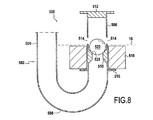
図8は、本発明のもう1つの実施形態を構成するフィラー装置500を示している。
FIG. 8 shows a
装置500は、特に、フィラーダクト502、フロート510、およびボール520を備える。
The
フィラーダクト502は、タンクの外部から内部に向かって連続して伸びることを示す管、すなわち、垂直に延在しタンク10の頂壁を通過する(図示せず)第1の直線状部分504、180°の屈曲部を形成する曲がり部分508、および第2の直線状部分506によって構成される。
The
ダクト502の端部は、シャッター512によって塞がれる。
The end of the
屈曲部508のために、直線状部分506は垂直方向に延在し、シャッターは、(タンク10がその通常位置にある場合には)頂部にある。部分506は、同じ高さに位置している流体出口オリフィス504を有する。また、これは、上に記述した肩部216および316と同じ機能を果たす肩部516を有し、すなわち、フロート510の下方へのストロークを制限する。
Because of the
フロート510は、スリーブ状であり、部分506の周りに配置される。これは、流体レベルが線16に達するとすぐ、出口オリフィス514を塞ぎ(このとき、フロート110は図4に示される位置にある)、かつ逆に言えば、流体レベルがより低い場合には流体が通過できるようになるように、フロート110と同じ方法で動作する。
The
ボール520は、本発明の意味では「重い」要素を構成し、すなわち、これは、その逆止機能を果たすことができるようになるボールに作用する重量である。
The
このために、環状アバットメント518が、部分506の内側に配置される。アバットメントは、ボール520が所定の最も低い位置を越えて下方に移動するのを阻止するような方法で配置される。
For this purpose, an
そのうえ、アバットメント518は、ボール520がダクト502を塞ぐことができるように配置される座面528を有する。このように、それ自体の重量の影響によって、ボール520が(これが配置される)部分506の中に下方に移動する場合には、これは、自発的に表面528に配置されるようになり、次いでダクト502を塞ぐ。
In addition, the
逆に言えば、ダクト502が充填のために使用されている間に、ボール520は、流体がオリフィス514を通過できることになるように、出て行く流体の流れによって上昇され、部分506の中に上昇する。このように、それにもかかわらず逆止機能を果たしながら、ボール520は、タンクが充填されることを阻止しない。
Conversely, while the
タンクの充填中に、シャッター512は、ダクト部分506から外に流体によって放出されるボール520を阻止する働きをする。
During the filling of the tank, the
Claims (10)
・タンクの過剰充填を防止するための第1のストッパ(110、210、420、510)、および流体が不所望にタンクから出ることを防止するための第2のストッパ(120、220、320、420、520)と、
・第1のフロートを所定の位置に配置することが第1のストッパを実質的に閉した位置に配置するように、第1のストッパに機械的に接続される第1のフロート(110、210、410、510)と、
・第2のストッパを保持するためのホルダシステム(122、222、422)であり、そのシステムは、流体がタンク充填方向と反対方向にダクトに沿って遅くとも通過し始めるまでに第2のストッパを閉じた位置に配置し、かつ流体が充填方向にダクト沿って通過する場合には、第2のストッパを開位置に配置するように作用する、ホルダシステムと
を備え、
前記ストッパの各々が、これにより流体がダクトに沿って通過できるようになっている開位置にまたはこれがダクトを塞ぐ閉位置に、配置されるのに適している、
流体タンク(10)用の充填装置(100、200、300、400、500)であって、
ホルダシステムが、装置の動作位置において、重い要素(430、520)の重量の影響によって、第2のストッパ(420、520)をその閉位置に恒久的に維持する傾向があるように配置され、
重い要素が、第2のストッパをまた構成するボールまたは重量(520)によって構成され、
ダクトの内部表面が、座部(528)を有し、
ダクトは、装置の通常位置において、重力の影響によって、ボールまたは重量が座部に移動し、それによってダクトを塞ぐ傾向があるように配置され、
座部が、180°に近い角度を形成する屈曲部から下流の充填方向に形成され、
屈曲部、第2のストッパおよび座部がすべて、タンクの内部に配置されることを特徴とする、充填装置。 A filling duct (102, 402, 502);
A first stopper (110, 210, 420, 510) for preventing overfilling of the tank and a second stopper (120, 220, 320, for preventing fluid from undesirably leaving the tank) 420, 520),
A first float (110, 210) mechanically connected to the first stopper, such that placing the first float in place places the first stopper in a substantially closed position; 410, 510),
A holder system (122, 222, 422) for holding the second stopper, which system moves the second stopper before the fluid begins to pass along the duct at the latest in the direction opposite to the tank filling direction. A holder system, which is arranged in a closed position and acts to position the second stopper in the open position when the fluid passes along the duct in the filling direction;
Each of the stoppers is suitable to be placed in an open position, thereby allowing fluid to pass along the duct, or in a closed position where it closes the duct;
A filling device (100, 200, 300, 400, 500) for a fluid tank (10),
The holder system is arranged to tend to permanently maintain the second stopper (420, 520) in its closed position due to the weight of the heavy element (430, 520) in the operating position of the device;
The heavy element is constituted by a ball or weight (520) that also constitutes the second stopper;
The inner surface of the duct has a seat (528);
The duct is placed in the normal position of the device so that under the influence of gravity, the ball or weight moves to the seat and thereby tends to block the duct,
The seat is formed in the filling direction downstream from the bend forming an angle close to 180 ° ;
The bent portion, the second stopper and the seat are all characterized by Rukoto disposed within the tank, the filling device.
Applications Claiming Priority (3)
| Application Number | Priority Date | Filing Date | Title |
|---|---|---|---|
| FR1256623A FR2993255B1 (en) | 2012-07-10 | 2012-07-10 | LIGHTING DEVICE FOR FLUID RESERVOIR |
| FR1256623 | 2012-07-10 | ||
| PCT/FR2013/051607 WO2014009640A1 (en) | 2012-07-10 | 2013-07-05 | Filling device for fluid tank |
Publications (2)
| Publication Number | Publication Date |
|---|---|
| JP2015526660A JP2015526660A (en) | 2015-09-10 |
| JP6359532B2 true JP6359532B2 (en) | 2018-07-18 |
Family
ID=46852246
Family Applications (1)
| Application Number | Title | Priority Date | Filing Date |
|---|---|---|---|
| JP2015521043A Expired - Fee Related JP6359532B2 (en) | 2012-07-10 | 2013-07-05 | Filler device for fluid tank |
Country Status (12)
| Country | Link |
|---|---|
| US (1) | US9561949B2 (en) |
| EP (1) | EP2872401B1 (en) |
| JP (1) | JP6359532B2 (en) |
| KR (1) | KR102100525B1 (en) |
| CN (1) | CN104520193B (en) |
| CA (1) | CA2878835C (en) |
| ES (1) | ES2715319T3 (en) |
| FR (1) | FR2993255B1 (en) |
| IN (1) | IN2015DN00210A (en) |
| PL (1) | PL2872401T3 (en) |
| RU (1) | RU2631757C2 (en) |
| WO (1) | WO2014009640A1 (en) |
Cited By (1)
| Publication number | Priority date | Publication date | Assignee | Title |
|---|---|---|---|---|
| JP7270519B2 (en) | 2019-10-09 | 2023-05-10 | 藤森工業株式会社 | Tunnel tarpaulin |
Families Citing this family (10)
| Publication number | Priority date | Publication date | Assignee | Title |
|---|---|---|---|---|
| FR3019806B1 (en) * | 2014-04-10 | 2016-04-01 | Inergy Automotive Systems Res | TANK WITH VENTILATION CHANNEL WITH COVER. |
| CN108263720B (en) * | 2016-12-30 | 2024-03-22 | 深圳光启梦想科技有限公司 | Leakage-proof device |
| CN108425904A (en) * | 2018-05-14 | 2018-08-21 | 张家港富瑞阀门有限公司 | A kind of novel liquid level control device and its operation principle |
| CN108967131A (en) * | 2018-07-16 | 2018-12-11 | 东莞市联洲知识产权运营管理有限公司 | It is a kind of municipal administration gardens in pneumatic type automatic watering device |
| JP7163678B2 (en) * | 2018-09-06 | 2022-11-01 | 住友ゴム工業株式会社 | On-off valve and puncture repair kit using it |
| RU197800U1 (en) * | 2019-12-26 | 2020-05-28 | Акционерное общество "Технодинамика" | Hydraulic shut-off fueling unit |
| EP4051502A4 (en) * | 2020-01-30 | 2023-08-16 | Hewlett-Packard Development Company, L.P. | Liquid waste container |
| RU2746905C1 (en) * | 2020-06-23 | 2021-04-22 | Российская Федерация, от имени которой выступает Министерство промышленности и торговли Российской Федерации (Минпромторг России) | Method for isolating unmanned aircraft compartment when filling fuel tank and device for using the method |
| US11932411B2 (en) | 2022-05-31 | 2024-03-19 | Pratt & Whitney Canada Corp. | Aircraft engine oil filler apparatus |
| CN115028133B (en) * | 2022-07-20 | 2023-09-19 | 江西盾牌化工有限责任公司 | Butralin production system |
Family Cites Families (39)
| Publication number | Priority date | Publication date | Assignee | Title |
|---|---|---|---|---|
| US1772588A (en) | 1927-07-08 | 1930-08-12 | Petroleum Heat & Power Co | Valve mechanism |
| US1897492A (en) * | 1927-08-03 | 1933-02-14 | Simplex Valve & Meter Co | Flow controller |
| US1878947A (en) * | 1929-02-16 | 1932-09-20 | Willard J Luff | Float |
| US2122866A (en) * | 1935-02-23 | 1938-07-05 | Cherry Burrell Corp | Float valve |
| US2280876A (en) * | 1939-05-19 | 1942-04-28 | Murdock Mfg And Supply Company | Antipollution drinking fountain |
| GB534854A (en) * | 1939-08-19 | 1941-03-20 | Flight Refueling Ltd | Improvements in or relating to delivering mechanism for delivering liquid such as fuel to tanks |
| US2972412A (en) * | 1955-03-25 | 1961-02-21 | Stanley A Lundeen | Float valve and strainer |
| US3089508A (en) * | 1958-10-10 | 1963-05-14 | Culligan Inc | Chemical solution tank and means for controlling chemical dosage |
| US3146788A (en) * | 1961-09-07 | 1964-09-01 | Culligan Inc | Time control brine refill system |
| US3105512A (en) * | 1962-09-17 | 1963-10-01 | Culligan Inc | Safety shut-off valve |
| US3202174A (en) * | 1963-04-25 | 1965-08-24 | Bruner Corp | Float actuated fill valve |
| US3144045A (en) * | 1963-05-23 | 1964-08-11 | Charles Wheatley Company | Internal counterbalanced check valve |
| US3477611A (en) * | 1968-04-03 | 1969-11-11 | Ford Motor Co | Fuel tank having reduced fuel vapor emission |
| US3752355A (en) * | 1971-01-05 | 1973-08-14 | J Weissenbach | Contained volatile liquids vapor retention system |
| US3791404A (en) * | 1972-04-27 | 1974-02-12 | E Stevens | Float valve |
| DD103290A1 (en) * | 1972-05-06 | 1974-01-12 | Klenk Adam | |
| JPS4929770U (en) * | 1972-06-16 | 1974-03-14 | ||
| US3929155A (en) * | 1972-09-11 | 1975-12-30 | Owen L Garretson | Float shut off valve for liquefied petroleum gas tank fillers |
| IN138652B (en) * | 1973-01-23 | 1976-03-06 | E Rao | |
| GB1531502A (en) * | 1976-06-08 | 1978-11-08 | Peglers Ltd | Float valves |
| US4104004A (en) * | 1976-11-12 | 1978-08-01 | The De Laval Separator Company | Air eliminator for pumps |
| GB2105822B (en) * | 1981-07-24 | 1984-12-19 | Messengers | Filler valve for a fluid tank |
| US4701198A (en) * | 1984-03-24 | 1987-10-20 | Toyota Jidosha Kabushiki Kaisha | Fuel tank for use in a motor vehicle |
| US4627460A (en) * | 1984-06-04 | 1986-12-09 | A. D. Smith Corporation | Condensate discharge device for combustion apparatus |
| US4561258A (en) * | 1985-01-24 | 1985-12-31 | Mg Industries | Gravity-fed low pressure cryogenic liquid delivery system |
| US4637426A (en) * | 1985-11-12 | 1987-01-20 | Lyon Ronald J | Fill control valve |
| ATA337785A (en) | 1985-11-20 | 1989-02-15 | Hoerbiger Ventilwerke Ag | CHECK VALVE |
| US4630749A (en) * | 1986-03-18 | 1986-12-23 | General Motors Corporation | Fuel fill tube with vapor vent and overfill protection |
| CA1272659A (en) * | 1986-04-16 | 1990-08-14 | Grenville Kenneth Yuill | Gas-sealing insert for floor drains |
| US4798306A (en) * | 1987-03-04 | 1989-01-17 | General Motors Corporation | Fuel tank venting |
| US4765504A (en) * | 1987-08-31 | 1988-08-23 | General Motors Corporation | Vapor venting valve for vehicle fuel system |
| US4852357A (en) * | 1988-10-14 | 1989-08-01 | Ncr Corporation | Cryogenic liquid pump |
| US5159953A (en) * | 1991-09-11 | 1992-11-03 | Om Industrial Co., Ltd. | Check valve apparatus for fuel tank |
| RU2039681C1 (en) * | 1992-06-29 | 1995-07-20 | Московский вертолетный завод им.М.Л.Миля | Neck for top filling of tank with fuel |
| US5787942A (en) * | 1996-06-14 | 1998-08-04 | Mve, Inc. | Float-type shut off device for a cryogenic storage tank |
| GB2344635B (en) * | 1998-12-09 | 2003-04-30 | Kitz Corp | Ball check valve and pumping apparatus using the check valve |
| US7469725B2 (en) * | 2006-02-22 | 2008-12-30 | Honeywell International Inc. | Method and apparatus for accurately delivering a predetermined amount of fuel to a vehicle |
| US7584766B2 (en) * | 2006-03-07 | 2009-09-08 | Clay And Bailey Manufacturing Company | Overfill prevention valve for shallow tanks |
| GB2468147A (en) * | 2009-02-27 | 2010-09-01 | Agco Sa | Tank filler spout with closure valve |
-
2012
- 2012-07-10 FR FR1256623A patent/FR2993255B1/en active Active
-
2013
- 2013-07-05 PL PL13744700T patent/PL2872401T3/en unknown
- 2013-07-05 IN IN210DEN2015 patent/IN2015DN00210A/en unknown
- 2013-07-05 US US14/413,803 patent/US9561949B2/en active Active
- 2013-07-05 ES ES13744700T patent/ES2715319T3/en active Active
- 2013-07-05 WO PCT/FR2013/051607 patent/WO2014009640A1/en active Application Filing
- 2013-07-05 KR KR1020157002668A patent/KR102100525B1/en active IP Right Grant
- 2013-07-05 CA CA2878835A patent/CA2878835C/en not_active Expired - Fee Related
- 2013-07-05 EP EP13744700.9A patent/EP2872401B1/en active Active
- 2013-07-05 JP JP2015521043A patent/JP6359532B2/en not_active Expired - Fee Related
- 2013-07-05 CN CN201380041572.8A patent/CN104520193B/en not_active Expired - Fee Related
- 2013-07-05 RU RU2015104262A patent/RU2631757C2/en active
Cited By (1)
| Publication number | Priority date | Publication date | Assignee | Title |
|---|---|---|---|---|
| JP7270519B2 (en) | 2019-10-09 | 2023-05-10 | 藤森工業株式会社 | Tunnel tarpaulin |
Also Published As
| Publication number | Publication date |
|---|---|
| RU2015104262A (en) | 2016-08-27 |
| CN104520193B (en) | 2017-03-08 |
| KR20150036309A (en) | 2015-04-07 |
| FR2993255B1 (en) | 2015-07-03 |
| CA2878835A1 (en) | 2014-01-16 |
| PL2872401T3 (en) | 2019-07-31 |
| US9561949B2 (en) | 2017-02-07 |
| IN2015DN00210A (en) | 2015-06-12 |
| ES2715319T3 (en) | 2019-06-03 |
| US20150203343A1 (en) | 2015-07-23 |
| CN104520193A (en) | 2015-04-15 |
| KR102100525B1 (en) | 2020-04-13 |
| EP2872401B1 (en) | 2019-02-13 |
| WO2014009640A1 (en) | 2014-01-16 |
| CA2878835C (en) | 2020-04-07 |
| FR2993255A1 (en) | 2014-01-17 |
| JP2015526660A (en) | 2015-09-10 |
| EP2872401A1 (en) | 2015-05-20 |
| RU2631757C2 (en) | 2017-09-26 |
Similar Documents
| Publication | Publication Date | Title |
|---|---|---|
| JP6359532B2 (en) | Filler device for fluid tank | |
| JP5429112B2 (en) | Full tank control valve device | |
| US20130340890A1 (en) | Overfill prevention valve | |
| JP2012533015A (en) | Vent valve | |
| JP2013504725A (en) | Ventilation valve for cargo tank | |
| DK2964563T3 (en) | SPILLS FOR DISPENSING A LIQUID PRESENT IN A LIQUID CONTAINER | |
| US7891371B2 (en) | Vent valve | |
| EP2631211A1 (en) | Testable overfill prevention valve | |
| US4893643A (en) | Tank vapor vent valve assembly with improved overfill protection | |
| EP2165873A1 (en) | Antitheft device, particularly for preventing drawing of fuel from tanks | |
| RU2688981C2 (en) | Overflow protection valve for storage tank with remote testing | |
| CN107999152B (en) | Self-adaptive bidirectional anti-suck-back device | |
| US10926625B2 (en) | Tank system of a motor vehicle comprising a volume-modifying element | |
| KR100852524B1 (en) | Air vent head | |
| ITPD20080235A1 (en) | VALVE DEVICE FOR FILLING CONTAINERS, IN PARTICULAR TANKS INTENDED TO CONTAIN LIQUEFIED GAS | |
| JP6522443B2 (en) | Fluid storage device | |
| KR102463411B1 (en) | Device for preventing fuel overflow of vehicle fuel system | |
| JP6346866B2 (en) | Accumulated fire extinguisher | |
| JP2016189848A (en) | Pressure accumulation type fire extinguisher | |
| JP2000146014A (en) | Valve device for overfilling prevention | |
| JP3216370U (en) | Accumulated fire extinguisher | |
| KR20230078885A (en) | Overcharge prevention device for cryogenic fuel tank | |
| JP2003185046A (en) | Liquid cut-off valve device | |
| US20080086806A1 (en) | Toilet having a flapper valve closing device | |
| JPS61244622A (en) | Leakless, fire prevention fuel tank |
Legal Events
| Date | Code | Title | Description |
|---|---|---|---|
| A621 | Written request for application examination |
Free format text: JAPANESE INTERMEDIATE CODE: A621 Effective date: 20160617 |
|
| A977 | Report on retrieval |
Free format text: JAPANESE INTERMEDIATE CODE: A971007 Effective date: 20170529 |
|
| A131 | Notification of reasons for refusal |
Free format text: JAPANESE INTERMEDIATE CODE: A131 Effective date: 20170606 |
|
| A601 | Written request for extension of time |
Free format text: JAPANESE INTERMEDIATE CODE: A601 Effective date: 20170831 |
|
| A601 | Written request for extension of time |
Free format text: JAPANESE INTERMEDIATE CODE: A601 Effective date: 20171031 |
|
| A521 | Request for written amendment filed |
Free format text: JAPANESE INTERMEDIATE CODE: A523 Effective date: 20171205 |
|
| TRDD | Decision of grant or rejection written | ||
| A01 | Written decision to grant a patent or to grant a registration (utility model) |
Free format text: JAPANESE INTERMEDIATE CODE: A01 Effective date: 20180522 |
|
| A61 | First payment of annual fees (during grant procedure) |
Free format text: JAPANESE INTERMEDIATE CODE: A61 Effective date: 20180620 |
|
| R150 | Certificate of patent or registration of utility model |
Ref document number: 6359532 Country of ref document: JP Free format text: JAPANESE INTERMEDIATE CODE: R150 |
|
| R250 | Receipt of annual fees |
Free format text: JAPANESE INTERMEDIATE CODE: R250 |
|
| R250 | Receipt of annual fees |
Free format text: JAPANESE INTERMEDIATE CODE: R250 |
|
| LAPS | Cancellation because of no payment of annual fees |