EP2872401B1 - Filling device for fluid tank - Google Patents
Filling device for fluid tank Download PDFInfo
- Publication number
- EP2872401B1 EP2872401B1 EP13744700.9A EP13744700A EP2872401B1 EP 2872401 B1 EP2872401 B1 EP 2872401B1 EP 13744700 A EP13744700 A EP 13744700A EP 2872401 B1 EP2872401 B1 EP 2872401B1
- Authority
- EP
- European Patent Office
- Prior art keywords
- stopper
- fluid
- float
- duct
- tank
- Prior art date
- Legal status (The legal status is an assumption and is not a legal conclusion. Google has not performed a legal analysis and makes no representation as to the accuracy of the status listed.)
- Active
Links
- 239000012530 fluid Substances 0.000 title claims description 91
- 238000011144 upstream manufacturing Methods 0.000 claims description 7
- 230000000694 effects Effects 0.000 claims description 5
- 230000005484 gravity Effects 0.000 claims description 2
- 239000000945 filler Substances 0.000 claims 2
- 238000002347 injection Methods 0.000 description 8
- 239000007924 injection Substances 0.000 description 8
- 239000002828 fuel tank Substances 0.000 description 3
- 239000007788 liquid Substances 0.000 description 3
- 241001080024 Telles Species 0.000 description 2
- 238000006073 displacement reaction Methods 0.000 description 2
- 239000000463 material Substances 0.000 description 2
- 208000031968 Cadaver Diseases 0.000 description 1
- 240000008042 Zea mays Species 0.000 description 1
- 230000006835 compression Effects 0.000 description 1
- 238000007906 compression Methods 0.000 description 1
- 239000003562 lightweight material Substances 0.000 description 1
- 239000007791 liquid phase Substances 0.000 description 1
- 239000000243 solution Substances 0.000 description 1
- 230000001960 triggered effect Effects 0.000 description 1
Images


Classifications
-
- B—PERFORMING OPERATIONS; TRANSPORTING
- B64—AIRCRAFT; AVIATION; COSMONAUTICS
- B64D—EQUIPMENT FOR FITTING IN OR TO AIRCRAFT; FLIGHT SUITS; PARACHUTES; ARRANGEMENT OR MOUNTING OF POWER PLANTS OR PROPULSION TRANSMISSIONS IN AIRCRAFT
- B64D37/00—Arrangements in connection with fuel supply for power plant
- B64D37/02—Tanks
- B64D37/14—Filling or emptying
- B64D37/16—Filling systems
-
- B—PERFORMING OPERATIONS; TRANSPORTING
- B64—AIRCRAFT; AVIATION; COSMONAUTICS
- B64D—EQUIPMENT FOR FITTING IN OR TO AIRCRAFT; FLIGHT SUITS; PARACHUTES; ARRANGEMENT OR MOUNTING OF POWER PLANTS OR PROPULSION TRANSMISSIONS IN AIRCRAFT
- B64D37/00—Arrangements in connection with fuel supply for power plant
- B64D37/005—Accessories not provided for in the groups B64D37/02 - B64D37/28
-
- B—PERFORMING OPERATIONS; TRANSPORTING
- B67—OPENING, CLOSING OR CLEANING BOTTLES, JARS OR SIMILAR CONTAINERS; LIQUID HANDLING
- B67D—DISPENSING, DELIVERING OR TRANSFERRING LIQUIDS, NOT OTHERWISE PROVIDED FOR
- B67D7/00—Apparatus or devices for transferring liquids from bulk storage containers or reservoirs into vehicles or into portable containers, e.g. for retail sale purposes
- B67D7/06—Details or accessories
- B67D7/36—Arrangements of flow- or pressure-control valves
- B67D7/362—Arrangements of flow- or pressure-control valves combined with over-fill preventing means
- B67D7/365—Arrangements of flow- or pressure-control valves combined with over-fill preventing means using floats
-
- F—MECHANICAL ENGINEERING; LIGHTING; HEATING; WEAPONS; BLASTING
- F16—ENGINEERING ELEMENTS AND UNITS; GENERAL MEASURES FOR PRODUCING AND MAINTAINING EFFECTIVE FUNCTIONING OF MACHINES OR INSTALLATIONS; THERMAL INSULATION IN GENERAL
- F16K—VALVES; TAPS; COCKS; ACTUATING-FLOATS; DEVICES FOR VENTING OR AERATING
- F16K15/00—Check valves
- F16K15/02—Check valves with guided rigid valve members
- F16K15/04—Check valves with guided rigid valve members shaped as balls
- F16K15/044—Check valves with guided rigid valve members shaped as balls spring-loaded
-
- F—MECHANICAL ENGINEERING; LIGHTING; HEATING; WEAPONS; BLASTING
- F16—ENGINEERING ELEMENTS AND UNITS; GENERAL MEASURES FOR PRODUCING AND MAINTAINING EFFECTIVE FUNCTIONING OF MACHINES OR INSTALLATIONS; THERMAL INSULATION IN GENERAL
- F16K—VALVES; TAPS; COCKS; ACTUATING-FLOATS; DEVICES FOR VENTING OR AERATING
- F16K31/00—Actuating devices; Operating means; Releasing devices
- F16K31/12—Actuating devices; Operating means; Releasing devices actuated by fluid
- F16K31/18—Actuating devices; Operating means; Releasing devices actuated by fluid actuated by a float
- F16K31/20—Actuating devices; Operating means; Releasing devices actuated by fluid actuated by a float actuating a lift valve
- F16K31/22—Actuating devices; Operating means; Releasing devices actuated by fluid actuated by a float actuating a lift valve with the float rigidly connected to the valve
-
- F—MECHANICAL ENGINEERING; LIGHTING; HEATING; WEAPONS; BLASTING
- F16—ENGINEERING ELEMENTS AND UNITS; GENERAL MEASURES FOR PRODUCING AND MAINTAINING EFFECTIVE FUNCTIONING OF MACHINES OR INSTALLATIONS; THERMAL INSULATION IN GENERAL
- F16K—VALVES; TAPS; COCKS; ACTUATING-FLOATS; DEVICES FOR VENTING OR AERATING
- F16K31/00—Actuating devices; Operating means; Releasing devices
- F16K31/12—Actuating devices; Operating means; Releasing devices actuated by fluid
- F16K31/18—Actuating devices; Operating means; Releasing devices actuated by fluid actuated by a float
- F16K31/30—Actuating devices; Operating means; Releasing devices actuated by fluid actuated by a float actuating a gate valve or sliding valve
-
- B—PERFORMING OPERATIONS; TRANSPORTING
- B60—VEHICLES IN GENERAL
- B60Y—INDEXING SCHEME RELATING TO ASPECTS CROSS-CUTTING VEHICLE TECHNOLOGY
- B60Y2200/00—Type of vehicle
- B60Y2200/50—Aeroplanes, Helicopters
-
- B—PERFORMING OPERATIONS; TRANSPORTING
- B65—CONVEYING; PACKING; STORING; HANDLING THIN OR FILAMENTARY MATERIAL
- B65D—CONTAINERS FOR STORAGE OR TRANSPORT OF ARTICLES OR MATERIALS, e.g. BAGS, BARRELS, BOTTLES, BOXES, CANS, CARTONS, CRATES, DRUMS, JARS, TANKS, HOPPERS, FORWARDING CONTAINERS; ACCESSORIES, CLOSURES, OR FITTINGS THEREFOR; PACKAGING ELEMENTS; PACKAGES
- B65D90/00—Component parts, details or accessories for large containers
- B65D90/22—Safety features
- B65D90/26—Overfill prevention
Definitions
- the invention relates to a filling device for a fluid reservoir, in particular tanks on board aircraft, such as helicopters.
- the filling device here designates a device comprising a filling duct through which the fluid injected into the reservoir passes when the reservoir is filled.
- the device can perform various auxiliary functions to increase the functionality of the tank.
- a tank 10 may comprise a tank body 12, a suction port 14, a filling device 1.
- the dotted line 16 represents the maximum fluid level accepted in the reservoir.
- the internal space located in the tank body 12 above this line 16 should not contain fluid in the liquid phase.
- the filling device 1 which, by its position, prevents the tank 10 can be filled above the line 16.
- the device 1 is placed so that if the filling of the tank is not interrupted beforehand, and that the fluid inside the tank 10 reaches the level of the line 16, any additional quantity of fluid that one tries to inject into the tank 10 is released from that Simply by gravity via the device 1.
- the outlet of the device 1 is disposed at the level (that is to say, the height) of the line 16.
- the outer end of the filling duct located outside the tank body is generally provided to receive a manually manipulable plug, which serves to close the tank. If, when filling the tank, the plug is forgotten, the fluid can escape from the tank inadvertently via the filling device, for example under the effect of vibrations and air turbulence affecting the tank. aircraft.
- the first float when it is below the predetermined position, the first cap is in the open position (possibly only partially open). It is further understood that the movement of the first float causes movement of the first plug, but also subsequently maintains the first plug in the position corresponding to the position adopted by the first float.
- the first float is displaced by the buoyancy that is applied to it when immersed in the fluid contained in the reservoir.
- the first float When filling the tank, the first float is gradually moved upwards by the fluid. It is this displacement which causes the passage of the first plug in the closed position and consequently, the stoppage of the filling of the tank.
- the tank is not necessarily equipped with means that act on the source of fluid outside the tank to stop the filling thereof.
- the function performed by the filling device is to interrupt the entry of fluid into the reservoir, as soon as the fluid level in the reservoir reaches a predetermined level. This interruption is triggered by the closure of the first plug.
- the upstream portion of the filling duct then fills up very rapidly with fluid; it is overflowing.
- the overflow of the filling duct is detected by the person in charge of the filling, and leads the latter to immediately interrupt the filling of the tank. Closing the first plug thus prevents overfilling of the tank.
- the device is generally arranged such that, after the beginning of a passage of fluid in the conduit in a direction opposite to the direction of filling, or before this passage, the system for maintaining the second plug has placed the second plug in the closed position, the holding system keeps the second plug in the closed position, and this in practice until an injection of fluid into the reservoir via the filling conduit.
- the second float and the second plug may be the same part (s).
- the invention applies in particular to a fluid reservoir equipped with a filling device as defined above and consequently to a turbomachine equipped with a reservoir of the latter type.
- the figure 2 represents a fuel tank 10 mounted in a helicopter not shown.
- the filling device is mounted in the upper part of the tank 10, and is not required to be mounted at the maximum filling height of the tank, materialized by the dashed line 16.
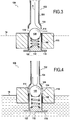
- the Figures 3 and 4 present the lower part of the device 100, in the configurations in which it is placed for fluid levels in the reservoir 10 respectively low and high.
- the device 100 comprises a filling duct comprising a filling duct 102, a first plug 110, to prevent overfilling of the tank, and a second plug 120 to prevent an inadvertent fluid outlet from the tank.
- the filling duct 102 is generally a straight tube fixed through the upper wall of the tank 10 which it passes in a vertical direction in the normal operating position. It is closed at its outer end to the tank by a plug not shown.
- the duct 102 is formed with two main portions: an upstream pipe portion 104, and a downstream pipe portion 106.
- the portion 104 is of smaller diameter than the portion 106. These two portions are connected by a frustoconical junction 108.
- the lower end of the portion 106 is closed by a shutter 112 which the mouth.
- the portion 106 (which constitutes the inner end of the conduit 102, being located inside the reservoir) has four outlet orifices 114 distributed at the same height and at regular angular intervals on the periphery of the portion 106, in the upper part of this portion in the vicinity of the junction 108.
- the fluid when filling the reservoir, the fluid is injected into the conduit 102 in the direction of filling, that is to say from top to bottom; it leaves the conduit by the only possible outlets which are the filling holes 114 (arrow A).
- the cap 110 is a float and has a weight / volume ratio which allows it to float in the fluid contained in the reservoir. It thus constitutes a first float.
- the first cap and the first float thus forming a single piece, they are obviously mechanically connected.
- the float 110 has a sleeve shape and is placed around the conduit portion 106 on which it can move relatively freely.
- the portion 106 thus serves as a guide to the float 110 during its movements.
- the shutter has a ring-shaped locking shoulder 116 which extends radially outwardly around the lower end of the portion 106.
- the shoulder 116 serves to limit the movements of the float 110 downwards, and to prevent the float 110 from coming off the conduit 102 and falling to the bottom of the tank 10.
- the position of the float 110 depends solely on the level of fluid in the tank.
- the float 110 When the fluid level is low, the float 110 rests on the shoulder 116 ( Fig.3 ). The float 210 is then in the so-called 'open' position, the orifices 114 then being open and allowing the injection of fluid into the reservoir.
- the second plug 120 is constituted by a ball.
- the diameter and the material of the ball, and the shape of the joining portion 108, are chosen so that the ball ensures the substantially sealed closure of the conduit 102 when it is pressed against the joining portion 108 (it is then in 'closed' position).
- the portion 108 can thus be called the seat portion for the duct 102.
- the ball 120 is disposed inside the portion 106.
- the ball 120 rests on an end turn of a helical compression spring 122 disposed within the portion 106 and coaxially therewith.
- the lower end of the spring 122 bears on the shutter 112.
- the length of the spring 122 is provided so that the spring permanently bears on the ball 120 and keeps it pressed against the joining portion 108.
- the ball 120 closes the conduit 102 and prevents any fluid outlet from the reservoir.
- the spring 122 is therefore a holding system of the second plug (the ball 120).
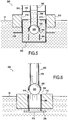
- the figure 5 has a filling device 200 which differs from the device 100 mainly by the way in which the holding system of the second plug is made to perform the function of fluid anti-return, and consequently by the guide means of the first float 210.
- the filling device 200 comprises a fluid retention container 222 disposed around the lower end of the conduit 102.
- the material (and / or structure) of the ball 220 is chosen so that it floats in the fluid contained in the reservoir.
- the container 122 is formed such that when the reservoir 10 is in the normal position, and therefore the conduit 102 extends in the vertical direction, the container 122 remains filled with fluid at least up to the level of the portion 108 .
- the ball 220 is kept permanently submerged in the liquid.
- the buoyancy is therefore exerted on the ball and constitutes a restoring force which tends to press it permanently on the portion 108, and thus maintain it in the closed position.
- the ball 220 closes the conduit 102 and prevents any fluid outlet from the reservoir.
- the shape of the first float 210, which constitutes the first plug, is different from that of the float 110.
- the container 222 has an outer wall 224 of cylindrical shape and vertical axis.
- the walls of the container 222 are sealed except on the one hand, the passage of the conduit 102 through the upper wall 226 of the container, and on the other hand, four outlet orifices 214 arranged on the wall 224 at the same height. .
- the conduit has an end (the portion 106) sealingly connected to the outlet orifices 214; thus, the fluid that passes through the conduit 102 can only exit into the reservoir through the outlet ports 214.
- the container 222 further has an outer shoulder 216 on the wall 224. It plays the same role as the shoulder 116 in the device 100: Namely, it limits the movements down the float 210.
- the float 210 has a sleeve shape and is dimensioned so as to slide around the cylindrical wall 224. It functions in the same manner as the float 110: When the fluid level in the reservoir is low, the float 210 rests on the shoulder 216 and is in the so-called 'open' position, the orifices 214 then being open and thus allowing the injection of fluid into the reservoir.
- the system for holding the second plug can be arranged to serve as a guide for the first float 210.
- the first cap 210 closes the outlet ports 214, thus causing the interruption of the filling of the reservoir.
- the fluid level then stabilizes at line 16 ( Fig.5 ).
- the figure 6 has a filling device 300 integrated with a fluid reservoir 10.
- the device 300 differs from the device 100 mainly by the way in which the holding system of the second plug is made to perform the function of anti-return fluid.
- the tank is an equipment of a turbomachine which, when it operates, keeps the tank at a pressure greater than atmospheric pressure.
- the device 300 exploits the pressure difference between the inside and the outside of the tank to provide the anti-backflow function of fluid.
- the filling duct is formed as in the device 100 with two vertical tube portions 104 and 106, connected by a junction 108.
- the second plug is constituted by a ball 320, disposed in the portion 106 of the filling duct.
- the ball 320 is made of lightweight material. Its diameter is chosen so that it can be pressed on the junction 108 so as to plug the conduit 102.
- the operation of the device 300 is as follows: Unlike the operation of the balls 120 and 220 of the previous embodiments, the ball 320 is not placed in the closed position automatically upon interruption of filling.
- the device 300 indeed, it is an air outlet of the tank 10, or in any case the beginning of a fluid outlet of the tank by the filling duct 102, which places the ball 320 in position closed.
- the ball 320 prevents any fluid outlet of the tank and thus ensures the desired anti-return function.
- the ball 320 then returns to the closed position after the injection of fluid into the reservoir has been interrupted, as soon as a stream of air or fluid tends to resume in the conduit 102.
- the figure 7 has an unclaimed filling device 400.
- the device 400 comprises a filling duct 402 constituted by a simple straight tube, extending through the upper wall of the tank 10.
- the inner end of this tube has a fluid outlet orifice formed in the axis of the tube.
- the device 400 further comprises a float 410, a stopper 420, and a counterweight 430.
- the float 410 (constituting the first float) and the plug 420 (constituting the first plug) are fixed on a lever arm 422 mounted on a pivot 404 fixed with respect to the conduit 402.
- the counterweight 430 is attached to a first end of the lever arm 422 on a first side of the pivot 404.
- the float 410 is attached to the end of the arm 422 opposite its first end.
- the plug 420 is interposed between the pivot 404 and the float 410.
- the device 400 is arranged such that rotation of the lever arm 422 about the pivot 404 moves the plug 420 between the open and closed positions thereof.
- the plug 420 is shown in the open position, that is to say in the fact that it is not plated on the outlet port 414 of the conduit 402.
- the closed position of the plug 420 is the one in which it is plated on the orifice 414.
- the plug 420 is both the first and the second plug within the meaning of the invention. This is made possible by the fact that the actions on the one hand of the first float 410, and on the other hand of the holding system provided in the device 400, accumulate to appropriately place the plug 420 in the open or closed position, and this as follows: Outside the filling periods, and if the fluid level in the reservoir is sufficiently low, the position of the lever arm 422 is dictated by the moment when the float 410 opens and the closing moment of the counterweight 430, resulting in particular from their respective weights. These moments are so named because the moment applied by the counterweight 430 to the lever arm 422 tends to place the plug 420 in the closed position, while that generated by the float 410 tends to place the plug 420 in the open position.
- the float 410 and the counterweight 430 are dimensioned and positioned to such that the closing moment of the counterweight 430 is preponderant in front of the opening moment of the Accordingly, in this situation, the lever arm 422 holds the cap 420 in the closed position.
- the plug 420 performs a fluid anti-return function.
- the fluid level rises in the reservoir. From a certain level, the float 410 comes into contact with the fluid and begins to float and rise. As the float 410 is held by the lever arm 422, it starts a rotation around the pivot 404.
- the float 410 In these circumstances, namely when the float 420 floats on the surface of the fluid, the float 410 generates a closing moment, and no longer an opening, which moment is added to that of the counterweight 430.
- the counterweight 430, the float 410, the pivot 404 and the arm 422 are arranged and dimensioned so that the closing moment resulting from the addition of the moments of the counterweight 430 and the float 410 is greater than the opening moment generated by the fluid pressure exerted on the plug 420 as soon as the fluid level reaches a desired maximum level (line 16).
- the device 400 fulfills the desired function of prohibiting the excessive filling of the tank 10.
- the figure 8 has a filling device 500 according to the invention.
- the device 500 comprises in particular a filling duct 502, a float 510, a ball 520.
- the filling duct 502 is constituted by a tube successively presenting from the outside inside the tank: a first straight portion 504, extending vertically and passing through the upper wall of the tank 10 (not shown), a bent portion 508 forming a bend at 180 °, and a second straight portion 506.
- the end of the conduit 502 is plugged by a shutter 512.
- the straight portion 506 extends in the vertical direction, the shutter being at the top (in the normal position of the tank 10).
- the portion 506 has fluid outlet orifices 514 located at the same height. It also comprises a shoulder 516 which plays the same role as the shoulders 216 and 316, namely to limit the stroke down of the float 510.
- the float 510 has a sleeve shape and is arranged around the portion 506. It operates in the same manner as the float 110, so as to plug the outlet orifices 514 as soon as the fluid level reaches the line 16 (the float 110 being then in the position that is represented on the figure 4 ), and conversely to allow the passage of fluid when the fluid level is lower.
- the ball 520 constitutes in the sense of the invention a heavy element, in the sense that it is the weight exerted on the ball that will allow it to perform its anti-return function.
- annular stop 518 is arranged to prevent the ball 520 to go beyond a predetermined maximum lower position.
- the abutment 518 comprises a seat surface 528 arranged such that the ball 520 can plug the conduit 502.
- the ball 520 under the effect of its weight goes down in the portion 506 (in which it is placed ), it is positioned spontaneously on the surface 528, and then closes the conduit 502.
- the shutter 512 serves, during filling of the reservoir, to prevent the ball 520 is ejected by the fluid outside the conduit portion 506.
Landscapes
- Engineering & Computer Science (AREA)
- General Engineering & Computer Science (AREA)
- Mechanical Engineering (AREA)
- Aviation & Aerospace Engineering (AREA)
- Filling Or Discharging Of Gas Storage Vessels (AREA)
- Loading And Unloading Of Fuel Tanks Or Ships (AREA)
- Float Valves (AREA)
- Cooling, Air Intake And Gas Exhaust, And Fuel Tank Arrangements In Propulsion Units (AREA)
- Check Valves (AREA)
Description
L'invention concerne un dispositif d'emplissage pour réservoir de fluide, en particulier les réservoirs embarqués à bord d'aéronefs, tels que des hélicoptères. Le dispositif d'emplissage désigne ici un dispositif comprenant un conduit d'emplissage par lequel passe le fluide injecté dans le réservoir lorsque le réservoir est rempli. Le dispositif peut remplir diverses fonctions auxiliaires pour augmenter la fonctionnalité du réservoir.The invention relates to a filling device for a fluid reservoir, in particular tanks on board aircraft, such as helicopters. The filling device here designates a device comprising a filling duct through which the fluid injected into the reservoir passes when the reservoir is filled. The device can perform various auxiliary functions to increase the functionality of the tank.
A bord d'aéronefs, des exigences de sécurité peuvent conduire à imposer que la présence d'un ciel gazeux soit assurée en permanence au-dessus du fluide à l'état liquide, à l'intérieur du réservoir.On board aircraft, safety requirements can lead to the requirement that the presence of a gaseous sky be ensured permanently above the fluid in the liquid state, inside the tank.
De manière connue, pour atteindre ce résultat et comme le montre la
Dans le réservoir 10, c'est le dispositif d'emplissage 1 qui, par sa position, empêche que le réservoir 10 puisse être rempli au-dessus de la ligne 16. Dans ce but, le dispositif 1 est placé de telle sorte que si le remplissage du réservoir n'est pas interrompu préalablement, et que le fluide à l'intérieur du réservoir 10 atteint le niveau de la ligne 16, toute quantité supplémentaire de fluide que l'on essaie d'injecter dans le réservoir 10 ressort de celui-ci simplement par gravité via le dispositif 1. En effet, l'orifice de sortie du dispositif 1 est disposé au niveau (c'est-à-dire à la hauteur) de la ligne 16.In the
Cette solution technique pour empêcher le remplissage excessif du réservoir présente l'inconvénient qu'elle impose au dispositif de remplissage d'être disposé à la hauteur maximale de fluide que l'on veut avoir dans le réservoir (hauteur matérialisée sur la
Par ailleurs, en général, l'extrémité externe du conduit d'emplissage située à l'extérieur du corps de réservoir est en général prévue pour recevoir un bouchon manipulable à la main, qui sert à fermer le réservoir. Si au moment de remplir le réservoir, on oublie de remettre en place ce bouchon, le fluide peut s'échapper du réservoir de manière intempestive via le dispositif d'emplissage, par exemple sous l'effet de vibrations et de turbulences aériennes affectant l'aéronef.Furthermore, in general, the outer end of the filling duct located outside the tank body is generally provided to receive a manually manipulable plug, which serves to close the tank. If, when filling the tank, the plug is forgotten, the fluid can escape from the tank inadvertently via the filling device, for example under the effect of vibrations and air turbulence affecting the tank. aircraft.
Il existe donc un besoin pour un dispositif d'emplissage de fluide qui, tout en restant relativement simple :
- assure une protection contre le sur-remplissage en assurant que l'injection de fluide dans le réservoir ne peut entraîner que le niveau de fluide dans le réservoir excède un niveau prédéterminé et cela, sans astreindre néanmoins le dispositif de remplissage à être agencé à une hauteur spécifique prédéterminée par rapport au corps de réservoir ; et
- assure automatiquement une fonction d'anti-retour, c'est-à-dire empêche la sortie intempestive de fluide hors du réservoir via le dispositif d'emplissage.
- provides protection against overfilling by ensuring that the injection of fluid into the reservoir can cause that the fluid level in the reservoir exceeds a predetermined level and this, without, however, compelling the filling device to be arranged at a height specific predetermined with respect to the tank body; and
- automatically provides a non-return function, that is to say prevents the inadvertent release of fluid out of the tank via the filling device.
Cet objectif est atteint grâce au moyen d'un dispositif d'emplissage pour réservoir de fluide selon la revendication 1.This objective is achieved by means of a filling device for a fluid reservoir according to claim 1.
Concernant le premier flotteur, on comprend que lorsqu'il est en deçà de la position prédéterminée, le premier bouchon est en position ouverte (éventuellement seulement partiellement ouverte). On comprend de plus que le déplacement du premier flotteur provoque le déplacement du premier bouchon, mais également par la suite maintient le premier bouchon dans la position qui correspond à la position adoptée par le premier flotteur.Regarding the first float, it is understood that when it is below the predetermined position, the first cap is in the open position (possibly only partially open). It is further understood that the movement of the first float causes movement of the first plug, but also subsequently maintains the first plug in the position corresponding to the position adopted by the first float.
Naturellement, le premier flotteur est déplacé par la poussée d'Archimède qui s'applique sur lui lorsqu'il est immergé dans le fluide contenu dans le réservoir.Naturally, the first float is displaced by the buoyancy that is applied to it when immersed in the fluid contained in the reservoir.
Lors du remplissage du réservoir, le premier flotteur est peu à peu déplacé vers le haut par le fluide. C'est ce déplacement qui provoque le passage du premier bouchon en position fermée et par suite, l'arrêt de l'emplissage du réservoir.When filling the tank, the first float is gradually moved upwards by the fluid. It is this displacement which causes the passage of the first plug in the closed position and consequently, the stoppage of the filling of the tank.
Par ailleurs, le réservoir n'est pas nécessairement équipé de moyens qui agissent sur la source de fluide à l'extérieur du réservoir pour arrêter le remplissage de celui-ci. Avantageusement, la fonction réalisée par le dispositif d'emplissage est d'interrompre l'entrée de fluide dans le réservoir, dès que le niveau de fluide dans le réservoir atteint un niveau prédéterminé. Cette interruption est déclenchée par la fermeture du premier bouchon.Furthermore, the tank is not necessarily equipped with means that act on the source of fluid outside the tank to stop the filling thereof. Advantageously, the function performed by the filling device is to interrupt the entry of fluid into the reservoir, as soon as the fluid level in the reservoir reaches a predetermined level. This interruption is triggered by the closure of the first plug.
Au moment où le premier bouchon se ferme, dans la plupart des modes de réalisation la portion amont du conduit d'emplissage se remplit alors très rapidement de fluide ; elle vient donc à déborder. Le débordement du conduit d'emplissage est détecté par la personne en charge du remplissage, et conduit celle-ci à interrompre immédiatement l'emplissage du réservoir. La fermeture du premier bouchon permet donc d'éviter le sur-remplissage du réservoir.At the moment when the first stopper closes, in most embodiments the upstream portion of the filling duct then fills up very rapidly with fluid; it is overflowing. The overflow of the filling duct is detected by the person in charge of the filling, and leads the latter to immediately interrupt the filling of the tank. Closing the first plug thus prevents overfilling of the tank.
D'autre part, le dispositif est en général agencé de telle sorte que, après que au commencement d'un passage de fluide dans le conduit dans un sens opposé au sens d'emplissage, ou préalablement à ce passage, le système de maintien du deuxième bouchon a placé le deuxième bouchon en position fermée, le système de maintien maintient le deuxième bouchon en position fermée, et cela en pratique jusqu'à une injection de fluide dans le réservoir via le conduit d'emplissage.On the other hand, the device is generally arranged such that, after the beginning of a passage of fluid in the conduit in a direction opposite to the direction of filling, or before this passage, the system for maintaining the second plug has placed the second plug in the closed position, the holding system keeps the second plug in the closed position, and this in practice until an injection of fluid into the reservoir via the filling conduit.
Les dispositions suivantes peuvent être adoptées, seules ou en combinaison :
- le premier flotteur et le premier bouchon peuvent être la ou les même(s) pièce(s), ce qui limite le nombre de pièces.
- le conduit peut présenter une extrémité liée de manière étanche à au moins un orifice de sortie, et en position fermée, le premier bouchon bouche ledit au moins un orifice de sortie. Le ou les orifices de sortie ainsi ne font pas partie du conduit lui-même, mais en revanche sont liés de manière étanche à celui-ci.
- le dispositif peut comporter un guide apte à guider le premier flotteur en translation ; ce guide peut par exemple être constitué par une portion tubulaire du conduit autour de laquelle est disposé le premier flotteur, qui présente par exemple une forme de manchon. C'est un moyen particulièrement simple de réalisation du flotteur.
- le conduit peut comporter au moins un orifice de sortie de fluide ; le premier flotteur et le premier bouchon peuvent être fixés sur un bras de levier monté sur un pivot fixe par rapport au conduit ; le dispositif peut être alors agencé de telle sorte qu'une rotation du bras de levier autour du pivot déplace le premier bouchon entre les positions ouverte et fermée de celui-ci. Le levier présente l'avantage de démultiplier la force exercée sur le premier bouchon.
- le système de maintien peut être apte à maintenir le deuxième bouchon fermé ou du moins sensiblement fermé même lorsque la portion amont du conduit est remplie de fluide. L'expression 'sensiblement fermé' signifie ici qu'un faible débit de fuite est acceptable, dans la mesure où il reste inférieur à 20% du débit de remplissage habituel du réservoir.
- le système de maintien peut être configuré pour mettre en oeuvre une force de rappel choisie dans le groupe comprenant une pression de gaz, une force élastique par exemple d'un ressort, une poussée d'Archimède, un poids, une force magnétique ou électrique.
- le système de maintien peut comporter un élément élastique, par exemple un ressort.
- le deuxième bouchon peut être agencé de telle sorte que, si une pression dans le réservoir est supérieure à une pression à l'extérieur du réservoir, la différence de pression entre le réservoir et l'extérieur du réservoir maintienne le deuxième bouchon en position fermée.
- lorsque le premier flotteur est placé dans la position prédéterminée indiquée précédemment, le premier bouchon reste en position sensiblement fermée et cela même lorsqu'une portion amont du conduit, située en amont du premier bouchon suivant la direction d'emplissage, est remplie de fluide.
- the first float and the first plug may be the same part (s), which limits the number of parts.
- the duct may have an end sealingly connected to at least one outlet, and in the closed position, the first plug closes said at least one outlet. The outlet orifice (s) thus do not form part of the duct itself, but on the other hand are tightly connected to it.
- the device may comprise a guide capable of guiding the first float in translation; this guide may for example be constituted by a tubular portion of the conduit around which is disposed the first float, which has for example a sleeve shape. This is a particularly simple way of producing the float.
- the conduit may include at least one fluid outlet; the first float and the first cap can be attached to a lever arm mounted on a fixed pivot relative to the conduit; the device can then be arranged such that rotation of the lever arm about the pivot moves the first plug between the open and closed positions thereof. The lever has the advantage of multiplying the force exerted on the first plug.
- the holding system may be able to hold the second plug closed or at least substantially closed even when the upstream portion of the conduit is filled with fluid. The term 'substantially closed' means here that a low leakage rate is acceptable, insofar as it remains less than 20% of the usual filling rate of the tank.
- the holding system may be configured to implement a biasing force selected from the group consisting of a gas pressure, an elastic force such as a spring, an Archimedean thrust, a weight, a magnetic or electric force.
- the holding system may comprise an elastic element, for example a spring.
- the second cap may be arranged such that, if a pressure in the reservoir is greater than a pressure outside the reservoir, the pressure difference between the reservoir and the outside of the reservoir keeps the second cap in the closed position.
- when the first float is placed in the predetermined position indicated above, the first plug remains in substantially closed position and this even when an upstream portion of the conduit, located upstream of the first plug in the filling direction, is filled with fluid.
Les perfectionnements envisagés précédemment peuvent être également mis en oeuvre dans ce dernier mode de réalisation, dans la mesure où ils sont techniquement compatibles.The improvements envisaged previously can also be implemented in this last embodiment, to the extent that they are technically compatible.
En outre, dans ce mode de réalisation le deuxième flotteur et le deuxième bouchon peuvent être la ou les même(s) pièce(s).In addition, in this embodiment the second float and the second plug may be the same part (s).
L'invention s'applique notamment à un réservoir de fluide équipé d'un dispositif d'emplissage tel que défini précédemment et par suite, à une turbomachine équipée d'un réservoir de ce dernier type.The invention applies in particular to a fluid reservoir equipped with a filling device as defined above and consequently to a turbomachine equipped with a reservoir of the latter type.
L'invention sera bien comprise et ses avantages apparaîtront mieux à la lecture de la description détaillée qui suit, de modes de réalisation représentés à titre d'exemples non limitatifs. La description se réfère aux dessins annexés, sur lesquels :
- la
figure 1 est une vue schématique en coupe verticale d'un réservoir de carburant connu pour hélicoptère ; - la
figure 2 est une vue schématique en coupe verticale d'un réservoir de carburant pour hélicoptère comprenant un dispositif d'emplissage non revendiqué ; - les
figures 3 et 4 sont des vues schématiques partielles en coupe verticale du dispositif d'emplissage représenté sur lafigure 2 , dans deux configurations d'exploitation ; - la
figure 5 est une vue schématique partielle en coupe verticale d'un dispositif d'emplissage non revendiqué ; - la
figure 6 est une vue schématique partielle en coupe verticale d'un dispositif d'emplissage non revendiqué ; - la
figure 7 est une vue schématique partielle en coupe verticale d'un dispositif d'emplissage non revendiqué ; - la
figure 8 est une vue schématique partielle en coupe verticale d'un dispositif d'emplissage selon l'invention.
- the
figure 1 is a schematic vertical sectional view of a known fuel tank for a helicopter; - the
figure 2 is a schematic vertical sectional view of a helicopter fuel tank including an unclaimed filling device; - the
Figures 3 and 4 are partial schematic views in vertical section of the filling device shown in FIG.figure 2 in two operating configurations; - the
figure 5 is a partial diagrammatic view in vertical section of an unclaimed filling device; - the
figure 6 is a partial diagrammatic view in vertical section of an unclaimed filling device; - the
figure 7 is a partial diagrammatic view in vertical section of an unclaimed filling device; - the
figure 8 is a partial schematic view in vertical section of a filling device according to the invention.
Dans ces figures, les éléments correspondant ou identiques dans différents modes de réalisation portent le même signe de référence et sont en général décrits une seule fois.In these figures, the corresponding or identical elements in different embodiments bear the same reference sign and are generally described only once.
La
Sur celui-ci est monté un dispositif d'emplissage 100. Avantageusement, le dispositif d'emplissage est monté en partie supérieure du réservoir 10, et n'est pas astreint à être monté à la hauteur maximale de remplissage du réservoir, matérialisée par la ligne de pointillés 16.On it is mounted a
Les
Le dispositif 100 comporte un conduit d'emplissage comprenant un conduit d'emplissage 102, un premier bouchon 110, pour empêcher le sur-remplissage du réservoir, et un deuxième bouchon 120 pour empêcher une sortie de fluide intempestive du réservoir.The
Le conduit d'emplissage 102 est globalement un tube rectiligne fixé à travers la paroi supérieure du réservoir 10 qu'il traverse suivant une direction verticale en position normale d'exploitation. Il est fermé à son extrémité externe au réservoir par un bouchon non représenté.The filling
Le conduit 102 est formé avec deux portions principales : une portion de tube amont 104, et une portion de tube aval 106. La portion 104 est de plus petit diamètre que la portion 106. Ces deux portions sont reliées par une jonction tronconique 108.The
L'extrémité inférieure de la portion 106 est fermée par un obturateur 112 qui la bouche.The lower end of the
La portion 106 (qui constitue l'extrémité interne du conduit 102, étant située à l'intérieur du réservoir) comporte quatre orifices de sortie 114 répartis à même hauteur et à des intervalles angulaires réguliers sur la périphérie de la portion 106, en partie haute de cette portion au voisinage de la jonction 108.The portion 106 (which constitutes the inner end of the
Aussi, lors du remplissage du réservoir, le fluide est injecté dans le conduit 102 suivant la direction d'emplissage, c'est-à-dire du haut vers le bas ; il sort du conduit par les seules issues possibles qui sont les orifices de remplissage 114 (flèche A).Also, when filling the reservoir, the fluid is injected into the
Le bouchon 110 est un flotteur et présente un rapport poids/volume qui lui permet de flotter dans le fluide contenu dans le réservoir. Il constitue ainsi un premier flotteur. Le premier bouchon et le premier flotteur ne formant ainsi qu'une seule et même pièce, ils sont bien évidemment reliés mécaniquement.The
Le flotteur 110 a une forme de manchon et est placé autour de la portion de conduit 106 sur laquelle il peut se déplacer relativement librement. La portion 106 sert ainsi de guide au flotteur 110 lors de ses déplacements.The
L'obturateur présente un épaulement de blocage 116, en forme de couronne, qui s'étend radialement vers l'extérieur autour de l'extrémité inférieure de la portion 106.The shutter has a ring-shaped
L'épaulement 116 sert à limiter les déplacements du flotteur 110 vers le bas, et à empêcher que le flotteur 110 ne se détache du conduit 102 et ne tombe au fond du réservoir 10.The
Pendant l'exploitation du réservoir, la position du flotteur 110 dépend uniquement du niveau de fluide dans le réservoir.During the operation of the tank, the position of the
Lorsque le niveau de fluide est bas, le flotteur 110 repose sur l'épaulement 116 (
Lorsque le niveau du fluide est suffisant pour soulever le flotteur 110 celui-ci se soulève et coulisse vers le haut en étant guidé autour du conduit 102.When the level of the fluid is sufficient to lift the
Du fait de ce déplacement, il se place alors progressivement au regard des orifices de sortie 114 et les bouche progressivement.Because of this displacement, it is then gradually placed at the
Lorsqu'il bouche complètement les orifices 114, le conduit 102 est bouché et l'emplissage du réservoir 10 s'arrête. Le flotteur 110 se stabilise au niveau de la ligne 16 dans la position dite position fermée (
On note que lorsque le flotteur 110 se stabilise ainsi au niveau de la ligne 16 et bouche le conduit 102 au niveau des orifices 114, le conduit 102 est plein de fluide. La pression de la colonne de fluide ainsi contenue dans le conduit 102 ne tend pas à faire descendre le flotteur 110 (en tant que premier bouchon), et le flotteur 110 reste en position fermée.It is noted that when the
Le deuxième bouchon 120 est constitué par une bille. Le diamètre et le matériau de la bille, et la forme de la portion de jonction 108, sont choisis de telle sorte que la bille assure la fermeture sensiblement étanche du conduit 102 lorsqu'elle est plaquée contre la portion de jonction 108 (elle est alors en position 'fermée'). La portion 108 peut ainsi être appelée portion de siège pour le conduit 102.The
La bille 120 est disposée à l'intérieur de la portion 106. La bille 120 repose sur une spire d'extrémité d'un ressort hélicoidal de compression 122 disposé à l'intérieur de la portion 106 et coaxialement à celle-ci. L'extrémité inférieure du ressort 122 est en appui sur l'obturateur 112.The
La longueur du ressort 122 est prévue pour que le ressort exerce en permanence un appui sur la bille 120 et la maintienne plaquée sur la portion de jonction 108.The length of the
Par suite, sauf pendant les périodes de remplissage du réservoir, la bille 120 obture le conduit 102 et empêche toute sortie de fluide du réservoir.Consequently, except during the filling periods of the reservoir, the
Inversement pendant les périodes de remplissage du réservoir, la pression de fluide sur la bille fait légèrement descendre celle-ci, permettant le passage de fluide dans le conduit 102 au niveau de la portion 108 (
Le ressort 122 constitue donc un système de maintien du deuxième bouchon (la bille 120).The
La
Le dispositif de remplissage 200 comporte un récipient de rétention de fluide 222, disposé autour de l'extrémité inférieure du conduit 102.The filling
Le matériau (et/ou la structure) de la bille 220 est choisi de telle sorte que celle-ci flotte dans le fluide contenu dans le réservoir.The material (and / or structure) of the
Le récipient 122 est formé de telle sorte que lorsque le réservoir 10 est en position normale, et par conséquent que le conduit 102 s'étend suivant la direction verticale, le récipient 122 reste rempli de fluide au moins jusqu'au niveau de la portion 108.The
Par conséquent, la bille 220 est maintenue en permanence submergée dans le liquide.Therefore, the
La poussée d'Archimède s'exerce donc sur la bille et constitue une force de rappel qui tend à plaquer celle-ci en permanence sur la portion 108, et à la maintenir ainsi en position fermée.The buoyancy is therefore exerted on the ball and constitutes a restoring force which tends to press it permanently on the
Par suite, sauf pendant les périodes de remplissage du réservoir, la bille 220 obture le conduit 102 et empêche toute sortie de fluide du réservoir.As a result, except during the filling periods of the reservoir, the
Inversement pendant les périodes de remplissage du réservoir, la pression de fluide sur la bille fait légèrement descendre celle-ci, permettant le passage de fluide dans le conduit 102 au niveau de la portion 108.Conversely, during the filling periods of the reservoir, the fluid pressure on the ball causes it to descend slightly, allowing the passage of fluid in the
D'autre part, du fait de la présence du récipient 222, la forme du premier flotteur 210, qui constitue le premier bouchon, est différente de celle du flotteur 110.On the other hand, because of the presence of the
Le récipient 222 présente une paroi extérieure 224 de forme cylindrique et d'axe vertical. Les parois du récipient 222 sont étanches à l'exception d'une part, du passage du conduit 102 à travers la paroi supérieure 226 du récipient, et d'autre part, de quatre orifices de sortie 214 disposés sur la paroi 224 à même hauteur.The
Par suite, le conduit présente une extrémité (la portion 106) liée de manière étanche aux orifices de sortie 214 ; ainsi, le fluide qui passe par le conduit 102 ne peut sortir dans le réservoir qu'en passant à travers les orifices de sortie 214.As a result, the conduit has an end (the portion 106) sealingly connected to the
Le récipient 222 présente en outre un épaulement externe 216 sur la paroi 224. Celui-ci joue le même rôle que l'épaulement 116 dans le dispositif 100 : A savoir, il limite les déplacements vers le bas du flotteur 210.The
Le flotteur 210 a une forme de manchon et est dimensionné de manière à pouvoir coulisser autour de la paroi cylindrique 224. Il fonctionne de la même manière que le flotteur 110 :
Lorsque le niveau de fluide dans le réservoir est bas, le flotteur 210 repose sur l'épaulement 216 et est en position dite 'ouverte', les orifices 214 étant alors ouverts et permettant ainsi l'injection de fluide dans le réservoir.The
When the fluid level in the reservoir is low, the
Lorsque le niveau de fluide est suffisant pour soulever et faire flotter le flotteur 210, celui-ci se soulève de l'épaulement 216 et se déplace vers le haut en coulissant autour du récipient 222.When the fluid level is sufficient to lift and float the
On constate donc que le système de maintien du deuxième bouchon (comprenant notamment le récipient 222) peut être agencé de manière à servir de guide au premier flotteur 210.It can therefore be seen that the system for holding the second plug (including in particular the container 222) can be arranged to serve as a guide for the
Lorsque le niveau du fluide dans le réservoir est suffisamment élevé, le premier bouchon 210 bouche les orifices de sortie 214, entraînant ainsi l'interruption du remplissage du réservoir. Le niveau de fluide se stabilise alors au niveau de la ligne 16 (
La
Dans ce mode de réalisation, le réservoir est un équipement d'une turbomachine qui, lorsqu'elle fonctionne, maintient le réservoir à une pression supérieure à la pression atmosphérique.In this embodiment, the tank is an equipment of a turbomachine which, when it operates, keeps the tank at a pressure greater than atmospheric pressure.
Le dispositif 300 exploite la différence de pression entre l'intérieur et l'extérieur du réservoir pour assurer la fonction anti-retour de fluide.The
Dans le dispositif 300, le conduit d'emplissage est formé comme dans le dispositif 100 avec deux portions de tube verticales 104 et 106, reliées par une jonction 108.In the
Le deuxième bouchon est constitué par une bille 320, disposée dans la portion 106 du conduit d'emplissage. La bille 320 est réalisée en matériau léger. Son diamètre est choisi de telle sorte qu'elle puisse se plaquer sur la jonction 108 de manière à boucher le conduit 102.The second plug is constituted by a
Lorsque la bille 320 n'est pas placée sur la jonction 108, sous l'effet de son poids la bille descend dans la portion de tube 106 et se place sur un obturateur 312 prévu pour boucher l'extrémité interne de la portion 106. Elle est alors en position dite 'ouverte'.When the
Le fonctionnement du dispositif 300 est le suivant :
Contrairement au fonctionnement des billes 120 et 220 des modes de réalisation précédents, la bille 320 ne se place pas en position fermée automatiquement dès l'interruption du remplissage.The operation of the
Unlike the operation of the
Dans le dispositif 300 en effet, c'est une sortie d'air du réservoir 10, ou en tout état de cause le commencement d'une sortie de fluide du réservoir par le conduit d'emplissage 102, qui place la bille 320 en position fermée.In the
En effet, dès qu'une sortie d'air ou de fluide tend à se produire via le conduit d'emplissage, ce flux entraîne immédiatement la bille 320. Celle-ci se plaque sur la jonction 108 et bouche ainsi le conduit 102. La bille 320 reste alors maintenue en position par la différence de pression régnant entre l'intérieur et l'extérieur du réservoir.Indeed, as soon as an air outlet or fluid tends to occur via the filling duct, this flow immediately causes the
Grâce à cela, la bille 320 empêche toute sortie de fluide du réservoir et assure ainsi la fonction anti-retour souhaitée.With this, the
Inversement, dès que l'on injecte du fluide dans le réservoir pour le remplir, la pression du fluide sur la bille 320 décolle celle-ci de la jonction 108, ce qui fait retomber la bille sur l'obturateur 312 en position ouverte, position dans laquelle l'injection de fluide dans le réservoir 10 est possible.Conversely, as soon as fluid is injected into the reservoir to fill it, the pressure of the fluid on the
La bille 320 revient ensuite en position fermée après que l'injection de fluide dans le réservoir a été interrompue, dès qu'un courant d'air ou de fluide tend à reprendre dans le conduit 102.The
La
Le dispositif 400 comporte un conduit d'emplissage 402 constitué par un simple tube droit, s'étendant à travers la paroi supérieure du réservoir 10.The
L'extrémité interne de ce tube présente un orifice de sortie de fluide formé dans l'axe du tube.The inner end of this tube has a fluid outlet orifice formed in the axis of the tube.
Le dispositif 400 comporte en outre un flotteur 410, un bouchon 420, et un contrepoids 430.The
Le flotteur 410 (constituant le premier flotteur) et le bouchon 420 (constituant le premier bouchon) sont fixés sur un bras de levier 422 monté sur un pivot 404 fixe par rapport au conduit 402.The float 410 (constituting the first float) and the plug 420 (constituting the first plug) are fixed on a
Le contrepoids 430 est fixé à une première extrémité du bras de levier 422, sur un premier côté du pivot 404.The
Le flotteur 410 est fixé à l'extrémité du bras 422 opposée à sa première extrémité. Le bouchon 420 est interposé entre le pivot 404 et le flotteur 410.The
Le dispositif 400 est agencé de telle sorte qu'une rotation du bras de levier 422 autour du pivot 404 déplace le bouchon 420 entre les positions ouverte et fermée de celui-ci.The
Sur la
La position fermée du bouchon 420 est celle dans laquelle il est plaqué sur l'orifice 414.The closed position of the
Avantageusement, le bouchon 420 est à la fois le premier et le deuxième bouchon au sens de l'invention. Cela est rendu possible par le fait que les actions d'une part du premier flotteur 410, et d'autre part du système de maintien prévu dans le dispositif 400, se cumulent pour placer de manière appropriée le bouchon 420 en position ouverte ou fermée, et cela de la manière suivante :
En dehors des périodes de remplissage, et si le niveau de fluide dans le réservoir est suffisamment bas, la position du bras de levier 422 est dictée par le moment d'ouverture du flotteur 410 et le moment de fermeture du contrepoids 430, résultant notamment de leurs poids respectifs. Ces moments sont nommés ainsi car le moment appliqué par le contrepoids 430 au bras de levier 422 tend à placer le bouchon 420 en position fermée, alors que celui engendré par le flotteur 410 tend à placer le bouchon 420 en position ouverte.Advantageously, the
Outside the filling periods, and if the fluid level in the reservoir is sufficiently low, the position of the
Lorsque le flotteur 410 n'est pas poussé vers le haut par la force d'Archimède exercée par le liquide (du fait que le niveau de fluide dans le réservoir est suffisamment bas), le flotteur 410 et le contrepoids 430 sont dimensionnés et positionnés de telle sorte que le moment de fermeture du contrepoids 430 soit prépondérant devant le moment d'ouverture du flotteur 420. Par suite, dans cette situation, le bras de levier 422 maintient le bouchon 420 en position fermée.When the
Dans cette position, le bouchon 420 remplit une fonction anti-retour de fluide.In this position, the
A contrario, lors du remplissage du réservoir, la pression du fluide injecté dans le conduit 402 et s'exerçant sur le bouchon 420 engendre un moment d'ouverture s'appliquant au bras de levier 422. Ce moment d'ouverture ajouté au moment d'ouverture du flotteur 410 surmonte le moment de fermeture causé par le contrepoids 430, entraîne l'ouverture de l'orifice 414 du conduit 402, et permet l'injection de fluide dans le réservoir.Conversely, during filling of the reservoir, the pressure of the fluid injected into the
Au fur et à mesure que l'on injecte du fluide dans le réservoir, le niveau de fluide s'élève dans le réservoir. A partir d'un certain niveau le flotteur 410 entre en contact avec le fluide et commence à flotter et à s'élever. Comme le flotteur 410 est maintenu par le bras de levier 422, il entame une rotation autour du pivot 404.As fluid is injected into the reservoir, the fluid level rises in the reservoir. From a certain level, the
Dans ces circonstances, à savoir lorsque le flotteur 420 flotte à la surface du fluide, le flotteur 410 engendre un moment de fermeture, et non plus d'ouverture, moment qui par s'ajoute à celui du contrepoids 430.In these circumstances, namely when the
Le contrepoids 430, le flotteur 410, le pivot 404 et le bras 422 sont agencés et dimensionnés de telle sorte que le moment de fermeture résultant de l'addition des moments du contrepoids 430 et du flotteur 410 soit supérieur au moment d'ouverture engendré par la pression de fluide s'exerçant sur le bouchon 420 dès que le niveau de fluide atteint un niveau maximal souhaité (ligne 16).The
Par conséquent, lorsque le niveau de fluide dans le réservoir s'élève, au fur et à mesure du mouvement vers le haut du flotteur 410, le bras de levier 422 pivote.Therefore, as the fluid level in the reservoir rises, as the
Il vient donc un moment auquel l'ouverture 414 se ferme, ce qui provoque l'interruption du remplissage du réservoir. Par cette interruption, le dispositif 400 remplit la fonction souhaitée d'interdiction du remplissage excessif du réservoir 10.There comes a time when the
La
Le dispositif 500 comporte notamment un conduit d'emplissage 502, un flotteur 510, une bille 520.The
Le conduit d'emplissage 502 est constitué par un tube présentant successivement de l'extérieur à l'intérieur du réservoir : une première portion droite 504, s'étendant verticalement et traversant la paroi supérieure du réservoir 10 (non représentée), une portion coudée 508 formant un coude à 180°, et une deuxième portion droite 506.The filling
L'extrémité du conduit 502 est bouchée par un obturateur 512.The end of the
Du fait du coude 508, la portion droite 506 s'étend suivant la direction verticale, l'obturateur étant en haut (en position normale du réservoir 10). La portion 506 comporte des orifices de sortie de fluide 514 situés à une même hauteur. Elle comporte également un épaulement 516 qui joue le même rôle que les épaulements 216 et 316 précédents, à savoir limiter la course vers le bas du flotteur 510.Due to the
Le flotteur 510 a une forme de manchon et est disposé autour de la portion 506. Il fonctionne de la même manière que le flotteur 110, de manière à boucher les orifices de sortie 514 dès que le niveau de fluide atteint la ligne 16 (le flotteur 110 étant alors dans la position qui est représentée sur la
La bille 520 constitue au sens de l'invention un élément pesant, au sens où c'est le poids s'exerçant sur la bille qui va lui permettre de remplir sa fonction anti-retour.The
Dans ce but, à l'intérieur de la portion 506 est aménagé une butée annulaire 518. Celle-ci est agencée de manière à empêcher la bille 520 de descendre au-delà d'une position inférieure maximale prédéterminée.For this purpose, within the
De plus, la butée 518 comporte une surface de siège 528 agencée de telle sorte que la bille 520 puisse boucher le conduit 502. Ainsi, lorsque la bille 520 sous l'effet de son poids descend dans la portion 506 (dans laquelle elle est placée), elle se positionne spontanément sur la surface 528, et obture alors le conduit 502.In addition, the
Inversement lors du remplissage du conduit 502, la bille 520 est soulevée par le flux de fluide sortant et remonte dans la portion 506, jusqu'à permettre le passage de fluide par les orifices 514. Ainsi tout en assurant la fonction d'anti-retour, la bille 520 n'empêche pas l'emplissage du réservoir.Conversely during the filling of the
L'obturateur 512 sert, lors de l'emplissage du réservoir, à empêcher que la bille 520 ne soit éjectée par le fluide hors de la portion de conduit 506.The
Claims (11)
- A filler device (500) for a fluid tank (10), the device comprising:• a filler duct (502);• a first stopper (510), for preventing overfilling of the tank, and a second stopper (520) for preventing fluid from leaving the tank in unwanted manner;• a first float (510) mechanically connected to the first stopper in such a manner that placing the first float in a predetermined position places the first stopper in a substantially closed position; and• a holder system for holding the second stopper, which system acts, no later than the fluid beginning to pass along the duct in a direction opposite to the tank-filling direction, to place the second stopper in the closed position, and when a fluid passes along the duct in the filling direction, to place the second stopper in the open position; and in whicheach of said stoppers is suitable for being placed in an open position in which it allows fluid to pass along the duct, or in a closed position in which it plugs the duct; and
an internal surface of the duct presents a seat portion (528) ;
the device being characterized in that the holder system is arranged in such a manner that in an operating position of the device, under the effect of the weight of a heavy element (520), the holder system tends permanently to maintain the second stopper (520) in its closed position;
the heavy element is constituted by a ball or a weight (520) that also constitutes the second stopper;
the duct is arranged in such a manner that in the normal position of the device, under the effect of gravity, the ball or weight tends to move onto the seat portion and thus to plug the duct; and
the seat portion is formed in a filling direction downstream from a bend forming an angle close to 180°. - A device according to claim 1, wherein the first float and the first stopper are the same part or parts (510).
- A device according to claim 1 or claim 2, in which, in the closed position, the first stopper plugs the duct at said seat portion.
- A device according to any one of claims 1 to 3, wherein the duct presents one end connected in leaktight manner to at least one outlet orifice (514), and in the closed position, the first stopper plugs said at least one outlet orifice.
- A device according to any one of claims 1 to 4, including a guide (506) suitable for guiding the first float to move in translation.
- A device according to claim 5, wherein the guide is constituted by a tubular portion (506) of the duct around which the first float is arranged.
- A device according to claim 6, wherein the first float is in the form of a sleeve.
- A device according to any one of claims 1 to 4, wherein the duct includes at least one fluid outlet orifice;
the first float and the first stopper are fastened on a lever arm mounted on a pivot (404) that is fixed relative to the duct;
the device is arranged in such a manner that pivoting of the lever arm about the pivot moves the first stopper (420) between its open and closed positions. - A device according to any one of claims 1 to 8, wherein the second stopper is arranged in such a manner that, if pressure inside the tank is greater than pressure outside the tank, the pressure difference between the tank and the outside of the tank holds the second stopper in the closed position.
- A device according to any one of claims 1 to 9, wherein when the first float is placed in said predetermined position, the first stopper remains in a substantially closed position, with this continuing even when an upstream portion of the duct, situated upstream from the first stopper in the filling direction, is full of fluid.
- A fluid tank fitted with a device according to any one of claims 1 to 10.
Priority Applications (1)
| Application Number | Priority Date | Filing Date | Title |
|---|---|---|---|
| PL13744700T PL2872401T3 (en) | 2012-07-10 | 2013-07-05 | Filling device for fluid tank |
Applications Claiming Priority (2)
| Application Number | Priority Date | Filing Date | Title |
|---|---|---|---|
| FR1256623A FR2993255B1 (en) | 2012-07-10 | 2012-07-10 | LIGHTING DEVICE FOR FLUID RESERVOIR |
| PCT/FR2013/051607 WO2014009640A1 (en) | 2012-07-10 | 2013-07-05 | Filling device for fluid tank |
Publications (2)
| Publication Number | Publication Date |
|---|---|
| EP2872401A1 EP2872401A1 (en) | 2015-05-20 |
| EP2872401B1 true EP2872401B1 (en) | 2019-02-13 |
Family
ID=46852246
Family Applications (1)
| Application Number | Title | Priority Date | Filing Date |
|---|---|---|---|
| EP13744700.9A Active EP2872401B1 (en) | 2012-07-10 | 2013-07-05 | Filling device for fluid tank |
Country Status (12)
| Country | Link |
|---|---|
| US (1) | US9561949B2 (en) |
| EP (1) | EP2872401B1 (en) |
| JP (1) | JP6359532B2 (en) |
| KR (1) | KR102100525B1 (en) |
| CN (1) | CN104520193B (en) |
| CA (1) | CA2878835C (en) |
| ES (1) | ES2715319T3 (en) |
| FR (1) | FR2993255B1 (en) |
| IN (1) | IN2015DN00210A (en) |
| PL (1) | PL2872401T3 (en) |
| RU (1) | RU2631757C2 (en) |
| WO (1) | WO2014009640A1 (en) |
Families Citing this family (11)
| Publication number | Priority date | Publication date | Assignee | Title |
|---|---|---|---|---|
| FR3019806B1 (en) * | 2014-04-10 | 2016-04-01 | Inergy Automotive Systems Res | TANK WITH VENTILATION CHANNEL WITH COVER. |
| CN108263720B (en) * | 2016-12-30 | 2024-03-22 | 深圳光启梦想科技有限公司 | Leakage-proof device |
| CN108425904A (en) * | 2018-05-14 | 2018-08-21 | 张家港富瑞阀门有限公司 | A kind of novel liquid level control device and its operation principle |
| CN108967131A (en) * | 2018-07-16 | 2018-12-11 | 东莞市联洲知识产权运营管理有限公司 | It is a kind of municipal administration gardens in pneumatic type automatic watering device |
| JP7163678B2 (en) * | 2018-09-06 | 2022-11-01 | 住友ゴム工業株式会社 | On-off valve and puncture repair kit using it |
| JP7270519B2 (en) | 2019-10-09 | 2023-05-10 | 藤森工業株式会社 | Tunnel tarpaulin |
| RU197800U1 (en) * | 2019-12-26 | 2020-05-28 | Акционерное общество "Технодинамика" | Hydraulic shut-off fueling unit |
| CN114981088A (en) * | 2020-01-30 | 2022-08-30 | 惠普发展公司,有限责任合伙企业 | Liquid waste container |
| RU2746905C1 (en) * | 2020-06-23 | 2021-04-22 | Российская Федерация, от имени которой выступает Министерство промышленности и торговли Российской Федерации (Минпромторг России) | Method for isolating unmanned aircraft compartment when filling fuel tank and device for using the method |
| US11932411B2 (en) | 2022-05-31 | 2024-03-19 | Pratt & Whitney Canada Corp. | Aircraft engine oil filler apparatus |
| CN115028133B (en) * | 2022-07-20 | 2023-09-19 | 江西盾牌化工有限责任公司 | Butralin production system |
Family Cites Families (39)
| Publication number | Priority date | Publication date | Assignee | Title |
|---|---|---|---|---|
| US1772588A (en) * | 1927-07-08 | 1930-08-12 | Petroleum Heat & Power Co | Valve mechanism |
| US1897492A (en) * | 1927-08-03 | 1933-02-14 | Simplex Valve & Meter Co | Flow controller |
| US1878947A (en) * | 1929-02-16 | 1932-09-20 | Willard J Luff | Float |
| US2122866A (en) * | 1935-02-23 | 1938-07-05 | Cherry Burrell Corp | Float valve |
| US2280876A (en) * | 1939-05-19 | 1942-04-28 | Murdock Mfg And Supply Company | Antipollution drinking fountain |
| GB534854A (en) * | 1939-08-19 | 1941-03-20 | Flight Refueling Ltd | Improvements in or relating to delivering mechanism for delivering liquid such as fuel to tanks |
| US2972412A (en) * | 1955-03-25 | 1961-02-21 | Stanley A Lundeen | Float valve and strainer |
| US3089508A (en) * | 1958-10-10 | 1963-05-14 | Culligan Inc | Chemical solution tank and means for controlling chemical dosage |
| US3146788A (en) * | 1961-09-07 | 1964-09-01 | Culligan Inc | Time control brine refill system |
| US3105512A (en) * | 1962-09-17 | 1963-10-01 | Culligan Inc | Safety shut-off valve |
| US3202174A (en) * | 1963-04-25 | 1965-08-24 | Bruner Corp | Float actuated fill valve |
| US3144045A (en) * | 1963-05-23 | 1964-08-11 | Charles Wheatley Company | Internal counterbalanced check valve |
| US3477611A (en) * | 1968-04-03 | 1969-11-11 | Ford Motor Co | Fuel tank having reduced fuel vapor emission |
| US3752355A (en) * | 1971-01-05 | 1973-08-14 | J Weissenbach | Contained volatile liquids vapor retention system |
| US3791404A (en) * | 1972-04-27 | 1974-02-12 | E Stevens | Float valve |
| DD103290A1 (en) * | 1972-05-06 | 1974-01-12 | Klenk Adam | |
| JPS4929770U (en) * | 1972-06-16 | 1974-03-14 | ||
| US3929155A (en) * | 1972-09-11 | 1975-12-30 | Owen L Garretson | Float shut off valve for liquefied petroleum gas tank fillers |
| IN138652B (en) * | 1973-01-23 | 1976-03-06 | E Rao | |
| GB1531502A (en) * | 1976-06-08 | 1978-11-08 | Peglers Ltd | Float valves |
| US4104004A (en) * | 1976-11-12 | 1978-08-01 | The De Laval Separator Company | Air eliminator for pumps |
| GB2105822B (en) * | 1981-07-24 | 1984-12-19 | Messengers | Filler valve for a fluid tank |
| US4701198A (en) * | 1984-03-24 | 1987-10-20 | Toyota Jidosha Kabushiki Kaisha | Fuel tank for use in a motor vehicle |
| US4627460A (en) * | 1984-06-04 | 1986-12-09 | A. D. Smith Corporation | Condensate discharge device for combustion apparatus |
| US4561258A (en) * | 1985-01-24 | 1985-12-31 | Mg Industries | Gravity-fed low pressure cryogenic liquid delivery system |
| US4637426A (en) * | 1985-11-12 | 1987-01-20 | Lyon Ronald J | Fill control valve |
| ATA337785A (en) * | 1985-11-20 | 1989-02-15 | Hoerbiger Ventilwerke Ag | CHECK VALVE |
| US4630749A (en) * | 1986-03-18 | 1986-12-23 | General Motors Corporation | Fuel fill tube with vapor vent and overfill protection |
| CA1272659A (en) * | 1986-04-16 | 1990-08-14 | Grenville Kenneth Yuill | Gas-sealing insert for floor drains |
| US4798306A (en) * | 1987-03-04 | 1989-01-17 | General Motors Corporation | Fuel tank venting |
| US4765504A (en) * | 1987-08-31 | 1988-08-23 | General Motors Corporation | Vapor venting valve for vehicle fuel system |
| US4852357A (en) * | 1988-10-14 | 1989-08-01 | Ncr Corporation | Cryogenic liquid pump |
| US5159953A (en) * | 1991-09-11 | 1992-11-03 | Om Industrial Co., Ltd. | Check valve apparatus for fuel tank |
| RU2039681C1 (en) * | 1992-06-29 | 1995-07-20 | Московский вертолетный завод им.М.Л.Миля | Neck for top filling of tank with fuel |
| US5787942A (en) * | 1996-06-14 | 1998-08-04 | Mve, Inc. | Float-type shut off device for a cryogenic storage tank |
| GB2344635B (en) * | 1998-12-09 | 2003-04-30 | Kitz Corp | Ball check valve and pumping apparatus using the check valve |
| US7469725B2 (en) * | 2006-02-22 | 2008-12-30 | Honeywell International Inc. | Method and apparatus for accurately delivering a predetermined amount of fuel to a vehicle |
| US7584766B2 (en) * | 2006-03-07 | 2009-09-08 | Clay And Bailey Manufacturing Company | Overfill prevention valve for shallow tanks |
| GB2468147A (en) * | 2009-02-27 | 2010-09-01 | Agco Sa | Tank filler spout with closure valve |
-
2012
- 2012-07-10 FR FR1256623A patent/FR2993255B1/en active Active
-
2013
- 2013-07-05 JP JP2015521043A patent/JP6359532B2/en not_active Expired - Fee Related
- 2013-07-05 WO PCT/FR2013/051607 patent/WO2014009640A1/en active Application Filing
- 2013-07-05 RU RU2015104262A patent/RU2631757C2/en active
- 2013-07-05 IN IN210DEN2015 patent/IN2015DN00210A/en unknown
- 2013-07-05 CA CA2878835A patent/CA2878835C/en not_active Expired - Fee Related
- 2013-07-05 KR KR1020157002668A patent/KR102100525B1/en active IP Right Grant
- 2013-07-05 EP EP13744700.9A patent/EP2872401B1/en active Active
- 2013-07-05 ES ES13744700T patent/ES2715319T3/en active Active
- 2013-07-05 PL PL13744700T patent/PL2872401T3/en unknown
- 2013-07-05 US US14/413,803 patent/US9561949B2/en active Active
- 2013-07-05 CN CN201380041572.8A patent/CN104520193B/en not_active Expired - Fee Related
Non-Patent Citations (1)
| Title |
|---|
| None * |
Also Published As
| Publication number | Publication date |
|---|---|
| RU2015104262A (en) | 2016-08-27 |
| RU2631757C2 (en) | 2017-09-26 |
| CN104520193A (en) | 2015-04-15 |
| FR2993255B1 (en) | 2015-07-03 |
| KR20150036309A (en) | 2015-04-07 |
| JP2015526660A (en) | 2015-09-10 |
| CN104520193B (en) | 2017-03-08 |
| CA2878835A1 (en) | 2014-01-16 |
| KR102100525B1 (en) | 2020-04-13 |
| FR2993255A1 (en) | 2014-01-17 |
| PL2872401T3 (en) | 2019-07-31 |
| US20150203343A1 (en) | 2015-07-23 |
| US9561949B2 (en) | 2017-02-07 |
| EP2872401A1 (en) | 2015-05-20 |
| JP6359532B2 (en) | 2018-07-18 |
| IN2015DN00210A (en) | 2015-06-12 |
| CA2878835C (en) | 2020-04-07 |
| WO2014009640A1 (en) | 2014-01-16 |
| ES2715319T3 (en) | 2019-06-03 |
Similar Documents
| Publication | Publication Date | Title |
|---|---|---|
| EP2872401B1 (en) | Filling device for fluid tank | |
| EP1172306B1 (en) | Venting system for liquid tank | |
| EP2746733B1 (en) | Metering device with differential pressure | |
| FR2739612A1 (en) | APPARATUS FOR CONTROLLING FUEL TANK VESSELS IN A VEHICLE | |
| EP0433151B1 (en) | Overfilling controller for a fluid storage tank | |
| EP0771685B1 (en) | Fuel tank filler neck | |
| FR2788258A1 (en) | FILL LIMITER FOR LIQUID STORAGE TANK | |
| EP1079984A1 (en) | Device for ventilating a motor vehicle fuel tank | |
| EP2354002B1 (en) | Method and device for emptying a tank, tank and aircraft provided with such a device | |
| EP0962684B1 (en) | Safety valve for a liquid container | |
| EP0489448B1 (en) | Fuelling nozzle with power assist opening | |
| EP3000319B1 (en) | Device for transferring a liquid from a container to a vessel in a sealed manner | |
| EP0177400A1 (en) | Liquid tank with a floating roof, such as a storage tank used in the electronuclear field | |
| EP0353160A1 (en) | Device for dispensing fixed doses of a liquid packaged in a deformable container provided with a security device | |
| EP0118647B1 (en) | Valve for a flushing tank | |
| EP2901057B1 (en) | Vent valve for liquid tank incorporating anti-overpressure safety feature | |
| FR2686840A1 (en) | Venting device for a fuel tank | |
| EP0774373B1 (en) | Arrangement for filling a motor vehicle fuel tank | |
| FR2774636A1 (en) | Connection of automobile fuel tank to atmosphere to release tank over pressure | |
| WO2002024524A1 (en) | Device for filling liquid with automatic closure | |
| WO2023052648A1 (en) | Device for controlling a jet at the outlet of liquid containers | |
| FR3028594A1 (en) | DEVICE FOR DISPENSING GAS IN A GAS GENERATOR | |
| BE495166A (en) | ||
| EP3490406A1 (en) | Device for collecting and applying a fluid product | |
| FR2895325A1 (en) | Antitheft, anti-intrusion and anti-overflow device for e.g. fuel tank of motor truck, has plunger tube receiving retractable filling tube that has security closure, and including transversal openings to allow through liquid during filling |
Legal Events
| Date | Code | Title | Description |
|---|---|---|---|
| PUAI | Public reference made under article 153(3) epc to a published international application that has entered the european phase |
Free format text: ORIGINAL CODE: 0009012 |
|
| 17P | Request for examination filed |
Effective date: 20150109 |
|
| AK | Designated contracting states |
Kind code of ref document: A1 Designated state(s): AL AT BE BG CH CY CZ DE DK EE ES FI FR GB GR HR HU IE IS IT LI LT LU LV MC MK MT NL NO PL PT RO RS SE SI SK SM TR |
|
| AX | Request for extension of the european patent |
Extension state: BA ME |
|
| RIN1 | Information on inventor provided before grant (corrected) |
Inventor name: RENAULT, LIONEL Inventor name: BROTIER, SEBASTIEN Inventor name: CAZAUX, YANNICK Inventor name: BUENO, ARMAND |
|
| DAX | Request for extension of the european patent (deleted) | ||
| RAP1 | Party data changed (applicant data changed or rights of an application transferred) |
Owner name: SAFRAN HELICOPTER ENGINES |
|
| GRAP | Despatch of communication of intention to grant a patent |
Free format text: ORIGINAL CODE: EPIDOSNIGR1 |
|
| STAA | Information on the status of an ep patent application or granted ep patent |
Free format text: STATUS: GRANT OF PATENT IS INTENDED |
|
| RIC1 | Information provided on ipc code assigned before grant |
Ipc: B67D 7/36 20100101ALI20180801BHEP Ipc: F16K 15/04 20060101ALI20180801BHEP Ipc: B64D 37/16 20060101AFI20180801BHEP Ipc: B65D 90/26 20060101ALI20180801BHEP Ipc: F16K 31/22 20060101ALI20180801BHEP Ipc: B64D 37/00 20060101ALI20180801BHEP Ipc: F16K 31/30 20060101ALI20180801BHEP |
|
| INTG | Intention to grant announced |
Effective date: 20180824 |
|
| GRAS | Grant fee paid |
Free format text: ORIGINAL CODE: EPIDOSNIGR3 |
|
| GRAA | (expected) grant |
Free format text: ORIGINAL CODE: 0009210 |
|
| STAA | Information on the status of an ep patent application or granted ep patent |
Free format text: STATUS: THE PATENT HAS BEEN GRANTED |
|
| AK | Designated contracting states |
Kind code of ref document: B1 Designated state(s): AL AT BE BG CH CY CZ DE DK EE ES FI FR GB GR HR HU IE IS IT LI LT LU LV MC MK MT NL NO PL PT RO RS SE SI SK SM TR |
|
| REG | Reference to a national code |
Ref country code: GB Ref legal event code: FG4D Free format text: NOT ENGLISH |
|
| REG | Reference to a national code |
Ref country code: CH Ref legal event code: EP Ref country code: AT Ref legal event code: REF Ref document number: 1096046 Country of ref document: AT Kind code of ref document: T Effective date: 20190215 |
|
| REG | Reference to a national code |
Ref country code: IE Ref legal event code: FG4D Free format text: LANGUAGE OF EP DOCUMENT: FRENCH |
|
| REG | Reference to a national code |
Ref country code: DE Ref legal event code: R096 Ref document number: 602013050755 Country of ref document: DE |
|
| REG | Reference to a national code |
Ref country code: SE Ref legal event code: TRGR |
|
| REG | Reference to a national code |
Ref country code: ES Ref legal event code: FG2A Ref document number: 2715319 Country of ref document: ES Kind code of ref document: T3 Effective date: 20190603 |
|
| REG | Reference to a national code |
Ref country code: LT Ref legal event code: MG4D |
|
| REG | Reference to a national code |
Ref country code: NL Ref legal event code: MP Effective date: 20190213 |
|
| PG25 | Lapsed in a contracting state [announced via postgrant information from national office to epo] |
Ref country code: NL Free format text: LAPSE BECAUSE OF FAILURE TO SUBMIT A TRANSLATION OF THE DESCRIPTION OR TO PAY THE FEE WITHIN THE PRESCRIBED TIME-LIMIT Effective date: 20190213 Ref country code: PT Free format text: LAPSE BECAUSE OF FAILURE TO SUBMIT A TRANSLATION OF THE DESCRIPTION OR TO PAY THE FEE WITHIN THE PRESCRIBED TIME-LIMIT Effective date: 20190613 Ref country code: FI Free format text: LAPSE BECAUSE OF FAILURE TO SUBMIT A TRANSLATION OF THE DESCRIPTION OR TO PAY THE FEE WITHIN THE PRESCRIBED TIME-LIMIT Effective date: 20190213 Ref country code: NO Free format text: LAPSE BECAUSE OF FAILURE TO SUBMIT A TRANSLATION OF THE DESCRIPTION OR TO PAY THE FEE WITHIN THE PRESCRIBED TIME-LIMIT Effective date: 20190513 Ref country code: LT Free format text: LAPSE BECAUSE OF FAILURE TO SUBMIT A TRANSLATION OF THE DESCRIPTION OR TO PAY THE FEE WITHIN THE PRESCRIBED TIME-LIMIT Effective date: 20190213 |
|
| PG25 | Lapsed in a contracting state [announced via postgrant information from national office to epo] |
Ref country code: IS Free format text: LAPSE BECAUSE OF FAILURE TO SUBMIT A TRANSLATION OF THE DESCRIPTION OR TO PAY THE FEE WITHIN THE PRESCRIBED TIME-LIMIT Effective date: 20190613 Ref country code: GR Free format text: LAPSE BECAUSE OF FAILURE TO SUBMIT A TRANSLATION OF THE DESCRIPTION OR TO PAY THE FEE WITHIN THE PRESCRIBED TIME-LIMIT Effective date: 20190514 Ref country code: RS Free format text: LAPSE BECAUSE OF FAILURE TO SUBMIT A TRANSLATION OF THE DESCRIPTION OR TO PAY THE FEE WITHIN THE PRESCRIBED TIME-LIMIT Effective date: 20190213 Ref country code: HR Free format text: LAPSE BECAUSE OF FAILURE TO SUBMIT A TRANSLATION OF THE DESCRIPTION OR TO PAY THE FEE WITHIN THE PRESCRIBED TIME-LIMIT Effective date: 20190213 Ref country code: LV Free format text: LAPSE BECAUSE OF FAILURE TO SUBMIT A TRANSLATION OF THE DESCRIPTION OR TO PAY THE FEE WITHIN THE PRESCRIBED TIME-LIMIT Effective date: 20190213 Ref country code: BG Free format text: LAPSE BECAUSE OF FAILURE TO SUBMIT A TRANSLATION OF THE DESCRIPTION OR TO PAY THE FEE WITHIN THE PRESCRIBED TIME-LIMIT Effective date: 20190513 |
|
| REG | Reference to a national code |
Ref country code: AT Ref legal event code: MK05 Ref document number: 1096046 Country of ref document: AT Kind code of ref document: T Effective date: 20190213 |
|
| PG25 | Lapsed in a contracting state [announced via postgrant information from national office to epo] |
Ref country code: RO Free format text: LAPSE BECAUSE OF FAILURE TO SUBMIT A TRANSLATION OF THE DESCRIPTION OR TO PAY THE FEE WITHIN THE PRESCRIBED TIME-LIMIT Effective date: 20190213 Ref country code: EE Free format text: LAPSE BECAUSE OF FAILURE TO SUBMIT A TRANSLATION OF THE DESCRIPTION OR TO PAY THE FEE WITHIN THE PRESCRIBED TIME-LIMIT Effective date: 20190213 Ref country code: DK Free format text: LAPSE BECAUSE OF FAILURE TO SUBMIT A TRANSLATION OF THE DESCRIPTION OR TO PAY THE FEE WITHIN THE PRESCRIBED TIME-LIMIT Effective date: 20190213 Ref country code: SK Free format text: LAPSE BECAUSE OF FAILURE TO SUBMIT A TRANSLATION OF THE DESCRIPTION OR TO PAY THE FEE WITHIN THE PRESCRIBED TIME-LIMIT Effective date: 20190213 Ref country code: AL Free format text: LAPSE BECAUSE OF FAILURE TO SUBMIT A TRANSLATION OF THE DESCRIPTION OR TO PAY THE FEE WITHIN THE PRESCRIBED TIME-LIMIT Effective date: 20190213 |
|
| REG | Reference to a national code |
Ref country code: DE Ref legal event code: R097 Ref document number: 602013050755 Country of ref document: DE |
|
| PG25 | Lapsed in a contracting state [announced via postgrant information from national office to epo] |
Ref country code: SM Free format text: LAPSE BECAUSE OF FAILURE TO SUBMIT A TRANSLATION OF THE DESCRIPTION OR TO PAY THE FEE WITHIN THE PRESCRIBED TIME-LIMIT Effective date: 20190213 |
|
| PLBE | No opposition filed within time limit |
Free format text: ORIGINAL CODE: 0009261 |
|
| STAA | Information on the status of an ep patent application or granted ep patent |
Free format text: STATUS: NO OPPOSITION FILED WITHIN TIME LIMIT |
|
| PG25 | Lapsed in a contracting state [announced via postgrant information from national office to epo] |
Ref country code: AT Free format text: LAPSE BECAUSE OF FAILURE TO SUBMIT A TRANSLATION OF THE DESCRIPTION OR TO PAY THE FEE WITHIN THE PRESCRIBED TIME-LIMIT Effective date: 20190213 |
|
| 26N | No opposition filed |
Effective date: 20191114 |
|
| PG25 | Lapsed in a contracting state [announced via postgrant information from national office to epo] |
Ref country code: SI Free format text: LAPSE BECAUSE OF FAILURE TO SUBMIT A TRANSLATION OF THE DESCRIPTION OR TO PAY THE FEE WITHIN THE PRESCRIBED TIME-LIMIT Effective date: 20190213 Ref country code: MC Free format text: LAPSE BECAUSE OF FAILURE TO SUBMIT A TRANSLATION OF THE DESCRIPTION OR TO PAY THE FEE WITHIN THE PRESCRIBED TIME-LIMIT Effective date: 20190213 |
|
| REG | Reference to a national code |
Ref country code: CH Ref legal event code: PL |
|
| PG25 | Lapsed in a contracting state [announced via postgrant information from national office to epo] |
Ref country code: TR Free format text: LAPSE BECAUSE OF FAILURE TO SUBMIT A TRANSLATION OF THE DESCRIPTION OR TO PAY THE FEE WITHIN THE PRESCRIBED TIME-LIMIT Effective date: 20190213 |
|
| REG | Reference to a national code |
Ref country code: BE Ref legal event code: MM Effective date: 20190731 |
|
| PG25 | Lapsed in a contracting state [announced via postgrant information from national office to epo] |
Ref country code: LU Free format text: LAPSE BECAUSE OF NON-PAYMENT OF DUE FEES Effective date: 20190705 Ref country code: BE Free format text: LAPSE BECAUSE OF NON-PAYMENT OF DUE FEES Effective date: 20190731 Ref country code: CH Free format text: LAPSE BECAUSE OF NON-PAYMENT OF DUE FEES Effective date: 20190731 Ref country code: LI Free format text: LAPSE BECAUSE OF NON-PAYMENT OF DUE FEES Effective date: 20190731 |
|
| PG25 | Lapsed in a contracting state [announced via postgrant information from national office to epo] |
Ref country code: IE Free format text: LAPSE BECAUSE OF NON-PAYMENT OF DUE FEES Effective date: 20190705 |
|
| PG25 | Lapsed in a contracting state [announced via postgrant information from national office to epo] |
Ref country code: CY Free format text: LAPSE BECAUSE OF FAILURE TO SUBMIT A TRANSLATION OF THE DESCRIPTION OR TO PAY THE FEE WITHIN THE PRESCRIBED TIME-LIMIT Effective date: 20190213 |
|
| PG25 | Lapsed in a contracting state [announced via postgrant information from national office to epo] |
Ref country code: HU Free format text: LAPSE BECAUSE OF FAILURE TO SUBMIT A TRANSLATION OF THE DESCRIPTION OR TO PAY THE FEE WITHIN THE PRESCRIBED TIME-LIMIT; INVALID AB INITIO Effective date: 20130705 Ref country code: MT Free format text: LAPSE BECAUSE OF FAILURE TO SUBMIT A TRANSLATION OF THE DESCRIPTION OR TO PAY THE FEE WITHIN THE PRESCRIBED TIME-LIMIT Effective date: 20190213 |
|
| PGFP | Annual fee paid to national office [announced via postgrant information from national office to epo] |
Ref country code: IT Payment date: 20210622 Year of fee payment: 9 Ref country code: CZ Payment date: 20210628 Year of fee payment: 9 |
|
| PGFP | Annual fee paid to national office [announced via postgrant information from national office to epo] |
Ref country code: GB Payment date: 20210623 Year of fee payment: 9 Ref country code: PL Payment date: 20210624 Year of fee payment: 9 Ref country code: SE Payment date: 20210623 Year of fee payment: 9 |
|
| PGFP | Annual fee paid to national office [announced via postgrant information from national office to epo] |
Ref country code: ES Payment date: 20210802 Year of fee payment: 9 Ref country code: DE Payment date: 20210622 Year of fee payment: 9 |
|
| PG25 | Lapsed in a contracting state [announced via postgrant information from national office to epo] |
Ref country code: MK Free format text: LAPSE BECAUSE OF FAILURE TO SUBMIT A TRANSLATION OF THE DESCRIPTION OR TO PAY THE FEE WITHIN THE PRESCRIBED TIME-LIMIT Effective date: 20190213 |
|
| PG25 | Lapsed in a contracting state [announced via postgrant information from national office to epo] |
Ref country code: CZ Free format text: LAPSE BECAUSE OF NON-PAYMENT OF DUE FEES Effective date: 20220705 |
|
| REG | Reference to a national code |
Ref country code: DE Ref legal event code: R119 Ref document number: 602013050755 Country of ref document: DE |
|
| REG | Reference to a national code |
Ref country code: SE Ref legal event code: EUG |
|
| GBPC | Gb: european patent ceased through non-payment of renewal fee |
Effective date: 20220705 |
|
| PG25 | Lapsed in a contracting state [announced via postgrant information from national office to epo] |
Ref country code: SE Free format text: LAPSE BECAUSE OF NON-PAYMENT OF DUE FEES Effective date: 20220706 |
|
| PG25 | Lapsed in a contracting state [announced via postgrant information from national office to epo] |
Ref country code: GB Free format text: LAPSE BECAUSE OF NON-PAYMENT OF DUE FEES Effective date: 20220705 Ref country code: DE Free format text: LAPSE BECAUSE OF NON-PAYMENT OF DUE FEES Effective date: 20230201 |
|
| PG25 | Lapsed in a contracting state [announced via postgrant information from national office to epo] |
Ref country code: IT Free format text: LAPSE BECAUSE OF NON-PAYMENT OF DUE FEES Effective date: 20220705 |
|
| REG | Reference to a national code |
Ref country code: ES Ref legal event code: FD2A Effective date: 20230825 |
|
| PG25 | Lapsed in a contracting state [announced via postgrant information from national office to epo] |
Ref country code: PL Free format text: LAPSE BECAUSE OF NON-PAYMENT OF DUE FEES Effective date: 20220705 |
|
| PG25 | Lapsed in a contracting state [announced via postgrant information from national office to epo] |
Ref country code: ES Free format text: LAPSE BECAUSE OF NON-PAYMENT OF DUE FEES Effective date: 20220706 |
|
| PGFP | Annual fee paid to national office [announced via postgrant information from national office to epo] |
Ref country code: FR Payment date: 20240619 Year of fee payment: 12 |