JP6336467B2 - Multi-axis robot apparatus having unequal length forearm, electronic device manufacturing system, and method for transporting substrate in electronic device manufacturing - Google Patents
Multi-axis robot apparatus having unequal length forearm, electronic device manufacturing system, and method for transporting substrate in electronic device manufacturing Download PDFInfo
- Publication number
- JP6336467B2 JP6336467B2 JP2015545190A JP2015545190A JP6336467B2 JP 6336467 B2 JP6336467 B2 JP 6336467B2 JP 2015545190 A JP2015545190 A JP 2015545190A JP 2015545190 A JP2015545190 A JP 2015545190A JP 6336467 B2 JP6336467 B2 JP 6336467B2
- Authority
- JP
- Japan
- Prior art keywords
- forearm
- boom
- wrist
- coupled
- stator
- Prior art date
- Legal status (The legal status is an assumption and is not a legal conclusion. Google has not performed a legal analysis and makes no representation as to the accuracy of the status listed.)
- Active
Links
Images


Classifications
-
- B—PERFORMING OPERATIONS; TRANSPORTING
- B25—HAND TOOLS; PORTABLE POWER-DRIVEN TOOLS; MANIPULATORS
- B25J—MANIPULATORS; CHAMBERS PROVIDED WITH MANIPULATION DEVICES
- B25J9/00—Programme-controlled manipulators
- B25J9/02—Programme-controlled manipulators characterised by movement of the arms, e.g. cartesian coordinate type
- B25J9/04—Programme-controlled manipulators characterised by movement of the arms, e.g. cartesian coordinate type by rotating at least one arm, excluding the head movement itself, e.g. cylindrical coordinate type or polar coordinate type
- B25J9/041—Cylindrical coordinate type
- B25J9/042—Cylindrical coordinate type comprising an articulated arm
-
- B—PERFORMING OPERATIONS; TRANSPORTING
- B25—HAND TOOLS; PORTABLE POWER-DRIVEN TOOLS; MANIPULATORS
- B25J—MANIPULATORS; CHAMBERS PROVIDED WITH MANIPULATION DEVICES
- B25J11/00—Manipulators not otherwise provided for
- B25J11/0095—Manipulators transporting wafers
-
- B—PERFORMING OPERATIONS; TRANSPORTING
- B25—HAND TOOLS; PORTABLE POWER-DRIVEN TOOLS; MANIPULATORS
- B25J—MANIPULATORS; CHAMBERS PROVIDED WITH MANIPULATION DEVICES
- B25J9/00—Programme-controlled manipulators
- B25J9/10—Programme-controlled manipulators characterised by positioning means for manipulator elements
- B25J9/12—Programme-controlled manipulators characterised by positioning means for manipulator elements electric
- B25J9/126—Rotary actuators
-
- H—ELECTRICITY
- H01—ELECTRIC ELEMENTS
- H01L—SEMICONDUCTOR DEVICES NOT COVERED BY CLASS H10
- H01L21/00—Processes or apparatus adapted for the manufacture or treatment of semiconductor or solid state devices or of parts thereof
- H01L21/67—Apparatus specially adapted for handling semiconductor or electric solid state devices during manufacture or treatment thereof; Apparatus specially adapted for handling wafers during manufacture or treatment of semiconductor or electric solid state devices or components ; Apparatus not specifically provided for elsewhere
- H01L21/677—Apparatus specially adapted for handling semiconductor or electric solid state devices during manufacture or treatment thereof; Apparatus specially adapted for handling wafers during manufacture or treatment of semiconductor or electric solid state devices or components ; Apparatus not specifically provided for elsewhere for conveying, e.g. between different workstations
- H01L21/67703—Apparatus specially adapted for handling semiconductor or electric solid state devices during manufacture or treatment thereof; Apparatus specially adapted for handling wafers during manufacture or treatment of semiconductor or electric solid state devices or components ; Apparatus not specifically provided for elsewhere for conveying, e.g. between different workstations between different workstations
-
- H—ELECTRICITY
- H01—ELECTRIC ELEMENTS
- H01L—SEMICONDUCTOR DEVICES NOT COVERED BY CLASS H10
- H01L21/00—Processes or apparatus adapted for the manufacture or treatment of semiconductor or solid state devices or of parts thereof
- H01L21/67—Apparatus specially adapted for handling semiconductor or electric solid state devices during manufacture or treatment thereof; Apparatus specially adapted for handling wafers during manufacture or treatment of semiconductor or electric solid state devices or components ; Apparatus not specifically provided for elsewhere
- H01L21/677—Apparatus specially adapted for handling semiconductor or electric solid state devices during manufacture or treatment thereof; Apparatus specially adapted for handling wafers during manufacture or treatment of semiconductor or electric solid state devices or components ; Apparatus not specifically provided for elsewhere for conveying, e.g. between different workstations
- H01L21/67739—Apparatus specially adapted for handling semiconductor or electric solid state devices during manufacture or treatment thereof; Apparatus specially adapted for handling wafers during manufacture or treatment of semiconductor or electric solid state devices or components ; Apparatus not specifically provided for elsewhere for conveying, e.g. between different workstations into and out of processing chamber
- H01L21/67742—Mechanical parts of transfer devices
-
- H—ELECTRICITY
- H02—GENERATION; CONVERSION OR DISTRIBUTION OF ELECTRIC POWER
- H02K—DYNAMO-ELECTRIC MACHINES
- H02K16/00—Machines with more than one rotor or stator
-
- H—ELECTRICITY
- H02—GENERATION; CONVERSION OR DISTRIBUTION OF ELECTRIC POWER
- H02K—DYNAMO-ELECTRIC MACHINES
- H02K5/00—Casings; Enclosures; Supports
- H02K5/04—Casings or enclosures characterised by the shape, form or construction thereof
- H02K5/12—Casings or enclosures characterised by the shape, form or construction thereof specially adapted for operating in liquid or gas
- H02K5/128—Casings or enclosures characterised by the shape, form or construction thereof specially adapted for operating in liquid or gas using air-gap sleeves or air-gap discs
-
- H—ELECTRICITY
- H02—GENERATION; CONVERSION OR DISTRIBUTION OF ELECTRIC POWER
- H02K—DYNAMO-ELECTRIC MACHINES
- H02K2213/00—Specific aspects, not otherwise provided for and not covered by codes H02K2201/00 - H02K2211/00
- H02K2213/12—Machines characterised by the modularity of some components
-
- Y—GENERAL TAGGING OF NEW TECHNOLOGICAL DEVELOPMENTS; GENERAL TAGGING OF CROSS-SECTIONAL TECHNOLOGIES SPANNING OVER SEVERAL SECTIONS OF THE IPC; TECHNICAL SUBJECTS COVERED BY FORMER USPC CROSS-REFERENCE ART COLLECTIONS [XRACs] AND DIGESTS
- Y10—TECHNICAL SUBJECTS COVERED BY FORMER USPC
- Y10S—TECHNICAL SUBJECTS COVERED BY FORMER USPC CROSS-REFERENCE ART COLLECTIONS [XRACs] AND DIGESTS
- Y10S901/00—Robots
- Y10S901/19—Drive system for arm
- Y10S901/23—Electric motor
-
- Y—GENERAL TAGGING OF NEW TECHNOLOGICAL DEVELOPMENTS; GENERAL TAGGING OF CROSS-SECTIONAL TECHNOLOGIES SPANNING OVER SEVERAL SECTIONS OF THE IPC; TECHNICAL SUBJECTS COVERED BY FORMER USPC CROSS-REFERENCE ART COLLECTIONS [XRACs] AND DIGESTS
- Y10—TECHNICAL SUBJECTS COVERED BY FORMER USPC
- Y10T—TECHNICAL SUBJECTS COVERED BY FORMER US CLASSIFICATION
- Y10T29/00—Metal working
- Y10T29/49—Method of mechanical manufacture
- Y10T29/49002—Electrical device making
- Y10T29/49009—Dynamoelectric machine
-
- Y—GENERAL TAGGING OF NEW TECHNOLOGICAL DEVELOPMENTS; GENERAL TAGGING OF CROSS-SECTIONAL TECHNOLOGIES SPANNING OVER SEVERAL SECTIONS OF THE IPC; TECHNICAL SUBJECTS COVERED BY FORMER USPC CROSS-REFERENCE ART COLLECTIONS [XRACs] AND DIGESTS
- Y10—TECHNICAL SUBJECTS COVERED BY FORMER USPC
- Y10T—TECHNICAL SUBJECTS COVERED BY FORMER US CLASSIFICATION
- Y10T74/00—Machine element or mechanism
- Y10T74/20—Control lever and linkage systems
- Y10T74/20207—Multiple controlling elements for single controlled element
- Y10T74/20305—Robotic arm
- Y10T74/20317—Robotic arm including electric motor
Description
関連出願
本出願は、2012年11月30日に出願され、あらゆる目的のために本書に組み込まれている、「不等長の前腕部を備えた多軸ロボット装置、電子デバイス製造システム、及び、電子デバイス製造において基板を搬送するための方法(MULTI−AXIS ROBOT APPARATUS WITH UNEQUAL LENGTH FOREARMS, ELECTRONIC DEVICE MANUFACTURING SYSTEMS, AND METHODS FOR TRANSPORTING SUBSTRATES IN ELECTRONIC DEVICE MANUFACTURING)」と題された米国仮特許出願61/732,196号への優先権を主張する。
RELATED APPLICATIONS This application is filed on Nov. 30, 2012 and is incorporated herein for all purposes, “a multi-axis robotic device with unequal length forearms, an electronic device manufacturing system, and Methods for transporting substrates in electronic device manufacturing (MULTI-AXIS ROBOT APPARATUS WITH UNEQUAL LENGTH FOURARMS, ELECTRONIC DEVICE MANUFACTURING SYSTEMS, AND METHODS FORMS Claim priority to 196.
本出願はまた、2013年11月26日に出願され、あらゆる目的のために本書に組み込まれている、「モータモジュール、多軸モータ駆動アセンブリ、多軸ロボット装置、並びに、電子デバイス製造のシステム及び方法(MOTOR MODULES, MULTI−AXIS MOTOR DRIVE ASSEMBLIES, MULTI−AXIS ROBOT APPARATUS, AND ELECTRONIC DEVICE MANUFACTURING SYSTEMS AND METHODS)」と題された、米国特許出願番号14/090,929(代理人整理番号21509/FEG/SYNX/PJT)に関する。 This application is also filed on Nov. 26, 2013 and incorporated herein for all purposes, including “motor modules, multi-axis motor drive assemblies, multi-axis robotic devices, and electronic device manufacturing systems and the method (MOTOR MODULES, MULTI-AXIS MOTOR DRIVE ASSEMBLIES, MULTI-AXIS ROBOT APPARATUS, aND ELECTRONIC DEVICE MANUFACTURING SYSTEMS aND mETHODS) entitled "U.S. Patent application No. 14 / 090,929 (Attorney Docket No. 21509 / FEG / (SYNX / PJT).
本発明は、電子デバイス製造に関し、より具体的には、基板を搬送するための装置、システム、及び方法に関する。 The present invention relates to electronic device manufacturing, and more specifically to an apparatus, system, and method for transporting a substrate.
従来型の電子デバイス製造システムは、複数の処理チャンバ、及び、一又は複数のロードロックチャンバを含みうる。かかるチャンバは、例えば、複数のチャンバが一移送チャンバの周囲に分布しうる、クラスタツールに含まれうる。これらのシステム及びツールは、例えば移送チャンバ内に収納されることが可能であり、かつ、様々なチャンバと一又は複数のロードロックチャンバとの間で基板を搬送するよう適合している、移送ロボットを用いうる。例えば、移送ロボットは、処理チャンバから処理チャンバへ、ロードロックチャンバから処理チャンバへ及びその逆に、基板を搬送しうる。様々なチャンバ間での迅速かつ正確な基板の搬送は、効率的なシステムスループットを提供し、それによって、全体的な作業コストを引き下げうる。 Conventional electronic device manufacturing systems may include multiple processing chambers and one or more load lock chambers. Such chambers can be included in a cluster tool, for example, where multiple chambers can be distributed around a transfer chamber. These systems and tools can be housed, for example, in a transfer chamber and are adapted to transfer substrates between various chambers and one or more load lock chambers. Can be used. For example, the transfer robot may transfer a substrate from the processing chamber to the processing chamber, from the load lock chamber to the processing chamber, and vice versa. Fast and accurate substrate transfer between various chambers can provide efficient system throughput, thereby reducing overall operating costs.
そのため、基板の効率的かつ正確な移動のためのシステム、装置、及び方法が望まれる。 Therefore, systems, apparatus, and methods for efficient and accurate movement of substrates are desired.
一態様では、多軸ロボットが提供される。多軸ロボットは、第1回転軸の周囲で回転するよう適合したブームと、ブームの外側末端部でブームに回転式に結合された第1前腕部とを含み、第1前腕部は、第2回転軸の周囲で個別に回転するよう構成され、ブームの外側末端部でブームに回転式に結合され、かつ、第2回転軸の周囲で個別に回転するよう構成された第2前腕部を含み、第2前腕部は第1前腕部よりも短く、第1前腕部の第1外側位置で第1前腕部に回転式に結合され、かつ、第3の軸の周囲で、第1前腕部に対して個別に回転するよう構成された第1リスト部材と、第2外側位置で第2前腕部に回転式に結合され、かつ、第4の軸の周囲で、第2前腕部に対して個別に回転するよう構成された第2リスト部材とを含む。 In one aspect, a multi-axis robot is provided. The multi-axis robot includes a boom adapted to rotate about a first rotational axis, and a first forearm portion rotatably coupled to the boom at an outer end of the boom, the first forearm portion being a second A second forearm configured to rotate individually about the rotational axis, rotationally coupled to the boom at an outer end of the boom, and configured to individually rotate about the second rotational axis The second forearm is shorter than the first forearm, is rotationally coupled to the first forearm at a first outer position of the first forearm, and is connected to the first forearm around the third axis. A first wrist member configured to individually rotate relative to the second forearm portion at a second outer position and individually with respect to the second forearm portion about a fourth axis And a second wrist member configured to rotate.
別の態様では、電子デバイス処理システムが提供される。電子デバイス処理システムは、移送チャンバと、移送チャンバ内に少なくとも部分的に受容されたマルチリンクロボット装置とを含み、マルチリンクロボット装置は、第1回転軸の周囲で回転するよう適合したブームと、ブームの外側末端部でブームに回転式に結合され、かつ、個別に回転するよう構成された第1前腕部と、ブームの外側末端部でブームに回転式に結合され、かつ、個別に回転するよう構成された第2前腕部とを有し、第2前腕部は第1前腕部よりも短く、第1前腕部に回転式に結合され、かつ、第1前腕部に対して個別に回転するよう構成された第1リスト部材と、第2前腕部に回転式に結合され、かつ、第2前腕部に対して個別に回転するよう構成された第2リスト部材とを有する。 In another aspect, an electronic device processing system is provided. The electronic device processing system includes a transfer chamber and a multilink robotic device received at least partially within the transfer chamber, the multilink robotic device being adapted to rotate about a first axis of rotation; A first forearm portion that is rotationally coupled to the boom at the outer end of the boom and configured to rotate individually, and is rotationally coupled to the boom at the outer end of the boom and individually rotated. And the second forearm is shorter than the first forearm, is rotationally coupled to the first forearm, and rotates individually with respect to the first forearm. And a second wrist member that is rotationally coupled to the second forearm portion and configured to rotate individually relative to the second forearm portion.
別の態様では、電子デバイス処理システムの内部で基板を搬送する方法が提供される。方法は、第1回転軸の周囲で回転するよう適合したブームを提供することと、ブームの外側末端部でブームに回転式に結合された第1前腕部を提供することと、ブームの外側末端部でブームに回転式に結合された第2前腕部を提供することとを含み、第2前腕部は第1前腕部よりも短く、第1前腕部の外側位置で第1前腕部に回転式に結合された第1リスト部材を提供することと、第2前腕部の外側位置で第2前腕部に回転式に結合された第2リスト部材を提供することと、基板をチャンバからチャンバへと搬送するために、第1前腕部、第2前腕部、第1リスト部材及び第2リスト部材を個別に回転させ、かつ、搬送中に第2前腕部を第1前腕部の上で移動させることを含む。 In another aspect, a method for transporting a substrate within an electronic device processing system is provided. The method includes providing a boom adapted to rotate about a first axis of rotation, providing a first forearm that is rotationally coupled to the boom at an outer end of the boom, and an outer end of the boom. Providing a second forearm portion that is rotationally coupled to the boom at a portion, wherein the second forearm portion is shorter than the first forearm portion and is rotatable to the first forearm portion at an outer position of the first forearm portion. Providing a first wrist member coupled to the second wrist member; providing a second wrist member rotationally coupled to the second forearm portion at a position outside the second forearm portion; and moving the substrate from chamber to chamber. Rotating the first forearm, the second forearm, the first wrist member, and the second wrist member individually for transport, and moving the second forearm on the first forearm during transport including.
多数の他の態様が、本発明の上記の及びその他の実施形態により提供される。本発明の実施形態他の特徴及び態様は、以下の詳細な説明、付随する特許請求の範囲、及び添付の図面から、より完全に明らかになるだろう。 Numerous other aspects are provided by the above and other embodiments of the invention. Other features and aspects of embodiments of the present invention will become more fully apparent from the following detailed description, the appended claims and the accompanying drawings.
電子デバイス製造では、様々な場所間で、基板の非常に正確かつ迅速な搬送が必要とされうる。具体的には、いくつかの実施形態では、デュアルエンドエフェクタ(時に「ブレード」とも称される)は、ロボット装置に取り付けられ、かつ、エンドエフェクタ上に置かれている基板を、電子デバイス処理システムのチャンバへ、及びそこから、搬送するよう適合しうる。かかるシステムは、上方/下方構成を有するエンドエフェクタと共に移送チャンバ内に配設された多軸ロボットを含みうる。これは、第1基板が、チャンバから取り出され、次いで即座に、同一のチャンバにおいて第2のウエハに置換されることを可能にする。その目的は、可能な限り迅速にこの移送を実現することである。しかし、既存の多軸ロボットは、相当量の他のロボット動作がなくては、移送を行うことができない可能性がある。これらの追加的な動作は、発生しうる移送スピード全体を増大させうる。更に、既存のロボットは、かかるチャンバにアクセス可能な様態が限定的でありうる。例えば、既存のロボットの一部は、径方向が移送チャンバの中心(例えば、それに加えてスカラ型組立ロボットアーム(selective compliance assembly robot arm:SCARA)ロボットの肩軸)と位置合わせされた、径方向でしか面に進入しえない。しかし、使用可能な処理チャンバの数を増すために、8面システムが使用されうる。例えば、6個の処理チャンバと2個のロードロックが移送チャンバの周囲に配設されうる。しかし、様々な面への進入は、移送チャンバの中心から軸外に位置付けられることが可能である。換言すると、チャンバ内へのエンドエフェクタの移動の方向に沿ったベクトルは、移送チャンバの中心からオフセットされている。そのため、従来型のロボットは、使用に適さないことがある。 Electronic device manufacturing can require very accurate and rapid transport of substrates between various locations. Specifically, in some embodiments, a dual end effector (sometimes also referred to as a “blade”) is attached to a robotic device and a substrate placed on the end effector is attached to an electronic device processing system. May be adapted to transport to and from the chamber. Such a system may include a multi-axis robot disposed in a transfer chamber with an end effector having an upper / lower configuration. This allows the first substrate to be removed from the chamber and then immediately replaced with the second wafer in the same chamber. The aim is to achieve this transfer as quickly as possible. However, existing multi-axis robots may not be able to transfer without a significant amount of other robot movements. These additional operations can increase the overall transfer speed that can occur. Furthermore, existing robots may have limited access to such chambers. For example, some existing robots have a radial orientation aligned with the center of the transfer chamber (e.g., the shoulder axis of a selective compliance robot arm (SCARA) robot). You can only enter the plane. However, an 8-sided system can be used to increase the number of processing chambers that can be used. For example, six processing chambers and two load locks can be disposed around the transfer chamber. However, the entry into various planes can be located off-axis from the center of the transfer chamber. In other words, the vector along the direction of movement of the end effector into the chamber is offset from the center of the transfer chamber. As a result, conventional robots may not be suitable for use.
従って、一又は複数の実施形態では、基板を電子デバイス製造内のチャンバへ、及びそこから、搬送するために使用されることが可能な、多軸ロボット装置が提供されうる。 Accordingly, in one or more embodiments, a multi-axis robotic device can be provided that can be used to transport a substrate to and from a chamber in electronic device manufacturing.
本発明の一又は複数の実施形態により、多軸ロボット装置は、外側末端部に取り付けられた第1と第2の前腕部を有するブームを含む。各前腕部は、その外側位置でそれに結合されたリスト部材を有する。リスト部材は、それらに結合された、又はそれと一体的に形成された、エンドエフェクタを有する。交換されるべき基板は、エンドエフェクタが使用される時に、一方又は両方のエンドエフェクタ上に置かれうる。いくつかの実施形態により、前腕部とリスト部材の各々は、個別に制御され、基板が交換されている際に、発生しうる動作経路に対する高レベルのフレキシビリティの実現を可能にしうる。更に、各エンドエフェクタに一前腕部と一リスト部材のみを使用することで、構成要素及び継手の数が低減され、それによって、剛性が付加されうる。 In accordance with one or more embodiments of the present invention, a multi-axis robotic device includes a boom having first and second forearms attached to an outer end. Each forearm has a wrist member coupled thereto at its outer position. The wrist members have end effectors coupled to or integrally formed therewith. The substrate to be replaced can be placed on one or both end effectors when the end effectors are used. According to some embodiments, each of the forearm and wrist members may be individually controlled to allow for a high level of flexibility for possible motion paths when the substrate is being replaced. Further, by using only one forearm and one wrist member for each end effector, the number of components and joints can be reduced, thereby adding rigidity.
別の広範な態様において、前腕部は不等長を有しうる。具体的には、長さは、短い方の前腕部が、長い方の前腕部をそのリスト部材に接続するリスト継手の付近を、通過しうるようなものでありうる。この差異長により、ロボットの動作経路性能の強化、従って、基板交換性能の改善が可能になる。(1)第1と第2の前腕部の個別的な動作性能と、(2)不等長の前腕部を備えた第1と第2のリスト部材、の組み合わせは、協働して、非常にフレキシブルな動作経路性能を提供する。具体的には、軸外チャンバに機能提供する能力が提供される。 In another broad aspect, the forearm can have unequal lengths. Specifically, the length can be such that the shorter forearm can pass near the wrist joint connecting the longer forearm to its wrist member. This difference length makes it possible to enhance the operation path performance of the robot and thus improve the substrate exchange performance. The combination of (1) the individual performance of the first and second forearms and (2) the first and second wrist members with unequal length forearms cooperates to Provides flexible operating path performance. Specifically, the ability to provide functionality to the off-axis chamber is provided.
本発明の一又は複数の実施形態により、多軸ロボット装置を含む電子デバイス処理システムが提供される。本発明の一又は複数の追加的な実施形態により、電子デバイス処理システムで基板を移送する方法が提供される。本発明の例示的な実施形態の更なる詳細を、本書の図1Aから図8を参照して説明する。 According to one or more embodiments of the present invention, an electronic device processing system including a multi-axis robot apparatus is provided. One or more additional embodiments of the present invention provide a method for transferring a substrate in an electronic device processing system. Further details of exemplary embodiments of the present invention are described with reference to FIGS. 1A-8 of this document.
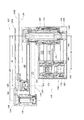
図1Aは、本発明の実施形態による、電子デバイス処理システム100の例示的な実施形態の概略図である。電子デバイス処理システム100は、移送チャンバ102を画定する壁面を有するハウジング101を含みうる。本発明の別の実施形態による多軸ロボット装置103は、移送チャンバ102の内部に少なくとも部分的に収納されうる。多軸ロボットの追加的な図が、図1Bから図1Dに示されている。多軸ロボット装置103は、多軸ロボット装置103の動作を介して、目標位置に基板(例えば基板105A、105B)を載置するか、又は、目標位置から基板を取り出すよう適合しうるが、それについては本書の下記で十分に説明する。
FIG. 1A is a schematic diagram of an exemplary embodiment of an electronic
目標位置は、移送チャンバ102に連結されている、様々な処理チャンバ(例えば、処理チャンバ106A、106B、106C、106D、106E、106F)でありうる。任意には、目標位置は、移送チャンバ102に連結されうる一又は複数のロードロックチャンバ108でありうる。処理チャンバ106Aから106Fは、堆積、酸化、窒化、エッチング、研磨、洗浄、リソグラフィなどの、任意の数の処理ステップを実行するよう適合しうる。他の処理がそれらの中で実行されることもある。ロードロックチャンバ108は、ファクトリインターフェース110の負荷ポートにドッキングされた基板キャリア112から一又は複数の基板を受容しうる、ファクトリインターフェース110と相接するよう適合しうる。基板は、ファクトリインターフェース110内のロボット113(点線で示す)によって移送され、かつ、移送は、矢印114によって示されるように任意の順序又は方向で行われうる。本書で使用する際、基板とは、シリカ含有ウエハ、ガラスプレート、ガラスパネル、マスクなどといった電子デバイス又は回路部品を作るために使用される、物品を意味するものとする。
The target location may be various processing chambers (eg,
ツインチャンバ(例えば、平行面を有する並列チャンバ)の構成が、図1Aに示されており、ロボット装置103は、特に、かかるチャンバであって、移送チャンバ102の中心からオフセットされ、移送チャンバの中心から径方向に延在する線から斜めにオフセットされ、かつ/又は、ロボット103の肩軸からオフセットされている進入方向を有するチャンバに、機能提供することに適している。例えば、ベクトル107は、処理チャンバ106A内への通常の進入の(例えば面に対して垂直な)方向を示し、かつ、ベクトル107が、この実施形態では、移送チャンバ102の中心から、及びロボット装置の肩軸からも、距離dだけ横方向にオフセットされていることを示している。しかし、本書で説明する多軸ロボット103は、図2Aにある4個の処理チャンバと2個のロードロックチャンバとを有する電子デバイス処理システム200Aの、及び、図2Bに示すような、6個の処理チャンバと2個のロードロックチャンバとを有する図2Bの電子デバイス処理システム200Bのメインフレーム構成のような、種々のメインフレーム構成を有する他のツール内の基板の移送において使用するための、ユーティリティを有することを、認識されたい。これらの2つの実施形態の各々では、面は径方向に配向され、その配向において、どの面に対して垂直なベクトルも、ロボットの肩軸及び移送チャンバの中心を通るよう方向付けられる。これらの実施形態におけるロボット103の使用により、任意の数の事前位置付け動作を行うことが可能になる。これは、第1基板がなくなったチャンバ内に第2エンドエフェクタ上に位置付けられた第2基板が置かれる(例えば載置される)時に、あるチャンバから除去された第1エンドエフェクタ上の第1基板が、別のチャンバの隣に事前位置付けされることを可能にする。これらの事前位置付け動作は、スループットを増大させる。
The configuration of a twin chamber (eg, a parallel chamber having parallel surfaces) is shown in FIG. 1A, and the
図1Aを再度参照するに、いくつかの実施形態では、移送チャンバ102は、例えば真空下で操作されうる。処理チャンバ106Aから106F、及び/又は、一又は複数のロードロックチャンバ108に基板105Aから105Bを載置する、及び、それらのチャンバから基板を取り出す時に、処理チャンバ106Aから106F、及び一又は複数のロードロックチャンバ108の各々は、それらの入口/出口に、開閉するよう適合しうるスリットバルブ109を含みうる。スリットバルブ109は、任意の適切な従来型の構造のものでありうる。
Referring again to FIG. 1A, in some embodiments, the
多軸ロボット装置103の様々な構成要素の動作は、コントローラ115からの、多軸ロボット装置103の複数の駆動モータを包含する駆動アセンブリ111に対する、適切なコマンドによって制御されうる。コントローラ115からの信号は、後述から明らかになるように、多軸ロボット装置103の様々な構成要素の動作を引き起こしうる。適切なフィードバックが、位置エンコーダなどのような様々なセンサによって、各構成要素に提供されうる。
The operation of the various components of the multi-axis
ここで図1Aから図1Dを参照するに、多軸ロボット装置103は、一次軸116の周囲で回転可能なブーム104を含む。多軸ロボット装置103は、ハウジング101の壁面(例えばフロア部)に取り付けられるよう適合しているベース117を含みうる。しかし、多軸ロボット装置103は、いくつかの実施形態では、ハウジング101の天井部に取り付けられうる。そのため、多軸ロボット装置103は、ハウジング101によって少なくとも部分的に支持されうる。多軸ロボット装置103は、以下で説明するブーム104、及び様々なアームを駆動するよう構成され、適合している、駆動アセンブリ111も含む。ブーム104は、時計回り又は反時計回りのいずれかの回転方向で、第1回転軸116の周囲で回転するよう適合しうる。本書の下記で更に説明する、従来型の可変リラクタンス電動モータ又は永久磁石電動モータといった任意の適切な電動モータによって、回転が提供されうる。ブーム104の回転は、コントローラ115からの、駆動モータに対する適切なコマンドによって制御されうる。ブーム104は、第1回転軸116の周囲で、ベース117に対してX−Y平面において回転するよう適合している。
Referring now to FIGS. 1A through 1D, the multi-axis
図示されている実施形態では、ロボット装置103は、第1回転軸116から離間した、ブーム104の径方向の外側末端部でブーム104に結合されうる、第1前腕部118及び第2前腕部120を含む。図示されている実施形態では、第1と第2の前腕部118、120は、各々、同一の外側末端位置でブーム104の第1外側末端部に装着され、かつ、第2回転軸122の周囲で共通に回転可能である。図示するように、第2前腕部120は第1前腕部118よりも短い。第1と第2の前腕部118、120の各々は、ブーム104に対して個別に回転可能である。回転は、おおよそ+/−150度でありうる。図示されている実施形態では、第2回転軸122は、約348cmから約522cmまでの距離d1だけ、第1回転軸116から離間しうる(図1D参照)。d1はブーム104の中心間長さである。
In the illustrated embodiment, the
また更に、第1リスト部材124は、第1前腕部118上の第1外側位置に結合されることが可能であり、かつ、第1リスト軸126の周囲で、第1前腕部118に対して個別に回転可能である。第1リスト軸126は、約670cmから約1004cmまでの距離d2だけ、第2回転軸122から離間しうる(図1D参照)。d2は第1前腕部118の第1中心間長さである。第1リスト部材124は、それに結合された第1エンドエフェクタ128を有しうる。第1エンドエフェクタ128は、基板処理システム100の内部で処理されるべき基板105Aを担持するよう適合している。回転は、おおよそ+/−150度でありうる。
Still further, the
第2リスト部材130は、第2前腕部120上の第2外側位置に結合され、かつ、第2リスト軸132の周囲で回転可能でありうる。第2リスト軸132は、約514cmから約772cmまでの距離d3だけ、第2回転軸122から離間しうる(図1D参照)。d3は第2前腕部120の第2中心間長さである。第2中心間長さd3は、いくつかの実施形態では、第1中心間長さd2の90%を下回り、第1中心間長さd2の約50%から約90%でありうる。いくつかの実施形態では、ブーム104の中心間長さd1は、第1前腕部118の第1中心間長さd2よりも短い。いくつかの実施形態では、ブーム104の中心間長さd1は、第2前腕部120の第2中心間長さd3よりも短い。
The
第2リスト部材130は、それに結合された第2エンドエフェクタ134を有しうる。第2エンドエフェクタ134は、基板処理システム100の内部で処理されるべき基板105Bを担持するよう適合している。第2リスト部材130は、第2前腕部120に対して個別に回転可能である。回転は、おおよそ+/−150度でありうる。図1Bからわかるように、第2前腕部120と第2リスト部材130と第2エンドエフェクタ128は、それらが垂直方向に離間するように構成される。具体的には、リストスペーサ135は、第1リスト部材124から垂直方向に第1前腕部118を離間させ、かつ、それと協働して、第2前腕部120の長さが短いことにより、第2前腕部120、第2リスト部材130及び取り付けられた第2エンドエフェクタ134が、第1前腕部118と第1リスト部材124との間を通過すること、及び、リスト継手に干渉することなくリストスペーサ135を通り過ぎることを、可能にする。
The
この特徴をブーム104の個別的な回転性能と結合することで、第1と第2の前腕部118、120の各々、及び、第1と第2のリスト部材124、130の各々は、基板105A、105Bの任意の所望の動作経路の実行において、多大なフレキシビリティを提供する。
By combining this feature with the individual rotational performance of the
図1Aに示す実施形態では、ロボット装置103は、移送チャンバ102内に配置され、収納されて図示されている。しかし、ロボット装置103のこの実施形態、並びに、本書で説明する他のロボット装置は、ロボット装置が、例えば、負荷ポートと処理システム100の一又は複数のロードロックチャンバ108との間で、基板を、又は基板キャリア112までも搬送しうる、ファクトリインターフェース110内のような、電子デバイス製造の他の領域においても使用されうることを、認識されたい。
In the embodiment shown in FIG. 1A, the
ブーム104、第1と第2の前腕部118、120、及び第1と第2のリスト部材124、130の各々の個別的な回転を実現するための駆動アセンブリ111を、以下で詳細に説明する。駆動アセンブリ111は、図1Eに最もよく示されるように、様々な駆動モータ構成要素を包含するよう適合した、モータハウジング136を含む。まず、駆動アセンブリ111は、第1回転軸116の周囲でブーム104を個別に回転させるよう適合した、駆動構成要素を含みうる。回転は、おおよそ+/−360度かそれ以上でありうる。第1駆動シャフト138は、ブーム104から延在し、かつ、適切な軸受によって支持されうる。第1駆動シャフト138は、第1駆動モータ140によって回転されるよう適合している。第1駆動モータ140は、例えば第1ロータと第1ステータとを含む、電動モータでありうる。第1ロータは磁石であり、かつ、第1駆動シャフト138に結合されうる。第1ステータは、上部隔壁142及び下部隔壁143に固定されるか、又は、それらの間で支持されうる。適切な従来型の回転エンコーダ(図示せず)が、ブーム104を所望に応じて位置付けるために使用されうる。
The
更に、駆動アセンブリ111は、ブーム104の外側末端部に配置された第2回転軸122の周囲で第1前腕部118を個別に回転させるよう適合した、駆動構成要素を含みうる。回転は、いくつかの実施形態では、おおよそ+/−150度でありうる。駆動構成要素は、第2駆動シャフト144と第2駆動モータ146とを含みうる。第2駆動モータ146の回転は、第2駆動シャフト144の回転を引き起こし、かつ、結合された第1前腕部118を、第2回転軸122の周囲で駆動する。第2駆動モータ146は、第2ロータと第2ステータとを含む電動モータでありうる。第2駆動シャフト144は、本書で説明するブーム駆動システム148(図1D)から延在し、かつ、適切な軸受によって支持されうる。コントローラ115からの駆動信号を介して第2駆動モータ146を駆動することは、ブーム104に対して、第1前腕部118の個別的な回転を引き起こす。適切な従来型の回転エンコーダ(図示せず)が、第1前腕部118を、所望に応じてブーム104に対して位置付けるために使用されうる。第2ステータは、下部隔壁143に固定されるか、又は、それによって支持されうる。上部と下部の隔壁142、143は、モータハウジング136に固定されるか、又はその一部でありうる。
In addition, the
駆動アセンブリ111は、第1前腕部118上の外側位置に配置された第1リスト軸126の周囲で第1リスト部材124を個別に回転させるよう適合した、駆動構成要素も含みうる。回転は、いくつかの実施形態では、おおよそ+/−150度でありうる。駆動構成要素は、第3駆動シャフト150と第3駆動モータ152とを含みうる。第3駆動モータ152の回転は、第3駆動シャフト150の回転を引き起こし、かつ、結合された第1リスト部材124を、第1リスト軸126の周囲で駆動する。第3駆動モータ152は、第3ロータと第3ステータとを含む電動モータでありうる。第3駆動シャフト150は、ブーム駆動システム148(図1D)から延在し、かつ、適切な軸受によって支持されうる。第3モータ152は、第1前腕部118に対して、第1リスト軸126の周囲で第1リスト部材124の個別的な回転を引き起こすために、コントローラ115からの駆動信号を介して駆動されうる。適切な従来型の回転エンコーダ(図示せず)が、第1リスト部材124を、所望に応じて第1前腕部118に対して位置付けるために使用されうる。第3ステータは、下部隔壁143に固定されるか、又は、それによって支持されうる。
The
また更に、駆動アセンブリ111は、ブーム104の外側末端部に配置された第2回転軸122の周囲で第2前腕部120を個別に回転させるよう適合した、駆動構成要素を含みうる。回転は、いくつかの実施形態では、おおよそ+/−150度でありうる。駆動構成要素は、第4駆動シャフト158と第4駆動モータ160とを含みうる。第4駆動モータ160の回転は、第4駆動シャフト158の回転を引き起こし、かつ、結合された第2前腕部120を、第2回転軸122の周囲で駆動する。第4駆動モータ160は、第4ロータと第4ステータとを含む電動モータでありうる。第4駆動シャフト158は、ブーム駆動システム148(図1D)から延在し、かつ、適切な軸受によって支持されうる。コントローラ115からの駆動信号を介して第4駆動モータ160を駆動することは、ブーム104に対して、第2回転軸122の周囲で第2前腕部120の個別的な回転を引き起こす。適切な従来型の回転エンコーダ(図示せず)が、第2前腕部120を、所望に応じてブーム104に対して位置付けるために使用されうる。第4ステータは、上部隔壁142に固定されるか、又は、それによって支持されうる。
Still further, the
駆動アセンブリ111は、第2前腕部120上の外側位置に配置された第2リスト軸132の周囲で第2リスト部材130を個別に回転させるよう適合した、駆動構成要素も含みうる。回転は、いくつかの実施形態では、おおよそ+/−150度でありうる。駆動構成要素は、第5駆動シャフト154と第5駆動モータ156とを含みうる。第5駆動モータ156の回転は、第5駆動シャフト154の回転を引き起こし、かつ、結合された第2リスト部材130を、第2リスト軸132の周囲で駆動する。第5駆動モータ156は、第5ロータと第5ステータとを含む電動モータでありうる。第5駆動シャフト154は、ブーム駆動システム148(図1D)から延在し、かつ、適切な軸受によって支持されうる。第5駆動モータ156は、第2前腕部120に対して、第2リスト部材130の個別的な回転を引き起こすために、コントローラ115からの駆動信号を介して駆動されうる。適切な従来型の回転エンコーダ(図示せず)が、第2リスト部材130を、所望に応じて第2前腕部120に対して位置付けるために使用されうる。第5ステータは、上部隔壁142に固定されるか、又は、それによって支持されうる。
The
加えて、駆動アセンブリ111はZ軸動作性能を含みうる。具体的には、モータハウジング136は、動作制限装置162によって、外部筐体161に対して回転が制限されうる。動作制限装置162は、2つ以上のリニア軸受、又は、外部筐体161に対してモータハウジング136の回転を制約するよう機能するが、(第1回転軸116の方向に沿った)モータハウジング136のZ軸動作を可能にする、他の軸受又は摺動機構でありうる。垂直モータ163によって垂直動作が提供される。垂直モータ163の回転は、モータハウジング136に結合された、又はそれと一体化したネジ受け163R内で、親ネジ163Sを回転させるよう作動しうる。これは、モータハウジング136を、ゆえに、接続されたブーム104、前腕部118、120、リスト部材124、130、エンドエフェクタ128、134、及び、ひいては基板105A、105Bを、垂直方向に直動させる。適切な密封164が、モータハウジング136とベース117との間を密封し、それによって、垂直動作に適応し、かつ、チャンバ102の内部で真空を維持しうる。金属製ベローズ又は他の類似のフレキシブルな密封が、密封164のために使用されうる。駆動アセンブリ811の代替的な実施形態が、図8に示される。
In addition, the
ここで図1Dを参照して、例示的なブーム駆動システム148を詳細に説明する。ブーム駆動システム148は、上述の様々な駆動シャフトを、第1前腕部118、第2前腕部120、第1リスト部材124、及び第2リスト部材130に結合するよう構成され、適合しているプーリ及びベルトのような、駆動構成要素を含みうる。駆動構成要素は、第2駆動シャフト144に結合されている第1前腕部駆動部材165、第1前腕部118に結合されている第1前腕部従動部材168、及び、第1前腕部駆動部材165と第1前腕部従動部材168との間に結合された第1前腕部伝達部材170を含みうる。第2駆動シャフト144の回転は、従って、第1前腕部118を回転させる。第1前腕部駆動部材165と第1前腕部従動部材168の各々は、軸受によって、ブーム104の硬性ウェブ部分171に装着されうる。
With reference now to FIG. 1D, an exemplary
ブーム駆動システム148は、第1リスト駆動部材172と第1リスト従動部材174とを含みうる。第1リスト駆動部材172は第3駆動シャフト150に結合され、かつ、第1リスト従動部材174は第1リスト部材124に結合される。第1リスト伝達部材173は、ウェブ部分171の上方で、第1リスト駆動部材172を第1リスト従動部材174に結合する。第1前腕部118を通じて第1リスト従動部材174を第1リスト部材124に結合する、第1中間伝達部材175によって、第1リスト部材124への結合が提供される。第1リスト伝達部材175は、リストスペーサ135の下方で第1リスト部材124に結合されうる。第1リスト部材124は、リストスペーサ135内に装着された軸受を介して、第1リスト軸126の周囲で回転可能でありうる。リストスペーサ135は、第1エンドエフェクタ128を、第2エンドエフェクタ134の上方に適切に離間させるよう機能する。
The
再度図1Dを参照するに、ブーム駆動システム148は、第2前腕部120を駆動するよう適合しているプーリ及びベルトのような、駆動構成要素を含みうる。駆動構成要素は、第4駆動シャフト158に結合されている第2前腕部駆動部材176、第2前腕部120に結合されている第2前腕部従動部材178、及び、第2前腕部駆動部材176と第2前腕部従動部材178の間に結合された第2前腕部伝達部材180を含みうる。第4駆動シャフト158の回転は、従って、第2前腕部120を回転させる。第2前腕部駆動部材176と第2前腕部従動部材178の各々は、軸受によって、ブーム104の硬性ウェブ部分171に装着されうる。
Referring again to FIG. 1D, the
ブーム駆動システム148は、第2リスト駆動部材182と第2リスト従動部材184とを含みうる。第2リスト駆動部材182は第5駆動シャフト154に結合され、かつ、第2リスト従動部材184は第2リスト部材130に結合される。第2リスト伝達部材186は、ウェブ部分171の下方で、第2リスト駆動部材182を第2リスト従動部材184に結合する。第2前腕部120を通じて第2リスト従動部材184を第2リスト部材130に結合する、第2中間伝達部材188によって、第2リスト部材130への結合が提供される。第2リスト部材130は、第2前腕部120の外側端部位置に装着された軸受を介して、第2リスト軸132の周囲で回転可能でありうる。ブーム駆動システム703の代替的な一実施形態を図7に示す。
The
図3Aから図3Bは、電子デバイス処理システム100の内部で使用するよう適合しうる実施形態による、別のロボット装置303を示す。ロボット装置303の一例を図3Aに示すが、ここでロボット装置303は、基板305Aを担持している第1エンドエフェクタ328を、チャンバ(図示せず)内に挿入すると共に、第2基板305Bを担持している第2エンドエフェクタ334が別のチャンバに隣接して事前位置付けされるよう適合した一構成において示されている、個別に回転可能なブーム304、個別に回転可能な第1と第2の前腕部318、320、及び、個別に回転可能な第1と第2のリスト部材324、330を含みうる。
3A-3B illustrate another
図3Bは、折畳まれた状態のロボット装置303を示す。折畳まれた状態では、システムは、同時に搬送されている基板305A、305Bが、互いの直上に位置する、又は、互いの直上を通過することがないように構成されうることに、留意されたい。換言すると、一方の基板(例えば基板305A)が他方の基板(例えば基板305B)の上方にない(又は上方を通過しない)ように、前腕部318、320、リスト部材324、330、及びエンドエフェクタ328、334が、垂直方向に位置合わせされている時に、両基板の中心は、水平方向に十分にオフセットされうる。これは、下方の基板305Aの粒子汚染を低減しうる。しかし、他の構成も可能である。
FIG. 3B shows the
図3Cは、折畳まれた状態のロボット装置303を示す。ロボット装置303は、駆動モータ140、146、152、156及び160(図1E)のような駆動モータを包含するモータハウジング336、及び、外部筐体361を有する、駆動アセンブリ311を含む。ブーム304及び接続した構成要素、ひいては、基板305A、305Bを上昇させる、垂直Z軸性能が提供される。動作中に、モータハウジング336は、一又は複数の動作制限装置362A、362Bによって、外部筐体361に対して回転が制限されうる。動作制限装置362A、362Bは、キャリッジ367に結合された、垂直に配向された2つ以上の線形摺動機構でありうる。キャリッジ367は、モータハウジングに固定されるか、それと一体化される。動作制限装置362A、362Bは、外部筐体361に対してモータハウジング336の回転を制約するよう機能するが、モータハウジング336のZ軸動作を可能にする。外部筐体361に結合された垂直モータ363によって、垂直動作が提供される。垂直モータ363の回転は、キャリッジ367又はモータハウジング336に結合された、又は、それと一体化したネジ受け363R内で、親ネジ363Sを回転させる。これは、モータハウジング336、ゆえに、接続されたブーム304、前腕部318、320、リスト部材324、330、エンドエフェクタ328、334、及び、ひいては基板305A、305Bを、垂直方向に直動させる。適切な密封364が、モータハウジング336とベース317との間を密封し、それによって、垂直動作に適応し、かつ、ロボット303が中で作動するチャンバ102の内部で真空を維持しうる。金属製ベローズ又は他の類似のフレキシブルな密封が、密封364のために使用されうる。
FIG. 3C shows the
図4は、電子デバイス処理システム100の内部で使用するよう適合しうる実施形態による、別のロボット装置403を示す。ロボット装置403は、エンドエフェクタ428、434及びリスト部材424、430という異なる構成を含むが、それ以外は図1Bから図1Eの実施形態において説明された通りである。
FIG. 4 illustrates another
ここで図5を参照するに、図1Bから図1Eのロボット装置を含む、別のシステム500が提供されている。動作中に、ブーム104は、まず第1回転軸の周囲で回転して、ブーム104の外側末端部を、第1目標位置、すなわち、ロボット装置103が目標位置に容易にアクセスしうる位置にある目標位置に、隣接して載置しうる。ロボット装置103は次いで、起動して、一方のエンドエフェクタで目標位置(例えば処理チャンバ506C)から基板105Aを取り上げ、続いて、ロボット装置103の他方のエンドエフェクタで、その目標位置(例えば処理チャンバ506C)に別の基板105Bを載置し、ゆえに、交換を実行しうる。第1基板が除去される際に、基板105Aが第2目標位置(例えば処理チャンバ506B)の隣に載置されるように、前腕部とリスト部材は、直ちに移動し、ゆえに、事前位置付け動作を実行しうる。この第2目標位置において、ロボット装置103は、処理チャンバ506Cについての説明と同一の様態で、エンドエフェクタで別の完成品基板の交換を実行しうる。他の実施形態では、前腕部とリスト部材は、直ちに移動し、ゆえに、基板105Aを、例えばロードロックチャンバ508A又は508Bへと直接的に移動させ、その中に基板105Aを直接的に載置しうる。そのため、面が平行した処理チャンバの対(例えば506Aと506B、506Cと506D、及び506Eと506F)、並びに、面が平行したロードロックチャンバの対(例えば508Aと506B)は、ロボット装置103によって機能提供されることが可能であり、一方の前腕部(例えば前腕部120)が他方の前腕部(例えば118)よりも短い状態で、個別に動作可能なブーム104、個別に動作可能な前腕部118、120、及び、個別に動作可能なリスト部材124、130を組み合わせることにより、交換がより効率的に実行されうる。
Referring now to FIG. 5, another
本発明の実施形態による、電子デバイス処理システム(例えば100、200A、200B、500)の内部で基板(例えば105A、105B)を搬送する方法600が、図6で提供される。方法600は、第1回転軸(例えば第1回転軸116)の周囲で回転するよう適合したブーム(例えばブーム104)を提供すること(602)を含む。ブーム104は中心間長さd1を有しうる。方法600は、ブームの外側末端部でブームに回転式に結合された第1前腕部(例えば第1前腕部118)を提供すること(604)を含む。外側末端部は、第1回転軸116から離間している。方法600は、ブームの外側末端部でブームに回転式に結合された第2前腕部(例えば第2前腕部120)を提供すること(606)を含み、第2前腕部は第1前腕部よりも短い。その長さは、第2前腕部120が、第リスト1部材(例えば第1リスト部材124)を第1前腕部(例えば第1前腕部118)に接続するリスト継手の付近を通過しうるように、十分に短くあるべきである。方法600は、第1前腕部の外側位置で第1前腕部に回転式に結合された第1リスト部材を提供すること(608)と、第2前腕部の外側位置で第2前腕部に回転式に結合された第2リスト部材(例えば第2リスト部材130)を提供すること(610)とを含む。602から610までの各々は、様々な構成要素が組み立てられる組立作業によって完遂されうる。方法600は任意の順番で実行されうる。方法600は更に、基板(例えば基板105A、105B)をチャンバからチャンバへと搬送するために、第1前腕部、第2前腕部、第1リスト部材及び第2リスト部材を個別に回転させ、かつ、搬送における少なくともいずれかの時点に、第2前腕部を第1前腕部の上で移動させること(612)を含む。第2前腕部が短いこと、及び、リスト継手との間に間隙(例えばスペーサ135との間の間隙)があることによる、第2前腕部(例えば第2前腕部120)の第1前腕部(例えば第1前腕部118)の上での移動が、迅速かつ多様な動作経路性能を可能にする。
A
別の態様では、除去された基板(例えば基板105A)の、別のチャンバ(例えば処理チャンバ又はロードロックチャンバ)に隣接した事前位置付けが、実現されうる。例えば、第2基板(例えば105B)が第1チャンバ(例えば506C)内に載置されると共に、第2チャンバ(例えばチャンバ506B)に隣接した位置に、第1チャンバから従前に除去された第1基板(例えば105A)を事前位置付けしうる。別の態様では、チャンバ(例えばチャンバ506C)は、たとえチャンバ506Cが、第1回転軸(例えば第1回転軸516−図5)からオフセット距離590だけ軸方向にオフセットされていても、機能提供されうる。この様態では、基板(例えば基板105B)は、たとえ進入線が第1回転軸と位置合わせされていなくても、面に垂直にチャンバ506C内に挿入されることが可能である。これは、機能提供されるべき複数の処理チャンバを各側部に有する、長方形又は正方形の移送チャンバ(例えば移送チャンバ502)を可能にする。別の態様では、チャンバ(例えば105B)における第1基板(例えば105A)と第2基板(例えば105B)の交換が、交換動作プロファイルにおいて、第2基板105Bが第1基板105Aの垂直方向に下方に位置付けられることは決してないように、第1前腕部118、第1リスト部材124、第2前腕部120、及び第2リスト部材130を個別に回転させることによる様態で、実行されることが可能である。これにより、第2基板105Bの汚染を回避しうる。
In another aspect, prepositioning of the removed substrate (eg,
前述の説明は、本発明の単なる例示的な実施形態を開示している。本発明の範囲内に該当する、上記で開示された装置、システム及び方法の変形例は、当業者には容易に明らかになるだろう。そのため、本発明は例示的な実施形態に関連して開示されているが、他の実施形態も、以下の特許請求の範囲によって定義されるように、本発明の範囲内に該当しうると理解されるべきである。
The foregoing description discloses merely exemplary embodiments of the invention. Variations of the apparatus, systems and methods disclosed above that fall within the scope of the invention will be readily apparent to those skilled in the art. As such, while the invention has been disclosed in connection with exemplary embodiments, it will be understood that other embodiments may fall within the scope of the invention as defined by the following claims. It should be.
Claims (16)
第1回転軸の周囲で回転するよう適合したブームと、
前記ブームの外側末端部で前記ブームに回転式に結合された第1前腕部とを備え、前記第1前腕部は、第2回転軸の周囲で個別に回転するよう構成され、
前記ブームの前記外側末端部で前記ブームに回転式に結合され、かつ、前記第2回転軸の周囲で個別に回転するよう構成された、第2前腕部を備え、前記第2前腕部は前記第1前腕部よりも短く、
前記第1前腕部の第1外側位置で前記第1前腕部に回転式に結合され、かつ、第3の軸の周囲で、前記第1前腕部に対して個別に回転するよう構成された、第1リスト部材と、
第2外側位置で前記第2前腕部に回転式に結合され、かつ、第4の軸の周囲で、前記第2前腕部に対して個別に回転するよう構成された、第2リスト部材とを備える、多軸ロボット。 A multi-axis robot,
A boom adapted to rotate about the first axis of rotation;
A first forearm portion rotatably coupled to the boom at an outer end portion of the boom, wherein the first forearm portion is configured to rotate individually around a second rotation axis;
A second forearm portion rotatably coupled to the boom at the outer end of the boom and configured to individually rotate about the second rotation axis, the second forearm portion being Shorter than the first forearm,
Wherein the first forearm portion is rotationally coupled to the first forearm portion at a first outer position and is configured to individually rotate relative to the first forearm portion about a third axis; A first list member;
A second wrist member rotatably coupled to the second forearm portion at a second outer position and configured to individually rotate relative to the second forearm portion about a fourth axis; A multi-axis robot equipped.
前記第1前腕部に結合された第2駆動モータと、
前記第1リスト部材に結合された第3駆動モータと、
前記第2前腕部に結合された第4駆動モータと、
前記第2リスト部材に結合された第5駆動モータとを更に含む、請求項1に記載の多軸ロボット。 A first drive motor coupled to the boom;
A second drive motor coupled to the first forearm;
A third drive motor coupled to the first wrist member;
A fourth drive motor coupled to the second forearm;
The multi-axis robot according to claim 1, further comprising a fifth drive motor coupled to the second wrist member.
前記第2駆動モータの第2ステータと、
前記第3駆動モータの第3ステータと、
前記第4駆動モータの第4ステータと、
前記第5駆動モータの第5ステータと、
前記第4ステータと前記第5ステータとを支持する上部隔壁と、
前記第2ステータと前記第3ステータとを支持する下部隔壁とを更に含み、かつ、
前記第1ステータは、上部隔壁と下部隔壁との間に受容されている、請求項2に記載の多軸ロボット。 A first stator of the first drive motor;
A second stator of the second drive motor;
A third stator of the third drive motor;
A fourth stator of the fourth drive motor;
A fifth stator of the fifth drive motor;
An upper partition that supports the fourth stator and the fifth stator;
A lower partition wall supporting the second stator and the third stator; and
The multi-axis robot according to claim 2 , wherein the first stator is received between an upper partition wall and a lower partition wall.
前記ブームは、ウェブ部分と、
前記ウェブ部分の上方で、前記ブームに回転式に装着された第1前腕部駆動部材と、
前記ウェブ部分の上方で、前記ブームに回転式に装着された第1リスト駆動部材と、
前記ウェブ部分の上方で、前記ブームに外側末端部で回転式に装着された第1前腕部従動部材と、
前記ウェブ部分の上方で、前記ブームに外側末端部で回転式に装着された第1リスト従動部材と、
前記ウェブ部分の上方で、前記第1前腕部駆動部材を前記第1前腕部従動部材に結合する第1前腕部伝達部材と、
前記ウェブ部分の上方で、前記第1リスト駆動部材を前記第1リスト従動部材に結合する第1リスト伝達部材とを含む、請求項1に記載の多軸ロボット。 Further including a boom drive,
The boom includes a web portion;
A first forearm drive member rotatably mounted on the boom above the web portion;
A first wrist drive member rotatably mounted on the boom above the web portion;
A first forearm driven member rotatably mounted on the boom at an outer end above the web portion;
A first wrist driven member rotatably mounted on the boom at an outer end above the web portion;
A first forearm transmission member that couples the first forearm drive member to the first forearm follower over the web portion;
The multi-axis robot according to claim 1, further comprising a first wrist transmission member that couples the first wrist driving member to the first wrist driven member above the web portion.
前記ウェブ部分の下方で、前記ブームに回転式に装着された第2前腕部駆動部材と、
前記ウェブ部分の下方で、前記ブームに回転式に装着された第2リスト駆動部材と、
前記ウェブ部分の下方で、前記ブームに外側末端部で回転式に装着された第2前腕部従動部材と、
前記ウェブ部分の下方で、前記ブームに外側末端部で回転式に装着された第2リスト従動部材と、
前記ウェブ部分の下方で、前記第2前腕部駆動部材を前記第2前腕部従動部材に結合する第2前腕部伝達部材と、
前記ウェブ部分の下方で、前記第2リスト駆動部材を前記第2リスト従動部材に結合する第2リスト伝達部材とを更に含み、
前記多軸ロボットは、前記第2リスト駆動部材と前記第2リスト部材との間に結合された第2中間伝達部材を更に含む、請求項9に記載の多軸ロボット。 The boom drive device is:
A second forearm drive member rotatably mounted on the boom below the web portion;
A second wrist drive member rotatably mounted on the boom below the web portion;
A second forearm driven member rotatably mounted on the boom at an outer end below the web portion;
Below the web portion, a second wrist follower member rotatably mounted on the boom at the outer end;
A second forearm transmission member that couples the second forearm drive member to the second forearm driven member below the web portion;
A second wrist transmission member that couples the second wrist driving member to the second wrist driven member below the web portion;
The multi-axis robot according to claim 9, wherein the multi-axis robot further includes a second intermediate transmission member coupled between the second wrist driving member and the second wrist member.
移送チャンバと、
前記移送チャンバ内に少なくとも部分的に受容されたマルチリンクロボット装置とを備え、前記マルチリンクロボット装置は、
第1回転軸の周囲で回転するよう適合したブームと、
前記ブームの外側末端部で前記ブームに回転式に結合され、かつ、個別に回転するよう構成された、第1前腕部と、
前記ブームの前記外側末端部で前記ブームに回転式に結合され、かつ、個別に回転するよう構成された、第2前腕部とを有し、前記第2前腕部は前記第1前腕部よりも短く、
前記第1前腕部に回転式に結合され、かつ、前記第1前腕部に対して個別に回転するよう構成された、第1リスト部材と、
前記第2前腕部に回転式に結合され、かつ、前記第2前腕部に対して個別に回転するよう構成された、第2リスト部材とを有する、電子デバイス処理システム。 An electronic device processing system,
A transfer chamber;
A multilink robotic device received at least partially within the transfer chamber, the multilink robotic device comprising:
A boom adapted to rotate about the first axis of rotation;
A first forearm portion rotatably coupled to the boom at an outer end of the boom and configured to rotate individually;
A second forearm portion rotatably coupled to the boom at the outer end portion of the boom and configured to rotate individually, the second forearm portion being more than the first forearm portion. Short,
A first wrist member coupled to the first forearm portion in a rotational manner and configured to individually rotate relative to the first forearm portion;
An electronic device processing system comprising: a second wrist member rotatably coupled to the second forearm portion and configured to rotate individually with respect to the second forearm portion.
第1回転軸の周囲で回転するよう適合したブームを提供することと、
前記ブームの外側末端部で前記ブームに回転式に結合された第1前腕部を提供することと、
前記ブームの前記外側末端部で前記ブームに回転式に結合された第2前腕部を提供することとを含み、前記第2前腕部は前記第1前腕部よりも短く、
前記第1前腕部の外側位置で前記第1前腕部に回転式に結合された第1リスト部材を提供することと、
前記第2前腕部の外側位置で前記第2前腕部に回転式に結合された第2リスト部材を提供することと、
基板をチャンバからチャンバへと搬送するために、前記第1前腕部、前記第2前腕部、前記第1リスト部材及び前記第2リスト部材を個別に回転させ、かつ、前記搬送における少なくともいずれかの時点に、前記第2前腕部を前記第1前腕部の上で移動させることを含む、方法。 A method of transporting a substrate inside an electronic device processing system,
Providing a boom adapted to rotate about a first axis of rotation;
Providing a first forearm portion rotationally coupled to the boom at an outer end of the boom;
Providing a second forearm portion rotationally coupled to the boom at the outer end of the boom, wherein the second forearm portion is shorter than the first forearm portion,
Providing a first wrist member rotationally coupled to the first forearm portion at an outer position of the first forearm portion;
Providing a second wrist member rotationally coupled to the second forearm portion at an outer position of the second forearm portion;
In order to transport the substrate from chamber to chamber, the first forearm portion, the second forearm portion, the first wrist member and the second wrist member are individually rotated, and at least one of the transports Moving the second forearm over the first forearm at a point in time.
前記第1前腕部に結合された第2駆動シャフトに結合された第2駆動モータの第2ステータと、A second stator of a second drive motor coupled to a second drive shaft coupled to the first forearm;
前記第1リスト部材に結合された第3駆動シャフトに結合された第3駆動モータの第3ステータと、A third stator of a third drive motor coupled to a third drive shaft coupled to the first wrist member;
前記第2前腕部に結合された第4駆動シャフトに結合された第4駆動モータの第4ステータと、A fourth stator of a fourth drive motor coupled to a fourth drive shaft coupled to the second forearm;
前記第2リスト部材に結合された第5駆動シャフトに結合された第5駆動モータの第5ステータと、A fifth stator of a fifth drive motor coupled to a fifth drive shaft coupled to the second wrist member;
前記第4ステータと前記第5ステータとを支持する上部隔壁と、An upper partition that supports the fourth stator and the fifth stator;
前記第2ステータと前記第3ステータとを支持する下部隔壁とを更に含み、かつ、A lower partition wall supporting the second stator and the third stator; and
前記第1ステータは、上部隔壁と下部隔壁との間に受容されている、請求項1に記載の多軸ロボット。The multi-axis robot according to claim 1, wherein the first stator is received between an upper partition wall and a lower partition wall.
Applications Claiming Priority (3)
| Application Number | Priority Date | Filing Date | Title |
|---|---|---|---|
| US201261732196P | 2012-11-30 | 2012-11-30 | |
| US61/732,196 | 2012-11-30 | ||
| PCT/US2013/072048 WO2014085479A1 (en) | 2012-11-30 | 2013-11-26 | Multi-axis robot apparatus with unequal length forearms, electronic device manufacturing systems, and methods for transporting substrates in electronic device manufacturing |
Publications (3)
| Publication Number | Publication Date |
|---|---|
| JP2016500473A JP2016500473A (en) | 2016-01-12 |
| JP2016500473A5 JP2016500473A5 (en) | 2017-01-12 |
| JP6336467B2 true JP6336467B2 (en) | 2018-06-06 |
Family
ID=50824133
Family Applications (2)
| Application Number | Title | Priority Date | Filing Date |
|---|---|---|---|
| JP2015545190A Active JP6336467B2 (en) | 2012-11-30 | 2013-11-26 | Multi-axis robot apparatus having unequal length forearm, electronic device manufacturing system, and method for transporting substrate in electronic device manufacturing |
| JP2015545192A Active JP6382213B2 (en) | 2012-11-30 | 2013-11-26 | Motor module, multi-axis motor drive assembly, multi-axis robot apparatus, and electronic device manufacturing system and method |
Family Applications After (1)
| Application Number | Title | Priority Date | Filing Date |
|---|---|---|---|
| JP2015545192A Active JP6382213B2 (en) | 2012-11-30 | 2013-11-26 | Motor module, multi-axis motor drive assembly, multi-axis robot apparatus, and electronic device manufacturing system and method |
Country Status (6)
| Country | Link |
|---|---|
| US (2) | US9325228B2 (en) |
| JP (2) | JP6336467B2 (en) |
| KR (3) | KR102214398B1 (en) |
| CN (2) | CN104823272B (en) |
| TW (2) | TWI609557B (en) |
| WO (2) | WO2014085483A1 (en) |
Families Citing this family (69)
| Publication number | Priority date | Publication date | Assignee | Title |
|---|---|---|---|---|
| US10086511B2 (en) * | 2003-11-10 | 2018-10-02 | Brooks Automation, Inc. | Semiconductor manufacturing systems |
| USD723239S1 (en) * | 2012-08-30 | 2015-02-24 | Entegris, Inc. | Wafer carrier ring |
| US9190306B2 (en) * | 2012-11-30 | 2015-11-17 | Lam Research Corporation | Dual arm vacuum robot |
| US9149936B2 (en) | 2013-01-18 | 2015-10-06 | Persimmon Technologies, Corp. | Robot having arm with unequal link lengths |
| US10224232B2 (en) | 2013-01-18 | 2019-03-05 | Persimmon Technologies Corporation | Robot having two arms with unequal link lengths |
| CN103192384B (en) * | 2013-03-11 | 2015-08-19 | 上海交通大学 | A kind of permanent vacuum axle system device of integrated rotary transformer |
| US10427303B2 (en) * | 2013-03-15 | 2019-10-01 | Applied Materials, Inc. | Substrate deposition systems, robot transfer apparatus, and methods for electronic device manufacturing |
| WO2014152380A1 (en) * | 2013-03-15 | 2014-09-25 | Electro Scientific Industries, Inc. | Laser systems and methods for aod rout processing |
| JP6337432B2 (en) | 2013-09-10 | 2018-06-06 | セイコーエプソン株式会社 | Joint drive device and robot |
| US9796097B2 (en) * | 2013-09-10 | 2017-10-24 | Seiko Epson Corporation | Robot and manufacturing method for robot |
| WO2015059520A1 (en) | 2013-10-23 | 2015-04-30 | Prysmian S.P.A. | Energy cable having a crosslinked electrically insulating layer, and method for extracting crosslinking by-products therefrom |
| JP6679482B2 (en) | 2013-11-13 | 2020-04-15 | ブルックス オートメーション インコーポレイテッド | Control method and apparatus for brushless electric machine |
| WO2015073647A1 (en) | 2013-11-13 | 2015-05-21 | Brooks Automation, Inc. | Sealed robot drive |
| WO2015073658A1 (en) | 2013-11-13 | 2015-05-21 | Brooks Automation, Inc. | Sealed switched reluctance motor |
| TWI695447B (en) | 2013-11-13 | 2020-06-01 | 布魯克斯自動機械公司 | Transport apparatus |
| JP6550391B2 (en) | 2014-01-05 | 2019-07-24 | アプライド マテリアルズ インコーポレイテッドApplied Materials,Incorporated | Robotic apparatus, drive assembly and method for transferring a substrate in electronic device manufacturing |
| JP6474971B2 (en) * | 2014-07-03 | 2019-02-27 | 株式会社ダイヘン | Work transfer device |
| DE102014009892B4 (en) * | 2014-07-04 | 2018-05-30 | gomtec GmbH | Drive unit with magnetic interface |
| JP7079604B2 (en) * | 2015-02-06 | 2022-06-02 | パーシモン テクノロジーズ コーポレイション | Robot with an arm with unequal link length |
| USD767234S1 (en) * | 2015-03-02 | 2016-09-20 | Entegris, Inc. | Wafer support ring |
| CN114367970B (en) | 2015-03-12 | 2024-04-05 | 柿子技术公司 | Robot with driven end effector motion |
| KR102557355B1 (en) * | 2015-07-13 | 2023-07-20 | 브룩스 오토메이션 인코퍼레이티드 | substrate transport device |
| US10134623B2 (en) | 2015-07-13 | 2018-11-20 | Brooks Automation, Inc. | On the fly automatic wafer centering method and apparatus |
| CN105108387A (en) * | 2015-08-31 | 2015-12-02 | 苏州斯尔特微电子有限公司 | Turning arm on electronic welding machine |
| US9799544B2 (en) | 2015-10-23 | 2017-10-24 | Applied Materials, Inc. | Robot assemblies, substrate processing apparatus, and methods for transporting substrates in electronic device manufacturing |
| CN105391210B (en) * | 2015-12-28 | 2017-11-21 | 苏州大学 | Inner rotor motor |
| CN105702607B (en) * | 2016-03-17 | 2018-09-25 | 东方晶源微电子科技(北京)有限公司 | Mechanical arm and inspection system |
| CN106003134B (en) * | 2016-05-26 | 2020-09-29 | 中国科学院等离子体物理研究所 | Rotary joint used in vacuum high-temperature environment |
| CN106003027B (en) * | 2016-06-03 | 2019-03-01 | 广州视源电子科技股份有限公司 | The setting method and system in manipulator motion path |
| TWI707754B (en) | 2016-06-28 | 2020-10-21 | 美商應用材料股份有限公司 | Dual robot including spaced upper arms and interleaved wrists and systems and methods including same |
| CN106041919A (en) * | 2016-07-11 | 2016-10-26 | 深圳众为兴技术股份有限公司 | Lifting type robot structure |
| TWI813555B (en) * | 2017-02-07 | 2023-09-01 | 美商布魯克斯自動機械美國公司 | Method and apparatus for substrate transport |
| US20180308728A1 (en) * | 2017-02-07 | 2018-10-25 | Brooks Automation, Inc. | Method and apparatus for substrate transport |
| US10312770B2 (en) * | 2017-02-25 | 2019-06-04 | Applied Motion Products, Inc. | Motor with integrated connector enclosure |
| JP6862233B2 (en) * | 2017-03-27 | 2021-04-21 | 日本電産サンキョー株式会社 | Industrial robot |
| CN107953363B (en) * | 2017-05-10 | 2021-09-07 | Abb瑞士股份有限公司 | Arm for multi-joint robot and multi-joint robot |
| EP3410577A1 (en) * | 2017-06-02 | 2018-12-05 | Siemens Aktiengesellschaft | Cable duct |
| US10629472B2 (en) | 2017-08-17 | 2020-04-21 | Persimmon Technologies Corporation | Material handling robot |
| US10453725B2 (en) | 2017-09-19 | 2019-10-22 | Applied Materials, Inc. | Dual-blade robot including vertically offset horizontally overlapping frog-leg linkages and systems and methods including same |
| JP6873881B2 (en) * | 2017-10-13 | 2021-05-19 | 日本電産サンキョー株式会社 | Industrial robot |
| TWI768849B (en) | 2017-10-27 | 2022-06-21 | 美商應用材料股份有限公司 | Single wafer processing environments with spatial separation |
| JP6962790B2 (en) * | 2017-11-09 | 2021-11-05 | 日本電産サンキョー株式会社 | Work transfer system and its control method |
| US10155309B1 (en) * | 2017-11-16 | 2018-12-18 | Lam Research Corporation | Wafer handling robots with rotational joint encoders |
| KR101983563B1 (en) * | 2017-11-23 | 2019-05-29 | (주)한국미래기술 | Parallel type integrated actuator |
| KR101956617B1 (en) * | 2017-11-23 | 2019-03-12 | (주)한국미래기술 | Parallel type integrated actuator |
| US10943805B2 (en) | 2018-05-18 | 2021-03-09 | Applied Materials, Inc. | Multi-blade robot apparatus, electronic device manufacturing apparatus, and methods adapted to transport multiple substrates in electronic device manufacturing |
| JP7078479B2 (en) * | 2018-07-13 | 2022-05-31 | 株式会社安川電機 | Transport robots and robot systems |
| CN109018783A (en) * | 2018-07-20 | 2018-12-18 | 湖南瑭桥科技发展有限公司 | A kind of novel garbage truck manipulator folding arm directing controller |
| WO2020060715A1 (en) | 2018-09-21 | 2020-03-26 | Applied Materials, Inc. | Portion of layer removal at substrate edge |
| CN112219269A (en) * | 2018-11-19 | 2021-01-12 | 玛特森技术公司 | System and method for machining a workpiece |
| TWM579415U (en) | 2019-03-08 | 2019-06-11 | 華碩電腦股份有限公司 | Function assembly and electronic device including the same |
| JP2022524531A (en) | 2019-03-11 | 2022-05-06 | パーシモン テクノロジーズ コーポレイション | Asymmetric dual end effector robot arm |
| US11850742B2 (en) | 2019-06-07 | 2023-12-26 | Applied Materials, Inc. | Dual robot including splayed end effectors and systems and methods including same |
| KR20220031700A (en) | 2019-07-12 | 2022-03-11 | 어플라이드 머티어리얼스, 인코포레이티드 | Robot for simultaneous board transfer |
| US11117265B2 (en) * | 2019-07-12 | 2021-09-14 | Applied Materials, Inc. | Robot for simultaneous substrate transfer |
| US11574826B2 (en) | 2019-07-12 | 2023-02-07 | Applied Materials, Inc. | High-density substrate processing systems and methods |
| US11443973B2 (en) * | 2019-07-12 | 2022-09-13 | Applied Materials, Inc. | Robot for simultaneous substrate transfer |
| KR20220025899A (en) | 2019-07-12 | 2022-03-03 | 어플라이드 머티어리얼스, 인코포레이티드 | Robot for simultaneous board transfer |
| TWI797461B (en) * | 2019-07-26 | 2023-04-01 | 日商新川股份有限公司 | Packaging device |
| CN111546321A (en) * | 2020-06-15 | 2020-08-18 | 含山县大力精密机械有限公司 | Transverse carrying robot arm suitable for high load and method |
| US20210407837A1 (en) * | 2020-06-30 | 2021-12-30 | Applied Materials, Inc. | Robot apparatus and systems, and methods for transporting substrates in electronic device manufacturing |
| US20220005726A1 (en) * | 2020-07-02 | 2022-01-06 | Applied Materials, Inc. | Robot apparatus, systems, and methods for transporting substrates in electronic device manufacturing |
| US11602064B2 (en) | 2020-09-01 | 2023-03-07 | Applied Materials, Inc. | Dynamic electrical and fluid delivery system with indexing motion for batch processing chambers |
| US20220111513A1 (en) * | 2020-10-14 | 2022-04-14 | Applied Materials, Inc. | Infinite rotation of vacuum robot linkage through timing belt with isolated environment |
| TW202218831A (en) * | 2020-11-06 | 2022-05-16 | 日商發那科股份有限公司 | Horizontal articulated robot |
| CN112563178B (en) * | 2021-02-23 | 2021-06-29 | 宁波群芯微电子有限责任公司 | Chip transfer manipulator |
| TWI782507B (en) * | 2021-04-28 | 2022-11-01 | 富力特科技股份有限公司 | A cassette feeding robot arm and sensor with a thin and brittle substrate rubbing vibration sensor |
| KR102552870B1 (en) * | 2021-10-29 | 2023-07-10 | 주식회사 라온테크 | Wafer transfer robot apparatus based on direct drive motor |
| WO2023102497A1 (en) * | 2021-12-03 | 2023-06-08 | Lam Research Corporation | Direct-pick robot for multi station semiconductor processing chambers |
Family Cites Families (41)
| Publication number | Priority date | Publication date | Assignee | Title |
|---|---|---|---|---|
| JPH03154791A (en) | 1989-11-14 | 1991-07-02 | Sumitomo Eaton Noba Kk | Articulated arm for robot |
| JPH0536809A (en) | 1991-07-31 | 1993-02-12 | Mitsubishi Electric Corp | Semiconductor substrate transfer arm in semiconductor substrate treatment device |
| JPH05109866A (en) * | 1991-10-16 | 1993-04-30 | Nec Corp | Wafer transfer robot |
| US5765444A (en) * | 1995-07-10 | 1998-06-16 | Kensington Laboratories, Inc. | Dual end effector, multiple link robot arm system with corner reacharound and extended reach capabilities |
| US6102164A (en) * | 1996-02-28 | 2000-08-15 | Applied Materials, Inc. | Multiple independent robot assembly and apparatus for processing and transferring semiconductor wafers |
| JP3495903B2 (en) * | 1998-01-30 | 2004-02-09 | 多摩川精機株式会社 | Vacuum motor |
| JP2000069741A (en) * | 1998-08-19 | 2000-03-03 | Komatsu Ltd | Actuator for vacuum |
| US6543306B1 (en) * | 1998-12-04 | 2003-04-08 | Daihen Corporation | Conveying device |
| US6485250B2 (en) * | 1998-12-30 | 2002-11-26 | Brooks Automation Inc. | Substrate transport apparatus with multiple arms on a common axis of rotation |
| JP4445075B2 (en) * | 1999-10-06 | 2010-04-07 | 東京エレクトロン株式会社 | Vacuum motor and transfer device |
| US6601468B2 (en) * | 2000-10-24 | 2003-08-05 | Innovative Robotic Solutions | Drive system for multiple axis robot arm |
| JP2002158272A (en) * | 2000-11-17 | 2002-05-31 | Tatsumo Kk | Double-arm substrate transfer device |
| JP2002166376A (en) * | 2000-11-30 | 2002-06-11 | Hirata Corp | Robot for substrate transfer |
| JP3890896B2 (en) * | 2001-01-24 | 2007-03-07 | 株式会社明電舎 | Substrate transfer robot |
| CN1369948A (en) | 2001-02-13 | 2002-09-18 | 许俊甫 | Wheel-drum motor with internal gear and external rotation |
| JP5134182B2 (en) * | 2001-07-13 | 2013-01-30 | ブルックス オートメーション インコーポレイテッド | Substrate transfer device with independent multi-end effector |
| JP2003170384A (en) | 2001-12-04 | 2003-06-17 | Rorze Corp | Scalar robot for carrying flat plate-like object and processing system for flat plate-like object |
| US7891935B2 (en) * | 2002-05-09 | 2011-02-22 | Brooks Automation, Inc. | Dual arm robot |
| JP3825024B2 (en) * | 2003-09-02 | 2006-09-20 | ミネベア株式会社 | Claw pole type stepping motor |
| JP2006014578A (en) * | 2004-05-24 | 2006-01-12 | Minebea Co Ltd | Stepping motor |
| JP4303162B2 (en) * | 2004-05-25 | 2009-07-29 | ミネベア株式会社 | Actuator |
| JP4274473B2 (en) * | 2004-06-14 | 2009-06-10 | ミネベア株式会社 | Actuator |
| US7688017B2 (en) | 2005-02-12 | 2010-03-30 | Applied Materials, Inc. | Multi-axis vacuum motor assembly |
| JP4766955B2 (en) * | 2005-08-23 | 2011-09-07 | 株式会社デンソー | Shift range switching device |
| WO2007061603A2 (en) | 2005-11-21 | 2007-05-31 | Applied Materials, Inc. | Methods and apparatus for transferring substrates during electronic device manufacturing |
| KR101263857B1 (en) | 2006-08-11 | 2013-05-13 | 어플라이드 머티어리얼스, 인코포레이티드 | Methods and apparatus for a robot wrist assembly |
| CN103862463B (en) | 2007-05-31 | 2017-08-15 | 应用材料公司 | The method and apparatus of the outreach of the double SCARA manipulator attachment means of extension |
| JP5172225B2 (en) * | 2007-06-21 | 2013-03-27 | ミネベア株式会社 | PM stepping motor |
| JPWO2009034795A1 (en) * | 2007-09-10 | 2010-12-24 | 株式会社アルバック | Substrate transfer robot, vacuum processing equipment |
| US7975568B2 (en) * | 2008-04-24 | 2011-07-12 | Asm Technology Singapore Pte Ltd | Robotic arm driving mechanism |
| JP5581338B2 (en) * | 2009-01-11 | 2014-08-27 | アプライド マテリアルズ インコーポレイテッド | Robot system, apparatus and method for transporting substrates in electronic device manufacturing |
| US8777547B2 (en) | 2009-01-11 | 2014-07-15 | Applied Materials, Inc. | Systems, apparatus and methods for transporting substrates |
| US8264187B2 (en) | 2009-01-11 | 2012-09-11 | Applied Materials, Inc. | Systems, apparatus and methods for making an electrical connection |
| GB0902394D0 (en) * | 2009-02-13 | 2009-04-01 | Isis Innovation | Electric machine- cooling |
| JP2011199121A (en) * | 2010-03-23 | 2011-10-06 | Ulvac Japan Ltd | Conveying apparatus |
| TWI586500B (en) | 2010-10-08 | 2017-06-11 | 布魯克斯自動機械公司 | Robotic transport apparatus and substrate processing apparatus |
| US9076829B2 (en) | 2011-08-08 | 2015-07-07 | Applied Materials, Inc. | Robot systems, apparatus, and methods adapted to transport substrates in electronic device manufacturing |
| US9076830B2 (en) | 2011-11-03 | 2015-07-07 | Applied Materials, Inc. | Robot systems and apparatus adapted to transport dual substrates in electronic device manufacturing with wrist drive motors mounted to upper arm |
| US9202733B2 (en) * | 2011-11-07 | 2015-12-01 | Persimmon Technologies Corporation | Robot system with independent arms |
| US20130149076A1 (en) | 2011-12-12 | 2013-06-13 | Applied Materials, Inc. | Fully-independent robot systems, apparatus, and methods adapted to transport multiple substrates in electronic device manufacturing |
| US9245783B2 (en) * | 2013-05-24 | 2016-01-26 | Novellus Systems, Inc. | Vacuum robot with linear translation carriage |
-
2013
- 2013-11-26 US US14/090,899 patent/US9325228B2/en active Active
- 2013-11-26 JP JP2015545190A patent/JP6336467B2/en active Active
- 2013-11-26 KR KR1020207008382A patent/KR102214398B1/en active IP Right Grant
- 2013-11-26 WO PCT/US2013/072053 patent/WO2014085483A1/en active Application Filing
- 2013-11-26 JP JP2015545192A patent/JP6382213B2/en active Active
- 2013-11-26 KR KR1020157016957A patent/KR102094390B1/en active IP Right Grant
- 2013-11-26 KR KR1020157016956A patent/KR102163086B1/en active IP Right Grant
- 2013-11-26 US US14/090,929 patent/US9742250B2/en active Active
- 2013-11-26 CN CN201380061937.3A patent/CN104823272B/en active Active
- 2013-11-26 CN CN201380062097.2A patent/CN104812534B/en not_active Expired - Fee Related
- 2013-11-26 WO PCT/US2013/072048 patent/WO2014085479A1/en active Application Filing
- 2013-11-28 TW TW102143468A patent/TWI609557B/en not_active IP Right Cessation
- 2013-11-28 TW TW102143467A patent/TWI598195B/en active
Also Published As
| Publication number | Publication date |
|---|---|
| JP6382213B2 (en) | 2018-08-29 |
| CN104812534A (en) | 2015-07-29 |
| TWI598195B (en) | 2017-09-11 |
| TW201429652A (en) | 2014-08-01 |
| KR20200034008A (en) | 2020-03-30 |
| TW201434244A (en) | 2014-09-01 |
| US20140154038A1 (en) | 2014-06-05 |
| KR102214398B1 (en) | 2021-02-08 |
| CN104823272A (en) | 2015-08-05 |
| US9325228B2 (en) | 2016-04-26 |
| US20140150592A1 (en) | 2014-06-05 |
| KR20150092196A (en) | 2015-08-12 |
| CN104823272B (en) | 2017-07-14 |
| KR102094390B1 (en) | 2020-03-27 |
| KR102163086B1 (en) | 2020-10-07 |
| JP2016502393A (en) | 2016-01-21 |
| WO2014085483A1 (en) | 2014-06-05 |
| WO2014085479A1 (en) | 2014-06-05 |
| JP2016500473A (en) | 2016-01-12 |
| CN104812534B (en) | 2018-05-11 |
| KR20150093178A (en) | 2015-08-17 |
| TWI609557B (en) | 2017-12-21 |
| US9742250B2 (en) | 2017-08-22 |
Similar Documents
| Publication | Publication Date | Title |
|---|---|---|
| JP6336467B2 (en) | Multi-axis robot apparatus having unequal length forearm, electronic device manufacturing system, and method for transporting substrate in electronic device manufacturing | |
| US10814475B2 (en) | Dual robot including spaced upper arms and interleaved wrists and systems and methods including same | |
| JP6285926B2 (en) | Boom drive apparatus, multi-arm robot apparatus, electronic device processing system, and method for transporting a substrate in an electronic device manufacturing system | |
| US20230330839A1 (en) | Dual arm robot | |
| US9457464B2 (en) | Substrate processing systems and robot apparatus for transporting substrates in electronic device manufacturing | |
| US9117865B2 (en) | Robot systems, apparatus, and methods having independently rotatable waists | |
| US9076830B2 (en) | Robot systems and apparatus adapted to transport dual substrates in electronic device manufacturing with wrist drive motors mounted to upper arm | |
| JP6662559B2 (en) | Substrate transfer device having a plurality of movable arms using a mechanical switch mechanism | |
| TWI704038B (en) | Robot assemblies, substrate processing apparatus, and methods for transporting substrates in electronic device manufacturing | |
| US11850742B2 (en) | Dual robot including splayed end effectors and systems and methods including same |
Legal Events
| Date | Code | Title | Description |
|---|---|---|---|
| A521 | Request for written amendment filed |
Free format text: JAPANESE INTERMEDIATE CODE: A523 Effective date: 20161124 |
|
| A621 | Written request for application examination |
Free format text: JAPANESE INTERMEDIATE CODE: A621 Effective date: 20161124 |
|
| A977 | Report on retrieval |
Free format text: JAPANESE INTERMEDIATE CODE: A971007 Effective date: 20171127 |
|
| A131 | Notification of reasons for refusal |
Free format text: JAPANESE INTERMEDIATE CODE: A131 Effective date: 20171212 |
|
| A521 | Request for written amendment filed |
Free format text: JAPANESE INTERMEDIATE CODE: A523 Effective date: 20180312 |
|
| TRDD | Decision of grant or rejection written | ||
| A01 | Written decision to grant a patent or to grant a registration (utility model) |
Free format text: JAPANESE INTERMEDIATE CODE: A01 Effective date: 20180403 |
|
| A61 | First payment of annual fees (during grant procedure) |
Free format text: JAPANESE INTERMEDIATE CODE: A61 Effective date: 20180502 |
|
| R150 | Certificate of patent or registration of utility model |
Ref document number: 6336467 Country of ref document: JP Free format text: JAPANESE INTERMEDIATE CODE: R150 |
|
| R250 | Receipt of annual fees |
Free format text: JAPANESE INTERMEDIATE CODE: R250 |
|
| R250 | Receipt of annual fees |
Free format text: JAPANESE INTERMEDIATE CODE: R250 |