JP6330820B2 - Electric vehicle control device and electric vehicle control method - Google Patents
Electric vehicle control device and electric vehicle control method Download PDFInfo
- Publication number
- JP6330820B2 JP6330820B2 JP2015551461A JP2015551461A JP6330820B2 JP 6330820 B2 JP6330820 B2 JP 6330820B2 JP 2015551461 A JP2015551461 A JP 2015551461A JP 2015551461 A JP2015551461 A JP 2015551461A JP 6330820 B2 JP6330820 B2 JP 6330820B2
- Authority
- JP
- Japan
- Prior art keywords
- torque
- motor
- value
- electric vehicle
- vehicle
- Prior art date
- Legal status (The legal status is an assumption and is not a legal conclusion. Google has not performed a legal analysis and makes no representation as to the accuracy of the status listed.)
- Active
Links
Images


Classifications
-
- B—PERFORMING OPERATIONS; TRANSPORTING
- B60—VEHICLES IN GENERAL
- B60L—PROPULSION OF ELECTRICALLY-PROPELLED VEHICLES; SUPPLYING ELECTRIC POWER FOR AUXILIARY EQUIPMENT OF ELECTRICALLY-PROPELLED VEHICLES; ELECTRODYNAMIC BRAKE SYSTEMS FOR VEHICLES IN GENERAL; MAGNETIC SUSPENSION OR LEVITATION FOR VEHICLES; MONITORING OPERATING VARIABLES OF ELECTRICALLY-PROPELLED VEHICLES; ELECTRIC SAFETY DEVICES FOR ELECTRICALLY-PROPELLED VEHICLES
- B60L15/00—Methods, circuits, or devices for controlling the traction-motor speed of electrically-propelled vehicles
- B60L15/20—Methods, circuits, or devices for controlling the traction-motor speed of electrically-propelled vehicles for control of the vehicle or its driving motor to achieve a desired performance, e.g. speed, torque, programmed variation of speed
- B60L15/2009—Methods, circuits, or devices for controlling the traction-motor speed of electrically-propelled vehicles for control of the vehicle or its driving motor to achieve a desired performance, e.g. speed, torque, programmed variation of speed for braking
- B60L15/2018—Methods, circuits, or devices for controlling the traction-motor speed of electrically-propelled vehicles for control of the vehicle or its driving motor to achieve a desired performance, e.g. speed, torque, programmed variation of speed for braking for braking on a slope
-
- B—PERFORMING OPERATIONS; TRANSPORTING
- B60—VEHICLES IN GENERAL
- B60L—PROPULSION OF ELECTRICALLY-PROPELLED VEHICLES; SUPPLYING ELECTRIC POWER FOR AUXILIARY EQUIPMENT OF ELECTRICALLY-PROPELLED VEHICLES; ELECTRODYNAMIC BRAKE SYSTEMS FOR VEHICLES IN GENERAL; MAGNETIC SUSPENSION OR LEVITATION FOR VEHICLES; MONITORING OPERATING VARIABLES OF ELECTRICALLY-PROPELLED VEHICLES; ELECTRIC SAFETY DEVICES FOR ELECTRICALLY-PROPELLED VEHICLES
- B60L50/00—Electric propulsion with power supplied within the vehicle
- B60L50/50—Electric propulsion with power supplied within the vehicle using propulsion power supplied by batteries or fuel cells
- B60L50/51—Electric propulsion with power supplied within the vehicle using propulsion power supplied by batteries or fuel cells characterised by AC-motors
-
- B—PERFORMING OPERATIONS; TRANSPORTING
- B60—VEHICLES IN GENERAL
- B60L—PROPULSION OF ELECTRICALLY-PROPELLED VEHICLES; SUPPLYING ELECTRIC POWER FOR AUXILIARY EQUIPMENT OF ELECTRICALLY-PROPELLED VEHICLES; ELECTRODYNAMIC BRAKE SYSTEMS FOR VEHICLES IN GENERAL; MAGNETIC SUSPENSION OR LEVITATION FOR VEHICLES; MONITORING OPERATING VARIABLES OF ELECTRICALLY-PROPELLED VEHICLES; ELECTRIC SAFETY DEVICES FOR ELECTRICALLY-PROPELLED VEHICLES
- B60L7/00—Electrodynamic brake systems for vehicles in general
- B60L7/10—Dynamic electric regenerative braking
- B60L7/14—Dynamic electric regenerative braking for vehicles propelled by ac motors
-
- B—PERFORMING OPERATIONS; TRANSPORTING
- B60—VEHICLES IN GENERAL
- B60L—PROPULSION OF ELECTRICALLY-PROPELLED VEHICLES; SUPPLYING ELECTRIC POWER FOR AUXILIARY EQUIPMENT OF ELECTRICALLY-PROPELLED VEHICLES; ELECTRODYNAMIC BRAKE SYSTEMS FOR VEHICLES IN GENERAL; MAGNETIC SUSPENSION OR LEVITATION FOR VEHICLES; MONITORING OPERATING VARIABLES OF ELECTRICALLY-PROPELLED VEHICLES; ELECTRIC SAFETY DEVICES FOR ELECTRICALLY-PROPELLED VEHICLES
- B60L7/00—Electrodynamic brake systems for vehicles in general
- B60L7/10—Dynamic electric regenerative braking
- B60L7/18—Controlling the braking effect
-
- B—PERFORMING OPERATIONS; TRANSPORTING
- B60—VEHICLES IN GENERAL
- B60W—CONJOINT CONTROL OF VEHICLE SUB-UNITS OF DIFFERENT TYPE OR DIFFERENT FUNCTION; CONTROL SYSTEMS SPECIALLY ADAPTED FOR HYBRID VEHICLES; ROAD VEHICLE DRIVE CONTROL SYSTEMS FOR PURPOSES NOT RELATED TO THE CONTROL OF A PARTICULAR SUB-UNIT
- B60W30/00—Purposes of road vehicle drive control systems not related to the control of a particular sub-unit, e.g. of systems using conjoint control of vehicle sub-units, or advanced driver assistance systems for ensuring comfort, stability and safety or drive control systems for propelling or retarding the vehicle
- B60W30/18—Propelling the vehicle
- B60W30/18009—Propelling the vehicle related to particular drive situations
- B60W30/18109—Braking
- B60W30/18118—Hill holding
-
- B—PERFORMING OPERATIONS; TRANSPORTING
- B60—VEHICLES IN GENERAL
- B60W—CONJOINT CONTROL OF VEHICLE SUB-UNITS OF DIFFERENT TYPE OR DIFFERENT FUNCTION; CONTROL SYSTEMS SPECIALLY ADAPTED FOR HYBRID VEHICLES; ROAD VEHICLE DRIVE CONTROL SYSTEMS FOR PURPOSES NOT RELATED TO THE CONTROL OF A PARTICULAR SUB-UNIT
- B60W30/00—Purposes of road vehicle drive control systems not related to the control of a particular sub-unit, e.g. of systems using conjoint control of vehicle sub-units, or advanced driver assistance systems for ensuring comfort, stability and safety or drive control systems for propelling or retarding the vehicle
- B60W30/18—Propelling the vehicle
- B60W30/18009—Propelling the vehicle related to particular drive situations
- B60W30/18109—Braking
- B60W30/18127—Regenerative braking
-
- B—PERFORMING OPERATIONS; TRANSPORTING
- B60—VEHICLES IN GENERAL
- B60W—CONJOINT CONTROL OF VEHICLE SUB-UNITS OF DIFFERENT TYPE OR DIFFERENT FUNCTION; CONTROL SYSTEMS SPECIALLY ADAPTED FOR HYBRID VEHICLES; ROAD VEHICLE DRIVE CONTROL SYSTEMS FOR PURPOSES NOT RELATED TO THE CONTROL OF A PARTICULAR SUB-UNIT
- B60W30/00—Purposes of road vehicle drive control systems not related to the control of a particular sub-unit, e.g. of systems using conjoint control of vehicle sub-units, or advanced driver assistance systems for ensuring comfort, stability and safety or drive control systems for propelling or retarding the vehicle
- B60W30/18—Propelling the vehicle
- B60W30/20—Reducing vibrations in the driveline
-
- B—PERFORMING OPERATIONS; TRANSPORTING
- B60—VEHICLES IN GENERAL
- B60L—PROPULSION OF ELECTRICALLY-PROPELLED VEHICLES; SUPPLYING ELECTRIC POWER FOR AUXILIARY EQUIPMENT OF ELECTRICALLY-PROPELLED VEHICLES; ELECTRODYNAMIC BRAKE SYSTEMS FOR VEHICLES IN GENERAL; MAGNETIC SUSPENSION OR LEVITATION FOR VEHICLES; MONITORING OPERATING VARIABLES OF ELECTRICALLY-PROPELLED VEHICLES; ELECTRIC SAFETY DEVICES FOR ELECTRICALLY-PROPELLED VEHICLES
- B60L2240/00—Control parameters of input or output; Target parameters
- B60L2240/10—Vehicle control parameters
- B60L2240/12—Speed
-
- B—PERFORMING OPERATIONS; TRANSPORTING
- B60—VEHICLES IN GENERAL
- B60L—PROPULSION OF ELECTRICALLY-PROPELLED VEHICLES; SUPPLYING ELECTRIC POWER FOR AUXILIARY EQUIPMENT OF ELECTRICALLY-PROPELLED VEHICLES; ELECTRODYNAMIC BRAKE SYSTEMS FOR VEHICLES IN GENERAL; MAGNETIC SUSPENSION OR LEVITATION FOR VEHICLES; MONITORING OPERATING VARIABLES OF ELECTRICALLY-PROPELLED VEHICLES; ELECTRIC SAFETY DEVICES FOR ELECTRICALLY-PROPELLED VEHICLES
- B60L2240/00—Control parameters of input or output; Target parameters
- B60L2240/40—Drive Train control parameters
- B60L2240/42—Drive Train control parameters related to electric machines
- B60L2240/421—Speed
-
- B—PERFORMING OPERATIONS; TRANSPORTING
- B60—VEHICLES IN GENERAL
- B60L—PROPULSION OF ELECTRICALLY-PROPELLED VEHICLES; SUPPLYING ELECTRIC POWER FOR AUXILIARY EQUIPMENT OF ELECTRICALLY-PROPELLED VEHICLES; ELECTRODYNAMIC BRAKE SYSTEMS FOR VEHICLES IN GENERAL; MAGNETIC SUSPENSION OR LEVITATION FOR VEHICLES; MONITORING OPERATING VARIABLES OF ELECTRICALLY-PROPELLED VEHICLES; ELECTRIC SAFETY DEVICES FOR ELECTRICALLY-PROPELLED VEHICLES
- B60L2240/00—Control parameters of input or output; Target parameters
- B60L2240/40—Drive Train control parameters
- B60L2240/42—Drive Train control parameters related to electric machines
- B60L2240/423—Torque
-
- B—PERFORMING OPERATIONS; TRANSPORTING
- B60—VEHICLES IN GENERAL
- B60L—PROPULSION OF ELECTRICALLY-PROPELLED VEHICLES; SUPPLYING ELECTRIC POWER FOR AUXILIARY EQUIPMENT OF ELECTRICALLY-PROPELLED VEHICLES; ELECTRODYNAMIC BRAKE SYSTEMS FOR VEHICLES IN GENERAL; MAGNETIC SUSPENSION OR LEVITATION FOR VEHICLES; MONITORING OPERATING VARIABLES OF ELECTRICALLY-PROPELLED VEHICLES; ELECTRIC SAFETY DEVICES FOR ELECTRICALLY-PROPELLED VEHICLES
- B60L2240/00—Control parameters of input or output; Target parameters
- B60L2240/40—Drive Train control parameters
- B60L2240/42—Drive Train control parameters related to electric machines
- B60L2240/429—Current
-
- B—PERFORMING OPERATIONS; TRANSPORTING
- B60—VEHICLES IN GENERAL
- B60L—PROPULSION OF ELECTRICALLY-PROPELLED VEHICLES; SUPPLYING ELECTRIC POWER FOR AUXILIARY EQUIPMENT OF ELECTRICALLY-PROPELLED VEHICLES; ELECTRODYNAMIC BRAKE SYSTEMS FOR VEHICLES IN GENERAL; MAGNETIC SUSPENSION OR LEVITATION FOR VEHICLES; MONITORING OPERATING VARIABLES OF ELECTRICALLY-PROPELLED VEHICLES; ELECTRIC SAFETY DEVICES FOR ELECTRICALLY-PROPELLED VEHICLES
- B60L2250/00—Driver interactions
- B60L2250/26—Driver interactions by pedal actuation
-
- B—PERFORMING OPERATIONS; TRANSPORTING
- B60—VEHICLES IN GENERAL
- B60L—PROPULSION OF ELECTRICALLY-PROPELLED VEHICLES; SUPPLYING ELECTRIC POWER FOR AUXILIARY EQUIPMENT OF ELECTRICALLY-PROPELLED VEHICLES; ELECTRODYNAMIC BRAKE SYSTEMS FOR VEHICLES IN GENERAL; MAGNETIC SUSPENSION OR LEVITATION FOR VEHICLES; MONITORING OPERATING VARIABLES OF ELECTRICALLY-PROPELLED VEHICLES; ELECTRIC SAFETY DEVICES FOR ELECTRICALLY-PROPELLED VEHICLES
- B60L2260/00—Operating Modes
- B60L2260/40—Control modes
- B60L2260/44—Control modes by parameter estimation
-
- B—PERFORMING OPERATIONS; TRANSPORTING
- B60—VEHICLES IN GENERAL
- B60L—PROPULSION OF ELECTRICALLY-PROPELLED VEHICLES; SUPPLYING ELECTRIC POWER FOR AUXILIARY EQUIPMENT OF ELECTRICALLY-PROPELLED VEHICLES; ELECTRODYNAMIC BRAKE SYSTEMS FOR VEHICLES IN GENERAL; MAGNETIC SUSPENSION OR LEVITATION FOR VEHICLES; MONITORING OPERATING VARIABLES OF ELECTRICALLY-PROPELLED VEHICLES; ELECTRIC SAFETY DEVICES FOR ELECTRICALLY-PROPELLED VEHICLES
- B60L2270/00—Problem solutions or means not otherwise provided for
- B60L2270/10—Emission reduction
- B60L2270/14—Emission reduction of noise
- B60L2270/145—Structure borne vibrations
-
- B—PERFORMING OPERATIONS; TRANSPORTING
- B60—VEHICLES IN GENERAL
- B60W—CONJOINT CONTROL OF VEHICLE SUB-UNITS OF DIFFERENT TYPE OR DIFFERENT FUNCTION; CONTROL SYSTEMS SPECIALLY ADAPTED FOR HYBRID VEHICLES; ROAD VEHICLE DRIVE CONTROL SYSTEMS FOR PURPOSES NOT RELATED TO THE CONTROL OF A PARTICULAR SUB-UNIT
- B60W50/00—Details of control systems for road vehicle drive control not related to the control of a particular sub-unit, e.g. process diagnostic or vehicle driver interfaces
- B60W2050/0001—Details of the control system
- B60W2050/0002—Automatic control, details of type of controller or control system architecture
- B60W2050/0008—Feedback, closed loop systems or details of feedback error signal
-
- B—PERFORMING OPERATIONS; TRANSPORTING
- B60—VEHICLES IN GENERAL
- B60W—CONJOINT CONTROL OF VEHICLE SUB-UNITS OF DIFFERENT TYPE OR DIFFERENT FUNCTION; CONTROL SYSTEMS SPECIALLY ADAPTED FOR HYBRID VEHICLES; ROAD VEHICLE DRIVE CONTROL SYSTEMS FOR PURPOSES NOT RELATED TO THE CONTROL OF A PARTICULAR SUB-UNIT
- B60W50/00—Details of control systems for road vehicle drive control not related to the control of a particular sub-unit, e.g. process diagnostic or vehicle driver interfaces
- B60W2050/0001—Details of the control system
- B60W2050/0002—Automatic control, details of type of controller or control system architecture
- B60W2050/0012—Feedforward or open loop systems
-
- B—PERFORMING OPERATIONS; TRANSPORTING
- B60—VEHICLES IN GENERAL
- B60W—CONJOINT CONTROL OF VEHICLE SUB-UNITS OF DIFFERENT TYPE OR DIFFERENT FUNCTION; CONTROL SYSTEMS SPECIALLY ADAPTED FOR HYBRID VEHICLES; ROAD VEHICLE DRIVE CONTROL SYSTEMS FOR PURPOSES NOT RELATED TO THE CONTROL OF A PARTICULAR SUB-UNIT
- B60W2520/00—Input parameters relating to overall vehicle dynamics
- B60W2520/10—Longitudinal speed
-
- B—PERFORMING OPERATIONS; TRANSPORTING
- B60—VEHICLES IN GENERAL
- B60W—CONJOINT CONTROL OF VEHICLE SUB-UNITS OF DIFFERENT TYPE OR DIFFERENT FUNCTION; CONTROL SYSTEMS SPECIALLY ADAPTED FOR HYBRID VEHICLES; ROAD VEHICLE DRIVE CONTROL SYSTEMS FOR PURPOSES NOT RELATED TO THE CONTROL OF A PARTICULAR SUB-UNIT
- B60W2540/00—Input parameters relating to occupants
- B60W2540/10—Accelerator pedal position
-
- B—PERFORMING OPERATIONS; TRANSPORTING
- B60—VEHICLES IN GENERAL
- B60W—CONJOINT CONTROL OF VEHICLE SUB-UNITS OF DIFFERENT TYPE OR DIFFERENT FUNCTION; CONTROL SYSTEMS SPECIALLY ADAPTED FOR HYBRID VEHICLES; ROAD VEHICLE DRIVE CONTROL SYSTEMS FOR PURPOSES NOT RELATED TO THE CONTROL OF A PARTICULAR SUB-UNIT
- B60W2710/00—Output or target parameters relating to a particular sub-units
- B60W2710/08—Electric propulsion units
- B60W2710/083—Torque
-
- Y—GENERAL TAGGING OF NEW TECHNOLOGICAL DEVELOPMENTS; GENERAL TAGGING OF CROSS-SECTIONAL TECHNOLOGIES SPANNING OVER SEVERAL SECTIONS OF THE IPC; TECHNICAL SUBJECTS COVERED BY FORMER USPC CROSS-REFERENCE ART COLLECTIONS [XRACs] AND DIGESTS
- Y02—TECHNOLOGIES OR APPLICATIONS FOR MITIGATION OR ADAPTATION AGAINST CLIMATE CHANGE
- Y02T—CLIMATE CHANGE MITIGATION TECHNOLOGIES RELATED TO TRANSPORTATION
- Y02T10/00—Road transport of goods or passengers
- Y02T10/60—Other road transportation technologies with climate change mitigation effect
- Y02T10/64—Electric machine technologies in electromobility
-
- Y—GENERAL TAGGING OF NEW TECHNOLOGICAL DEVELOPMENTS; GENERAL TAGGING OF CROSS-SECTIONAL TECHNOLOGIES SPANNING OVER SEVERAL SECTIONS OF THE IPC; TECHNICAL SUBJECTS COVERED BY FORMER USPC CROSS-REFERENCE ART COLLECTIONS [XRACs] AND DIGESTS
- Y02—TECHNOLOGIES OR APPLICATIONS FOR MITIGATION OR ADAPTATION AGAINST CLIMATE CHANGE
- Y02T—CLIMATE CHANGE MITIGATION TECHNOLOGIES RELATED TO TRANSPORTATION
- Y02T10/00—Road transport of goods or passengers
- Y02T10/60—Other road transportation technologies with climate change mitigation effect
- Y02T10/70—Energy storage systems for electromobility, e.g. batteries
-
- Y—GENERAL TAGGING OF NEW TECHNOLOGICAL DEVELOPMENTS; GENERAL TAGGING OF CROSS-SECTIONAL TECHNOLOGIES SPANNING OVER SEVERAL SECTIONS OF THE IPC; TECHNICAL SUBJECTS COVERED BY FORMER USPC CROSS-REFERENCE ART COLLECTIONS [XRACs] AND DIGESTS
- Y02—TECHNOLOGIES OR APPLICATIONS FOR MITIGATION OR ADAPTATION AGAINST CLIMATE CHANGE
- Y02T—CLIMATE CHANGE MITIGATION TECHNOLOGIES RELATED TO TRANSPORTATION
- Y02T10/00—Road transport of goods or passengers
- Y02T10/60—Other road transportation technologies with climate change mitigation effect
- Y02T10/72—Electric energy management in electromobility
Description
本発明は、電動車両の制御装置および電動車両の制御方法に関する。 The present invention relates to an electric vehicle control device and an electric vehicle control method.
従来、電動機の回生制動力を任意に設定し得る設定手段を設け、設定手段によって設定された回生制動力で電動機の回生を行う電気自動車用回生ブレーキ制御装置が知られている(JP8−79907A参照)。 2. Description of the Related Art Conventionally, a regenerative brake control device for an electric vehicle that includes a setting unit that can arbitrarily set a regenerative braking force of an electric motor and performs regeneration of the electric motor with a regenerative braking force set by the setting unit is known (see JP8-79907A). ).
しかしながら、設定手段によって設定された回生制動力が大きい場合には、設定された回生制動力で電気自動車が減速して速度が0になったときに、車体の前後方向に振動が発生するという問題が生じる。 However, when the regenerative braking force set by the setting means is large, there is a problem that vibration occurs in the front-rear direction of the vehicle body when the electric vehicle decelerates to zero with the set regenerative braking force. Occurs.
本発明は、回生制動力で電動車両を停止させる際に、車体の前後方向に振動が発生するのを抑制する技術を提供することを目的とする。 An object of the present invention is to provide a technique for suppressing the occurrence of vibration in the front-rear direction of a vehicle body when an electric vehicle is stopped by a regenerative braking force.
本発明による電動車両の制御装置のひとつの態様は、モータを走行駆動源とし、モータの回生制動力により減速する電動車両の制御装置であって、アクセル操作量を検出するとともに、モータトルク指令値を算出し、算出したモータトルク指令値に基づいてモータを制御する。また、電動車両の走行速度に比例する速度パラメータを検出し、検出した速度パラメータに基づいて電動車両を停止させるためのフィードバックトルクを算出する。さらに、外乱トルクを推定する。そして、電動車両の状態に応じて速度パラメータを推定し、推定した速度パラメータに基づいてフィードバックトルクの不足分を補うことで制動距離を短縮するためのフィードフォワードトルクを算出する。フィードバックトルクは、車速検出手段により検出される速度パラメータに、モータの回生制動力を得られるトルクとしてのフィードバックトルクとフィードフォワードトルクの割り当てを分配するための所定のゲインK1を乗算して算出される。フィードフォワードトルクは、所定のゲインK1が大きくなるほど小さな値に設定される特定のゲインK2を、車速推定手段により推定される速度パラメータに乗算して算出される。そして、アクセル操作量が所定値以下であり、かつ、電動車両が停車間際になると、フィードバックトルクにフィードフォワードトルクを加算した速度フィードバックトルクと外乱トルクとの和を、モータトルク指令値として設定し、走行速度の低下とともに、当該モータトルク指令値を外乱トルクに収束させる。 One aspect of a control device for an electric vehicle according to the present invention is a control device for an electric vehicle that uses a motor as a travel drive source and decelerates due to the regenerative braking force of the motor, and detects an accelerator operation amount and a motor torque command value. And the motor is controlled based on the calculated motor torque command value. Further, a speed parameter proportional to the traveling speed of the electric vehicle is detected, and a feedback torque for stopping the electric vehicle is calculated based on the detected speed parameter. Further, disturbance torque is estimated. Then, a speed parameter is estimated according to the state of the electric vehicle, and a feedforward torque for shortening the braking distance is calculated by compensating for a shortage of the feedback torque based on the estimated speed parameter. The feedback torque is calculated by multiplying the speed parameter detected by the vehicle speed detecting means by a predetermined gain K1 for distributing the allocation of the feedback torque and the feedforward torque as the torque that can obtain the regenerative braking force of the motor. . The feedforward torque is calculated by multiplying the speed parameter estimated by the vehicle speed estimation means by a specific gain K2 that is set to a smaller value as the predetermined gain K1 increases. When the accelerator operation amount is equal to or less than a predetermined value and the electric vehicle is about to stop , the sum of the speed feedback torque obtained by adding the feedforward torque to the feedback torque and the disturbance torque is set as the motor torque command value. with a decrease in travel speed, to converge the motor torque command value to the disturbance torque.
図1は、一実施の形態における電動車両の制御装置を備えた電気自動車の主要構成を示すブロック図である。本発明の電動車両の制御装置は、車両の駆動源の一部または全部として電動モータを備え、電動モータの駆動力により走行可能な電動車両に適用可能である。電動車両には、電気自動車だけでなく、ハイブリッド自動車や燃料電池自動車も含まれる。特に、本実施形態における電動車両の制御装置は、アクセルペダルの操作のみで車両の加減速や停止を制御することができる車両に適用することができる。この車両では、ドライバは、加速時にアクセルペダルを踏み込み、減速時や停止時には、踏み込んでいるアクセルペダルの踏み込み量を減らすか、または、アクセルペダルの踏み込み量をゼロとする。 FIG. 1 is a block diagram illustrating a main configuration of an electric vehicle including an electric vehicle control device according to an embodiment. The control device for an electric vehicle according to the present invention is applicable to an electric vehicle that includes an electric motor as a part or all of a drive source of the vehicle and can travel by the driving force of the electric motor. Electric vehicles include not only electric vehicles but also hybrid vehicles and fuel cell vehicles. In particular, the control device for an electric vehicle in the present embodiment can be applied to a vehicle that can control acceleration / deceleration and stop of the vehicle only by operating an accelerator pedal. In this vehicle, the driver depresses the accelerator pedal at the time of acceleration and reduces the amount of depression of the accelerator pedal at the time of deceleration or stop, or sets the depression amount of the accelerator pedal to zero.
モータコントローラ2は、車速(電動車両の走行速度)V、アクセル開度AP、電動モータ(三相交流モータ)4の回転子位相α、電動モータ4の電流iu、iv、iw等の車両状態を示す信号をデジタル信号として入力し、入力された信号に基づいて、電動モータ4を制御するためのPWM信号を生成する。また、生成したPWM信号に応じてインバータ3の駆動信号を生成する。
The
インバータ3は、例えば、各相ごとに2個のスイッチング素子(例えば、IGBTやMOS−FET等のパワー半導体素子)を備え、駆動信号に応じてスイッチング素子をオン/オフすることにより、バッテリ1から供給される直流の電流を交流に変換し、電動モータ4に所望の電流を流す。
The
電動モータ4は、インバータ3から供給される交流電流により駆動力を発生し、減速機5およびドライブシャフト8を介して、左右の駆動輪9a、9bに駆動力を伝達する。また、車両の走行時に駆動輪9a、9bに連れ回されて回転するときに、回生駆動力を発生させることで、車両の運動エネルギーを電気エネルギーとして回収する。この場合、インバータ3は、電動モータ4の回生運転時に発生する交流電流を直流電流に変換して、バッテリ1に供給する。
The electric motor 4 generates a driving force by the alternating current supplied from the
電流センサ7は、電動モータ4に流れる3相交流電流iu、iv、iwを検出する。ただし、3相交流電流iu、iv、iwの和は0であるため、任意の2相の電流を検出して、残りの1相の電流は演算により求めてもよい。 The current sensor 7 detects three-phase alternating currents iu, iv, iw flowing through the electric motor 4. However, since the sum of the three-phase alternating currents iu, iv, and iw is 0, any two-phase current may be detected, and the remaining one-phase current may be obtained by calculation.
回転センサ6は、例えば、レゾルバやエンコーダであり、電動モータ4の回転子位相αを検出する。
The
図2は、モータコントローラ2によって行われるモータ電流制御の処理の流れを示すフローチャートである。
FIG. 2 is a flowchart showing a flow of processing of motor current control performed by the
ステップS201では、車両状態を示す信号を入力する。ここでは、車速V(km/h)、アクセル開度AP(%)、電動モータ4の回転子位相α(rad)、電動モータ4の回転速度Nm(rpm)、電動モータ4に流れる三相交流電流iu、iv、iw、バッテリ1とインバータ3間の直流電圧値Vdc(V)を入力する。
In step S201, a signal indicating the vehicle state is input. Here, the vehicle speed V (km / h), the accelerator opening AP (%), the rotor phase α (rad) of the electric motor 4, the rotational speed Nm (rpm) of the electric motor 4, and the three-phase AC flowing through the electric motor 4 Currents iu, iv, iw, and a DC voltage value Vdc (V) between the
車速V(km/h)は、図示しない車速センサや、他のコントローラより通信にて取得する。または、回転子機械角速度ωmにタイヤ動半径Rを乗算し、ファイナルギアのギア比で除算することにより車速v(m/s)を求め、3600/1000を乗算することにより単位変換して、車速V(km/h)を求める。 The vehicle speed V (km / h) is acquired by communication from a vehicle speed sensor (not shown) or another controller. Alternatively, the rotor mechanical angular speed ωm is multiplied by the tire dynamic radius R, and the vehicle speed v (m / s) is obtained by dividing by the gear ratio of the final gear, and unit conversion is performed by multiplying by 3600/1000 to obtain the vehicle speed. V (km / h) is obtained.
アクセル開度AP(%)は、図示しないアクセル開度センサから取得するか、図示しない車両コントローラ等の他のコントローラから通信にて取得する。 The accelerator opening AP (%) is acquired from an accelerator opening sensor (not shown), or is acquired by communication from another controller such as a vehicle controller (not shown).
電動モータ4の回転子位相α(rad)は、回転センサ6から取得する。電動モータ4の回転速度Nm(rpm)は、回転子角速度ω(電気角)を電動モータ4の極対数pで除算して、電動モータ4の機械的な角速度であるモータ回転速度ωm(rad/s)を求め、求めたモータ回転速度ωmに60/(2π)を乗算することによって求める。回転子角速度ωは、回転子位相αを微分することによって求める。
The rotor phase α (rad) of the electric motor 4 is acquired from the
電動モータ4に流れる電流iu、iv、iw(A)は、電流センサ7から取得する。 Currents iu, iv, iw (A) flowing through the electric motor 4 are acquired from the current sensor 7.
直流電圧値Vdc(V)は、バッテリ1とインバータ3間の直流電源ラインに設けられた電圧センサ(不図示)、または、バッテリコントローラ(不図示)から送信される電源電圧値から求める。
The DC voltage value Vdc (V) is obtained from a power supply voltage value transmitted from a voltage sensor (not shown) provided on a DC power supply line between the
ステップS202では、第1のトルク目標値Tm1*を設定する。具体的には、ステップS201で入力されたアクセル開度APおよびモータ回転速度ωmに基づいて、図3に示すアクセル開度−トルクテーブルを参照することにより、第1のトルク目標値Tm1*を設定する。上述したように、本実施形態における電動車両の制御装置は、アクセルペダルの操作のみで車両の加減速や停止を制御することができる車両に適用可能であり、少なくともアクセルペダルの全閉によって車両を停止させることを可能とするために、図3に示すアクセル開度−トルクテーブルでは、アクセル開度が0(全閉)の時のモータ回生量が大きくなるように、モータトルクが設定されている。すなわち、モータ回転数が正の時であって、少なくともアクセル開度が0(全閉)の時には、回生制動力が働くように、負のモータトルクが設定されている。ただし、アクセル開度−トルクテーブルは、図3に示すものに限定されることはない。In step S202, a first torque target value Tm1 * is set. Specifically, the first torque target value Tm1 * is set by referring to the accelerator opening-torque table shown in FIG. 3 based on the accelerator opening AP and the motor rotational speed ωm input in step S201. To do. As described above, the control device for an electric vehicle according to the present embodiment is applicable to a vehicle that can control acceleration / deceleration or stop of the vehicle only by operating the accelerator pedal, and at least the accelerator pedal is fully closed. In order to make it possible to stop, in the accelerator opening-torque table shown in FIG. 3, the motor torque is set so that the motor regeneration amount becomes large when the accelerator opening is 0 (fully closed). . That is, the negative motor torque is set so that the regenerative braking force works when the motor speed is positive and at least when the accelerator opening is 0 (fully closed). However, the accelerator opening-torque table is not limited to that shown in FIG.
ステップS203では、電動車両が停止するように制御する停止制御処理を行う。具体的には、電動車両の停車間際を判断し、停車間際以前は、ステップS202で算出した第1のトルク目標値Tm1*をモータトルク指令値Tm*に設定し、停車間際以降は、モータ回転速度の低下とともに外乱トルクと釣り合う値に収束する第2のトルク目標値Tm2*をモータトルク指令値Tm*に設定する。この第2のトルク目標値Tm2*は、登坂路では正トルク、降坂路では負トルク、平坦路では概ねゼロである。これにより、後述するように、路面の勾配に関わらず、停車状態を維持することができる。停止制御処理の詳細については、後述する。In step S203, stop control processing for controlling the electric vehicle to stop is performed. Specifically, the stop time of the electric vehicle is determined. Before the stop, the first torque target value Tm1 * calculated in step S202 is set to the motor torque command value Tm *. The second torque target value Tm2 * that converges to a value that balances with the disturbance torque as the speed decreases is set as the motor torque command value Tm * . The second torque target value Tm2 * is positive torque on an uphill road, negative torque on a downhill road, and almost zero on a flat road. Thereby, the stop state can be maintained regardless of the gradient of the road surface, as will be described later. Details of the stop control process will be described later.
ステップS204では、ステップS203で算出したモータトルク目標値Tm*、モータ回転速度ωmおよび直流電圧値Vdcに基づいて、d軸電流目標値id*、q軸電流目標値iq*を求める。例えば、トルク指令値、モータ回転速度、および直流電圧値と、d軸電流目標値およびq軸電流目標値との関係を定めたテーブルを予め用意しておいて、このテーブルを参照することにより、d軸電流目標値id*、q軸電流目標値iq*を求める。In step S204, the d-axis current target value id * and the q-axis current target value iq * are obtained based on the motor torque target value Tm * , the motor rotation speed ωm, and the DC voltage value Vdc calculated in step S203. For example, by preparing in advance a table that defines the relationship between the torque command value, the motor rotation speed, the DC voltage value, the d-axis current target value, and the q-axis current target value, and referring to this table, The d-axis current target value id * and the q-axis current target value iq * are obtained.
ステップS205では、d軸電流idおよびq軸電流iqをそれぞれ、ステップS204で求めたd軸電流目標値id*およびq軸電流目標値iq*と一致させるための電流制御を行う。このため、まず初めに、ステップS201で入力された三相交流電流値iu、iv、iwと、電動モータ4の回転子位相αとに基づいて、d軸電流idおよびq軸電流iqを求める。続いて、d軸、q軸電流指令値id*、iq*と、d軸、q軸電流id、iqとの偏差から、d軸、q軸電圧指令値vd、vqを算出する。なお、算出したd軸、q軸電圧指令値vd、vqに対して、d−q直交座標軸間の干渉電圧を相殺するために必要な非干渉電圧を加算するようにしてもよい。In step S205, current control is performed to match the d-axis current id and the q-axis current iq with the d-axis current target value id * and the q-axis current target value iq * obtained in step S204, respectively. For this reason, first, the d-axis current id and the q-axis current iq are obtained based on the three-phase AC current values iu, iv, iw input in step S201 and the rotor phase α of the electric motor 4. Subsequently, d-axis and q-axis voltage command values vd and vq are calculated from a deviation between the d-axis and q-axis current command values id * and iq * and the d-axis and q-axis current id and iq. In addition, you may make it add the non-interference voltage required in order to cancel the interference voltage between dq orthogonal coordinate axes with respect to the calculated d-axis and q-axis voltage command values vd and vq.
次に、d軸、q軸電圧指令値vd、vqと、電動モータ4の回転子位相αから、三相交流電圧指令値vu、vv、vwを求める。そして、求めた三相交流電圧指令値vu、vv、vwと直流電圧値Vdcから、PWM信号tu(%)、tv(%)、tw(%)を求める。このようにして求めたPWM信号tu、tv、twにより、インバータ3のスイッチング素子を開閉することによって、電動モータ4をトルク指令値Tm*で指示された所望のトルクで駆動することができる。Next, three-phase AC voltage command values vu, vv, vw are obtained from the d-axis and q-axis voltage command values vd, vq and the rotor phase α of the electric motor 4. Then, PWM signals tu (%), tv (%), and tw (%) are obtained from the obtained three-phase AC voltage command values vu, vv, and vw and the DC voltage value Vdc. The electric motor 4 can be driven with a desired torque indicated by the torque command value Tm * by opening and closing the switching element of the
ここで、ステップS203で行われる停止制御処理について説明する前に、本実施形態における電動車両の制御装置において、モータトルクTmからモータ回転速度ωmまでの伝達特性Gp(s)について説明する。 Here, before describing the stop control process performed in step S203, the transfer characteristic Gp (s) from the motor torque Tm to the motor rotation speed ωm in the control apparatus for the electric vehicle in the present embodiment will be described.
図4は、車両の駆動力伝達系をモデル化した図であり、同図における各パラメータは、以下に示すとおりである。
Jm:電動モータのイナーシャ
Jw:駆動輪のイナーシャ
M:車両の重量
Kd:駆動系の捻り剛性
Kt:タイヤと路面の摩擦に関する係数
N:オーバーオールギヤ比
r:タイヤの荷重半径
ωm:電動モータの角速度
Tm:トルク目標値
Td:駆動輪のトルク
F:車両に加えられる力
V:車両の速度
ωw:駆動輪の角速度FIG. 4 is a diagram in which a driving force transmission system of a vehicle is modeled, and each parameter in the figure is as shown below.
J m : Inertia of electric motor J w : Inertia of drive wheel M: Vehicle weight K d : Torsional rigidity of drive system K t : Coefficient of friction between tire and road surface N: Overall gear ratio r: Tire load radius ω m : the electric motor angular velocity T m: torque target value T d: a torque of the drive wheel F: force applied to the vehicle V: vehicle speed omega w: angular velocity of the drive wheel
そして、図4より、以下の運動方程式を導くことができる。ただし、式(1)〜(3)中の符号の右上に付されているアスタリスク(*)は、時間微分を表している。

式(1)〜(5)で示す運動方程式に基づいて、電動モータ4のトルク目標値Tmからモータ回転速度ωmまでの伝達特性Gp(s)を求めると、伝達特性Gp(s)が次式(6)で表される。
ただし、式(6)中の各パラメータは、次式(7)で表される。
式(6)に示す伝達関数の極と零点を調べると、次式(8)の伝達関数に近似することができ、1つの極と1つの零点は極めて近い値を示す。これは、次式(8)のαとβが極めて近い値を示すことに相当する。
従って、式(8)における極零相殺(α=βと近似する)を行うことにより、次式(9)に示すように、伝達特性Gp(s)は、(2次)/(3次)の伝達特性を構成する。
このように伝達特性Gp(s)は、図4に示した車両モデルに基づいて導出される。伝達特性Gp(s)の車両モデルを簡易化すると、車両簡易モデルGp’(s)が次式(10)で表わされる。
なお、本実施形態では車両簡易モデルGp’(s)の係数として、式(9)中のa1’及びb0’を用いる例について説明したが、a1’及びb0’に代えて式(6)中のa1及びb0を用いても良い。In the present embodiment, the example in which a 1 ′ and b 0 ′ in Expression (9) are used as the coefficients of the simplified vehicle model Gp ′ (s) has been described. However, instead of a 1 ′ and b 0 ′, the expression is used. A 1 and b 0 in (6) may be used.
続いて、図2のステップS203で行われる停止制御処理の詳細について説明する。図5は、停止制御処理を実現するためのブロック図である。図5には、F/F補償器501と、F/Bトルク設定器502と、F/Fトルク設定器503と、外乱トルク推定器504と、加算器505と、加算器506と、停車間際判断トルク設定器507と、トルク比較器508と、が示されている。以下ではフィードバックは「F/B」と表記し、フィードフォワードは「F/F」と表記する。
Next, details of the stop control process performed in step S203 of FIG. 2 will be described. FIG. 5 is a block diagram for realizing the stop control process. FIG. 5 shows an F /
F/F補償器501は、オープンループにより電動モータ4の回転速度を推定する。以下、電動モータ4の回転速度を推定した値を「モータ回転速度推定値」という。
The F /
図6は、電動車両の状態に応じてモータ回転速度推定値を算出する方法を説明するための図である。F/F補償器501は、モータトルク推定部601と、モータ回転速度推定部602と、ローパスフィルタ603と、を備える。
FIG. 6 is a diagram for explaining a method of calculating a motor rotation speed estimated value according to the state of the electric vehicle. The F /
モータトルク推定部601は、モータ回転速度推定値に所定のゲイン(以下「トータルゲイン」という)Kvrefを乗算して、モータトルク推定値を算出する。
The motor
トータルゲインKvrefは、制動距離の延長を抑えつつ電動車両を滑らかに停止させるために予め定められた負(マイナス)の値であり、例えば、実験データ等により適宜設定される。モータトルク推定部601は、モータトルク推定値をモータ回転速度推定部602に出力する。
The total gain Kvref is a negative value determined in advance in order to smoothly stop the electric vehicle while suppressing the extension of the braking distance, and is appropriately set based on, for example, experimental data. The motor
モータ回転速度推定部602は、式(6)に示した車両モデルGp(s)に基づいてモータトルク推定値をモータ回転速度推定値に変換する。本実施形態では、車両モデルGp(s)の代わりに式(10)に示した車両簡易モデルGp’(s)が用いられる。
The motor rotation
モータ回転速度推定部602は、車両簡易モデルGp’(s)にモータトルク推定値を入力することで、車両簡易モデルGp’(s)に基づくモータ回転速度推定値を算出する。モータ回転速度推定部602は、車両簡易モデルGp’(s)に基づくモータ回転速度推定値を、モータトルク推定部601と共にローパスフィルタ603に出力する。
The motor rotation
ローパスフィルタ603は、車両簡易モデルGp’(s)を補完するために設定された伝達特性Hc(s)を有するフィルタである。伝達特性Hc(s)は、シミュレーション又は実験データ等に基づいて設定される。具体的には、トータルゲインKvrefをゼロよりも小さくした状態で、モータ回転速度ωmの収束性と、F/Fトルク設定器503に入力するモータ回転速度推定値の収束性とが、同等となるように伝達特性Hc(s)の時定数が調整される。
The low-
このため、F/Fトルク設定器503に入力するモータ回転速度推定値については、ローパスフィルタ603によってモータ回転速度推定値にローパスフィルタ処理が施されるので、車両簡易モデルGp’(s)の使用に伴う応答特性のズレが補正される。
For this reason, the motor rotation speed estimation value input to the F /
このようにF/F補償器501では、車両モデルGp(s)に基づいてモータ回転速度推定値を算出し、算出したモータ回転速度推定値の低下とともにモータトルク推定値がゼロに収束する。このため、F/F補償器501によって電動車両の停車間際にモータ回転速度推定値を取得することが可能となる。
As described above, the F /
なお、後述するトルク比較器508によって電動車両が停車間際以前と判断された場合には、モータ回転速度推定部602は、車両簡易モデルGp’(s)をモータ回転速度ωmに基づいて初期化する。例えば、車両簡易モデルGp’(s)は、車両の設計値により一意に決まる定数a1’及びb0’と、積分器により構成される。電動車両が停車間際と判断された場合には、前述の積分器の初期値をモータ回転速度ωmに設定することにより、車両簡易モデルGp’(s)を初期化する。If the
次に図5に示したF/Bトルク設定器502の構成について説明する。
Next, the configuration of the F / B
F/Bトルク設定器502は、検出されたモータ回転速度ωmに基づいて、電動車両を電動モータ4の回生制動力によって停止させるためのフィードバックトルク(以下、「F/Bトルク」と呼ぶ)を算出する。
The F / B
図7は、モータ回転速度ωmに基づいてF/Bトルクを算出する方法を説明するための図である。 FIG. 7 is a diagram for explaining a method of calculating the F / B torque based on the motor rotation speed ωm.
F/Bトルク設定器502は、モータ回転速度ωmをF/Bトルクに変換する乗算器701を備える。
The F / B
乗算器701は、電動モータ4の回生制動力を分配するために定められたF/BゲインK1をモータ回転速度ωmに乗算することにより、F/Bトルクを算出する。F/BゲインK1は、トータルゲインKvrefに比べて回生制動力を弱める方向に設定される。すなわち、F/BゲインK1は、ゼロよりも小さく、トータルゲインKvrefよりも大きな値に設定される。乗算器701は、トータルゲイン乗算器710と分配係数乗算器720とを備える。
The
トータルゲイン乗算器710は、モータ回転速度ωmにトータルゲインKvrefを乗算することにより、F/Bトータルトルクを算出する。
The
分配係数乗算器720は、F/Bトータルトルクに分配係数βを乗算することにより、F/Bトルクを算出する。ただし、分配係数βは、「0」よりも大きく「1」よりも小さな値である。分配係数βは、シミュレーション又は実験データ等に基づいて設定される。
このように乗算器701では、トータルゲインKvrefに分配係数βを乗算した値をF/BゲインK1として用いることにより、回生制動力が小さくなるようにF/Bトルクを小さくできる。また、モータ回転速度ωmにF/BゲインK1を乗算してF/Bトルクが算出されるので、モータ回転速度ωmが大きいほど、大きい回生制動力が得られるトルクとしてF/Bトルクが設定される。
As described above, the
なお、F/Bトルク設定器502は、モータ回転速度ωmにF/BゲインK1を乗算してF/Bトルクを算出するものとして説明したが、モータ回転速度ωmに対する回生トルクを定めた回生トルクテーブルや、モータ回転速度ωmの減衰率を予め記憶した減衰率テーブル等を用いてF/Bトルクを算出してもよい。
Note that although the F / B
次に図5に示したF/Fトルク設定器503の構成について説明する。
Next, the configuration of the F /
F/Fトルク設定器503は、F/F補償器501から出力されるモータ回転速度推定値に基づいて、フィードフォワードトルク(以下、「F/Fトルク」と呼ぶ)を算出する。F/Fトルクによって、停車間際にF/Bトルクによる回生制動力の不足分が補われる。
The F /
図8は、モータ回転速度ωmに基づいてF/Fトルクを算出する方法を説明するための図である。 FIG. 8 is a diagram for explaining a method of calculating the F / F torque based on the motor rotation speed ωm.
F/Fトルク設定器503は、モータ回転速度推定値をF/Fトルクに変換する乗算器801を備える。
The F / F
乗算器801は、F/BゲインK1に応じて設定されるF/FゲインK2をモータ回転速度ωmに乗算することにより、F/Fトルクを算出する。乗算器801は、トータルゲイン乗算器810と分配係数乗算器820とを備える。
The
トータルゲイン乗算器810は、モータ回転速度推定値にトータルゲインKvrefを乗算することにより、F/Fトータルトルクを算出する。
The
分配係数乗算器820は、F/Fトータルトルクに分配係数(1−β)を乗算することにより、F/Fトルクを算出する。ただし、図7で述べたように分配係数βは「0」よりも大きく「1」よりも小さな値であるため、分配係数(1−β)は「0」よりも大きく「1」よりも小さな値である。
The
このように乗算器801では、トータルゲインKvrefに分配係数(1−β)を乗算した値をF/FゲインK2として用いることにより、F/Bトルク設定器502でF/Bトルクを小さくした分をF/Fトルクに割り当てることができる。また、モータ回転速度ωmにF/FゲインK2を乗算してF/Fトルクが算出されるので、モータ回転速度ωmが大きいほど、大きい回生制動力が得られるトルクとしてF/Fトルクが設定される。
Thus, the
なお、F/Fトルク設定器503は、モータ回転速度推定値にF/FゲインK2を乗算してF/Fトルクを算出するものとして説明したが、モータ回転速度ωmに対する回生トルクを定めた回生トルクテーブルや、モータ回転速度推定値の減衰率を予め記憶した減衰率テーブル等を用いてF/Fトルクを算出してもよい。
Note that although the F / F
次に図5に示した外乱トルク推定器504の構成について説明する。
Next, the configuration of the
外乱トルク推定器504は、検出されたモータ回転速度ωmとモータトルク指令値Tm*に基づいて、外乱トルク推定値Tdを算出する。The
図9は、モータ回転速度ωmとモータトルク指令値Tm*に基づいて、外乱トルク推定値Tdを算出する方法を説明するためのブロック図である。FIG. 9 is a block diagram for explaining a method for calculating the estimated disturbance torque Td based on the motor rotation speed ωm and the motor torque command value Tm * .
制御ブロック901は、H(s)/Gp(s)なる伝達特性を有するフィルタとしての機能を担っており、モータ回転速度ωmを入力してフィルタリング処理を行うことにより、第1のモータトルク推定値を算出する。Gp(s)は、車両へのトルク入力とモータの回転速度の伝達特性の車両モデルであり、H(s)は、分母次数と分子次数との差分が、モデルGp(s)の分母次数と分子次数との差分以上となる伝達特性を有するローパスフィルタである。
The
制御ブロック902は、H(s)なる伝達特性を有するローパスフィルタとしての機能を担っており、モータトルク指令値Tm*を入力してフィルタリング処理を行うことにより、第2のモータトルク推定値を算出する。The
減算器903は、第2のモータトルク推定値から第1のモータトルク推定値を減算することにより、外乱トルク推定値を算出する。
The
なお、本実施形態では、外乱トルクは、図9に示す通り、外乱オブザーバにより推定するが、車両前後Gセンサ等の計測器を使って推定してもよい。 In this embodiment, the disturbance torque is estimated by a disturbance observer as shown in FIG. 9, but may be estimated using a measuring instrument such as a vehicle front-rear G sensor.
ここで、外乱としては、空気抵抗、乗員数や積載量に起因する車両質量の変動によるモデル化誤差、タイヤの転がり抵抗、路面の勾配抵抗等が考えられるが、停車間際で支配的となる外乱要因は勾配抵抗である。外乱要因は運転条件により異なるが、外乱トルク推定器504は、モータトルク指令値Tm*とモータ回転速度ωmと車両モデルGp(s)に基づいて、外乱トルク推定値Tdを算出するので、上述した外乱要因を一括して推定することができる。これにより、いかなる運転条件においても、減速からの滑らかな停車を実現することができる。Here, disturbances include air resistance, modeling errors due to vehicle mass fluctuations due to the number of passengers and loading capacity, tire rolling resistance, road surface gradient resistance, etc., but disturbances that are dominant immediately before stopping The factor is gradient resistance. Although the disturbance factor varies depending on the driving conditions, the
図5に戻ってF/F補償器501、F/Bトルク設定器502、F/Fトルク設定器503、及び、外乱トルク推定器504以外の構成について説明を続ける。
Returning to FIG. 5, the description of the configuration other than the F /
加算器505は、F/Bトルク設定器502によって算出されたF/Bトルクと、F/Fトルク設定器503によって算出されたF/Fトルクとを加算することによって、モータ回転速度F/BトルクTωを算出する。
The
加算器506は、加算器505によって算出されたモータ回転速度F/BトルクTωと、外乱トルク推定器504によって算出された外乱トルク推定値Tdとを加算することによって、第2のトルク目標値Tm2*を算出する。The
停車間際判断トルク設定器507は、検出されたモータ回転速度ωmと外乱トルク推定値に基づいて、停車間際判断トルクを算出する。
The stop-right decision
図10は、モータ回転速度ωmと外乱トルク推定値に基づいて停車間際判断トルクを算出する方法を説明するためのブロック図である。停車間際判断トルク設定器507は、乗算器1001を備え、モータ回転速度ωmにトータルゲインKvrefを乗算して得た値に外乱トルク推定値を加算することにより、停車間際判断トルクを算出する。
FIG. 10 is a block diagram for explaining a method for calculating a stop-right stop torque based on the motor rotation speed ωm and the disturbance torque estimation value. The stop- right decision
図5に戻ってトルク比較器508の構成について説明する。
Returning to FIG. 5, the configuration of the
トルク比較器508は、ステップS202で算出された第1のトルク目標値Tm1*と、停車間際判断トルク設定器507によって算出された停車間際判断トルクの大きさを比較する。The
車両の走行中、停車間際判断トルクは第1のトルク目標値Tm1*よりも小さく、車両が減速して停車間際(車速が所定車速以下)になると、第1のトルク目標値Tm1*よりも大きくなる。トルク比較器508は、停車間際判断トルクが第1のトルク目標値Tm1*より大きくなると、車両が停車間際と判断して、モータトルク指令値Tm*を第1のトルク目標値Tm1*から第2のトルク目標値Tm2*に切り替える。While the vehicle is running, the stop-decision torque is smaller than the first torque target value Tm1 * , and when the vehicle decelerates to the stop-stop position (the vehicle speed is equal to or less than a predetermined vehicle speed), it is greater than the first torque target value Tm1 *. Become. The
このように、トルク比較器508は、第1のトルク目標値Tm1*に対して、停車間際判断トルクが等しい又は小さいと判断した場合には、停車間際以前と判定してモータトルク指令値Tm*に第1のトルク目標値Tm1*を設定する。一方、トルク比較器508は、第1のトルク目標値Tm1*に対して、停車間際判断トルクが大きいと判断した場合には、停車間際と判定してモータトルク指令値Tm*を第1のトルク目標値Tm1*から第2のトルク目標値Tm2*に切り替える。As described above, when the
なお、停車状態を維持するため、第2のトルク目標値Tm2*は、登坂路では正トルク、降坂路では負トルク、平坦路では概ねゼロとなる。In order to maintain the stop state, the second torque target value Tm2 * is positive torque on an uphill road, negative torque on a downhill road, and substantially zero on a flat road.
図11A〜図11Cは、F/FトルクをF/Bトルクと併用することによる効果を説明するための図である。図11A〜図11Cには、制御演算遅れ、センサ検出遅れや、アクチュエータ応答遅れ等の無駄時間を無視した理想応答が実線により示され、無駄時間を考慮した実応答が破線により示されている。 FIG. 11A to FIG. 11C are diagrams for explaining the effect of using the F / F torque together with the F / B torque. In FIG. 11A to FIG. 11C, ideal responses ignoring dead time such as control calculation delay, sensor detection delay, actuator response delay, etc. are shown by solid lines, and real responses taking dead time into account are shown by broken lines.
図11Aは、F/Fトルクを併用せずにF/Bトルクのみで停止制御処理を実行したときのタイムチャートである。図11Aでは、β=1であり、トータルゲインKvrefは、制動距離が短くなるように大きな値に設定されている。 FIG. 11A is a time chart when the stop control process is executed only with the F / B torque without using the F / F torque together. In FIG. 11A, β = 1, and the total gain Kvref is set to a large value so that the braking distance is shortened.
図11Aにおいて、上から順にモータ回転速度、モータトルク指令値、車両前後加速度が表されている。 In FIG. 11A, the motor rotation speed, the motor torque command value, and the vehicle longitudinal acceleration are shown in order from the top.
時刻t0からt1では、図2のステップS202で算出される第1のトルク目標値Tm1*に基づいて、電動モータ4の減速が行われる。From time t0 to t1, the electric motor 4 is decelerated based on the first torque target value Tm1 * calculated in step S202 of FIG.
時刻t2において、図5の停車間際判断トルク設定器507で算出された停車間際判断トルクが第1のトルク目標値Tm1*より大きくなって停車間際と判断されることにより、モータトルク指令値Tm*が第1のトルク目標値Tm1*から第2のトルク目標値Tm2*に切り替わる。この後、モータ回転速度ωmの低下に応じて、モータトルク指令値Tm*は、ゼロに少しずつ近づいていく。At time t2, when the stop-right determination torque calculated by the stop-stop determination
時刻t3では、制動距離を短くするためにトータルゲインKvrefを大きな値に設定した結果、モータトルク指令値Tm*に設定された第2のトルク目標値Tm2*は、収束せずに振動する。At time t3, as a result of setting the total gain Kvref to a large value in order to shorten the braking distance, the second torque target value Tm2 * set to the motor torque command value Tm * vibrates without converging.
このように、停車間際にF/Bトルクのみで制動距離を短くしようとすると、モータトルク指令値Tm*が振動するため、制御系の安定性を確保できずに不安定な状態になる。As described above, if it is attempted to shorten the braking distance with only the F / B torque just before the vehicle stops, the motor torque command value Tm * vibrates, so that the stability of the control system cannot be ensured and the state becomes unstable.
図11Bは、F/Fトルクを併用せずにトータルゲインKvrefを図11Aよりも小さく設定したときのタイムチャートである。図11Bでは、図11Aと同様にβ=1である。 FIG. 11B is a time chart when the total gain Kvref is set smaller than that in FIG. 11A without using the F / F torque together. In FIG. 11B, β = 1 as in FIG. 11A.
図11Bの破線で示した実応答は、時刻t2以降で、図11Aとは異なり、モータトルク指令値Tm*は振動せずに、制御系の安定性は確保されている。しかしながら、トータルゲインKvrefを小さく設定した結果、F/Bトルクが不足し、トルク応答は緩慢になる。このため、実応答は、実線で示した理想応答に比べて、停車間際の滑走時間が長くなり、制動距離が延びてしまう。The actual response indicated by the broken line in FIG. 11B is not after FIG. 11A after the time t2, and the motor torque command value Tm * does not vibrate, and the stability of the control system is ensured. However, as a result of setting the total gain Kvref to be small, the F / B torque becomes insufficient and the torque response becomes slow. For this reason, compared with the ideal response shown by the solid line, the actual response has a longer sliding time just before stopping and the braking distance becomes longer.
このように、停車間際にF/Bトルクのみで制御系の安定性を確保するためにトータルゲインKvrefを小さくすると、制御系の安定性は確保できるものの、制動距離が長くなってしまう。 Thus, if the total gain Kvref is reduced in order to ensure the stability of the control system only with the F / B torque just before stopping, the stability of the control system can be ensured, but the braking distance becomes long.
図11Cは、本実施形態における電動車両の制御装置によるF/Fトルクを併用したときのタイムチャートである。 FIG. 11C is a time chart when the F / F torque by the control device for an electric vehicle according to the present embodiment is used together.
図11Cに示すように、モータトルク指令値Tm*が振動せず、また電動モータ4のトルク応答が緩慢にならずに、実応答と理想応答とが良く一致している。As shown in FIG. 11C, the motor torque command value Tm * does not vibrate, and the torque response of the electric motor 4 does not become slow, and the actual response and the ideal response agree well.
このように、F/FトルクをF/Bトルクと併用することにより、F/Bトルクを小さくして、その不足分をF/Fトルクにより補うことができるので、制動距離の増加を抑制しつつ、制御系の安定性を確保することができる。したがって、車両の減速からの滑らかな停車を実現することができる。 In this way, by using the F / F torque together with the F / B torque, the F / B torque can be reduced and the shortage can be compensated by the F / F torque, thereby suppressing an increase in the braking distance. However, the stability of the control system can be ensured. Therefore, a smooth stop from the deceleration of the vehicle can be realized.
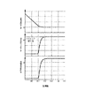
図12A〜図12Cは、一実施の形態における電動車両の制御装置による制御結果の一例を示す図である。 12A to 12C are diagrams illustrating an example of a control result by the control device for the electric vehicle in the embodiment.
図12A〜図12Cはそれぞれ、登坂路、平坦路、降坂路で停車する場合の制御結果であり、各図において、上から順にモータ回転速度、モータトルク指令値、車両前後加速度を表している。 12A to 12C show control results when the vehicle stops on an uphill road, a flat road, and a downhill road. In each figure, the motor rotation speed, the motor torque command value, and the vehicle longitudinal acceleration are shown in order from the top.
時刻t10では、図2のステップS202で算出される第1のトルク目標値Tm1*に基づいて、電動モータ4の減速が行われる。At time t10, the electric motor 4 is decelerated based on the first torque target value Tm1 * calculated in step S202 of FIG.
時刻t11において、停車間際判断トルクが第1のトルク目標値Tm1*より大きくなって停車間際と判断されることにより、モータトルク指令値Tm*が第1のトルク目標値Tm1*から第2のトルク目標値Tm2*に切り替わる。この後、モータ回転速度ωmの低下に応じて、モータトルク指令値Tm*は、外乱トルク推定値Tdに少しずつ近づいていく。At time t11, when the stop-stop determining torque is larger than the first torque target value Tm1 * and it is determined that the vehicle is about to stop, the motor torque command value Tm * is changed from the first torque target value Tm1 * to the second torque. The target value Tm2 * is switched to. Thereafter, as the motor rotation speed ωm decreases, the motor torque command value Tm * gradually approaches the estimated disturbance torque value Td.
時刻t13では、図12A〜図12Cに示すように、登坂路、平坦路、降坂路によらず、モータトルク指令値Tm*は外乱トルク推定値Tdに収束する。これにより、停車時に前後方向の加速度振動のない滑らかな停車を実現することができる。時刻t12以後は、登坂路、平坦路、降坂路によらず、モータ回転速度ωmは0であり、停車状態が維持されていることが分かる。At time t13, as shown in FIGS. 12A to 12C, the motor torque command value Tm * converges to the disturbance torque estimated value Td regardless of the uphill road, the flat road, and the downhill road. Thereby, the smooth stop without the acceleration vibration of the front-back direction at the time of a stop is realizable. After time t12, it can be seen that the motor rotation speed ωm is 0 regardless of the uphill road, the flat road, and the downhill road, and the stopped state is maintained.
続いて、図13〜15を参照して、アクセル操作量を加味した、より具体的な一実施の形態における電動車両の制御装置による制御結果について説明する。 Next, with reference to FIGS. 13 to 15, a description will be given of a control result by the control device for an electric vehicle in a more specific embodiment in consideration of the accelerator operation amount.
図13〜15は、図12と同様、一実施の形態における電動車両の制御装置による制御結果の一例を示す図である。図13は、アクセル操作量をゼロとした場合の制御結果、図14は、アクセル操作量を一定とした場合の制御結果、図15は、アクセル操作量を徐々に増加させた場合の制御結果を示している。図13(a)〜(c)、図14(a)〜(c)、図15(a)〜(c)はそれぞれ、登坂路、平坦路、降坂路で停車する場合の制御結果を表している。また、各図において、上から順にモータ回転速度、モータトルク指令値、車両前後加速度、および、アクセル開度を表している。 13-15 is a figure which shows an example of the control result by the control apparatus of the electric vehicle in one Embodiment similarly to FIG. FIG. 13 shows the control result when the accelerator operation amount is zero, FIG. 14 shows the control result when the accelerator operation amount is constant, and FIG. 15 shows the control result when the accelerator operation amount is gradually increased. Show. FIGS. 13 (a) to (c), FIGS. 14 (a) to (c), and FIGS. 15 (a) to (c) show control results when stopping on an uphill road, a flat road, and a downhill road, respectively. Yes. In each figure, the motor rotation speed, motor torque command value, vehicle longitudinal acceleration, and accelerator opening are shown in order from the top.
また、図13〜15においてモータトルク指令値を示す図には、モータトルク指令値(実線)および外乱トルク推定値(一点鎖線)に加えて、第1のトルク目標値(点線)、および、第2のトルク目標値(破線)を示している。 13 to 15 show the motor torque command value, in addition to the motor torque command value (solid line) and the disturbance torque estimated value (one-dot chain line), the first torque target value (dotted line), 2 shows a torque target value (broken line).
時刻t0では、図2のステップS202で算出される第1のトルク目標値Tm1*に基づいて、電動モータの減速が行われる。At time t0, the electric motor is decelerated based on the first torque target value Tm1 * calculated in step S202 of FIG.
時刻t1では、停車間際判断トルクが第1のトルク目標値Tm1*より大きくなって停車間際と判断されることにより、モータトルク指令値Tm*が第1のトルク目標値Tm1*から第2のトルク目標値Tm2*に切り替わる。この後、モータ回転速度ωmの低下に応じて、モータトルク指令値Tm*は、外乱トルク推定値Tdに少しずつ近づいていく。この間、図9〜11で示すとおり、モータトルク指令値Tm*は、アクセル操作量に依存せず、外乱トルク推定値Tdに収束していく。At the time t1, the stop torque immediately before the stop is greater than the first torque target value Tm1 * and it is determined that the vehicle is about to stop, so that the motor torque command value Tm * is changed from the first torque target value Tm1 * to the second torque. The target value Tm2 * is switched to. Thereafter, as the motor rotation speed ωm decreases, the motor torque command value Tm * gradually approaches the estimated disturbance torque value Td. During this time, as shown in FIGS. 9 to 11, the motor torque command value Tm * does not depend on the accelerator operation amount and converges to the disturbance torque estimated value Td.
時刻t3では、図13〜15の各図の(a)〜(c)に示すように、アクセル開度、および路面状況(登坂路、平坦路、降坂路)によらず、モータトルク指令値Tm*は、外乱トルク推定値Tdに収束する。これにより、停車時に前後方向の加速度振動のない滑らかな停車を実現することができる。時刻t3以後は、アクセル開度、路面状況によらず、モータ回転速度ωmは0であり、停車状態が維持されていることが分かる。At time t3, as shown in (a) to (c) of FIGS. 13 to 15, the motor torque command value Tm regardless of the accelerator opening and the road surface condition (uphill road, flat road, downhill road). * Converges to the estimated disturbance torque Td. Thereby, the smooth stop without the acceleration vibration of the front-back direction at the time of a stop is realizable. After the time t3, the motor rotation speed ωm is 0 regardless of the accelerator opening and the road surface condition, and it can be seen that the stopped state is maintained.
このように、停車間際判断トルクが第1のトルク目標値Tm1*より大きくなって停車間際と判断された場合は、アクセル操作量によらず、モータトルク指令値Tm*は、第1のトルク目標値Tm1*から第2のトルク目標値Tm2*に切り替わり、モータ回転速度の低下とともに外乱トルク推定値に収束する。なお、図13〜図15のモータトルク指令値および車両前後加速度の各図(a)のt2の直前に、図12には見られない滑らかでない部分があるが、作図の都合上現れたものであり、本願の作用効果に影響を及ぼすものではない。As described above, when it is determined that the vehicle stoppage determination torque is greater than the first torque target value Tm1 * and the vehicle is about to stop, the motor torque command value Tm * is the first torque target value regardless of the accelerator operation amount. The value Tm1 * is switched to the second torque target value Tm2 * , and converges to the disturbance torque estimated value as the motor rotation speed decreases. In addition, there is a non-smooth part that cannot be seen in FIG. 12 just before t2 in each of the figures (a) of the motor torque command values and vehicle longitudinal accelerations in FIGS. Yes, it does not affect the operational effects of the present application.
ここで、上述した説明では、モータ回転速度F/BトルクTωと外乱トルク推定値Tdとを加算することによって、第2のトルク目標値Tm2*を算出したが、モータ回転速度F/BトルクTωを第2のトルク目標値Tm2*として設定してもよい。図16は、モータ回転速度F/BトルクTωを第2のトルク目標値Tm2*として設定する場合において、停止制御処理を実現するためのブロック図である。図16において、図5に示す構成要素と同一の構成要素については、同一の符号を付している。Here, in the above description, the second torque target value Tm2 * is calculated by adding the motor rotation speed F / B torque Tω and the disturbance torque estimated value Td, but the motor rotation speed F / B torque Tω is calculated. May be set as the second torque target value Tm2 * . FIG. 16 is a block diagram for realizing the stop control process when the motor rotational speed F / B torque Tω is set as the second torque target value Tm2 * . In FIG. 16, the same components as those shown in FIG. 5 are denoted by the same reference numerals.
モータ回転速度F/BトルクTωを第2のトルク目標値Tm2*として設定した場合も、停車間際判断トルクが第1のトルク目標値Tm1*より大きくなって停車間際と判断されることにより、モータトルク指令値Tm*が第1のトルク目標値Tm1*から第2のトルク目標値Tm2*に切り替わる。このとき、第2のトルク目標値Tm2*は、モータ回転速度F/BトルクTωと略等しいため、モータ回転速度ωmの低下に応じて、モータトルク指令値Tm*はゼロに収束する。Even when the motor rotation speed F / B torque Tω is set as the second torque target value Tm2 * , it is determined that the vehicle stop-decision torque is greater than the first torque target value Tm1 * and the vehicle is about to stop. The torque command value Tm * is switched from the first torque target value Tm1 * to the second torque target value Tm2 * . At this time, since the second torque target value Tm2 * is substantially equal to the motor rotational speed F / B torque Tω, the motor torque command value Tm * converges to zero as the motor rotational speed ωm decreases.
以上、一実施の形態における電動車両の制御装置であるコントローラ4は、モータとしての電動モータ4を走行駆動源とし、電動モータ4の回生制動力により減速し、アクセル操作量を検出するとともに、モータトルク指令値を算出し、算出したモータトルク指令値に基づいて電動モータ4を制御する。 As described above, the controller 4, which is a control device for an electric vehicle in one embodiment, uses the electric motor 4 as a motor as a travel drive source, decelerates by the regenerative braking force of the electric motor 4, detects the accelerator operation amount, and the motor. A torque command value is calculated, and the electric motor 4 is controlled based on the calculated motor torque command value.
これと共に、電動車両の走行速度に比例する速度パラメータとしてモータ回転速度ωmを検出し、そのモータ回転速度ωmに基づいて電動車両を停止させるためのF/B(フィードバック)トルクを算出する。また電動車両の状態に応じて速度パラメータのモータ回転速度を推定し、その推定した値(モータ回転速度推定値)に基づいてF/Bトルクを補うためのF/F(フィードフォワード)トルクを算出する。 At the same time, the motor rotation speed ωm is detected as a speed parameter proportional to the traveling speed of the electric vehicle, and F / B (feedback) torque for stopping the electric vehicle is calculated based on the motor rotation speed ωm. Also, the motor rotational speed of the speed parameter is estimated according to the state of the electric vehicle, and F / F (feed forward) torque for compensating the F / B torque is calculated based on the estimated value (motor rotational speed estimated value). To do.
そして、アクセル操作量が所定値以下であり、かつ、電動車両が停車間際になると、走行速度に比例する速度パラメータの低下とともに、F/BトルクとF/Fトルクとに基づいてモータトルク指令値Tm*をゼロに収束させる。すなわち、コントローラ4は、アクセル操作量検出手段、車速検出手段、車速推定手段、フィードバックトルク算出手段、フィードフォワードトルク算出手段、モータトルク指令値算出手段、及びモータ制御手段として機能する。なお、アクセル操作量が所定値以下とは、回生制動とは別に、制動装置が介入することなく、十分に低速(例えば15km/h以下の速度)で走行しているときのアクセル操作量を意図している。なお、例に挙げた車速は一例であることは言うまでもない。When the accelerator operation amount is equal to or less than a predetermined value and the electric vehicle is about to stop, the motor torque command value is based on the F / B torque and the F / F torque along with a decrease in the speed parameter proportional to the traveling speed. Let Tm * converge to zero. That is, the controller 4 functions as accelerator operation amount detection means, vehicle speed detection means, vehicle speed estimation means, feedback torque calculation means, feed forward torque calculation means, motor torque command value calculation means, and motor control means. Note that the accelerator operation amount is equal to or less than the predetermined value is intended to be the accelerator operation amount when the vehicle is traveling at a sufficiently low speed (for example, a speed of 15 km / h or less) without intervention of a braking device, separately from regenerative braking. doing. Needless to say, the vehicle speeds mentioned in the examples are only examples.
これにより、アクセル操作量が所定値以下であり、かつ、電動車両が停車間際になると、電動車両の走行速度の低下とともにモータトルク指令値をゼロに収束させるので、前後方向における加速度振動のない滑らかな減速を停車間際で実現することができる。特に平坦路において、前後方向における加速度振動のない滑らかな減速を停車間際で実現することができ、かつ、停車状態を保持することができる。なお、走行速度の低下とは、車速がゼロに近づくことをいう。 As a result, when the accelerator operation amount is equal to or less than the predetermined value and the electric vehicle is about to stop, the motor torque command value converges to zero as the traveling speed of the electric vehicle decreases, so that there is no acceleration vibration in the front-rear direction. Slow deceleration can be realized just before stopping. Particularly on a flat road, smooth deceleration without acceleration vibration in the front-rear direction can be realized just before stopping, and the stopped state can be maintained. Note that the decrease in travel speed means that the vehicle speed approaches zero.
さらにF/FトルクをF/Bトルクと併用することにより、モータトルク指令値Tm*の振動を抑制するためにF/Bトルクを小さくし、その不足分をF/Fトルクにより補うことが可能となるので、制動距離を延ばすことなく制御系の安定性を確保できる。Furthermore, by using the F / F torque together with the F / B torque, the F / B torque can be reduced in order to suppress the vibration of the motor torque command value Tm * , and the shortage can be compensated by the F / F torque. Therefore, the stability of the control system can be ensured without increasing the braking distance.
また、フットブレーキなどの機械的制動手段によるブレーキ制動力を使わなくても車両を停車状態まで減速させることができるので、停車間際においても電動モータ4を回生運転させることができ、電費を向上させることができる。さらに、アクセル操作のみで車両の加減速および停車を実現することができるので、アクセルペダルとブレーキペダルの踏み替え操作が必要なく、ドライバの負担を軽減することができる。 In addition, since the vehicle can be decelerated to the stop state without using a brake braking force by a mechanical braking means such as a foot brake, the electric motor 4 can be regenerated even immediately before the stop, thereby improving the power consumption. be able to. Furthermore, since acceleration / deceleration and stopping of the vehicle can be realized only by the accelerator operation, it is not necessary to switch between the accelerator pedal and the brake pedal, and the burden on the driver can be reduced.
ドライバがブレーキペダルを用いて車両を停車させる場合、運転に慣れていないドライバはアクセルペダルを強く踏みすぎて、停車時に車両の前後方向に加速度振動が発生する。また、アクセル操作のみで車両の加減速および停車を実現する車両において、一定の減速度で減速および停車を実現しようとすると、減速時に十分な減速を実現するためには減速度を大きくする必要があるため、停車時に車両の前後方向に加速度振動が発生する。しかしながら、一実施の形態における電動車両の制御装置によれば、どのようなドライバであっても、上述したように、アクセル操作のみで滑らかな減速および停車を実現することができる。 When the driver uses the brake pedal to stop the vehicle, a driver who is not used to driving depresses the accelerator pedal too much, and acceleration vibration occurs in the front-rear direction of the vehicle when the vehicle stops. In addition, in a vehicle that realizes acceleration / deceleration and stopping of the vehicle only by the accelerator operation, if it is attempted to reduce and stop at a constant deceleration, it is necessary to increase the deceleration in order to achieve sufficient deceleration during deceleration. Therefore, acceleration vibration occurs in the front-rear direction of the vehicle when the vehicle is stopped. However, according to the control device for an electric vehicle in one embodiment, any driver can realize smooth deceleration and stop by only the accelerator operation as described above.
また、一実施の形態における電動車両の制御装置は、検出したモータ回転速度ωmに、モータの回生制動力を分配するための所定のゲインK1を乗算してF/Bトルクを算出し、所定のゲインK1に応じて設定される特定のゲインK2をモータ回転速度推定値に乗算してF/Fトルクを算出する。そして、アクセル操作量が所定値以下であり、かつ、電動車両が停車間際になると、F/BトルクにF/Fトルクを加算したモータ回転速度F/BトルクTωをモータトルク指令値Tm*として設定する。In addition, the control device for the electric vehicle in one embodiment calculates the F / B torque by multiplying the detected motor rotation speed ωm by a predetermined gain K1 for distributing the regenerative braking force of the motor, The F / F torque is calculated by multiplying the estimated motor rotation speed by a specific gain K2 set according to the gain K1. When the accelerator operation amount is equal to or less than a predetermined value and the electric vehicle is about to stop, the motor rotational speed F / B torque Tω obtained by adding the F / F torque to the F / B torque is set as the motor torque command value Tm *. Set.
モータ回転速度F/BトルクTωは、粘性(ダンパ)として働くため、停車間際においてモータ回転速度ωmは滑らか(漸近的に)にゼロに収束する。これにより、前後加速度にショックのない滑らかな停車を実現することができる。 Since the motor rotation speed F / B torque Tω acts as a viscosity (damper), the motor rotation speed ωm smoothly (asymptotically) converges to zero immediately before stopping. Thereby, the smooth stop without a shock in the longitudinal acceleration can be realized.
また、一実施の形態における電動車両の制御装置では、所定のゲインK1は、ゼロよりも小さく、車両を停止させるのに必要なトータルゲインKvrefよりも大きな値に設定される。そして特定のゲインK2は、トータルゲインKvrefから所定のゲインK1を減算した値に設定される。すなわち、ゲインK1とゲインK2とは、次式の関係を満たすように設定される。
式(11)の関係を満たすように、トータルゲインKvrefをゲインK1及びゲインK2に分配することにより、制動距離を延ばすことなく制御系の安定性を確保することができる。このため、システムに適した設定が可能となる。 By distributing the total gain Kvref to the gains K1 and K2 so as to satisfy the relationship of Expression (11), the stability of the control system can be ensured without increasing the braking distance. For this reason, a setting suitable for the system is possible.
さらに、一実施の形態における電動車両の制御装置では、車両モデルGp(s)に基づいてモータ回転速度推定値を算出し、モータ回転速度推定値の低下とともに車両モデルGp(s)へ入力されるモータトルク推定値がゼロに収束するF/F補償器501を備える。そしてF/F補償器501によりモータ回転速度推定値を取得する。なお、車両モデルGp(s)は、式(6)に示したように、電動車両へのトルク入力と電動モータ4の回転速度の伝達特性をモデル化したものである。
Furthermore, in the control apparatus for an electric vehicle in one embodiment, an estimated motor rotation speed is calculated based on the vehicle model Gp (s), and is input to the vehicle model Gp (s) along with a decrease in the estimated motor rotation speed. An F /
F/F補償器501を設けることにより、オープンループでモータ回転速度を推定することが可能になる。このため、モータ回転速度推定値によってモータトルク指令値Tm*を振動させないF/Fトルクを算出でき、このF/FトルクをF/Bトルクに加算することにより、制御系の安定性に影響を与えずにF/Bトルクの不足分を補うことができる。By providing the F /
また、一実施の形態における電動車両の制御装置では、F/F補償器501は、モータ回転速度推定値にトータルゲインKvrefを乗算してモータトルク推定値を算出し、そのモータトルク推定値を車両モデルGp(s)に入力してモータ回転速度推定値を算出する。
Further, in the control apparatus for an electric vehicle in one embodiment, F /
モータトルク推定値は、モータトルク推定値からモータ回転速度推定値までの動特性に対して粘性(ダンパ)要素として働くため、停車間際においてモータ回転速度推定値は滑らか(漸近的に)にゼロに収束する。これにより、前後加速度にショックのない滑らかな停車を実現することができる。 Since the estimated motor torque value acts as a viscous (damper) element for the dynamic characteristics from the estimated motor torque value to the estimated motor rotation speed value, the estimated motor rotation speed value becomes smooth (asymptotically) zero immediately before stopping. Converge. Thereby, the smooth stop without a shock in the longitudinal acceleration can be realized.
また、一実施の形態における電動車両の制御装置では、F/F補償器501には、車両モデルGp(s)として、式(10)の車両簡易モデルGp’(s)が用いられる。そしてF/F補償器501は、F/Fトルク設定器503に出力するモータ回転速度推定値に対しては、所定のローパスフィルタ処理Hc(s)を施す。また、F/F補償器501は、ローパスフィルタ処理Hc(s)を施していないモータ回転速度推定値に対しては、トータルゲインKvrefを乗算して得られるモータトルク推定値を車両簡易モデルGp’(s)に入力する。
In the control device for the electric vehicle according to the embodiment, the F /
このように、車両簡易モデルGp’(s)を使用し、F/Fトルクの算出に用いるモータ回転速度推定値についてのみ、ローパスフィルタ処理Hc(s)を行う。これにより、車両簡易モデルGp’(s)を使用に伴うF/Fトルクの応答特性のズレを調整することができる。 As described above, the low-pass filter process Hc (s) is performed only on the estimated motor rotation speed used for calculating the F / F torque using the vehicle simple model Gp ′ (s). Thereby, it is possible to adjust the deviation of the response characteristic of the F / F torque accompanying the use of the vehicle simple model Gp ′ (s).
したがって、F/F補償器501によるモータ回転速度の推定精度を確保しつつ、演算量を削減することができる。
Therefore, it is possible to reduce the amount of calculation while ensuring the estimation accuracy of the motor rotation speed by the F /
また、一実施の形態における電動車両の制御装置としてのコントローラ4は、車両情報に基づいて第1のトルク目標値Tm1*を算出する第1のトルク目標値算出手段、モータ回転速度フィードバックトルクTωを第2のトルク目標値Tm2*として算出する第2のトルク目標値算出手段、モータ回転速度ωmに所定のトータルゲインKvrefを乗算して得た値に外乱トルクを加算して停車間際判断トルクを算出する停車間際判断トルク算出手段、及び第1のトルク目標値Tm1*と停車間際判断トルクの大きさを比較するトルク比較手段として機能する。そして第1のトルク目標値Tm1*に対して前記停車間際判断トルクが大きいと判断した場合には、停車間際であると判断して、モータトルク指令値Tm*を第1のトルク目標値Tm1*から第2のトルク目標値Tm2*に切り替える。Further, the controller 4 as the control device for the electric vehicle according to the embodiment includes first torque target value calculation means for calculating the first torque target value Tm1 * based on the vehicle information, and motor rotation speed feedback torque Tω. Second torque target value calculation means for calculating the second torque target value Tm2 * , and calculating a stoppage stop judgment torque by adding a disturbance torque to a value obtained by multiplying the motor rotational speed ωm by a predetermined total gain Kvref. And a torque comparison means for comparing the first torque target value Tm1 * and the magnitude of the stop-stop determining torque. Then, when it is determined that the stop torque immediately before the stop is larger than the first torque target value Tm1 * , it is determined that the stop is just before stopping, and the motor torque command value Tm * is changed to the first torque target value Tm1 *. To the second torque target value Tm2 * .
これにより、車両情報に基づいた第1のトルク目標値Tm1*で減速した後に、停車間際において第2のトルク目標値Tm2*に切り替えて、減速からの滑らかな停車を実現することができる。また、第1のトルク目標値Tm1*と第2のトルク目標値Tm2*のうちの大きい方の値をモータトルク指令値Tm*に設定するので、いかなる勾配においても、トルク目標値の切り替えタイミングにおいてトルク段差が発生することがなく、滑らかな減速を実現することができる。Thereby, after decelerating at the first torque target value Tm1 * based on the vehicle information, it is possible to realize a smooth stop from deceleration by switching to the second torque target value Tm2 * immediately before stopping. In addition, since the larger one of the first torque target value Tm1 * and the second torque target value Tm2 * is set as the motor torque command value Tm * , the torque target value is switched at any timing. A torque step does not occur and smooth deceleration can be realized.
また、一実施の形態における電動車両の制御装置としてのコントローラ4は、外乱トルクを推定する外乱トルク推定手段として機能し、アクセル操作量が所定値以下であり、かつ、電動車両が停車間際になると、モータ回転速度の低下とともにモータトルク指令値Tm*を外乱トルクに収束させる。Further, the controller 4 as the control device for the electric vehicle in the embodiment functions as disturbance torque estimation means for estimating the disturbance torque, and when the accelerator operation amount is not more than a predetermined value and the electric vehicle is about to stop. As the motor rotation speed decreases, the motor torque command value Tm * is converged to disturbance torque.
これにより、登坂路、平坦路、降坂路によらず、前後方向における加速度振動のない滑らかな減速を停車間際で実現することができ、かつ、停車状態を保持することができる。 Accordingly, smooth deceleration without acceleration vibration in the front-rear direction can be realized just before the stop regardless of the uphill road, the flat road, and the downhill road, and the stop state can be maintained.
外乱トルクは、登坂路では正の値、降坂路では負の値になるので、坂路においても滑らかに停車し、フットブレーキを必要とせずに停車状態を保持することができる。また、平坦路では外乱トルク推定値Tdはゼロとなるので、平坦路において、滑らかに停車し、フットブレーキを必要とせずに停車状態を保持することができる。 The disturbance torque has a positive value on an uphill road and a negative value on a downhill road. Therefore, the disturbance torque can be smoothly stopped even on a slope, and the stopped state can be maintained without requiring a foot brake. Further, since the estimated disturbance torque value Td is zero on a flat road, the vehicle can be stopped smoothly on a flat road, and the stopped state can be maintained without requiring a foot brake.
一実施の形態における電動車両の制御装置では、モータ回転速度ωmを検出し、検出したモータ回転速度ωmに所定のゲインKvrefを乗算して、モータ回転速度フィードバックトルクTωを算出する。そして、アクセル操作量が所定値以下であり、かつ、電動車両が停車間際になると、モータ回転速度フィードバックトルクTωと外乱トルクTdとの和を、モータトルク指令値Tm*として算出する。In the control apparatus for an electric vehicle in one embodiment, the motor rotation speed ωm is detected, and the motor rotation speed feedback torque Tω is calculated by multiplying the detected motor rotation speed ωm by a predetermined gain Kvref. When the accelerator operation amount is equal to or less than a predetermined value and the electric vehicle is about to stop, the sum of the motor rotation speed feedback torque Tω and the disturbance torque Td is calculated as a motor torque command value Tm * .
モータ回転速度フィードバックトルクTωは、モータトルクからモータ回転速度までの動特性に対して粘性(ダンパ)として働くため、停車間際においてモータ回転速度ωmは滑らか(漸近的に)にゼロに収束する。これにより、前後加速度の振動を抑制した滑らかな停車を実現することができる。 Since the motor rotation speed feedback torque Tω acts as a viscosity (damper) on the dynamic characteristics from the motor torque to the motor rotation speed, the motor rotation speed ωm smoothly (asymptotically) converges to zero immediately before stopping. Thereby, the smooth stop which suppressed the vibration of the longitudinal acceleration is realizable.
また、車両へのトルク入力とモータの回転速度の伝達特性のモデルGp(s)に基づいて、外乱トルクを推定するので、精度良く外乱トルク推定値Tdを求めることができる。 Further, since the disturbance torque is estimated based on the model Gp (s) of the torque input to the vehicle and the transmission characteristic of the rotational speed of the motor, the disturbance torque estimated value Td can be obtained with high accuracy.
特に、モデルGp(s)と、分母次数と分子次数との差分が、モデルGp(s)の分母次数と分子次数との差分以上となる伝達特性H(s)とで構成されるH(s)/Gp(s)なる伝達特性を有するフィルタにモータ回転速度ωmを入力して第1のモータトルク推定値を算出するとともに、伝達特性H(s)を有するフィルタにモータトルク指令値Tm*を入力して第2のモータトルク推定値を算出し、第1のモータトルク推定値と第2のモータトルク推定値との偏差を演算することにより、外乱トルク推定値Tdを求める。これにより、精度良く外乱トルク推定値Tdを求めることができる。In particular, H (s) composed of the model Gp (s) and a transfer characteristic H (s) in which the difference between the denominator order and the numerator order is equal to or greater than the difference between the denominator order and the numerator order of the model Gp (s). ) / Gp (s) is input to the filter having the transfer characteristic to calculate the first motor torque estimated value, and the motor torque command value Tm * is applied to the filter having the transfer characteristic H (s). The input is used to calculate a second motor torque estimated value, and a disturbance torque estimated value Td is obtained by calculating a deviation between the first motor torque estimated value and the second motor torque estimated value. Thereby, the disturbance torque estimated value Td can be obtained with high accuracy.
一実施の形態における電動車両の制御装置としてのコントローラ4は、車両情報に基づいて第1のトルク目標値Tm1*を算出する第1のトルク目標値算出手段、モータ回転速度ωmの低下とともに外乱トルク推定値Tdに収束する第2のトルク目標値Tm2*を算出する第2のトルク目標値算出手段、モータ回転速度ωmに所定のトータルゲインKvrefを乗算して得た値に外乱トルクを加算して停車間際判断トルクを算出する停車間際判断トルク算出手段、及び第1のトルク目標値Tm1*と停車間際判断トルクの大きさを比較するトルク比較手段として機能する。そして第1のトルク目標値Tm1*に対して前記停車間際判断トルクが大きいと判断した場合には、停車間際であると判断して、モータトルク指令値Tm*を第1のトルク目標値Tm1*から第2のトルク目標値Tm2*に切り替える。The controller 4 as the control device for the electric vehicle according to the embodiment includes a first torque target value calculation unit that calculates a first torque target value Tm1 * based on vehicle information, and disturbance torque as the motor rotational speed ωm decreases. Second torque target value calculating means for calculating a second torque target value Tm2 * that converges to the estimated value Td, and adding disturbance torque to a value obtained by multiplying the motor rotational speed ωm by a predetermined total gain Kvref. It functions as a stop-time determination torque calculation means for calculating the stop-time determination torque, and a torque comparison means for comparing the first torque target value Tm1 * with the magnitude of the stop-time determination torque. Then, when it is determined that the stop torque immediately before the stop is larger than the first torque target value Tm1 * , it is determined that the stop is just before stopping, and the motor torque command value Tm * is changed to the first torque target value Tm1 *. To the second torque target value Tm2 * .
これにより、車両情報に基づいた第1のトルク目標値Tm1*で減速した後に、停車間際において第2のトルク目標値Tm2*に切り替えて、減速からの滑らかな停車を実現することができる。Thereby, after decelerating at the first torque target value Tm1 * based on the vehicle information, it is possible to realize a smooth stop from deceleration by switching to the second torque target value Tm2 * immediately before stopping.
本発明は、上述した一実施の形態に限定されることはない。例えば、上述した説明では、電動車両の走行速度に比例する速度パラメータとしてモータ回転速度を検出する例について説明した。しかし、車輪速や車体速度、ドライブシャフトの回転速度などについても、車両の走行速度と比例関係にあるため、速度パラメータとして用いることができる。 The present invention is not limited to the embodiment described above. For example, in the above description, the example in which the motor rotation speed is detected as a speed parameter proportional to the traveling speed of the electric vehicle has been described. However, the wheel speed, the vehicle body speed, the rotational speed of the drive shaft, and the like can also be used as speed parameters because they are proportional to the traveling speed of the vehicle.
例えば、電動車両の走行速度に比例する速度パラメータとして車輪速を検出し、その車輪速に基づいてF/Bトルクを算出するとともに、電動車両の状態に応じて車輪速を推定し、その推定値に基づいてF/Fトルクを算出するようにしてもよい。そして、アクセル操作量が所定値以下であり、かつ、電動車両が停車間際になると、車輪速によって定まる走行速度の低下とともにF/BトルクとF/Fトルクとに基づいてモータトルク指令値Tm*をゼロに収束させる。このようにモータ回転速度以外の速度パラメータを用いたとしても、本実施形態と同様の効果が得られる。For example, the wheel speed is detected as a speed parameter proportional to the traveling speed of the electric vehicle, the F / B torque is calculated based on the wheel speed, the wheel speed is estimated according to the state of the electric vehicle, and the estimated value The F / F torque may be calculated based on the above. When the accelerator operation amount is equal to or less than a predetermined value and the electric vehicle is about to stop, the motor torque command value Tm * is calculated based on the F / B torque and the F / F torque as the travel speed determined by the wheel speed decreases . To converge to zero. Thus, even if a speed parameter other than the motor rotation speed is used, the same effect as in the present embodiment can be obtained.
また、トルク比較器508は、第1のトルク目標値Tm1*に対して、停車間際判断トルクが大きいと判断した場合には、停車間際と判定してモータトルク指令値Tm*を第1のトルク目標値Tm1*から第2のトルク目標値Tm2*に切り替えるものとして説明した。しかし、トルク比較器508は、第1のトルク目標値Tm1*と第2のトルク目標値Tm2*の大きさを比較し、値が大きい方をモータトルク指令値Tm*に設定するようにしてもよい。Further, when the
以上、本発明の実施形態について説明したが、上記実施形態は本発明の適用例の一部を示したに過ぎず、本発明の技術的範囲を上記実施形態の具体的構成に限定する趣旨ではない。 As mentioned above, although embodiment of this invention was described, the said embodiment showed only a part of application example of this invention, and the meaning which limits the technical scope of this invention to the specific structure of the said embodiment. Absent.
本願は2013年12月2日に日本国特許庁に出願された特願2013−249098に基づく優先権を主張し、この出願の全ての内容は参照により本明細書に組み込まれる。 This application claims the priority based on Japanese Patent Application No. 2013-249098 for which it applied to the Japan Patent Office on December 2, 2013, and all the content of this application is integrated in this specification by reference.
Claims (9)
車両の加減速及び停止を指示するためのアクセルペダルと、
前記アクセルペダルの操作状態であるアクセル操作量を検出するアクセル操作量検出手段と、
前記電動車両の走行速度に比例する速度パラメータを検出する車速検出手段と、
前記電動車両の状態に応じて前記速度パラメータを推定する車速推定手段と、
前記車速検出手段により検出される速度パラメータに基づいて、前記電動車両を停止させるためのフィードバックトルクを算出するフィードバックトルク算出手段と、
前記車速推定手段により推定される速度パラメータに基づいて、前記フィードバックトルクの不足分を補うことで制動距離を短縮するためのフィードフォワードトルクを算出するフィードフォワードトルク算出手段と、
モータトルク指令値を算出するモータトルク指令値算出手段と、
外乱トルクを推定する外乱トルク推定手段と、
前記モータトルク指令値に基づいて、前記モータを制御するモータ制御手段と、
を備え、
前記フィードバックトルク算出手段は、前記車速検出手段により検出される前記速度パラメータに、前記モータの回生制動力を得られるトルクとしての前記フィードバックトルクと前記フィードフォワードトルクの割り当てを分配するための所定のゲインK1を乗算して、前記フィードバックトルクを算出し、
前記フィードフォワードトルク算出手段は、前記所定のゲインK1が大きくなるほど小さな値に設定される特定のゲインK2を、前記車速推定手段により推定される前記速度パラメータに乗算して、前記フィードフォワードトルクを算出し、
前記モータトルク指令値算出手段は、前記アクセルペダルが操作されることによって前記アクセル操作量が所定値以下となり、かつ、前記電動車両が停車間際になると、前記フィードバックトルクに前記フィードフォワードトルクを加算した速度フィードバックトルクと前記外乱トルクとの和を、前記モータトルク指令値として設定し、走行速度の低下とともに、当該モータトルク指令値を前記外乱トルクに収束させる、
電動車両の制御装置。 A control device for an electric vehicle using a motor as a travel drive source and capable of controlling from deceleration to stop of the vehicle by regenerative braking force of the motor,
An accelerator pedal for instructing acceleration / deceleration and stop of the vehicle;
An accelerator operation amount detection means for detecting an accelerator operation amount that is an operation state of the accelerator pedal;
Vehicle speed detecting means for detecting a speed parameter proportional to the traveling speed of the electric vehicle;
Vehicle speed estimation means for estimating the speed parameter according to the state of the electric vehicle;
Feedback torque calculating means for calculating feedback torque for stopping the electric vehicle based on a speed parameter detected by the vehicle speed detecting means;
Based on a speed parameter estimated by the vehicle speed estimating means, feedforward torque calculating means for calculating a feedforward torque for shortening a braking distance by compensating for a shortage of the feedback torque;
Motor torque command value calculating means for calculating a motor torque command value;
Disturbance torque estimating means for estimating the disturbance torque;
Motor control means for controlling the motor based on the motor torque command value;
With
The feedback torque calculating means is a predetermined gain for distributing the assignment of the feedback torque and the feedforward torque as torque that can obtain the regenerative braking force of the motor to the speed parameter detected by the vehicle speed detecting means. Multiply K1 to calculate the feedback torque,
The feedforward torque calculating means calculates the feedforward torque by multiplying the speed parameter estimated by the vehicle speed estimating means by a specific gain K2 set to a smaller value as the predetermined gain K1 increases. And
The motor torque command value calculating means adds the feed forward torque to the feedback torque when the accelerator operation amount becomes equal to or less than a predetermined value by operating the accelerator pedal and the electric vehicle is about to stop . the sum of the speed feedback torque and the disturbance torque, is set as the motor torque command value, with a decrease in travel speed, to converge the motor torque command value to the disturbance torque,
Control device for electric vehicle.
前記所定のゲインK1は、ゼロよりも小さく、前記モータトルク指令値をゼロに収束させるために定められたトータルゲインKvrefよりも大きな値に設定され、
前記特定のゲインK2は、前記トータルゲインKvrefから前記所定のゲインK1を減算した値に設定される、
電動車両の制御装置。 In the control apparatus of the electric vehicle according to claim 1 ,
The predetermined gain K1 is set to a value smaller than zero and larger than a total gain Kvref determined in order to converge the motor torque command value to zero,
The specific gain K2 is set to a value obtained by subtracting the predetermined gain K1 from the total gain Kvref.
Control device for electric vehicle.
前記車速推定手段は、前記電動車両へのトルク入力と前記モータの回転速度の伝達特性のモデルGp(s)に基づいて前記モータの回転速度を推定し、当該モータの回転速度の低下とともに前記モデルGp(s)へ入力されるモータトルク推定値がゼロに収束するフィードフォワード補償器を備え、
前記車速推定手段は、前記フィードフォワード補償器で推定される前記モータの回転速度を前記速度パラメータとして取得する、
電動車両の制御装置。 In the control apparatus of the electric vehicle according to claim 1 or 2 ,
The vehicle speed estimation means estimates the rotation speed of the motor based on a model Gp (s) of transmission characteristics of torque input to the electric vehicle and the rotation speed of the motor, and reduces the rotation speed of the motor along with the model. A feedforward compensator in which the estimated motor torque input to Gp (s) converges to zero;
The vehicle speed estimation means acquires the rotation speed of the motor estimated by the feedforward compensator as the speed parameter.
Control device for electric vehicle.
前記フィードフォワード補償器は、前記モータの回転速度を推定した値に予め定められた負の値であるトータルゲインKvrefを乗算して前記モータトルク推定値を算出し、当該モータトルク推定値を前記モデルGp(s)に入力して前記モータの回転速度を推定した値を出力する、
電動車両の制御装置。 In the control apparatus of the electric vehicle according to claim 3 ,
The feedforward compensator calculates the motor torque estimated value by multiplying a value obtained by estimating the rotation speed of the motor by a predetermined negative total gain Kvref, and calculates the motor torque estimated value to the model. Input to Gp (s) and output a value that estimates the rotational speed of the motor.
Control device for electric vehicle.
前記フィードフォワード補償器は、前記モデルGp(s)として、前記モデルGp(s)を簡易化した一次関数で表される簡易モデルGp’(s)を使用し、前記フィードフォワードトルク算出手段に出力する前記モータの回転速度を推定した値に対しては、所定のローパスフィルタ処理Hc(s)を施し、
前記フィードフォワード補償器は、前記ローパスフィルタ処理Hc(s)を施していない前記モータの回転速度を推定した値に対しては、前記トータルゲインKvrefを乗算して前記モータトルク推定値を前記簡易モデルGp’(s)に入力する、
電動車両の制御装置。 In the control apparatus of the electric vehicle according to claim 4 ,
The feedforward compensator uses, as the model Gp (s), a simplified model Gp ′ (s) represented by a linear function obtained by simplifying the model Gp (s), and outputs it to the feedforward torque calculation unit. A predetermined low-pass filter process Hc (s) is applied to the estimated value of the rotational speed of the motor,
The feedforward compensator multiplies the total gain Kvref by multiplying the estimated value of the motor torque that has not been subjected to the low-pass filter processing Hc (s) by the total gain Kvref to obtain the motor torque estimated value. Enter in Gp ′ (s),
Control device for electric vehicle.
前記外乱トルク推定手段は、前記外乱トルクを、登坂路では正の値、降坂路では負の値として推定する、
電動車両の制御装置。 In the control apparatus of the electric vehicle as described in any one of Claims 1-5 ,
The disturbance torque estimating means estimates the disturbance torque as a positive value on an uphill road and a negative value on a downhill road,
Control device for electric vehicle.
前記外乱トルク推定手段は、平坦路では前記外乱トルクをゼロとする、
電動車両の制御装置。 In the control apparatus of the electric vehicle as described in any one of Claims 1-6 ,
The disturbance torque estimating means sets the disturbance torque to zero on a flat road,
Control device for electric vehicle.
車両情報に基づいて第1のトルク目標値を算出する第1のトルク目標値算出手段と、
前記車速検出手段により検出される前記速度パラメータの低下とともに前記外乱トルクに収束する第2のトルク目標値を算出する第2のトルク目標値算出手段と、
前記車速検出手段により検出される前記速度パラメータに予め定められた負の値であるトータルゲインKvrefを乗算して得た値に外乱トルクを加算して停車間際判断トルクを算出する停車間際判断トルク算出手段と、
前記第1のトルク目標値と前記停車間際判断トルクの大きさを比較するトルク比較手段と、
をさらに備え、
前記モータトルク指令値算出手段は、前記第1のトルク目標値に対して前記停車間際判断トルクが大きいと判断した場合には、停車間際であると判断して、前記モータトルク指令値を前記第1のトルク目標値から前記第2のトルク目標値に切り替える、
電動車両の制御装置。 The control apparatus for an electric vehicle according to any one of claims 1 to 7,
First torque target value calculating means for calculating a first torque target value based on vehicle information;
Second torque target value calculating means for calculating a second torque target value that converges to the disturbance torque with a decrease in the speed parameter detected by the vehicle speed detecting means;
A stop-time determination torque calculation that adds a disturbance torque to a value obtained by multiplying the speed parameter detected by the vehicle speed detection means by a predetermined negative total gain Kvref to calculate a stop-time determination torque. Means,
Torque comparing means for comparing the first torque target value with the magnitude of the stop-stop determining torque;
Further comprising
The motor torque command value calculating means determines that the vehicle torque command value is about to stop when the motor torque command value calculating unit determines that the stop torque immediately before stopping is larger than the first torque target value. Switching from a torque target value of 1 to the second torque target value;
Control device for electric vehicle.
前記アクセルペダルの操作状態である前記アクセル操作量を検出するアクセル操作量検出ステップと、
前記電動車両の走行速度に比例する速度パラメータを検出する車速検出ステップと、
前記電動車両の状態に応じて前記速度パラメータを推定する車速推定ステップと、
前記車速検出ステップで検出される速度パラメータに基づいて、前記電動車両を停止させるためのフィードバックトルクを算出するフィードバックトルク算出ステップと、
車速推定ステップで推定される速度パラメータに基づいて、前記フィードバックトルクの不足分を補うことで制動距離を短縮するためのフィードフォワードトルクを算出するフィードフォワードトルク算出ステップと、
モータトルク指令値を算出するモータトルク指令値算出ステップと、
外乱トルクを推定する外乱トルク推定ステップと、
前記モータトルク指令値に基づいて、前記モータを制御するモータ制御ステップと、
を備え、
前記フィードバックトルク算出ステップでは、前記車速検出手段により検出される前記速度パラメータに、前記モータの回生制動力を得られるトルクとしての前記フィードバックトルクと前記フィードフォワードトルクの割り当てを分配するための所定のゲインK1を乗算して、前記フィードバックトルクを算出し、
前記フィードフォワードトルク算出ステップでは、前記所定のゲインK1が大きくなるほど小さな値に設定される特定のゲインK2を、前記車速推定手段により推定される前記速度パラメータに乗算して、前記フィードフォワードトルクを算出し、
前記モータトルク指令値算出ステップでは、前記アクセルペダルが操作されることによって前記アクセル操作量が所定値以下となり、かつ、前記電動車両が停車間際になると、前記フィードバックトルクに前記フィードフォワードトルクを加算した速度フィードバックトルクと前記外乱トルクとの和を、前記モータトルク指令値として設定し、走行速度の低下とともに、当該モータトルク指令値を前記外乱トルクに収束させる、
電動車両の制御方法。 This is a method for controlling an electric vehicle that uses a motor as a travel drive source, has an accelerator pedal for instructing acceleration / deceleration and stop of the electric vehicle, and can control from deceleration to stop of the vehicle by the regenerative braking force of the motor. And
An accelerator operation amount detection step of detecting the accelerator operation amount which is an operation state of the accelerator pedal;
A vehicle speed detecting step for detecting a speed parameter proportional to the traveling speed of the electric vehicle;
A vehicle speed estimating step for estimating the speed parameter according to a state of the electric vehicle;
A feedback torque calculating step for calculating a feedback torque for stopping the electric vehicle based on the speed parameter detected in the vehicle speed detecting step;
Based on the speed parameter estimated in the vehicle speed estimation step, a feed forward torque calculation step for calculating a feed forward torque for shortening the braking distance by compensating for the shortage of the feedback torque;
A motor torque command value calculating step for calculating a motor torque command value;
A disturbance torque estimating step for estimating a disturbance torque;
A motor control step for controlling the motor based on the motor torque command value;
With
In the feedback torque calculating step, a predetermined gain for distributing the allocation of the feedback torque and the feedforward torque as torque that can obtain the regenerative braking force of the motor to the speed parameter detected by the vehicle speed detecting means Multiply K1 to calculate the feedback torque,
In the feedforward torque calculating step, the feedforward torque is calculated by multiplying the speed parameter estimated by the vehicle speed estimating means by a specific gain K2 set to a smaller value as the predetermined gain K1 increases. And
In the motor torque command value calculating step, when the accelerator pedal is operated, the accelerator operation amount becomes a predetermined value or less, and when the electric vehicle is about to stop, the feedforward torque is added to the feedback torque. the sum of the speed feedback torque and the disturbance torque, is set as the motor torque command value, with a decrease in travel speed, to converge the motor torque command value to the disturbance torque,
Control method of electric vehicle.
Applications Claiming Priority (3)
| Application Number | Priority Date | Filing Date | Title |
|---|---|---|---|
| JP2013249098 | 2013-12-02 | ||
| JP2013249098 | 2013-12-02 | ||
| PCT/JP2014/080819 WO2015083557A1 (en) | 2013-12-02 | 2014-11-20 | Control device for electric vehicle and control method for electric vehicle |
Publications (2)
| Publication Number | Publication Date |
|---|---|
| JPWO2015083557A1 JPWO2015083557A1 (en) | 2017-03-16 |
| JP6330820B2 true JP6330820B2 (en) | 2018-05-30 |
Family
ID=53273324
Family Applications (1)
| Application Number | Title | Priority Date | Filing Date |
|---|---|---|---|
| JP2015551461A Active JP6330820B2 (en) | 2013-12-02 | 2014-11-20 | Electric vehicle control device and electric vehicle control method |
Country Status (5)
| Country | Link |
|---|---|
| US (1) | US9845022B2 (en) |
| EP (1) | EP3078539B1 (en) |
| JP (1) | JP6330820B2 (en) |
| CN (1) | CN105764742B (en) |
| WO (1) | WO2015083557A1 (en) |
Families Citing this family (19)
| Publication number | Priority date | Publication date | Assignee | Title |
|---|---|---|---|---|
| KR101921851B1 (en) | 2015-01-26 | 2018-11-23 | 닛산 지도우샤 가부시키가이샤 | Control device of electric vehicle and control method of electric vehicle |
| BR112018009419B1 (en) * | 2015-11-09 | 2022-09-06 | Nissan Motor Co., Ltd. | BRAKE/DRIVE FORCE CONTROL METHOD AND BRAKE/DRIVE FORCE CONTROL DEVICE |
| JP6729002B2 (en) * | 2016-06-03 | 2020-07-22 | 日産自動車株式会社 | Electric vehicle control method and control device |
| US10158303B2 (en) * | 2016-09-15 | 2018-12-18 | The Boeing Company | Methods and apparatus to perform torque balance control of co-shafted motors |
| CN108263246B (en) * | 2016-12-30 | 2020-01-03 | 长城汽车股份有限公司 | Torque filtering control method and system of vehicle and vehicle |
| CN110691710B (en) * | 2017-06-01 | 2020-10-16 | 日产自动车株式会社 | Control method and control device for electric vehicle |
| JP6992298B2 (en) * | 2017-07-18 | 2022-01-13 | 日産自動車株式会社 | Electric vehicle control device and electric vehicle control method |
| CN108790937B (en) * | 2018-03-12 | 2021-10-29 | 上海伊控动力系统有限公司 | Steep slope slow descending method and system for electric automobile |
| JP6814192B2 (en) * | 2018-11-26 | 2021-01-13 | 本田技研工業株式会社 | Vehicle control devices, vehicle control methods, and programs |
| CN109591608B (en) * | 2018-12-03 | 2020-12-22 | 潍柴动力股份有限公司 | Electric automobile brake control method, whole automobile control device and system |
| JP7132862B2 (en) * | 2019-01-29 | 2022-09-07 | 日立Astemo株式会社 | CONTROL DEVICE, CONTROL METHOD, AND CONTROL SYSTEM FOR ELECTRIC VEHICLE |
| EP3950402B1 (en) * | 2019-03-27 | 2023-06-07 | NISSAN MOTOR Co., Ltd. | Control apparatus for electric vehicle and control method for electric vehicle |
| AT522508B1 (en) * | 2019-05-13 | 2022-02-15 | Avl List Gmbh | Process for controlling the drive of an electric vehicle |
| CN114222680A (en) * | 2019-08-15 | 2022-03-22 | 日本电产株式会社 | Vibration damping control device and vibration damping control method |
| JP7190665B2 (en) * | 2019-12-24 | 2022-12-16 | パナソニックIpマネジメント株式会社 | Vehicle control device and vehicle |
| CN112660129B (en) * | 2020-12-21 | 2022-05-17 | 浙江天尚元科技有限公司 | Intelligent line control chassis acceleration control system and control method |
| CN112606708B (en) * | 2020-12-29 | 2023-01-10 | 联合汽车电子有限公司 | New energy automobile power control method, system, equipment and storage medium |
| US11752881B2 (en) * | 2021-01-20 | 2023-09-12 | GM Global Technology Operations LLC | Intelligent vehicles and control logic for brake torque request estimation for cooperative brake system control |
| CN115556726B (en) * | 2022-12-01 | 2023-03-03 | 小米汽车科技有限公司 | Braking efficiency degradation compensation method, device, vehicle and storage medium |
Family Cites Families (16)
| Publication number | Priority date | Publication date | Assignee | Title |
|---|---|---|---|---|
| JP3287877B2 (en) * | 1992-07-30 | 2002-06-04 | トヨタ自動車株式会社 | Electric vehicle torque control device |
| JPH0879907A (en) | 1994-09-01 | 1996-03-22 | Mitsubishi Motors Corp | Regenerative brake controller for electric automobile |
| JPH09130911A (en) * | 1995-10-31 | 1997-05-16 | Sanyo Electric Co Ltd | Drive controller for electric automobile |
| US6554088B2 (en) * | 1998-09-14 | 2003-04-29 | Paice Corporation | Hybrid vehicles |
| JP2001145204A (en) * | 1999-11-17 | 2001-05-25 | Akebono Brake Res & Dev Center Ltd | Brake controller of motor-driven vehicle |
| JP2002186108A (en) | 2000-12-15 | 2002-06-28 | Nissan Motor Co Ltd | Device for adjusting revolution of engine and device for controlling hybrid power unit |
| JP3508742B2 (en) * | 2001-06-18 | 2004-03-22 | 日産自動車株式会社 | Vehicle vibration suppression control device using electric motor |
| JP3404388B2 (en) * | 2001-10-26 | 2003-05-06 | 三菱電機株式会社 | Motor control method |
| JP2006022403A (en) * | 2004-06-08 | 2006-01-26 | Kanazawa Inst Of Technology | Method for inhibiting organic compound from adsorbing onto surface of article molded from synthetic resin |
| JP2006224703A (en) | 2005-02-15 | 2006-08-31 | Toyota Motor Corp | Driving device, vehicle with the device mounted thereon, and method for controlling the device |
| JP4396717B2 (en) * | 2007-03-07 | 2010-01-13 | トヨタ自動車株式会社 | Vehicle control apparatus, control method, program for realizing the method, and recording medium recording the program |
| US8847522B2 (en) * | 2008-11-14 | 2014-09-30 | Denso Corporation | Reluctance motor with improved stator structure |
| JP5455802B2 (en) * | 2010-06-11 | 2014-03-26 | 日立建機株式会社 | Pitching control device for electric vehicle |
| JP5915208B2 (en) * | 2012-01-31 | 2016-05-11 | 日産自動車株式会社 | Regenerative brake control device for electric vehicle |
| EP2839983B1 (en) * | 2012-04-18 | 2020-11-25 | Nissan Motor Co., Ltd. | Electric-vehicle control device, and method for controlling electric vehicle |
| JP5861554B2 (en) | 2012-04-18 | 2016-02-16 | 日産自動車株式会社 | Vibration suppression control device for vehicle |
-
2014
- 2014-11-20 JP JP2015551461A patent/JP6330820B2/en active Active
- 2014-11-20 CN CN201480064432.7A patent/CN105764742B/en active Active
- 2014-11-20 WO PCT/JP2014/080819 patent/WO2015083557A1/en active Application Filing
- 2014-11-20 EP EP14867010.2A patent/EP3078539B1/en active Active
- 2014-11-20 US US15/100,928 patent/US9845022B2/en active Active
Also Published As
| Publication number | Publication date |
|---|---|
| CN105764742B (en) | 2018-04-27 |
| JPWO2015083557A1 (en) | 2017-03-16 |
| CN105764742A (en) | 2016-07-13 |
| EP3078539A1 (en) | 2016-10-12 |
| US9845022B2 (en) | 2017-12-19 |
| WO2015083557A1 (en) | 2015-06-11 |
| EP3078539A4 (en) | 2016-11-23 |
| EP3078539B1 (en) | 2019-07-24 |
| US20160297321A1 (en) | 2016-10-13 |
Similar Documents
| Publication | Publication Date | Title |
|---|---|---|
| JP6330820B2 (en) | Electric vehicle control device and electric vehicle control method | |
| JP6233420B2 (en) | Electric vehicle control device and electric vehicle control method | |
| JP6135775B2 (en) | Electric vehicle control device and electric vehicle control method | |
| JP6402782B2 (en) | Electric vehicle control device and electric vehicle control method | |
| JP6402783B2 (en) | Electric vehicle control device and electric vehicle control method | |
| CN110234533B (en) | Control method and control device for electric vehicle | |
| JP6492399B2 (en) | Electric vehicle control device and electric vehicle control method | |
| CN110191818B (en) | Method for controlling electric vehicle and device for controlling electric vehicle | |
| JP6760401B2 (en) | Electric vehicle control method and control device | |
| WO2017017816A1 (en) | Electric vehicle control device and electric vehicle control method | |
| JP6540716B2 (en) | Vehicle control apparatus and vehicle control method | |
| CN114599544B (en) | Control method for electric vehicle and control device for electric vehicle | |
| JP6237789B2 (en) | Electric vehicle control device and electric vehicle control method | |
| JP2017220971A (en) | Control method for electric vehicle, and control apparatus | |
| JP7056219B2 (en) | Motor vehicle control method and motor vehicle control device | |
| JP6880674B2 (en) | Electric vehicle control method and electric vehicle control device | |
| JP2019022339A (en) | Control device of electric vehicle and control method of electric vehicle | |
| WO2015079574A1 (en) | Control device for electric vehicle and control method for electric vehicle |
Legal Events
| Date | Code | Title | Description |
|---|---|---|---|
| RD02 | Notification of acceptance of power of attorney |
Free format text: JAPANESE INTERMEDIATE CODE: A7422 Effective date: 20161205 |
|
| A131 | Notification of reasons for refusal |
Free format text: JAPANESE INTERMEDIATE CODE: A131 Effective date: 20170328 |
|
| A521 | Written amendment |
Free format text: JAPANESE INTERMEDIATE CODE: A523 Effective date: 20170511 |
|
| A02 | Decision of refusal |
Free format text: JAPANESE INTERMEDIATE CODE: A02 Effective date: 20171031 |
|
| A521 | Written amendment |
Free format text: JAPANESE INTERMEDIATE CODE: A523 Effective date: 20180124 |
|
| A911 | Transfer of reconsideration by examiner before appeal (zenchi) |
Free format text: JAPANESE INTERMEDIATE CODE: A911 Effective date: 20180131 |
|
| TRDD | Decision of grant or rejection written | ||
| A01 | Written decision to grant a patent or to grant a registration (utility model) |
Free format text: JAPANESE INTERMEDIATE CODE: A01 Effective date: 20180327 |
|
| A61 | First payment of annual fees (during grant procedure) |
Free format text: JAPANESE INTERMEDIATE CODE: A61 Effective date: 20180409 |
|
| R151 | Written notification of patent or utility model registration |
Ref document number: 6330820 Country of ref document: JP Free format text: JAPANESE INTERMEDIATE CODE: R151 |