JP6329068B2 - Panel support device - Google Patents
Panel support device Download PDFInfo
- Publication number
- JP6329068B2 JP6329068B2 JP2014504276A JP2014504276A JP6329068B2 JP 6329068 B2 JP6329068 B2 JP 6329068B2 JP 2014504276 A JP2014504276 A JP 2014504276A JP 2014504276 A JP2014504276 A JP 2014504276A JP 6329068 B2 JP6329068 B2 JP 6329068B2
- Authority
- JP
- Japan
- Prior art keywords
- plastic casing
- photovoltaic panel
- fixing
- photovoltaic
- upper wall
- Prior art date
- Legal status (The legal status is an assumption and is not a legal conclusion. Google has not performed a legal analysis and makes no representation as to the accuracy of the status listed.)
- Expired - Fee Related
Links
- 238000007667 floating Methods 0.000 claims description 16
- 238000012423 maintenance Methods 0.000 claims description 13
- 210000005069 ears Anatomy 0.000 claims description 12
- 230000000295 complement effect Effects 0.000 claims description 10
- 238000000034 method Methods 0.000 claims description 7
- 238000010101 extrusion blow moulding Methods 0.000 claims description 6
- 238000013022 venting Methods 0.000 claims description 6
- 229920001971 elastomer Polymers 0.000 claims description 5
- 239000000806 elastomer Substances 0.000 claims description 5
- 238000010248 power generation Methods 0.000 claims description 4
- 238000004519 manufacturing process Methods 0.000 claims description 3
- 238000009423 ventilation Methods 0.000 claims 3
- 238000004891 communication Methods 0.000 claims 1
- 238000009434 installation Methods 0.000 description 6
- 238000001175 rotational moulding Methods 0.000 description 6
- XLYOFNOQVPJJNP-UHFFFAOYSA-N water Substances O XLYOFNOQVPJJNP-UHFFFAOYSA-N 0.000 description 6
- 238000010586 diagram Methods 0.000 description 5
- 238000001816 cooling Methods 0.000 description 3
- 239000013536 elastomeric material Substances 0.000 description 3
- 239000000463 material Substances 0.000 description 3
- 238000000465 moulding Methods 0.000 description 3
- 125000006850 spacer group Chemical group 0.000 description 3
- 238000004873 anchoring Methods 0.000 description 2
- 238000005516 engineering process Methods 0.000 description 2
- 238000001125 extrusion Methods 0.000 description 2
- 230000002265 prevention Effects 0.000 description 2
- 238000000926 separation method Methods 0.000 description 2
- 239000000243 solution Substances 0.000 description 2
- 238000005273 aeration Methods 0.000 description 1
- 238000004140 cleaning Methods 0.000 description 1
- 239000002131 composite material Substances 0.000 description 1
- 230000008878 coupling Effects 0.000 description 1
- 238000010168 coupling process Methods 0.000 description 1
- 238000005859 coupling reaction Methods 0.000 description 1
- 230000000694 effects Effects 0.000 description 1
- 230000005484 gravity Effects 0.000 description 1
- 238000001746 injection moulding Methods 0.000 description 1
- 230000010354 integration Effects 0.000 description 1
- 239000007788 liquid Substances 0.000 description 1
- 239000002184 metal Substances 0.000 description 1
- 238000006213 oxygenation reaction Methods 0.000 description 1
- 230000005855 radiation Effects 0.000 description 1
- 239000004576 sand Substances 0.000 description 1
- 230000035945 sensitivity Effects 0.000 description 1
- 230000035939 shock Effects 0.000 description 1
- 238000003856 thermoforming Methods 0.000 description 1
Images


Classifications
-
- F—MECHANICAL ENGINEERING; LIGHTING; HEATING; WEAPONS; BLASTING
- F24—HEATING; RANGES; VENTILATING
- F24S—SOLAR HEAT COLLECTORS; SOLAR HEAT SYSTEMS
- F24S30/00—Arrangements for moving or orienting solar heat collector modules
- F24S30/20—Arrangements for moving or orienting solar heat collector modules for linear movement
-
- H—ELECTRICITY
- H02—GENERATION; CONVERSION OR DISTRIBUTION OF ELECTRIC POWER
- H02S—GENERATION OF ELECTRIC POWER BY CONVERSION OF INFRARED RADIATION, VISIBLE LIGHT OR ULTRAVIOLET LIGHT, e.g. USING PHOTOVOLTAIC [PV] MODULES
- H02S20/00—Supporting structures for PV modules
-
- F—MECHANICAL ENGINEERING; LIGHTING; HEATING; WEAPONS; BLASTING
- F24—HEATING; RANGES; VENTILATING
- F24S—SOLAR HEAT COLLECTORS; SOLAR HEAT SYSTEMS
- F24S20/00—Solar heat collectors specially adapted for particular uses or environments
- F24S20/70—Waterborne solar heat collector modules
-
- F—MECHANICAL ENGINEERING; LIGHTING; HEATING; WEAPONS; BLASTING
- F24—HEATING; RANGES; VENTILATING
- F24S—SOLAR HEAT COLLECTORS; SOLAR HEAT SYSTEMS
- F24S25/00—Arrangement of stationary mountings or supports for solar heat collector modules
- F24S25/10—Arrangement of stationary mountings or supports for solar heat collector modules extending in directions away from a supporting surface
- F24S25/11—Arrangement of stationary mountings or supports for solar heat collector modules extending in directions away from a supporting surface using shaped bodies, e.g. concrete elements, foamed elements or moulded box-like elements
-
- F—MECHANICAL ENGINEERING; LIGHTING; HEATING; WEAPONS; BLASTING
- F24—HEATING; RANGES; VENTILATING
- F24S—SOLAR HEAT COLLECTORS; SOLAR HEAT SYSTEMS
- F24S25/00—Arrangement of stationary mountings or supports for solar heat collector modules
- F24S25/60—Fixation means, e.g. fasteners, specially adapted for supporting solar heat collector modules
- F24S25/65—Fixation means, e.g. fasteners, specially adapted for supporting solar heat collector modules for coupling adjacent supporting elements, e.g. for connecting profiles together
-
- H—ELECTRICITY
- H02—GENERATION; CONVERSION OR DISTRIBUTION OF ELECTRIC POWER
- H02S—GENERATION OF ELECTRIC POWER BY CONVERSION OF INFRARED RADIATION, VISIBLE LIGHT OR ULTRAVIOLET LIGHT, e.g. USING PHOTOVOLTAIC [PV] MODULES
- H02S20/00—Supporting structures for PV modules
- H02S20/10—Supporting structures directly fixed to the ground
-
- H—ELECTRICITY
- H02—GENERATION; CONVERSION OR DISTRIBUTION OF ELECTRIC POWER
- H02S—GENERATION OF ELECTRIC POWER BY CONVERSION OF INFRARED RADIATION, VISIBLE LIGHT OR ULTRAVIOLET LIGHT, e.g. USING PHOTOVOLTAIC [PV] MODULES
- H02S20/00—Supporting structures for PV modules
- H02S20/20—Supporting structures directly fixed to an immovable object
- H02S20/22—Supporting structures directly fixed to an immovable object specially adapted for buildings
- H02S20/23—Supporting structures directly fixed to an immovable object specially adapted for buildings specially adapted for roof structures
- H02S20/24—Supporting structures directly fixed to an immovable object specially adapted for buildings specially adapted for roof structures specially adapted for flat roofs
-
- H—ELECTRICITY
- H02—GENERATION; CONVERSION OR DISTRIBUTION OF ELECTRIC POWER
- H02S—GENERATION OF ELECTRIC POWER BY CONVERSION OF INFRARED RADIATION, VISIBLE LIGHT OR ULTRAVIOLET LIGHT, e.g. USING PHOTOVOLTAIC [PV] MODULES
- H02S30/00—Structural details of PV modules other than those related to light conversion
- H02S30/10—Frame structures
-
- H—ELECTRICITY
- H02—GENERATION; CONVERSION OR DISTRIBUTION OF ELECTRIC POWER
- H02S—GENERATION OF ELECTRIC POWER BY CONVERSION OF INFRARED RADIATION, VISIBLE LIGHT OR ULTRAVIOLET LIGHT, e.g. USING PHOTOVOLTAIC [PV] MODULES
- H02S40/00—Components or accessories in combination with PV modules, not provided for in groups H02S10/00 - H02S30/00
- H02S40/40—Thermal components
- H02S40/42—Cooling means
- H02S40/425—Cooling means using a gaseous or a liquid coolant, e.g. air flow ventilation, water circulation
-
- B—PERFORMING OPERATIONS; TRANSPORTING
- B63—SHIPS OR OTHER WATERBORNE VESSELS; RELATED EQUIPMENT
- B63B—SHIPS OR OTHER WATERBORNE VESSELS; EQUIPMENT FOR SHIPPING
- B63B35/00—Vessels or similar floating structures specially adapted for specific purposes and not otherwise provided for
- B63B35/44—Floating buildings, stores, drilling platforms, or workshops, e.g. carrying water-oil separating devices
- B63B2035/4433—Floating structures carrying electric power plants
- B63B2035/4453—Floating structures carrying electric power plants for converting solar energy into electric energy
-
- B—PERFORMING OPERATIONS; TRANSPORTING
- B63—SHIPS OR OTHER WATERBORNE VESSELS; RELATED EQUIPMENT
- B63B—SHIPS OR OTHER WATERBORNE VESSELS; EQUIPMENT FOR SHIPPING
- B63B2209/00—Energy supply or activating means
- B63B2209/18—Energy supply or activating means solar energy
-
- F—MECHANICAL ENGINEERING; LIGHTING; HEATING; WEAPONS; BLASTING
- F24—HEATING; RANGES; VENTILATING
- F24S—SOLAR HEAT COLLECTORS; SOLAR HEAT SYSTEMS
- F24S25/00—Arrangement of stationary mountings or supports for solar heat collector modules
- F24S25/60—Fixation means, e.g. fasteners, specially adapted for supporting solar heat collector modules
- F24S2025/6003—Fixation means, e.g. fasteners, specially adapted for supporting solar heat collector modules by clamping
-
- F—MECHANICAL ENGINEERING; LIGHTING; HEATING; WEAPONS; BLASTING
- F24—HEATING; RANGES; VENTILATING
- F24S—SOLAR HEAT COLLECTORS; SOLAR HEAT SYSTEMS
- F24S40/00—Safety or protection arrangements of solar heat collectors; Preventing malfunction of solar heat collectors
- F24S40/50—Preventing overheating or overpressure
-
- Y—GENERAL TAGGING OF NEW TECHNOLOGICAL DEVELOPMENTS; GENERAL TAGGING OF CROSS-SECTIONAL TECHNOLOGIES SPANNING OVER SEVERAL SECTIONS OF THE IPC; TECHNICAL SUBJECTS COVERED BY FORMER USPC CROSS-REFERENCE ART COLLECTIONS [XRACs] AND DIGESTS
- Y02—TECHNOLOGIES OR APPLICATIONS FOR MITIGATION OR ADAPTATION AGAINST CLIMATE CHANGE
- Y02B—CLIMATE CHANGE MITIGATION TECHNOLOGIES RELATED TO BUILDINGS, e.g. HOUSING, HOUSE APPLIANCES OR RELATED END-USER APPLICATIONS
- Y02B10/00—Integration of renewable energy sources in buildings
- Y02B10/10—Photovoltaic [PV]
-
- Y—GENERAL TAGGING OF NEW TECHNOLOGICAL DEVELOPMENTS; GENERAL TAGGING OF CROSS-SECTIONAL TECHNOLOGIES SPANNING OVER SEVERAL SECTIONS OF THE IPC; TECHNICAL SUBJECTS COVERED BY FORMER USPC CROSS-REFERENCE ART COLLECTIONS [XRACs] AND DIGESTS
- Y02—TECHNOLOGIES OR APPLICATIONS FOR MITIGATION OR ADAPTATION AGAINST CLIMATE CHANGE
- Y02B—CLIMATE CHANGE MITIGATION TECHNOLOGIES RELATED TO BUILDINGS, e.g. HOUSING, HOUSE APPLIANCES OR RELATED END-USER APPLICATIONS
- Y02B10/00—Integration of renewable energy sources in buildings
- Y02B10/20—Solar thermal
-
- Y—GENERAL TAGGING OF NEW TECHNOLOGICAL DEVELOPMENTS; GENERAL TAGGING OF CROSS-SECTIONAL TECHNOLOGIES SPANNING OVER SEVERAL SECTIONS OF THE IPC; TECHNICAL SUBJECTS COVERED BY FORMER USPC CROSS-REFERENCE ART COLLECTIONS [XRACs] AND DIGESTS
- Y02—TECHNOLOGIES OR APPLICATIONS FOR MITIGATION OR ADAPTATION AGAINST CLIMATE CHANGE
- Y02E—REDUCTION OF GREENHOUSE GAS [GHG] EMISSIONS, RELATED TO ENERGY GENERATION, TRANSMISSION OR DISTRIBUTION
- Y02E10/00—Energy generation through renewable energy sources
- Y02E10/40—Solar thermal energy, e.g. solar towers
- Y02E10/47—Mountings or tracking
-
- Y—GENERAL TAGGING OF NEW TECHNOLOGICAL DEVELOPMENTS; GENERAL TAGGING OF CROSS-SECTIONAL TECHNOLOGIES SPANNING OVER SEVERAL SECTIONS OF THE IPC; TECHNICAL SUBJECTS COVERED BY FORMER USPC CROSS-REFERENCE ART COLLECTIONS [XRACs] AND DIGESTS
- Y02—TECHNOLOGIES OR APPLICATIONS FOR MITIGATION OR ADAPTATION AGAINST CLIMATE CHANGE
- Y02E—REDUCTION OF GREENHOUSE GAS [GHG] EMISSIONS, RELATED TO ENERGY GENERATION, TRANSMISSION OR DISTRIBUTION
- Y02E10/00—Energy generation through renewable energy sources
- Y02E10/50—Photovoltaic [PV] energy
Landscapes
- Engineering & Computer Science (AREA)
- Architecture (AREA)
- Structural Engineering (AREA)
- Civil Engineering (AREA)
- Mechanical Engineering (AREA)
- Chemical & Material Sciences (AREA)
- Combustion & Propulsion (AREA)
- Thermal Sciences (AREA)
- Physics & Mathematics (AREA)
- General Engineering & Computer Science (AREA)
- Sustainable Energy (AREA)
- Sustainable Development (AREA)
- Life Sciences & Earth Sciences (AREA)
- Photovoltaic Devices (AREA)
- Roof Covering Using Slabs Or Stiff Sheets (AREA)
- Ocean & Marine Engineering (AREA)
Description
本発明は、光起電力パネル支持装置ならびに本発明に係る支持装置と連結用要素を組立てた結果として得られる光起電力パネル支持システムに関する。 The present invention relates to a photovoltaic panel support device and a photovoltaic panel support system obtained as a result of assembling the support device according to the present invention and a connecting element.
本発明の分野は、太陽光発電設備の分野、そしてより具体的には浮動式太陽光発電設備の分野である。 The field of the invention is that of photovoltaic power generation equipment, and more specifically that of floating solar power generation equipment.
浮動式太陽光発電設備の分野では、プラスチック製フロートの形で支持構造下部部分に一体化された浮動性手段と一つ以上の光起電力パネルとを支持する、金属シャーシの形をした支持構造を含む浮動式の光起電力パネル支持装置が公知である。 In the field of floating solar power installations, a support structure in the form of a metal chassis that supports floating means and one or more photovoltaic panels integrated in the lower part of the support structure in the form of a plastic float. Floating photovoltaic panel support devices including are known.
複雑な構造のこれらの浮動式装置は、工場内で製造されその後トラックで実施現場まで運ばれるようになっている。 These floating devices with complex structures are manufactured in the factory and then transported by truck to the site of operation.
先行技術に係る浮動式太陽光発電設備の実施には、工場内での浮動式装置の製作のためのみならず実施現場までのその運送そしてその後の組立てのためにも、多大なロジスティクスが必要となる。 The implementation of the floating solar power plant according to the prior art requires a great deal of logistics not only for the production of floating equipment in the factory, but also for its transport to the site and subsequent assembly. Become.
その上、技術的現状、例えば国際公開第2010/097406号、欧州特許出願公開第1833098号明細書、独国特許出願公開第102009019548号明細書、独国特許出願公開第102008055627号明細書、さらには西独国実用新案第202008014174号明細書から、水平な表面をもつ屋根上への光起電力パネルの据付けを特に利用分野としているソーラーパネル支持装置が公知である。これらの装置は各々、水平な表面上に固定されるよう意図された基部をもつシェルの形をした合成要素により構成されており、このシェルは、上にパネルが固定されるようになっている傾斜した上部表面を有している。 Moreover, the technical state of the art, for example, WO 2010/097406, European Patent Application Publication No. 1833098, German Patent Application Publication No. 102009019548, German Patent Application Publication No. 102008055627, and From the German utility model 202008014174 a solar panel support device is known, which is particularly used in the installation of photovoltaic panels on roofs with horizontal surfaces. Each of these devices is composed of a composite element in the form of a shell with a base intended to be fixed on a horizontal surface, which is adapted to have a panel fixed thereon. It has an inclined upper surface.
従来熱成形によって得られるこのような装置は、開放シェルの形をしており、浮動式利用分野には適していない。特にこれらの装置は、いかなる場合でも、波浪条件さらには悪天候に耐えることのできる浮動式ソーラー設備の一部を成す可能性のあるフロートを構成することはない。 Such devices, conventionally obtained by thermoforming, are in the form of open shells and are not suitable for floating applications. In particular, these devices do not in any way constitute a float that may form part of a floating solar installation that can withstand wave conditions and even bad weather.
本発明の目的は、製造が容易でかつ原価が安い、技術的現状に比べて単純化された構造の光起電力パネル支持装置を提案することにある。 An object of the present invention is to propose a photovoltaic panel support device having a simplified structure compared to the current state of the art, which is easy to manufacture and inexpensive.
詳細には、本発明の目的は、浮動式ソーラー設備の一要素を構成する可能性のある浮動式の光起電力パネル支持装置を提案することにある。 In particular, it is an object of the present invention to propose a floating photovoltaic panel support device that may constitute an element of a floating solar installation.
本発明の別の目的は、フレーム付きまたはフレーム無しのパネルを単純にかつより低コストで固定できるようにするこのような装置を提案することにある。 Another object of the invention is to propose such a device that allows a framed or frameless panel to be fixed simply and at a lower cost.
本発明の別の目的は、市販の多数の光起電力パネルを、これらのパネル間に寸法差がある場合でさえ固定できるようにするこのような装置を提案することにある。 Another object of the present invention is to propose such a device which allows a large number of commercially available photovoltaic panels to be fixed even if there is a dimensional difference between the panels.
本発明の別の目的は、パネルの冷却を容易にし、上に装置が据えつけられている水域の通気を許容する浮動式のこのような装置を提案することにある。 Another object of the present invention is to propose such a floating device which facilitates cooling of the panel and allows aeration of the water area on which the device is mounted.
本発明の別の目的は、実施が容易な光起電力パネル支持システムを提案することにある。 Another object of the present invention is to propose a photovoltaic panel support system that is easy to implement.
本発明の別の目的は、波浪条件に耐えることができ、前記パネルの太陽光電池上への水跳ねを制限する、このような光起電力パネル支持システムを提案することにある。 Another object of the present invention is to propose such a photovoltaic panel support system that can withstand wave conditions and limit the splashing of the panel onto the photovoltaic cell.
本発明の別の目的は、システムを構成する要素(特に装置と連結用要素)が容易に輸送でき保管できる、このようなパネル支持システムを提案することにある。 Another object of the present invention is to propose such a panel support system in which the components of the system (especially devices and connecting elements) can be easily transported and stored.
本発明の他の目的および利点は、単なる例として示され限定的目的をもたない説明の中で明らかになるものである。 Other objects and advantages of the present invention will become apparent in the description which is given by way of example only and without limitation.
同様に本発明は、一つの下部壁、一つの上部壁および四つの側壁を構成する気密なプラスチック製ケーシングで主に構成された光起電力パネル支持装置において、前記プラスチック製ケーシングは、それがフロートを構成できるようにする一定の空気体積を閉じ込めることができる、前記プラスチック製ケーシングの前記上部表面上に光起電力パネルの維持手段を有する装置に関する。 Similarly, the present invention relates to a photovoltaic panel supporting apparatus mainly composed of an airtight plastic casing constituting one lower wall, one upper wall and four side walls, wherein the plastic casing is floated. A device having a means for maintaining a photovoltaic panel on the upper surface of the plastic casing, which can contain a certain volume of air.
パネル支持装置のプラスチック製ケーシングは、回転成形技術さらには押出ブロー成形技術によって製造可能である。 The plastic casing of the panel support device can be manufactured by a rotational molding technique or an extrusion blow molding technique.
有利な一実施形態によると、前記維持手段は、前記プラスチック製ケーシングに固定されたエラストマー製の二つの固定用形材を含み、前記二つの固定用形材は互いに平行に延在し、各々の固定用形材は、フレーム付き光起電力パネルのフレームを挟持することあるいはフレーム無しの光起電力パネルを挟持することを目的とする長手方向スリットを有し、二つの固定用形材の前記長手方向スリットは光起電力パネルの平面に対して平行な同じ平面に沿って延在しており、前記二つの固定用形材は、フレームの相対する二つの縁部の挟持によるフレーム付き光起電力パネルの固定あるいは光起電力パネルの二つの縁部の挟持によるフレーム無しの光起電力パネルの固定を可能にするような形で互いに離隔されている。 According to an advantageous embodiment, said retaining means comprise two fixing profiles made of elastomer fixed to said plastic casing, said two fixing profiles extending parallel to each other, The fixing profile has a longitudinal slit for sandwiching the frame of the photovoltaic panel with the frame or for sandwiching the photovoltaic panel without the frame, and the longitudinal direction of the two fixing profiles The directional slit extends along the same plane parallel to the plane of the photovoltaic panel, and the two fixing profiles are framed photovoltaic by clamping the two opposite edges of the frame. The panels are spaced apart from each other in such a way as to allow the panel to be fixed or the frameless photovoltaic panel to be fixed by clamping the two edges of the photovoltaic panel.
エラストマー製形材によるこのような固定は、単純に形材のエラストマー材料とフレームまたはパネルの材料との間の摩擦によって、フレーム付きまたはフレーム無しのパネルをその相対する縁部の二つで維持することを可能にする。 Such fixation by the elastomeric profile keeps the framed or unframed panel at its two opposite edges simply by friction between the elastomeric material of the profile and the material of the frame or panel. Make it possible.
形材によるこの固定は、複数の点で有利である。第一に、この解決法は原価が非常に安く、形材は、押出し加工によって得ることができる。その上、この解決法は、容易に据付けが可能であり、光起電力パネルは前記長手方向スリット内に挟持されているだけであるため、形材に対する光起電力パネルの固定のためにいかなる工具も必要としない。 This fixation by the profile is advantageous in several respects. First, this solution is very cheap and the profile can be obtained by extrusion. Moreover, this solution is easy to install and the photovoltaic panel is only sandwiched in the longitudinal slit so that any tool can be used to secure the photovoltaic panel to the profile. It is not necessary.
その上、余剰のある状態の深さの長手方向スリットを備えることによって、パネルまたは装置のケーシングの膨張を考慮に入れることが可能であり、こうして、パネルまたはそのフレームが二つの長手方向スリットの底面と当接することが回避され、さらに、プラスチック製ケーシング上の二つのエラストマー製固定用形材間の離隔距離が変更されることもない。 Moreover, it is possible to take into account the expansion of the panel or the casing of the device by providing a longitudinal slit with a depth in excess, so that the panel or its frame is the bottom of the two longitudinal slits. And the separation distance between the two elastomeric fixing members on the plastic casing is not changed.
さらに、形材に平行なパネルの別の方向に沿って、前記パネルは、固定用形材さらにはケーシングからはみ出した状態で具備されてよい。この方向におけるパネルの寸法が取付け上の一つの制約条件となることはもはやない。 Furthermore, the panel may be provided in a state of protruding from the fixing shape and further from the casing along another direction of the panel parallel to the shape. The size of the panel in this direction is no longer an installation constraint.
有利には、一実施形態によると、各々のエラストマー製固定用形材は、装置の前記プラスチック製ケーシングの固定用リブに相補的な形状、特にT字型断面を有する溝を含み、前記固定用形材は、エラストマー製固定用形材の前記相補的溝の中に固定用リブを入り込ませることによって前記プラスチック製ケーシングと一体化される。 Advantageously, according to one embodiment, each elastomeric fastening profile comprises a groove having a shape complementary to the fastening rib of the plastic casing of the device, in particular a T-shaped cross section, The profile is integrated with the plastic casing by inserting a locking rib into the complementary groove of the elastomeric locking profile.
ケーシングのこの固定用リブは、好ましくは、装置の前記気密性ケーシングと一続きになっており、特に回転成形さらには押出ブロー成形技術によって前記プラスチック製ケーシングの成形の際に得ることができる。同様に、装置のプラスチック製ケーシングに対する各エラストマー製固定用形材の固定も、形材の相補的溝の中に固定用リブを入り込ませることによって単純にかつ工具無しで実施され得、ケーシングに対する固定用形材の維持は、単純に形材のエラストマー材料と固定用リブのプラスチック材料の間の摩擦により得られる。 This fixing rib of the casing is preferably continuous with the hermetic casing of the device and can be obtained in particular during the molding of the plastic casing by means of rotational molding or extrusion blow molding techniques. Similarly, the fixing of each elastomeric fixing profile to the plastic casing of the device can also be carried out simply and without tools by inserting the fixing ribs into the complementary grooves of the profile, fixing to the casing. Maintenance of the profile is obtained simply by friction between the elastomeric material of the profile and the plastic material of the fixing ribs.
例示されている別の実施形態によると、前記維持手段は、一方では、前記光起電力パネルの相対する平行な二つの縁部と滑動的に協働することのできる前記上部表面上に突出した状態のスライダ手段と、他方では、ストッパ手段とを含み、こうして、光起電力パネルは、前記光起電力パネルが前記ストッパ手段と接触するまで前記スライダ手段の間で前記光起電力パネルを摺動させることによって前記プラスチック製ケーシングの上部表面上に維持され得るようになっている。 According to another illustrated embodiment, the retaining means on the one hand protrude above the upper surface which can slidably cooperate with two opposite parallel edges of the photovoltaic panel. The slider means in the state and the stopper means on the other hand, so that the photovoltaic panel slides between the slider means until the photovoltaic panel contacts the stopper means So that it can be maintained on the upper surface of the plastic casing.
前記維持手段の中にひとたび挿入されたならば、光起電力パネルは、ストッパ手段によって滑動方向に移動を阻止された状態で、前記ケーシングの上部壁に対しほぼ平行となる。もう一方の向きへの滑動を阻止するためにロック要素を具備してもよい。 Once inserted into the retaining means, the photovoltaic panel is substantially parallel to the upper wall of the casing, with the stopper means being prevented from moving in the sliding direction. A locking element may be provided to prevent sliding in the other direction.
パネルの平面に対し垂直な方向におけるパネルの移動阻止は、パネルをその厚み上でサンドイッチ状に取り込む前記スライダー手段とケーシングの上部壁によって得られる。 Prevention of movement of the panel in a direction perpendicular to the plane of the panel is obtained by the slider means and the upper wall of the casing, which take the panel in a sandwich shape over its thickness.
有利には、一実施形態によると、前記スライダ手段および前記ストッパ手段は、前記装置の前記プラスチック製ケーシングと一続きでプラスチック製要素により構成され、こうして、例えば射出成形、回転成形または押出ブロー成形技術などによって、前記プラスチック製要素の成形の際に容易に製造可能である。 Advantageously, according to one embodiment, the slider means and the stopper means are constituted by a plastic element in series with the plastic casing of the device, thus for example injection molding, rotational molding or extrusion blow molding technology. For example, it can be easily manufactured when the plastic element is molded.
一実施形態によると、前記プラスチック製ケーシングは、前記光起電力パネルの通気を目的とする、前記上部表面から前記下部壁まで前記プラスチック製ケーシングを貫通するくり抜き部を有していてよい。 According to an embodiment, the plastic casing may have a cut-out portion that penetrates the plastic casing from the upper surface to the lower wall for the purpose of venting the photovoltaic panel.
このくり抜き部は、支持装置が浮動式設備の要素として利用される場合、水とパネルの間の熱交換を容易にすることにより、光起電力パネルの冷却を容易にすることができる。その上、このくり抜き部は、装置により覆われた水面の酸素付与を容易にすることができる。 This cutout can facilitate cooling of the photovoltaic panel by facilitating heat exchange between the water and the panel when the support device is utilized as an element of a floating installation. In addition, the cut-out portion can facilitate oxygenation of the water surface covered by the device.
代替的にまたは付加的に、前記プラスチック製ケーシングは、上部表面上で深さ方向に延在する、前記光起電力パネルの通気を目的とした、前記プラスチック製ケーシングの一つの側壁から前記プラスチック製ケーシングの反対側の側壁までに延在している少なくとも一つの流路を有することができる。この流路は、光起電力パネルの冷却を容易にする役目を有するか、あるいはその上、光起電力パネルの下にケーブルを通過させることができるようにする。 Alternatively or additionally, the plastic casing extends from the one side wall of the plastic casing for venting the photovoltaic panel extending in the depth direction on the top surface. There may be at least one flow path extending to the opposite side wall of the casing. This flow path serves to facilitate the cooling of the photovoltaic panel, or additionally allows the cable to pass under the photovoltaic panel.
一実施形態によると、ケーシングの前記下部壁および前記上部壁は、互いに平行でなく、互いに角度αだけ傾斜している。この角度αは、10°〜30°の間、さらには10〜14°の間に含まれていてよく、装置が前記下部壁を介して水平な表面上に載っている場合、水平との関係において光起電力パネルを前記同じ角度αだけ傾斜させる役目を有する。 According to one embodiment, the lower wall and the upper wall of the casing are not parallel to each other and are inclined with respect to each other by an angle α. This angle [alpha] may be included between 10 [deg.] And 30 [deg.], Even between 10 [deg.] And 14 [deg.], And the relationship with the horizontal when the device rests on a horizontal surface via the lower wall. In which the photovoltaic panel is inclined by the same angle α.
前記ストッパ手段と前記スライダ手段を含む前記維持手段の場合、プラスチック製ケーシングの前記上部壁は、装置が前記下部壁を介して水平な表面上に載っている場合、一方では、水平との関係において前記角度αだけ各々傾斜し互いに平行で、そのレベルにスライダ手段が具備されている二つの稜と;他方では、互いに平行で、各々水平に対して平行で、そのうち一方がより高いレベルにあって光起電力パネルの導入を許容し、他方がより低いレベルにあって前記ストッパ手段を有している二つの稜と;を有している。 In the case of the maintenance means including the stopper means and the slider means, the upper wall of the plastic casing is on the other hand in a horizontal relationship when the device rests on a horizontal surface via the lower wall. Two ridges each inclined by the angle α and parallel to each other, the slider means being provided at that level; on the other hand, parallel to each other, each parallel to the horizontal, one of which is at a higher level Two ridges which allow the introduction of photovoltaic panels, the other being at a lower level and having said stopper means.
フレーム付きまたはフレーム無しの光起電力パネルの二つの相対する縁部をそれぞれ挟持することを目的とする二つのエラストマー製固定用形材を含む前記維持手段の場合には、これら二つの形材は、それぞれ、装置のプラスチック製ケーシングの上部壁の上部および下部稜に沿って延在していてよい。 In the case of said retaining means comprising two elastomeric fixing profiles intended to sandwich two opposite edges of a framed or unframed photovoltaic panel respectively, these two profiles are , Respectively, may extend along the upper and lower edges of the upper wall of the plastic casing of the device.
一実施形態によると、前記装置の前記プラスチック製ケーシングは、栓により閉鎖される開口部を有してもよく、これによりプラスチック製ケーシングの内部容積を部分的に充填することが可能となる。ケーシングの気密な内部容積の充填により、特に、前記プラスチック製ケーシングがフロートとして利用される場合に、前記ケーシングの浮力条件を変更することが可能となり、さらには、装置が液体でない表面上で使用される場合には、装置にバラストを付加することが可能となる。 According to one embodiment, the plastic casing of the device may have an opening that is closed by a plug, which makes it possible to partially fill the internal volume of the plastic casing. The airtight internal volume filling of the casing makes it possible to change the buoyancy conditions of the casing, especially when the plastic casing is used as a float, and furthermore the device is used on a non-liquid surface. In this case, it is possible to add a ballast to the apparatus.
一実施形態によると、前記パネル支持装置の前記プラスチック製ケーシングは、前記プラスチック製ケーシングの四つのコーナーの部位に固定用耳部を有することができる。これらの耳部は、好ましくはプラスチック製ケーシングと一続きになっており、これは、前記プラスチック製ケーシングの成形(すなわち回転成形さらには押出ブロー成形)の際に得られる。 According to an embodiment, the plastic casing of the panel support device may have fixing ears at four corners of the plastic casing. These ears are preferably continuous with a plastic casing, which is obtained during the molding of the plastic casing (ie rotational molding or extrusion blow molding).
これらの耳部は、好ましくは、隣接する要素の他の耳部と協働するようになっており、耳部は対面させられて留めピンによって互いにロックされている。 These ears are preferably adapted to cooperate with other ears of adjacent elements, the ears facing each other and locked together by a fastening pin.
一実施形態によると、プラスチック製ケーシングの側壁の少なくとも二つは凹形形状であり、側壁の凹形は波浪を減衰させる役目を有し、こうしてパネルの光起電池上への水跳ねを制限している。 According to one embodiment, at least two of the side walls of the plastic casing have a concave shape, and the concave shape of the side wall serves to attenuate the waves, thus limiting water splashing on the photovoltaic cell of the panel. ing.
本発明は同様に、本発明に係る光起電力パネル支持装置と、二つのパネル支持装置を維持できる連結用要素とを組立てた結果として得られる光起電力パネル支持システムにも関する。 The invention likewise relates to a photovoltaic panel support system obtained as a result of assembling the photovoltaic panel support device according to the invention and a connecting element capable of maintaining two panel support devices.
各連結用要素は、主として気密なプラスチック製ケーシングにより構成されており、前記連結用要素の前記プラスチック製ケーシングは、一つの下部壁、一つの上部壁および四つの側壁を構成し、前記プラスチック製ケーシングは、前記連結用要素の浮動性を確保できるようにする内部容積を有しており、前記システムは、本発明に係る前記光起電力パネル支持装置と前記連結用要素を互いに組立てるための固定用手段を有している。 Each connecting element is mainly constituted by an airtight plastic casing, and the plastic casing of the connecting element constitutes one lower wall, one upper wall and four side walls, and the plastic casing Has an internal volume that allows the connecting element to be floatable, the system being used for fixing the photovoltaic panel support device according to the invention and the connecting element for assembling together Have means.
一実施形態によると、固定用手段は、装置のプラスチック製ケーシングの固定用耳部、ならびに、連結用要素のプラスチック製ケーシングの固定用耳部、ならびに留めピンを含み、各々の留めピンは、組立てのロックを確保するために、対面させられた二つさらには三つまたは四つの耳部を同時に貫通するようになっている。 According to one embodiment, the fastening means comprises a fastening ear of the plastic casing of the device, and a fastening ear of the plastic casing of the connecting element, and a fastening pin, each fastening pin being assembled. In order to secure the lock, the two, three, or four ears facing each other are penetrated simultaneously.
別の実施形態によると、前記固定用手段は、本発明に係る光起電力パネルの各支持装置と各連結用要素との間で互いに係合し合うクリッピング手段で構成され得る。 According to another embodiment, the fixing means may be constituted by clipping means that engage with each other between each supporting device and each connecting element of the photovoltaic panel according to the present invention.
クリッピング手段は、有利には、本発明に係る前記パネル支持装置の前記プラスチック製ケーシングと一続きになった第一のプラスチック製要素と、前記連結用要素の前記プラスチック製ケーシングと一続きになった第二のプラスチック製要素で構成されていてよい。 The clipping means is advantageously continuous with the plastic casing of the plastic casing of the panel support device according to the invention and the plastic casing of the connecting element. It may consist of a second plastic element.
このとき、連結用要素と光起電力パネル支持装置との一体化は、前記第一のプラスチック製要素と前記第二のプラスチック製要素を強制的に嵌合させることで得られる。 At this time, the integration of the connecting element and the photovoltaic panel support device is obtained by forcibly fitting the first plastic element and the second plastic element.
前記システムは、本発明に係るパネル支持装置の少なくとも二本の列を有してよく、前記二本の装置列は、特に保守用通路を構成することのできる一本の連結用要素列を用いて維持されている。 The system may comprise at least two rows of panel support devices according to the present invention, wherein the two device rows use a single connecting element row that can in particular constitute a maintenance passage. Is maintained.
一実施形態によると、同一の列に属する連続する二つの支持装置は、二つの装置のスペーサとして作用する一つの連結用要素ひいては平行な二つの連結用要素を用いて互いに遠位に離隔されていてよい。連続する二つの装置間の離隔距離は、例えばプラスチック製ケーシングからはみ出す形で光起電力パネルが具備されている場合に、パネル間の衝突を回避できるようにしている。 According to one embodiment, two successive support devices belonging to the same row are spaced distally from each other by means of one connecting element that acts as a spacer for the two devices and thus two parallel connecting elements. It's okay. The separation distance between two successive devices is such that, for example, when a photovoltaic panel is provided in a form protruding from a plastic casing, a collision between the panels can be avoided.
一実施形態によると、本発明に係る光起電力パネル支持装置および連結用要素はモジュール式要素である。 According to one embodiment, the photovoltaic panel support device and the connecting element according to the present invention are modular elements.
一実施形態によると、前記連結用要素各々のプラスチック製ケーシングは、栓により閉鎖される開口部を有している。この開口部により、充填による前記連結用要素の浮力条件を変更することが可能となる。 According to one embodiment, the plastic casing of each of the connecting elements has an opening that is closed by a plug. This opening makes it possible to change the buoyancy condition of the connecting element by filling.
本発明は、添付の図面と共に以下の説明を読むことにより、よりよく理解できるであろう。 The invention may be better understood by reading the following description in conjunction with the accompanying drawings.
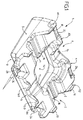
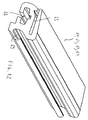
同様に、本発明は、主として一つの下部壁3、一つの上部壁4および四つの側壁5、6、7、8を構成する気密なプラスチック製ケーシング2で構成された光起電力パネル支持装置1において、前記プラスチック製ケーシングの前記上部表面4上に光起電力パネルの維持手段を有する装置に関する。
Similarly, the present invention relates to a photovoltaic panel support device 1 mainly composed of an airtight
前記維持手段により、前記プラスチック製ケーシング2の上部壁4に支えられた、前記上部壁4の平面に対して平行な、光起電力パネルの安定した位置づけが可能となる。パネルの表面またはフレームは、上部壁上に直接支えられてもよいし、あるいは維持手段を介して間接的に支えられてもよい。
The maintenance means enables stable positioning of the photovoltaic panel supported by the
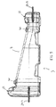
気密なプラスチック製ケーシング2は、それがフロートを構成できるようにする一定の空気体積を閉じ込めることができる。任意には、このケーシングは、特にネジ留めされる栓により閉鎖された開口部200を有することができる。この栓により、任意には、前記プラスチック製ケージング2の内部容積を部分的に充填することが可能となる。
The airtight
この配置により、前記プラスチック製ケーシング2がフロートとして使用される場合、浮力条件を変更し、さらには、風に対する装置の感応性を低減させることが可能になる。装置が、地面上または硬い表面上で使用される場合、開口部は、例えば砂をケーシングに充填して装置にバラストを付加することを可能にする。
With this arrangement, when the
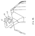
一実施形態によると、前記維持手段は、装置1のプラスチック製ケーシング2と明らかに異なる固定用要素で構成されている。例えば、特に図12〜16に示されている実施例によると、前記維持手段は、前記プラスチック製ケーシング2に固定されたエラストマー製の二つの固定用形材61、62;63;64を含み、前記二つの固定用形材61、62;63;64は互いに平行に延在している。
According to one embodiment, the maintenance means are constituted by fixing elements that are distinctly different from the
各々の固定用形材は、フレーム付き光起電力パネルのフレームCを弾性的に挟持すること、あるいはフレーム無しの光起電力パネルを弾性的に挟持することを目的とする長手方向スリット65を有している。
Each fixing profile has a
有利には、二つの固定用形材61、62または63、64の前記長手方向スリット65は、光起電力パネルの平面に対して平行な同じ平面に沿って延在していてよく、前記二つの固定用形材61、62;63;64は、光起電力パネルの固定を可能にするような形で互いに離隔されている。
Advantageously, the
有利には、長手方向スリット65はこうして、前記(光起電力パネルまたはそのフレームの)弾性的挟持、および一方では前記固定用形材61、62;63;64のエラストマー材料と他方ではフレーム無しの光起電力パネルPまたはフレーム付きの光起電力パネルPのフレームCとの間の摩擦のみによって光起電力パネルPの移動を阻止する。
Advantageously, the
例えば、図15の実施形態によると、二つの固定用形材63、64は、フレームの二つの相対する縁部C1、C2の弾性的挟持により、フレーム付きパネルの維持を可能にする。このとき、長手方向スリット65は、外側に向かって開放し、フレームの同一平面内の二つの翼をそれぞれに挟持する。この実施形態に関しては、エラストマー製形材63、64がパネルPで覆われ、こうして紫外線から保護されていることが指摘される。
For example, according to the embodiment of FIG. 15, the two fixing
図16に示された別の実施形態によると、二つの固定用形材61、62は、光起電力パネルの二つの縁部の弾性的挟持によりフレーム無しのパネルの維持を可能にする。長手方向スリット65は、内側に向かって開放し、フレーム無しの光起電力パネルの維持を可能にする。
According to another embodiment shown in FIG. 16, the two
二つの固定用形材61、62または63、64は、フレーム付きまたはフレーム無しの光起電力パネルPをその縁部の二つのみにより維持することを可能にしており、パネルPは、特に前記プラスチック製ケーシング2から片持ち状態で前記形材61、62;63;64に対し平行な方向に沿って、前記プラスチック製ケーシング2の両側で特に形材から任意にはみ出すことができる。
The two fixing
有利には、長手方向スリット65の深さは、形材に対し垂直でかつパネルの平面に対し平行な方向に沿って、余剰のある状態であってよく、これにより装置のケーシングおよび/またはパネルの膨張現象を考慮に入れられるようになり、こうして、パネルおよびそのフレームが、二つの固定用形材の底面に対し当接することが回避される。
Advantageously, the depth of the
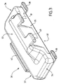
有利には、示された一実施形態によると、各々のエラストマー製固定用形材61、62;63;64は、装置1の前記プラスチック製ケーシング2の固定用リブ66;67に相補的な形状をもつ長手方向溝68を含むことができる。固定用形材は、このとき、エラストマー製固定用形材の前記相補的溝68の中に固定用リブを入り込ませることによって前記プラスチック製ケーシング2と一体化される。
Advantageously, according to one embodiment shown, each
固定用リブ66;67は、T字形断面、錠前の穴(台形と組み合わされた円板)の形状の断面、または、前記固定用リブにおけるエラストマー製固定用形材の引き抜きによる離脱を許容しない他のあらゆる形状の断面を呈していてよい。
The fixing
プラスチック製ケーシング2のこの固定用リブ66、67は、好ましくは、装置1の前記プラスチック製ケーシング2と一続きになっており、特に回転成形技術さらには押出ブロー成形技術による前記プラスチック製ケーシング2の成形の際に得ることができる。
The fixing
同様に、装置のプラスチック製ケーシングに対する各エラストマー製固定用形材の固定も、相補的断面を有する長手方向溝68の中に固定用リブ66;67を入り込ませることによって単純にかつ工具無しで実施され得る。リブの方向に沿ったケーシングに対する固定用形材の維持は、単純に形材のエラストマー材料と固定用リブのプラスチック材料との間の摩擦により得られる。
Similarly, the fixing of each elastomeric fixing profile to the plastic casing of the device is performed simply and without tools by inserting the fixing
任意には、エラストマー製固定用形材61、62または63、64は、さらに、長手方向切込み69を含んでいてよく、その内側に電気ケーブルを通過させるようになっている。
Optionally, the
別の実施形態によると、前記維持用手段は、前記プラスチック製ケーシングと一続きになったプラスチック製要素で構成されている。 According to another embodiment, the means for maintaining comprises a plastic element connected to the plastic casing.
例えば、前記維持手段は、一方では、前記光起電力パネルPの相対する平行な二つの縁部と滑動的に協働することのできる前記上部表面4上に突出した状態のスライダ手段10、11、12、13と、他方では、ストッパ手段140、150とを含む。
For example, the maintaining means, on the one hand, slide means 10, 11 in a protruding state on the
このようにして、光起電力パネルPは、前記光起電力パネルPが前記ストッパ手段140、150と接触するまで前記スライダ手段10、11、12、13の間で前記上部壁の平面に平行な方向に前記光起電力パネルPを摺動させることによって、前記プラスチック製ケーシング2の上部表面上4に維持可能である。
In this way, the photovoltaic panel P is parallel to the plane of the upper wall between the slider means 10, 11, 12, 13 until the photovoltaic panel P contacts the stopper means 140, 150. By sliding the photovoltaic panel P in the direction, it can be maintained on the
前記維持手段の中にひとたび挿入されたならば、光起電力パネルは、ストッパ手段によって滑動方向で第一の向きに移動が阻止されて、前記ケーシングの上部壁に対しほぼ平行となる。前期第一の向きとは反対の第二の向きでの滑動を阻止するためにロック要素(図示せず)を具備してもよい。例えばロック要素は、前記プラスチック製ケーシング2の壁の内部の二重成形されたナット内に螺入される要素であり得る。ひとたび螺入されたならば、要素は前記第二の向きでの光起電力パネルPのためのストッパを構成する。
Once inserted into the retaining means, the photovoltaic panel is prevented from moving in a sliding direction in the first direction by the stopper means and is substantially parallel to the upper wall of the casing. A locking element (not shown) may be provided to prevent sliding in a second orientation opposite to the first orientation. For example, the locking element can be an element that is screwed into a double molded nut inside the wall of the
パネルの平面に対し垂直な方向へのパネルの移動の阻止は、前記スライダ手段とケーシングの上部壁によって得られる。 Prevention of movement of the panel in a direction perpendicular to the plane of the panel is obtained by the slider means and the upper wall of the casing.
示された一実施形態によると、前記スライダ手段10、11、12、13および前記ストッパ手段140、150は、前記装置1の前記プラスチック製ケーシング2と一続きでプラスチック製要素により構成される。
According to one embodiment shown, the slider means 10, 11, 12, 13 and the stopper means 140, 150 are constituted by a plastic element in series with the
例えば、前記スライダ手段は、互いに平行な前記上部壁4の二つの稜A1、A3のレベルに具備される。前記スライダ手段は、特に数が四つである要素10、11、12、13によって構成される。各要素10、11、12、13は、上部壁4から突出して延在し、光起電力パネルPのエッジを収容することを目的とする溝を形成する。図中では、要素は、数が四つで、二つずつ向かい合っている。
For example, the slider means is provided at the level of two edges A1 and A3 of the
前記ストッパ手段は、前記プラスチック製ケーシング2の上部壁4のもう一つの稜A4の上に構成される。前記ロック要素は場合によっては、A3と印付けされた最後の稜の上に位置している。
The stopper means is constructed on another ridge A4 of the
示された一実施形態によると、前記プラスチック製ケーシング2は、
− 前記光起電力パネルの通気を目的とし、前記上部壁4から前記下部壁3まで前記プラスチック製ケーシング2を貫通するくり抜き部14および/または、
− 上部壁4上で深さ方向に延在し、前記光起電力パネルの通気を目的とし、前記プラスチック製ケーシング2の一つの側壁から前記プラスチック製ケーシングの反対側の側壁まで延在している少なくとも一つの流路15、16、を有する。
According to one embodiment shown, the
A hollow 14 that penetrates the
-Extends in the depth direction on the
例えば、図の例によると、前記プラスチック製ケーシング2は、前記ケーシングの上部表面の20%〜50%にわたって延在する前記くり抜き部14と、前記プラスチック製ケーシング2の上部壁4上で深さ方向の互いに垂直な二本の流路15、16とを有する。
For example, according to the example of the figure, the
流路の一本15は、側壁6から反対側の前記側壁8まで延在し、任意に存在するもう一本の流路16は、もう一つの側壁5から前記反対側の側壁7まで延在する。一本の流路16はさらに、電気ケーブルを通すための一つの溝を深さ方向に有する。
One
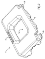
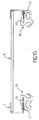
一実施形態によると、プラスチック製ケーシング2の前記下部壁3および上部壁4は、互いに平行でなく、互いに角度αだけ傾斜している。この角度αは、10°〜30°、そして例えば10°〜14°(すなわち12°)の間に含まれていてよい。この角度αの役目は、装置が前記下部壁3を介して水平な表面上に載っている場合に水平との関係において光起電力パネルPを前記同じ角度αだけ傾斜させることにある。10°〜14°の間に含まれるこのような角度αは、雨水の流れによるパネルPの自浄作用と最小限に抑えられた風荷重の間の折衷案を示す。
According to one embodiment, the
例えば図2の実施形態による場合、つまり装置1が前記下部壁3を介して水平な表面上に載っている場合、プラスチック製ケーシング2の上部壁4は、一方では水平との関係において前記角度αだけ各々傾斜し互いに平行で、そのレベルにスライダ手段10、11、12、13が具備されている二つの稜A1、A2と;他方では、互いに平行で、各々水平に対して平行で、そのうち一方のA3がより高いレベルにあって光起電力パネルPの導入を許容し、他方のA4がより低いレベルにあって前記ストッパ手段14、15を有している二つの稜A3、A4とを有している。この実施形態によると、装置の自然な勾配は、重力の作用下でストッパ手段140、150の方向にパネルPを拘束する。
For example, according to the embodiment of FIG. 2, ie when the device 1 rests on a horizontal surface via the
図8に示されたもう一つの例によると、装置1が前記下部壁3を介して水平な表面上に載っている場合、プラスチック製ケーシング2の上部壁4は、一方では、水平との関係において前記角度αだけ各々傾斜し互いに平行である二つの稜A1、A2と;他方では、互いに平行で、各々水平に対して平行で、そのうち一方のA3がより高いレベルにあってこのレベルに沿ってT字形のリブ67が具備され、他方のA4がより低いレベルにあってT字形のもう一つのリブ66を有している二つの稜A3、A4と;を有している。図1〜5に示されているように、パネル支持装置1は、前記光起電力パネルPの外形寸法にほぼ等しい外形寸法を有する。特に図7に示されているもう一つの例によると、パネル支持装置1とパネルPは異なる外形寸法を有することができる。
According to another example shown in FIG. 8, when the device 1 rests on a horizontal surface via the
一実施形態によると、前記プラスチック製ケーシング2は、それぞれ前記側壁5、6、7、8の間に位置する前記プラスチック製ケーシング2の四つのコーナーの部位で突出した固定用耳部201を有することができる。
According to one embodiment, the
その上、プラスチック製ケーシング2の側壁5、6、7、8のうち特に相対する少なくとも二つの側壁5、7は、凹形形状を有していてよく、各々の前記壁5また7は内部に向かって曲げられて、波の衝撃を減衰させるようになっており、こうして光起電池上への水の跳ねは回避される。
In addition, at least two of the
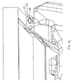
本発明は同様に、本発明に係る光起電力パネルの支持装置1と連結用要素30とを組立てた結果として得られる光起電力パネル支持システム50にも関する。連結用要素30は、本発明に係る少なくとも二つの支持装置を連結することができる。
The invention likewise relates to a photovoltaic
各連結用要素は、気密なプラスチック製ケーシング31により主に構成されており、前記連結用要素の前記プラスチック製ケーシング31は、一つの下部壁32、一つの上部壁33および四つの側壁34、35、36、37を構成し、前記システムは、本発明に係る前記装置1と前記連結用要素30を互いに組立てるための固定用手段を有している。
Each connecting element is mainly constituted by an airtight
前記プラスチック製ケーシング31は、空気体積を閉じ込めることのできる内部容積を有し、前記連結用要素の浮動性の確保を可能にしている。このプラスチック製ケーシング31は、浮動性条件を変更するか、さらには装置にバラストを付加するために、栓により閉鎖された一つの開口部301を有することができる。
The
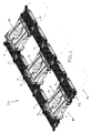
このプラスチック製ケーシング31は、回転成形あるいはブロー押出成形技術によって製造可能である。例えば、前記システム50は、本発明に係る光起電力パネル支持装置1の少なくとも二本の列R1、R2を有している。各列は、特にその側壁5、7を介して並んで配置された装置で構成されている。
The
装置1の前記2本の列R1、R2は、ユーザーのための保守用通路を構成することのできるそれらの側壁34、36を介して並んで配置された連結用要素30の列R3を用いて維持される。前記連結用要素の上部壁33は、この表面が踏みつけられた場合に過度に滑りやすくないようにするため、平滑ではなく、特にエンボス加工され線条の入った状態を呈することができる。
The two rows R1, R2 of the device 1 use a row R3 of connecting
連結用要素30の列R3は、光起電力パネルの二本の列R1、R2を互いに離隔できる一本の間置列であり、列R1のパネルが連続する列R2のパネル上に日陰をつくることがないようにしている。
The row R3 of the connecting
一実施形態によると、固定用手段は、パネル支持装置1のプラスチック製ケーシング2の前記固定用耳部201、ならびに連結用要素30のプラスチック製ケーシング31の固定用耳部301、ならびに留めピン(図示せず)を含み、各留めピンは、組立てをロックすることを確保するために対面させられた二つ、さらには三つまたは四つの耳部を同時に貫通するようになっている。
According to one embodiment, the fixing means include the fixing
一実施形態によると、連結用要素31は、ほぼ直方体の形をしており、その四つのコーナー301に四つの固定用耳部を含む。平行六面体の長辺は、装置のケーシング2の側壁のうちの二つ6、8の長さ方向の寸法にほぼ等しい寸法を有する。
According to one embodiment, the connecting
同一の列R3に属する連続する二つの連結用要素30は、特にそれらの短辺で並んでおり、特に四つの耳部と二つずつ対面させることによって互いに固定される。
Two consecutive connecting
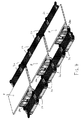
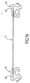
図6に非限定的に示されている一実施形態によると、同一の列R1に属する連続する二つの支持装置1は、二つの装置1のスペーサとして作用する一つの連結用要素30、さらには平行な二つの連結用要素30を用いて互いに遠位に離隔されてよい。同様に、図6の場合、列R3上で、二つの連結用要素30のうちの一つが装置1のスペーサとして作用することができる。
According to one embodiment, which is shown in a non-limiting manner in FIG. 6, two consecutive support devices 1 belonging to the same row R1 have one connecting
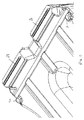
別の実施形態によると、固定用手段は、本発明に係る各支持装置1と各連結用要素30間で互いに係合し合うクリッピング手段で構成され得る。有利には、前記クリッピング手段は、本発明に係る前記装置1の前記プラスチック製ケーシング2と一続きになった第一のプラスチック製要素23、24、25、26、27、28、29と、前記連結用要素30の前記プラスチック製ケーシング31と一続きになった第二のプラスチック製要素38、39、40、41、42で構成されている。
According to another embodiment, the fixing means may be constituted by clipping means that engage each other between each support device 1 and each connecting
例えば、前記第一のプラスチック製要素23、24、25、26、27、28、29は、装置のプラスチック製ケーシング2の二つの側壁6、8の部位に形成される。前記第二のプラスチック製要素38、39、40、41、42は、前記連結用要素30のプラスチック製ケーシング31の二つの側壁35、37の部位で形成される。
For example, the first
組立てに際して、前記連結用要素30は、本発明に係る二つの支持装置1にオーバーラップして配置され、前記二つの隣接する装置1は、同一の列R1に属している。このとき、前記連結用要素は、前記固定用手段を介して前記二つの隣接する装置に固定される。
During assembly, the connecting
図4に示されているように、前記連結用要素30の側壁35の二つのプラスチック製雄部分41、39は、支持装置1の側壁6の雌部分25、27内に強制的に嵌合し、前記連結用要素30の側壁35の二つのプラスチック製雄部分38、40は、隣接する装置1の側壁6の部分26、27内に嵌合する。
As shown in FIG. 4, the two plastic
前記連結用要素30のもう一方の側で、前記連結用要素30の側壁37の雄部分42は、連続する列の装置1の側壁8の雌部分23内および同じ列上の隣接する装置1の側壁8の雌部分24内に強制的に嵌合する。
On the other side of the connecting
水上で利用する場合、浮動式システム50は、適応されたあらゆる手段、例えば水底に固定された定着用ケーブルさらには定着用杭を用いて、水底に定着させることができる。
When used on water, the floating
このようなシステム50および/または装置1は同様に、不安定な地盤、例えばゴミ廃棄場の地盤、冠水しやすい地帯の地面、屋根などの上に太陽光発電設備を実現するためにも応用される。
Such a
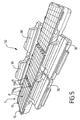
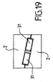
装置1のプラスチック製ケーシング2および連結用要素30のプラスチック製ケーシング31は、図7〜18の実施形態によると、輸送の際に、かつ図19に示されているように、二個ずつ組立てられて、容易に輸送可能なほぼ平行六面体の一つのブロックを形成することができる。組立ては、装置1の二つのプラスチック製ケーシング2および連結用要素の二つのプラスチック製ケーシング31の嵌合によって構成され、後者は二つのプラスチック製ケーシング2の間にサンドイッチ状に取込まれている。このために、ケーシング2の前記上部4の二つの壁は、互いに向かって回転させられている。装置1のケーシング2の上部壁4上にあり、連結用要素30のプラスチック製ケーシング31の相補的キャビティ71(図17)と係合することを目的とする突起70(図8)を用いて、組立ての維持を容易にすることができる。装置1のケーシングの下部壁3上の互いに平行な二つの大きな溝73は、ブロック(すなわち三枚のパレット)の下にフォークリフトの二本のアームを通過させること、さらには溝73に沿って通過する一つまたは複数のタイを用いた組立ての輪掛けを容易にすることができるようにしている。
The
当然のことながら、当業者であれば、以下のクレームに定義されている本発明の枠から逸脱することなく、他の実施形態を企図し得るはずである。 Of course, those skilled in the art could contemplate other embodiments without departing from the scope of the invention as defined in the following claims.
1 パネル支持装置
2 プラスチック製ケーシング
3 下部壁
4 上部壁
5、6、7、8 側壁
10、11、12、13 スライダ手段
140、150 ストッパ手段
P 光起電力パネル
A1、A2、A3、A4 稜
14 くり抜き部
15、16 流路
30 連結用要素
31 プラスチック製ケーシング
32 下部壁
33 上部壁
34、35、36、37 側壁
23、24、25、26、27、28、29 第一のプラスチック製要素
38、39、40、41、42 第二のプラスチック製要素
50 光起電力パネルの支持システム
61、62、63、64 固定用形材
65 長手方向スリット
66、67 固定用リブ
68 溝
69 切込み
70 突起
71 相補的キャビティ
73 溝
200 開口部
201 固定用耳部
300 開口部
301 固定用耳部
DESCRIPTION OF SYMBOLS 1
Claims (18)
前記プラスチック製ケーシング(2)が、
− 前記光起電力パネルの通気を目的とし、前記上部壁(4)から前記下部壁(3)まで前記プラスチック製ケーシング(2)を貫通するくり抜き部(14)を有し、
前記維持手段が前記プラスチック製ケーシング(2)に固定されたエラストマー製の二つの固定用形材(61、62;63;64)を含み、前記二つの固定用形材(61、62;63;64)が互いに平行に延在し、各々の固定用形材が、フレーム付き光起電力パネルのフレーム(C)を挟持することを目的とする、あるいはフレーム無しの光起電力パネルを挟持することを目的とする長手方向スリット(65)を有し、二つの固定用形材の前記長手方向スリット(65)が光起電力パネルの平面に対して平行な同じ平面に沿って延在しており、前記二つの固定用形材(61、62;63;64)が、フレームの二つの相対する縁部(C1、C2)の挟持によるフレーム付き光起電力パネルの固定あるいは光起電力パネルの二つの縁部の挟持によるフレーム無しの光起電力パネルの固定を可能にするような形で互いに離隔されている、光起電力支持装置。 Modular system mainly composed of an airtight single plastic casing (2) which constitutes one lower wall (3), one upper wall (4) and four side walls (5, 6, 7, 8) A photovoltaic panel support device (1) as an element, wherein the plastic casing (2) is capable of confining a certain volume of air that allows it to constitute a float. The panel support device has a photovoltaic panel maintenance means on the upper wall (4) of the plastic casing,
The plastic casing (2) is
-For the ventilation of the photovoltaic panel, with a cutout (14) that penetrates the plastic casing (2) from the upper wall (4) to the lower wall (3);
The retaining means comprises two fixing profiles (61, 62; 63; 64) made of elastomer fixed to the plastic casing (2), the two fixing profiles (61, 62; 63; 64) extend in parallel to each other, and each fixing member is intended to sandwich a frame (C) of a photovoltaic panel with a frame, or sandwich a photovoltaic panel without a frame The longitudinal slits (65) of the two fixing profiles extend along the same plane parallel to the plane of the photovoltaic panel. The two fixing profiles (61, 62; 63; 64) are used for fixing a photovoltaic panel with a frame by sandwiching two opposing edges (C1, C2) of the frame or for two photovoltaic panels. Nipping two edges According are spaced apart from each other in such a way as to allow the fixing of the photovoltaic panel without frame, photovoltaic supporting device.
− 上部表面(4)上で深さ方向に延在し、前記光起電力パネルの通気を目的とし、前記プラスチック製ケーシング(2)の一つの側壁から前記プラスチック製ケーシングの反対側の側壁まで延在している少なくとも一つの流路(15、16)、
を有する、請求項1または2に記載の装置。 The plastic casing (2) is
-Extending in the depth direction on the upper surface (4) and for the purpose of venting the photovoltaic panel, extending from one side wall of the plastic casing (2) to the opposite side wall of the plastic casing; At least one channel (15, 16) present,
The device according to claim 1, comprising:
前記プラスチック製ケーシング(2)が、
− 前記光起電力パネルの通気を目的とし、前記上部壁(4)から前記下部壁(3)まで前記プラスチック製ケーシング(2)を貫通するくり抜き部(14)を有し、
前記プラスチック製ケーシング(2)が、
− 上部表面(4)上で深さ方向に延在し、前記光起電力パネルの通気を目的とし、前記プラスチック製ケーシング(2)の一つの側壁から前記プラスチック製ケーシングの反対側の側壁まで延在している少なくとも一つの流路(15、16)、
を有する、光起電力支持装置。 Modular system mainly composed of an airtight single plastic casing (2) which constitutes one lower wall (3), one upper wall (4) and four side walls (5, 6, 7, 8) A photovoltaic panel support device (1) as an element, wherein the plastic casing (2) is capable of confining a certain volume of air that allows it to constitute a float. The panel support device has a photovoltaic panel maintenance means on the upper wall (4) of the plastic casing,
The plastic casing (2) is
-For the ventilation of the photovoltaic panel, with a cutout (14) that penetrates the plastic casing (2) from the upper wall (4) to the lower wall (3);
The plastic casing (2) is
-Extending in the depth direction on the upper surface (4) and for the purpose of venting the photovoltaic panel, extending from one side wall of the plastic casing (2) to the opposite side wall of the plastic casing; At least one channel (15, 16) present,
A photovoltaic support device.
前記プラスチック製ケーシング(2)が、
− 前記光起電力パネルの通気を目的とし、前記上部壁(4)から前記下部壁(3)まで前記プラスチック製ケーシング(2)を貫通するくり抜き部(14)を有し、
前記下部壁(3)および上部壁(4)が互いに平行でなく、互いに角度αだけ傾斜しており、前記角度αは、例えば12°といったように10°〜30°の間に含まれていて、装置が前記下部壁(3)を介して水平な表面上に載っている場合に水平との関係において光起電力パネルPを前記同じ角度αだけ傾斜させるようになっている、光起電力支持装置。 Modular system mainly composed of an airtight single plastic casing (2) which constitutes one lower wall (3), one upper wall (4) and four side walls (5, 6, 7, 8) A photovoltaic panel support device (1) as an element, wherein the plastic casing (2) is capable of confining a certain volume of air that allows it to constitute a float. The panel support device has a photovoltaic panel maintenance means on the upper wall (4) of the plastic casing,
The plastic casing (2) is
-For the ventilation of the photovoltaic panel, with a cutout (14) that penetrates the plastic casing (2) from the upper wall (4) to the lower wall (3);
The lower wall (3) and the upper wall (4) are not parallel to each other and are inclined with respect to each other by an angle α, and the angle α is included between 10 ° and 30 °, for example, 12 °. The photovoltaic support, which is adapted to tilt the photovoltaic panel P by the same angle α in relation to the horizontal when the device rests on a horizontal surface via the lower wall (3) apparatus.
前記二つの支持装置(1)を離隔する前記二つの連結用要素(30)が、前記二つの離隔された支持装置(1)の間に空間を形成し、前記パネルのはみ出す部分が、前記空間の上に延在する、請求項14に記載のシステム。 Two consecutive supporting devices (1) belonging to the same row (R1) are arranged in two interposition rows (so that the photovoltaic panel is provided in a form protruding from the plastic casing of the supporting device (1). R3) separated from each other by using two parallel connecting elements (30) belonging to R3)
The two connecting elements (30) separating the two support devices (1) form a space between the two spaced support devices (1), and the protruding portion of the panel is the space. 15. The system according to claim 14, wherein the system extends above.
For the realization of floating solar power generation equipment, system utilization according to any one of claims 1 to 1 0 in any apparatus according to one or claims 12 to 17.
Applications Claiming Priority (3)
| Application Number | Priority Date | Filing Date | Title |
|---|---|---|---|
| FR1101189A FR2974163B1 (en) | 2011-04-15 | 2011-04-15 | PANEL SUPPORT DEVICE |
| FR1101189 | 2011-04-15 | ||
| PCT/EP2012/056425 WO2012139998A2 (en) | 2011-04-15 | 2012-04-10 | Panel supporting device |
Related Child Applications (1)
| Application Number | Title | Priority Date | Filing Date |
|---|---|---|---|
| JP2017073787A Division JP6478423B2 (en) | 2011-04-15 | 2017-04-03 | Panel support device |
Publications (2)
| Publication Number | Publication Date |
|---|---|
| JP2014511043A JP2014511043A (en) | 2014-05-01 |
| JP6329068B2 true JP6329068B2 (en) | 2018-05-23 |
Family
ID=45974320
Family Applications (3)
| Application Number | Title | Priority Date | Filing Date |
|---|---|---|---|
| JP2014504276A Expired - Fee Related JP6329068B2 (en) | 2011-04-15 | 2012-04-10 | Panel support device |
| JP2017073787A Expired - Fee Related JP6478423B2 (en) | 2011-04-15 | 2017-04-03 | Panel support device |
| JP2018176526A Active JP6833781B2 (en) | 2011-04-15 | 2018-09-20 | Panel support device |
Family Applications After (2)
| Application Number | Title | Priority Date | Filing Date |
|---|---|---|---|
| JP2017073787A Expired - Fee Related JP6478423B2 (en) | 2011-04-15 | 2017-04-03 | Panel support device |
| JP2018176526A Active JP6833781B2 (en) | 2011-04-15 | 2018-09-20 | Panel support device |
Country Status (10)
| Country | Link |
|---|---|
| US (1) | US9132889B2 (en) |
| EP (2) | EP2697574B1 (en) |
| JP (3) | JP6329068B2 (en) |
| KR (2) | KR101954854B1 (en) |
| CN (2) | CN107659248A (en) |
| ES (1) | ES2786631T3 (en) |
| FR (1) | FR2974163B1 (en) |
| HK (1) | HK1257088A1 (en) |
| PT (1) | PT3336447T (en) |
| WO (1) | WO2012139998A2 (en) |
Families Citing this family (78)
| Publication number | Priority date | Publication date | Assignee | Title |
|---|---|---|---|---|
| FR3007581A1 (en) | 2013-06-20 | 2014-12-26 | Innogur Technologies | FLOATING PHOTOVOLTAIC PLATFORM AND INDEPENDENT WATER TREATMENT SYSTEM ASSOCIATED WITH SUCH A PLATFORM |
| KR20150018341A (en) * | 2013-08-09 | 2015-02-23 | 엘에스산전 주식회사 | Supporting Device for Solar Panel |
| CN103560747B (en) * | 2013-11-14 | 2016-03-16 | 英利集团有限公司 | Overwater solar power station |
| FR3014830B1 (en) * | 2013-12-16 | 2017-02-17 | Ciel Et Terre Int | FLOATING DEVICE PHOTOVOLTAIC PANEL SUPPORT |
| JP6468282B2 (en) * | 2014-03-31 | 2019-02-13 | キョーラク株式会社 | Solar panel float connection structure |
| US10396703B2 (en) | 2014-05-16 | 2019-08-27 | Kyoraku Co., Ltd. | Solar panel float and connected member thereof |
| JP6592876B2 (en) * | 2014-05-16 | 2019-10-23 | キョーラク株式会社 | Float connector for solar panels |
| CN204290836U (en) * | 2014-09-29 | 2015-04-22 | 汉能新材料科技有限公司 | A kind of floating carrier |
| WO2016084970A1 (en) * | 2014-11-29 | 2016-06-02 | 京セラ株式会社 | Solar cell device for use on water |
| FR3032263B1 (en) | 2015-02-04 | 2018-09-07 | Ciel Et Terre International | FIXING PANEL WITH ADJUSTABLE ENTRAX |
| KR101739065B1 (en) | 2015-04-13 | 2017-05-23 | 프로텍코리아 주식회사 | Floater for the solar electric power plant constructed on the water |
| CN106301160A (en) * | 2015-05-29 | 2017-01-04 | 汉能新材料科技有限公司 | A kind of Overwater floating carrier |
| USD800055S1 (en) * | 2015-06-11 | 2017-10-17 | Elie Rothschild | Solar panel attachment base |
| CN106357206A (en) * | 2015-07-17 | 2017-01-25 | 汉能新材料科技有限公司 | Photovoltaic module carrier and matrix |
| CN105162399A (en) * | 2015-08-11 | 2015-12-16 | 湖南红太阳新能源科技有限公司 | Floating body module for split type water photovoltaic power generation system |
| AT517997A1 (en) * | 2015-08-21 | 2017-06-15 | Guger Forschungs Gmbh | photovoltaic module |
| WO2017031516A1 (en) * | 2015-08-21 | 2017-03-02 | Guger Forschungs Gmbh | Photovoltaic module |
| CN106487321A (en) * | 2015-09-01 | 2017-03-08 | 汉能新材料科技有限公司 | A kind of photovoltaic module carrier and matrix |
| CN105048958B (en) * | 2015-09-02 | 2017-12-05 | 长江勘测规划设计研究有限责任公司 | A kind of water surface floating solar power system |
| CN105186968A (en) * | 2015-09-23 | 2015-12-23 | 上海旗华码头工程有限公司 | Floating member used for waterborne photovoltaic power station and connection method thereof |
| CN106571327A (en) * | 2015-10-10 | 2017-04-19 | 汉能新材料科技有限公司 | Photovoltaic module carrier and photovoltaic module carrier matrix |
| CN106612100B (en) * | 2015-10-22 | 2024-03-08 | 东君新能源有限公司 | A photovoltaic component carrier and matrix |
| CN105227068B (en) * | 2015-10-28 | 2018-01-19 | 上海箔梧能源有限公司 | Water photovoltaic panel support device |
| CN105356827B (en) * | 2015-11-18 | 2018-07-06 | 丁慈鑫 | The floating structure and its construction technology of a kind of water surface photovoltaic power station |
| WO2017146458A1 (en) * | 2016-02-25 | 2017-08-31 | 홍형의 | Photovoltaic cell module retainer |
| JP6709642B2 (en) * | 2016-03-14 | 2020-06-17 | 株式会社ジェイエスピー | Float for solar panel and its connected body |
| CN105610387B (en) * | 2016-03-21 | 2018-10-16 | 上海旗华水上工程建设股份有限公司 | Photovoltaic system support device |
| CN105703695B (en) * | 2016-03-21 | 2018-01-26 | 上海旗华水上工程建设股份有限公司 | Support structure of photovoltaic system on water |
| DE102016204704A1 (en) | 2016-03-22 | 2017-09-28 | Stefan Schwaderlapp | Floatable carrier system for solar cells |
| US9729101B1 (en) | 2016-04-25 | 2017-08-08 | X Development Llc | Deployment techniques of a floating photovoltaic power generation system |
| CN105958907B (en) * | 2016-05-04 | 2018-12-07 | 青岛迪玛尔海洋工程有限公司 | A kind of water surface floating dynamic formula photovoltaic generating system |
| EP3829054B2 (en) | 2016-05-31 | 2025-05-28 | Ocean Sun AS | Solar power plant |
| NO343405B1 (en) * | 2016-05-31 | 2019-02-25 | Ocean Sun As | Photovoltaic system for offshore deployment |
| US10723422B2 (en) * | 2016-06-29 | 2020-07-28 | Concept Clean Energy, Llc | Photovoltaic array system and method |
| CN120270425A (en) | 2016-06-30 | 2025-07-08 | 京洛株式会社 | Floating plate, floating plate aggregate, and method for setting floating plate aggregate |
| WO2018055471A1 (en) | 2016-09-26 | 2018-03-29 | Solarisfloat, Lta. | Floating module for modular solar panel platforms |
| JP6933795B2 (en) * | 2016-12-27 | 2021-09-08 | キョーラク株式会社 | Float for solar panel |
| CN107054578B (en) * | 2017-02-06 | 2018-06-26 | 长江勘测规划设计研究有限责任公司 | Tilt adjustable plug-in water surface photovoltaic generating system and installation method |
| CN206472079U (en) * | 2017-02-28 | 2017-09-05 | 北京铂阳顶荣光伏科技有限公司 | The photovoltaic system of floating on water surface |
| WO2018221494A1 (en) | 2017-05-31 | 2018-12-06 | キョーラク株式会社 | Float aggregate |
| FR3069741A1 (en) | 2017-07-27 | 2019-02-01 | Ciel Et Terre International | METHOD FOR MANUFACTURING A SUPPORT DEVICE FOR A PHOTOVOLTAIC PANEL |
| JP6666966B2 (en) * | 2017-08-14 | 2020-03-18 | ▲長▼江勘▲測▼▲規▼▲劃▼▲設▼▲計▼研究有限▲責▼任公司 | Independently supported water surface photovoltaic system for discrete operation and maintenance channels and method of installation |
| CN107317544B (en) * | 2017-08-14 | 2023-08-29 | 长江勘测规划设计研究有限责任公司 | Trinity coupling plug-in type water surface photovoltaic power generation unit and power generation system thereof |
| FR3071221B1 (en) | 2017-09-18 | 2020-01-31 | Ciel Et Terre International | EQUIPMENT FOR THE CONSTRUCTION OF A FLOATING PHOTOVOLTAIC INSTALLATION |
| TWI663098B (en) | 2017-11-10 | 2019-06-21 | 財團法人工業技術研究院 | A carrying device and operation method thereof |
| CN108016580B (en) * | 2017-11-30 | 2020-01-21 | 阳光电源股份有限公司 | A photovoltaic floating body and floating body assembly |
| JP7181450B2 (en) | 2018-02-07 | 2022-12-01 | キョーラク株式会社 | float assembly |
| CN208226926U (en) | 2018-05-03 | 2018-12-11 | 阳光电源股份有限公司 | A kind of support device and photovoltaic system of photovoltaic module |
| JP7082283B2 (en) * | 2018-06-25 | 2022-06-08 | キョーラク株式会社 | Structure and its manufacturing method |
| GB2576713B (en) | 2018-08-24 | 2020-09-02 | Ocean Sun As | A solar power plant and method of installing a solar power plant |
| FR3087083B1 (en) | 2018-10-09 | 2020-10-30 | Ciel Et Terre | FLOATING ELECTRONIC DEVICE AND DATA CENTER INCLUDING SUCH A DEVICE |
| KR102167380B1 (en) * | 2018-10-15 | 2020-10-19 | 쏠에코 주식회사 | Support for solar panel and assembly structure of the same |
| FR3088233B1 (en) | 2018-11-08 | 2020-12-11 | Ciel Et Terre Int | PROCESS FOR OBTAINING A FLOATING PHOTOVOLTAIC INSTALLATION |
| FR3088300B1 (en) | 2018-11-08 | 2022-07-29 | Ciel Et Terre Int | FLOATING PHOTOVOLTAIC INSTALLATION WITH REMOVABLE MAINTENANCE WALKWAYS |
| USD1005909S1 (en) * | 2019-09-16 | 2023-11-28 | International Truck Intellectual Property Company, Llc | Pair of panels for a vehicle |
| PL3865784T3 (en) | 2020-02-14 | 2022-12-19 | Esdec B.V. | System and method for mounting a solar panel onto a substantially flat mounting surface |
| CN111645816A (en) * | 2020-04-26 | 2020-09-11 | 绿华能源(福建)有限公司 | A photovoltaic floating power station composed of a U-shaped floating body and a U-shaped floating body |
| CN113824388A (en) * | 2020-06-19 | 2021-12-21 | 苏州阿特斯新能源发展股份有限公司 | Water surface bearing mechanism and photovoltaic power generation system |
| WO2022045893A1 (en) | 2020-08-31 | 2022-03-03 | Profloating B.V. | Method for manufacturing a design of a floating photovoltaic installation |
| CN214138880U (en) | 2020-09-10 | 2021-09-07 | 淮南阳光浮体科技有限公司 | Water floating power station and its carrying device |
| NL2026458B1 (en) * | 2020-09-11 | 2022-05-09 | Profloating B V | Solar float with a self-locking cap |
| FR3116869B3 (en) | 2020-12-01 | 2022-11-18 | Ciel Et Terre Int | Locking device |
| ES2828225A1 (en) * | 2020-12-10 | 2021-05-25 | Baez Cristian Javier Martin | Modular support structure for solar installations (Machine-translation by Google Translate, not legally binding) |
| US12184221B2 (en) | 2021-04-07 | 2024-12-31 | Noria Energy | Floating solar photovoltaic array with on-board energy management system for controlling and powering inflatable support pontoons, water quality, air compression and mooring devices |
| IT202100013262A1 (en) * | 2021-05-21 | 2022-11-21 | Niccons Italy Srl | SUPPORT ELEMENT FOR PHOTOVOLTAIC PANELS AND MODULAR PHOTOVOLTAIC APPARATUS INCLUDING SAID SUPPORT ELEMENT |
| CN113428309A (en) * | 2021-07-30 | 2021-09-24 | 夏尔特拉(上海)新能源科技有限公司 | Float bowl |
| RU2767411C1 (en) | 2021-11-23 | 2022-03-17 | Общество с ограниченной ответственностью "ХелиоРэк" | Floating module for photovoltaic panels |
| IT202200005417A1 (en) * | 2022-03-18 | 2023-09-18 | Conatct Italia srl | Chained assembly system of rows of photovoltaic panels |
| CN114735147B (en) * | 2022-04-07 | 2023-04-21 | 江苏科技大学 | Wind-wave-resistant floating type offshore photovoltaic device |
| ES1294626Y (en) | 2022-07-26 | 2022-12-20 | Isigenere S L | Floating system for photovoltaic panels and floating installation comprising various floating systems for photovoltaic panels |
| WO2024105283A1 (en) | 2022-11-15 | 2024-05-23 | Isigenere, S.L. | Floating system for photovoltaic panels |
| WO2024105285A1 (en) | 2022-11-18 | 2024-05-23 | Isigenere, S.L. | Gangway float for a floating system for photovoltaic panels and floating system for photovoltaic panels |
| FR3143200B1 (en) | 2022-12-09 | 2026-02-13 | Ciel Et Terre Int | Floating solar installation, as well as a maintenance procedure for such a solar installation. |
| WO2024124316A1 (en) * | 2022-12-16 | 2024-06-20 | Sperb Marcelo | Arrangement for a support for attaching a photovoltaic panel |
| NO20230595A1 (en) * | 2023-05-22 | 2024-11-25 | Cyprinus As | A solar panel float unit |
| DE102023002411A1 (en) | 2023-06-14 | 2024-12-19 | Klaus Schuwerk | submersible solar system |
| FR3154977B1 (en) | 2023-11-03 | 2025-10-24 | Ciel Et Terre Int | Floating modular assembly featuring an improved connection system |
| WO2025141560A1 (en) * | 2023-12-25 | 2025-07-03 | Solar Sensei - Investment And Services Ltd. | Floating photovoltaic arrangement |
Family Cites Families (33)
| Publication number | Priority date | Publication date | Assignee | Title |
|---|---|---|---|---|
| JPS5762572A (en) * | 1980-10-03 | 1982-04-15 | Fuji Electric Co Ltd | Installing method for solar battery |
| JPS63126188U (en) * | 1987-02-13 | 1988-08-17 | ||
| JPH0231465A (en) | 1988-07-21 | 1990-02-01 | Sony Corp | Non-volatile memory wafer |
| JPH0472681A (en) | 1990-07-12 | 1992-03-06 | Sanyo Electric Co Ltd | Floating-type solar cell device |
| JPH1121867A (en) * | 1997-06-27 | 1999-01-26 | Maeda Corp | Artificial land, constructing method of artificial land, and extending method of artificial land |
| JPH11128990A (en) * | 1997-10-30 | 1999-05-18 | Shimizu Corp | Water purification device |
| JPH11301578A (en) * | 1998-04-17 | 1999-11-02 | Sanyo Electric Co Ltd | Floating device |
| JP3069021U (en) * | 1999-08-05 | 2000-05-30 | 浩三 湯原 | Water surface solar power system |
| JP2001254494A (en) | 2000-03-10 | 2001-09-21 | Kanegafuchi Chem Ind Co Ltd | Installation method of solar cell module, solar cell unit and solar cell panel |
| JP2002173083A (en) * | 2000-12-05 | 2002-06-18 | Shin Kobe Electric Mach Co Ltd | Float for mounting solar cell and solar cell device |
| JP2003229593A (en) * | 2002-01-31 | 2003-08-15 | Jfe Steel Kk | Photovoltaic power generator for water installation and its connection structure |
| JP2003327195A (en) * | 2002-05-09 | 2003-11-19 | Port & Airport Research Institute | Floating structure |
| JP2004063497A (en) | 2002-07-24 | 2004-02-26 | Hitachi Chem Co Ltd | Water float made of resin for solar cells |
| JP2004071965A (en) | 2002-08-08 | 2004-03-04 | Sharp Corp | Waterborne solar cell module, waterborne solar cell power supply, and method of using waterborne solar cell module |
| JP2004228263A (en) * | 2003-01-22 | 2004-08-12 | Takiron Co Ltd | Wrap-cover panel device |
| US20080029148A1 (en) * | 2004-10-29 | 2008-02-07 | Thompson Daniel S | Floating support structure for a solar panel array |
| JP2007107345A (en) * | 2005-10-17 | 2007-04-26 | Nippon Tetsupan Kk | Solar power enclosure |
| US20070234945A1 (en) * | 2005-11-28 | 2007-10-11 | Khouri Bruce M | Photovoltaic floatation device |
| NL1031317C2 (en) * | 2006-03-07 | 2007-09-10 | Ubbink Econergy Solar Gmbh | Support for solar panel. |
| JP5058178B2 (en) | 2007-01-19 | 2012-10-24 | 株式会社クレハ環境 | Anti-floating water float |
| JP2010532088A (en) | 2007-06-19 | 2010-09-30 | ビーピー・コーポレーション・ノース・アメリカ・インコーポレーテッド | Solar module with solar panel mounting frame |
| NL2001092C2 (en) * | 2007-12-14 | 2009-06-16 | Renusol Gmbh | Carrier for a solar panel. |
| JP2009202697A (en) * | 2008-02-27 | 2009-09-10 | Kyocera Corp | Photovoltaic power generation device |
| KR100975212B1 (en) * | 2008-08-07 | 2010-08-10 | 주형중 | Floating Solar Panel Installation Structure |
| DE102008055627A1 (en) * | 2008-11-03 | 2010-05-06 | Bauer Kunststofftechnik Gmbh | Device for arranging solar collectors and/or solar modules e.g. photovoltaic modules, utilized for producing electricity, has ventilation section provided in each side wall at side turned away from base, where device is made of plastic |
| IT1392792B1 (en) * | 2008-12-02 | 2012-03-23 | Daiet S R L | FLOATING PHOTOVOLTAIC SYSTEM |
| EP2401560A2 (en) * | 2009-02-26 | 2012-01-04 | Ecostal Sprl | Photovoltaic panel supporting device |
| DE102009019548A1 (en) * | 2009-04-30 | 2010-11-04 | Wilhelm Ötting Kunststoffverformung GmbH & Co. KG | Assembling module for assembling solar collector at e.g. flat roof of house, has fastening devices displaced at holding rail and fixed in desired position, where holding rails are attached at upper side of columns |
| EP2443665A4 (en) * | 2009-06-17 | 2012-11-14 | Water Innovations Power And Technology Holdings Pty Ltd | Waterborn solar generators |
| CH701870A2 (en) * | 2009-09-17 | 2011-03-31 | Tnc Consulting Ag | Floating photovoltaic arrangement. |
| DE202010001518U1 (en) * | 2010-01-28 | 2010-04-22 | Ralos Vertriebs Gmbh | Device for receiving a solar module, in particular photovoltaic module |
| WO2011094803A1 (en) * | 2010-02-02 | 2011-08-11 | C & L Pastoral Company Pty Ltd | Floatation device for solar panels |
| CN201639519U (en) * | 2010-04-07 | 2010-11-17 | 山东力诺太阳能电力工程有限公司 | Solar panel installing support frame |
-
2011
- 2011-04-15 FR FR1101189A patent/FR2974163B1/en not_active Expired - Fee Related
-
2012
- 2012-04-10 CN CN201710874999.6A patent/CN107659248A/en active Pending
- 2012-04-10 CN CN201280019626.6A patent/CN103597737B/en active Active
- 2012-04-10 JP JP2014504276A patent/JP6329068B2/en not_active Expired - Fee Related
- 2012-04-10 EP EP12714668.6A patent/EP2697574B1/en not_active Not-in-force
- 2012-04-10 EP EP18154764.7A patent/EP3336447B1/en active Active
- 2012-04-10 KR KR1020137028379A patent/KR101954854B1/en not_active Expired - Fee Related
- 2012-04-10 KR KR1020187017266A patent/KR101961712B1/en not_active Expired - Fee Related
- 2012-04-10 PT PT181547647T patent/PT3336447T/en unknown
- 2012-04-10 US US14/111,826 patent/US9132889B2/en active Active
- 2012-04-10 WO PCT/EP2012/056425 patent/WO2012139998A2/en not_active Ceased
- 2012-04-10 ES ES18154764T patent/ES2786631T3/en active Active
-
2017
- 2017-04-03 JP JP2017073787A patent/JP6478423B2/en not_active Expired - Fee Related
-
2018
- 2018-09-20 JP JP2018176526A patent/JP6833781B2/en active Active
- 2018-12-20 HK HK18116336.9A patent/HK1257088A1/en unknown
Also Published As
| Publication number | Publication date |
|---|---|
| ES2786631T3 (en) | 2020-10-13 |
| EP3336447A1 (en) | 2018-06-20 |
| CN103597737B (en) | 2017-09-19 |
| HK1257088A1 (en) | 2019-10-11 |
| CN103597737A (en) | 2014-02-19 |
| KR101954854B1 (en) | 2019-03-06 |
| JP2019022443A (en) | 2019-02-07 |
| FR2974163A1 (en) | 2012-10-19 |
| KR101961712B1 (en) | 2019-03-25 |
| KR20140037068A (en) | 2014-03-26 |
| KR20180072849A (en) | 2018-06-29 |
| FR2974163B1 (en) | 2018-06-22 |
| PT3336447T (en) | 2020-04-24 |
| US9132889B2 (en) | 2015-09-15 |
| CN107659248A (en) | 2018-02-02 |
| EP2697574A2 (en) | 2014-02-19 |
| JP2017163830A (en) | 2017-09-14 |
| JP6833781B2 (en) | 2021-02-24 |
| EP3336447B1 (en) | 2020-01-22 |
| WO2012139998A2 (en) | 2012-10-18 |
| JP6478423B2 (en) | 2019-03-06 |
| JP2014511043A (en) | 2014-05-01 |
| WO2012139998A3 (en) | 2013-07-04 |
| US20140224165A1 (en) | 2014-08-14 |
| EP2697574B1 (en) | 2018-04-18 |
Similar Documents
| Publication | Publication Date | Title |
|---|---|---|
| JP6329068B2 (en) | Panel support device | |
| US8272189B2 (en) | PV module frame, PV module and installation system thereof | |
| EP2884202B1 (en) | Supporting device for solar panel | |
| US7487771B1 (en) | Solar panel frame assembly and method for forming an array of connected and framed solar panels | |
| JP4209451B1 (en) | Solar cell module | |
| KR101902964B1 (en) | Solar power generation structure of floating type | |
| JP2010248801A (en) | Connecting member | |
| KR101067951B1 (en) | Solar module frame | |
| JP2009057757A (en) | Solar cell module | |
| WO2010124529A1 (en) | Pv module frame, pv module and installation system thereof | |
| KR20180012301A (en) | Electrical connection device for a photovoltaic system | |
| KR102287955B1 (en) | Finishing panel for exterior wall and finishing structure for exterior wall using the same | |
| JP2005347291A (en) | Solar cell module | |
| KR102117305B1 (en) | Solar power generation structure of floating type | |
| KR101557965B1 (en) | The solar module | |
| KR101138990B1 (en) | Terminal box for solar cell module | |
| CA3022605A1 (en) | Water tight photovoltaic roofing system | |
| KR102258755B1 (en) | Support Structure for Solar Cell Module | |
| JP4146787B2 (en) | Roof mounting structure for solar cell module, solar cell structure, roof mounting method thereof, and module unit replacement method | |
| JP6511269B2 (en) | Roof structure | |
| KR101857739B1 (en) | Solar energy generation assembly for windows and doors | |
| JP6594626B2 (en) | Roof structure | |
| NO20231108A1 (en) | Solar cell wall panel | |
| KR101260503B1 (en) | Water backflow prevention assembly for panel equipped with solar cell module | |
| KR20200126465A (en) | Lightweight prefabricated structures for installation of solar modules |
Legal Events
| Date | Code | Title | Description |
|---|---|---|---|
| A621 | Written request for application examination |
Free format text: JAPANESE INTERMEDIATE CODE: A621 Effective date: 20150324 |
|
| A977 | Report on retrieval |
Free format text: JAPANESE INTERMEDIATE CODE: A971007 Effective date: 20151224 |
|
| A131 | Notification of reasons for refusal |
Free format text: JAPANESE INTERMEDIATE CODE: A131 Effective date: 20160126 |
|
| A521 | Request for written amendment filed |
Free format text: JAPANESE INTERMEDIATE CODE: A523 Effective date: 20160422 |
|
| A131 | Notification of reasons for refusal |
Free format text: JAPANESE INTERMEDIATE CODE: A131 Effective date: 20161004 |
|
| A601 | Written request for extension of time |
Free format text: JAPANESE INTERMEDIATE CODE: A601 Effective date: 20161221 |
|
| A601 | Written request for extension of time |
Free format text: JAPANESE INTERMEDIATE CODE: A601 Effective date: 20170302 |
|
| A521 | Request for written amendment filed |
Free format text: JAPANESE INTERMEDIATE CODE: A523 Effective date: 20170403 |
|
| A131 | Notification of reasons for refusal |
Free format text: JAPANESE INTERMEDIATE CODE: A131 Effective date: 20170912 |
|
| A521 | Request for written amendment filed |
Free format text: JAPANESE INTERMEDIATE CODE: A523 Effective date: 20171211 |
|
| A131 | Notification of reasons for refusal |
Free format text: JAPANESE INTERMEDIATE CODE: A131 Effective date: 20180227 |
|
| A521 | Request for written amendment filed |
Free format text: JAPANESE INTERMEDIATE CODE: A523 Effective date: 20180301 |
|
| TRDD | Decision of grant or rejection written | ||
| A01 | Written decision to grant a patent or to grant a registration (utility model) |
Free format text: JAPANESE INTERMEDIATE CODE: A01 Effective date: 20180320 |
|
| A61 | First payment of annual fees (during grant procedure) |
Free format text: JAPANESE INTERMEDIATE CODE: A61 Effective date: 20180419 |
|
| R150 | Certificate of patent or registration of utility model |
Ref document number: 6329068 Country of ref document: JP Free format text: JAPANESE INTERMEDIATE CODE: R150 |
|
| S531 | Written request for registration of change of domicile |
Free format text: JAPANESE INTERMEDIATE CODE: R313531 |
|
| R350 | Written notification of registration of transfer |
Free format text: JAPANESE INTERMEDIATE CODE: R350 |
|
| RD02 | Notification of acceptance of power of attorney |
Free format text: JAPANESE INTERMEDIATE CODE: R3D02 |
|
| R250 | Receipt of annual fees |
Free format text: JAPANESE INTERMEDIATE CODE: R250 |
|
| LAPS | Cancellation because of no payment of annual fees |