JP6325504B2 - Servo control device having a function of automatically adjusting a learning controller - Google Patents
Servo control device having a function of automatically adjusting a learning controller Download PDFInfo
- Publication number
- JP6325504B2 JP6325504B2 JP2015211940A JP2015211940A JP6325504B2 JP 6325504 B2 JP6325504 B2 JP 6325504B2 JP 2015211940 A JP2015211940 A JP 2015211940A JP 2015211940 A JP2015211940 A JP 2015211940A JP 6325504 B2 JP6325504 B2 JP 6325504B2
- Authority
- JP
- Japan
- Prior art keywords
- evaluation function
- learning
- characteristic
- unit
- learning controller
- Prior art date
- Legal status (The legal status is an assumption and is not a legal conclusion. Google has not performed a legal analysis and makes no representation as to the accuracy of the status listed.)
- Active
Links
Images


Classifications
-
- G—PHYSICS
- G05—CONTROLLING; REGULATING
- G05B—CONTROL OR REGULATING SYSTEMS IN GENERAL; FUNCTIONAL ELEMENTS OF SUCH SYSTEMS; MONITORING OR TESTING ARRANGEMENTS FOR SUCH SYSTEMS OR ELEMENTS
- G05B13/00—Adaptive control systems, i.e. systems automatically adjusting themselves to have a performance which is optimum according to some preassigned criterion
- G05B13/02—Adaptive control systems, i.e. systems automatically adjusting themselves to have a performance which is optimum according to some preassigned criterion electric
- G05B13/04—Adaptive control systems, i.e. systems automatically adjusting themselves to have a performance which is optimum according to some preassigned criterion electric involving the use of models or simulators
- G05B13/042—Adaptive control systems, i.e. systems automatically adjusting themselves to have a performance which is optimum according to some preassigned criterion electric involving the use of models or simulators in which a parameter or coefficient is automatically adjusted to optimise the performance
-
- G—PHYSICS
- G05—CONTROLLING; REGULATING
- G05B—CONTROL OR REGULATING SYSTEMS IN GENERAL; FUNCTIONAL ELEMENTS OF SUCH SYSTEMS; MONITORING OR TESTING ARRANGEMENTS FOR SUCH SYSTEMS OR ELEMENTS
- G05B13/00—Adaptive control systems, i.e. systems automatically adjusting themselves to have a performance which is optimum according to some preassigned criterion
- G05B13/02—Adaptive control systems, i.e. systems automatically adjusting themselves to have a performance which is optimum according to some preassigned criterion electric
- G05B13/0265—Adaptive control systems, i.e. systems automatically adjusting themselves to have a performance which is optimum according to some preassigned criterion electric the criterion being a learning criterion
-
- G—PHYSICS
- G05—CONTROLLING; REGULATING
- G05B—CONTROL OR REGULATING SYSTEMS IN GENERAL; FUNCTIONAL ELEMENTS OF SUCH SYSTEMS; MONITORING OR TESTING ARRANGEMENTS FOR SUCH SYSTEMS OR ELEMENTS
- G05B19/00—Program-control systems
- G05B19/02—Program-control systems electric
- G05B19/18—Numerical control [NC], i.e. automatically operating machines, in particular machine tools, e.g. in a manufacturing environment, so as to execute positioning, movement or co-ordinated operations by means of program data in numerical form
- G05B19/19—Numerical control [NC], i.e. automatically operating machines, in particular machine tools, e.g. in a manufacturing environment, so as to execute positioning, movement or co-ordinated operations by means of program data in numerical form characterised by positioning or contouring control systems, e.g. to control position from one programmed point to another or to control movement along a programmed continuous path
-
- G—PHYSICS
- G05—CONTROLLING; REGULATING
- G05B—CONTROL OR REGULATING SYSTEMS IN GENERAL; FUNCTIONAL ELEMENTS OF SUCH SYSTEMS; MONITORING OR TESTING ARRANGEMENTS FOR SUCH SYSTEMS OR ELEMENTS
- G05B19/00—Program-control systems
- G05B19/02—Program-control systems electric
- G05B19/18—Numerical control [NC], i.e. automatically operating machines, in particular machine tools, e.g. in a manufacturing environment, so as to execute positioning, movement or co-ordinated operations by means of program data in numerical form
- G05B19/402—Numerical control [NC], i.e. automatically operating machines, in particular machine tools, e.g. in a manufacturing environment, so as to execute positioning, movement or co-ordinated operations by means of program data in numerical form characterised by control arrangements for positioning, e.g. centring a tool relative to a hole in the workpiece, additional detection means to correct position
-
- G—PHYSICS
- G06—COMPUTING OR CALCULATING; COUNTING
- G06N—COMPUTING ARRANGEMENTS BASED ON SPECIFIC COMPUTATIONAL MODELS
- G06N20/00—Machine learning
-
- G—PHYSICS
- G05—CONTROLLING; REGULATING
- G05B—CONTROL OR REGULATING SYSTEMS IN GENERAL; FUNCTIONAL ELEMENTS OF SUCH SYSTEMS; MONITORING OR TESTING ARRANGEMENTS FOR SUCH SYSTEMS OR ELEMENTS
- G05B2219/00—Program-control systems
- G05B2219/30—Nc systems
- G05B2219/39—Robotics, robotics to robotics hand
- G05B2219/39352—Feedback error learning, ffw ann compensates torque, feedback from pd to ann
-
- G—PHYSICS
- G05—CONTROLLING; REGULATING
- G05B—CONTROL OR REGULATING SYSTEMS IN GENERAL; FUNCTIONAL ELEMENTS OF SUCH SYSTEMS; MONITORING OR TESTING ARRANGEMENTS FOR SUCH SYSTEMS OR ELEMENTS
- G05B2219/00—Program-control systems
- G05B2219/30—Nc systems
- G05B2219/41—Servomotor, servo controller till figures
- G05B2219/41144—Element used such as low pass filter to cut resonance at non needed regions
-
- G—PHYSICS
- G05—CONTROLLING; REGULATING
- G05B—CONTROL OR REGULATING SYSTEMS IN GENERAL; FUNCTIONAL ELEMENTS OF SUCH SYSTEMS; MONITORING OR TESTING ARRANGEMENTS FOR SUCH SYSTEMS OR ELEMENTS
- G05B2219/00—Program-control systems
- G05B2219/30—Nc systems
- G05B2219/41—Servomotor, servo controller till figures
- G05B2219/41166—Adaptive filter frequency as function of oscillation, rigidity, inertia load
-
- G—PHYSICS
- G05—CONTROLLING; REGULATING
- G05B—CONTROL OR REGULATING SYSTEMS IN GENERAL; FUNCTIONAL ELEMENTS OF SUCH SYSTEMS; MONITORING OR TESTING ARRANGEMENTS FOR SUCH SYSTEMS OR ELEMENTS
- G05B2219/00—Program-control systems
- G05B2219/30—Nc systems
- G05B2219/42—Servomotor, servo controller kind till VSS
- G05B2219/42128—Servo characteristics, drive parameters, during test move
-
- G—PHYSICS
- G05—CONTROLLING; REGULATING
- G05B—CONTROL OR REGULATING SYSTEMS IN GENERAL; FUNCTIONAL ELEMENTS OF SUCH SYSTEMS; MONITORING OR TESTING ARRANGEMENTS FOR SUCH SYSTEMS OR ELEMENTS
- G05B2219/00—Program-control systems
- G05B2219/30—Nc systems
- G05B2219/42—Servomotor, servo controller kind till VSS
- G05B2219/42141—Filter error learning
-
- G—PHYSICS
- G05—CONTROLLING; REGULATING
- G05B—CONTROL OR REGULATING SYSTEMS IN GENERAL; FUNCTIONAL ELEMENTS OF SUCH SYSTEMS; MONITORING OR TESTING ARRANGEMENTS FOR SUCH SYSTEMS OR ELEMENTS
- G05B2219/00—Program-control systems
- G05B2219/30—Nc systems
- G05B2219/50—Machine tool, machine tool null till machine tool work handling
- G05B2219/50281—Adjust tool for tool offset by using an axis parallel to feed axis
Landscapes
- Engineering & Computer Science (AREA)
- Physics & Mathematics (AREA)
- General Physics & Mathematics (AREA)
- Software Systems (AREA)
- Artificial Intelligence (AREA)
- Theoretical Computer Science (AREA)
- Automation & Control Theory (AREA)
- Computer Vision & Pattern Recognition (AREA)
- Evolutionary Computation (AREA)
- Medical Informatics (AREA)
- Human Computer Interaction (AREA)
- Manufacturing & Machinery (AREA)
- Data Mining & Analysis (AREA)
- Computing Systems (AREA)
- General Engineering & Computer Science (AREA)
- Mathematical Physics (AREA)
- Health & Medical Sciences (AREA)
- Feedback Control In General (AREA)
- Control Of Position Or Direction (AREA)
- Numerical Control (AREA)
Description
本発明は、サーボ制御装置に関し、特に、学習制御器の自動調整を行う機能を有するサーボ制御装置に関する。 The present invention relates to a servo control device, and more particularly to a servo control device having a function of automatically adjusting a learning controller.
近年、工作機械では学習制御に関する技術の実用化が進んでいる。学習制御について簡単に説明すると、学習制御はフィードフォワード信号をある同じ動作に対して最適化する制御である。繰り返し同じ動作を行う事により、フィードフォワード信号が更新されて行き、最終的にはある形に落ち着く。その時点で、学習を終了して、学習制御によって得られたフィードフォワード信号を更新せずにそのまま使用する。 In recent years, practical application of learning control technology is progressing in machine tools. Briefly describing the learning control, the learning control is a control for optimizing the feedforward signal for a certain same operation. By repeatedly performing the same operation, the feed forward signal is updated and finally settled in a certain form. At that time, the learning is terminated and the feedforward signal obtained by the learning control is used as it is without being updated.
学習制御を用いた繰返し動作の高精度化の原理が報告されている(例えば、非特許文献1)。非特許文献1においては、評価関数自体の導出も行われている。しかしながら、非特許文献1においてはサーボ系の周波数応答を実測する技術や実験モード解析は行われておらず、ノミナルな特性以上の計算は行われていなかった。学習制御器の構成方法の原則については言及しているものの、具体的な調整則については触れていない。
The principle of increasing the accuracy of repetitive motion using learning control has been reported (for example, Non-Patent Document 1). In
また、学習制御の特性や安定性についても報告されている(例えば、非特許文献2)。しかしながら、非特許文献2には、学習制御器の調整則については言及されていない。
Further, characteristics and stability of learning control have been reported (for example, Non-Patent Document 2). However, Non-Patent
本発明は、実測の基本制御系特性によって得られる、学習制御を含めたサーボ特性を自動調整することが可能なサーボ制御装置を提供することを目的とする。 An object of the present invention is to provide a servo control device capable of automatically adjusting servo characteristics including learning control, which are obtained by actually measured basic control system characteristics.
本発明の一実施例に係るサーボ制御装置は、サーボモータで駆動される送り軸を有する工作機械のサーボ制御装置において、送り軸を所定の同一動作パターンで駆動するための位置指令を作成する位置指令作成部と、送り軸の位置を検出する位置検出部と、位置指令作成部が作成した位置指令値及び位置検出部が検出した位置検出値を取得し、位置指令値と位置検出値との差分である位置偏差を算出する位置偏差取得部と、位置指令作成部、位置検出部、及び位置偏差取得部を含む位置制御ループと、位置偏差取得部から出力された位置偏差の高周波成分を減衰させる帯域制限フィルタと、帯域制限フィルタから出力された位置偏差に対して位相進めを実施する動特性補償要素と、帯域制限フィルタ及び動特性補償要素を含む学習制御器と、位置制御ループへの正弦波掃引を行う正弦波掃引入力部と、正弦波を位置制御ループへ入力したときの位置制御ループの出力から、位置制御ループ入出力信号の利得と位相を推定するための周波数特性算出部と、周波数特性算出部が算出した実測の周波数特性、及び学習制御器の周波数特性に基づいて、学習制御器付きの位置制御特性を示す評価関数を計算する学習制御特性評価関数算出部と、を具備し、学習制御特性評価関数算出部は、評価関数の値に基づいて学習制御器を構成する帯域制限フィルタ及び動特性補償要素の少なくとも一方の構成を変更することを特徴とする。 A servo control device according to an embodiment of the present invention is a servo control device for a machine tool having a feed shaft driven by a servo motor, and a position for creating a position command for driving the feed shaft in a predetermined same operation pattern. The command creation unit, the position detection unit for detecting the position of the feed axis, the position command value created by the position command creation unit and the position detection value detected by the position detection unit are acquired, and the position command value and the position detection value are A position deviation acquisition unit that calculates a position deviation that is a difference, a position control loop including a position command generation unit, a position detection unit, and a position deviation acquisition unit, and a high frequency component of the position deviation output from the position deviation acquisition unit are attenuated A band limit filter to be performed, a dynamic characteristic compensation element for performing phase advance on the positional deviation output from the band limit filter, a learning controller including the band limit filter and the dynamic characteristic compensation element, For estimating the gain and phase of the position control loop input / output signal from the sine wave sweep input section that performs sine wave sweep to the position control loop and the output of the position control loop when the sine wave is input to the position control loop Based on the frequency characteristic calculation unit, the actual frequency characteristic calculated by the frequency characteristic calculation unit, and the frequency characteristic of the learning controller, the learning control characteristic evaluation function calculation that calculates the evaluation function indicating the position control characteristic with the learning controller is calculated. And a learning control characteristic evaluation function calculation unit that changes at least one of a configuration of a band limiting filter and a dynamic characteristic compensation element constituting the learning controller based on a value of the evaluation function. .
本発明の一実施例に係るサーボ制御装置によれば、機械特性を含めて計測した学習制御器つきサーボ制御特性の最適化を行うことにより、オフライン計算での定量的な安定性評価と最適化が可能であるため、学習制御の調整における試行錯誤が不要となるという効果が得られる。 According to the servo control device according to one embodiment of the present invention, by performing optimization of the servo control characteristic with the learning controller measured including the mechanical characteristic, quantitative stability evaluation and optimization in the off-line calculation is performed. Therefore, it is possible to obtain an effect that trial and error in adjusting the learning control is not necessary.
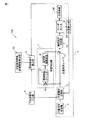
以下、図面を参照して、本発明に係るサーボ制御装置について説明する。図1は、本発明の実施例に係るサーボ制御装置100の構成図である。本発明の実施例に係るサーボ制御装置100は、サーボモータで駆動される送り軸を有する工作機械のサーボ制御装置において、位置指令作成部1と、位置検出部2と、位置偏差取得部3と、位置制御ループ4と、帯域制限フィルタ5と、動特性補償要素6と、学習制御器7と、正弦波掃引入力部8と、周波数特性算出部9と、学習制御特性評価関数算出部10と、を有する。
Hereinafter, a servo control device according to the present invention will be described with reference to the drawings. FIG. 1 is a configuration diagram of a
位置指令作成部1は、伝達機構30を介してサーボモータ20が工作機械の送り軸を所定の同一動作パターンで駆動するための位置指令を作成する。位置指令作成部1が作成した位置指令は位置偏差取得部3に出力される。
The position
位置検出部2は、工作機械の送り軸の位置を検出する。位置検出部2として、エンコーダやレゾルバを用いることができるが、これらには限られない。位置検出部2が検出した送り軸の位置の検出値は位置偏差取得部3に出力される。
The
位置偏差取得部3は、位置指令作成部1が作成した位置指令値及び位置検出部2が検出した位置検出値を取得し、位置指令値と位置検出値との差分である位置偏差を算出する。上記の位置指令作成部1、位置検出部2、及び位置偏差取得部3を含んで位置制御ループ4が構成される。
The position
帯域制限フィルタ5は、位置偏差取得部3から出力された位置偏差の高周波成分を減衰させる。帯域制限フィルタ5は、ある周波数領域における高周波領域の信号をカットするためのローパスフィルタであり、制御系を安定させる効果がある。
The
動特性補償要素6は、帯域制限フィルタ5から出力された位置偏差に対して位相進めを実施する。動特性補償要素6は、ある周波数領域における高周波領域の信号の位相を進ませ、さらにゲインを上げるフィルタであり、制御系の遅れやゲイン低下を補償する効果がある。上記の帯域制限フィルタ5及び動特性補償要素6を含んで学習制御器7が構成される。
The dynamic
正弦波掃引入力部8は、位置制御ループ4への正弦波掃引を行う。例えば、正弦波掃引入力部8は、位置制御ループ4を構成する位置偏差取得部3に対して正弦波からなる外乱を入力するようにしてもよい。ただし、このような例には限られない。
The sine wave
周波数特性算出部9は、正弦波を位置制御ループ4へ入力したときの位置制御ループ4の出力から、位置制御ループ入出力信号の利得と位相を推定する。
The
ここで、周波数特性算出部9は、位置制御ループ4の周波数特性を1つの剛体モード及び少なくとも1つの共振モードによって記述するようにしてもよい。
Here, the frequency
学習制御特性評価関数算出部10は、周波数特性算出部9が算出した実測の周波数特性、及び学習制御器7の周波数特性に基づいて、学習制御器付きの位置制御特性を示す評価関数を計算する。学習制御特性評価関数算出部10は、評価関数の値に基づいて学習制御器7を構成する帯域制限フィルタ5及び動特性補償要素6の少なくとも一方の構成を変更する。評価関数の計算等については後述する。
The learning control characteristic evaluation
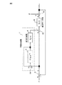
次に、学習制御器7の構成について図2を用いて説明する。位置指令rが減算器11に入力され、減算器11によって位置指令rと位置検出部が検出した実位置yとの差である位置偏差eが算出される。学習制御器7の加算器14は、位置偏差eと、帯域制限フィルタ5に設けられた遅延メモリ(図示せず)に記憶された1パターン周期前の補正量とを加算する。帯域制限フィルタ5は、加算器14の出力をフィルタ処理して補正量を求める。帯域制限フィルタ5は、学習周期Lを用いてF(s)e-sLと表すことができる。動特性補償要素(Gx(s))6は、制御対象の位相遅れやゲイン低下を補償し、学習制御器7は補正量を加算器12に出力する。加算器12は、位置偏差eにこの補正量を加算し、速度指令作成部15において、通常サーボ(位置・速度制御系)のポジションゲインG0(s)を乗じて速度指令を作成する。なお、図2に示した例では、加算器13において速度指令に外乱dが加算される例を示している。
Next, the configuration of the learning controller 7 will be described with reference to FIG. The position command r is input to the subtractor 11, and the subtractor 11 calculates a position deviation e that is a difference between the position command r and the actual position y detected by the position detector. The
次に、学習制御特性評価関数算出部10が、周波数特性算出部9が算出した実測の周波数特性、及び学習制御器7の周波数特性に基づいて、学習制御器付きの位置制御特性を示す評価関数を計算する方法について説明する。
Next, the learning control characteristic evaluation
まず、学習制御器の付加によって、同期的入力のもとで十分に長い時間が経過した後の最終偏差の各角周波数成分が、基本サーボ系の制御偏差に対して最終偏差を非常に小さくすることができることがわかる。また、|F(jω)|≪1となるフィルタの遮断領域では、最終偏差特性は基本サーボ系の応答によって決定される(非特許文献1)。なお、同期的入力とは、学習周期Lに対してr+dが一定値、またはLかLの整数分の一の周期を持つことをいう。 First, with the addition of a learning controller, each angular frequency component of the final deviation after a sufficiently long time under synchronous input makes the final deviation very small with respect to the control deviation of the basic servo system. You can see that In the filter cutoff region where | F (jω) | << 1, the final deviation characteristic is determined by the response of the basic servo system (Non-patent Document 1). The synchronous input means that r + d has a constant value with respect to the learning period L or a period equal to an integer of L or L.
ここで、G(jω)は以下の式(1)で表される。 Here, G (jω) is expressed by the following equation (1).

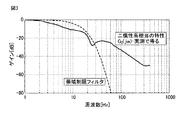
過渡偏差の収束性を表す指標AT(ω)は下記の式(2)で表すことができる。 The index A T (ω) representing the convergence of the transient deviation can be expressed by the following equation (2).
ここで、帯域制限フィルタF(jω)及び通常サーボのゲインG0(jω)の周波数特性を図3に示す。G0(jω)は、二慣性系相当の特性であり、実測で得られる。 Here, the frequency characteristics of the band limiting filter F (jω) and the gain G 0 (jω) of the normal servo are shown in FIG. G 0 (jω) is a characteristic equivalent to a two-inertia system and is obtained by actual measurement.
式(2)より、AT(ω)の値が小さいほど、jω付近の根による過渡応答成分の収束が速い。また、AT=1は応答成分の振幅が一定で収束しないことを示す。 From equation (2), the smaller the value of A T (ω), the faster the convergence of the transient response component by the roots near jω. A T = 1 indicates that the amplitude of the response component is constant and does not converge.
ここで、G0は実測可能であり、Gx,Fは数式で定義可能である。従って、ATは実測ベースで計算可能である。従って、本発明の実施例に係るサーボ制御装置によれば、学習制御器込みでのサーボ制御特性を、機械特性を含めて計測することができる。 Here, G 0 can be measured and G x and F can be defined by mathematical expressions. Therefore, AT can be calculated on an actual measurement basis. Therefore, according to the servo control apparatus according to the embodiment of the present invention, the servo control characteristics including the learning controller can be measured including the mechanical characteristics.
ここで、図4に、本発明の実施例に係るサーボ制御装置の学習制御器における過渡偏差の収束性を表す指標ATの周波数特性の一例を示す。図4において、実線は指標ATを表し、破線は近似曲線(ローレンツ関数)を表す。この近似曲線から評価値を算出する。 Here, FIG. 4 shows an example of the frequency characteristic of the index AT representing the convergence of the transient deviation in the learning controller of the servo controller according to the embodiment of the present invention. In FIG. 4, a solid line represents the index AT, and a broken line represents an approximate curve (Lorentz function). An evaluation value is calculated from this approximate curve.
評価値(評価関数)は、下記の式(3)により算出することができる。
評価関数 = ピーク高さ / 半値幅 (3)
図4において、縦方向の矢印がピーク高さを表し、横方向の矢印が半値幅を示す。評価値が算出されたら、評価値(評価関数)が極小となるように逐次計算で調整を行う。
The evaluation value (evaluation function) can be calculated by the following equation (3).
Evaluation function = Peak height / Half width (3)
In FIG. 4, the vertical arrow represents the peak height, and the horizontal arrow represents the half-value width. When the evaluation value is calculated, adjustment is performed by sequential calculation so that the evaluation value (evaluation function) is minimized.
ここで、学習制御特性評価関数算出部10は、式(3)の評価値が極小となるように、学習制御器7を構成する帯域制限フィルタ5及び動特性補償要素6の少なくとも一方の構成を変更する。図5は、本発明の実施例に係るサーボ制御装置の学習制御器における過渡偏差の収束性を表す指標ATの周波数特性の他の例であって、帯域制限フィルタ5及び動特性補償要素6の構成を変更した後の特性である。図5の近似曲線においては、図4の近似曲線に比べて、ピーク高さが減少し、半値幅が増大しているので、評価関数の値が小さくなっている。このようにして、評価値が極小となるように帯域制限フィルタ5及び動特性補償要素6の構成を変更する。
Here, the learning control characteristic evaluation
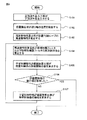
次に、本発明の実施例に係るサーボ制御装置の動作手順について、図6に示したフローチャートを用いて説明する。まず、ステップS101において、正弦波掃引入力部8が位置制御ループ4へ正弦波外乱を入力する。例えば、正弦波掃引入力部8は、位置制御ループ4を構成する位置偏差取得部3に対して正弦波からなる外乱を入力する。
Next, the operation procedure of the servo control apparatus according to the embodiment of the present invention will be described with reference to the flowchart shown in FIG. First, in step S <b> 101, the sine wave
次に、ステップS102において、位置検出部2が工作機械の送り軸の位置を検出する。位置検出部2が検出した送り軸の位置の検出値は位置偏差取得部3に出力される。
Next, in step S102, the
次に、ステップS103において、周波数特性算出部9が、位置制御ループ4の周波数特性を算出する。即ち、周波数特性算出部9が、正弦波を位置制御ループへ入力したときの位置制御ループの出力から、位置制御ループ入出力信号の利得と位相を推定する。
Next, in step S <b> 103, the frequency
次に、ステップS104において、周波数特性算出部9が、帯域制限フィルタ5及び動特性補償要素6の周波数特性を算出する。
Next, in step S104, the frequency
次に、ステップS105において、学習制御特性評価関数算出部10が、位置制御系の評価関数の値を算出する。即ち、学習制御特性評価関数算出部10は、周波数特性算出部9が算出した実測の周波数特性、及び学習制御器7の周波数特性に基づいて、学習制御器付きの位置制御特性を示す評価関数を計算する。評価関数は上述の通り式(3)で表される。
Next, in step S105, the learning control characteristic evaluation
次に、ステップS106において、学習制御特性評価関数算出部10は、評価関数値の極小値を取得したか否かを判断する。極小値を取得していない場合は、ステップS104に戻って、学習制御特性評価関数算出部10は、式(3)の評価値が極小となるように、学習制御器7を構成する帯域制限フィルタ5及び動特性補償要素6の少なくとも一方の構成を変更し、評価関数の計算を継続する。一方、極小値を取得した場合は、処理を終了する。
Next, in step S106, the learning control characteristic evaluation
以上説明したように、本発明の一実施例に係るサーボ制御装置によれば、機械特性を含めて計測した学習制御器つきサーボ制御特性の最適化を行うことにより、オフライン計算での定量的な安定性評価と最適化が可能であるため、学習制御の調整における試行錯誤が不要となるという効果が得られる。 As described above, according to the servo control device according to one embodiment of the present invention, by optimizing the servo control characteristics with the learning controller measured including the mechanical characteristics, the quantitative calculation in the off-line calculation is performed. Since stability evaluation and optimization are possible, the effect that trial and error in adjustment of learning control becomes unnecessary is acquired.
1 位置指令作成部
2 位置検出部
3 位置偏差取得部
4 位置制御ループ
5 帯域制限フィルタ
6 動特性補償要素
7 学習制御器
8 正弦波掃引入力部
9 周波数特性算出部
10 学習制御特性評価関数算出部
DESCRIPTION OF
Claims (1)
送り軸を所定の同一動作パターンで駆動するための位置指令を作成する位置指令作成部と、
送り軸の位置を検出する位置検出部と、
前記位置指令作成部が作成した位置指令値及び前記位置検出部が検出した位置検出値を取得し、位置指令値と位置検出値との差分である位置偏差を算出する位置偏差取得部と、
前記位置指令作成部、前記位置検出部、及び前記位置偏差取得部を含む位置制御ループと、
前記位置偏差取得部から出力された位置偏差の高周波成分を減衰させる帯域制限フィルタと、
前記帯域制限フィルタから出力された位置偏差に対して位相進めを実施する動特性補償要素と、
前記帯域制限フィルタ及び前記動特性補償要素を含む学習制御器と、
前記位置制御ループへの正弦波掃引を行う正弦波掃引入力部と、
正弦波を前記位置制御ループへ入力したときの前記位置制御ループの出力から、位置制御ループ入出力信号の利得と位相を推定するための周波数特性算出部と、
前記周波数特性算出部が算出した実測の周波数特性、及び前記学習制御器の周波数特性に基づいて、学習制御器付きの位置制御特性を示す評価関数を計算する学習制御特性評価関数算出部と、を具備し、
前記学習制御特性評価関数算出部は、評価関数の値に基づいて前記学習制御器を構成する前記帯域制限フィルタ及び前記動特性補償フィルタの少なくとも一方の構成を変更し、
前記学習制御特性評価関数算出部は、評価関数の値が極小となるように前記学習制御器を構成する前記帯域制限フィルタ及び前記動特性補償フィルタの少なくとも一方の調整を行い、
前記評価関数は、前記学習制御器における過渡偏差の収束性を表す指標の周波数特性におけるピーク高さ及び半値幅を用いて、以下の式により算出される、
評価関数 = ピーク高さ / 半値幅
ことを特徴とするサーボ制御装置。 In a servo control device of a machine tool having a feed shaft driven by a servo motor,
A position command creating unit for creating a position command for driving the feed shaft in a predetermined same operation pattern;
A position detector for detecting the position of the feed shaft;
A position deviation acquisition unit that acquires a position command value created by the position command creation unit and a position detection value detected by the position detection unit, and calculates a position deviation that is a difference between the position command value and the position detection value;
A position control loop including the position command generation unit, the position detection unit, and the position deviation acquisition unit;
A band limiting filter for attenuating the high frequency component of the positional deviation output from the positional deviation acquisition unit;
A dynamic characteristic compensation element for performing phase advance on the positional deviation output from the band limiting filter;
A learning controller including the band limiting filter and the dynamic characteristic compensation element;
A sine wave sweep input for performing a sine wave sweep to the position control loop;
A frequency characteristic calculator for estimating a gain and a phase of a position control loop input / output signal from an output of the position control loop when a sine wave is input to the position control loop;
A learning control characteristic evaluation function calculation unit that calculates an evaluation function indicating a position control characteristic with a learning controller based on the actually measured frequency characteristic calculated by the frequency characteristic calculation unit and the frequency characteristic of the learning controller; Equipped,
The learning control characteristic evaluation function calculation unit changes the configuration of at least one of the band limiting filter and the dynamic characteristic compensation filter that configure the learning controller based on the value of the evaluation function,
The learning control characteristic evaluation function calculating unit, have lines at least one of adjustment of the band limiting filter and the dynamic characteristic compensation filter value of the evaluation function constituting the learning controller so that the minimum,
The evaluation function is calculated by the following formula using the peak height and half-value width in the frequency characteristic of the index representing the convergence of the transient deviation in the learning controller.
Servo control device characterized by evaluation function = peak height / half width .
Priority Applications (4)
| Application Number | Priority Date | Filing Date | Title |
|---|---|---|---|
| JP2015211940A JP6325504B2 (en) | 2015-10-28 | 2015-10-28 | Servo control device having a function of automatically adjusting a learning controller |
| DE102016012756.2A DE102016012756B4 (en) | 2015-10-28 | 2016-10-25 | A servo control system having a function for automatically setting a learning control unit |
| US15/335,452 US10281884B2 (en) | 2015-10-28 | 2016-10-27 | Learning controller for automatically adjusting servo control activity |
| CN201610958018.1A CN106647258B (en) | 2015-10-28 | 2016-10-27 | Have the function of carrying out the Servocontrol device of the adjust automatically of learning controller |
Applications Claiming Priority (1)
| Application Number | Priority Date | Filing Date | Title |
|---|---|---|---|
| JP2015211940A JP6325504B2 (en) | 2015-10-28 | 2015-10-28 | Servo control device having a function of automatically adjusting a learning controller |
Publications (2)
| Publication Number | Publication Date |
|---|---|
| JP2017084104A JP2017084104A (en) | 2017-05-18 |
| JP6325504B2 true JP6325504B2 (en) | 2018-05-16 |
Family
ID=58546100
Family Applications (1)
| Application Number | Title | Priority Date | Filing Date |
|---|---|---|---|
| JP2015211940A Active JP6325504B2 (en) | 2015-10-28 | 2015-10-28 | Servo control device having a function of automatically adjusting a learning controller |
Country Status (4)
| Country | Link |
|---|---|
| US (1) | US10281884B2 (en) |
| JP (1) | JP6325504B2 (en) |
| CN (1) | CN106647258B (en) |
| DE (1) | DE102016012756B4 (en) |
Families Citing this family (18)
| Publication number | Priority date | Publication date | Assignee | Title |
|---|---|---|---|---|
| CN108959674B (en) * | 2017-05-27 | 2021-12-07 | 宁波韦尔德斯凯勒智能科技有限公司 | Interactive learning controller and method for compensating repeated interference on position domain |
| CN107846171B (en) * | 2017-09-05 | 2019-10-18 | 北京车和家信息技术有限公司 | The method for controlling frequency conversion and device of motor |
| CN108628166B (en) * | 2018-05-08 | 2020-12-29 | 苏州科技大学 | Optimization method of speed loop gain and integral time of ball screw feed drive system |
| JP7154823B2 (en) | 2018-05-28 | 2022-10-18 | キヤノン株式会社 | Information processing device, robot control device, information processing method and program |
| CN110832422B (en) | 2018-06-14 | 2021-04-16 | 三菱电机株式会社 | Machine learning device, correction parameter adjustment device, and machine learning method |
| JP6784722B2 (en) | 2018-06-28 | 2020-11-11 | ファナック株式会社 | Output device, control device, and evaluation function value output method |
| JP6740290B2 (en) | 2018-07-17 | 2020-08-12 | ファナック株式会社 | Machine learning device, control device, and machine learning method |
| CN111630459A (en) * | 2018-08-01 | 2020-09-04 | 深圳配天智能技术研究院有限公司 | Method, electronic device and storage device for obtaining frequency characteristics of servo system |
| CN108983615B (en) * | 2018-08-17 | 2021-03-30 | 台州学院 | Discrete Bicycle Repetitive Controller Based on Inverse Hyperbolic Sine Law of Attraction |
| JP6856591B2 (en) * | 2018-09-11 | 2021-04-07 | ファナック株式会社 | Control device, CNC device and control method of control device |
| JP6901450B2 (en) * | 2018-10-02 | 2021-07-14 | ファナック株式会社 | Machine learning device, control device and machine learning method |
| JP6849643B2 (en) * | 2018-11-09 | 2021-03-24 | ファナック株式会社 | Output device, control device, and evaluation function and machine learning result output method |
| JP6956122B2 (en) * | 2019-01-24 | 2021-10-27 | ファナック株式会社 | Machine learning systems, controllers and machine learning methods that optimize filter coefficients |
| JP6904994B2 (en) | 2019-02-26 | 2021-07-21 | ファナック株式会社 | Screen creation device and screen creation system |
| JP7021147B2 (en) * | 2019-04-03 | 2022-02-16 | ファナック株式会社 | Motor control device and computer program for motor control |
| JP7000373B2 (en) * | 2019-04-15 | 2022-01-19 | ファナック株式会社 | Machine learning device, control device and machine learning method |
| JP7381751B2 (en) * | 2020-06-09 | 2023-11-15 | ファナック株式会社 | Control support device, control device, and control support method |
| WO2025094330A1 (en) * | 2023-11-01 | 2025-05-08 | ファナック株式会社 | Motor control device and motor control method |
Family Cites Families (32)
| Publication number | Priority date | Publication date | Assignee | Title |
|---|---|---|---|---|
| US3682191A (en) * | 1970-08-10 | 1972-08-08 | Johnson Service Co | Apparatus and method for sensing the position of a surface |
| JPS6453210A (en) * | 1987-05-13 | 1989-03-01 | Hitachi Ltd | Method and device for driving servo system |
| JPH0731529B2 (en) * | 1988-07-29 | 1995-04-10 | オ−クマ株式会社 | Learning control method for numerically controlled machine tools |
| JP2656637B2 (en) * | 1989-11-22 | 1997-09-24 | 株式会社日立製作所 | Process control system and power plant process control system |
| JP2750626B2 (en) * | 1990-03-30 | 1998-05-13 | キヤノン株式会社 | Identification method of viscous friction coefficient of positioning device |
| JPH0535899A (en) * | 1991-08-01 | 1993-02-12 | Toshiba Corp | Frequency characteristic learning device for neural network |
| US5677609A (en) * | 1994-07-28 | 1997-10-14 | National Semiconductor Corporation | Intelligent servomechanism controller |
| US5608843A (en) * | 1994-08-01 | 1997-03-04 | The United States Of America As Represented By The Secretary Of The Air Force | Learning controller with advantage updating algorithm |
| US6097168A (en) * | 1997-08-25 | 2000-08-01 | Toshiba Kikai Kabushiki Kaisha | Position control apparatus and method of the same, numerical control program preparation apparatus and method of the same, and methods of controlling numerical control machine tool |
| US6196773B1 (en) * | 1998-09-08 | 2001-03-06 | Makino Inc. | Tool with control of a fluid axis using reference information from other tool axes |
| JP3552988B2 (en) * | 1999-11-29 | 2004-08-11 | 株式会社安川電機 | Servo control method |
| KR100425461B1 (en) * | 2001-08-29 | 2004-03-30 | 삼성전자주식회사 | Apparatus and method for detecting disc |
| JP2004227163A (en) * | 2003-01-21 | 2004-08-12 | Fanuc Ltd | Servo control device |
| JP2006197726A (en) * | 2005-01-13 | 2006-07-27 | Yaskawa Electric Corp | Positioning control device and positioning control method |
| JP4280241B2 (en) | 2005-02-02 | 2009-06-17 | ファナック株式会社 | Numerical control device having learning control function |
| JP4361071B2 (en) * | 2005-07-08 | 2009-11-11 | ファナック株式会社 | Servo control device |
| JP2008225533A (en) * | 2007-03-08 | 2008-09-25 | Fanuc Ltd | Servo controller |
| JP4830993B2 (en) | 2007-07-11 | 2011-12-07 | 富士電機株式会社 | Degradation detection method for semiconductor device |
| EP2178202A1 (en) | 2007-08-03 | 2010-04-21 | Kabushiki Kaisha Yaskawa Denki | Motor control device and gain adjustment method thereof |
| JP5235707B2 (en) * | 2009-02-03 | 2013-07-10 | キヤノン株式会社 | Control device |
| JP4575508B1 (en) * | 2009-05-20 | 2010-11-04 | ファナック株式会社 | Servo control device for dual position feedback control |
| JP4980453B2 (en) * | 2010-09-06 | 2012-07-18 | ファナック株式会社 | Servo control system for high-precision machining |
| US8853982B2 (en) * | 2010-11-15 | 2014-10-07 | Mitsubishi Electric Corporation | Motor control device |
| JP5302437B1 (en) * | 2012-03-29 | 2013-10-02 | ファナック株式会社 | Control device for injection molding machine having function of adjusting pressure control parameter |
| JP5800750B2 (en) * | 2012-04-11 | 2015-10-28 | ファナック株式会社 | Method for detecting deterioration of movable part of injection molding machine and control device for injection molding machine having function of detecting deterioration of movable part |
| JP5916583B2 (en) * | 2012-10-19 | 2016-05-11 | 株式会社神戸製鋼所 | Weaving control device for articulated robot |
| US9248569B2 (en) * | 2013-11-22 | 2016-02-02 | Brain Corporation | Discrepancy detection apparatus and methods for machine learning |
| US20150283703A1 (en) * | 2014-04-03 | 2015-10-08 | Brain Corporation | Apparatus and methods for remotely controlling robotic devices |
| US9630318B2 (en) * | 2014-10-02 | 2017-04-25 | Brain Corporation | Feature detection apparatus and methods for training of robotic navigation |
| JP6077617B1 (en) * | 2015-09-25 | 2017-02-08 | ファナック株式会社 | Machine tools that generate optimal speed distribution |
| JP6219897B2 (en) * | 2015-09-28 | 2017-10-25 | ファナック株式会社 | Machine tools that generate optimal acceleration / deceleration |
| JP6457563B2 (en) * | 2017-01-24 | 2019-01-23 | ファナック株式会社 | Numerical control device and machine learning device |
-
2015
- 2015-10-28 JP JP2015211940A patent/JP6325504B2/en active Active
-
2016
- 2016-10-25 DE DE102016012756.2A patent/DE102016012756B4/en active Active
- 2016-10-27 CN CN201610958018.1A patent/CN106647258B/en active Active
- 2016-10-27 US US15/335,452 patent/US10281884B2/en active Active
Also Published As
| Publication number | Publication date |
|---|---|
| US10281884B2 (en) | 2019-05-07 |
| US20170123385A1 (en) | 2017-05-04 |
| JP2017084104A (en) | 2017-05-18 |
| CN106647258B (en) | 2019-06-07 |
| DE102016012756B4 (en) | 2019-06-19 |
| DE102016012756A1 (en) | 2017-05-04 |
| CN106647258A (en) | 2017-05-10 |
Similar Documents
| Publication | Publication Date | Title |
|---|---|---|
| JP6325504B2 (en) | Servo control device having a function of automatically adjusting a learning controller | |
| JP5273575B2 (en) | Electric motor control device | |
| JP2017068625A (en) | Servo control device having function of measuring characteristics of learning controller | |
| US10108177B2 (en) | Control parameter adjustment device | |
| JP6316323B2 (en) | Motor control device | |
| KR101522511B1 (en) | Control method and control device | |
| WO2012057235A1 (en) | Numerical control method | |
| JP5366840B2 (en) | Trajectory control device | |
| KR102183548B1 (en) | Motor drive device | |
| JP6958574B2 (en) | How to set control parameters for model predictive control | |
| JP2004280772A (en) | Servo motor drive control device | |
| WO2016125204A1 (en) | Automatic robot deviation adjustment device and automatic robot deviation adjustment method | |
| JP5652678B2 (en) | Electric motor control device | |
| EP2996003B1 (en) | Device and method for moving an object | |
| US12222699B2 (en) | Motor control device and motor control computer program | |
| JP6412071B2 (en) | Motor control device, motor control method, and motor control program | |
| JP5441944B2 (en) | Motor control device | |
| CN106233213A (en) | Command value generating means | |
| JPWO2008065836A1 (en) | Electric motor control device, output filter adjustment method, and output filter adjustment device | |
| JP6111642B2 (en) | Control device, control program, and control method | |
| WO2014064815A1 (en) | Servo control device | |
| JP2005071034A (en) | Servo control device | |
| JP5460371B2 (en) | Numerical controller | |
| JPWO2015079499A1 (en) | Method and apparatus for supporting mechanical design improvement work | |
| CN120811200B (en) | Semi-implicit high-order sliding mode control method, medium and system for high-dynamic servo system |
Legal Events
| Date | Code | Title | Description |
|---|---|---|---|
| A871 | Explanation of circumstances concerning accelerated examination |
Free format text: JAPANESE INTERMEDIATE CODE: A871 Effective date: 20170920 |
|
| A975 | Report on accelerated examination |
Free format text: JAPANESE INTERMEDIATE CODE: A971005 Effective date: 20171027 |
|
| A131 | Notification of reasons for refusal |
Free format text: JAPANESE INTERMEDIATE CODE: A131 Effective date: 20171107 |
|
| A521 | Request for written amendment filed |
Free format text: JAPANESE INTERMEDIATE CODE: A523 Effective date: 20171227 |
|
| A131 | Notification of reasons for refusal |
Free format text: JAPANESE INTERMEDIATE CODE: A131 Effective date: 20180116 |
|
| A521 | Request for written amendment filed |
Free format text: JAPANESE INTERMEDIATE CODE: A523 Effective date: 20180315 |
|
| TRDD | Decision of grant or rejection written | ||
| A01 | Written decision to grant a patent or to grant a registration (utility model) |
Free format text: JAPANESE INTERMEDIATE CODE: A01 Effective date: 20180320 |
|
| A61 | First payment of annual fees (during grant procedure) |
Free format text: JAPANESE INTERMEDIATE CODE: A61 Effective date: 20180412 |
|
| R150 | Certificate of patent or registration of utility model |
Ref document number: 6325504 Country of ref document: JP Free format text: JAPANESE INTERMEDIATE CODE: R150 |