JP6318747B2 - Printing system, printing control apparatus, and printing control method - Google Patents
Printing system, printing control apparatus, and printing control method Download PDFInfo
- Publication number
- JP6318747B2 JP6318747B2 JP2014057688A JP2014057688A JP6318747B2 JP 6318747 B2 JP6318747 B2 JP 6318747B2 JP 2014057688 A JP2014057688 A JP 2014057688A JP 2014057688 A JP2014057688 A JP 2014057688A JP 6318747 B2 JP6318747 B2 JP 6318747B2
- Authority
- JP
- Japan
- Prior art keywords
- flushing
- command
- ink
- unit
- Prior art date
- Legal status (The legal status is an assumption and is not a legal conclusion. Google has not performed a legal analysis and makes no representation as to the accuracy of the status listed.)
- Active
Links
- 238000007639 printing Methods 0.000 title claims description 135
- 238000000034 method Methods 0.000 title claims description 20
- 238000011010 flushing procedure Methods 0.000 claims description 316
- 230000005540 biological transmission Effects 0.000 claims description 10
- 239000000976 ink Substances 0.000 description 157
- 230000032258 transport Effects 0.000 description 88
- 238000001514 detection method Methods 0.000 description 21
- 230000004044 response Effects 0.000 description 19
- 238000012545 processing Methods 0.000 description 13
- 238000012423 maintenance Methods 0.000 description 11
- 230000008569 process Effects 0.000 description 10
- 241000610628 Trichoptilium incisum Species 0.000 description 9
- 230000006870 function Effects 0.000 description 7
- 239000002245 particle Substances 0.000 description 5
- 238000004804 winding Methods 0.000 description 5
- 230000015572 biosynthetic process Effects 0.000 description 4
- 238000010586 diagram Methods 0.000 description 4
- 230000007246 mechanism Effects 0.000 description 4
- 230000008719 thickening Effects 0.000 description 4
- 241000367571 Mohoua ochrocephala Species 0.000 description 3
- 239000011159 matrix material Substances 0.000 description 3
- 230000000737 periodic effect Effects 0.000 description 3
- 238000004140 cleaning Methods 0.000 description 2
- 239000003086 colorant Substances 0.000 description 2
- 238000007599 discharging Methods 0.000 description 2
- 230000000694 effects Effects 0.000 description 2
- 230000015654 memory Effects 0.000 description 2
- 238000012544 monitoring process Methods 0.000 description 2
- 230000003287 optical effect Effects 0.000 description 2
- 238000011144 upstream manufacturing Methods 0.000 description 2
- 206010000496 acne Diseases 0.000 description 1
- 239000000853 adhesive Substances 0.000 description 1
- 230000001070 adhesive effect Effects 0.000 description 1
- 230000008901 benefit Effects 0.000 description 1
- 230000008859 change Effects 0.000 description 1
- 238000006243 chemical reaction Methods 0.000 description 1
- 238000004891 communication Methods 0.000 description 1
- 238000011109 contamination Methods 0.000 description 1
- 230000008094 contradictory effect Effects 0.000 description 1
- 238000001035 drying Methods 0.000 description 1
- 239000013013 elastic material Substances 0.000 description 1
- 239000004973 liquid crystal related substance Substances 0.000 description 1
- 230000009467 reduction Effects 0.000 description 1
- 238000007789 sealing Methods 0.000 description 1
- 239000004065 semiconductor Substances 0.000 description 1
- 210000002784 stomach Anatomy 0.000 description 1
- 229920003002 synthetic resin Polymers 0.000 description 1
- 239000000057 synthetic resin Substances 0.000 description 1
- 239000002699 waste material Substances 0.000 description 1
Images


Classifications
-
- B—PERFORMING OPERATIONS; TRANSPORTING
- B41—PRINTING; LINING MACHINES; TYPEWRITERS; STAMPS
- B41J—TYPEWRITERS; SELECTIVE PRINTING MECHANISMS, i.e. MECHANISMS PRINTING OTHERWISE THAN FROM A FORME; CORRECTION OF TYPOGRAPHICAL ERRORS
- B41J2/00—Typewriters or selective printing mechanisms characterised by the printing or marking process for which they are designed
- B41J2/005—Typewriters or selective printing mechanisms characterised by the printing or marking process for which they are designed characterised by bringing liquid or particles selectively into contact with a printing material
- B41J2/01—Ink jet
- B41J2/135—Nozzles
- B41J2/165—Prevention or detection of nozzle clogging, e.g. cleaning, capping or moistening for nozzles
- B41J2/16505—Caps, spittoons or covers for cleaning or preventing drying out
- B41J2/16508—Caps, spittoons or covers for cleaning or preventing drying out connected with the printer frame
-
- B—PERFORMING OPERATIONS; TRANSPORTING
- B41—PRINTING; LINING MACHINES; TYPEWRITERS; STAMPS
- B41J—TYPEWRITERS; SELECTIVE PRINTING MECHANISMS, i.e. MECHANISMS PRINTING OTHERWISE THAN FROM A FORME; CORRECTION OF TYPOGRAPHICAL ERRORS
- B41J2/00—Typewriters or selective printing mechanisms characterised by the printing or marking process for which they are designed
- B41J2/005—Typewriters or selective printing mechanisms characterised by the printing or marking process for which they are designed characterised by bringing liquid or particles selectively into contact with a printing material
- B41J2/01—Ink jet
- B41J2/135—Nozzles
- B41J2/165—Prevention or detection of nozzle clogging, e.g. cleaning, capping or moistening for nozzles
- B41J2/16517—Cleaning of print head nozzles
- B41J2/1652—Cleaning of print head nozzles by driving a fluid through the nozzles to the outside thereof, e.g. by applying pressure to the inside or vacuum at the outside of the print head
- B41J2/16526—Cleaning of print head nozzles by driving a fluid through the nozzles to the outside thereof, e.g. by applying pressure to the inside or vacuum at the outside of the print head by applying pressure only
- B41J2/16529—Idle discharge on printing matter
-
- B—PERFORMING OPERATIONS; TRANSPORTING
- B41—PRINTING; LINING MACHINES; TYPEWRITERS; STAMPS
- B41J—TYPEWRITERS; SELECTIVE PRINTING MECHANISMS, i.e. MECHANISMS PRINTING OTHERWISE THAN FROM A FORME; CORRECTION OF TYPOGRAPHICAL ERRORS
- B41J2/00—Typewriters or selective printing mechanisms characterised by the printing or marking process for which they are designed
- B41J2/005—Typewriters or selective printing mechanisms characterised by the printing or marking process for which they are designed characterised by bringing liquid or particles selectively into contact with a printing material
- B41J2/01—Ink jet
- B41J2/135—Nozzles
- B41J2/165—Prevention or detection of nozzle clogging, e.g. cleaning, capping or moistening for nozzles
- B41J2/16585—Prevention or detection of nozzle clogging, e.g. cleaning, capping or moistening for nozzles for paper-width or non-reciprocating print heads
-
- B—PERFORMING OPERATIONS; TRANSPORTING
- B41—PRINTING; LINING MACHINES; TYPEWRITERS; STAMPS
- B41J—TYPEWRITERS; SELECTIVE PRINTING MECHANISMS, i.e. MECHANISMS PRINTING OTHERWISE THAN FROM A FORME; CORRECTION OF TYPOGRAPHICAL ERRORS
- B41J2/00—Typewriters or selective printing mechanisms characterised by the printing or marking process for which they are designed
- B41J2/005—Typewriters or selective printing mechanisms characterised by the printing or marking process for which they are designed characterised by bringing liquid or particles selectively into contact with a printing material
- B41J2/01—Ink jet
- B41J2/135—Nozzles
- B41J2/165—Prevention or detection of nozzle clogging, e.g. cleaning, capping or moistening for nozzles
- B41J2/16517—Cleaning of print head nozzles
- B41J2002/16573—Cleaning process logic, e.g. for determining type or order of cleaning processes
Landscapes
- Ink Jet (AREA)
- Accessory Devices And Overall Control Thereof (AREA)
Description
本発明は、印刷システム、印刷制御装置、及び、印刷制御方法に関する。 The present invention relates to a printing system, a printing control apparatus, and a printing control method.
従来、印刷ヘッドからインクを吐出する印刷装置においては、インクノズルにおけるインクの増粘、及び増粘による目詰まりを防止するため、フラッシングが行われる。一般的なフラッシングは、印刷ヘッドを、搬送媒体の搬送経路とは別の場所に移動させて行われる。この移動に伴うスループットの低下を改善するため、従来、印刷媒体上にインクを吐出してフラッシングを行う方法が提案された(例えば、特許文献1参照)。特許文献2の構成では、印刷媒体に吐出したインクが目立たないように、ドットが不規則に配置されたパターンに従ってフラッシングを行う。
2. Description of the Related Art Conventionally, in a printing apparatus that ejects ink from a print head, flushing is performed to prevent thickening of ink at an ink nozzle and clogging due to thickening. General flushing is performed by moving the print head to a location different from the conveyance path of the conveyance medium. In order to improve the decrease in throughput due to the movement, a method of performing flushing by ejecting ink onto a printing medium has been proposed (for example, see Patent Document 1). In the configuration of
印刷媒体上でフラッシングを行う場合に、インクが目立たないようにするには、インクの量やインクを吐出するインクノズルの数を少なくすればよい。一方、フラッシングの効果を高めるためには、インクの吐出量を多くすることが有効である。このように、フラッシングの効果と印刷品質とが相反するため、印刷装置のユーザーが、印刷の目的等を考慮してフラッシングの実行条件を設定することが望ましい。
しかしながら、印刷装置のフラッシングは、技術的に十分な知識を有する技術者以外に、一般的なユーザーまで広く知られているとはいえない。このため、ユーザーが、フラッシングによる印刷画質への影響を理解した上で、フラッシングの実行条件を適切に設定することは困難であった。
本発明は、上述した事情に鑑みてなされたものであり、技術的に十分な知識を有する技術者でなくても、印刷装置のフラッシングの実行条件を適切に設定できる印刷システム、印刷制御装置、及び、印刷制御方法を提供することを目的とする。
In order to prevent ink from becoming noticeable when flushing is performed on a print medium, the amount of ink and the number of ink nozzles that eject ink may be reduced. On the other hand, in order to increase the effect of flushing, it is effective to increase the ink discharge amount. As described above, since the effect of flushing and the print quality are contradictory, it is desirable that the user of the printing apparatus sets the execution condition for flushing in consideration of the purpose of printing and the like.
However, it cannot be said that flushing of a printing apparatus is widely known to general users other than engineers having sufficient technical knowledge. For this reason, it has been difficult for the user to properly set the execution condition of the flushing after understanding the influence of the flushing on the print image quality.
The present invention has been made in view of the above-described circumstances, and a printing system, a printing control apparatus, and a printing control apparatus that can appropriately set execution conditions for flushing of a printing apparatus, even if not an engineer who has sufficient technical knowledge. And it aims at providing the printing control method.
上記目的を達成するために、本発明の印刷システムは、インクノズルを備える印刷ヘッドと、印刷媒体を搬送する搬送部と、前記印刷ヘッドのインクノズルからインクをインク受け部に吐出する通常フラッシング動作、及び、前記印刷ヘッドのインクノズルからインクを前記印刷媒体上に吐出する媒体上フラッシング動作と、を実行させる制御部と、を備える印刷装置と、通常の動作モードと、前記通常の動作モードよりも印刷スループットを優先する動作モードを指示するユーザーインターフェースを提供する入力受付部と、前記入力受付部のユーザーインターフェースを用いて動作モードが指定された場合に、前記印刷装置のフラッシング動作の実行条件を指定するコマンドを生成するコマンド制御部と、前記コマンド制御部が生成したコマンドを送信するコマンド送信部と、を備える印刷制御装置と、を有し、前記印刷装置が備える前記制御部は、前記印刷制御装置が送信するコマンドを受信して解析し、受信したコマンドに従って前記媒体上フラッシング動作の実行に係る条件を設定すること、を特徴とする。
本発明によれば、ユーザーが印刷スループットを優先するかどうかを判断して入力を行うと、この入力に応じて、印刷媒体の搬送経路でフラッシングを行う場合の実行条件が設定される。従って、ユーザーが、フラッシングの影響とフラッシング動作の実行条件に関する知識を有しているか否かにかかわらず、容易に、適切な設定ができる。
In order to achieve the above object, a printing system of the present invention includes a print head including ink nozzles, a transport unit that transports a print medium, and a normal flushing operation that ejects ink from the ink nozzles of the print head to an ink receiving unit. And a control device that executes a flushing operation on the medium that discharges ink from the ink nozzles of the print head onto the printing medium, a normal operation mode, and the normal operation mode. In addition, an input reception unit that provides a user interface that instructs an operation mode that gives priority to print throughput, and an execution mode for the flushing operation of the printing apparatus when an operation mode is specified using the user interface of the input reception unit. A command control unit that generates a command to be specified, and the command control unit A command transmission unit that transmits a command, and the control unit included in the printing device receives and analyzes the command transmitted by the print control device, and the command according to the received command. A condition relating to execution of the flushing operation on the medium is set.
According to the present invention, when the user determines whether or not to give priority to print throughput and performs input, an execution condition for performing flushing in the print medium conveyance path is set in accordance with the input. Therefore, regardless of whether or not the user has knowledge about the influence of the flushing and the execution condition of the flushing operation, an appropriate setting can be easily made.
本発明は、上記印刷システムにおいて、前記印刷装置の制御部は、インク吐出量の異なる複数の実行条件で、前記媒体上フラッシング動作を実行させることが可能であり、前記印刷制御装置の前記コマンド制御部は、前記入力受付部のユーザーインターフェースを用いて印刷スループットを優先する動作モードが指定された場合、インク吐出量の多い前記媒体上フラッシング動作の第1実行条件を指定するコマンドを生成すること、を特徴とする。
本発明によれば、印刷媒体の搬送経路でフラッシングを行う場合のインク吐出量を多くするか否かの条件を、容易に、適切に設定できる。
According to the present invention, in the printing system, the control unit of the printing apparatus can execute the flushing operation on the medium under a plurality of execution conditions having different ink discharge amounts, and the command control of the printing control apparatus The unit generates a command for specifying a first execution condition for the on-medium flushing operation with a large ink discharge amount when an operation mode giving priority to print throughput is specified using the user interface of the input receiving unit; It is characterized by.
According to the present invention, it is possible to easily and appropriately set a condition as to whether or not to increase the amount of ink ejected when flushing is performed in the print medium conveyance path.
本発明は、上記印刷システムにおいて、前記印刷制御装置の前記コマンド制御部は、前記入力受付部のユーザーインターフェースを用いて前記通常の動作モードが指示された場合、インク吐出量が所定の標準値に定められた前記媒体上フラッシング動作の第2実行条件を指定するコマンドを生成すること、を特徴とする。
本発明によれば、印刷媒体の搬送経路でフラッシングを行う場合のインク吐出量を多くするか否かの条件を、容易に、適切に設定できる。
According to the present invention, in the printing system, the command control unit of the print control apparatus has an ink ejection amount set to a predetermined standard value when the normal operation mode is instructed using a user interface of the input receiving unit. Generating a command for designating a second execution condition of the predetermined flushing operation on the medium.
According to the present invention, it is possible to easily and appropriately set a condition as to whether or not to increase the amount of ink ejected when flushing is performed in the print medium conveyance path.
本発明は、上記印刷システムにおいて、前記印刷装置の制御部は、予め設定されたフラッシング時間毎に前記通常フラッシング動作を実行させ、前記第1実行条件で前記媒体上フラッシング動作を実行させる場合のフラッシング時間は、前記第2実行条件で前記媒体上フラッシング動作を実行させる場合のフラッシング時間よりも長い時間に設定されること、を特徴とする。
本発明によれば、印刷媒体の搬送経路でフラッシングを行う場合のインク吐出量を多くすることにより、スループットを向上させることができる。
The present invention provides the above-described printing system, wherein the control unit of the printing apparatus executes the normal flushing operation every preset flushing time, and performs the flushing operation on the medium under the first execution condition. The time is set to be longer than the flushing time when the on-medium flushing operation is executed under the second execution condition.
According to the present invention, the throughput can be improved by increasing the amount of ink ejected when flushing is performed in the transport path of the print medium.
本発明は、上記印刷システムにおいて、前記通常フラッシング動作は、前記印刷ヘッドを前記インク受け部の位置まで移動して前記印刷ヘッドのインクノズルからインクを前記インク受け部に吐出するフラッシング動作であり、前記媒体上フラッシング動作は、前記印刷ヘッドのインクノズルから前記印刷媒体の搬送経路に位置したままインクを前記印刷媒体上に吐出するフラッシング動作であること、を特徴とする。
本発明によれば、印刷ヘッドが印刷媒体の搬送経路に位置したまま行うフラッシング動作を行う場合の実行条件を、ユーザーが、容易に設定できる。
In the printing system according to the present invention, the normal flushing operation is a flushing operation in which the print head is moved to a position of the ink receiving portion and ink is ejected from an ink nozzle of the print head to the ink receiving portion. The flushing operation on the medium is a flushing operation in which ink is ejected onto the print medium while being located on the transport path of the print medium from the ink nozzles of the print head.
According to the present invention, a user can easily set an execution condition when performing a flushing operation performed while the print head is positioned on a print medium conveyance path.
本発明の印刷制御装置は、印刷媒体に印刷する印刷装置に接続され、印刷媒体上で実行するフラッシング動作、及び、印刷実行を指示する印刷制御装置であって、印刷動作のスループットを優先する動作モードと通常動作モードの選択を指示するユーザーインターフェースを提供する入力受付部と、前記入力受付部のユーザーインターフェースを用いて動作モードが指定された場合に、前記印刷装置のフラッシング動作の実行条件を設定するコマンドを生成するコマンド制御部と、前記コマンド制御部が生成したコマンドを前記印刷装置に送信するコマンド送信部と、を備えることを特徴とする。
本発明によれば、ユーザーが印刷スループットを優先するかどうかを判断して入力を行うと、この入力に応じて、印刷媒体の搬送経路でフラッシングを行う場合の実行条件が設定される。従って、ユーザーが、フラッシングの影響とフラッシング動作の実行条件に関する知識を有しているか否かにかかわらず、容易に、適切な設定ができる。
A printing control apparatus according to the present invention is a printing control apparatus that is connected to a printing apparatus that prints on a printing medium and that executes on the printing medium, and that instructs the execution of printing, and that prioritizes throughput of the printing operation An input receiving unit that provides a user interface for instructing selection of a mode and a normal operation mode, and setting an execution condition for the flushing operation of the printing apparatus when an operation mode is specified using the user interface of the input receiving unit A command control unit that generates a command to be transmitted, and a command transmission unit that transmits the command generated by the command control unit to the printing apparatus.
According to the present invention, when the user determines whether or not to give priority to print throughput and performs input, an execution condition for performing flushing in the print medium conveyance path is set in accordance with the input. Therefore, regardless of whether or not the user has knowledge about the influence of the flushing and the execution condition of the flushing operation, an appropriate setting can be easily made.
本発明の印刷制御方法は、印刷媒体に印刷する印刷装置に対してコマンドを送信し、前記印刷装置が印刷媒体上で実行するフラッシング動作を指示する印刷制御方法であって、印刷動作のスループットを優先する動作モードと通常動作モードの選択を指示するユーザーインターフェースを提供し、前記ユーザーインターフェースを用いて動作モードが指定された場合に、前記印刷装置のフラッシング動作の実行条件を設定するコマンドを生成し、生成したコマンドを前記印刷装置に送信すること、を特徴とする。
本発明によれば、ユーザーが印刷スループットを優先するかどうかを判断して入力を行うと、この入力に応じて、印刷媒体の搬送経路でフラッシングを行う場合の実行条件が設定される。従って、ユーザーが、フラッシングの影響とフラッシング動作の実行条件に関する知識を有しているか否かにかかわらず、容易に、適切な設定ができる。
A print control method of the present invention is a print control method for transmitting a command to a printing apparatus that prints on a print medium, and instructing a flushing operation that the printing apparatus executes on the print medium, and is configured to reduce the throughput of the print operation. A user interface for instructing selection of a priority operation mode and a normal operation mode is provided, and a command for setting an execution condition of the flushing operation of the printing apparatus is generated when the operation mode is designated using the user interface. The generated command is transmitted to the printing apparatus.
According to the present invention, when the user determines whether or not to give priority to print throughput and performs input, an execution condition for performing flushing in the print medium conveyance path is set in accordance with the input. Therefore, regardless of whether or not the user has knowledge about the influence of the flushing and the execution condition of the flushing operation, an appropriate setting can be easily made.
本発明によれば、ユーザーが、フラッシングの影響等に関する知識を有しているか否かにかかわらず、フラッシング動作の実行条件を適切に設定できる。 According to the present invention, it is possible to appropriately set the execution condition of the flushing operation regardless of whether or not the user has knowledge about the influence or the like of the flushing.
以下、図面を参照して本発明の実施形態について説明する。
図1は、本発明を適用した印刷システム2を構成するインクジェットプリンター1(印刷装置)の内部構造を模式的に示す側面図である。図2は、インクジェットプリンター1の内部構造を模式的に示す平面図である。
インクジェットプリンター1は、ライン型のインクジェット式プリンターであり、搬送経路HK上で記録媒体を搬送しつつ、ライン型のインクジェットヘッド10(印刷ヘッド)からインクを吐出して、記録媒体に画像を印刷する。
以下の図1、2を用いた説明では、図中に矢印で示した方向に前後方向があるものとする。
Hereinafter, embodiments of the present invention will be described with reference to the drawings.
FIG. 1 is a side view schematically showing an internal structure of an ink jet printer 1 (printing apparatus) constituting a
The
In the following description using FIGS. 1 and 2, it is assumed that there is a front-rear direction in the direction indicated by the arrows in the drawings.
図1に示すように、インクジェットプリンター1は印刷装置本体11を備えており、この印刷装置本体11の後部には、ロール紙収納部12が設けられる。
ロール紙収納部12には、記録媒体(印刷媒体)としてのロール紙Rが収納される。ロール紙Rとは、ロール状に巻かれたシートであり、例えば、普通紙やファイン紙をロール状に巻いた用紙や、裏面に粘着剤が付された定型サイズのラベルを、剥離紙(台紙)に並べてロール状に巻いたラベル用紙等がある。
以下、ロール紙Rにおいて、ロール状に巻かれた円筒状の部位をロール紙本体R1と表現し、このロール紙本体R1から引き出されて搬送される部位を搬送ロール紙R2と表現する。図1では、搬送ロール紙R2を、破線で示す。
ロール紙収納部12には、ロール紙本体R1が収納される。その際、ロール紙本体R1の中心部に形成された筒状の芯R3には、ロール紙回転軸9が嵌め込まれる。ロール紙回転軸9は、後述する軸回転モーター64のモーター軸に図示せぬ減速機構を介して接続されており、軸回転モーター64の駆動に応じて回転する。ロール紙本体R1の芯R3に嵌め込まれたロール紙回転軸9の回転に連動して、ロール紙本体R1が回転する。
ロール紙収納部12に収納されたロール紙本体R1から搬送ロール紙R2が搬送方向Fへ向かって、上方に引き出される。ロール紙本体R1の軸の後方には、テンションレバー13が設けられる。上方へ向かって引き出された搬送ロール紙R2は、テンションレバー13に接触し、テンションレバー13によって屈曲された後、前方へ向かって延在する。
テンションレバー13は、搬送ロール紙R2に張りを与えて弛みを防止する。テンションレバー13は、軸14を中心として、搬送ロール紙R2に張りを与える方向(矢印Y1で示す方向)に回転するよう付勢される。
As shown in FIG. 1, the
Roll
Hereinafter, in the roll paper R, a cylindrical portion wound in a roll shape is expressed as a roll paper main body R1, and a portion pulled out and conveyed from the roll paper main body R1 is expressed as a transport roll paper R2. In FIG. 1, the transport roll paper R2 is indicated by a broken line.
The roll
The transport roll paper R2 is drawn upward in the transport direction F from the roll paper main body R1 stored in the roll
The
テンションレバー13の前方には、紙案内部16が設けられる。紙案内部16は、下方紙案内部17(図1)と、上方紙案内部18(図1)と、側方紙案内部15(図2)と、を備える。下方紙案内部17は、搬送ロール紙R2を下方から支持する台である。上方紙案内部18は、下方紙案内部17に対向して搬送ロール紙R2の上方に位置し、搬送ロール紙R2の浮き上がりを押さえる。側方紙案内部15は、搬送される搬送ロール紙R2の両側の側方で、搬送方向Fに沿って延在するガイドであり、搬送ロール紙R2の蛇行や、搬送のずれを抑制する。
紙案内部16の後部には、用紙検出器19(図1)が設けられる。用紙検出器19は、上方紙案内部18側に発光部を備え、下方紙案内部17側に受光部を備えた透過型の光センサーである。用紙検出器19の受光部の受光量を示す検出値は、後述するプリンター制御部50に出力される。用紙検出器19の検出値は、用紙検出器19の位置における搬送ロール紙R2の有無により異なる。プリンター制御部50は、用紙検出器19の検出値に基づいて、用紙検出器19が設けられた位置に、搬送ロール紙R2の先端が至ったこと、及び、搬送ロール紙R2の後端が至ったことを検出する。
紙案内部16の前部には、ブラックマーク検出器20が設けられる。ブラックマーク検出器20は、搬送ロール紙R2の裏面に光を投射する発光部、及び、発光部が投射した光の反射光を受光する受光部を備えた反射型の光センサーである。ブラックマーク検出器20は、対応する検出位置T1(図2参照)に後述するブラックマークBMが至ったことの検出に利用できる。すなわち、ブラックマーク検出器20の受光部の受光量を示す検出値は、後述するプリンター制御部50に出力される。ブラックマーク検出器20の検出値は、検出位置T1にブラックマークBMが位置する場合と、位置しない場合とで異なる。プリンター制御部50は、ブラックマーク検出器20の検出値に基づいて、検出位置T1にブラックマークBMが達したことを検出する。
A
A paper detector 19 (FIG. 1) is provided at the rear of the
A
紙案内部16の前方には、搬送ロール紙R2に画像を印刷する印刷部21が設けられる。印刷部21は、プラテン22及びインクジェットヘッド10を含んで構成される。
本実施形態のインクジェットヘッド10は、C(シアン)、M(マゼンダ)、Y(イエロー)、K(黒、ブラック)の4色のインクを吐出して、搬送ロール紙R2の印刷面にドットを形成する。インクジェットヘッド10は、ブラックインクを吐出するブラックヘッドユニット24、シアンインクを吐出するシアンヘッドユニット25、マゼンダインクを吐出するマゼンダヘッドユニット26、及び、イエローインクを吐出するイエローヘッドユニット27を備える。
A
The
プラテン22は、搬送方向Fに沿って配置される平面を有する。この平面はインクジェットヘッド10に対向する。プラテン22は、インクジェットプリンター1のフレームに固定され、搬送ロール紙R2を下方から支持する。
プラテン22の平面上には搬送ベルト30(図1)が配置される。搬送ベルト30は幅広の無端形状のベルトであり、プラテン22の平面上を通り、プラテン22の下方に回り込むように配置される。搬送ベルト30の表面のうち、少なくともプラテン22の平面上で上を向く面は、摩擦係数の高い粗面となっている。搬送ベルト30はゴムや合成樹脂等の弾性材料により構成されることが好ましい。プラテン22の下方には、搬送モーター31(図4)、及び、搬送モーター31の回転力により搬送ベルト30を動かす駆動機構を有する搬送部32が配置される。搬送部32に設けられた駆動機構は、搬送モーター31の出力軸とかみ合うギアや搬送ベルト30を動かすローラー等により構成され、搬送モーター31の回転に応じて搬送ベルト30が動いて、搬送ロール紙R2を搬送方向Fに搬送する。
The
A conveyor belt 30 (FIG. 1) is disposed on the plane of the
搬送経路HKにおけるインクジェットヘッド10の上流側には、プラテン22に対向して搬送ローラー34(図1)が配置される。搬送ローラー34は、インクジェットプリンター1のフレームに回転自在に支持される従動ローラーであり、プラテン22の平面に向けて付勢される。搬送経路HKにおいて、搬送ロール紙R2は、搬送ローラー34と搬送ベルト30との間に挟まれて、搬送ベルト30の移動に伴い搬送方向Fに搬送される。また、インクジェットヘッド10の各ヘッドユニットの間には、搬送ロール紙R2を搬送ベルト30から浮き上がらないように押さえるための図示せぬ複数のローラーが配置される。
A transport roller 34 (FIG. 1) is disposed on the upstream side of the
搬送経路HKにおけるインクジェットヘッド10の下流側にはカッターユニット37が配置される。カッターユニット37は搬送経路HKを挟んで配置された固定刃と可動刃とを備え、可動刃はカッター駆動モーター65(図4)にギア等を介して連結される。カッター駆動モーター65が駆動すると可動刃が固定刃側に移動して、搬送ロール紙R2をカットする。カッターユニット37は、搬送ロール紙R2の幅方向において一部を切り残すカットをするものであってもよいし、搬送ロール紙R2を完全に切断するものであってもよい。
A
インクジェットプリンター1の前面には、巻取ユニット42(図1)が着脱可能に設けられる。なお、巻取ユニット42の図2での図示は省略している。巻取ユニット42は、排紙口から排出される搬送ロール紙R2を巻き取る巻取ドラム43と、巻取ドラム43を回転させる図示しない駆動部とを有する。巻取ドラム43は、インクジェットプリンター1の搬送モーター31から図示しないギア列を介して伝達される回転力により駆動される。巻取ドラム43が、搬送モーター31とは独立したモーターによって駆動する構成であってもよい。巻取ドラム43は、図中矢印Aで示す方向に回転して、搬送ロール紙R2を巻き取る。巻取ユニット42が使用される場合、インクジェットプリンター1は、カッターユニット37で搬送ロール紙R2をカットせず、搬送ロール紙R2を長尺の状態のまま排紙口から排出する。
紙案内部16の、前方へ向かって右側には、制御基板44が設けられる。制御基板44には、後述するプリンター制御部50のCPUや、RAM、その他の回路が実装される。
A winding unit 42 (FIG. 1) is detachably provided on the front surface of the
A
図1、2に示すように、インクジェットヘッド10は、キャリッジ70に搭載される。図2に示すように、キャリッジ70は、主走査正方向G1、又は、主走査逆方向G2に移動可能に構成されており、図2に示すように、インクジェットヘッド10を、印刷ポジションPPと、ホームポジションHPとの間で搬送する。後述するプリンター制御部50(図4)は、キャリッジ移動モーター66を駆動して、キャリッジ70を移動させる。
印刷ポジションPPとは、プラテン22に対向する位置であって、搬送ロール紙R2に対してインクを吐出して印刷面に画像を印刷可能な位置である。画像を印刷する際は、印刷ポジションPPにおいて、インクジェットヘッド10が所定の機構により下方へ移動して適切な位置に配置される。
ホームポジションHPは、上述した印刷ポジションPPを避けた場所に設けられたインクジェットヘッド10の退避位置である。ホームポジションHPには、インクジェットヘッド10のノズル形成面を覆うキャップ(図示略)を備えたメンテナンスユニット90(インク受け部)が配置される。メンテナンスユニット90は、キャップを上下方向に移動させてノズル形成面に密着および離隔させる駆動部(図示略)を備え、ホームポジションHPに移動したインクジェットヘッド10のノズル形成面をキャップで封止する。また、メンテナンスユニット90は、キャップ内を減圧してインクジェットヘッド10のノズルからインクを吸い出すポンプユニット69(図4)、ポンプユニット69により吸い出されたインクを貯留する廃インクタンク(図示略)等を備えている。
As shown in FIGS. 1 and 2, the
The printing position PP is a position facing the
The home position HP is a retracted position of the
電源のオフが指示された場合や、所定期間、印刷に係る処理が実行されず、待機モードへ移行した場合等の所定の場合、後述するプリンター制御部50は、キャリッジ70を移動させてインクジェットヘッド10をホームポジションHPに位置させる。次いで、プリンター制御部50は、メンテナンスユニット90に設けられるキャップにより、インクジェットヘッド10のノズル形成面を覆う。これによりノズルに滞留しているインクの乾燥が抑制される。
また、ホームポジションHPでは、フラッシング、及び、クリーニングが行われる。
フラッシング時には、プリンター制御部50は、メンテナンスユニット90のキャップがノズル形成面を封止していない状態で、キャップに対して、ノズルから所定回数、所定量のインクを吐出させ、ノズルの内部に留まっているインクを新たなインクに置き換える。クリーニング時には、プリンター制御部50は、メンテナンスユニット90のキャップによりノズル形成面を封止させて、ポンプユニット69を駆動し、ノズル内に留まっているインクを吸い出す。
In a predetermined case such as when power-off is instructed, or when a process related to printing is not executed for a predetermined period of time and the mode is shifted to the standby mode, the
Further, flushing and cleaning are performed at the home position HP.
At the time of flushing, the
インクジェットヘッド10をホームポジションHPに位置させて行うフラッシングを、定期フラッシング(通常フラッシング動作)と呼ぶ。定期フラッシングは、印刷動作の連続実行時間が予め設定されたフラッシング間隔(フラッシング時間)が経過する毎に、実行される。この場合、プリンター制御部50は、搬送ロール紙R2の搬送を一時停止し、インクジェットヘッド10をホームポジションHPに移動させてインクを吐出させる。その後、プリンター制御部50はインクジェットヘッド10を印刷ポジションPPに復帰させ、搬送ロール紙R2の搬送を開始し、印刷を再開する。
また、プリンター制御部50は、インクジェットヘッド10を印刷ポジションPPに位置させたまま、すなわち搬送ロール紙R2の上に位置させたままで、フラッシングを行うことができる。このフラッシング動作を、紙上フラッシング(媒体上フラッシング動作)と呼ぶ。紙上フラッシングでは、インクジェットヘッド10により画像(文字や図形を含んでもよい)を印刷する際に、印刷する画像とは無関係のドットを形成する。これにより、長時間使用されないノズルにおけるインク増粘を防止できる。
紙上フラッシングでは、搬送ロール紙R2で画像が印刷されない領域にインクを吐出する。このため、紙上フラッシングで吐出するインクの量が多いと、汚れのようなものに視認されて印刷品質に影響する。従って、インクジェットプリンター1では、紙上フラッシングのインク量について複数段階のレベルを設定可能となっている。本実施形態では、レベル1とレベル2の2段階の設定ができ、レベル1(第1実行条件)はインク量が多く、レベル2(第2実行条件)はレベル1よりインク量が少ない。例えば、レベル1と2では、紙上フラッシングで形成される印刷画像とは無関係のドットの数、及び/または、ドットのサイズ(1ドットあたりのインク量)が異なる。
Flushing performed with the
Further, the
In the flushing on paper, ink is ejected to an area where an image is not printed on the transport roll paper R2. For this reason, if the amount of ink ejected by flushing on paper is large, it will be visually recognized as something like a stain and affect the print quality. Therefore, in the
プリンター制御部50は、印刷動作中に、定期フラッシングと紙上フラッシングとの両方を実行する。プリンター制御部50は、予め設定された時間であるフラッシング間隔毎に定期フラッシングを実行し、定期フラッシングの間に、紙上フラッシングを行う。紙上フラッシングのレベルが、インク量が多いレベルであるレベル1に設定されている場合、多くのノズルでインクの増粘を防止できるので、定期フラッシングの実行頻度を減らすことができる。そこで、プリンター制御部50は、紙上フラッシングがレベル1の場合とレベル2の場合とで、異なるフラッシング間隔で定期フラッシングを行う。紙上フラッシングがレベル1の場合のフラッシング間隔は、レベル2の場合より長い時間に設定されている。従って、紙上フラッシングのレベルに対応して、定期フラッシングの頻度を必要最小限とすることができ、スループットの低下を防止できる。
The
図3は、インクジェットプリンター1のインクジェットヘッド10の構成を詳細に示す図である。
インクジェットヘッド10は、ブラックヘッドユニット24と、シアンヘッドユニット25と、マゼンダヘッドユニット26と、イエローヘッドユニット27と、を備える。インクジェットヘッド10において、各ヘッドユニットは、搬送方向Fへ向かって、ブラックヘッドユニット24、シアンヘッドユニット25、マゼンダヘッドユニット26、イエローヘッドユニット27の順番に配置される。
ブラックヘッドユニット24には、4つのブラックヘッド24aが千鳥状に配置される。各ブラックヘッド24aには、ブラックノズル列24bが設けられる。ブラックノズル列24bは、インクを微細なインク粒として吐出するノズル孔(不図示)が、搬送方向Fと交わる方向に延在して形成されたノズル列である。ブラックヘッド24aには、ブラックのインクカートリッジからインクが供給される。
ブラックヘッド24aは、例えばピエゾ素子を用いて構成されるアクチュエーターによって、ブラックのインクを搬送ロール紙R2へ向かって押し出して、所定のノズル孔から微細なインク粒を吐出する。これにより、搬送ロール紙R2の印刷面にドットが形成される。
同様に、シアンヘッドユニット25には、4つのシアンヘッド25aが千鳥状に配置されている。各シアンヘッド25aには、ノズル孔からシアンのインク粒を吐出するシアンノズル列25bが形成される。また、マゼンダヘッドユニット26には、4つのマゼンダヘッド26aが千鳥状に配置される。各マゼンダヘッド26aには、ノズル孔からマゼンダのインク粒を吐出するマゼンダノズル列26bが形成される。また、イエローヘッドユニット27には、4つのイエローヘッド27aが千鳥状に配置される。各イエローヘッド27aには、ノズル孔からイエローのインク粒を吐出するイエローノズル列27bが形成されている。
なお、図3では、説明の便宜のため、各ヘッド、及び、各ヘッドが備えるノズル列を明示しているが、実際は、ノズル列を構成するノズル孔から鉛直下方へ向かってインクが吐出される構成となっており、当該構成を実現するように各部材が配置される。
FIG. 3 is a diagram illustrating the configuration of the
The
In the
The
Similarly, in the
In FIG. 3, for convenience of explanation, each head and the nozzle row included in each head are clearly shown, but in actuality, ink is ejected vertically downward from the nozzle holes constituting the nozzle row. Each member is arranged so as to realize the configuration.
インクジェットプリンター1は、搬送ロール紙R2にインクを吐出してドットを形成し、このドットの組み合わせにより、画像を印刷する。インクジェットプリンター1は、搬送ロール紙R2を、図3に示す搬送方向Fへ向かって搬送する。インクジェットプリンター1は、搬送ロール紙R2の搬送が進行し、搬送ロール紙R2において画像を印刷すべき範囲である印刷対象領域が、最も上流側にあるブラックノズル列24bに達すると、ブラックノズル列24bのノズルから黒インクを吐出する。その後、同様に、印刷対象領域がシアンノズル列25bの位置に達すると、シアンインクを吐出し、印刷対象領域がマゼンダノズル列26bの位置に達するとマゼンダインクを吐出する。このように、搬送ロール紙R2には、4色のインクが順に吐出され、印刷対象領域にフルカラーの印刷が施される。
The
図4は、インクジェットプリンター1の機能的構成を示すブロック図である。
図4に示すように、インクジェットプリンター1は、ホストPC5(印刷制御装置)とデータ通信可能に接続され、インクジェットプリンター1及びホストPC5が印刷システム2を構成する。印刷システム2は、オペレーターの操作によりホストPC5が印刷対象のデータをインクジェットプリンター1に出力し、インクジェットプリンター1が印刷対象のデータに基づいて印刷媒体に印刷するシステムである。
ホストPC5は、インクジェットプリンター1の制御に係るアプリケーションプログラム、プリンタードライバープログラムがインストールされ、これらプログラムの機能により、インクジェットプリンター1にコマンドを送信して、インクジェットプリンター1を制御する。
FIG. 4 is a block diagram illustrating a functional configuration of the
As shown in FIG. 4, the
The
ホストPC5は、ホストPC5の各部を制御するホスト制御部100を備える。ホスト制御部100は、図示しない演算実行部としてのCPUや、ROM、RAM等を備える。ホスト制御部100のROMには、CPUによって実行可能なファームウェア、ファームウェアに係るデータ等が記憶される。また、RAMにはCPUが実行するファームウェアに係るデータ等が一時的に記憶される。ホスト制御部100は、アプリケーション実行部101と、プリンタードライバー実行部102(入力受付部、コマンド制御部)と、プリントモニター部103(コマンド送信部)と、を備える。これらの機能部は、CPUがプログラムを実行することにより実現される。
The
アプリケーション実行部101は、文書作成プログラム、画像編集プログラム、POSアプリケーション、或いはラベル作成プログラム等のアプリケーションプログラムを実行する。アプリケーション実行部101は、オペレーターの操作により印刷実行が指示された場合に、作成した文書や画像を印刷するためのデータを生成して出力する。プリンタードライバー実行部102は、インクジェットプリンター1を制御するためのデバイスドライバープログラムを実行する。プリンタードライバー実行部102は、インクジェットプリンター1を制御するコマンドと、このコマンドに関連するデータとを生成して、インクジェットプリンター1に出力し、インクジェットプリンター1の動作を制御する。例えば、プリンタードライバー実行部102は、アプリケーション実行部101が出力するデータをもとに、インクジェットプリンター1に対して印刷を指示する印刷指示コマンドと、印刷を行うための画像データや文字データ等の印刷対象のデータとを生成して、出力する。さらに、プリンタードライバー実行部102は、印刷指示コマンド以外に、インクジェットプリンター1を制御する制御コマンドを生成して、この制御コマンドに関連するデータとともに出力することも可能である。
なお、プリンタードライバー実行部102が実行するデバイスドライバープログラムは、インクジェットプリンター1に最適化されたプログラムに限らず、汎用のデバイスドライバープログラムであってもよい。また、他の機種のプリンター向けのデバイスドライバープログラムであってもよい。この場合、インクジェットプリンター1は、他の機種のプリンターに対応したプリンタードライバー実行部102が出力するコマンドやデータ等を処理可能であればよい。
The
Note that the device driver program executed by the printer
プリントモニター部103(コマンド送信部)は、インクジェットプリンター1をモニターするモニタープログラムを実行する。プリントモニター部103は、インクジェットプリンター1の動作状態を検出し、プリンタードライバー実行部102が生成するコマンドの送信制御、及び、インクジェットプリンター1に送信したコマンドの応答を監視する制御を行う。
具体的には、プリントモニター部103はプリンタードライバー実行部102が出力するコマンドを順次取得して、インクジェットプリンター1に送信する。また、プリントモニター部103は、複数のコマンドをインクジェットプリンター1に送信する場合、所定の順序でインクジェットプリンター1にコマンドを実行させるために、コマンドの送信順序や送信タイミングを調整する。この場合、プリントモニター部103は、例えばインクジェットプリンター1にコマンドを送信し、このコマンドに対する応答を受信してから、次のコマンドを送信する等の制御を行う。
また、プリントモニター部103は、アプリケーション実行部101がコマンドを出力した場合には、このコマンドを取得して、プリンタードライバー実行部102が出力するコマンドと同様に、送信制御を行う。
さらに、プリントモニター部103は、アプリケーション実行部101またはプリンタードライバー実行部102が生成したコマンドをインクジェットプリンター1に送信し、インクジェットプリンター1から応答を受信した場合、受信した応答を、もとのコマンドの生成元に返す。このため、アプリケーション実行部101及びプリンタードライバー実行部102は、生成したコマンドに対する応答を取得できる。プリントモニター部103が受信する応答の形式は限定されない。例えば、コマンド形式の応答コマンドであってもよいし、ステータスの通知の形式であってもよいし、他の形式のデータであってもよく、これらを含む表現として応答と記載する。
プリントモニター部103は、一般に、LM(Language Monitor)やポートモニターと呼ばれるプログラムモジュールを実行し、上記の制御を行う。プリントモニター部103は、ホストPC5のオペレーティングシステムまたはプリンタードライバー実行部102の一部を構成するモジュールであってもよい。
The print monitor unit 103 (command transmission unit) executes a monitor program for monitoring the
Specifically, the
In addition, when the
Further, when the
The
ホストPC5は、各種情報を表示するホスト表示部113、接続された入力デバイスに対する操作を検出するホスト入力部112、各種データを記憶するホスト記憶部111、及びインクジェットプリンター1に接続されるインターフェース(I/F)110を備える。ホスト表示部113及びホスト入力部112はオペレーターの操作に供される。ホスト記憶部111は、ホスト制御部100が実行する制御プログラム、アプリケーションプログラム、デバイスドライバープログラム等の各種のプログラム、及び、これらのプログラムに関するデータ等を不揮発的に記憶する。
The
インクジェットプリンター1は、インクジェットプリンター1の各部を制御するプリンター制御部50(制御部)を備える。プリンター制御部50には、ホストPC5に接続されるI/F(インターフェース)51及びプリンター記憶部52が接続される。I/F51は、ホストPC5との間で有線または無線接続される。
プリンター制御部50は、図示しない演算実行部としてのCPUや、ROM、RAM等を備える。プリンター制御部50のROMには、CPUによって実行可能なファームウェア、ファームウェアに係るデータ等が記憶される。また、RAMにはCPUが実行するファームウェアに係るデータ等が一時的に記憶される。
The
The
プリンター記憶部52は、EEPROMやフラッシュメモリー等の半導体記憶素子、或いは、ハードディスク等の記憶媒体を備え、各種プログラムやデータを書き換え可能に不揮発的に記憶する。プリンター記憶部52は、プリンター制御部50が実行する制御プログラム、これら制御プログラムに関するデータ、インクジェットプリンター1がホストPC5から受信したコマンドやデータを記憶する。
本実施形態のプリンター記憶部52は、上述した定期フラッシング及び紙上フラッシングの実行条件に関するフラッシング設定データ52a、及び、紙上フラッシングで使用される基準フラッシングパターン52bを記憶する。
The
The
プリンター制御部50には、スイッチパネル(図示略)に設けられた操作スイッチ54の操作を検出する操作検出部55が接続される。操作スイッチ54は、例えば、インクジェットプリンター1の搬送動作を指示する紙送りスイッチ、カッターユニット37の動作を指示するカットスイッチ、各種設定を行う設定用スイッチ等である。スイッチパネルに液晶表示パネルや7セグメントディスプレイ等の表示部を設けてもよく、この場合、スイッチパネルの表示部の表示を、操作検出部55が制御してもよい。
また、プリンター制御部50には、用紙検出器19の検出値を取得するセンサー駆動部56が接続される。
センサー駆動部56は、用紙検出器19の検出値をプリンター制御部50に出力する。プリンター制御部50は、用紙検出器19の検出値に基づいて、用紙検出器19が設けられた位置に、搬送ロール紙R2の先端、又は、後端が至ったことを検出する。
また、センサー駆動部56は、ブラックマーク検出器20の検出値をプリンター制御部50に出力する。プリンター制御部50は、ブラックマーク検出器20の検出値に基づいて、検出位置T1にブラックマークBMが至ったことを検出する。
また、センサー駆動部56は、温度センサー71の検出値をプリンター制御部50に出力する。温度センサー71は、インクジェットヘッド10の所定の位置に設けられた温度センサーであり、インクジェットヘッド10の温度を検出する。プリンター制御部50は、温度センサー71の検出値に基づいて、インクジェットヘッド10の温度を検出する。
The
In addition, a
The
Further, the
Further, the
また、プリンター制御部50には、搬送モーター31、軸回転モーター64、カッター駆動モーター65、キャリッジ移動モーター66、及び、ポンプユニット69を駆動するモータードライバー67が接続される。
搬送モーター31は、例えばブラシレスDCモーターにより構成され、搬送ベルト30を移動させることにより記録媒体を搬送する。プリンター制御部50は、モータードライバー67を制御して、モータードライバー67から搬送モーター31に駆動電流を供給し、搬送モーター31を駆動する。
軸回転モーター64は、ロール紙本体R1の芯R3に嵌め込まれたロール紙回転軸9を回転させることにより、ロール紙本体R1を回転させる。ロール紙本体R1が搬送方向Fに準じる方向に回転した場合、ロール紙本体R1から搬送ロール紙R2が引き出される。一方、ロール紙本体R1が搬送方向Fに準じる方向と逆方向に回転した場合、搬送ロール紙R2がロール紙本体R1に引き込まれる。軸回転モーター64は、ブラシレスDCモーターにより構成される。プリンター制御部50は、モータードライバー67を制御して、モータードライバー67から軸回転モーター64に駆動電流を供給し、軸回転モーター64を駆動する。
The
The
The
カッター駆動モーター65は、カッターユニット37の可動刃を移動させて、記録媒体をカットする。キャリッジ移動モーター66は、キャリッジ70(インクジェットヘッド10)を印刷ポジションPPと、ホームポジションHPとの間で移動させる。ポンプユニット69は、メンテナンスユニット90のキャップの内部を減圧するダイヤフラムポンプや軸流ポンプを備える。
The
また、プリンター制御部50には、インクジェットヘッド10を駆動するヘッドドライバー68が接続される。プリンター制御部50は、ヘッドドライバー68を制御して、インクジェットヘッド10にインクタンク(図示略)からインクを供給するポンプ(図示略)や、インクジェットヘッド10の各ヘッドに設けられたピエゾ素子(図示略)に電圧を供給して、これらを動作させる。これにより、各ヘッドのノズルからインク滴が吐出されてドットが形成される。
記録媒体への画像の印刷に伴う記録媒体の搬送中、プリンター制御部50は、ブラックマーク検出器20の検出値、及び、搬送モーター31の回転量に基づいて、搬送経路HKにおける記録媒体の位置を管理する。プリンター制御部50は、搬送モーター31の回転量を、搬送モーター31に対応して設けられた図示しないロータリーエンコーダーの検出値に基づいて検出する。
Further, a
During the conveyance of the recording medium accompanying the printing of the image on the recording medium, the
プリンター制御部50は、機能を実行する実行部として、コマンド受信部50a、コマンド解析部50b、設定部50c、フラッシング制御部50d、印刷制御部50e、及び画像処理部50fを備える。これらの実行部は、CPUがファームウェアを実行した場合に実現される機能に相当する。また、プリンター制御部50を構成するRAM(図示略)の記憶領域に、一時記憶領域(バッファーメモリー)である受信バッファー50g及びプリントバッファー50hが設けられる。受信バッファー50g及びプリントバッファー50hのいずれか、または両方を、プリンター記憶部52に設けることも、プリンター制御部50に外部接続されるRAMに設けることも可能である。
The
コマンド受信部50aは、インクジェットプリンター1から送信されたコマンド及びデータを、I/F51を介して受信し、受信バッファー50gに記憶させる。受信バッファー50gには、コマンド受信部50aが受信したコマンド及びデータが受信順に蓄積される。コマンド解析部50bは、受信バッファー50gに蓄積されたコマンド及びデータを受信バッファー50gのアドレスに従って順に読み出し、解析する。受信バッファー50gにはコマンド及びデータが受信順に蓄積されるので、これらのコマンド及びデータは受信順に、コマンド解析部50bにより解析される。コマンド解析部50bは、解析したコマンドまたはデータが、設定部50cにより実行すべきコマンドまたは設定部50cで処理されるデータの場合、設定部50cにコマンドまたはデータを渡す。例えば、コマンド解析部50bは、紙上フラッシングのレベルを設定するレベル設定コマンドを設定部50cに渡して、設定部50cに実行させる。この場合、設定部50cは、フラッシング設定データ52aに含まれる紙上フラッシングのレベルを示すデータを書き換える。
また、コマンド解析部50bは、解析したコマンドまたはデータが、印刷制御部50eにより実行すべきコマンドまたは印刷制御部50eで処理されるデータの場合、印刷制御部50eにコマンドまたはデータを渡す。例えば、コマンド解析部50bは印刷指示のコマンド及び印刷対象のデータを印刷制御部50eに渡す。また、コマンド解析部50bは、解析したコマンドまたはデータが、画像処理部50fにより実行すべきコマンドまたは画像処理部50fで処理されるデータの場合、画像処理部50fにコマンドまたはデータを渡す。
The
Further, when the analyzed command or data is a command to be executed by the
印刷制御部50eは、ホストPC5から受信した印刷対象のデータに基づいて、印刷を実行する。印刷制御部50eは、印刷対象のデータに含まれる画像データや文字データを取得して、画像処理部50fにより、プリントバッファー50hに印刷する画像データを生成させる。画像処理部50fは、印刷対象のデータに画像データが含まれる場合、この画像データをプリントバッファー50hにラスターデータとして展開する。また、画像処理部50fは、印刷対象のデータに文字データが含まれる場合、この文字データに基づいてフォントデータをプリンター記憶部52から読み出して文字部分の画像データを生成し、プリントバッファー50hにラスターデータとして展開する。印刷対象のデータに含まれる文字データは、例えば文字コードとフォントを指定するデータとで構成され、指定されたフォントの指定された文字コードに対応するフォントデータを用いることで、インクジェットヘッド10により印刷する文字の画像を生成できる。プリントバッファー50hは、インクジェットヘッド10の印刷解像度、及び、インクジェットプリンター1の印刷可能領域のサイズに合わせて形成された記憶領域である。
The
印刷制御部50eは、画像処理部50fが生成したデータを、プリンター記憶部52に記憶された図示しないLUT(Look Up Table)に従って、インクジェットヘッド10のノズル毎のインク吐出量を示すデータに変換する。プリントバッファー50hに展開される画像データは、インクジェットプリンター1の印刷可能領域をカバーする所定数の画素について、画素毎に印刷色のデータを設定したラスター画像データである。印刷制御部50eは、プリントバッファー50hに展開された画像データの画素毎の色情報を、LUTに従って、インクジェットヘッド10が吐出するインク色毎のインク量に変換する。そして、印刷制御部50eは、各色のインク量をもとに、ブラックヘッドユニット24、シアンヘッドユニット25、マゼンダヘッドユニット26及びイエローヘッドユニット27が備える各ノズルに割り当てるインク量のデータを生成する。印刷制御部50eは、生成したインク量のデータに従って、インクジェットヘッド10を駆動し、搬送ロール紙R2に画像を印刷する。
The
印刷制御部50eが印刷を行う間、フラッシング制御部50dは、紙上フラッシング及び定期フラッシングを制御する。フラッシング制御部50dは、印刷制御部50eがインクジェットヘッド10を駆動する状態を監視し、インクジェットヘッド10がホームポジションHPから離れている時間を計測する。フラッシング制御部50dは、インクジェットヘッド10がホームポジションHPから離れている間、予め設定されたフラッシング間隔に従って、定期フラッシングを実行させる。この場合、フラッシング制御部50dは、印刷制御部50eにより印刷動作を一時停止させ、インクジェットヘッド10をホームポジションHPに移動させる。フラッシング制御部50dは、インクジェットヘッド10を駆動して、メンテナンスユニット90に向けて各ノズルからインクを吐出させる。
その後、フラッシング制御部50dはインクジェットヘッド10を印刷ポジションPPに移動させて、印刷制御部50eによる印刷を再開させる。また、フラッシング制御部50dは搬送モーター31を動作させて、搬送ロール紙R2を印刷開始位置まで搬送する頭出し動作を実行する。従って、定期フラッシング動作を行うと、インクジェットヘッド10を移動させる時間と、搬送ロール紙R2の印刷開始位置を合わせる搬送動作とを行うための時間が必要になる。
While the
Thereafter, the
また、フラッシング制御部50dは、印刷制御部50eによる印刷の実行中に紙上フラッシングを実行させる。紙上フラッシングを実行する場合、フラッシング制御部50dは、フラッシング設定データ52aを読み出して、紙上フラッシングのレベルを取得する。フラッシング制御部50dは、レベルに対応する基準フラッシングパターン52bを取得して、基準フラッシングパターン52bに基づきフラッシングパターンを生成し、印刷制御部50eに出力する。印刷制御部50eは、プリントバッファー50hのデータから生成したノズル毎のインク吐出量のデータにフラッシングパターンを合成し、ノズル毎のインク吐出量のデータを更新する。これにより、画像を印刷するためのインクの吐出に係るデータと、紙上フラッシングのためのインクの吐出に係るデータとが合成される。印刷制御部50eは、合成したデータに基づきインクジェットヘッド10を駆動してインクを吐出させる。これにより、画像の印刷とともに、フラッシングが実行される。
In addition, the
ここで、印刷システム2で送受信されるコマンドについて説明する。
本実施形態の印刷システム2で使用されるコマンドは、<プレフィックス文字>、<コマンド識別子>、及び<パラメーター>で構成される。
プレフィックス文字は、例えば1文字のASCIIコードからなり、コマンドの分類を示す。印刷システム2では、フォーマットコマンドとコントロールコマンドの2種類のコマンドを使用できる。フォーマットコマンドは、インクジェットプリンター1が印刷する印刷態様を指定するコマンドや印刷指示コマンドである。コントロールコマンドは、インクジェットプリンター1の制御に関するコマンドである。ここでは、コントロールコマンドのプレフィックス文字を半角の「/」、コントロールコマンドのプレフィックス文字を半角の「*」とする。
Here, commands transmitted and received by the
The commands used in the
The prefix character is composed of, for example, a single ASCII code, and indicates a command classification. The
コマンド識別子は、コマンドの種類を示し、例えば1〜3文字のASCIIコードで構成される。パラメーターは、コマンドの機能を制御する値であり、例えば1文字以上のASCIIコードで値を指定する。パラメーターはコマンドの種類に対応して、数値を用いる場合、文字を用いる場合、文字と数値の両方を用いる場合がある。また、数値パラメーターについては、コマンドの種類に対応付けて上限と下限が決まっている。パラメーターの値が上限を超える場合、コマンド解析部50bは、上限値が指定されたとみなし、パラメーターの値が下限より小さい場合は、下限値が指定されたとみなす。また、パラメーターが省略された場合、コマンド解析部50bはデフォルトのパラメーターが指定されたとみなす。例えば、紙上フラッシングのレベルを設定するレベル設定コマンドの場合、パラメーターでレベルが指定され、パラメーターが省略された初期値(デフォルト値)のレベルが指定される。
The command identifier indicates the type of command and is composed of, for example, 1 to 3 ASCII codes. The parameter is a value that controls the function of the command. For example, the value is specified by an ASCII code of one or more characters. The parameter corresponds to the type of command, and when using a numerical value, when using a character, both a character and a numerical value may be used. For numeric parameters, the upper and lower limits are determined according to the type of command. When the parameter value exceeds the upper limit, the
印刷システム2において紙上フラッシングのモードを指定するコマンドは、フォーマットコマンドとコントロールコマンドの両方で定義される。フォーマットコマンドを下記式(1)で示し、コントロールコマンドを下記式(2)で示す。
/FDMP,(パラメーター) …(1)
*HDMP,(パラメーター) …(2)
A command for designating the on-paper flushing mode in the
/ FDMP, (parameter) (1)
* HDMP, (parameter) (2)
フォーマットコマンドは構文が定められており、先頭にラベルフォーマット開始の符号を有し、終端にラベルフォーマット終了を示す符号を有するコマンド群の形態で記述できる。このコマンド群は先頭の符号と終端の符号の間に、<プレフィックス文字>、<コマンド識別子>、及び<パラメーター>を含むコマンドを、複数配置できる。この構文に従い、複数のコマンドをホストPC5からインクジェットプリンター1に送信できる。この場合、1つのコマンド群をホストPC5からインクジェットプリンター1に送信することで、インクジェットプリンター1に複数の処理を実行させることができる。
例えば、コマンド群には、上述した紙上フラッシングのレベル設定コマンドの他に、印刷指示コマンド、印刷対象のデータを送信するコマンドを含めることができる。この場合、インクジェットプリンター1は、紙上フラッシングのレベル設定と、印刷とを実行する。
The format command has a defined syntax, and can be described in the form of a command group having a label format start code at the beginning and a code indicating the end of the label format at the end. In this command group, a plurality of commands including <prefix character>, <command identifier>, and <parameter> can be arranged between the first code and the last code. A plurality of commands can be transmitted from the
For example, the command group can include a print instruction command and a command for transmitting data to be printed in addition to the above-described flushing level setting command. In this case, the
ラベルフォーマット開始の符号とラベルフォーマット終了の符号との間に配置されるコマンド群において、フォーマットコマンドの順序は特に制限されないが、コマンドに適した実行順に合わせて配置することが好ましい。コマンド受信部50aは、フォーマットコマンドを受信した場合に、上記先頭の符号と終端の符号の間に記述されたコマンド群のコマンドを、記述順に受信して受信バッファー50gに記憶させる。これらのコマンドは、コマンド解析部50bにより、受信バッファー50gに蓄積された順序、すなわち、コマンド群で記述された順に解析される。例えば、紙上フラッシングのレベル設定コマンドが先に、印刷指示に関するコマンドが後に配置されている場合、インクジェットプリンター1は、紙上フラッシングのレベルを設定してから印刷する。つまり、1つのコマンド群に含まれるコマンドにより設定が行われ、この設定に従って印刷が実行される。その逆も同様である。印刷指示に関するコマンドが先に、紙上フラッシングのレベル設定コマンドが後に配置されている場合、印刷が実行されてから紙上フラッシングのレベルが設定される。従って、この印刷動作では、同じコマンド群に含まれる紙上フラッシングのレベル設定コマンドの設定は反映されない。本実施形態では、紙上フラッシングのレベル設定コマンドを先に、印刷指示に関するコマンドを後に配置する。
In the command group arranged between the label format start code and the label format end code, the order of the format commands is not particularly limited, but is preferably arranged in accordance with the execution order suitable for the commands. When receiving a format command, the
コントロールコマンドでは構文の定義がなく、コマンドが単独でホストPC5からインクジェットプリンター1に送信される。紙上フラッシングのレベルを指定する場合、ホストPC5から「*HDMP,(パラメーター)」が単独でインクジェットプリンター1に送信される。この場合、コマンド受信部50aは1つのコマンドを受信バッファー50gに記憶させ、コマンド解析部50bが1つのコマンドを解析して実行する。コマンド解析部50bは、「*HDMP,(パラメーター)」コマンドを検出すると、このコマンドのパラメーターに従ってフラッシング設定データ52aを更新する。
このように、印刷システム2では、フォーマットコマンドを用いることで印刷指示のコマンドとともに紙上フラッシングのレベルを設定できる。また、コントロールコマンドによって、印刷をさせるタイミングの制約を受けることなく、任意のタイミングで紙上フラッシングのレベルを設定できる。
The control command has no syntax definition, and the command is transmitted from the
In this way, the
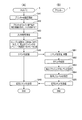
図5は、コマンドにより紙上フラッシングのレベルを設定する場合の動作を示すフローチャートであり、(A)はホストPC5の動作を示し、(B)はインクジェットプリンター1の動作を示す。
ホストPC5は、ホスト入力部112に接続された入力デバイスの操作により、プリンターの設定が開始されると(ステップSA1)、プリンタードライバー実行部102の機能により、設定画面を表示してユーザーの入力を受け付ける(ステップSA2)。このステップSA2では、例えば、紙上フラッシングのレベルを設定する画面が表示される。
FIGS. 5A and 5B are flowcharts showing the operation when the on-paper flushing level is set by a command. FIG. 5A shows the operation of the
When the setting of the printer is started by operating the input device connected to the host input unit 112 (step SA1), the
図6は、プリンタードライバー実行部102の機能によりホスト表示部113に表示される設定画面200の例を示す図である。設定画面200は、ユーザーが紙上フラッシングのレベルを設定するためのユーザーインターフェースであり、設定画面200を表示させるプリンタードライバー実行部102は入力受付部に相当する。
ここで、図6に示すユーザーインターフェースには、紙上フラッシングのレベルに関する記載はなく、「スループット優先モード」という動作モードをONにするかOFFにするかの入力が可能になっている。インクジェットプリンター1では、印刷時の動作モードとして、通常動作モードと、スループット優先モードという2種類の動作モードを排他的に選択可能であり、これら2つの動作モードを、設定画面200の入力により選択できる。スループット優先モードがOFFの場合は通常動作モードが選択される。
FIG. 6 is a diagram illustrating an example of a
Here, in the user interface shown in FIG. 6, there is no description regarding the level of flushing on paper, and it is possible to input whether the operation mode “throughput priority mode” is to be turned on or off. In the
通常動作モードは、紙上フラッシングを「レベル2」で行う動作モードである。レベル2はインク吐出量が少ないため、印刷後の搬送ロール紙R2で、紙上フラッシングによるインクが目立たない。従って、印刷品質の変化が小さいため、通常動作モードとしてユーザーに受け入れられる。一方、スループット優先モードは、スループットを高めた動作モードである。このスループット優先モードは、紙上フラッシングを「レベル1」で行う動作モードである。紙上フラッシングのインク吐出量を多くすることで、フラッシング間隔が長く、定期フラッシングの頻度が低くなるため、スループットが向上する。紙上フラッシングで吐出されるインクが多いため、印刷後の搬送ロール紙R2で印刷画像以外のインクの付着が視認され、印刷品質の低下と認識される可能性があるが、印刷品質よりもスループットを優先した動作モードとして受け入れられる。
The normal operation mode is an operation mode in which flushing on paper is performed at “
紙上フラッシングにおけるインク量が印刷品質や印刷動作にどのような影響を与えるか、専門家でないユーザーが理解することは、必ずしも容易とはいえない。従って、仮に設定画面200において紙上フラッシングのレベル設定と表示して、レベルを指定する入力操作をユーザーに求めた場合、ユーザーがインクジェットプリンター1を使いこなすことは容易とは言えない。これに対し、図6に示すように、ユーザーインターフェースである設定画面200では、スループット優先モードを選択するか、通常動作モードを選択するかの入力を行うことにより、紙上フラッシングのインク吐出量の多寡を設定できる構成となっている。
It is not always easy for a non-expert user to understand how the amount of ink in flushing on paper affects print quality and printing operation. Accordingly, if it is displayed on the
設定画面200には、スループット優先モードの選択/解除を指定するチェックボックス201と、チェックボックス201における指定を確定するボタン202と、設定を中止するボタン203とが配置される。チェックボックス201にチェックが付けられ、ボタン202が操作されると、スループット優先モードがONに設定される。また、チェックボックス201のチェックが外されてボタン202が操作されると、スループット優先モードがOFFに、すなわち、通常動作モードがONに設定される。
プリンタードライバー実行部102は、設定画面200においてボタン202が操作されると、チェックボックス201の指定に従って、紙上フラッシングのレベル設定コマンドを生成する。このコマンドは、例えば上述したコントロールコマンドとして生成できる。
On the
When the
図5に戻り、ユーザーインターフェースにおける入力内容が、例えばボタン202の操作によって確定されると(ステップSA3)、プリンタードライバー実行部102は、スループット優先モードのON/OFFに対応するコマンドを生成する(ステップSA4)。プリントモニター部103は、プリンタードライバー実行部102が出力するコマンドをインクジェットプリンター1に送信する(ステップSA5)。
Returning to FIG. 5, when the input content in the user interface is confirmed by, for example, operating the button 202 (step SA3), the printer
コマンド受信部50aは、ホストPC5が送信したコマンドを受信し、受信バッファー50gに記憶させる(ステップSB1)。その後、コマンド解析部50bは受信バッファー50gのコマンドを解析し(ステップSB2)、紙上フラッシングのレベル設定コマンドであると判定すると、コマンドとパラメーターとを設定部50cに渡す。設定部50cは、コマンドに付加されたパラメーターに基づき、コマンドで指定されたレベルを取得する(ステップSB3)。そして、設定部50cは、取得したレベルをもとにフラッシング設定データ52aを更新し、設定を行う(ステップSB4)。
The
設定の後、プリンター制御部50は、コマンドで指示された処理が完了したことを示す応答コマンドをホストPC5に送信する(ステップSB5)。プリントモニター部103は、インクジェットプリンター1から送信された応答コマンドを受信する(ステップSA6)。この応答コマンドはプリンタードライバー実行部102が生成したレベル設定コマンドへの応答である。プリントモニター部103は、プリンタードライバー実行部102のコマンドに対する応答であることを識別して、プリンタードライバー実行部102に設定が完了したことを通知してもよい。また、プリンター制御部50が生成する応答の形式は限定されず、上述したコマンド形式の応答コマンドの他、ステータスの通知の形式であってもよいし、他の形式のデータであってもよい。
After the setting, the
図5の動作により、設定部50cは、フラッシング設定データ52aを更新して、紙上フラッシングのレベルをレベル1またはレベル2に設定する。また、フラッシング設定データ52aでは、定期フラッシングまでの時間が設定される。紙上フラッシングがレベル1で行われると、ノズル内のインクが高頻度で入れ替えられる。このため、定期フラッシングの頻度を低下させても、増粘を防止できる。一方、紙上フラッシングがレベル2で行われると、定期フラッシングを通常の頻度で行う必要がある。フラッシング設定データ52aでは、紙上フラッシングのレベルに対応付けて、定期フラッシングのフラッシング間隔が設定されている。このため、紙上フラッシングのレベルが設定されると、これに対応するフラッシング間隔が参照される構成となっている。
ここで、プリンタードライバー実行部102が、紙上フラッシングのレベルを設定するコマンドとともに、フラッシング間隔を設定するコマンドを生成してもよい。すなわち、プリンタードライバー実行部102は、設定画面200によりスループット優先モードがONにされた場合に、紙上フラッシングのレベルをレベル1に指定するコマンドと、フラッシング間隔を標準より短い時間に設定するコマンドを生成してもよい。また、プリンタードライバー実行部102は、設定画面200によりスループット優先モードがOFFにされた場合に、紙上フラッシングのレベルをレベル2に指定するコマンドと、フラッシング間隔を標準の時間に設定するコマンドを生成してもよい。この場合、フラッシング設定データ52aにおいて紙上フラッシングのレベルとフラッシング間隔とを対応付ける必要がなく、ホストPC5の制御によってフラッシング間隔を変更できる。
By the operation of FIG. 5, the setting unit 50c updates the
Here, the printer
また、設定画面200を利用して設定されるスループット優先モードの設定状態は、ホストPC5においてはホスト表示部113に設定状態を表示させて確認できる。また、プリンター1では、スイッチパネルに設けられる表示部に、現在のスループット優先モードの設定状態を表示してもよい。この表示は、操作スイッチ54の操作に応じて表示されてもよい。或いは、設定部50cが紙上フラッシングのレベル設定コマンドに従って、コマンドで指定されたレベルを設定した場合に、設定したレベルに対応するスループット優先モードを表示部に表示してもよい。
Further, the setting state of the throughput priority mode set using the
図7は、印刷に係る印刷システム2の動作を示すフローチャートであり、(A)はホストPC5の動作を示し、(B)はインクジェットプリンター1の動作を示す。
ホストPC5のアプリケーション実行部101は、印刷対象のデータと印刷指示を生成し、プリンタードライバー実行部102に出力する(ステップSA11)。アプリケーション実行部101が生成するデータは、文字列の文字コードやバーコードのコード、或いは、画像データを含んでいてもよい。
プリンタードライバー実行部102は、アプリケーション実行部101から入力されたデータと印刷指示を取得し(ステップSA12)、印刷指示コマンドまたはコマンド群を生成する(ステップSA13)。プリンタードライバー実行部102は、ステップSA14またはSA15で生成したコマンドまたはコマンド群をプリントモニター部103に出力し、プリントモニター部103がインクジェットプリンター1に送信する(ステップSA14)。
FIG. 7 is a flowchart showing the operation of the
The
The printer
コマンド受信部50aはホストPC5が送信したコマンドを受信し、受信バッファー50gに記憶させる(ステップSB11)。ホストPC5が送信したコマンドが複数のフォーマットコマンドを含むコマンド群を構成する場合、コマンド受信部50aは、コマンド群に含まれる複数のコマンドを順に受信バッファー50gに記憶させる。コマンド解析部50bは、受信バッファー50gのコマンドを順に解析し(ステップSB12)、印刷指示コマンドと印刷対象のデータを印刷制御部50eに渡す。印刷制御部50eは、印刷指示コマンドと印刷対象のデータを取得し(ステップSB13)、画像処理部50fを呼び出す。画像処理部50fは、印刷対象のデータをレンダリングしてプリントバッファー50hに印刷する画像データを展開する(ステップSB14)。
The
印刷制御部50eは、画像処理部50fがプリントバッファー50hに展開した画像データの各画素の色データ(例えば、RGB多値データ)を、プリンター記憶部52に記憶されたLUTによりC,M,Y,Kのインク量データに変換する。この色変換処理に続き胃、印刷制御部50eは、画素のインク量データを、インクジェットヘッド10の各色のノズルによって形成可能なドットデータに変換する2値化処理を行う(ステップSB15)。インクジェットヘッド10のノズルは、例えば、空白、小ドット、中ドット、大ドットの4種類のドット(詳細には空白と3種類のドット)を形成可能である。この場合、ノズルのドットデータは空白を含む4階調のデータに変換される。
The
ここで、フラッシング制御部50dは、フラッシング設定データ52aを参照し、紙上フラッシングのレベルを判定する(ステップSB16)。レベル1に設定されている場合、フラッシング制御部50dは、基準フラッシングパターン52bを用いて印刷フラッシングパターンを生成する(ステップSB17)。
基準フラッシングパターン52bは、インクジェットヘッド10のノズルからインクを吐出するノズルを選択するためのパターンであり、例えば、n列×m行(n,mは整数)のドットマトリクスパターンで構成される。このドットマトリクスパターンは空白ドット、およびフラッシングドットによって構成される。フラッシングドットはインクを吐出するノズルを示し、空白ドットはインクを吐出しないノズルを示す。フラッシング制御部50dは、ブラックヘッド24a、シアンヘッド25a、マゼンダヘッド26a、イエローヘッド27aのノズルについて、色毎に、n列×m行の基準フラッシングパターン52bを適用する。例えば、いずれかの色のヘッドがp列×q行(p、qは整数)のノズル列で構成される場合、n列×m行の基準フラッシングパターン52bをp列×q行に拡張する。これは、例えば、基準フラッシングパターン52bを縦方向にp/n倍し、横方向にq/m倍する演算を行い、端数を切り捨てることで実行できる。また、基準フラッシングパターン52bを複数並べて、p列×q行のパターンを切り出す方法でも実行できる。これらの処理により基準フラッシングパターン52bをノズルの配列に合わせて展開した後、フラッシング制御部50dは、フラッシングドットに重なるノズルを、インクを吐出するノズルとして選択する。以上の処理によって、ヘッドに配置された多数のノズルの中から、紙上フラッシングでインクを吐出するノズルが選択される。フラッシング制御部50dは、ブラックヘッド24a、シアンヘッド25a、マゼンダヘッド26a、イエローヘッド27aの全ノズルについて、各々のノズルのインクの吐出の有無を示す印刷フラッシングパターンを生成する。
Here, the
The
印刷フラッシングパターンが設定するインクの吐出量は、例えば一定とすることができる。上記の例のようにインクジェットヘッド10のノズルが4階調のインク吐出量を設定可能な場合、印刷フラッシングパターンは、空白ドットと、大中小いずれかのドットとを含むデータとなる。紙上フラッシングのインク量は、ノズル内のインクを入れ替えることが可能な最小限の量とすることが好ましく、この観点で大中小いずれかのドットが選択される。
The ink discharge amount set by the print flushing pattern can be, for example, constant. When the nozzles of the
一方、紙上フラッシングがレベル2に設定されている場合、フラッシング制御部50dは、基準フラッシングパターン52bをもとに、調整フラッシングパターンを生成する(ステップSB18)。調整フラッシングパターンは、基準フラッシングパターン52bに比べて、フラッシングドットの数が少ない。具体的には、フラッシング制御部50dは、基準フラッシングパターン52bのフラッシングドットの間に所定数の空白ドットを挿入するなど、フラッシングドットに対する空白ドットの割合を増やす処理を行い、調整フラッシングパターンを生成する。調整フラッシングパターンは、基準フラッシングパターン52bと同様のドットマトリクスパターンであるが、基準フラッシングパターン52bと列及び/または行の数が一致していても異なっていてもよい。その後、フラッシング制御部50dは、生成した調整フラッシングパターンを用いて印刷フラッシングパターンを生成する(ステップSB17)。すなわち、フラッシング制御部50dは、調整フラッシングパターンをインクジェットヘッド10のノズルの配列に合わせて展開し、フラッシングドットに重なるノズルを、インクを吐出するノズルとして選択する。調整フラッシングパターンの展開の方法は、基準フラッシングパターン52bを展開する場合と同様である。フラッシング制御部50dは、ブラックヘッド24a、シアンヘッド25a、マゼンダヘッド26a、イエローヘッド27aの全ノズルについて、各々のノズルのインクの吐出の有無を示す印刷フラッシングパターンを生成する。
On the other hand, when the on-paper flushing is set to
印刷制御部50eは、ステップSB17で生成された印刷フラッシングパターンを、ステップSB15の2値化処理で生成されたドットデータに重畳することにより、印刷データを生成する(ステップSB19)。この印刷データは、インクジェットヘッド10のノズル毎にインクの吐出量(例えば、空白を含む4階調)のデータであり、印刷対象の画像等を印刷するためのドットと、紙上フラッシングのドットとの両方を含む。印刷制御部50eは、各ノズルについて印刷フラッシングパターンとドットデータの論理和(OR)を求めて印刷データとする。従って、印刷データは、印刷フラッシングパターン及び紙上フラッシングよりも、多くのドットでインクを吐出させるデータとなる。
The
いずれかのノズルについて、ドットデータの大ドット、中ドットまたは小ドットと、印刷フラッシングパターンのドットとが重なった場合、印刷制御部50eは、インク吐出量の多い方のデータに従って当該ノズルのインク吐出量を決めて印刷データを生成する。これにより、紙上フラッシングの実行により印刷対象の画像の印刷品質が変化するのを防止できる。
また、ステップSB19で、印刷制御部50eは、搬送ロール紙R2の印刷対象領域から外れた位置では、印刷フラッシングパターンのドットは無視し、ノズルのインク吐出量をゼロにする。すなわち、搬送ロール紙R2において画像を印刷する範囲として指定された印刷対象領域でのみ、紙上フラッシングのインクを吐出する。これにより、搬送ロール紙R2において余白となる部分には紙上フラッシングのインクが付着しないので、紙上フラッシングの印刷品質への影響を抑えることができる。また、搬送ロール紙R2がラベル用紙である場合は印刷面に剥離紙が露出することがある。このように印刷面にインクを吸着しない部分がある場合、印刷対象領域外にインクを付着させると印刷後の汚損の要因になる可能性がある。本実施形態では印刷対象領域外にインクを吐出しないので、このような汚損を防止できる。
When a large dot, medium dot or small dot of dot data overlaps with a dot of the print flushing pattern for any of the nozzles, the
In step SB19, the
印刷制御部50eは、印刷データに従ってインクジェットヘッド10及び搬送モーター31を駆動して、印刷する(ステップSB20)。
印刷完了後、プリンター制御部50は印刷が完了したことを示す応答コマンドをホストPC5に送信する(ステップSB21)。プリントモニター部103は、インクジェットプリンター1から送信された応答コマンドを受信する(ステップSA15)。この応答コマンドはプリンタードライバー実行部102が生成した印刷指示コマンドへの応答である。プリントモニター部103は、プリンタードライバー実行部102に印刷が完了したことを通知してもよい。
The
After the printing is completed, the
また、図7の動作の実行中、フラッシング制御部50dは、フラッシング設定データ52aにより定められるフラッシング間隔に従って、定期フラッシングを実行する。この定期フラッシングの実行間隔は紙上フラッシングのレベルに対応して決定され、スループット優先モードでは、通常動作モードより長い時間に設定される。このため、定期フラッシングの頻度を減らしてスループットの向上を図ることができる。
Further, during execution of the operation of FIG. 7, the
以上説明したように、本実施形態に係る印刷システム2は、インクジェットプリンター1及びホストPC5を備える。インクジェットプリンター1は、ノズルを備えるインクジェットヘッド10と、搬送ロール紙R2を搬送する搬送部32とを備える。プリンター制御部50は、インクジェットヘッド10のインクノズルからメンテナンスユニット90にインクを吐出する定期フラッシングを実行させる。また、プリンター制御部50は、インクジェットヘッド10のインクノズルから搬送ロール紙R2上にインクを吐出する紙上フラッシング動作を実行させる。ホストPC5は、プリンタードライバー実行部102により、通常動作モードとスループット優先モードを指示するユーザーインターフェースを提供する。ユーザーインターフェースを用いてスループット優先モードが指定された場合に、プリンタードライバー実行部102は、インクジェットプリンター1のフラッシング動作の実行条件を指定するコマンドを生成する。このコマンドは、プリントモニター部103が送信する。プリンター制御部50は、ホストPC5が送信するコマンドを受信して解析し、受信したコマンドに従って紙上フラッシング動作の実行に係る条件を設定する。これにより、ユーザーが印刷スループットを優先するかどうかを判断して入力を行うと、この入力に応じて、搬送ロール紙R2の搬送経路HKでフラッシングを行う場合の実行条件が設定される。従って、ユーザーが、フラッシングの影響とフラッシング動作の実行条件に関する知識を有しているか否かにかかわらず、容易に、適切な設定ができる。
As described above, the
また、プリンター制御部50は、インク吐出量が異なる複数のレベルで紙上フラッシング動作を実行可能である。プリンタードライバー実行部102は、ユーザーインターフェースを用いてスループット優先モードが指定された場合、紙上フラッシング動作の実行条件を指定するコマンドを生成する。これにより、搬送ロール紙R2の搬送経路HKでフラッシングを行う場合のインク吐出量を多くするか否かの条件を、容易に、適切に設定できる。
また、プリンタードライバー実行部102は、ユーザーインターフェースを用いて通常動作モードが指示された場合、デフォルトの値であるレベル2を指定するレベル設定コマンドを生成する。これにより、搬送ロール紙R2の搬送経路HKでフラッシングを行う場合のインク吐出量を多くするか否かの条件を、容易に、適切に設定できる。
In addition, the
In addition, when the normal operation mode is instructed using the user interface, the printer
また、プリンター制御部50は、紙上フラッシング動作の実行後、予め設定された時間であるフラッシング間隔に従って定期フラッシング動作を実行し、レベル1に対応するフラッシング時間は、レベル2に対応するフラッシング間隔よりも長い。このため、スループットを向上させることができる。
In addition, after executing the on-paper flushing operation, the
また、定期フラッシング動作(通常フラッシング動作)は、インクジェットヘッド10をメンテナンスユニット90の位置まで移動してインクノズルからインクを吐出するフラッシング動作である。また、紙上フラッシング動作(媒体上フラッシング動作)は、インクジェットヘッド10のインクノズルから搬送ロール紙R2の搬送経路に位置したままインクを搬送ロール紙R2上に吐出するフラッシング動作である。この構成において、ユーザーは、通常動作モードとスループット優先モードを指示することで、紙上フラッシング動作の実行条件を、容易に、適切に設定できる。
The regular flushing operation (normal flushing operation) is a flushing operation in which the
なお、上述した実施の形態は、あくまでも本発明の一態様を示すものであり、本発明の範囲内で任意に変形および応用が可能である。
例えば、上述した実施形態では、紙上フラッシングにおけるインク吐出量をレベル別に異なる量にするため、基準フラッシングパターン52bと、基準フラッシングパターン52bから生成する調整フラッシングパターンとを使い分ける例を挙げて説明した。すなわち、紙上フラッシングのレベル1では、基準フラッシングパターン52bを使用し、レベル2では調整フラッシングパターンを生成する例を説明した。本発明はこれに限定されるものではなく、例えば、調整フラッシングパターンを、予め、プリンター記憶部52に記憶していてもよい。この場合、調整フラッシングパターンを生成する処理が不要となり負荷を軽減できる。また、紙上フラッシングのインク吐出量を複数階調とすることも可能である。この場合、基準フラッシングパターン52b及び調整フラッシングパターンのフラッシングドットが、インク吐出量の階調データを有する構成とすればよい。また、調整フラッシングパターンを、基準フラッシングパターン52bとフラッシングドットが同じ位置にあり、インク吐出量が異なるデータとして生成できる。この場合、調整フラッシングパターンの生成および展開の処理が容易になるという利点がある。また、紙上フラッシングのレベルが3段階以上ある場合に、複数の調整フラッシングパターンを生成してもよいし、各レベルに対応する調整フラッシングパターンをプリンター記憶部52に記憶してもよいことは上記の通りである。
また、インクジェットプリンター1の印刷時の動作モードはスループット優先モードと通常動作モードに限定されず、設定画面200において、より多くの動作モードから1つの動作モードを指定できる構成としてもよい。また、設定画面200は、スループット優先モードのON/OFFだけでなく他の設定項目について設定可能なユーザーインターフェースであってもよい。この場合、プリンタードライバー実行部102は、設定画面200により設定された複数の項目に関するコマンドを、コマンド群として生成してもよい。
The above-described embodiment is merely an aspect of the present invention, and can be arbitrarily modified and applied within the scope of the present invention.
For example, in the above-described embodiment, an example has been described in which the
Further, the operation mode at the time of printing of the
また、図4に示す各機能ブロックはハードウェアとソフトウェアの協働により任意に実現可能であり、特定のハードウェア構成を示唆するものではない。また、ホストPC5、インクジェットプリンター1の各機能を、これら装置に外部接続される別の装置に持たせるようにしてもよい。また、ホストPC5、インクジェットプリンター1は、外部接続される記憶媒体に記憶させたプログラムを実行することにより、各種動作を実行してもよい。また、インクジェットプリンター1と同様の印刷ユニットを内蔵した複合機等にも本発明を適用可能である。
Each functional block shown in FIG. 4 can be arbitrarily realized by cooperation of hardware and software, and does not suggest a specific hardware configuration. Further, the functions of the
1…インクジェットプリンター(印刷装置)、2…印刷システム、5…ホストPC(印刷制御装置)、10…インクジェットヘッド(印刷ヘッド)、12…ロール紙収納部、19…用紙検出器、20…ブラックマーク検出器、21…印刷部、22…プラテン、24…ブラックヘッドユニット、24a…ブラックヘッド、24b…ブラックノズル列、25…シアンヘッドユニット、25a…シアンヘッド、25b…シアンノズル列、26…マゼンダヘッドユニット、26a…マゼンダヘッド、26b…マゼンダノズル列、27…イエローヘッドユニット、27a…イエローヘッド、32…搬送部、44…制御基板、50…プリンター制御部(制御部)、50a…コマンド受信部、50b…コマンド解析部、50c…設定部、50d…フラッシング制御部、50e…印刷制御部、50f…画像処理部、50g…受信バッファー、50h…プリントバッファー、52…プリンター記憶部、52a…フラッシング設定データ、52b…基準フラッシングパターン、90…メンテナンスユニット(インク受け部)、100…ホスト制御部、101…アプリケーション実行部、102…プリンタードライバー実行部(入力受付部、コマンド制御部)、103…プリントモニター部(コマンド送信部)、111…ホスト記憶部、112…ホスト入力部、113…ホスト表示部、200…設定画面、201…チェックボックス、202、203…ボタン、BM…ブラックマーク、F…搬送方向、HK…搬送経路、HP…ホームポジション、PP…印刷ポジション、R…ロール紙(印刷媒体)。
DESCRIPTION OF
Claims (5)
印刷媒体を搬送する搬送部と、
前記印刷ヘッドのインクノズルからインクをインク受け部に吐出する第1フラッシング、及び、前記印刷ヘッドのインクノズルから前記印刷媒体上にインクを吐出する第2フラッシングと、を実行させる制御部と、を備える印刷装置と、
第1動作モード、または、前記第1動作モードよりも印刷スループットを優先する第2動作モードを指示する入力を受け付ける入力受付部と、
前記入力受付部が受け付けた前記入力により動作モードが指示された場合に、前記印刷装置のフラッシングの実行条件を指定するコマンドを生成するコマンド制御部と、
前記コマンド制御部が生成したコマンドを送信するコマンド送信部と、を備える印刷制御装置と、を有し、
前記印刷装置が備える前記制御部は、前記印刷制御装置が送信する前記コマンドを受信して解析し、受信した前記コマンドに従って前記第1フラッシングを実行するフラッシング時間を設定し、設定されたフラッシング時間ごとに前記第1フラッシングを実行させることが可能であり、
前記印刷制御装置の前記コマンド制御部は、前記動作モードとして前記第2動作モードが指示された場合に、第1実行条件を指定するコマンドを生成し、前記第1動作モードが指示された場合に、第2実行条件を指定するコマンドを生成し、
前記第1実行条件を指定するコマンドに従って設定される前記第1フラッシングの前記フラッシング時間は、前記第2実行条件を指定するコマンドに従って設定される前記第1フラッシングの前記フラッシング時間より長い、印刷システム。 A print head comprising ink nozzles;
A transport unit for transporting the print medium;
A control unit that executes a first flushing that ejects ink from the ink nozzles of the print head to an ink receiving unit and a second flushing that ejects ink from the ink nozzles of the print head onto the print medium; A printing apparatus comprising:
An input receiving unit that receives an input for instructing a first operation mode or a second operation mode that prioritizes print throughput over the first operation mode;
A command control unit that generates a command that specifies an execution condition of flushing of the printing apparatus when an operation mode is instructed by the input received by the input receiving unit;
A command control unit that transmits a command generated by the command control unit, and a print control device comprising:
The control unit included in the printing apparatus receives and analyzes the command transmitted by the printing control apparatus , sets a flushing time for executing the first flushing in accordance with the received command , and sets each flushing time. Can perform the first flushing ;
The command control unit of the print control device generates a command specifying a first execution condition when the second operation mode is instructed as the operation mode, and when the first operation mode is instructed. , Generate a command to specify the second execution condition,
The printing system , wherein the flushing time of the first flushing set according to the command specifying the first execution condition is longer than the flushing time of the first flushing set according to the command specifying the second execution condition .
前記第1実行条件を指定するコマンドに従って設定される前記第2フラッシングの前記インク吐出量は、前記第2実行条件を指定するコマンドに従って設定される前記第2フラッシングの前記インク吐出量より多い、請求項1に記載の印刷システム。 The control unit of the printing apparatus can set the ink discharge amount of the second flushing as a condition related to the execution of the flushing, and can execute the second flushing with a plurality of different set ink discharge amounts. It is in,
The ink discharge amount of the second flushing is set in accordance with a command that specifies the previous SL first execution condition is larger than the ink discharge amount of the second flushing is set in accordance with a command designating said second execution condition, The printing system according to claim 1.
前記第2フラッシングは、前記印刷媒体の搬送経路に位置する前記印刷ヘッドのインクノズルからインクを前記印刷媒体上に吐出するフラッシングである、請求項1または2に記載の印刷システム。 The first flushing is a flushing that moves the print head to a position of the ink receiving portion and discharges ink from an ink nozzle of the print head to the ink receiving portion,
The second flushing, the ink from the ink nozzles of the print head is flushing for ejecting onto the print medium, the printing system according to claim 1 or 2 located in the transport path of the print medium.
第1動作モード、または、前記1動作モードよりも印刷動作のスループットを優先する第2動作モードを指示する入力を受け付ける入力受付部と、
前記入力受付部が受け付けた前記入力により動作モードが指示された場合に、前記印刷装置の前記制御部に、前記フラッシングの実行条件として前記フラッシング時間を設定させるコマンドを生成するコマンド制御部と、
前記コマンド制御部が生成したコマンドを送信するコマンド送信部と、
を備え、
前記印刷制御装置の前記コマンド制御部は、前記動作モードとして前記第2動作モードが指示された場合に第1実行条件を指定するコマンドを生成し、前記第1動作モードが指示された場合に第2実行条件を指定するコマンドを生成し、
前記第1実行条件として設定される前記フラッシング時間が、前記第2実行条件として設定される前記フラッシング時間より長いことを特徴とする印刷制御装置。 First flushing for ejecting ink from the print head and ink nozzles of the print head to the ink receiving portion is executed at each set flushing time, and ink is ejected from the ink nozzles of the print head onto the print medium A printing control device for instructing the printing device to execute flushing and printing to a printing device including a control unit that executes the second flushing .
An input receiving unit that receives an input for instructing a first operation mode or a second operation mode that prioritizes throughput of the printing operation over the first operation mode;
When the input receiving unit is an operation mode by the input is the instruction received, the control unit of the printing apparatus, and a command control unit which generates a command as an execution condition of the flushing Ru is set to the flushing time,
A command transmission unit for transmitting a command generated by the command control unit;
Equipped with a,
The command control unit of the print control device generates a command for designating a first execution condition when the second operation mode is instructed as the operation mode, and when the first operation mode is instructed, 2 Generate a command to specify the execution condition,
The printing control apparatus , wherein the flushing time set as the first execution condition is longer than the flushing time set as the second execution condition .
第1動作モード、または、前記第1動作モードよりも印刷動作のスループットを優先する第2動作モードを指示する入力を受け付け、
受け付けた前記入力により動作モードが指示された場合に、前記フラッシングの実行条件として前記フラッシング時間を設定させるコマンドを生成し、
受け付けた前記入力により前記第2動作モードが指示された場合に前記フラッシングの実行条件として第1実行条件を指定するコマンドを生成し、
受け付けた前記入力により前記第1動作モードが指示された場合に第2実行条件を指定するコマンドを生成し、
生成したコマンドを送信し、
前記第1実行条件として設定される前記フラッシング時間が、前記第2実行条件として設定される前記フラッシング時間より長い、印刷制御方法。 A command is sent, and a first flushing for ejecting ink from the ink nozzles of the print head to the ink receiving portion is executed at each set flushing time, and the ink is ejected from the ink nozzles of the print head onto the print medium. 2 Flushing and a print control method for instructing print execution,
Receiving an input for instructing the first operation mode or the second operation mode in which the throughput of the printing operation is prioritized over the first operation mode;
When the operation mode by the input reception is instructed, it generates a command as an execution condition of the flushing Ru is set to the flushing time,
When the second operation mode is instructed by the received input, a command for specifying the first execution condition as the execution condition for the flushing is generated,
Generating a command for designating a second execution condition when the first operation mode is instructed by the received input;
And sends the generated command,
The printing control method , wherein the flushing time set as the first execution condition is longer than the flushing time set as the second execution condition .
Priority Applications (3)
| Application Number | Priority Date | Filing Date | Title |
|---|---|---|---|
| JP2014057688A JP6318747B2 (en) | 2014-03-20 | 2014-03-20 | Printing system, printing control apparatus, and printing control method |
| US14/624,855 US9889668B2 (en) | 2014-03-20 | 2015-02-18 | Printing system, print control device, and print control method |
| CN201510105620.6A CN104924782B (en) | 2014-03-20 | 2015-03-11 | Print system, print control unit and print control program |
Applications Claiming Priority (1)
| Application Number | Priority Date | Filing Date | Title |
|---|---|---|---|
| JP2014057688A JP6318747B2 (en) | 2014-03-20 | 2014-03-20 | Printing system, printing control apparatus, and printing control method |
Related Child Applications (1)
| Application Number | Title | Priority Date | Filing Date |
|---|---|---|---|
| JP2018059459A Division JP6489258B2 (en) | 2018-03-27 | 2018-03-27 | Printing system, printing control apparatus, and printing control method |
Publications (3)
| Publication Number | Publication Date |
|---|---|
| JP2015182224A JP2015182224A (en) | 2015-10-22 |
| JP2015182224A5 JP2015182224A5 (en) | 2017-03-30 |
| JP6318747B2 true JP6318747B2 (en) | 2018-05-09 |
Family
ID=54112331
Family Applications (1)
| Application Number | Title | Priority Date | Filing Date |
|---|---|---|---|
| JP2014057688A Active JP6318747B2 (en) | 2014-03-20 | 2014-03-20 | Printing system, printing control apparatus, and printing control method |
Country Status (3)
| Country | Link |
|---|---|
| US (1) | US9889668B2 (en) |
| JP (1) | JP6318747B2 (en) |
| CN (1) | CN104924782B (en) |
Cited By (2)
| Publication number | Priority date | Publication date | Assignee | Title |
|---|---|---|---|---|
| US20220379616A1 (en) * | 2021-05-31 | 2022-12-01 | Brother Kogyo Kabushiki Kaisha | Printer, control method, and non-transitory computer-readable medium storing computer-readable instructions |
| US12045521B1 (en) | 2023-02-21 | 2024-07-23 | Ricoh Company, Ltd. | Halftone modification mechanism |
Families Citing this family (17)
| Publication number | Priority date | Publication date | Assignee | Title |
|---|---|---|---|---|
| JP6318747B2 (en) * | 2014-03-20 | 2018-05-09 | セイコーエプソン株式会社 | Printing system, printing control apparatus, and printing control method |
| US10990757B2 (en) | 2016-05-13 | 2021-04-27 | Microsoft Technology Licensing, Llc | Contextual windows for application programs |
| EP3492262B1 (en) * | 2016-08-01 | 2021-04-21 | I. Mer Co., Ltd. | Printing machine having ductor roller, correction device, and printing machine correction method |
| US10800175B2 (en) * | 2016-09-01 | 2020-10-13 | Hewlett-Packard Development Company, L.P. | Gap spits at printheads |
| CN106626353A (en) * | 2016-10-24 | 2017-05-10 | 江苏文洪印刷机械有限公司 | Method for manufacturing die cutting indentation base plate |
| US11188710B2 (en) * | 2016-12-30 | 2021-11-30 | Dropbox, Inc. | Inline content item editor commands |
| US9929743B1 (en) * | 2017-03-13 | 2018-03-27 | Chicago Mercantile Exchange Inc. | Data compression of electronic data transaction request messages |
| JP6514261B2 (en) * | 2017-04-18 | 2019-05-15 | ローランドディー.ジー.株式会社 | Ink jet printer and printing method |
| JP6563436B2 (en) * | 2017-04-18 | 2019-08-21 | ローランドディー.ジー.株式会社 | Inkjet printer |
| US20180329592A1 (en) * | 2017-05-12 | 2018-11-15 | Microsoft Technology Licensing, Llc | Contextual windows for application programs |
| US10682857B2 (en) | 2018-06-26 | 2020-06-16 | Ricoh Company, Ltd. | Adaptive ink flushing of a printer |
| US11148454B2 (en) * | 2018-08-31 | 2021-10-19 | Canon Finetech Nisca Inc. | Sheet bundle discharging apparatus and bookbinding apparatus |
| CN113165399B (en) * | 2018-11-30 | 2023-08-29 | 耐克创新有限合伙公司 | System and method for printing on flexible material |
| US11072178B1 (en) | 2020-02-25 | 2021-07-27 | Ricoh Company, Ltd. | Adaptive flushing using bit planes |
| JP7484280B2 (en) * | 2020-03-23 | 2024-05-16 | ブラザー工業株式会社 | Liquid ejection device |
| JP2022070319A (en) * | 2020-10-27 | 2022-05-13 | セイコーエプソン株式会社 | Printer, tension adjustment method of conveyance belt in the printer, and adjustment pattern printing control program |
| US11999166B2 (en) | 2022-08-22 | 2024-06-04 | Ricoh Company, Ltd. | Adaptive ink flushing of overlap nozzles of a printer |
Family Cites Families (33)
| Publication number | Priority date | Publication date | Assignee | Title |
|---|---|---|---|---|
| JPH0844512A (en) * | 1994-07-29 | 1996-02-16 | Canon Inc | Printing device, electronic equipment connecting same and their control method |
| US5903288A (en) * | 1996-02-14 | 1999-05-11 | Seiko Epson Corporation | Apparatus and method for flushing ink-jet recording heads without suspension of printing |
| US6619783B2 (en) * | 1998-11-20 | 2003-09-16 | Seiko Epson Corp | Flushing position controller incorporated in ink-jet recording apparatus and flushing method used for the same |
| JP3161534B2 (en) * | 1998-11-27 | 2001-04-25 | セイコーエプソン株式会社 | Ink jet recording device |
| US6709088B2 (en) * | 2000-04-18 | 2004-03-23 | Seiko Epson Corporation | Inkjet recording apparatus |
| JP2003039693A (en) * | 2001-07-31 | 2003-02-13 | Canon Inc | Ink jet recorder and ink jet recording method |
| JP3800193B2 (en) * | 2003-03-27 | 2006-07-26 | ブラザー工業株式会社 | Image forming apparatus and recovery discharge method of print head |
| JP2004358791A (en) | 2003-06-04 | 2004-12-24 | Seiko Epson Corp | Inkjet printer, printing system, control method of inkjet printer, and program |
| JP2005161615A (en) * | 2003-12-01 | 2005-06-23 | Canon Inc | Inkjet recording method |
| JP2005343010A (en) * | 2004-06-02 | 2005-12-15 | Canon Inc | Inkjet recording device and inkjet recording method |
| JP2006001052A (en) * | 2004-06-15 | 2006-01-05 | Canon Inc | Sheet face preliminary discharging method and inkjet recorder |
| JP4869614B2 (en) * | 2005-03-28 | 2012-02-08 | 大日本スクリーン製造株式会社 | PRINT SYSTEM, CONTROLLER, PRINT JOB CREATION DEVICE, PRINT PROCESSING EXECUTION METHOD, AND PROGRAM |
| JP5014599B2 (en) * | 2005-06-23 | 2012-08-29 | 大日本スクリーン製造株式会社 | Printing system, printing apparatus controller, printing processing execution method, and program |
| JP2007076156A (en) * | 2005-09-14 | 2007-03-29 | Brother Ind Ltd | Printer |
| JP4730066B2 (en) | 2005-11-15 | 2011-07-20 | 富士ゼロックス株式会社 | Droplet discharge device |
| JP2009154297A (en) * | 2007-12-25 | 2009-07-16 | Seiko Epson Corp | Flushing method in fluid jet apparatus and fluid jet apparatus |
| US8262196B2 (en) * | 2007-12-27 | 2012-09-11 | Ricoh Production Print Solutions LLC | Methods and apparatus to provide user-customizable flush patterns in an ink-based printing system |
| JP2010105306A (en) * | 2008-10-31 | 2010-05-13 | Brother Ind Ltd | Ink ejection device and its control method |
| JP4720924B2 (en) * | 2009-03-24 | 2011-07-13 | ブラザー工業株式会社 | Recording device |
| JP5459492B2 (en) * | 2010-03-17 | 2014-04-02 | 株式会社リコー | Image forming apparatus |
| JP5772072B2 (en) * | 2011-03-07 | 2015-09-02 | セイコーエプソン株式会社 | Fluid ejection device, flushing method, and flushing program |
| CN202293660U (en) * | 2011-09-14 | 2012-07-04 | 深圳市华星光电技术有限公司 | Ink jetting unit and device |
| US8506046B2 (en) * | 2011-09-23 | 2013-08-13 | Infoprint Solutions Company Llc | Inkjet nozzle flushing mechanism |
| US9809036B2 (en) * | 2011-09-23 | 2017-11-07 | Ricoh Company, Ltd. | Dynamic inkjet nozzle flushing mechanism |
| JP6102210B2 (en) * | 2012-11-20 | 2017-03-29 | セイコーエプソン株式会社 | Printing device |
| JP6149179B2 (en) * | 2012-11-20 | 2017-06-21 | セイコーエプソン株式会社 | Liquid ejection device |
| JP6051819B2 (en) * | 2012-11-30 | 2016-12-27 | セイコーエプソン株式会社 | Printing apparatus and printing method |
| JP6119267B2 (en) * | 2013-01-24 | 2017-04-26 | セイコーエプソン株式会社 | Printing apparatus and printing method |
| US8944553B2 (en) * | 2013-02-22 | 2015-02-03 | Ricoh Company, Ltd. | Flush line generation in printing systems that utilize control marks |
| JP6079364B2 (en) * | 2013-03-27 | 2017-02-15 | ブラザー工業株式会社 | Liquid ejection device |
| CN103395292B (en) * | 2013-08-13 | 2015-12-09 | 鲁继烈 | Inkjet printer head protection cleaning method and shower nozzle protection cleaning fluid |
| JP6347116B2 (en) * | 2014-02-19 | 2018-06-27 | セイコーエプソン株式会社 | Printing apparatus and printing method |
| JP6318747B2 (en) * | 2014-03-20 | 2018-05-09 | セイコーエプソン株式会社 | Printing system, printing control apparatus, and printing control method |
-
2014
- 2014-03-20 JP JP2014057688A patent/JP6318747B2/en active Active
-
2015
- 2015-02-18 US US14/624,855 patent/US9889668B2/en active Active
- 2015-03-11 CN CN201510105620.6A patent/CN104924782B/en active Active
Cited By (2)
| Publication number | Priority date | Publication date | Assignee | Title |
|---|---|---|---|---|
| US20220379616A1 (en) * | 2021-05-31 | 2022-12-01 | Brother Kogyo Kabushiki Kaisha | Printer, control method, and non-transitory computer-readable medium storing computer-readable instructions |
| US12045521B1 (en) | 2023-02-21 | 2024-07-23 | Ricoh Company, Ltd. | Halftone modification mechanism |
Also Published As
| Publication number | Publication date |
|---|---|
| US9889668B2 (en) | 2018-02-13 |
| US20150266298A1 (en) | 2015-09-24 |
| JP2015182224A (en) | 2015-10-22 |
| CN104924782A (en) | 2015-09-23 |
| CN104924782B (en) | 2018-03-02 |
Similar Documents
| Publication | Publication Date | Title |
|---|---|---|
| JP6318747B2 (en) | Printing system, printing control apparatus, and printing control method | |
| JP2006192636A (en) | Liquid delivering system, liquid delivering apparatus, liquid delivering method, program and liquid delivering controlling apparatus | |
| CN107264101B (en) | Printing method and printing apparatus | |
| JP5256963B2 (en) | Printing apparatus and printing method | |
| JP6489258B2 (en) | Printing system, printing control apparatus, and printing control method | |
| JP2010012660A (en) | Recorder | |
| US7159960B2 (en) | Liquid ejecting method, liquid ejecting apparatus, and liquid ejecting system for forming dots up to edge of a medium | |
| US8582167B2 (en) | Print control apparatus, program, and print control method with reduced recording agent consumption | |
| JP2019136999A (en) | Liquid discharging device, and printing method | |
| JP2015147340A (en) | Printer and control method of the same | |
| JP2012061758A (en) | Image forming system, program, and storage medium storing the program | |
| JP2006334984A (en) | Printing controller, printing method, and program | |
| JP2011061328A (en) | Image processing method, image processor, image forming device, program, storage medium, and image forming system | |
| US20120105530A1 (en) | Control apparatus for a liquid ejecting head, liquid ejecting apparatus, and control method for a liquid ejecting head | |
| US9019517B2 (en) | Image reading apparatus, image forming system, and method for performing image and transport calibration | |
| US10071580B2 (en) | Printing method and printing apparatus | |
| JP5969236B2 (en) | Ink discharge amount control device | |
| JP2019185590A (en) | Bar code generation device and bar code generation method | |
| US20090010663A1 (en) | Printing apparatus and printing method | |
| JP2005335139A (en) | Printer and printing method | |
| JP2004338303A (en) | Printing device, printing method, and printing system | |
| JP2006007640A (en) | Printer, method of printing, and printing system | |
| JP2005001189A (en) | Printer and printing method | |
| JP2024088192A (en) | Printing system and screen display method | |
| JP2005153395A (en) | Printer, method of printing, and printing system |
Legal Events
| Date | Code | Title | Description |
|---|---|---|---|
| RD04 | Notification of resignation of power of attorney |
Free format text: JAPANESE INTERMEDIATE CODE: A7424 Effective date: 20160617 |
|
| RD03 | Notification of appointment of power of attorney |
Free format text: JAPANESE INTERMEDIATE CODE: A7423 Effective date: 20160628 |
|
| A521 | Request for written amendment filed |
Free format text: JAPANESE INTERMEDIATE CODE: A523 Effective date: 20170221 |
|
| A621 | Written request for application examination |
Free format text: JAPANESE INTERMEDIATE CODE: A621 Effective date: 20170221 |
|
| A131 | Notification of reasons for refusal |
Free format text: JAPANESE INTERMEDIATE CODE: A131 Effective date: 20171024 |
|
| A977 | Report on retrieval |
Free format text: JAPANESE INTERMEDIATE CODE: A971007 Effective date: 20171025 |
|
| A521 | Request for written amendment filed |
Free format text: JAPANESE INTERMEDIATE CODE: A523 Effective date: 20171215 |
|
| TRDD | Decision of grant or rejection written | ||
| A01 | Written decision to grant a patent or to grant a registration (utility model) |
Free format text: JAPANESE INTERMEDIATE CODE: A01 Effective date: 20180306 |
|
| A61 | First payment of annual fees (during grant procedure) |
Free format text: JAPANESE INTERMEDIATE CODE: A61 Effective date: 20180319 |
|
| R150 | Certificate of patent or registration of utility model |
Ref document number: 6318747 Country of ref document: JP Free format text: JAPANESE INTERMEDIATE CODE: R150 |