JP6318316B2 - Coating apparatus and coating method for coating liquid on curved substrate - Google Patents
Coating apparatus and coating method for coating liquid on curved substrate Download PDFInfo
- Publication number
- JP6318316B2 JP6318316B2 JP2018505041A JP2018505041A JP6318316B2 JP 6318316 B2 JP6318316 B2 JP 6318316B2 JP 2018505041 A JP2018505041 A JP 2018505041A JP 2018505041 A JP2018505041 A JP 2018505041A JP 6318316 B2 JP6318316 B2 JP 6318316B2
- Authority
- JP
- Japan
- Prior art keywords
- slit nozzle
- coating liquid
- coating
- slit
- curved
- Prior art date
- Legal status (The legal status is an assumption and is not a legal conclusion. Google has not performed a legal analysis and makes no representation as to the accuracy of the status listed.)
- Active
Links
Images


Classifications
-
- B—PERFORMING OPERATIONS; TRANSPORTING
- B05—SPRAYING OR ATOMISING IN GENERAL; APPLYING FLUENT MATERIALS TO SURFACES, IN GENERAL
- B05C—APPARATUS FOR APPLYING FLUENT MATERIALS TO SURFACES, IN GENERAL
- B05C5/00—Apparatus in which liquid or other fluent material is projected, poured or allowed to flow on to the surface of the work
- B05C5/02—Apparatus in which liquid or other fluent material is projected, poured or allowed to flow on to the surface of the work the liquid or other fluent material being discharged through an outlet orifice by pressure, e.g. from an outlet device in contact or almost in contact, with the work
- B05C5/0254—Coating heads with slot-shaped outlet
- B05C5/0258—Coating heads with slot-shaped outlet flow controlled, e.g. by a valve
-
- B—PERFORMING OPERATIONS; TRANSPORTING
- B05—SPRAYING OR ATOMISING IN GENERAL; APPLYING FLUENT MATERIALS TO SURFACES, IN GENERAL
- B05C—APPARATUS FOR APPLYING FLUENT MATERIALS TO SURFACES, IN GENERAL
- B05C5/00—Apparatus in which liquid or other fluent material is projected, poured or allowed to flow on to the surface of the work
- B05C5/02—Apparatus in which liquid or other fluent material is projected, poured or allowed to flow on to the surface of the work the liquid or other fluent material being discharged through an outlet orifice by pressure, e.g. from an outlet device in contact or almost in contact, with the work
-
- B—PERFORMING OPERATIONS; TRANSPORTING
- B05—SPRAYING OR ATOMISING IN GENERAL; APPLYING FLUENT MATERIALS TO SURFACES, IN GENERAL
- B05C—APPARATUS FOR APPLYING FLUENT MATERIALS TO SURFACES, IN GENERAL
- B05C11/00—Component parts, details or accessories not specifically provided for in groups B05C1/00 - B05C9/00
- B05C11/10—Storage, supply or control of liquid or other fluent material; Recovery of excess liquid or other fluent material
- B05C11/1002—Means for controlling supply, i.e. flow or pressure, of liquid or other fluent material to the applying apparatus, e.g. valves
- B05C11/1007—Means for controlling supply, i.e. flow or pressure, of liquid or other fluent material to the applying apparatus, e.g. valves responsive to condition of liquid or other fluent material
-
- B—PERFORMING OPERATIONS; TRANSPORTING
- B05—SPRAYING OR ATOMISING IN GENERAL; APPLYING FLUENT MATERIALS TO SURFACES, IN GENERAL
- B05D—PROCESSES FOR APPLYING FLUENT MATERIALS TO SURFACES, IN GENERAL
- B05D1/00—Processes for applying liquids or other fluent materials
- B05D1/26—Processes for applying liquids or other fluent materials performed by applying the liquid or other fluent material from an outlet device in contact with, or almost in contact with, the surface
-
- B—PERFORMING OPERATIONS; TRANSPORTING
- B05—SPRAYING OR ATOMISING IN GENERAL; APPLYING FLUENT MATERIALS TO SURFACES, IN GENERAL
- B05D—PROCESSES FOR APPLYING FLUENT MATERIALS TO SURFACES, IN GENERAL
- B05D7/00—Processes, other than flocking, specially adapted for applying liquids or other fluent materials to particular surfaces or for applying particular liquids or other fluent materials
Description
本発明は、曲面基材への塗布液の塗布装置及びその塗布方法に関するものである。 The present invention relates to a coating apparatus for coating liquid on a curved substrate and a coating method thereof.
近年、ディスプレイパネルの市場等では、表面が凸状曲面であり裏面が平面である、片側凸ガラスの需要が高まってきており、この片側凸ガラスは、凸状曲面ガラスの裏面(凹状曲面)に平坦に接着剤を塗布し、平面ガラスと貼り合わせることによって製造されている。 In recent years, in the display panel market, etc., there is an increasing demand for single-sided convex glass having a convex curved surface and a flat back surface, and this one-side convex glass is used as the back surface (concave curved surface) of convex curved glass. It is manufactured by applying an adhesive on a flat surface and bonding it to flat glass.
従来、平面ガラスに接着剤のような塗布液を塗布する場合、特許文献1に示されるようなテーブルコーターが用いられている。また、凹状曲面に接着剤のような塗布液を塗布する場合、特許文献2に示されるように、円弧状のノズルを使用して塗布したり、特許文献3に示されるように、凹状曲面の最上位部分に塗布し、塗布液が凹状曲面上を自重で移動するのに任せたりする方法がある。
Conventionally, when a coating solution such as an adhesive is applied to a flat glass, a table coater as shown in Patent Document 1 is used. In addition, when applying a coating liquid such as an adhesive to a concave curved surface, it is applied using an arc-shaped nozzle as shown in
しかし、上記のいずれの方法においても、凹状曲面に塗布液を塗布するにあたり、塗布された塗布液の上面が平面となるよう塗布することは困難であった。 However, in any of the above methods, it is difficult to apply the coating solution on the concave curved surface so that the upper surface of the applied coating solution is flat.
そこで、本発明では、曲面基材へ塗布液を塗布するにあたり、塗布された塗布液の上面が平面となるような、塗布液の塗布装置及び塗布方法を提供することを目的とする。 Therefore, an object of the present invention is to provide a coating liquid coating apparatus and a coating method in which the top surface of the coated coating liquid is flat when the coating liquid is coated on a curved substrate.
本願の第1発明は、
曲面基材への塗布液の塗布装置であって、
前記塗布液を貯留する貯留タンクと、
前記塗布液を前記曲面基材に塗布するスリットノズルと、
前記貯留タンクから前記スリットノズルへ前記塗布液を供給する供給部と、
前記塗布装置を制御する制御部と、を備えており、
前記制御部は、前記スリットノズルへの前記塗布液の供給圧力を一定とするよう前記供給部を制御し、さらに、前記スリットノズルの移動速度を、前記スリットノズルのスリット先端部から前記曲面基材の塗布面までの距離に反比例させるよう前記スリットノズルを制御することを特徴とする。The first invention of the present application is:
An apparatus for applying a coating liquid to a curved substrate,
A storage tank for storing the coating liquid;
A slit nozzle for applying the coating liquid to the curved substrate;
A supply unit for supplying the coating liquid from the storage tank to the slit nozzle;
A control unit for controlling the coating device,
The control unit controls the supply unit so as to make the supply pressure of the coating liquid to the slit nozzle constant, and further changes the moving speed of the slit nozzle from the slit tip of the slit nozzle to the curved base material. The slit nozzle is controlled to be inversely proportional to the distance to the coating surface.
前記構成によれば、スリットノズルへの塗布液の供給圧力を一定にした状態で、スリットノズルの移動速度を、スリット先端部から曲面基材までの距離に反比例させるようにスリットノズルを移動させることによって、曲面基材に対して、塗布液の上面が平面となるよう塗布液を塗布することができる。 According to the above configuration, the slit nozzle is moved so that the moving speed of the slit nozzle is inversely proportional to the distance from the slit tip to the curved base material while the supply pressure of the coating liquid to the slit nozzle is constant. Thus, the coating liquid can be applied to the curved substrate so that the upper surface of the coating liquid is flat.
本願の第2発明は、
曲面基材への塗布液の塗布装置であって、
前記塗布液を貯留する貯留タンクと、
前記塗布液を前記曲面基材に塗布するスリットノズルと、
前記貯留タンクから前記スリットノズルへ前記塗布液を供給する供給部と、
前記塗布装置を制御する制御部と、を備えており、
前記制御部は、前記スリットノズルへの前記塗布液の供給量を一定とするよう前記供給部を制御し、さらに、前記スリットノズルの移動速度を、前記スリットノズルのスリット先端部から前記曲面基材の塗布面までの距離に反比例させるよう前記スリットノズルを制御することを特徴とする。The second invention of the present application is:
An apparatus for applying a coating liquid to a curved substrate,
A storage tank for storing the coating liquid;
A slit nozzle for applying the coating liquid to the curved substrate;
A supply unit for supplying the coating liquid from the storage tank to the slit nozzle;
A control unit for controlling the coating device,
The control unit controls the supply unit so that a supply amount of the coating liquid to the slit nozzle is constant, and further controls the moving speed of the slit nozzle from the slit tip of the slit nozzle to the curved base material. The slit nozzle is controlled to be inversely proportional to the distance to the coating surface.
前記構成によれば、スリットノズルへの塗布液の供給量を一定にした状態で、スリットノズルの移動速度を、スリット先端部から曲面基材までの距離に反比例させるようにスリットノズルを移動させることによって、曲面基材に対して、塗布液の上面が平面となるよう塗布液を塗布することができる。 According to the above configuration, the slit nozzle is moved so that the moving speed of the slit nozzle is in inverse proportion to the distance from the slit tip to the curved base material while the supply amount of the coating liquid to the slit nozzle is constant. Thus, the coating liquid can be applied to the curved substrate so that the upper surface of the coating liquid is flat.
前記第1発明及び前記第2発明は、更に、次のような構成を備えるのが好ましい。
(1)前記曲面基材の塗布面が凹状曲面を有している。The first invention and the second invention preferably further comprise the following configuration.
(1) The application surface of the curved base material has a concave curved surface.
前記構成(1)によれば、凹状曲面に塗布液として接着剤を塗布することによって、凹状曲面において接着剤の上面が平面となるよう接着剤を塗布することができる。その結果、凸状曲面ガラスと平面ガラスとの貼り合わせが容易となり、片側凸ガラスを容易に形成することができる。 According to said structure (1), an adhesive agent can be apply | coated so that the upper surface of an adhesive agent may become a plane in a concave curved surface by apply | coating an adhesive agent as a coating liquid to a concave curved surface. As a result, it becomes easy to bond the convex curved glass and the flat glass, and the one-side convex glass can be easily formed.
本願の第3発明は、
曲面基材への塗布液の塗布方法であって、
前記塗布液を前記曲面基材に塗布するスリットノズルへの前記塗布液の供給圧力を一定とし、
前記スリットノズルの移動速度を、前記スリットノズルのスリット先端部から前記曲面基材の塗布面までの距離に反比例させて前記スリットノズルを移動させることを特徴とする。The third invention of the present application is:
A method of applying a coating liquid to a curved substrate,
The supply pressure of the coating liquid to the slit nozzle that applies the coating liquid to the curved substrate is constant,
The slit nozzle is moved by making the moving speed of the slit nozzle inversely proportional to the distance from the slit tip of the slit nozzle to the application surface of the curved substrate.
前記構成によれば、スリットノズルへの塗布液の供給圧力を一定にした状態で、スリット先端部から曲面基材までの距離に反比例させるようにスリットノズルを移動させることによって、曲面基材に対して、塗布液の上面が平面となるよう塗布液を塗布することができる。 According to the above configuration, by keeping the supply pressure of the coating liquid to the slit nozzle constant, by moving the slit nozzle so as to be inversely proportional to the distance from the slit tip to the curved substrate, the curved substrate is moved. Thus, the coating solution can be applied so that the upper surface of the coating solution is flat.
本願の第4発明は、
曲面基材への塗布液の塗布方法であって、
前記塗布液を前記曲面基材に塗布するスリットノズルへの前記塗布液の供給量を一定とし、
前記スリットノズルの移動速度を、前記スリットノズルのスリット先端部から前記曲面基材の塗布面までの距離に反比例させて前記スリットノズルを移動させることを特徴とする。The fourth invention of the present application is:
A method of applying a coating liquid to a curved substrate,
The supply amount of the coating liquid to the slit nozzle for applying the coating liquid to the curved substrate is constant,
The slit nozzle is moved by making the moving speed of the slit nozzle inversely proportional to the distance from the slit tip of the slit nozzle to the application surface of the curved substrate.
前記構成によれば、スリットノズルへの塗布液の供給量を一定にした状態で、スリット先端部から曲面基材までの距離に反比例させるようにスリットノズルを移動させることによって、曲面基材に対して、塗布液の上面が平面となるよう塗布液を塗布することができる。 According to the above configuration, with the supply amount of the coating liquid to the slit nozzle being constant, the slit nozzle is moved so as to be inversely proportional to the distance from the slit tip to the curved substrate, thereby making the curved substrate Thus, the coating solution can be applied so that the upper surface of the coating solution is flat.
要するに、本発明によると、曲面基材へ塗布液を塗布するにあたり、塗布された塗布液の上面が平面となるような、塗布液の塗布装置及び塗布方法を提供することができる。 In short, according to the present invention, it is possible to provide a coating liquid coating apparatus and a coating method in which the top surface of the coated coating liquid is flat when the coating liquid is coated on the curved substrate.
(全体構成)
図1は、本発明の実施形態に係る塗布装置10の概略図である。図1に示されるように、塗布装置10は、塗布液を貯留する貯留タンク1と、塗布液を保持トレイ2上の曲面基材11に塗布するスリットノズル3と、貯留タンク1からスリットノズル3へ塗布液を供給する供給部4と、塗布装置10を制御する制御部と、を備えている。スリットノズル3は、ノズル自体に塗布液を吐出するための所定幅のスリットを形成し、スリットノズル3を移動させることによって、基材に塗布液を塗布する、テーブルコーター用のスリットノズルである。(overall structure)
FIG. 1 is a schematic view of a
貯留タンク1には、高圧空気が供給されるようになっており、この高圧空気の圧力によって、塗布液を下方から押し出すようになっている。なお、貯留タンク1内の塗布液は、高圧空気を使用せず、重力によっても押し出されることもできる。 The storage tank 1 is supplied with high-pressure air, and the pressure of the high-pressure air pushes the coating liquid from below. The coating liquid in the storage tank 1 can be pushed out by gravity without using high-pressure air.
貯留タンク1は、二方弁12を介して供給部4に接続されている。供給部4は、モータ43によって駆動されるシリンジポンプ44と、三方弁48と、を備えている。貯留タンク1は、二方弁12を介して第1供給管路45に接続され、第1供給管路45は、三方弁48を介してシリンジポンプ44に接続されている。シリンジポンプ44は、三方弁48を介して第2供給管路49に接続されている。第2供給管路49は、スリットノズル3に接続されている。スリットノズル3は、保持トレイ2に対して水平方向に移動可能となっており、スリットノズル3から塗布された塗布液によって、保持トレイ2上の曲面基材11に塗膜が形成されるようになっている。なお、制御部は、供給部4を制御することによって、具体的には、モータ43によって駆動されるシリンジポンプ44の作動及び三方弁48の作動を制御することによって、貯留タンク1からスリットノズル3への塗布液の供給圧力及び/又は供給量を制御するようになっている。
The storage tank 1 is connected to the supply unit 4 via a two-
図2は、スリットノズル3部分近傍の概略斜視図である。図2に示されるように、スリットノズル3において、塗布液の吐出口であるスリットが、スリットノズル3のノズル移動方向(X方向)に所定幅だけ形成されており、X方向に直交するスリット方向Yに延びるよう形成されている。そして、スリットノズル3をX方向に移動させることによって、保持トレイ2上の曲面基材11に所定幅で塗布液を塗布するようになっている。制御部は、スリットノズル3のX方向の移動速度を調整可能となっている。具体的には、制御部は、スリットノズル3のX方向の移動速度を、スリットノズル3のスリット先端部3aから曲面基材11の塗布面11aまでの距離Dに反比例させるよう、スリットノズル3を制御する。
FIG. 2 is a schematic perspective view of the vicinity of the
曲面基材11は、Y方向から見て、上面の塗布面11aが凹状曲面を有するよう、下方に突出するよう湾曲しており、さらに、凹状曲面は一定の曲率を有している。そして、曲面基材11は、凹状曲面がY方向に延びた構成を有している。
The
また、曲面基材11に塗布される塗布液は、チキソ性を備えていることが好ましい。チキソ性とは、ゲルのような塑性固体とゾルのような非ニュートン液体との中間的な物質が示す性質であり、粘度が時間経過と共に変化する性質を意味している。具体的には、剪断応力を受け続けると粘度が次第に低下し液状となり、静止すると粘度が次第に上昇し最終的に固体状となるものを意味する。本実施形態において、塗布液がチキソ性を備えることによって、塗布液は、スリットノズル3から吐出される際は、剪断応力が付加されて液状化し、曲面基材11に塗布されると、次第に粘度が上昇し最終的に固体状となる。要するに、通常は高い粘度であるが、圧力をかけた時は粘度が低下し、流動性がよくなるという液体(身近な例で言えば、ペンキ、ケチャップ、マヨネーズのようなもの)であり、本発明のように、塗膜の厚いところから薄いところへ塗料が流出する恐れがある場合には、圧力をかけて流動性よく吐出を行った後、塗布面に付着した時点では粘度が上昇し、流出しにくいという点で好適な液体である。
Moreover, it is preferable that the coating liquid applied to the
(保持トレイ)
図3は、保持トレイ2の正面概略図である。図2及び図3に示されるように、曲面基材11を保持する保持トレイ2は、スリットノズル3のスリット方向(Y方向)の一端部において、スリットノズル3のノズル移動方向(X方向)における曲面基材11の両端部で、曲面基材11を挟むように保持する、一対の挟持部材21、22と、X方向において、一対の挟持部材21、22間に配置され、曲面基材11を下方より支持する、支持部材23、24と、を備えている。さらに、保持トレイ2は、スリットノズル3のスリット方向(Y方向)の他端部において、スリットノズル3のノズル移動方向(X方向)における曲面基材11の両端部で、曲面基材11を挟むように保持する、一対の挟持部材25、26と、X方向において、一対の挟持部材25、26間に配置され、曲面基材11を下方より支持する、支持部材27、28と、を備えている。そして、挟持部材21と支持部材23、及び、挟持部材25と支持部材27は、スリットノズル3のスリット方向(Y方向)における曲面基材11の両端部で、一対として設けられており、挟持部材22と支持部材24、及び、挟持部材26と支持部材28は、スリットノズル3のスリット方向(Y方向)における曲面基材11の両端部で、一対として設けられている。(Holding tray)
FIG. 3 is a schematic front view of the holding
挟持部材21は、上下方向に延びる鉛直部分21aと、鉛直部分21aの上端部から水平方向に延びる水平部分21bと、を備えている。ここで、図3において、鉛直部分21aの長さA、スリットノズル3と鉛直部分21aとの鉛直方向長さB、及び、スリットノズル3(初期位置)と鉛直部分21aとのX方向長さCは一定である。したがって、挟持部材21で曲面基材11を挟持すると、曲面基材11の厚さや曲率が変化しても、長さA、長さB及び長さCが一定であるので、曲面基材11の曲率が変わっても、塗布装置10の作動の初期条件を一定とすることができる。なお、挟持部材21、22、25、26は、曲面基材11の両端部を同じ高さで挟持するように、水平部分の下端の高さ、すなわち鉛直部分の長さAが同じとなるように形成されている。
The clamping
挟持部材22は、ノズル移動方向(X方向)における曲面基材11の長さに合わせて、挟持部材21、22間の距離を調整することができるよう、挟持部材21に対して、X方向に沿って移動可能となっている。具体的には、挟持部材22と係合するボールネジ201が、テーブル20のX方向端部からX方向内側に延びるよう設けられており、ボールネジ201の先端部のハンドル202を回転させることによって、ボールネジ201に係合した挟持部材22がX方向に移動可能となる。さらに、挟持部材22及び支持部材24は、テーブル20の上部に取り付けられX方向に移動可能な移動台203に取り付けられているので、ボールネジ201によって挟持部材22がX方向に移動すると、移動台203もX方向に移動し、さらに、支持部材24もX方向に移動する。その結果、挟持部材22と支持部材24とは一体としてX方向に移動するようになっている。
The clamping
挟持部材22と同様に、挟持部材26は、ノズル移動方向(X方向)における曲面基材11の長さに合わせて、挟持部材25、26間の距離を調整することができるよう、挟持部材25に対して、X方向に沿って移動可能となっている。そして、支持部材28は、挟持部材26と一体としてX方向に移動するようになっている。
Similar to the sandwiching
支持部材23、24、27、28は、同様の構造を備えている。以下、支持部材23を例として説明する。支持部材23は、上端部に曲面基材11と接触する支持部23aを備えており、支持部23aは、圧縮空気、電磁力、又は機械的な構造等によって、上下方向に昇降可能となっている。支持部23aの頂部は、球形状を有しており、樹脂でできている。さらに、支持部材23は、上下方向に付勢される、付勢部材23bを備えている。付勢部材23bは、例えばバネであり、曲面基材11を支持する上での緩衝機能を備えている。付勢部材23bは管状部材23cに収容されており、支持部23aが上下に昇降するようになっている。
The
塗布装置10は、次のように作動するようになっている。
The
まず、貯留タンク1に高圧空気を供給して加圧し、二方弁12を開放する。そして、三方弁48を吸引側とし、モータ43を吸引側に回転させると、貯留タンク1内の塗布液が、第1供給管路45を通り、三方弁48を介してシリンジポンプ44に充填される。
First, high pressure air is supplied to the storage tank 1 to pressurize it, and the two-
シリンジポンプ44への充填が完了すると、三方弁48を吐出側に切り替える。そして、モータ43を吐出側に回転させると、シリンジポンプ44内の塗布液が、三方弁48から第2供給管路49を通り、スリットノズル3に供給される。制御部は、シリンジポンプ44内の塗布液をスリットノズル3に供給する際、塗布液の供給圧力又は供給量を一定となるよう、モータ43を制御する。そして、塗布液は、スリットノズル3の吐出口3bから、保持トレイ2上の曲面基材11に供給圧力又は供給量が一定となるよう吐出され、塗膜となる。
When the filling of the
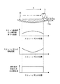
制御部は、スリットノズル3から曲面基材11に塗布液を吐出する際、スリットノズル3の移動速度(X方向)を、スリットノズル3のスリット先端部3aから曲面基材11の塗布面までの距離に反比例させるよう、スリットノズル3を制御する。図4は、曲面基材11上のスリットノズル3の位置に対する、スリット先端部3aから塗布面11aまでの距離、スリットノズル3の移動速度、スリットノズル3の吐出量又は吐出圧力の関係を示すグラフである。図4に示されるように、スリットノズル3のスリット先端部3aから曲面基材11の塗布面11aまでの距離Dは、曲面基材11のX方向基端部で最も短く、X方向中央部に向かって長くなり、X方向中央部で最も長くなり、X方向中央部からX方向先端部に向かって短くなり、X方向先端部で最も短くなる。そして、スリットノズル3のスリット先端部3aから曲面基材11の塗布面までの距離Dは、X方向基端部とX方向先端部とでは、同じとなる。したがって、スリットノズル3の移動速度は、曲面基材11のX方向基端部で最も速く、X方向中央部に向かって速度が減少し、X方向中央部で最も遅くなり、X方向中央部からX方向先端部に向かって速度が増加し、X方向先端部で最も速くなる。そして、スリットノズル3の移動速度は、X方向基端部とX方向先端部とでは、同じ速度となる。なお、塗布液の供給圧力又は供給量は、スリットノズル3の位置に関わらず一定となる。
When the controller discharges the coating liquid from the
前記構成の塗布装置10によれば、次のような効果を発揮できる。
According to the
(1)スリットノズル3への塗布液の供給圧力を一定にした状態で、スリットノズル3の移動速度を、スリット先端部3aから曲面基材11の塗布面11aまでの距離Dに反比例させるようにスリットノズル3を移動させることによって、曲面基材11に対して、塗布液の上面が平面となるよう塗布液を塗布することができる。
(1) In a state where the supply pressure of the coating liquid to the
(2)スリットノズル3への塗布液の供給量を一定にした状態で、スリットノズル3の移動速度を、スリット先端部3aから曲面基材11の塗布面11aまでの距離Dに反比例させるようにスリットノズル3を移動させることによって、曲面基材11に対して、塗布液の上面が平面となるよう塗布液を塗布することができる。
(2) In a state where the supply amount of the coating liquid to the
(3)曲面基材11の凹状曲面に塗布液として接着剤を塗布することによって、凹状曲面において接着剤の上面が平面となるよう接着剤を塗布することができる。その結果、凸状曲面ガラスと平面ガラスとの貼り合わせが容易となり、片側凸ガラスを容易に形成することができる。
(3) By applying an adhesive as a coating liquid to the concave curved surface of the
(4)塗布液がチキソ性を有していると、曲面基材11に塗布された塗布液の移動を抑制することができ、曲面基材11の所定の領域内に塗布液を平坦に塗布することができる。また、塗布液がチキソ性を有していると、吐出後の塗布液は粘度が高くなるため、曲面基材11に平面塗布する場合のように、塗布中に塗布する厚みが変化する場合であっても、厚みの厚いところから薄いところへ塗布液が流れて厚みが変化するということが発生しにくく、塗布液の上面を適切な平面に仕上げることができる。
(4) If the coating liquid has thixotropy, the movement of the coating liquid applied to the
(5)曲面基材11の凹状曲面が一定の曲率を有しているので、スリットノズル3の移動速度をスリット先端部3aから曲面基材11までの距離に反比例させることを、容易に達成できる。
(5) Since the concave curved surface of the
(6)スリットノズル3の先端部3aから曲面基材11の塗布面11aまでの距離Dが連続して変化する場合の他の塗布方法としては、スリットノズル3のX方向の移動速度を一定とし、塗布液の供給圧力又は供給量を、距離Dに比例させて塗布するという方法が考えられる。しかし、このような方法を行った場合、単位時間あたりの塗布量が変化し、塗布液が揮発して固化するまでにかかる時間が一定にならない(厚く塗布した場合は、揮発に時間がかかる)ため、曲面基材11の塗布面11における固化後の塗布液の品質の均一性が欠けるという問題がある。これに対して、本発明では、塗布液の供給圧力又は供給量を一定とするため、塗布のどの時点においても塗布液が固化するまでの時間を一定にでき、固化後の塗布液の品質の均一性を、塗布液の供給圧力又は供給量を距離Dに比例させて塗布する場合と比べて向上させることができるという効果を有している。
(6) As another coating method when the distance D from the
上記実施形態では、支持部材はノズル移動方向(X方向)に2つ設けられているが、1つ又は3以上設けられても良い。 In the above embodiment, two support members are provided in the nozzle movement direction (X direction), but one or three or more support members may be provided.
上記実施形態では、挟持部材と支持部材は、スリットノズル3のスリット方向(Y方向)における曲面基材11の両端部で、一対として設けられているが、挟持部材と支持部材は、Y方向において、所定間隔を有して、3以上設けられていても良い。
In the above embodiment, the sandwiching member and the support member are provided as a pair at both ends of the
上記実施形態では、曲面基材11が一定の曲率を有する凹形状を有しているが、曲面基材11の形状はそれに限定されず、例えば、図5に示されるように、全面が凸形状を有する曲面基材でもよく、また、図6に示されるように、X方向の途中で凸形状を有する曲面基材でもよい。
In the above embodiment, the
図5は、他の実施形態に係る曲面基材11上のスリットノズル3の位置に対する、スリット先端部3aから塗布面11aまでの距離、スリットノズル3の移動速度、スリットノズル3の吐出量又は吐出圧力の関係を示すグラフである。図5に示されるように、スリットノズル3のスリット先端部3aから曲面基材11の塗布面11aまでの距離Dは、曲面基材11のX方向基端部で最も長く、X方向中央部に向かって短くなり、X方向中央部で最も短くなり、X方向中央部からX方向先端部に向かって長くなり、X方向先端部で最も長くなる。そして、スリットノズル3のスリット先端部3aから曲面基材11の塗布面までの距離Dは、X方向基端部とX方向先端部とでは、同じとなる。したがって、スリットノズル3の移動速度は、曲面基材11のX方向基端部で最も遅く、X方向中央部に向かって速度が増加し、X方向中央部で最も速くなり、X方向中央部からX方向先端部に向かって速度が減少し、X方向先端部で最も遅くなる。そして、スリットノズル3の移動速度は、X方向基端部とX方向先端部とでは、同じ速度となる。なお、塗布液の供給圧力又は供給量は、スリットノズル3の位置に関わらず一定となる。
FIG. 5 shows the distance from the
図6は、他の実施形態に係る曲面基材11上のスリットノズル3の位置に対する、スリット先端部3aから塗布面11aまでの距離、スリットノズル3の移動速度、スリットノズル3の吐出量又は吐出圧力の関係を示すグラフである。図6に示されるように、スリットノズル3のスリット先端部3aから曲面基材11の塗布面11aまでの距離Dは、曲面基材11のX方向基端部からX方向に向かって長くなり、途中においてX方向中央部に向かって短くなり、さらに、X方向中央部からX方向に向かって長くなり、途中においてX方向先端部に向かって短くなる。そして距離Dは、X方向基端部とX方向先端部とでは、同じとなる。したがって、スリットノズル3の移動速度は、曲面基材11のX方向基端部からX方向に向かって遅くなり、途中においてX方向中央部に向かって速くなり、さらに、X方向中央部からX方向に向かって遅くなり、途中においてX方向先端部に向かって速くなる。なお、塗布液の供給圧力又は供給量は、スリットノズル3の位置に関わらず一定となる。
FIG. 6 shows the distance from the
また、図面は省略するが、スリットノズル3の先端部3aから曲面基材11の塗布面11aまでの距離Dに対してスリットノズル3の移動速度を反比例される制御においては、予め曲面基材11の形状が判明しておれば、それに合わせたプログラムでスリットノズル3を制御すればよく、また、曲面基材11毎に形状が異なる場合、スリットノズル3の進行方向前方に距離センサを設け、連続的にスリットノズル3の進行方向前方における距離Dを測定することによって、距離Dに対して反比例させた移動速度でスリットノズル3を移動させてもよく、またその他の方法を用いてもよい。
Although not shown, in the control in which the moving speed of the
また、上記実施形態では、供給部4の塗布液をスリットノズル3から吐出させる機構としては、シリンジポンプ44のように圧力によって吐出量(供給量)を変化させるもので説明しているが、ギヤポンプのように回転数で供給量を変化させるものでもよい。本発明では、これらの作動圧力や回転数を一定にすることによって、スリットノズル3からの供給量を一定にしている。
In the above embodiment, the mechanism for discharging the coating liquid of the supply unit 4 from the
特許請求の範囲に記載された本発明の精神及び範囲から逸脱することなく、各種変形及び変更を行うことも可能である。 Various modifications and changes can be made without departing from the spirit and scope of the invention as set forth in the appended claims.
本発明では、曲面基材へ塗布液を塗布するにあたり、塗布された塗布液の上面が平面となるような、塗布液の塗布装置及び塗布方法を提供することができるので、産業上の利用価値が大である。 In the present invention, when applying the coating liquid to the curved substrate, it is possible to provide a coating liquid coating apparatus and a coating method in which the top surface of the coated coating liquid is flat. Is big.
1 貯留タンク
2 保持トレイ
20 テーブル 201 ボールネジ 202 ハンドル 203 移動台
21 挟持部材 21a 鉛直部分 21b 水平部分
22 挟持部材
23 支持部材 23a 支持部 23b 付勢部材
24 支持部材
25 挟持部材 26 挟持部材 27 支持部材 28 支持部材
3 スリットノズル
3a スリット先端部 3b 吐出口
4 供給部
43 モータ 44 シリンジポンプ 45 第1供給管路
48 三方弁 49 第2供給管路
10 塗布装置
11 曲面基材
11a 塗布面
12 二方弁
D スリットノズルの先端部から曲面基材の塗布面までの距離DESCRIPTION OF SYMBOLS 1
23
48 Three-
Claims (5)
前記塗布液を貯留する貯留タンクと、
前記塗布液を前記曲面基材に塗布するスリットノズルと、
前記貯留タンクから前記スリットノズルへ前記塗布液を供給する供給部と、
前記塗布装置を制御する制御部と、を備えており、
前記制御部は、前記スリットノズルへの前記塗布液の供給圧力を一定とするよう前記供給部を制御し、さらに、前記スリットノズルの移動速度を、前記スリットノズルのスリット先端部から前記曲面基材の塗布面までの距離に反比例させるよう前記スリットノズルを制御することを特徴とする、塗布装置。
An apparatus for applying a coating liquid to a curved substrate,
A storage tank for storing the coating liquid;
A slit nozzle for applying the coating liquid to the curved substrate;
A supply unit for supplying the coating liquid from the storage tank to the slit nozzle;
A control unit for controlling the coating device,
The control unit controls the supply unit so as to make the supply pressure of the coating liquid to the slit nozzle constant, and further changes the moving speed of the slit nozzle from the slit tip of the slit nozzle to the curved base material. The coating device is characterized in that the slit nozzle is controlled to be inversely proportional to the distance to the coating surface.
前記塗布液を貯留する貯留タンクと、
前記塗布液を前記曲面基材に塗布するスリットノズルと、
前記貯留タンクから前記スリットノズルへ前記塗布液を供給する供給部と、
前記塗布装置を制御する制御部と、を備えており、
前記制御部は、前記スリットノズルへの前記塗布液の供給量を一定とするよう前記供給部を制御し、さらに、前記スリットノズルの移動速度を、前記スリットノズルのスリット先端部から前記曲面基材の塗布面までの距離に反比例させるよう前記スリットノズルを制御することを特徴とする、塗布装置。
An apparatus for applying a coating liquid to a curved substrate,
A storage tank for storing the coating liquid;
A slit nozzle for applying the coating liquid to the curved substrate;
A supply unit for supplying the coating liquid from the storage tank to the slit nozzle;
A control unit for controlling the coating device,
The control unit controls the supply unit so that a supply amount of the coating liquid to the slit nozzle is constant, and further controls the moving speed of the slit nozzle from the slit tip of the slit nozzle to the curved base material. The coating device is characterized in that the slit nozzle is controlled to be inversely proportional to the distance to the coating surface.
The coating apparatus of Claim 1 or 2 with which the application surface of the said curved base material has a concave curved surface.
前記塗布液を前記曲面基材に塗布するスリットノズルへの前記塗布液の供給圧力を一定とし、
前記スリットノズルの移動速度を、前記スリットノズルのスリット先端部から前記曲面基材の塗布面までの距離に反比例させて前記スリットノズルを移動させることを特徴とする、塗布方法。
A method of applying a coating liquid to a curved substrate,
The supply pressure of the coating liquid to the slit nozzle that applies the coating liquid to the curved substrate is constant,
The coating method, wherein the slit nozzle is moved in inverse proportion to the distance from the slit tip of the slit nozzle to the coating surface of the curved base material.
前記塗布液を前記曲面基材に塗布するスリットノズルへの前記塗布液の供給量を一定とし、
前記スリットノズルの移動速度を、前記スリットノズルのスリット先端部から前記曲面基材の塗布面までの距離に反比例させて前記スリットノズルを移動させることを特徴とする、塗布方法。A method of applying a coating liquid to a curved substrate,
The supply amount of the coating liquid to the slit nozzle for applying the coating liquid to the curved substrate is constant,
The coating method, wherein the slit nozzle is moved in inverse proportion to the distance from the slit tip of the slit nozzle to the coating surface of the curved base material.
Applications Claiming Priority (1)
| Application Number | Priority Date | Filing Date | Title |
|---|---|---|---|
| PCT/JP2016/059463 WO2017163381A1 (en) | 2016-03-24 | 2016-03-24 | Coating device and coating method for coating coating liquid on curved base material |
Publications (2)
| Publication Number | Publication Date |
|---|---|
| JP6318316B2 true JP6318316B2 (en) | 2018-04-25 |
| JPWO2017163381A1 JPWO2017163381A1 (en) | 2018-05-24 |
Family
ID=59900000
Family Applications (1)
| Application Number | Title | Priority Date | Filing Date |
|---|---|---|---|
| JP2018505041A Active JP6318316B2 (en) | 2016-03-24 | 2016-03-24 | Coating apparatus and coating method for coating liquid on curved substrate |
Country Status (5)
| Country | Link |
|---|---|
| JP (1) | JP6318316B2 (en) |
| KR (1) | KR101854103B1 (en) |
| CN (1) | CN107921461B (en) |
| TW (1) | TWI641427B (en) |
| WO (1) | WO2017163381A1 (en) |
Families Citing this family (2)
| Publication number | Priority date | Publication date | Assignee | Title |
|---|---|---|---|---|
| KR102353648B1 (en) * | 2020-10-21 | 2022-01-21 | 주식회사 나래나노텍 | Slot die coating device and method for printing substrate |
| KR102574214B1 (en) | 2021-11-17 | 2023-09-06 | 한국생산기술연구원 | Normal orientation method of nozzle for high curvature coating process and automatic coating apparatus to which this is applied |
Citations (7)
| Publication number | Priority date | Publication date | Assignee | Title |
|---|---|---|---|---|
| JP2002143752A (en) * | 2000-11-13 | 2002-05-21 | Tokyo Electron Ltd | Device for feeding coating fluid and device for coating |
| JP2003190862A (en) * | 2001-12-28 | 2003-07-08 | Dainippon Printing Co Ltd | Coating method and coating apparatus |
| JP2005125327A (en) * | 2004-12-20 | 2005-05-19 | Seiko Epson Corp | Method and apparatus for discharging liquid-like substance |
| JP2010036110A (en) * | 2008-08-05 | 2010-02-18 | Toyota Motor Corp | Nozzle for discharging of damping material, damping material coating apparatus, and damping material coating method |
| WO2010131580A1 (en) * | 2009-05-09 | 2010-11-18 | コニカミノルタホールディングス株式会社 | Coating method and organic electronic element |
| JP2013187236A (en) * | 2012-03-06 | 2013-09-19 | Tokyo Electron Ltd | Slit nozzle for manufacturing solar cell, and chemical solution applying device |
| JP3202751U (en) * | 2015-12-09 | 2016-02-18 | 金堂 義明 | Slit nozzle and chemical coating device |
Family Cites Families (8)
| Publication number | Priority date | Publication date | Assignee | Title |
|---|---|---|---|---|
| JP2630522B2 (en) * | 1991-10-18 | 1997-07-16 | 富士写真フイルム株式会社 | Coating method and device |
| JP3257340B2 (en) | 1995-05-24 | 2002-02-18 | 松下電器産業株式会社 | Liquid coating method, liquid coating apparatus and slit nozzle |
| JP2003071352A (en) | 2001-09-06 | 2003-03-11 | Matsushita Electric Ind Co Ltd | Method and apparatus for applying liquid to coating and method and apparatus for manufacturing cathode ray tube by using the same |
| JP2004167422A (en) * | 2002-11-21 | 2004-06-17 | Seiko Epson Corp | Application method and application device |
| JP4501382B2 (en) * | 2003-09-11 | 2010-07-14 | 株式会社豊田自動織機 | Defogger wire coating device |
| JP4229853B2 (en) * | 2004-02-06 | 2009-02-25 | Hoya株式会社 | Application method and spectacle lens manufacturing method |
| WO2010146928A1 (en) * | 2009-06-19 | 2010-12-23 | タツモ株式会社 | Substrate coating apparatus |
| US20130089657A1 (en) * | 2011-10-07 | 2013-04-11 | Sage Electrochromics, Inc. | Direct dispense device and method |
-
2016
- 2016-03-24 WO PCT/JP2016/059463 patent/WO2017163381A1/en active Application Filing
- 2016-03-24 KR KR1020187005573A patent/KR101854103B1/en active IP Right Grant
- 2016-03-24 CN CN201680049967.6A patent/CN107921461B/en not_active Expired - Fee Related
- 2016-03-24 JP JP2018505041A patent/JP6318316B2/en active Active
- 2016-06-02 TW TW105117413A patent/TWI641427B/en not_active IP Right Cessation
Patent Citations (7)
| Publication number | Priority date | Publication date | Assignee | Title |
|---|---|---|---|---|
| JP2002143752A (en) * | 2000-11-13 | 2002-05-21 | Tokyo Electron Ltd | Device for feeding coating fluid and device for coating |
| JP2003190862A (en) * | 2001-12-28 | 2003-07-08 | Dainippon Printing Co Ltd | Coating method and coating apparatus |
| JP2005125327A (en) * | 2004-12-20 | 2005-05-19 | Seiko Epson Corp | Method and apparatus for discharging liquid-like substance |
| JP2010036110A (en) * | 2008-08-05 | 2010-02-18 | Toyota Motor Corp | Nozzle for discharging of damping material, damping material coating apparatus, and damping material coating method |
| WO2010131580A1 (en) * | 2009-05-09 | 2010-11-18 | コニカミノルタホールディングス株式会社 | Coating method and organic electronic element |
| JP2013187236A (en) * | 2012-03-06 | 2013-09-19 | Tokyo Electron Ltd | Slit nozzle for manufacturing solar cell, and chemical solution applying device |
| JP3202751U (en) * | 2015-12-09 | 2016-02-18 | 金堂 義明 | Slit nozzle and chemical coating device |
Also Published As
| Publication number | Publication date |
|---|---|
| TWI641427B (en) | 2018-11-21 |
| JPWO2017163381A1 (en) | 2018-05-24 |
| KR20180026785A (en) | 2018-03-13 |
| WO2017163381A1 (en) | 2017-09-28 |
| CN107921461B (en) | 2019-08-20 |
| CN107921461A (en) | 2018-04-17 |
| TW201733686A (en) | 2017-10-01 |
| KR101854103B1 (en) | 2018-05-02 |
Similar Documents
| Publication | Publication Date | Title |
|---|---|---|
| JP6318316B2 (en) | Coating apparatus and coating method for coating liquid on curved substrate | |
| JP2798503B2 (en) | Liquid coating method and coating device | |
| TWI637790B (en) | Trace liquid dropping method and micro liquid dispenser | |
| CN104368506B (en) | Utilize the coating layer forming method and apparatus for coating of gap nozzle | |
| JP6318317B2 (en) | Curved substrate holding tray | |
| JP6295053B2 (en) | Coating apparatus and coating method | |
| JP5899424B2 (en) | Coating apparatus and coating method | |
| JP5405061B2 (en) | Coating equipment | |
| JP4197107B2 (en) | Coating equipment | |
| JP5253959B2 (en) | Coating device | |
| JP2009172556A (en) | Slit coat type coating device and coating method | |
| JP3811740B2 (en) | Coating equipment | |
| JP6856323B2 (en) | Coating device and coating method | |
| JP5465936B2 (en) | Liquid material discharging method, apparatus and program | |
| US10335920B2 (en) | Multiple nozzle slurry dispense scheme | |
| WO2015037121A1 (en) | Attaching device | |
| JP6203620B2 (en) | Coating equipment | |
| JP6185510B2 (en) | Micro liquid dispenser | |
| JP6528476B2 (en) | Coating apparatus and coating method | |
| JP4797458B2 (en) | Application method | |
| JP3546257B2 (en) | Coating device and method | |
| JPH1066911A (en) | Liquid coating method and device therefor | |
| WO2018062114A1 (en) | Microneedle array drug carrying method and drug carrying device | |
| JP2021084065A (en) | Applicator | |
| JP2020146871A (en) | Line drawing device and line drawing method for functional materials |
Legal Events
| Date | Code | Title | Description |
|---|---|---|---|
| A621 | Written request for application examination |
Free format text: JAPANESE INTERMEDIATE CODE: A621 Effective date: 20180131 |
|
| A871 | Explanation of circumstances concerning accelerated examination |
Free format text: JAPANESE INTERMEDIATE CODE: A871 Effective date: 20180131 |
|
| A975 | Report on accelerated examination |
Free format text: JAPANESE INTERMEDIATE CODE: A971005 Effective date: 20180314 |
|
| TRDD | Decision of grant or rejection written | ||
| A01 | Written decision to grant a patent or to grant a registration (utility model) |
Free format text: JAPANESE INTERMEDIATE CODE: A01 Effective date: 20180327 |
|
| A61 | First payment of annual fees (during grant procedure) |
Free format text: JAPANESE INTERMEDIATE CODE: A61 Effective date: 20180402 |
|
| R150 | Certificate of patent or registration of utility model |
Ref document number: 6318316 Country of ref document: JP Free format text: JAPANESE INTERMEDIATE CODE: R150 |