JP6313472B2 - Packaging assembly - Google Patents
Packaging assembly Download PDFInfo
- Publication number
- JP6313472B2 JP6313472B2 JP2016565253A JP2016565253A JP6313472B2 JP 6313472 B2 JP6313472 B2 JP 6313472B2 JP 2016565253 A JP2016565253 A JP 2016565253A JP 2016565253 A JP2016565253 A JP 2016565253A JP 6313472 B2 JP6313472 B2 JP 6313472B2
- Authority
- JP
- Japan
- Prior art keywords
- packaging assembly
- body part
- outer body
- cover member
- inner body
- Prior art date
- Legal status (The legal status is an assumption and is not a legal conclusion. Google has not performed a legal analysis and makes no representation as to the accuracy of the status listed.)
- Active
Links
Images


Classifications
-
- A—HUMAN NECESSITIES
- A24—TOBACCO; CIGARS; CIGARETTES; SIMULATED SMOKING DEVICES; SMOKERS' REQUISITES
- A24F—SMOKERS' REQUISITES; MATCH BOXES; SIMULATED SMOKING DEVICES
- A24F15/00—Receptacles or boxes specially adapted for cigars, cigarettes, simulated smoking devices or cigarettes therefor
- A24F15/01—Receptacles or boxes specially adapted for cigars, cigarettes, simulated smoking devices or cigarettes therefor specially adapted for simulated smoking devices or cigarettes therefor
-
- A—HUMAN NECESSITIES
- A24—TOBACCO; CIGARS; CIGARETTES; SIMULATED SMOKING DEVICES; SMOKERS' REQUISITES
- A24F—SMOKERS' REQUISITES; MATCH BOXES; SIMULATED SMOKING DEVICES
- A24F15/00—Receptacles or boxes specially adapted for cigars, cigarettes, simulated smoking devices or cigarettes therefor
- A24F15/12—Receptacles or boxes specially adapted for cigars, cigarettes, simulated smoking devices or cigarettes therefor for pocket use
-
- A—HUMAN NECESSITIES
- A45—HAND OR TRAVELLING ARTICLES
- A45C—PURSES; LUGGAGE; HAND CARRIED BAGS
- A45C11/00—Receptacles for purposes not provided for in groups A45C1/00-A45C9/00
- A45C11/24—Etuis for purposes not covered by a single one of groups A45C11/02 - A45C11/22, A45C11/26, A45C11/32 - A45C11/38
-
- A—HUMAN NECESSITIES
- A45—HAND OR TRAVELLING ARTICLES
- A45C—PURSES; LUGGAGE; HAND CARRIED BAGS
- A45C13/00—Details; Accessories
-
- A—HUMAN NECESSITIES
- A45—HAND OR TRAVELLING ARTICLES
- A45C—PURSES; LUGGAGE; HAND CARRIED BAGS
- A45C13/00—Details; Accessories
- A45C13/005—Hinges
-
- A—HUMAN NECESSITIES
- A45—HAND OR TRAVELLING ARTICLES
- A45C—PURSES; LUGGAGE; HAND CARRIED BAGS
- A45C13/00—Details; Accessories
- A45C13/005—Hinges
- A45C13/007—Hinges with spring means
-
- A—HUMAN NECESSITIES
- A45—HAND OR TRAVELLING ARTICLES
- A45D—HAIRDRESSING OR SHAVING EQUIPMENT; EQUIPMENT FOR COSMETICS OR COSMETIC TREATMENTS, e.g. FOR MANICURING OR PEDICURING
- A45D40/00—Casings or accessories specially adapted for storing or handling solid or pasty toiletry or cosmetic substances, e.g. shaving soaps or lipsticks
- A45D40/02—Casings wherein movement of the lipstick or like solid is a sliding movement
- A45D40/023—Casings wherein movement of the lipstick or like solid is a sliding movement with self-contained covering means
-
- B—PERFORMING OPERATIONS; TRANSPORTING
- B65—CONVEYING; PACKING; STORING; HANDLING THIN OR FILAMENTARY MATERIAL
- B65D—CONTAINERS FOR STORAGE OR TRANSPORT OF ARTICLES OR MATERIALS, e.g. BAGS, BARRELS, BOTTLES, BOXES, CANS, CARTONS, CRATES, DRUMS, JARS, TANKS, HOPPERS, FORWARDING CONTAINERS; ACCESSORIES, CLOSURES, OR FITTINGS THEREFOR; PACKAGING ELEMENTS; PACKAGES
- B65D25/00—Details of other kinds or types of rigid or semi-rigid containers
- B65D25/02—Internal fittings
- B65D25/10—Devices to locate articles in containers
- B65D25/108—Devices, e.g. plates, presenting apertures through which the articles project
-
- B—PERFORMING OPERATIONS; TRANSPORTING
- B65—CONVEYING; PACKING; STORING; HANDLING THIN OR FILAMENTARY MATERIAL
- B65D—CONTAINERS FOR STORAGE OR TRANSPORT OF ARTICLES OR MATERIALS, e.g. BAGS, BARRELS, BOTTLES, BOXES, CANS, CARTONS, CRATES, DRUMS, JARS, TANKS, HOPPERS, FORWARDING CONTAINERS; ACCESSORIES, CLOSURES, OR FITTINGS THEREFOR; PACKAGING ELEMENTS; PACKAGES
- B65D25/00—Details of other kinds or types of rigid or semi-rigid containers
- B65D25/34—Coverings or external coatings
-
- B—PERFORMING OPERATIONS; TRANSPORTING
- B65—CONVEYING; PACKING; STORING; HANDLING THIN OR FILAMENTARY MATERIAL
- B65D—CONTAINERS FOR STORAGE OR TRANSPORT OF ARTICLES OR MATERIALS, e.g. BAGS, BARRELS, BOTTLES, BOXES, CANS, CARTONS, CRATES, DRUMS, JARS, TANKS, HOPPERS, FORWARDING CONTAINERS; ACCESSORIES, CLOSURES, OR FITTINGS THEREFOR; PACKAGING ELEMENTS; PACKAGES
- B65D25/00—Details of other kinds or types of rigid or semi-rigid containers
- B65D25/38—Devices for discharging contents
-
- B—PERFORMING OPERATIONS; TRANSPORTING
- B65—CONVEYING; PACKING; STORING; HANDLING THIN OR FILAMENTARY MATERIAL
- B65D—CONTAINERS FOR STORAGE OR TRANSPORT OF ARTICLES OR MATERIALS, e.g. BAGS, BARRELS, BOTTLES, BOXES, CANS, CARTONS, CRATES, DRUMS, JARS, TANKS, HOPPERS, FORWARDING CONTAINERS; ACCESSORIES, CLOSURES, OR FITTINGS THEREFOR; PACKAGING ELEMENTS; PACKAGES
- B65D43/00—Lids or covers for rigid or semi-rigid containers
- B65D43/14—Non-removable lids or covers
- B65D43/16—Non-removable lids or covers hinged for upward or downward movement
- B65D43/163—Non-removable lids or covers hinged for upward or downward movement the container and the lid being made separately
- B65D43/164—Non-removable lids or covers hinged for upward or downward movement the container and the lid being made separately and connected by interfitting hinge elements integrally with the container and the lid formed respectively
- B65D43/165—Non-removable lids or covers hinged for upward or downward movement the container and the lid being made separately and connected by interfitting hinge elements integrally with the container and the lid formed respectively these elements being assembled by a separate pin-like member
-
- B—PERFORMING OPERATIONS; TRANSPORTING
- B65—CONVEYING; PACKING; STORING; HANDLING THIN OR FILAMENTARY MATERIAL
- B65D—CONTAINERS FOR STORAGE OR TRANSPORT OF ARTICLES OR MATERIALS, e.g. BAGS, BARRELS, BOTTLES, BOXES, CANS, CARTONS, CRATES, DRUMS, JARS, TANKS, HOPPERS, FORWARDING CONTAINERS; ACCESSORIES, CLOSURES, OR FITTINGS THEREFOR; PACKAGING ELEMENTS; PACKAGES
- B65D43/00—Lids or covers for rigid or semi-rigid containers
- B65D43/14—Non-removable lids or covers
- B65D43/16—Non-removable lids or covers hinged for upward or downward movement
- B65D43/163—Non-removable lids or covers hinged for upward or downward movement the container and the lid being made separately
- B65D43/166—Non-removable lids or covers hinged for upward or downward movement the container and the lid being made separately and connected by separate interfitting hinge elements fixed to the container and the lid respectively
-
- B—PERFORMING OPERATIONS; TRANSPORTING
- B65—CONVEYING; PACKING; STORING; HANDLING THIN OR FILAMENTARY MATERIAL
- B65D—CONTAINERS FOR STORAGE OR TRANSPORT OF ARTICLES OR MATERIALS, e.g. BAGS, BARRELS, BOTTLES, BOXES, CANS, CARTONS, CRATES, DRUMS, JARS, TANKS, HOPPERS, FORWARDING CONTAINERS; ACCESSORIES, CLOSURES, OR FITTINGS THEREFOR; PACKAGING ELEMENTS; PACKAGES
- B65D43/00—Lids or covers for rigid or semi-rigid containers
- B65D43/14—Non-removable lids or covers
- B65D43/20—Non-removable lids or covers linearly slidable
-
- B—PERFORMING OPERATIONS; TRANSPORTING
- B65—CONVEYING; PACKING; STORING; HANDLING THIN OR FILAMENTARY MATERIAL
- B65D—CONTAINERS FOR STORAGE OR TRANSPORT OF ARTICLES OR MATERIALS, e.g. BAGS, BARRELS, BOTTLES, BOXES, CANS, CARTONS, CRATES, DRUMS, JARS, TANKS, HOPPERS, FORWARDING CONTAINERS; ACCESSORIES, CLOSURES, OR FITTINGS THEREFOR; PACKAGING ELEMENTS; PACKAGES
- B65D43/00—Lids or covers for rigid or semi-rigid containers
- B65D43/14—Non-removable lids or covers
- B65D43/24—Devices for retaining in open position
-
- B—PERFORMING OPERATIONS; TRANSPORTING
- B65—CONVEYING; PACKING; STORING; HANDLING THIN OR FILAMENTARY MATERIAL
- B65D—CONTAINERS FOR STORAGE OR TRANSPORT OF ARTICLES OR MATERIALS, e.g. BAGS, BARRELS, BOTTLES, BOXES, CANS, CARTONS, CRATES, DRUMS, JARS, TANKS, HOPPERS, FORWARDING CONTAINERS; ACCESSORIES, CLOSURES, OR FITTINGS THEREFOR; PACKAGING ELEMENTS; PACKAGES
- B65D43/00—Lids or covers for rigid or semi-rigid containers
- B65D43/26—Mechanisms for opening or closing, e.g. pedal-operated
-
- B—PERFORMING OPERATIONS; TRANSPORTING
- B65—CONVEYING; PACKING; STORING; HANDLING THIN OR FILAMENTARY MATERIAL
- B65D—CONTAINERS FOR STORAGE OR TRANSPORT OF ARTICLES OR MATERIALS, e.g. BAGS, BARRELS, BOTTLES, BOXES, CANS, CARTONS, CRATES, DRUMS, JARS, TANKS, HOPPERS, FORWARDING CONTAINERS; ACCESSORIES, CLOSURES, OR FITTINGS THEREFOR; PACKAGING ELEMENTS; PACKAGES
- B65D85/00—Containers, packaging elements or packages, specially adapted for particular articles or materials
- B65D85/20—Containers, packaging elements or packages, specially adapted for particular articles or materials for incompressible or rigid rod-shaped or tubular articles
Description
本発明は、包装される物品のための包装組立体及びそのような物品のパックに関する。 The present invention relates to a packaging assembly for an article to be packaged and a pack of such article.
本発明の包装組立体は、電子的蒸気送配システム、電子タバコ又は「e−シガレット」等としても知られる吸入器を包装するのに特に適している。したがって、本発明は、詳しくはこれらの物品パックもまた提供する。しかしながら、重要なことに、本発明の包装組立体は、このような特定の包装用途に限定されず、他の物品の範囲に適していてもよく、該物品の範囲のために採用されてもよい。 The packaging assembly of the present invention is particularly suitable for packaging inhalers, also known as electronic vapor delivery systems, electronic cigarettes or “e-cigarettes” and the like. Accordingly, the present invention specifically provides these article packs as well. Importantly, however, the packaging assembly of the present invention is not limited to such specific packaging applications, and may be suitable for a range of other articles and employed for the scope of the article. Good.
個人用バポライザー、e−シガレット及び電子的蒸気送配システムのような上述のタイプの吸入器は、タバコ、シガリロ、シガー等のような旧来の喫煙物品の代替物として提案されている。これらの吸入器はまだ市場では比較的新しいが、吸入器のための新規な利便性に優れた包装構想を開発するための取り組みが既になされている。そのような包装構想の一例は、WO2013/142671A1に記載されている。 Inhalers of the type described above, such as personal vaporizers, e-cigarettes and electronic vapor delivery systems, have been proposed as alternatives to traditional smoking articles such as cigarettes, cigarillos, cigars and the like. Although these inhalers are still relatively new in the market, efforts have already been made to develop new and convenient packaging concepts for inhalers. An example of such a packaging concept is described in WO2013 / 142671A1.
本発明は、e−シガレット又は個人用バポライザーのような吸入器に特に適した、新規な利便性に優れた使い勝手のよい包装構想を提供するという課題に関する。 The present invention relates to the problem of providing a novel and convenient and easy-to-use packaging concept particularly suitable for inhalers such as e-cigarettes or personal vaporizers.
本発明によれば、請求項1に記載の特徴を有する包装組立体が提供される。本発明の多くの好ましい及び/又は有利な特徴は、従属請求項に記載される。
According to the present invention, a packaging assembly having the features of
したがって、一態様によれば、本発明は、1つ以上の物品を包装するための包装組立体であって、
物品を受容するための少なくとも1つの内部区画を画定する内側本体部、
内側本体部を少なくとも部分的に取り囲む外側本体部、及び、
少なくとも1つの内部区画へのアクセスを防止する閉位置と少なくとも1つの内部区画へのアクセスを可能にする開位置との間を移動可能なカバー部材を備えており、
外側本体部は、閉位置と開位置との間でカバー部材を移動させるために、内側本体部に対して第1位置と第2位置との間で移動可能である、包装組立体を提供する。
Thus, according to one aspect, the present invention is a packaging assembly for packaging one or more articles comprising:
An inner body defining an at least one internal compartment for receiving an article;
An outer body portion at least partially surrounding the inner body portion; and
A cover member movable between a closed position preventing access to at least one internal compartment and an open position allowing access to at least one internal compartment;
The outer body provides a packaging assembly that is movable between a first position and a second position with respect to the inner body to move the cover member between a closed position and an open position. .
このようにして、本発明は、内部区画に収容された1つ以上の物品へのアクセスを可能にする又は防止するようにカバー部材を開閉するためのシンプルで利便性に優れた機構を備えた包装組立体を提供する。これにより、使用者が包装組立体を取り扱う際、使用者は、その内容物にアクセスするために、さらにカバー部材を直接取り扱う必要がない。それどころか、単に包装組立体の外側本体部を取り扱うだけで、使用者は外側本体部を内側本体部に対して手動で動かすことによりカバー部材を開くことができる。 Thus, the present invention comprises a simple and convenient mechanism for opening and closing the cover member to enable or prevent access to one or more articles contained in the internal compartment. A packaging assembly is provided. Thus, when the user handles the packaging assembly, the user does not need to handle the cover member directly in order to access the contents. On the contrary, simply by handling the outer body part of the packaging assembly, the user can open the cover member by manually moving the outer body part relative to the inner body part.
特に好ましい実施形態では、包装組立体の外側本体部は、使用者によって把持及び/又は保持されるように構成される。この目的のため、外側本体部は、使用者による外側本体部の快適かつ安全な取り扱いを促進するためのグリップ部を含んでいてもよく、例えば、1つ以上のグリップ要素を有していてもよい。これにより、グリップ部、例えば1つ以上のグリップ要素は、外側本体部が内側本体部に対して手動で動くことを容易にし得る。この目的のため、任意のグリップ要素を含むグリップ部は、例えば、外側本体部における使用者のグリップを強化するために、曲面外形を有していてもよく、及び/又は、比較的軟質又は弾力性のある合成材料を含んでいてもよい。 In particularly preferred embodiments, the outer body portion of the packaging assembly is configured to be grasped and / or held by a user. For this purpose, the outer body part may include a grip part for facilitating the comfortable and safe handling of the outer body part by the user, for example having one or more grip elements. Good. Thereby, the grip part, for example one or more grip elements, may facilitate the manual movement of the outer body part relative to the inner body part. For this purpose, the grip part including any grip elements may have a curved profile and / or be relatively soft or elastic, for example to enhance the user's grip on the outer body part. It may contain a synthetic material.
好ましい実施形態では、内側本体部は、少なくとも1つの内部区画内に1つ以上の細長い物品を収容するように構成されている。この点において、各内部区画は、好ましくは、1つ以上のe−シガレットを収容して保持するように構成される。さらに、内側本体部は、(例えば、外側本体部に関する)包装組立体内に構成及び配置されてもよい。これにより、外側本体部が内側本体部に対して第2位置に移動させられた際に、物品の提供又は提示がカバー部材の開口によって行われる又はなされる。このようにして、包装組立体は、物品のパックを開閉するためのシンプルで利便性に優れた機構を提供するだけでなく、包装体が開かれた際にそれらの物品を使用者に提供又は提示するように構成することもできる。 In a preferred embodiment, the inner body portion is configured to accommodate one or more elongated articles within at least one internal compartment. In this regard, each internal compartment is preferably configured to receive and hold one or more e-cigarettes. Further, the inner body portion may be configured and disposed within the packaging assembly (eg, with respect to the outer body portion). Thereby, when the outer body part is moved to the second position with respect to the inner body part, provision or presentation of the article is or is made by the opening of the cover member. In this way, the packaging assembly not only provides a simple and convenient mechanism for opening and closing a pack of articles, but also provides the articles to the user when the packaging is opened or It can also be configured to present.
好ましい実施形態では、包装組立体は、カバー部材が開位置にある際に、少なくとも1つの内側区画内の1つ以上の細長い物品が内側本体部から不意に落下するのを抑制又は防止するための保持手段を含んでいる。この点において、保持手段は、望ましくは内部区画内に配置され、好ましくは、物品と接触して、該内部区画から物品が取り除かれることに対する抵抗(例えば、摩擦抵抗)を付与するように構成されている。有利には、保持手段は、物品と接触して物品の移動に対する摩擦抵抗を提供するために、内部区画に設けられた繊維又は起毛を含んでいてもよい。あるいは又はこれに加えて、保持手段は、物品を不意に取り除かれないように保持する顎部材を含んでもよい。 In a preferred embodiment, the packaging assembly is for inhibiting or preventing one or more elongated articles in the at least one inner compartment from unexpectedly falling from the inner body portion when the cover member is in the open position. Includes holding means. In this regard, the retaining means is desirably disposed within the interior compartment and is preferably configured to contact the article and provide resistance (eg, frictional resistance) against removal of the article from the interior compartment. ing. Advantageously, the holding means may include fibers or raised in the inner compartment to contact the article and provide frictional resistance against movement of the article. Alternatively or in addition, the holding means may include a jaw member that holds the article against accidental removal.
好ましい実施形態では、包装組立体は、外側本体部の開口及び/又は内側本体部の内部区画の閉位置における実質的な気密閉塞又は気密封止を形成するように構成された封止要素を含んでいる。封止要素は、カバー部材の内面に形成され、又は、設けられていてもよい。カバー部材自体は、蓋又はキャップの形態で、例えば包装組立体の上端領域に設けられていてもよい。これにより、封止要素は、蓋又はキャップが閉位置にある際に外側本体部及び/又は内側本体部に対して封止するため、蓋又はキャップの縁又はリムにおいて又はその周囲に配置されていてもよい。あるいは、封止要素は、外側本体部及び/又は内側本体部の上方リム又は上縁に(例えば、封止ガスケットとして)設けられていてもよい。 In a preferred embodiment, the packaging assembly includes a sealing element configured to form a substantially hermetic closure or hermetic seal in the closed position of the opening of the outer body portion and / or the inner compartment of the inner body portion. It is out. The sealing element may be formed or provided on the inner surface of the cover member. The cover member itself may be provided in the form of a lid or cap, for example in the upper end region of the packaging assembly. Thereby, the sealing element is arranged at or around the edge or rim of the lid or cap for sealing against the outer body part and / or the inner body part when the lid or cap is in the closed position. May be. Alternatively, the sealing element may be provided on the upper rim or upper edge of the outer body part and / or the inner body part (eg as a sealing gasket).
好ましい実施形態では、カバー部材は、外側本体部に連結されており、外側本体部が内側本体部に対して第1位置から第2位置に移動させられる際に、閉位置から開位置に移動するように構成されている。より詳細には、カバー部材は、好ましくは、外側本体部が内側本体部に対して第1位置と第2位置との間で移動する際にカバー部材もまた閉位置と開位置との間で枢動するように、例えばヒンジ連結部を介して、外側本体部に枢支連結されている。この点に関して、カバー部材は、外側本体部に外側枢軸を介して枢支連結されている。 In a preferred embodiment, the cover member is coupled to the outer body portion and moves from the closed position to the open position when the outer body portion is moved from the first position to the second position with respect to the inner body portion. It is configured as follows. More particularly, the cover member is preferably also between the closed position and the open position when the outer body portion moves between the first position and the second position relative to the inner body portion. In order to pivot, it is pivotally connected to the outer body part, for example, via a hinge connection part. In this regard, the cover member is pivotally connected to the outer body portion via the outer pivot.
本発明の特に好ましい実施形態では、カバー部材は、内側本体部に(例えば、ヒンジ連結部を介して)枢支連結されており、それによってカバー部材が内側本体部に対して閉位置と開位置との間で枢動する。これにより、カバー部材は、内側本体部に内側枢軸を介して枢支連結される。したがって、カバー部材は、内側本体部と外側本体部との両方に枢支連結されていてもよい。その場合、内側枢軸は、典型的には、外側枢軸に対して実質的に平行であるが、外側枢軸から横方向及び/又は内方にずれている。また、内側枢軸及び外側枢軸のうち一方は、好ましくは、内側本体部又は外側本体部のそれぞれに対して変位可能である。 In a particularly preferred embodiment of the invention, the cover member is pivotally connected to the inner body part (eg via a hinge connection) so that the cover member is in the closed and open positions relative to the inner body part. Pivot between. Thus, the cover member is pivotally connected to the inner body portion via the inner pivot. Therefore, the cover member may be pivotally connected to both the inner body part and the outer body part. In that case, the inner pivot is typically substantially parallel to the outer pivot but offset laterally and / or inwardly from the outer pivot. Also, one of the inner pivot and the outer pivot is preferably displaceable with respect to each of the inner body part or the outer body part.
好ましい実施形態では、外側本体部は、内側本体部に対して第1位置と第2位置との間で並進移動又は摺動移動するように構成されている。これにより、使用者は、外側本体部を把持して、外側本体部を第1位置と第2位置との間で移動させるために内側本体部に対して摺動又は変位(例えば、並進)させることができる。好ましい実施形態では、外側本体部が包装体の上部を形成すると共に内側本体部が包装の下部又は底部を形成しており、それによって、並進相対運動は、外側本体部に下向きの圧力を付与することにより及ぼされ得る。あるいは又はそれに加えて、外側本体部は、内側本体部に対して第1位置と第2位置との間で回転運動又は回動運動するように構成されていてもよい。 In a preferred embodiment, the outer body portion is configured to translate or slide between a first position and a second position relative to the inner body portion. Thereby, the user grasps the outer body part and slides or displaces (for example, translates) the inner body part to move the outer body part between the first position and the second position. be able to. In a preferred embodiment, the outer body part forms the upper part of the package and the inner body part forms the lower or bottom part of the package, whereby the translational relative movement applies a downward pressure on the outer body part. Can be affected. Alternatively or in addition, the outer body portion may be configured to rotate or rotate between the first position and the second position with respect to the inner body portion.
好ましい実施形態では、内側本体部が、物品を受容するための少なくとも1つの内部区画を画定する内側筐体を形成しており、外側本体部が内側筐体を(例えば、スリーブ方式で)包囲する又は取り囲む外側筐体を形成している。これにより、外側筐体は、(1つ以上の)物品を受容及び収容する内側筐体に対して移動させられるように、すなわち、並進及び/又は回転するように構成されていてもよい。特に好ましい実施形態では、内側本体部と外側本体とが併せて包装組立体の容器を形成しており、カバー部材は容器を開閉するように移動可能である。 In a preferred embodiment, the inner body portion forms an inner housing defining at least one internal compartment for receiving an article, and the outer body portion surrounds the inner housing (eg, in a sleeve manner). Or the surrounding outer casing is formed. Thereby, the outer housing may be configured to be moved, i.e. translated and / or rotated, relative to the inner housing that receives and houses the article (s). In a particularly preferred embodiment, the inner body portion and the outer body together form a container for the packaging assembly, and the cover member is movable to open and close the container.
好ましい実施形態では、包装組立体は、内側本体部に対して外側本体部を第1位置に向かって付勢又は押勢するように構成及び配置された付勢手段、例えば少なくとも1つのばね部材をさらに含んでいてもよい。これにより、外側本体部の内側本体部に対する第1位置から第2位置への移動は、この付勢又は力(例えば、ばね付勢)に抗して行われる。換言すれば、包装組立体は、外側本体部を第1位置に戻すように作用させる又はそのように機能する。 In a preferred embodiment, the packaging assembly includes a biasing means, such as at least one spring member, configured and arranged to bias or bias the outer body portion toward the first position relative to the inner body portion. Further, it may be included. Thereby, the movement from the first position to the second position of the outer main body portion with respect to the inner main body portion is performed against this bias or force (for example, spring bias). In other words, the packaging assembly acts or functions to return the outer body portion to the first position.
特に好ましい実施形態では、内側本体部及び外側本体部のいずれか又は両方は、第1及び第2位置を画定するように構成された止め手段であって、外側本体部が内側本体部に対して移動することをそれらの第1位置と第2位置との間で止める又はその間に制限するように機能する止め手段を含んでいる。各止め手段は、典型的には、第1及び第2位置でのさらなる相対移動を防止するように相互作用又は相互係合する1つ以上の当接部材、例えば突起又は肩部を備えている。 In particularly preferred embodiments, either or both of the inner body portion and the outer body portion are stop means configured to define first and second positions, wherein the outer body portion is relative to the inner body portion. Stopping means are included which serve to stop or limit movement between their first and second positions. Each stop means typically comprises one or more abutment members, such as protrusions or shoulders, that interact or interengage to prevent further relative movement in the first and second positions. .
好ましい実施形態では、内側及び外側本体部は、内側部に対して外側本体部が第2位置に移動させられた際に、互いに係合して解放可能に相互係止することによりカバー部材を開位置に保持するよう構成及び配置された相補的な掛止手段を含んでいる。これに関し、相補的な掛止手段は、外側本体部の内側部又は内表面に設けられた少なくとも1つの第1掛止要素と、内側本体部の外側部又は外表面に設けられた少なくとも1つの相補的な第2掛止要素とを含む。相補的な掛止手段の第1及び第2掛止要素は、外側本体部が第2位置に移動させられた際に、互いに係合して解放可能に相互係止するように構成され、好ましくは、内側本体部(例えば、その端部)に外側本体部に対して所定の圧力又は牽引力が加えられた際に、双方より係合解除又は解放されるようにも構成される。例えば、包装組立体が使用者の手に保持されているとき、物品を内部区画に挿入することにより、相補的な掛止手段を係合解除させるように作用する力を内側本体部が加えられてもよい。このとき、外側本体部は、物品が区画に導入された際に、内側本体部に対して(例えば、ばね付勢の作用下で)第2位置から第1位置に戻るように移動し、それによってカバー部材を開位置から閉位置に戻すように移動させてもよい。使用者の手に保持された外側本体部に対して内側本体部に作用する物品(例えば、e−シガレット)の重量であっても、相補的な掛止手段を係合解除又は解放するのに十分であり得る。各物品又はe−シガレットは、数グラムの質量を有していてもよく、例えば、4g又は5gの質量を有していてもよい。第1及び第2掛止要素のうち1つ以上は、それらの相互係止及び/又は解放を容易にするために、変形可能又は撓み可能であってもよい。 In a preferred embodiment, the inner and outer body portions engage each other and releasably interlock when the outer body portion is moved to the second position relative to the inner portion to open the cover member. Complementary latching means constructed and arranged to hold in position is included. In this regard, the complementary latching means comprises at least one first latching element provided on the inner or inner surface of the outer body part and at least one provided on the outer or outer surface of the inner body part. And a complementary second latching element. The first and second latching elements of the complementary latching means are configured to engage and releasably interlock with each other when the outer body portion is moved to the second position, preferably Is configured to be disengaged or released from both sides when a predetermined pressure or traction force is applied to the outer body part on the inner body part (for example, its end). For example, when the packaging assembly is held in the user's hand, the inner body portion is applied with a force that acts to disengage the complementary latching means by inserting the article into the inner compartment. May be. At this time, when the article is introduced into the compartment, the outer body moves relative to the inner body (for example, under the action of a spring bias) so as to return from the second position to the first position. The cover member may be moved so as to return from the open position to the closed position. To disengage or release complementary latching means, even with the weight of an article (eg, e-cigarette) acting on the inner body relative to the outer body held in the user's hand May be sufficient. Each article or e-cigarette may have a mass of a few grams, for example a mass of 4 g or 5 g. One or more of the first and second latching elements may be deformable or deflectable to facilitate their interlocking and / or release.
したがって、特に好ましい実施形態では、第1掛止要素は、カバー部材を開位置に保持するために、外側本体部が内側本体部に対して第2位置に移動させられた際に第2掛止要素の相補的な第2係止面と協同して該第2係止面に当接する第1係止面を有する。この目的のため、第1及び第2掛止要素の係止面は、典型的には互いに当接している又はもたれかかっている。第1掛止要素はまた、外側本体部が内側本体部に対して第2位置に向かって移動する際に第2掛止要素の第2傾斜面と協同する第1傾斜面を有していてもよい。第1傾斜面及び第1係止面は、好ましくは共通平面から互いに収斂していてもよく、このとき第2傾斜面と第2係止面もまた、共通平面から互いに収斂していてもよい。 Thus, in a particularly preferred embodiment, the first latching element has a second latch when the outer body part is moved to the second position relative to the inner body part to hold the cover member in the open position. A first locking surface that abuts the second locking surface in cooperation with a complementary second locking surface of the element; For this purpose, the locking surfaces of the first and second latching elements are typically abutting or leaning against each other. The first hooking element also has a first inclined surface that cooperates with the second inclined surface of the second hooking element when the outer body portion moves toward the second position relative to the inner body portion. Also good. The first inclined surface and the first locking surface may preferably converge from a common plane, and at this time, the second inclined surface and the second locking surface may also converge from the common plane. .
特に好ましい実施形態では、内側本体部、外側本体部、及びカバー部材は、ポリエチレン、ポリプロピレン又はポリウレタンのようなポリマープラスチック材料から作製されており、好ましくは射出成形されている。 In a particularly preferred embodiment, the inner body part, the outer body part and the cover member are made from a polymer plastic material such as polyethylene, polypropylene or polyurethane, and are preferably injection molded.
別の態様では、本発明は、上述の実施形態のいずれか1つに係る包装組立体を有する、e−シガレットのような物品のパックを提供する。すなわち、物品パックは、
物品を収容する1つの内部区画又は複数の内部区画を画定する内側本体部、
内側本体部を少なくとも部分的に包囲する又は取り囲む外側本体部、及び、
(1つ又は複数の)内部区画へのアクセスを防止するための閉位置と(1つ又は複数の)内部区画へのアクセスを可能にするための開位置との間を移動可能なカバー部材を備えており、
外側本体部は、閉位置と開位置との間でカバー部材を移動させるために、内側本体部に対して第1位置と第2位置との間で移動可能である、包装組立体を含んでいる。
In another aspect, the present invention provides a pack of articles, such as an e-cigarette, having a packaging assembly according to any one of the above embodiments. That is, the goods pack is
An inner body defining an interior compartment or a plurality of interior compartments for containing articles;
An outer body that at least partially surrounds or surrounds the inner body, and
A cover member movable between a closed position to prevent access to the internal compartment (s) and an open position to allow access to the internal compartment (s); With
The outer body includes a packaging assembly that is movable between a first position and a second position relative to the inner body to move the cover member between a closed position and an open position. Yes.
本発明及びその利点のより詳細な理解のため、以下の説明において添付の図面を参照しつつ、本発明の例示の実施形態についてより詳細に説明する。これらの図面において、同様の参照符号は同様の部分を示す。 For a more detailed understanding of the present invention and its advantages, exemplary embodiments of the present invention will be described in more detail in the following description with reference to the accompanying drawings. In these drawings, like reference numerals designate like parts.
添付の図面は、本発明のさらなる理解を提供するために本明細書に含まれ及び組み込まれると共に、本明細書の一部を構成する。これらの図面は、本発明の特定の実施形態を示し、本明細書と併せて本発明の原理を説明するのに役立つ。本発明の他の実施形態及び本発明の多くの付随する利点は、以下の詳細な説明を参照してよりよく理解されることが容易に認識される。 The accompanying drawings are included and incorporated in and constitute a part of this specification to provide a further understanding of the invention. These drawings illustrate certain embodiments of the invention and, together with the description, serve to explain the principles of the invention. It will be readily appreciated that other embodiments of the present invention and many of the attendant advantages of the present invention will be better understood with reference to the following detailed description.
実施形態の図のさらなる抽象化を容易にするため、商業的に実施可能な実施形態において有用又は必須であり得る共通かつ/又は十分に理解されている要素は、必ずしも示されていないことが認識される。これらの図面の要素は、必ずしも互いに対して縮尺通りに図示されていない。方法の実施形態における所定の動作及び/又はステップは、特定の発生順序において記載または描写され得るが、当業者はこのような順序に関する特定性は実際には要求されないことを理解するということが認識される。本明細書で使用される用語及び表現は、特定の意味が本明細書中に定められている場合を除き、それらの対応するそれぞれの調査分野及び研究分野に関してそのような用語及び表現に与えられている通常の意味を有することもまた理解される。 It is recognized that common and / or well-understood elements that may be useful or essential in commercially feasible embodiments are not necessarily shown in order to facilitate further abstraction of the drawings of the embodiments. Is done. Elements of these drawings are not necessarily shown to scale relative to each other. It will be appreciated that although certain operations and / or steps in method embodiments may be described or depicted in a particular order of occurrence, those skilled in the art will appreciate that no particularity regarding such order is actually required. Is done. The terms and expressions used herein are given to such terms and expressions with respect to their respective respective research and research areas, unless specific meanings are set forth herein. It is also understood to have the usual meaning.
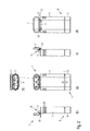
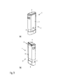
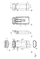
まず、図1(a)〜図1(e)及び図2(a)〜図2(e)を参照すると、特に好ましい実施形態に係る包装組立体1が一連の五面図に示される。図1(a)〜図1(e)は、閉じた状態の包装組立体1を示しており、図2(a)〜図2(e)は、開いた状態の包装組立体1を示している。また、同じ包装組立体1は、図3(a)及び図3(b)の斜視図並びに図4及び図5の分解図に示されている。
First, referring to FIGS. 1 (a) to 1 (e) and FIGS. 2 (a) to 2 (e), a
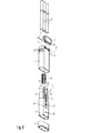
特に、図4及び図5から明らかなように、本実施形態の包装組立体1は、e−シガレットなどの細長い円筒形状の物品Cのために具体的に設計されている。この目的のため、包装組立体1は、内側筐体の形態である内側本体部2を含んでおり、内側本体部2は、3つ並んだ筒状収容体3を含んでいる。各筒状主要体3はそれぞれ上方開口を有し、細長い物品C又はe−シガレットを1つずつ受容するための内部区画4を画定する。さらに、包装組立体1は、内側筐体2の上部を実質的に包囲する又は取り囲む外側筐体の形態である外側本体部5を含んでいる。この点において、外側筐体5は、内側筐体2と同様の形状を有するが、その大きさは内側筐体2よりも僅かに大きい。これにより、外側筐体5は、内側筐体2の上方領域にスリーブ方式で取り付けられるように構成される。すなわち、内側筐体2は、外側筐体5によって包囲された空洞内に少量の遊びをもって嵌着する。このようにして、内側筐体2と外側筐体5とは併せて、物品又はe−シガレットCのための包装組立体1の収容部を形成する。
In particular, as is apparent from FIGS. 4 and 5, the
図面の図1〜図5を参照すると、内側筐体2は、複数の締結クリップ30を介して内側筐体2の下端領域にスナップフィットにてぴったりと嵌合するように設計された端部キャップ又は底部キャップ6を含んでいることがわかる。各締結クリップ30は、(すなわち、内側筐体2の前後の外側部の)溝31と、端部キャップ6の対向する内側部の相補的な舌状要素32とを備えている。このようにして、端部キャップ6は内側筐体2に固定され、全??体として包装組立体1のための底部を形成する。一方、上端領域では、包装組立体1は、ヒンジ連結部8を介して外側筐体5に枢支連結された楕円形状の蓋の形態であるカバー部材7を含んでいる。該カバー部材又は蓋7は、該ヒンジ連結部8を介して、内部区画4へのアクセスを防止するための図1に示されるような閉位置と、外側筐体5の上側開口を介して内部区画4及び内部区画4が収容しているe−シガレットCへのアクセスを可能にするための図2に示すような開位置との間で枢動可能である。
Referring to FIGS. 1-5 of the drawings, the
図面の図1及び図2を再度簡単に参照すると、図1と図2との違いは、楕円形状の蓋7の位置にのみ関わるものではないことに留意されたい。むしろ、外側筐体5は内側筐体2に対して、外側及び内側筐体2,5上に設けられたアローヘッド記号が互いに向かって移動するように、端部キャップ6に向かって変位距離dにわたり垂直下方へと変位されることがわかる。図1(a)〜図1(e)に示される外側筐体5の位置は、包装組立体1の第1の非作動位置Aに対応し、図2(a)〜図2(e)に示される外側筐体5の位置は、第2の作動位置Bに対応する。
Referring briefly to FIGS. 1 and 2 of the drawings, it should be noted that the difference between FIGS. 1 and 2 does not only relate to the position of the
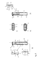
包装組立体1の特定の構造及びその様々な構成部品が相互に連結及び関係する様式について、図4及び図5の2つの分解図並びに図6(a)〜図6(k)及び図7(a)〜図7(k)を具体的に参照して説明する。図6(a)〜図6(k)及び図7(a)〜図7(k)は、包装組立体1の複数の断面図を示すだけでなく、種々の操作状態における包装組立体1の特定の特徴についての詳細もまた示している。
The specific structure of the
図面の図4及び図5から明らかなように、包装組立体1のヒンジ連結部8は、カバー部材又は蓋7上のヒンジ要素9を含み、ヒンジ要素9は、外側筐体5の後側の相補的なヒンジ要素10の間に受容されて、該相補的なヒンジ要素10と協同する。対応するピン11は、それぞれのヒンジ要素9,10内に挿入されて、このヒンジ連結部8のための外側枢軸Oを画定する。加えて、内側筐体2は、直立した棒状の連結要素12であって、対応するスタッドピン14の一方の端部を受容するための横向溝13を上側端部に含んでいる連結要素12を有することがわかる。各スタッドピン14の反対側の端は、カバー部材又は蓋7の内側に設けられた追加のヒンジ要素15の対応する孔に挿入されている。このようにして、蓋7は、ヒンジ連結部8を介し外側枢軸Oを中心として外側筐体5に枢支連結されるだけでなく、連結要素12の上端において第2ヒンジ連結部16を介し内側枢軸Xを中心として内側筐体2にも枢支連結されている。この二重ヒンジ連結部は、図7(b)及び図7(h)に示される断面図において最も明らかであろう。
As can be seen from FIGS. 4 and 5 of the drawings, the
外側筐体5及び内側筐体2の両方に対するヒンジ連結部8,16があるため、外側筐体5を内側筐体2に対して(図1に示す)第1位置Aから(図2に示す)第2位置Bへと下方に移動させることにより、蓋7が、外側筐体5の上端にてリム17を封止している閉位置から追い出される。ここで、外側筐体5が内側筐体2の直立した棒状の連結要素12に対して下方に移動し、続いて該連結要素12がカバー部材7と接触して上方に作用することにより、カバー部材7が開くことになる。これが起こると、スタッドピン14は、内側枢軸Xを中心として枢動することが可能になると共に、連結要素12の水平溝状の凹部13内で横方向に移動することも可能になり、それによって、外側筐体5とのヒンジ連結部8における外側枢軸線Oを中心として蓋7を回動させることが可能になる。この実施形態のヒンジ連結部8は、外側筐体5の後側から突出するように形成されているが、包装組立体1に平滑又は面一な後面を設けるため、代わりに外側筐体5内へ設置され得ることに留意されたい。
Since there are
図4及び図5を再び参照すると、包装組立体1は、内部区画4を画定する筒状収容体3の1つの中心周りにて、内側筐体2と外側筐体5との間に取り付けられたコイルばね18を含む。このコイルばね18は、図6に示すように、外側筐体5を第1位置Aに付勢するように構成されている。それにより、使用者が外側筐体5を把持して内側筐体2に対して第2位置Bに向かって上下方向に下降させると、外側筐体5の移動がコイルばね18の押勢力に抗して起こり、その移動によってコイルばね18が徐々に圧縮される(図6(d)及び図7(d)参照)。
Referring again to FIGS. 4 and 5, the
包装組立体1はまた、突部又は当接部の形態である止め要素19,20を含み、これらの止め要素19,20は、相互係合して内側筐体2に対する外側筐体5の移動の限界を画定しており、これによって第1及び第2位置A,Bを効果的に画定している。例えば、図6(b)及び、特に該図における上側の詳細を参照すると、外側筐体5が内側に向いた突部又は肩部19を含んでおり、該突部又は肩部19は、内側筐体2の後側部の溝又は凹部21内へと延びており、その凹部21の上端にて肩部又は相補的な当接部材20に係合して、外側筐体5がコイルばね18の付勢に抗して内側筐体2に対し上方に移動することを制限することがわかる。また、図7(b)及び該図における2つの詳細のうち対応する上側も参照すると、外側筐体の内側部にて内方へと突出している当接要素19もまた同様に、内部筐体2の後側部に形成された凹部21の肩部又は下端20’と協同して、下方止め部を形成する又は外側筐体5の第2位置Bにおける下方への変位を制限する。
The
ここで、図6(h)及び図7(h)並びに、特にこれら各図面の対応する詳細を参照すると、内側及び外側筐体2,5が相補的な掛止要素22,23を有しており、外側筐体5が内側筐体2に対して第2位置Bに向かって下方に変位した際に、相補的掛止要素22,23が互いに係合して解放可能に相互係止するように構成及び配置されていることがわかる。すなわち、相補的な係止要素22,23は、相互係止することによって、圧縮されたばね18が外側筐体5を第1位置Aに向かって付勢又は押勢するように作用していても、外側筐体5を内側筐体2に対して第2位置Bに保持すると共に、それによって蓋7を開位置に保持するよう設計されている。この点に関して、該実施形態の相補的な掛止要素22,23は、図4から特に明らかなように、内側筐体2の前側部における突起要素22と、外側筐体5の内側部における、突起要素22に隣接した相補的な鋸歯状突部23との一対を含む。図6(h)及び図7(h)に示すように、各突起部22はテーパ面又は傾斜面24及び係止面25を有し、各鋸歯状突部23も同様にテーパ面又は傾斜面26及び係止面27を有する。係止面25,27は、外側ケース5が第2位置Bにある際に、互いに係合して相互係止する。しかしながら、相補的な掛止要素22,23は、外側筐体5に対して内側筐体2の端部(例えば、端部キャップ6)に所定の力を加えることにより、互いに自動的に係合解除又は解放されるように設計されている。この目的のため、突起要素22は、相互係止及び解放の両方を容易にするよう屈曲し又は撓み得る。
Referring now to FIGS. 6 (h) and 7 (h), and particularly the corresponding details of each of these figures, the inner and
包装組立体1の外側本体部又は外側筐体5が第2位置Bに移動させられてカバー部材又は蓋7が図2及び図7に示される開位置にある際に、内側筐体2,5とカバー部材又は蓋との相互連結及びばね要素18を備えた機構は、e−シガレット又は物品Cの1つがそれぞれ1つの内部区画4内に(再)挿入又は(再)導入される際に、閉位置に戻るように蓋7を自動的に移動させるように構成されている。すなわち、内部区画4に挿入された際に、e−シガレットCの端部が内側筐体2の底部を形成するキャップ6の内側部に接触して押圧される。このようにして、使用者は、e−シガレットCを介して外側筐体5に対し内側筐体2に小さな力又は衝撃を付与することができ、そして該力又は衝撃は相補的な掛止要素22,23を係合解除又は解放するように作用し、それによって内側又は外側筐体2,5がコイルばね18の作用又は付勢によって互いに対して第1位置Aまで移動し、カバー部材又は蓋7が開位置から閉位置に戻るように移動する。使用者に保持された外側本体部5に対して内側本体部2に作用するe−シガレットCの重量であっても、掛止手段22,23を係合解除又は解放するのに十分であり得る。
When the outer main body or
最後に、外側筐体5は、包装組立体1の両側において隆起した輪郭を有するグリップ要素28であって、外側筐体5に対する使用者のグリップを向上させて使用者による外側筐体5の快適かつ安全な取り扱いを促進するためのグリップ要素28を含んでいることに留意されたい。これにより、グリップ要素28は、外側筐体5が内側筐体2に対して第1位置Aと第2位置Bとの間で手動で動くことを容易にすることができる。グリップ要素28は、外側筐体5と共に射出成形されてもよく、外側筐体5の側面に形成された凹部に挿入される又は該凹部から延びている弾性合成ゴム片を用いてもよい。
Finally, the
本明細書では、本発明の特定の実施形態について図示及び記載しているが、当業者であれば、様々な代替の及び/又は均等な実施形態が存在することを理解するであろう。1つ以上の例示の実施形態は単なる例示であって、いかなる形であれその範囲、適用可能性又は構成を限定することを意図するものではないことを理解されたい。むしろ、前述の要約及び詳細な説明は、当業者に対して少なくとも1つの例示の実施形態を実施するための便宜的な道筋を提供するが、例示の実施形態に記載された機能及び構成において、様々な変更が添付の特許請求の範囲に記載された範囲及びそれらの法的な均等物から逸脱することなく行われ得る。概して、この出願は、本明細書で説明した特定の実施形態についての任意の適合又は変形を包含することを意図している。 Although specific embodiments of the present invention are illustrated and described herein, those skilled in the art will appreciate that various alternative and / or equivalent embodiments exist. It should be understood that the exemplary embodiment or exemplary embodiments are only examples, and are not intended to limit the scope, applicability, or configuration in any way. Rather, the foregoing summary and detailed description provide those skilled in the art with a convenient path to implement at least one exemplary embodiment, but in the functions and configurations described in the exemplary embodiment, Various changes may be made without departing from the scope of the appended claims and their legal equivalents. In general, this application is intended to cover any adaptations or variations on the specific embodiments described herein.
また、本明細書において、「備える("comprise"、"comprising")」、「含む("include"、"including")」、「包含する("contain"、"containing")」、「有する("have"、"having")」及びそれらの任意の変形は、包括的(すなわち、非排他的)な意味で理解されることが意図されており、本明細書に記載されたプロセス、方法、機器、装置又はシステムは、詳述されたそれらの特徴、部分、要素又はステップに限定されるものではなく、明示的に記載されていない又はそのようなプロセス、方法、物品若しくは装置に固有のものではない他の要素、特徴、部分又はステップを含んでいてもよい。さらに、本明細書で使用されている用語"a"及び"an"は、他に明示的に述べられていない限り、1つ又は複数を意味すると理解されることを意図している。さらに、用語「第1」、「第2」、「第3」等は、単に標識として使用され、数的な要件を課すること及びそれらの対象の重要性についての特定の順位を確立することを意図したものではない。 Further, in this specification, “comprising” (“comprise”, “comprising”) ”,“ including ”(“ include ”,“ including ”)”, “including” (“contain”, “containing”) ”,“ having ( “have”, “having”) and any variations thereof are intended to be understood in a comprehensive (ie, non-exclusive) sense, and the processes, methods, Equipment, devices, or systems are not limited to those detailed features, parts, elements, or steps, and are not explicitly described or unique to such processes, methods, articles, or devices It may include other elements, features, parts or steps that are not. Further, as used herein, the terms “a” and “an” are intended to be understood to mean one or more, unless explicitly stated otherwise. In addition, the terms “first”, “second”, “third”, etc. are used merely as indicators to impose numerical requirements and establish a specific rank for the importance of their objects. Is not intended.
1 包装組立体
2 内側本体部又は内側筐体
3 筒状収容体
4 内部区画
5 外側本体部又は外側筐体
6 端部キャップ
7 カバー部材又は蓋
8 ヒンジ連結部
9 ヒンジ要素
10 ヒンジ要素
11 ピン
12 連結要素
13 横向溝又は横向凹部
14 スタッドピン
15 ヒンジ要素
16 ヒンジ連結部
17 外側筐体の上方リム
18 ばね要素
19 止め要素又は突部
20 止め要素又は肩部
21 溝又は凹部
22 掛止要素又は突起要素
23 掛止要素又は鋸歯状突部
24 テーパ面又は傾斜面
25 係止面
26 テーパ面又は傾斜面
27 係止面
28 グリップ要素
30 締結クリップ
31 舌状要素
32 溝
C 物品又はe−シガレット
A 第1位置
B 第2位置
d 変位距離
O 外側枢軸
X 内側枢軸
DESCRIPTION OF
Claims (14)
物品(C)を受容するための少なくとも1つの内部区画(4)を画定する内側本体部(2)、
前記内側本体部(2)を少なくとも部分的に包囲する又は取り囲む外側本体部(5)、及び、
前記少なくとも1つの内部区画(4)へのアクセスを防止する閉位置と前記少なくとも1つの内部区画(4)へのアクセスを可能にする開位置との間を移動可能なカバー部材(7)を備えており、
前記外側本体部(5)は、前記閉位置と前記開位置との間でカバー部材(7)を移動させるために、前記内側本体部(2)に対して第1位置(A)と第2位置(B)との間で移動可能であり、
前記内側及び外側本体部(2,5)は、前記内側本体部(2)に対して前記外側本体部(5)が前記第2位置(B)にある際に、前記カバー部材(7)を開位置に保持するよう互いに係合して解放可能に掛止又は相互係止するよう構成及び配置された相補的な掛止手段を含んでおり、
前記カバー部材(7)は、前記外側本体部(5)の上方リム部(17)に位置する外側ヒンジ連結部(8)を介して前記外側本体部(5)に枢支連結されており、
前記カバー部材(7)は、前記カバー部材(7)が前記内側本体部(2)に対して前記開位置と前記閉位置との間で枢動するように、内側ヒンジ連結部(16)を介して前記内側本体部(2)に枢支連結されている、包装組立体(1)。 A packaging assembly (1) for packaging one or more articles (C), comprising:
An inner body (2) defining at least one internal compartment (4) for receiving an article (C);
An outer body (5) that at least partially surrounds or surrounds the inner body (2), and
A cover member (7) movable between a closed position preventing access to the at least one internal compartment (4) and an open position allowing access to the at least one internal compartment (4); And
The outer body portion (5) has a first position (A) and a second position with respect to the inner body portion (2) to move the cover member (7) between the closed position and the open position. Movable between position (B),
The inner and outer body parts (2, 5) are configured to disengage the cover member (7) when the outer body part (5) is in the second position (B) relative to the inner body part (2). Including complementary latching means constructed and arranged to releasably latch or interlock with each other to hold in an open position ;
The cover member (7) is pivotally connected to the outer body part (5) via an outer hinge connection part (8) located at an upper rim part (17) of the outer body part (5),
The cover member (7) has an inner hinge connecting part (16) so that the cover member (7) pivots between the open position and the closed position with respect to the inner body part (2). A packaging assembly (1) pivotally connected to the inner body part (2) via
前記カバー部材(7)は、その内側に設けられた追加のヒンジ要素(15)であって、前記スタッドピン(14)の他方の端部を受容するための孔を含んでいる追加のヒンジ要素(15)備えており、 The cover member (7) is an additional hinge element (15) provided on the inside of the cover member (7), which includes a hole for receiving the other end of the stud pin (14) (15)
前記内側ヒンジ連結部(16)は、前記スタッドピン(14)の一方の端部を前記連結要素(12)の前記横向溝(13)内に、他方の端部を前記追加のヒンジ要素(15)の前記孔内に挿入することによって、前記連結要素(12)と、前記追加のヒンジ要素(15)とを連結している部分である、請求項1〜3のいずれか1項に記載の包装組立体。 The inner hinge connecting portion (16) has one end of the stud pin (14) in the lateral groove (13) of the connecting element (12) and the other end of the additional hinge element (15). 4) is a portion connecting the connecting element (12) and the additional hinge element (15) by being inserted into the hole. Packaging assembly.
Applications Claiming Priority (3)
| Application Number | Priority Date | Filing Date | Title |
|---|---|---|---|
| EP14166417 | 2014-04-29 | ||
| EP14166417.7 | 2014-04-29 | ||
| PCT/EP2015/058822 WO2015165801A1 (en) | 2014-04-29 | 2015-04-23 | Packaging assembly |
Publications (2)
| Publication Number | Publication Date |
|---|---|
| JP2017520479A JP2017520479A (en) | 2017-07-27 |
| JP6313472B2 true JP6313472B2 (en) | 2018-04-18 |
Family
ID=50630626
Family Applications (1)
| Application Number | Title | Priority Date | Filing Date |
|---|---|---|---|
| JP2016565253A Active JP6313472B2 (en) | 2014-04-29 | 2015-04-23 | Packaging assembly |
Country Status (6)
| Country | Link |
|---|---|
| US (1) | US10435201B2 (en) |
| EP (1) | EP3136901B1 (en) |
| JP (1) | JP6313472B2 (en) |
| ES (1) | ES2685851T3 (en) |
| PL (1) | PL3136901T3 (en) |
| WO (1) | WO2015165801A1 (en) |
Families Citing this family (13)
| Publication number | Priority date | Publication date | Assignee | Title |
|---|---|---|---|---|
| US11395372B2 (en) * | 2016-06-13 | 2022-07-19 | Db Innovation Inc. | Vaporization device, a charging adaptor for a disposable vaporization device, and a kit |
| CN106509991B (en) * | 2016-10-18 | 2018-11-13 | 云南中烟工业有限责任公司 | A kind of slidingtype hood-opening device |
| EA039375B1 (en) | 2016-12-27 | 2022-01-20 | Джуул Лэбз, Инк. | Thermal wick for electronic vaporizers |
| ES2929474T3 (en) | 2018-07-23 | 2022-11-29 | Juul Labs Inc | Airflow management for vaporizer device |
| FR3087093A1 (en) | 2018-10-15 | 2020-04-17 | Juul Labs, Inc. | HEATING ELEMENT |
| JP6946472B2 (en) | 2018-10-19 | 2021-10-06 | ジュール・ラブズ・インコーポレイテッドJuul Labs, Inc. | Vaporizer power supply system |
| EA202190764A1 (en) * | 2018-10-25 | 2021-07-22 | ДжейТи ИНТЕРНЕШНЛ СА | DOSING DEVICE AND ADDITIONAL EVAPORATOR |
| CN109502165B (en) * | 2018-11-21 | 2023-11-07 | 中国船舶重工集团公司第七一九研究所 | Axial interlocking device for front cover and rear cover of cylinder |
| US11253001B2 (en) * | 2019-02-28 | 2022-02-22 | Juul Labs, Inc. | Vaporizer device with vaporizer cartridge |
| US11617390B2 (en) * | 2019-12-18 | 2023-04-04 | Justin Tidwell | Child resistant pre-roll case and related methods |
| US20210186093A1 (en) * | 2019-12-19 | 2021-06-24 | Armen Tovmasyan | Vaporizer Accessory Case and Kit |
| CA3123437A1 (en) | 2021-05-05 | 2022-11-05 | Richard Gene Lafler Jr. | Container for elongated or small objects |
| CN114030749A (en) * | 2021-10-14 | 2022-02-11 | 吴成亮 | Intelligent medicine consumable container for medical examination |
Family Cites Families (16)
| Publication number | Priority date | Publication date | Assignee | Title |
|---|---|---|---|---|
| US1934138A (en) * | 1933-01-03 | 1933-11-07 | Leon R Paul | Dispensing can |
| US2155613A (en) * | 1938-06-29 | 1939-04-25 | Negbaur & Co Inc H | Receptacle |
| JPS50112480U (en) | 1974-02-23 | 1975-09-12 | ||
| JPS5547131Y2 (en) | 1975-05-15 | 1980-11-05 | ||
| JPS52140985U (en) | 1976-04-19 | 1977-10-25 | ||
| JPS59118725U (en) * | 1983-01-28 | 1984-08-10 | 株式会社資生堂 | storage container |
| FR2571698B1 (en) * | 1984-10-16 | 1987-02-27 | Bourbon Fils Ets A | CASE INTENDED IN PARTICULAR FOR THE STORAGE AND THE PRESENTATION OF OBJECTS SUCH AS SHEETS, DISCS, PENCILS |
| NL8403959A (en) * | 1984-12-28 | 1986-07-16 | Cornelis Van Buuren | PACKAGING FOR COSMETIC PRODUCTS. |
| JPH0616Y2 (en) | 1989-03-20 | 1994-01-05 | 株式会社トキワ | Cosmetic container |
| US5732820A (en) * | 1996-11-25 | 1998-03-31 | Tsai; Hung Chic | Stick object storage box |
| US7128215B2 (en) * | 2004-03-23 | 2006-10-31 | Sasan Danechi | Container for cotton swabs |
| US7320397B2 (en) | 2004-06-07 | 2008-01-22 | Contour Optik, Inc. | Eyeglasses case |
| US7484620B2 (en) * | 2005-11-14 | 2009-02-03 | Black & Decker Inc. | Accessory storage case |
| US20080179323A1 (en) * | 2007-01-25 | 2008-07-31 | Helen Of Troy Limited | Closable container for personal items |
| WO2013103664A1 (en) * | 2012-01-03 | 2013-07-11 | Csp Technologies, Inc. | Dispenser |
| US20130248385A1 (en) | 2012-03-23 | 2013-09-26 | Njoy, Inc. | Electronic cigarette container |
-
2015
- 2015-04-23 EP EP15720304.3A patent/EP3136901B1/en active Active
- 2015-04-23 WO PCT/EP2015/058822 patent/WO2015165801A1/en active Application Filing
- 2015-04-23 PL PL15720304T patent/PL3136901T3/en unknown
- 2015-04-23 US US15/307,278 patent/US10435201B2/en active Active
- 2015-04-23 JP JP2016565253A patent/JP6313472B2/en active Active
- 2015-04-23 ES ES15720304.3T patent/ES2685851T3/en active Active
Also Published As
| Publication number | Publication date |
|---|---|
| US20170043910A1 (en) | 2017-02-16 |
| US10435201B2 (en) | 2019-10-08 |
| PL3136901T3 (en) | 2019-01-31 |
| WO2015165801A1 (en) | 2015-11-05 |
| JP2017520479A (en) | 2017-07-27 |
| ES2685851T3 (en) | 2018-10-11 |
| EP3136901A1 (en) | 2017-03-08 |
| EP3136901B1 (en) | 2018-06-06 |
Similar Documents
| Publication | Publication Date | Title |
|---|---|---|
| JP6313472B2 (en) | Packaging assembly | |
| JP6831751B2 (en) | Travel bag with extended functions | |
| US20200198854A1 (en) | Child-resistant smoking article package | |
| US10420703B1 (en) | Pill container | |
| JP6465866B2 (en) | Container with button release means | |
| US8091709B2 (en) | Child-resistant package | |
| US8657136B2 (en) | Child resistant bulk dose dispensing unit | |
| JP5642711B2 (en) | Child resistant container | |
| GB2540100A (en) | Latchable package | |
| JP2010524787A (en) | Function restriction clip for containers with lock | |
| JP2010536667A (en) | Container with lock function | |
| JP6210960B2 (en) | Household thin paper storage container | |
| JP2005510224A (en) | Container for cigarette packaging box or cigarillo box | |
| JP6000547B2 (en) | Slidable container with child lock | |
| JP5956338B2 (en) | package | |
| US11542073B2 (en) | Childproof container closure | |
| WO2015165906A1 (en) | Packaging assembly | |
| JP6031982B2 (en) | Container with button | |
| JP2014133567A (en) | Cover case with spring | |
| CN209871178U (en) | Container with child-resistant closure | |
| JP7138978B2 (en) | Beverage container stopper and thermos bottle equipped with the same | |
| WO2007016249A2 (en) | Multi-day or ergonomic dispensers for small objects | |
| JP6830643B2 (en) | Storage case | |
| KR20140100014A (en) | Products Case for Checking Whether it is opend or not | |
| CN111017396A (en) | Packaging piece |
Legal Events
| Date | Code | Title | Description |
|---|---|---|---|
| A131 | Notification of reasons for refusal |
Free format text: JAPANESE INTERMEDIATE CODE: A131 Effective date: 20170901 |
|
| A601 | Written request for extension of time |
Free format text: JAPANESE INTERMEDIATE CODE: A601 Effective date: 20171201 |
|
| A521 | Request for written amendment filed |
Free format text: JAPANESE INTERMEDIATE CODE: A523 Effective date: 20180131 |
|
| TRDD | Decision of grant or rejection written | ||
| A01 | Written decision to grant a patent or to grant a registration (utility model) |
Free format text: JAPANESE INTERMEDIATE CODE: A01 Effective date: 20180223 |
|
| A61 | First payment of annual fees (during grant procedure) |
Free format text: JAPANESE INTERMEDIATE CODE: A61 Effective date: 20180322 |
|
| R150 | Certificate of patent or registration of utility model |
Ref document number: 6313472 Country of ref document: JP Free format text: JAPANESE INTERMEDIATE CODE: R150 |
|
| R250 | Receipt of annual fees |
Free format text: JAPANESE INTERMEDIATE CODE: R250 |
|
| R250 | Receipt of annual fees |
Free format text: JAPANESE INTERMEDIATE CODE: R250 |
|
| R250 | Receipt of annual fees |
Free format text: JAPANESE INTERMEDIATE CODE: R250 |