JP6210960B2 - Household thin paper storage container - Google Patents
Household thin paper storage container Download PDFInfo
- Publication number
- JP6210960B2 JP6210960B2 JP2014201106A JP2014201106A JP6210960B2 JP 6210960 B2 JP6210960 B2 JP 6210960B2 JP 2014201106 A JP2014201106 A JP 2014201106A JP 2014201106 A JP2014201106 A JP 2014201106A JP 6210960 B2 JP6210960 B2 JP 6210960B2
- Authority
- JP
- Japan
- Prior art keywords
- thin paper
- household thin
- upper lid
- lid
- outlet
- Prior art date
- Legal status (The legal status is an assumption and is not a legal conclusion. Google has not performed a legal analysis and makes no representation as to the accuracy of the status listed.)
- Active
Links
Images


Classifications
-
- B—PERFORMING OPERATIONS; TRANSPORTING
- B65—CONVEYING; PACKING; STORING; HANDLING THIN OR FILAMENTARY MATERIAL
- B65D—CONTAINERS FOR STORAGE OR TRANSPORT OF ARTICLES OR MATERIALS, e.g. BAGS, BARRELS, BOTTLES, BOXES, CANS, CARTONS, CRATES, DRUMS, JARS, TANKS, HOPPERS, FORWARDING CONTAINERS; ACCESSORIES, CLOSURES, OR FITTINGS THEREFOR; PACKAGING ELEMENTS; PACKAGES
- B65D83/00—Containers or packages with special means for dispensing contents
- B65D83/08—Containers or packages with special means for dispensing contents for dispensing thin flat articles in succession
- B65D83/0805—Containers or packages with special means for dispensing contents for dispensing thin flat articles in succession through an aperture in a wall
- B65D83/0811—Containers or packages with special means for dispensing contents for dispensing thin flat articles in succession through an aperture in a wall with means for assisting dispensing
- B65D83/0835—Containers or packages with special means for dispensing contents for dispensing thin flat articles in succession through an aperture in a wall with means for assisting dispensing the articles being pulled out of the container
-
- A—HUMAN NECESSITIES
- A47—FURNITURE; DOMESTIC ARTICLES OR APPLIANCES; COFFEE MILLS; SPICE MILLS; SUCTION CLEANERS IN GENERAL
- A47K—SANITARY EQUIPMENT NOT OTHERWISE PROVIDED FOR; TOILET ACCESSORIES
- A47K10/00—Body-drying implements; Toilet paper; Holders therefor
- A47K10/24—Towel dispensers, e.g. for piled-up or folded textile towels; Toilet-paper dispensers; Dispensers for piled-up or folded textile towels provided or not with devices for taking-up soiled towels as far as not mechanically driven
- A47K10/32—Dispensers for paper towels or toilet-paper
- A47K10/42—Dispensers for paper towels or toilet-paper dispensing from a store of single sheets, e.g. stacked
- A47K10/421—Dispensers for paper towels or toilet-paper dispensing from a store of single sheets, e.g. stacked dispensing from the top of the dispenser
-
- A—HUMAN NECESSITIES
- A47—FURNITURE; DOMESTIC ARTICLES OR APPLIANCES; COFFEE MILLS; SPICE MILLS; SUCTION CLEANERS IN GENERAL
- A47K—SANITARY EQUIPMENT NOT OTHERWISE PROVIDED FOR; TOILET ACCESSORIES
- A47K10/00—Body-drying implements; Toilet paper; Holders therefor
- A47K10/16—Paper towels; Toilet paper; Holders therefor
- A47K10/18—Holders; Receptacles
- A47K10/20—Holders; Receptacles for piled sheets
-
- A—HUMAN NECESSITIES
- A47—FURNITURE; DOMESTIC ARTICLES OR APPLIANCES; COFFEE MILLS; SPICE MILLS; SUCTION CLEANERS IN GENERAL
- A47K—SANITARY EQUIPMENT NOT OTHERWISE PROVIDED FOR; TOILET ACCESSORIES
- A47K10/00—Body-drying implements; Toilet paper; Holders therefor
- A47K10/24—Towel dispensers, e.g. for piled-up or folded textile towels; Toilet-paper dispensers; Dispensers for piled-up or folded textile towels provided or not with devices for taking-up soiled towels as far as not mechanically driven
- A47K10/32—Dispensers for paper towels or toilet-paper
- A47K10/42—Dispensers for paper towels or toilet-paper dispensing from a store of single sheets, e.g. stacked
-
- B—PERFORMING OPERATIONS; TRANSPORTING
- B65—CONVEYING; PACKING; STORING; HANDLING THIN OR FILAMENTARY MATERIAL
- B65D—CONTAINERS FOR STORAGE OR TRANSPORT OF ARTICLES OR MATERIALS, e.g. BAGS, BARRELS, BOTTLES, BOXES, CANS, CARTONS, CRATES, DRUMS, JARS, TANKS, HOPPERS, FORWARDING CONTAINERS; ACCESSORIES, CLOSURES, OR FITTINGS THEREFOR; PACKAGING ELEMENTS; PACKAGES
- B65D83/00—Containers or packages with special means for dispensing contents
- B65D83/08—Containers or packages with special means for dispensing contents for dispensing thin flat articles in succession
- B65D83/0894—Containers or packages with special means for dispensing contents for dispensing thin flat articles in succession the articles being positioned relative to one another or to the container in a special way, e.g. for facilitating dispensing, without additional support
-
- A—HUMAN NECESSITIES
- A47—FURNITURE; DOMESTIC ARTICLES OR APPLIANCES; COFFEE MILLS; SPICE MILLS; SUCTION CLEANERS IN GENERAL
- A47K—SANITARY EQUIPMENT NOT OTHERWISE PROVIDED FOR; TOILET ACCESSORIES
- A47K10/00—Body-drying implements; Toilet paper; Holders therefor
- A47K10/24—Towel dispensers, e.g. for piled-up or folded textile towels; Toilet-paper dispensers; Dispensers for piled-up or folded textile towels provided or not with devices for taking-up soiled towels as far as not mechanically driven
- A47K10/32—Dispensers for paper towels or toilet-paper
- A47K2010/3266—Wet wipes
Landscapes
- Health & Medical Sciences (AREA)
- Public Health (AREA)
- Engineering & Computer Science (AREA)
- Mechanical Engineering (AREA)
- Containers And Packaging Bodies Having A Special Means To Remove Contents (AREA)
- Closures For Containers (AREA)
Description
本発明は、家庭用薄葉紙を収納する家庭用薄葉紙収納容器に関する。 The present invention relates to a household thin paper storage container for storing household thin paper.
従来、家屋の床やトイレ、或いは人体などを拭くための家庭用薄葉紙を収納する家庭用薄葉紙収納容器が知られている。
このような家庭用薄葉紙収納容器においては、家庭用薄葉紙を収納するためのケース体の上面に、その開放端を上下方向に回動させることで開閉を行う蓋体を設けた構成が一般的である。しかしながら、この構成の場合、蓋体を開くと当該蓋体が起立した状態になるため、蓋体を開ける際に高さが必要となり、狭いスペースでは使いづらいという問題があった。また、この構成の場合、蓋体を開くと当該蓋体が起立した状態になるため、蓋体が邪魔になって蓋体の後ろ側からは家庭用薄葉紙が取り出しづらいという問題があった。
これに対し、スライド移動することで開閉を行う蓋体を設けた構成(例えば、特許文献1参照)とすれば、蓋体が開いても蓋体が起立した状態にならないため、狭いスペースでも使いやすく、蓋体が邪魔にならず家庭用薄葉紙を全方向から取り出すことができる。
上記の家庭用薄葉紙収納容器においては、家庭用薄葉紙の取出口の周縁部に、枠部材が装着されており、この枠部材に家庭用薄葉紙を下方から上方に通すことで家庭用薄葉紙を取り出すことができるようになっている。
2. Description of the Related Art Conventionally, household thin paper storage containers for storing household thin paper for wiping the floor, toilet, or human body of a house are known.
In such a household thin paper storage container, a configuration in which a cover body that opens and closes by rotating the open end in the vertical direction on the upper surface of a case body for storing household thin paper is generally used. is there. However, in this configuration, when the lid is opened, the lid is in an upright state, so that the height is required when opening the lid, and there is a problem that it is difficult to use in a narrow space. Further, in the case of this configuration, when the lid is opened, the lid is in an upright state, so that there is a problem that it is difficult to take out household thin paper from the rear side of the lid due to the lid.
On the other hand, if a configuration is provided in which a lid that opens and closes by sliding is provided (see, for example, Patent Document 1), the lid does not stand up even when the lid is opened. It is easy to take out the household thin paper from all directions without obstructing the lid.
In the above-mentioned household thin paper storage container, a frame member is attached to the peripheral portion of the outlet of the household thin paper, and the household thin paper is taken out by passing the household thin paper from above to below the frame member. Can be done.
しかしながら、特許文献1記載の構成の場合、枠部材が取出口の周縁部を覆うものであるため、枠部材の開口部分の面積が広く、家庭用薄葉紙を取り出した際に、次の家庭用薄葉紙が飛び出し過ぎて、上蓋20を閉める際に当該家庭用薄葉紙を噛み込んでしまうという問題がある。
枠部材の開口部分の面積を狭くする方法も考えられるが、その場合、枠部材の下方に落ち込んだ家庭用薄葉紙を摘まんで取り出すことが困難になるという問題がある。
However, in the case of the configuration described in
Although the method of narrowing the area of the opening part of a frame member is also considered, in that case, there exists a problem that it becomes difficult to pinch and take out the household thin paper which fell below the frame member.
本発明の課題は、枠部材の下方に落ち込んだ家庭用薄葉紙の取り出しを阻害することなく、家庭用薄葉紙の飛び出し量を抑制可能な家庭用薄葉紙収納容器を提供することである。 The subject of this invention is providing the household thin paper storage container which can suppress the pop-out amount of household thin paper, without inhibiting taking-out of the household thin paper which fell below the frame member.
上記課題を解決するために、請求項1に記載の発明は、
上面に取出口を有し、内側に家庭用薄葉紙を収納するケース体と、
前記取出口を開閉させる蓋体と、を備える家庭用薄葉紙収納容器において、
前記取出口の周縁部に装着された枠部材を備え、
前記枠部材は、弾性部材により形成され、
前記枠部材の前記ケース体の平面視短手方向の各端部には、前記取出口を塞ぐ方向に延出する抑え部が設けられ、
前記抑え部のそれぞれは、互いに重ならないようにその先端の前記ケース体の平面視長手方向の位相をずらして配置され、前記枠部材にZ字状の切込みが形成され、
前記枠部材は、硬度が90°のエラストマー樹脂により形成されていることを特徴とする。
In order to solve the above-mentioned problem, the invention described in
A case body having an outlet on the top surface and storing household thin paper on the inside;
In a household thin paper storage container comprising a lid that opens and closes the outlet,
A frame member mounted on the peripheral edge of the outlet;
The frame member is formed of an elastic member,
Each end portion of the frame member in the short side direction of the case body in the plan view is provided with a holding portion that extends in a direction to close the outlet,
Each of the holding portions is arranged with a phase shift in the longitudinal direction of the case body at the tip thereof so as not to overlap each other, and a Z-shaped cut is formed in the frame member,
The frame member is formed of an elastomer resin having a hardness of 90 ° .
請求項2に記載の発明は、請求項1に記載の家庭用薄葉紙収納容器において、
前記取出口は、平面視にて前記蓋体の開放状態時における当該家庭用薄葉紙収納容器自体の重心からずれた位置に設けられ、
前記枠部材の前記重心側には、前記抑え部と重ならないように前記取出口を塞ぐ方向に延出する延出部が設けられていることを特徴とする。
The invention according to claim 2 is the household thin paper storage container according to
The outlet is provided at a position deviated from the center of gravity of the household thin paper storage container itself when the lid is opened in plan view.
An extension portion that extends in a direction to close the outlet is provided on the gravity center side of the frame member so as not to overlap the holding portion.
請求項3に記載の発明は、請求項1又は2に記載の家庭用薄葉紙収納容器において、
前記家庭用薄葉紙は、折り畳まれて前記ケース体に収納され、
前記家庭用薄葉紙の折り方向は、前記ケース体の平面視長手方向に対して平行であることを特徴とする。
The invention according to claim 3 is the thin paper storage container for home use according to
The household thin paper is folded and stored in the case body,
The folding direction of the household thin paper is parallel to the longitudinal direction of the case body in plan view.
請求項4に記載の発明は、請求項1〜3のいずれか一項に記載の家庭用薄葉紙収納容器において、
前記蓋体は、前記ケース体に対してスライド移動することで前記取出口を開閉させることを特徴とする。
Invention of Claim 4 is a household thin paper storage container as described in any one of Claims 1-3 ,
The lid body is configured to open and close the outlet by sliding movement with respect to the case body.
本発明によれば、枠部材の下方に落ち込んだ家庭用薄葉紙の取り出しを阻害することなく、家庭用薄葉紙の飛び出し量を抑制することができる。 ADVANTAGE OF THE INVENTION According to this invention, the pop-out amount of household thin paper can be suppressed, without inhibiting taking out of household thin paper which fell below the frame member.
以下、本発明の実施の形態を図面に基づいて説明する。ただし、発明の範囲は、図示例に限定されない。 Hereinafter, embodiments of the present invention will be described with reference to the drawings. However, the scope of the invention is not limited to the illustrated examples.
<家庭用薄葉紙収納容器の構成>
まず、本実施形態の家庭用薄葉紙収納容器の構成について説明する。
なお、以下の説明では、家庭用薄葉紙収納容器の平面視長手方向を左右方向、平面視短手方向を前後方向、高さ方向を上下方向とする。
<Composition of household thin paper storage container>
First, the structure of the household thin paper storage container of this embodiment is demonstrated.
In the following description, the longitudinal direction of the household thin paper storage container is the left-right direction, the short side direction of the planar view is the front-rear direction, and the height direction is the vertical direction.
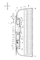
本実施形態に係る家庭用薄葉紙収納容器1は、例えば、図1(a)に示すように、上蓋20を閉じた状態で前後方向の側面視にて上側の角が丸みを帯びた略長方形状に形成されており、内部にウェットシートやウェットティシュー等のウェットタイプの家庭用薄葉紙Pを収納可能に構成されている。なお、家庭用薄葉紙収納容器1には、ティシューペーパーやキッチンペーパーやペーパータオル等のドライタイプの家庭用薄葉紙Pを収納しても良い。
具体的には、家庭用薄葉紙収納容器1は、例えば、図1〜図5に示すように、上面に家庭用薄葉紙Pを取り出すための取出口11を有するとともに下面に家庭用薄葉紙Pが積層された薄葉紙積層体Qを詰め替えるための底面開口12を有し、内側の収納空間部Sに薄葉紙積層体Qを収納する容器本体10と、容器本体10の上面にスライド移動自在に設けられ、取出口11を開閉させる蓋体としての上蓋20と、上蓋20を容器本体10に取り付けるためのシャーシ30と、容器本体10の底面開口12を塞ぐ底蓋40と、上蓋20を開放状態となる方向に付勢する付勢部材50と、等を備えて構成される。
As shown in FIG. 1A, for example, the household thin
Specifically, for example, as shown in FIGS. 1 to 5, the household thin
容器本体10及びシャーシ30が、上面に取出口11を有し、内側に家庭用薄葉紙Pを収納するケース体として機能する。すなわち、ケース体は、容器本体10と、当該容器本体10の上面に固定されるシャーシ30と、を備えており、上蓋20は、ケース体のうちシャーシ30に取り付けられている。
また、容器本体10、上蓋20、シャーシ30及び底蓋40は、例えば、PP(ポリプロピレン)、PE(ポリエチレン)、PVC(ポリ塩化ビニル)、PET(ポリエチレンテレフタレート)、ABS(Acrylonitrile Butadiene Styrene)等の熱可塑性樹脂から形成されている。
The container
The
また、本実施形態においては、付勢部材50として、引張コイルばね(引きばね)を用いるが、これに限ることはなく、付勢部材50は、伸縮部材であれば適宜任意に変更可能であり、例えば、トーションばねや圧縮コイルばね(押しばね)等であっても良い。
また、付勢部材50は、金属材料からなる伸縮部材であっても、高分子材料からなる伸縮部材であっても良い。高分子材料からなる伸縮部材としては、例えば、プラスチック製の伸縮部材、シリコンゴム等のゴムや、スチレン系、オレフィン系、塩化ビニル系、ポリエステル系、ポリウレタン系、ナイロン系のエラストマー等の熱可塑性エラストマーなどの弾性体(軟質材料)製の伸縮部材等が挙げられ、また、その形状は、ばね状であっても、板状やチューブ状や紐状であっても良く、適宜任意に変更可能である。付勢部材50が高分子材料からなる場合、金属製の付勢部材と違って錆びることがないので、長期に亘って安定的に使用することができる。家庭用薄葉紙収納容器1に収納する家庭用薄葉紙Pが、ウェットタイプの家庭用薄葉紙Pである場合は特に、金属製の付勢部材50を用いると、家庭用薄葉紙Pから蒸発した薬液によって付勢部材が錆びる可能性が高くなるので、高分子材料からなる付勢部材50を用いることが好ましい。
In the present embodiment, a tension coil spring (pull spring) is used as the
Further, the
ここで、上蓋20は、左右方向(容器本体10の平面視長手方向)にスライド移動することで開閉を行う。すなわち、上蓋20は、閉塞状態時の位置から左右方向の一方(本実施形態の場合、左方向)にスライド移動することで開放状態となり、開放状態時の位置から左右方向の他方(本実施形態の場合、右方向)にスライド移動することで閉塞状態となる。そして、上蓋20が開放状態となる方向(左方向)に移動することで、家庭用薄葉紙収納容器1の左右一側(本実施形態の場合、左側)が、家庭用薄葉紙収納容器1の左右他側(本実施形態の場合、右側)よりも重くなるように構成されている。また、取出口11は、平面視にて上蓋20の開放状態時における家庭用薄葉紙収納容器1自体の重心からずれた位置(本実施形態の場合、右側にずれた位置)に設けられている。
以下、上蓋20の開放状態時における家庭用薄葉紙収納容器1自体の重心を、「開放重心」という。
Here, the
Hereinafter, the center of gravity of the household thin
また、薄葉紙積層体Qは、例えば、複数枚の家庭用薄葉紙Pが積層された詰替え用の薄葉紙積層体であって、ケース体(本実施形態の場合、容器本体10)に形成された取出口11から家庭用薄葉紙Pを継続して取り出せるように交互に折り重ねられた状態で積層されている。すなわち、家庭用薄葉紙Pを取出口11からケース体の外側へ引き出したときに、次の家庭用薄葉紙Pの上端が取出口11よりも突出する位置まで収納空間部Sから引き出される、いわゆるポップアップ方式となっている。
なお、薄葉紙積層体Qは、本実施形態のように家庭用薄葉紙Pを取り出すための開口T1が設けられた包装体Tによって内包されていても良いし、包装体Tによって内包されていなくても良い。特に、家庭用薄葉紙収納容器1に収納する家庭用薄葉紙Pが、本実施形態のようにウェットタイプの家庭用薄葉紙Pである場合には、薄葉紙積層体Qを防湿性の包装体Tによって内包することが好ましい。
Further, the thin paper laminate Q is, for example, a refill thin paper laminate in which a plurality of household thin papers P are laminated, and is formed on the case body (the
The thin paper laminate Q may be included in the package T provided with an opening T1 for taking out the household thin paper P as in the present embodiment, or may not be included in the package T. good. In particular, when the household thin paper P stored in the household thin
容器本体10は、例えば、図1(a)及び図1(b)に示すように、当該容器本体10の上面を構成する上面部10aと、当該容器本体10の前後左右の周面を構成する周面部10bと、からなり、容器本体10の下面は平面視にて角のとれた略長方形状を呈する底面開口12となっている。そして、この底面開口12を塞ぐように取り付けられた底蓋40と、容器本体10の上面部10a及び周面部10bと、によって囲まれた空間が、薄葉紙積層体Qを収納するための収納空間部Sとなる。
なお、本実施形態では、下面が開口した容器本体10を用い、薄葉紙積層体Qを容器本体10の下面側から詰め替えるように構成したが、これに限ることはなく、例えば、下面は閉口して前後左右の何れかの面が開口した容器本体10を用い、薄葉紙積層体Qを容器本体10の前後左右の何れかの面側から詰め替えるように構成することも可能である。
For example, as illustrated in FIGS. 1A and 1B, the
In the present embodiment, the
容器本体10の上面部10aには、例えば、図4及び図5に示すように、下側に向けて陥没する凹部13が設けられており、この凹部13の底面部13aに取出口11が形成されている。
取出口11は、容器本体10の内部の収納空間部Sに収納された家庭用薄葉紙Pを取り出すための、平面視にて角のとれた略長方形状に形成された開口である。
取出口11は、上蓋20が開放状態(図1(b)、図3、図5参照)となった場合に開放され、このとき家庭用薄葉紙Pは、取出口11を通じて一枚毎に収納空間部Sから外部に引き出すことができるようになっている。
また、取出口11は、上蓋20が閉塞状態(図1(a)、図2、図4参照)となった場合に閉塞されるようになっている。
For example, as shown in FIGS. 4 and 5, the
The take-out
The take-out
Further, the
例えば、図4及び図5に示すように、取出口11の周縁には、ケース側パッキン14が装着されている。すなわち、ケース側パッキン14が、取出口11の周縁部に装着された枠部材として機能する。
また、上蓋20の下面にも、蓋側パッキン21が取り付けられている。
蓋側パッキン21は、上蓋20の下面のうち上蓋20の閉塞状態においてケース側パッキン14に対応する位置に設けられており、ケース側パッキン14と蓋側パッキン21とは、上蓋20が閉塞状態となった場合に互いに密着して(図4参照)、収納空間部S内の気密性を保持するように構成されている。すなわち、ケース側パッキン14及び蓋側パッキン21が、取出口11の周縁と上蓋20との隙間を封止する気密手段として機能する。
これにより、家庭用薄葉紙収納容器1に収納する家庭用薄葉紙Pが、本実施形態のようにウェットタイプの家庭用薄葉紙Pである場合には、家庭用薄葉紙Pに含浸した薬液の蒸発を防止できるようになっている。
For example, as shown in FIGS. 4 and 5, a case-
A lid side packing 21 is also attached to the lower surface of the
The lid-
Thereby, when the household thin paper P stored in the household thin
本実施形態では、ケース側パッキン14及び蓋側パッキン21を、例えば、シリコンゴム等のゴムや、スチレン系、オレフィン系、塩化ビニル系、ポリエステル系、ポリウレタン系、ナイロン系のエラストマー等の熱可塑性エラストマーなどの軟質材料(弾性部材)で形成している。なお、蓋側パッキン21を形成する材料に関しては、これに限ることはない。蓋側パッキン21は、例えば、LDPE(Low Density Polyethylene)で形成しても良いし、PE(Polyethylene)やPP(Polypropylene)などの硬質材料で形成しても良い。また、蓋側パッキン21を、ケース側パッキン14と同じ材料で形成しても良いし、異なる材料で形成しても良い。また、ケース側パッキン14及び蓋側パッキン21は、家庭用薄葉紙収納容器1に収納する家庭用薄葉紙Pがウェットタイプである場合は特に、薬液耐性のある材料で形成されることが好ましい。
また、本実施形態では、容器本体10にケース側パッキン14を設けて上蓋20に蓋側パッキン21を設けた、すなわち、容器本体10と上蓋20との双方に気密手段を設けたが、これに限ることはなく、気密手段によって取出口11の周縁と上蓋20との隙間を封止できるのであれば、例えば、容器本体10だけに気密手段を設けても良い。また、シャーシ30に取出口11が設けられている場合には、シャーシ30に気密手段を設けても良い。
In this embodiment, the case side packing 14 and the lid side packing 21 are made of thermoplastic elastomer such as rubber such as silicone rubber, styrene, olefin, vinyl chloride, polyester, polyurethane, nylon, and the like. It is made of a soft material (elastic member). The material for forming the lid side packing 21 is not limited to this. The lid side packing 21 may be formed of, for example, LDPE (Low Density Polyethylene) or a hard material such as PE (Polyethylene) or PP (Polypropylene). Further, the lid side packing 21 may be formed of the same material as the case side packing 14 or may be formed of a different material. The case-
Further, in the present embodiment, the case body packing 14 is provided on the
ここで、本実施形態の場合、収納空間部Sに収納されている家庭用薄葉紙Pの折り方向、すなわち折り畳み線が延びる方向は、左右方向(容器本体10の平面視長手方向)に対して平行になっている。
また、取出口11の長手方向は、左右方向(容器本体10の平面視長手方向)に対して直交している。
したがって、家庭用薄葉紙Pは、取出口11から引き出される際に、取出口11に装着されたケース側パッキン14の短手部分(ケース側パッキン14のうち収納空間部Sに収納されている家庭用薄葉紙Pの折り方向に平行な部分)よりも、ケース側パッキン14の長手部分(ケース側パッキン14のうち収納空間部Sに収納されている家庭用薄葉紙Pの折り方向に直交する部分)に接触する。
Here, in the case of this embodiment, the folding direction of the household thin paper P stored in the storage space S, that is, the direction in which the folding line extends is parallel to the left-right direction (the longitudinal direction of the
The longitudinal direction of the
Accordingly, when the household thin paper P is pulled out from the
ケース側パッキン14の下端部は、例えば、図4及び図5に示すように、取出口11よりも下側(収納空間部Sに収納されている薄葉紙積層体Q側)に向けて突出している。したがって、最上層の家庭用薄葉紙Pを取り出す際に、ケース側パッキン14の下端部が最上層の家庭用薄葉紙Pや次層の家庭用薄葉紙Pと接触して、最上層の家庭用薄葉紙Pや次層の家庭用薄葉紙Pに抵抗を付与するので、次層の家庭用薄葉紙Pの飛び出し長さ(取出口11から突出した部分の長さ)が必要以上に長くなったり、複数枚の家庭用薄葉紙Pが連なって引き出されたりすることを抑制することができる。すなわち、家庭用薄葉紙Pが不要に飛び出さないように、ケース側パッキン14で家庭用薄葉紙Pを押さえることができる。
For example, as shown in FIGS. 4 and 5, the lower end portion of the case side packing 14 protrudes toward the lower side (the thin paper laminate Q side stored in the storage space S) than the
さらに、ケース側パッキン14の下端部のうち左側部分(開放重心側の部分)には、例えば、図6(a)及び図6(b)に示すように、内側に向けて(すなわち、取出口11を塞ぐ方向側に向けて)円弧状に延出する延出部14aが設けられている。
また、ケース側パッキン14の下端部のうち前後方向の各端部には、例えば、図6(a)及び図6(b)に示すように、取出口11を塞ぐ方向(前後方向)に延出する抑え部14bがそれぞれ設けられている。即ち、ケース側パッキン14の下端部には、切込みC1〜C4が形成され、一対の抑え部14b、14bがそれぞれ左右方向の各端部から概ね離間した状態となっている。また、抑え部14b、14bのそれぞれは、互いに重ならないようにその先端の左右方向の位相をずらして配置されている。
上記のように、一対の抑え部14b、14bを備えたことで、ケース側パッキン14にZ字状の切込みが形成されている。なお、Z字状には、「Z」の字を左右に反転させた逆Z字状のものも含むものとする。
そして、延出部14aと一対の抑え部14b、14bにより形成された把持部P1〜P3で、家庭用薄葉紙Pが把持されるようになっているため、家庭用薄葉紙Pを取り出す際、家庭用薄葉紙Pが過度に飛び出さないようになっている。
また、ケース側パッキン14及び蓋側パッキン21の少なくとも一方には、スリップ剤が添加されている。ケース側パッキン14及び蓋側パッキン21の少なくとも一方にスリップ剤を添加したことにより、上蓋20を円滑にスライド移動させることができるようになっている。
Further, the left side portion (the portion on the open center of gravity side) of the lower end portion of the case side packing 14 is directed inward (that is, as shown in FIG. 6 (a) and FIG. 6 (b)). An extending
Further, each end portion in the front-rear direction of the lower end portion of the case-
As described above, a Z-shaped cut is formed in the case side packing 14 by providing the pair of holding
Since the household thin paper P is gripped by the gripping portions P1 to P3 formed by the extending
Further, a slip agent is added to at least one of the case side packing 14 and the lid side packing 21. By adding a slip agent to at least one of the case side packing 14 and the lid side packing 21, the
また、本実施形態の場合、例えば、図7に示すように、取出口11は、平面視にて包装体Tの開口T1とずれているとともに、取出口11の中心は、平面視にて包装体Tの開口T1の中心よりも右側(開放重心とは反対側)にずれている。
すなわち、例えば、図4に示すように、開口T1の左端部(開口T1の最長軸上にある左端部)から取出口11の左端部までの距離L1は、開口T1の右端部(開口T1の最長軸上にある右端部)から取出口11の右端部までの距離L2よりも長い。
In the case of this embodiment, for example, as shown in FIG. 7, the
That is, for example, as shown in FIG. 4, the distance L1 from the left end of the opening T1 (the left end on the longest axis of the opening T1) to the left end of the
シャーシ30は、容器本体10の凹部13内に収容された状態で容器本体10の上面部10aに固定されており、上蓋20は、シャーシ30を介して容器本体10に取り付けられている。
シャーシ30は、例えば、図8に示すように、凹部13の底面部13a上に載置され、取出口11を取り囲む枠部31と、閉塞状態の上蓋20と略面一となるよう枠部31に支持される上壁部32と、を備えて構成される。
ここで、本実施形態では、上蓋20と上壁部32とを合わせると、平面視にて略楕円形状の板状部材を構成するようになっている。また、上蓋20及び上壁部32は、前後方向(短径方向)に下方へ凸となるよう湾曲した形状をなしている。
The
For example, as shown in FIG. 8, the
Here, in this embodiment, when the
シャーシ30の枠部31(具体的には、枠部31の連結部31c(後述))の上面には、例えば、図2、図3及び図8に示すように、付勢部材50の一端と係合する固定側係合部33が設けられている。
また、上蓋20の下面のうち前後方向略中央の位置には、例えば、図2、図3及び図9に示すように、付勢部材50の他端と係合する可動側係合部22が設けられている。
ここで、例えば、図8に示すように、本実施形態において、家庭用薄葉紙収納容器1は、付勢部材50である引張コイルばねを2本備えている。また、シャーシ30の枠部31は、固定側係合部33を2つ備えている。この2つの固定側係合部33は、上蓋20とシャーシ30とが組み合わされた状態で所定の直線(具体的には、左右方向(長径方向)に平行で可動側係合部22を通る直線)に対して互いに線対称となる位置に配置され、かつ、上蓋20の閉塞状態における可動側係合部22との間隔が、上蓋20の開放状態における可動側係合部22との間隔よりも長くなるように、枠部31に設けられている。そして、2本の付勢部材50のうち一方の一端が、2つの固定側係合部33のうちの一方に掛止されるとともに、2本の付勢部材50のうち他方の一端が、2つの固定側係合部33のうちの他方に掛止され、2本の付勢部材50の双方の他端が、上蓋20に設けられた可動側係合部22に掛止されている。
On the upper surface of the
Further, a movable
Here, for example, as shown in FIG. 8, in the present embodiment, the household thin
上蓋20が右側(すなわち、上壁部32側)へとスライド移動して開放状態から閉塞状態に移行すると、付勢部材50の一端に係合する固定側係合部33と、付勢部材50の他端に係合する可動側係合部22と、の間隔が長くなるので、付勢部材50は左側(すなわち、上壁部32とは反対側)に付勢された状態になる。すなわち、付勢部材50は、上蓋20の閉塞状態において、当該上蓋20を開放状態となる方向に付勢している。そして、付勢部材50の付勢力に抗する力が解除されると、付勢部材50の付勢力によって上蓋20が左側(すなわち、上壁部32とは反対側)に引っ張られて、取出口11が開放される。
When the
また、例えば、図4及び図5に示すように、本実施形態において、可動側係合部22は、固定側係合部33よりも上側に配置されている。そのため、付勢部材50は、ケース体(容器本体10やシャーシ30)の高さ方向に対して斜めに設置、具体的には、可動側係合部22と係合する他端が、固定側係合部33と係合する一端よりも上側に配置された状態で設置されている。したがって、付勢部材50は、上蓋20の閉塞状態において、当該上蓋20を開放状態となる方向に付勢するだけでなく、当該上蓋20を下方向(すなわち、当該上蓋20をケース体(本実施形態の場合、容器本体10)に押し付ける方向)にも付勢するので、気密手段(本実施形態の場合、ケース側パッキン14及び蓋側パッキン21)によって取出口11の周縁と上蓋20との隙間がしっかりと封止されることとなって、収納空間部Sの気密性が向上する。
従来、家庭用薄葉紙を収納するためのケース体の上面に、その開放端を上下方向に回動させることで開閉を行う蓋体を設けた家庭用薄葉紙収納容器として、蓋体の開放動作を行いやすくするために、蓋体を開く方向に付勢する付勢部材(エラストマー等により形成されたヒンジ、ねじりコイルばねなど)を備えたものが知られている。このような家庭用薄葉紙収納容器において、付勢部材は、蓋体を開放状態となる方向に付勢、すなわち、蓋体を閉塞状態とは反対方向に付勢しているので、気密性を持たせることが困難であった。これに対し、本実施形態では、左右方向にスライド移動することで開閉を行う蓋体(上蓋20)を設け、可動側係合部22を固定側係合部33よりも上側に配置して付勢部材50をケース体の高さ方向に対して斜めに設置することで、蓋体(上蓋20)を開放状態となる方向だけでなく、ケース体に押し付ける方向にも付勢するように構成したので、収納空間部Sの気密性が向上する。これにより、家庭用薄葉紙収納容器1に収納する家庭用薄葉紙Pが、本実施形態のようにウェットタイプの家庭用薄葉紙Pである場合には、家庭用薄葉紙Pに含浸した薬液の蒸発を確実に防止できるようになっている。
Further, for example, as shown in FIGS. 4 and 5, in the present embodiment, the movable
Conventionally, as a household thin paper storage container provided with a lid that opens and closes by rotating the open end up and down on the upper surface of a case body for storing household thin paper, the lid is opened. In order to make it easy, there is known one provided with a biasing member (such as a hinge formed by an elastomer or a torsion coil spring) that biases the lid in the opening direction. In such a household thin paper container, the urging member urges the lid in the open direction, i.e., urges the lid in the direction opposite to the closed state, and therefore has airtightness. It was difficult to make. On the other hand, in the present embodiment, a lid body (upper lid 20) that opens and closes by sliding in the left-right direction is provided, and the movable
ここで、付勢部材50は、伸縮部材により構成され、シャーシ30の固定側係合部33が、ケース体(本実施形態の場合、シャーシ30)に設けられ付勢部材50の一端と係合する固定点として機能し、上蓋20の可動側係合部22が、上蓋20に設けられ付勢部材50の他端と係合する可動点として機能する。
そして、付勢部材50、シャーシ30の固定側係合部33及び上蓋20の可動側係合部22が、上蓋20を開放状態となる方向にスライド移動させる可動機構として機能する。
なお、本実施形態では、固定側係合部33(固定点)をシャーシ30に設けたが、これに限ることはなく、固定側係合部33(固定点)は、容器本体10に設けても良い。
Here, the urging
The biasing
In the present embodiment, the fixed side engaging portion 33 (fixed point) is provided in the
また、本実施形態では、付勢部材50、シャーシ30の固定側係合部33及び上蓋20の可動側係合部22は、上蓋20が、開放状態である場合も、閉塞状態である場合も、開放状態から閉塞状態に移行する途中の状態である場合も、閉塞状態から開放状態に移行する途中の状態である場合も、凹部13内に配置された状態で上蓋20に上方から覆われているので、家庭用薄葉紙収納容器1の外部から視認することができない。
すなわち、上蓋20は、当該上蓋20の状態にかかわらず、外部から視認不能に付勢部材50、シャーシ30の固定側係合部33及び上蓋20の可動側係合部22を遮蔽している。これにより、家庭用薄葉紙収納容器1の美観が向上するとともに、付勢部材50、シャーシ30の固定側係合部33及び上蓋20の可動側係合部22が触られることを防止できるようになっている。
In the present embodiment, the biasing
That is, regardless of the state of the
さらに、本実施形態では、凹部13の底面部13aが、容器本体10の内側(収納空間部S側)から視認不能に付勢部材50、シャーシ30の固定側係合部33及び上蓋20の可動側係合部22を遮蔽しているので、付勢部材50、シャーシ30の固定側係合部33及び上蓋20の可動側係合部22が、容器本体10の内側から触られることも防止できるようになっている。
Further, in the present embodiment, the
例えば、図4及び図5に示すように、上蓋20の右端部(すなわち、上壁部32側の端部)には、下側に向けて突出する爪部23が設けられている。
また、シャーシ30には、上壁部32の一部を操作面34aとしたスイッチ部34が設けられている。スイッチ部34は、前後方向に沿って延設された軸部34bを回動軸として回動可能に構成されており、左端側(すなわち、上蓋20側)に爪部23が上方から進入して係合する爪受部34cを有している。また、スイッチ部34は、図示しない付勢手段によって、押圧されて回動する方向とは逆方向に付勢されている。
For example, as shown in FIGS. 4 and 5, a
Further, the
上蓋20が開放状態である際に、付勢部材50の付勢力に抗する力を作用させて上蓋20を右側(すなわち、上壁部32側)へとスライド移動させると、まず、上蓋20の爪部23がスイッチ部34の爪受部34cに当接する。さらに上蓋20を右側へとスライド移動させると、爪受部34cが爪部23に押されてスイッチ部34の付勢手段の付勢力に抗する力が作用し、爪受部34cが下側へと移動するようにスイッチ部34が回動する。そして、上蓋20が閉塞状態になってスイッチ部34の付勢手段の付勢力に抗する力が解除されると、スイッチ部34の付勢手段の付勢力によって爪受部34cがもとの位置に戻るよう(すなわち、操作面34aが上壁部32の表面と略面一の状態となるよう)にスイッチ部34が回動して、爪部23と爪受部34cとが係合する。これにより、上蓋20の閉塞状態を維持できるようになっている。
When the
また、爪部23と爪受部34cとが係合している際に、スイッチ部34の操作面34aが押圧されてスイッチ部34の付勢手段の付勢力に抗する力が作用すると、爪受部34cが下側へと移動するようにスイッチ部34が回動する。そして、スイッチ部34の回動に伴い爪部23と爪受部34cとの係合が解除されると、付勢部材50の付勢力によって上蓋20が左側(すなわち、上壁部32とは反対側)へとスライド移動して開放状態になる。
すなわち、爪部23及び爪受部34cが、付勢部材50の付勢力に抗して上蓋20が閉塞状態となるように係止するとともに、当該係止を解除可能な係止手段として機能する。
なお、本実施形態では、係止手段による係止を解除する際に押圧されるスイッチ部34をシャーシ30に設けたが、これに限ることはなく、スイッチ部34は、容器本体10に設けても良い。
Further, when the
In other words, the
In the present embodiment, the
本実施形態においては、シャーシ30の枠部31の一部が、上蓋20を直線的にスライド移動するようガイドするレール部31aになっている。具体的には、例えば、図8に示すように、シャーシ30の枠部31は、左右方向に沿って延設され、前後方向に並ぶレール部31a,31aと、レール部31a,31aの右端部(すなわち、上蓋20の閉塞状態となる方向側の端部)同士を連結するとともに上壁部32を支持する支持部31bと、レール部31a,31aの左端部(すなわち、上蓋20の開放状態となる方向側の端部)同士を連結する連結部31cと、からなる。
また、例えば、図9に示すように、上蓋20には、レール部31aに対してスライド移動可能に係合するスライド部24が設けられている。スライド部24は、例えば、上蓋20とシャーシ30とが組み合わされた状態で、当該スライド部24の下面が、対応するレール部31aの上面に当接するように、上蓋20の下面から垂下する垂壁部(図示省略)の下端に接続されている。
これにより、上蓋20をスムーズかつ確実に開閉できるようになっている。
なお、本実施形態では、上蓋20のスライド移動をガイドするためのレール部31aをシャーシ30に設けたが、これに限ることはなく、レール部31aは、容器本体10に設けても良い。
In the present embodiment, a part of the
For example, as shown in FIG. 9, the
Thereby, the
In the present embodiment, the
ここで、例えば、図9に示すように、スライド部24の左端部(すなわち、上蓋20の開放状態となる方向側の端部)には、上蓋20が開放状態となる際の衝撃を吸収するダンパー24aが設けられている。
また、例えば、図7に示すように、容器本体10の凹部13の周縁のうち、上蓋20の閉塞状態においてスライド部24の左端側(ダンパー24aを含む)に対応する位置には、上蓋20が閉塞状態から開放状態へと移行する際にスライド部24が入り込む横穴部15が形成されており、上蓋20の開放状態において、横穴部15内でスライド部24のダンパー24aが容器本体10に当接するように構成されている。すなわち、スライド部24が容器本体10に衝突することによって、付勢部材50の付勢力による上蓋20のスライド移動が停止するように構成されており、当該衝突の際の衝撃を、ダンパー24aによって吸収できるようになっている。
なお、本実施形態では、撓むことで衝撃を吸収できるようにダンパー24aを左方へ凸となるよう内側から外側に向けて湾曲した弓状に形成したが、これに限ることはなく、ダンパー24aの形状は、上蓋20が開放状態となる際の衝撃を吸収できるのであれば、適宜任意に変更可能である。
Here, for example, as shown in FIG. 9, the left end portion of the slide portion 24 (that is, the end portion on the direction side where the
Further, for example, as shown in FIG. 7, the
In the present embodiment, the
例えば、図4及び図5に示すように、上蓋20には、上蓋20を閉める際等に指を掛けるための可動側指掛部25が設けられている。具体的には、上蓋20には、可動側指掛部25として、当該上蓋20の右端部(すなわち、上蓋20の閉塞状態となる方向側の端部)を上側に向けて起立させることによって形成された突起部が設けられている。また、上蓋20には、可動側指掛部25に掛けた指を載置するための指載置部26として、当該上蓋20の上面を下側に向けて窪ませることによって形成された凹部が設けられている。
また、ケース体(本実施形態の場合、シャーシ30)のうち係止手段(本実施形態の場合、爪受部34c)よりも右側(すなわち、上蓋20の閉塞状態となる方向側)には、上蓋20を閉める際等に指を掛けるための不動側指掛部35が設けられている。具体的には、シャーシ30には、不動側指掛部35として、シャーシ30の端部(本実施形態の場合、上壁部32の右端部)を上側に向けて起立させることにより形成された突起部が設けられている。
For example, as shown in FIGS. 4 and 5, the
Further, in the case body (
すなわち、可動側指掛部25の左側(すなわち、不動側指掛部35とは反対側)に指を掛けて上蓋20を閉める際に、不動側指掛部35の右側(すなわち、可動側指掛部25とは反対側)に指を掛けて容器本体10に左方向の力(上蓋20に作用させる力とは逆方向の力)を作用させて容器本体10が滑らないように容器本体10を固定しておくことができるように構成されている。これにより、片手で上蓋20を閉めることができるようになっている。
また、本実施形態の場合、不動側指掛部35は、スイッチ部34に離間してケース体(本実施形態の場合、シャーシ30)に設けられている。これにより、不動側指掛部35に掛けた指でスイッチ部34を誤操作してしまうことを防止できるようになっている。
なお、本実施形態では、不動側指掛部35をシャーシ30に設けたが、これに限ることはなく、不動側指掛部35は、容器本体10に設けても良い。
That is, when the
In the case of this embodiment, the immovable side
In the present embodiment, the immovable side
例えば、図4及び図5に示すように、上蓋20の下面には、先端が左側(すなわち、上蓋20の開放状態となる方向側)を向くよう前後方向の側面視略逆L字状に突出する突片部27が設けられている。
また、例えば、図7に示すように、容器本体10の凹部13の周縁のうち、上蓋20の閉塞状態において突片部27の先端側(ダンパー27a(後述)を含む)に対応する位置には、上蓋20が閉塞状態から開放状態へと移行する際に突片部27が入り込む横穴部16が形成されており、上蓋20が開放状態になると、上蓋20の突片部27の先端側が容器本体10の横穴部16に入り込んで、突片部27の上下方向の移動が規制されるように構成されている。これにより、上蓋20の開放状態において、上蓋20の左端側が上方向へと移動して上蓋20が起き上がってしまうことを防止できるようになっている。
For example, as shown in FIGS. 4 and 5, the lower surface of the
Further, for example, as shown in FIG. 7, in the peripheral edge of the
ここで、例えば、図4及び図5に示すように、突片部27の先端部には、上蓋20が開放状態となる際の衝撃を吸収するダンパー27aが設けられており、上蓋20の開放状態において、横穴部16内で突片部27のダンパー27aが容器本体10に当接するように構成されている。すなわち、突片部27が容器本体10に衝突することによっても、付勢部材50の付勢力による上蓋20のスライド移動が停止するように構成されており、当該衝突の際の衝撃を、ダンパー27aによって吸収できるようになっている。
Here, for example, as shown in FIGS. 4 and 5, a
なお、本実施形態では、撓むことで衝撃を吸収できるようにダンパー27aを左方へ凸となるよう上側から下側に向けて湾曲した弓状に形成したが、これに限ることはなく、ダンパー27aの形状は、上蓋20が開放状態となる際の衝撃を吸収できるのであれば、適宜任意に変更可能である。
また、本実施形態では、突片部27にダンパー27aを設けてスライド部24にダンパー24aを設けた、すなわち、突片部27とスライド部24との双方にダンパーを設けたが、これに限ることはなく、ダンパーによって上蓋20が開放状態となる際の衝撃を吸収すること(衝撃を緩めること)ができるのであれば、例えば、突片部27だけにダンパーを設けても良いし、スライド部24だけにダンパーを設けても良いし、突片部27及びスライド部24以外の部分にダンパーを設けても良い。また、ダンパーは、上蓋20側ではなく、ケース体(容器本体10やシャーシ30)側に設けても良いし、上蓋20側とケース体側との双方に設けても良い。突片部27にダンパーを設けない場合は、上蓋20の開放状態において、突片部27が横穴部16内で容器本体10に当接しないように構成することが好ましい。また、スライド部24にダンパーを設けない場合は、上蓋20の開放状態において、スライド部24が横穴部15内で容器本体10に当接しないように構成することが好ましい。
In this embodiment, the
Further, in the present embodiment, the
なお、本実施形態では、スライド部24の左端側が入り込む横穴部15の上方が上面部10aによって塞がれるように構成したが、これに限ることはなく、横穴部15は上方に開口していてもよい。
また、突片部27は、上蓋20が起き上がってしまうことを防止するために設けられているが、本実施形態のように、スライド部24の左端側が入り込む横穴部15の上方が上面部10aによって塞がれている場合には、スライド部24によって、上蓋20が起き上がってしまうことを防止することができる。具体的には、この場合には、上蓋20が開放状態になると、上蓋20のスライド部24の左端側が容器本体10の横穴部15に入り込んで、スライド部24の上下方向の移動が規制され、上蓋20が起き上がってしまうことを防止することができるので、突片部27を設けなくてもよい。
In the present embodiment, the upper portion of the
In addition, the protruding
<家庭用薄葉紙収納容器の製造方法>
次に、本実施形態の家庭用薄葉紙収納容器の製造方法の一例について、図10を参照して説明する。
まず、ブロー成型、またはインジェクション、ブローインジェクション等の製法によって、各パーツを作製する。
次いで、シャーシ30に、付勢部材50と上蓋20とを組み付けてアセンブリ体Aを形成する。
次いで、アセンブリ体Aを容器本体10に取り付ける。具体的には、シャーシ30の下面に設けられた複数(本実施形態の場合、5個)の嵌合凸部36と、容器本体10の凹部13の底面部13aに嵌合凸部36に対応させて設けられた嵌合孔部17と、が嵌合するよう、アセンブリ体Aを、容器本体10の凹部13内に当該凹部13の上方から嵌め込むことによって、容器本体10に取り付ける。すなわち、付勢部材50と上蓋20とは、シャーシ30に組み付けられて一体に構成されたアセンブリ体Aの状態で、容器本体10に取り付けられている。これにより、上蓋20と付勢部材50とシャーシ30とを別々に容器本体10に取り付ける手間を省くことができるようになっている。
なお、本実施形態では、シャーシ30に設けられた嵌合凸部36と、容器本体10に設けられた嵌合孔部17と、を嵌合させることによって、アセンブリ体Aを容器本体10に固定するよう構成したが、これに限ることはなく、例えば、ねじ等によってアセンブリ体Aを容器本体10に固定しても良い。
<Method for producing household thin paper storage container>
Next, an example of the manufacturing method of the household thin paper storage container of this embodiment is demonstrated with reference to FIG.
First, each part is produced by a manufacturing method such as blow molding, injection, blow injection, or the like.
Next, the urging
Next, the assembly A is attached to the
In the present embodiment, the assembly A is fixed to the
<家庭用薄葉紙の取り出し試験結果>
次に、実施例及び比較例を挙げて、本発明をより具体的に説明するが、勿論本発明はこれらの実施例に限定されるものではない。
以下の実施例、比較例の条件で家庭用薄葉紙Pの取り出し試験を行い、次の家庭用薄葉紙Pの枠部材からの飛び出し量を測定した。また、併せて、枠部材に対する指の出し入れのし易さを測定した。
なお、上記試験を行うに際し、大きさが175mm×150mm(折幅80mm)、坪量が34g/m2の家庭用薄葉紙Pを使用した。また、家庭用薄葉紙Pには、アルコール含有薬液を含ませたものを使用した。また、取出口11の寸法が、39mm×20mmの条件で試験を行った。
[実施例1]
取出口11の周縁部に装着された枠部材として、ケース側パッキン14(図6等参照)を使用した。実施例1のケース側パッキン14の材料には、硬度が70°のエラストマー樹脂を使用した。なお、表1において、ケース側パッキン14のマウス形状を「A」と称している。
[実施例2]
枠部材として、ケース側パッキン14(図6等参照)を使用した。実施例2のケース側パッキン14の材料には、硬度が80°のエラストマー樹脂を使用した。
その他の条件及び試験方法は、実施例1と同一である。
[実施例3]
枠部材として、ケース側パッキン14(図6等参照)を使用した。実施例3のケース側パッキン14の材料には、硬度が90°のエラストマー樹脂を使用した。
その他の条件及び試験方法は、実施例1と同一である。
[比較例1]
枠部材として、ケース側パッキン14(図6等参照)と同一形状のケース側パッキンを使用した。比較例1のケース側パッキンの材料には、硬質材料であるPEを使用した。
その他の条件及び試験方法は、実施例1と同一である。
[比較例2]
枠部材として、ケース側パッキン14(図6等参照)と異なるマウス形状のケース側パッキン140(図11参照)を使用した。ケース側パッキン140は、下端部のうち左側部分(開放重心側の部分)に、例えば、図11(a)及び図11(b)に示すように、内側に向けて円弧状に延出する延出部140aが設けられている。比較例2のケース側パッキン140の材料には、硬質材料であるPEを使用した。なお、表1において、ケース側パッキン140のマウス形状を「C」と称している。
その他の条件及び試験方法は、実施例1と同一である。
<Removal test results for household thin paper>
Next, although an Example and a comparative example are given and this invention is demonstrated more concretely, of course, this invention is not limited to these Examples.
A take-out test of the household thin paper P was performed under the conditions of the following examples and comparative examples, and the amount of protrusion of the next household thin paper P from the frame member was measured. In addition, the ease of putting in and out of the finger with respect to the frame member was measured.
In conducting the above test, household thin paper P having a size of 175 mm × 150 mm (folding width 80 mm) and a basis weight of 34 g / m 2 was used. Moreover, the household thin paper P used what contained the alcohol containing chemical | medical solution. Further, the test was performed under the condition that the size of the
[Example 1]
The case side packing 14 (see FIG. 6 and the like) was used as a frame member attached to the peripheral edge of the
[Example 2]
Case-side packing 14 (see FIG. 6 and the like) was used as the frame member. As a material for the case side packing 14 of Example 2, an elastomer resin having a hardness of 80 ° was used.
Other conditions and test methods are the same as in Example 1.
[Example 3]
Case-side packing 14 (see FIG. 6 and the like) was used as the frame member. As the material of the case side packing 14 of Example 3, an elastomer resin having a hardness of 90 ° was used.
Other conditions and test methods are the same as in Example 1.
[Comparative Example 1]
A case side packing having the same shape as the case side packing 14 (see FIG. 6 and the like) was used as the frame member. As the case side packing material of Comparative Example 1, PE, which is a hard material, was used.
Other conditions and test methods are the same as in Example 1.
[Comparative Example 2]
As the frame member, a case-shaped packing 140 (see FIG. 11) having a mouse shape different from the case-side packing 14 (see FIG. 6 and the like) was used. The case-
Other conditions and test methods are the same as in Example 1.
[試験結果]
実施例1〜3及び比較例1,2の試験結果を表1に示す。

◎;飛び出し量が非常に小さく(例えば、上蓋20の下端よりも低い位置)、上蓋20を閉める際の噛み込みを十分抑制可能
○;飛び出し量が小さく(例えば、上蓋20の下端の位置)、上蓋20を閉める際の噛み込みを抑制可能
×;飛び出し量が大きく(例えば、上蓋20の下端を超える位置)、上蓋20を閉める際の噛み込みを抑制困難
の三段階で評価した。
表1に示すように、比較例2(取出部分の隙間が大きいケース側パッキン140を使用)では、取出部分の隙間が大きいため、飛び出し量が大きいという結果が得られた。
一方、実施例1(硬度が80°のケース側パッキン14を使用)及び実施例2(硬度が70°のケース側パッキン14を使用)では、取出部分の隙間が小さいため、飛び出し量が小さいという結果が得られた。また、実施例3(硬度が90°のケース側パッキン14を使用)及び比較例1(硬質材料であるPEで形成されたケース側パッキンを使用)では、取出部分の隙間が小さく且つ枠部材が硬めであるため、飛び出し量が非常に小さいという結果が得られた。
[Test results]
The test results of Examples 1 to 3 and Comparative Examples 1 and 2 are shown in Table 1.
A: The pop-out amount is very small (for example, a position lower than the lower end of the upper lid 20), and the biting when closing the
As shown in Table 1, in Comparative Example 2 (using the case side packing 140 with a large clearance at the extraction portion), the clearance at the extraction portion was large, and thus the result was that the amount of protrusion was large.
On the other hand, in Example 1 (uses the case side packing 14 with a hardness of 80 °) and Example 2 (uses the case side packing 14 with a hardness of 70 °), the gap at the take-out portion is small, so the pop-out amount is small. Results were obtained. In Example 3 (uses case side packing 14 having a hardness of 90 °) and Comparative Example 1 (uses case side packing formed of PE, which is a hard material), the gap at the take-out portion is small and the frame member is Since it was hard, the result was that the amount of popping out was very small.
[指の出し入れのし易さについての評価]
◎;容易に指を出し入れすることができる
×;指を出し入れすることが困難
の二段階で評価した。
表1に示すように、比較例1及び比較例2(ともに硬質材料であるPEで形成されたケース側パッキンを使用)では、枠部材が硬くて曲がりにくいため、枠部材の内部に指を出し入れすることが困難であった。
一方、実施例1、実施例2及び実施例3(いずれも軟質材料であるエラストマー樹脂で形成されたケース側パッキン14を使用)では、枠部材が軟らかくて曲がり易いため、問題なく枠部材の内部に指を出し入れすることができた。
[Evaluation of ease of putting in and out of fingers]
◎: Easily put out and put in fingers ×: Evaluated in two stages, difficult to put in and out fingers.
As shown in Table 1, in Comparative Example 1 and Comparative Example 2 (both use case side packing made of PE, which is a hard material), the frame member is hard and difficult to bend. It was difficult to do.
On the other hand, in Example 1, Example 2, and Example 3 (all of which use case side packing 14 formed of an elastomer resin which is a soft material), the frame member is soft and easy to bend. I was able to put my fingers in and out.
[総合評価]
表1に示すように、実施例3では、すべての項目において、良好な結果が得られた。また、実施例1及び実施例2では、「家庭用薄葉紙Pの飛び出し量」の項目において、実施例3に劣るものの、良好な結果が得られた。
一方、比較例1では、「指の出し入れのし易さ」の項目において、問題が生じていた。また、比較例2では、「家庭用薄葉紙Pの飛び出し量」及び「指の出し入れのし易さ」のいずれの項目においても、問題が生じていた。
これにより、枠部材には、軟質材料であるエラストマー樹脂で形成されたケース側パッキン14を使用することが好ましく、特に、硬度が90°のエラストマー樹脂で形成されたケース側パッキン14を使用することが最も好ましいことがわかった。
[Comprehensive evaluation]
As shown in Table 1, in Example 3, good results were obtained for all items. Moreover, in Example 1 and Example 2, although it was inferior to Example 3 in the item of "the amount of popping out of household thin paper P", the favorable result was obtained.
On the other hand, in Comparative Example 1, there was a problem in the item “easy to put out and put in fingers”. Further, in Comparative Example 2, there was a problem in both items of “amount of popping out household thin paper P” and “easy to put out and put in fingers”.
Accordingly, it is preferable to use a case side packing 14 formed of an elastomer resin, which is a soft material, for the frame member, and in particular, use a case side packing 14 formed of an elastomer resin having a hardness of 90 °. Was found to be most preferred.
以上説明した本実施形態の家庭用薄葉紙収納容器1は、取出口11の周縁部に装着された枠部材(ケース側パッキン14)を備え、枠部材は、弾性部材により形成され、枠部材のケース体(容器本体10)の平面視短手方向の各端部には、取出口11を塞ぐ方向に延出する抑え部14bが設けられ、抑え部14b、14bのそれぞれは、互いに重ならないようにその先端のケース体の平面視長手方向の位相をずらして配置され、枠部材にZ字状の切込みが形成される。
従って、本実施形態の家庭用薄葉紙収納容器1によれば、弾性部材により形成された枠部材に抑え部14b、14bが設けられているので、枠部材の下方に落ち込んだ家庭用薄葉紙の取り出しを阻害することなく、家庭用薄葉紙の飛び出し量を抑制することができる。
The household thin
Therefore, according to the household thin
また、以上説明した本実施形態の家庭用薄葉紙収納容器1によれば、取出口11は、平面視にて蓋体(上蓋20)の開放状態時における当該家庭用薄葉紙収納容器1自体の重心からずれた位置に設けられ、枠部材の重心側には、抑え部14b、14bと重ならないように取出口11を塞ぐ方向に延出する延出部14aが設けられている。
従って、本実施形態の家庭用薄葉紙収納容器1によれば、取出口11から取り出す家庭用薄葉紙Pの開放重心側に付与する抵抗を増加させることができるので、家庭用薄葉紙収納容器1の開放重心側の重量によって、家庭用薄葉紙Pを取り出す際の家庭用薄葉紙収納容器1の持ち上がりを抑制することができる。
Moreover, according to the household thin
Therefore, according to the household thin
また、以上説明した本実施形態の家庭用薄葉紙収納容器1によれば、家庭用薄葉紙Pは、折り畳まれてケース体に収納され、家庭用薄葉紙Pの折り方向は、ケース体の平面視長手方向に対して平行であるので、家庭用薄葉紙Pを取り出す際に延出部14aや抑え部14bと引っ掛かり易くなり、家庭用薄葉紙Pの飛び出し量を更に抑制することができる。
Moreover, according to the household thin
また、以上説明した本実施形態の家庭用薄葉紙収納容器1によれば、枠部材は、エラストマー樹脂により形成されているので、抑え部14b、14bが軟らかくて曲がり易く、問題なく枠部材の内部に指を出し入れすることができる。
また、枠部材は、硬度が90°のエラストマー樹脂により形成されているので、抑え部14b、14bに適当な硬さを付与することができ、指の出し入れを阻害することなく、家庭用薄葉紙Pの飛び出し量を大幅に抑制することができる。
Moreover, according to the household thin
In addition, since the frame member is formed of an elastomer resin having a hardness of 90 °, it is possible to impart appropriate hardness to the holding
以上、本発明に係る実施形態に基づいて具体的に説明したが、本発明は上記実施形態に限定されるものではなく、その要旨を逸脱しない範囲で変更可能である。 As mentioned above, although concretely demonstrated based on embodiment which concerns on this invention, this invention is not limited to the said embodiment, It can change in the range which does not deviate from the summary.
(変形例1)
例えば、図12に示す例では、実施形態のケース側パッキン14と比べ、円弧状に延出する延出部14aが設けられていない点が異なっている。
具体的には、変形例1に係るケース側パッキン141は、実施形態と同様、エラストマー樹脂等の軟質材料で形成されている。ケース側パッキン141の下端部のうち前後方向の各端部には、例えば、図12(a)及び図12(b)に示すように、取出口11を塞ぐ方向(前後方向)に延出する抑え部141aがそれぞれ設けられている。また、抑え部141a、141aのそれぞれは、互いに重ならないようにその先端の左右方向の位相をずらして配置されている。
上記のように、一対の抑え部141a、141aを備えたことで、ケース側パッキン141にZ字状の切込みが形成されている。
以上説明した変形例1の家庭用薄葉紙収納容器1によれば、実施形態の家庭用薄葉紙収納容器1と同様、枠部材の下方に落ち込んだ家庭用薄葉紙の取り出しを阻害することなく、家庭用薄葉紙の飛び出し量を抑制することができる。
(Modification 1)
For example, the example shown in FIG. 12 is different from the case-side packing 14 of the embodiment in that an extending
Specifically, the case side packing 141 according to
As described above, the case-
According to the household thin
(その他の変形例)
例えば、底蓋40等に、収納空間部S内の薄葉紙積層体Qを下側から押し上げる部材を設けても良い。
この場合、収納空間部S内で薄葉紙積層体Qが動かないように、当該部材と、ケース側パッキン14や突起部Yとで、薄葉紙積層体Qを挟むことができるので、家庭用薄葉紙Pを取出口11からよりスムーズに取り出すことができるとともに、家庭用薄葉紙Pの取出口11から突出した部分が収納空間部S内に落ち込むことをより効果的に抑制することができる。
(Other variations)
For example, the
In this case, the thin paper laminate Q can be sandwiched between the member and the case side packing 14 and the protrusion Y so that the thin paper laminate Q does not move in the storage space S. While being able to take out more smoothly from the taking-out
また、家庭用薄葉紙収納容器1には、上面に近い側はポップアップする高さが低く、下面に近づくにつれてポップアップする高さが高くなる折り方で積層された家庭用薄葉紙Pを収納するように構成することも可能である。ここで「ポップアップする高さ」とは、最上層の家庭用薄葉紙Pのうち起立した部分の上下方向の長さ、すなわち薄葉紙積層体Qの上面から最上層の家庭用薄葉紙Pのうち取出口11から突出した部分の上端までの長さのことである。
薄葉紙積層体における折り方が全体にわたって同一である場合、家庭用薄葉紙Pの飛び出し長さ(取出口11から突出した部分の長さ)は、使いはじめでは長く、使い終わりに近づくにつれて短くなる。
ポップアップする高さは、折り幅により決定される。したがって、使いはじめではポップアップする高さが短く、使い終わりに近づくにつれて長くなるような折り方が可能である。このような折り方をした薄葉紙積層体Qを用いれば、家庭用薄葉紙Pの飛び出し長さを使いはじめから使い終わりにかけてほぼ一定にすることができるので、取出口11から突出した部分が収納空間部S内に落ち込む、取出口11から突出した部分が上蓋20の開閉時に上蓋20に噛み込まれる等の発生を抑制することができる。
Further, the household thin
When the folding method in the thin paper laminate is the same throughout, the protruding length of the household thin paper P (the length of the portion protruding from the outlet 11) is long at the beginning of use and becomes shorter as the end of use is approached.
The height of the pop-up is determined by the folding width. Therefore, the pop-up height is short at the beginning of use, and it is possible to fold so that it becomes longer as the end of use is approached. If the thin paper laminate Q having such a folding method is used, the protruding length of the household thin paper P can be made almost constant from the beginning to the end of use, so that the portion protruding from the
また、本発明は、家庭用薄葉紙を収納するためのケース体の上面に、その開放端を上下方向に回動させることで開閉を行う蓋体を設けた構成にも、適用可能である。 The present invention can also be applied to a configuration in which a cover body that opens and closes by rotating the open end in the vertical direction is provided on the upper surface of a case body for storing household thin paper.
その他、家庭用薄葉紙収納容器の細部構成に関しても、本発明の趣旨を逸脱することのない範囲で適宜変更可能である。 In addition, the detailed configuration of the household thin paper storage container can be changed as appropriate without departing from the spirit of the present invention.
1 家庭用薄葉紙収納容器
10 容器本体(ケース体)
11 取出口
14 ケース側パッキン(枠部材)
14a 延出部
14b 抑え部
20 上蓋(蓋体)
30 シャーシ(ケース体)
P 家庭用薄葉紙
T 包装体
1 Household thin
11
30 Chassis (case body)
P Household thin paper T Packaging
Claims (4)
前記取出口を開閉させる蓋体と、を備える家庭用薄葉紙収納容器において、
前記取出口の周縁部に装着された枠部材を備え、
前記枠部材は、弾性部材により形成され、
前記枠部材の前記ケース体の平面視短手方向の各端部には、前記取出口を塞ぐ方向に延出する抑え部が設けられ、
前記抑え部のそれぞれは、互いに重ならないようにその先端の前記ケース体の平面視長手方向の位相をずらして配置され、前記枠部材にZ字状の切込みが形成され、
前記枠部材は、硬度が90°のエラストマー樹脂により形成されていることを特徴とする家庭用薄葉紙収納容器。 A case body having an outlet on the top surface and storing household thin paper on the inside;
In a household thin paper storage container comprising a lid that opens and closes the outlet,
A frame member mounted on the peripheral edge of the outlet;
The frame member is formed of an elastic member,
Each end portion of the frame member in the short side direction of the case body in the plan view is provided with a holding portion that extends in a direction to close the outlet,
Each of the holding portions is arranged with a phase shift in the longitudinal direction of the case body at the tip thereof so as not to overlap each other, and a Z-shaped cut is formed in the frame member,
The frame member is made of an elastomer resin having a hardness of 90 ° .
前記枠部材の前記重心側には、前記抑え部と重ならないように前記取出口を塞ぐ方向に延出する延出部が設けられていることを特徴とする請求項1に記載の家庭用薄葉紙収納容器。 The outlet is provided at a position deviated from the center of gravity of the household thin paper storage container itself when the lid is opened in plan view.
2. The household thin paper according to claim 1, wherein an extension portion is provided on the center of gravity side of the frame member so as to extend in a direction of closing the outlet so as not to overlap the holding portion. Storage container.
前記家庭用薄葉紙の折り方向は、前記ケース体の平面視長手方向に対して平行であることを特徴とする請求項1又は2に記載の家庭用薄葉紙収納容器。 The household thin paper is folded and stored in the case body,
The household thin paper storage container according to claim 1 or 2, wherein a folding direction of the household thin paper is parallel to a longitudinal direction of the case body in plan view.
Priority Applications (6)
| Application Number | Priority Date | Filing Date | Title |
|---|---|---|---|
| JP2014201106A JP6210960B2 (en) | 2014-09-30 | 2014-09-30 | Household thin paper storage container |
| KR1020177006590A KR102454283B1 (en) | 2014-09-30 | 2015-09-29 | Household tissue storage container |
| PCT/JP2015/077579 WO2016052539A1 (en) | 2014-09-30 | 2015-09-29 | Household tissue storage container |
| EP15847118.5A EP3202688B1 (en) | 2014-09-30 | 2015-09-29 | Household tissue storage container |
| CN201580048286.3A CN106687391B (en) | 2014-09-30 | 2015-09-29 | Container for receiving household tissue paper |
| US15/509,931 US10123667B2 (en) | 2014-09-30 | 2015-09-29 | Household tissue case |
Applications Claiming Priority (1)
| Application Number | Priority Date | Filing Date | Title |
|---|---|---|---|
| JP2014201106A JP6210960B2 (en) | 2014-09-30 | 2014-09-30 | Household thin paper storage container |
Publications (3)
| Publication Number | Publication Date |
|---|---|
| JP2016069028A JP2016069028A (en) | 2016-05-09 |
| JP2016069028A5 JP2016069028A5 (en) | 2017-03-02 |
| JP6210960B2 true JP6210960B2 (en) | 2017-10-11 |
Family
ID=55630565
Family Applications (1)
| Application Number | Title | Priority Date | Filing Date |
|---|---|---|---|
| JP2014201106A Active JP6210960B2 (en) | 2014-09-30 | 2014-09-30 | Household thin paper storage container |
Country Status (6)
| Country | Link |
|---|---|
| US (1) | US10123667B2 (en) |
| EP (1) | EP3202688B1 (en) |
| JP (1) | JP6210960B2 (en) |
| KR (1) | KR102454283B1 (en) |
| CN (1) | CN106687391B (en) |
| WO (1) | WO2016052539A1 (en) |
Families Citing this family (7)
| Publication number | Priority date | Publication date | Assignee | Title |
|---|---|---|---|---|
| JP6280586B2 (en) * | 2016-03-30 | 2018-02-14 | 大王製紙株式会社 | Sanitary tissue paper storage container |
| JP6510696B1 (en) * | 2018-03-05 | 2019-05-08 | 大王製紙株式会社 | Household paper storage container |
| JP6975670B2 (en) * | 2018-03-29 | 2021-12-01 | 大王製紙株式会社 | Household tissue paper storage container |
| CN108652503A (en) * | 2018-05-24 | 2018-10-16 | 合肥智慧龙图腾知识产权股份有限公司 | A kind of self-locking paper towel box based on misconstruction |
| CN108852119A (en) * | 2018-06-20 | 2018-11-23 | 南宁学院 | One kind can antipollution self-locking paper-extracting box |
| JP7157705B2 (en) * | 2019-06-03 | 2022-10-20 | 大王製紙株式会社 | Household tissue paper storage container |
| JP2021054494A (en) * | 2019-09-30 | 2021-04-08 | 大王製紙株式会社 | Sanitary tissue paper storage container, takeout member of sanitary tissue paper storage container and manufacturing method for takeout member of sanitary tissue paper storage container |
Family Cites Families (12)
| Publication number | Priority date | Publication date | Assignee | Title |
|---|---|---|---|---|
| US4848575A (en) * | 1988-03-02 | 1989-07-18 | Eluci Company Inc. | Resealable dispenser-container for wet tissues |
| JP3410021B2 (en) * | 1998-04-29 | 2003-05-26 | 株式会社タイキ | Wet tissue package and method for producing the same |
| JP3986247B2 (en) | 1999-10-29 | 2007-10-03 | ピジョン株式会社 | container |
| US6592004B2 (en) * | 2001-05-31 | 2003-07-15 | Kimberly-Clark Worldwide, Inc. | Flexible orifice for wet wipes dispenser |
| JP4606662B2 (en) | 2001-08-03 | 2011-01-05 | 大王製紙株式会社 | Wet tissue container outlet structure |
| JP4522114B2 (en) * | 2004-03-12 | 2010-08-11 | ユニ・チャーム株式会社 | Wet tissue container |
| US20070215632A1 (en) * | 2006-03-16 | 2007-09-20 | The Procter & Gamble Company | Aperture for dispensing wipes |
| JP5486355B2 (en) * | 2010-03-08 | 2014-05-07 | 日本製紙クレシア株式会社 | Wet tissue storage container |
| US8944279B2 (en) * | 2010-12-22 | 2015-02-03 | Kimberly-Clark Worldwide, Inc. | Wet wipe dispenser with improved arc-shaped dispensing partition |
| JP6001918B2 (en) * | 2012-05-18 | 2016-10-05 | 大王製紙株式会社 | Household thin paper storage container |
| JP5990413B2 (en) * | 2012-06-13 | 2016-09-14 | 大王製紙株式会社 | Household thin paper storage container |
| CN203211681U (en) * | 2013-03-14 | 2013-09-25 | 花之町(厦门)日用品有限公司 | Wet tissue packing bag |
-
2014
- 2014-09-30 JP JP2014201106A patent/JP6210960B2/en active Active
-
2015
- 2015-09-29 EP EP15847118.5A patent/EP3202688B1/en active Active
- 2015-09-29 WO PCT/JP2015/077579 patent/WO2016052539A1/en active Application Filing
- 2015-09-29 CN CN201580048286.3A patent/CN106687391B/en not_active Expired - Fee Related
- 2015-09-29 US US15/509,931 patent/US10123667B2/en active Active
- 2015-09-29 KR KR1020177006590A patent/KR102454283B1/en active IP Right Grant
Also Published As
| Publication number | Publication date |
|---|---|
| US20170303749A1 (en) | 2017-10-26 |
| KR20170062447A (en) | 2017-06-07 |
| CN106687391A (en) | 2017-05-17 |
| EP3202688A1 (en) | 2017-08-09 |
| EP3202688A4 (en) | 2017-08-09 |
| EP3202688B1 (en) | 2021-07-28 |
| KR102454283B1 (en) | 2022-10-12 |
| WO2016052539A1 (en) | 2016-04-07 |
| CN106687391B (en) | 2019-08-27 |
| JP2016069028A (en) | 2016-05-09 |
| US10123667B2 (en) | 2018-11-13 |
Similar Documents
| Publication | Publication Date | Title |
|---|---|---|
| JP6210960B2 (en) | Household thin paper storage container | |
| RU2603563C2 (en) | Pack for smoking articles with elongated access opening | |
| JP2010228766A (en) | Home-use thin tissue housing container | |
| JP5275870B2 (en) | Household thin paper storage container | |
| JP5166088B2 (en) | Thin paper storage container for home use | |
| JP6001918B2 (en) | Household thin paper storage container | |
| JP5990413B2 (en) | Household thin paper storage container | |
| JP6574094B2 (en) | Household thin paper storage container | |
| KR101088435B1 (en) | Box package | |
| JP6174441B2 (en) | Tissue paper storage container | |
| JP6147635B2 (en) | Household thin paper storage container | |
| JP6090969B2 (en) | Household thin paper storage container | |
| JP6124647B2 (en) | Tissue paper storage container | |
| JP6066726B2 (en) | Tissue paper storage container | |
| JP6128930B2 (en) | Household thin paper storage container | |
| JP6298510B2 (en) | Tissue paper storage container | |
| JP6220139B2 (en) | Household thin paper storage container | |
| JP6078281B2 (en) | Tissue paper storage container | |
| JP6072485B2 (en) | Household thin paper storage container | |
| JP6066576B2 (en) | Household thin paper storage container and method for manufacturing household thin paper storage container | |
| JP6090968B2 (en) | Household thin paper storage container | |
| JP6084360B2 (en) | Household thin paper storage container | |
| JP6043496B2 (en) | Wet tissue storage container | |
| JP2012091835A (en) | Storage container having slide opening/closing lid | |
| JP2013209129A (en) | Home-use tissue storage container |
Legal Events
| Date | Code | Title | Description |
|---|---|---|---|
| A521 | Request for written amendment filed |
Free format text: JAPANESE INTERMEDIATE CODE: A523 Effective date: 20170126 |
|
| A621 | Written request for application examination |
Free format text: JAPANESE INTERMEDIATE CODE: A621 Effective date: 20170126 |
|
| A871 | Explanation of circumstances concerning accelerated examination |
Free format text: JAPANESE INTERMEDIATE CODE: A871 Effective date: 20170126 |
|
| A975 | Report on accelerated examination |
Free format text: JAPANESE INTERMEDIATE CODE: A971005 Effective date: 20170213 |
|
| A131 | Notification of reasons for refusal |
Free format text: JAPANESE INTERMEDIATE CODE: A131 Effective date: 20170411 |
|
| A521 | Request for written amendment filed |
Free format text: JAPANESE INTERMEDIATE CODE: A523 Effective date: 20170502 |
|
| A02 | Decision of refusal |
Free format text: JAPANESE INTERMEDIATE CODE: A02 Effective date: 20170530 |
|
| A521 | Request for written amendment filed |
Free format text: JAPANESE INTERMEDIATE CODE: A523 Effective date: 20170712 |
|
| A911 | Transfer to examiner for re-examination before appeal (zenchi) |
Free format text: JAPANESE INTERMEDIATE CODE: A911 Effective date: 20170724 |
|
| TRDD | Decision of grant or rejection written | ||
| A01 | Written decision to grant a patent or to grant a registration (utility model) |
Free format text: JAPANESE INTERMEDIATE CODE: A01 Effective date: 20170822 |
|
| A61 | First payment of annual fees (during grant procedure) |
Free format text: JAPANESE INTERMEDIATE CODE: A61 Effective date: 20170912 |
|
| R150 | Certificate of patent or registration of utility model |
Ref document number: 6210960 Country of ref document: JP Free format text: JAPANESE INTERMEDIATE CODE: R150 |
|
| R250 | Receipt of annual fees |
Free format text: JAPANESE INTERMEDIATE CODE: R250 |
|
| R250 | Receipt of annual fees |
Free format text: JAPANESE INTERMEDIATE CODE: R250 |
|
| R250 | Receipt of annual fees |
Free format text: JAPANESE INTERMEDIATE CODE: R250 |