JP6830643B2 - Storage case - Google Patents
Storage case Download PDFInfo
- Publication number
- JP6830643B2 JP6830643B2 JP2016180218A JP2016180218A JP6830643B2 JP 6830643 B2 JP6830643 B2 JP 6830643B2 JP 2016180218 A JP2016180218 A JP 2016180218A JP 2016180218 A JP2016180218 A JP 2016180218A JP 6830643 B2 JP6830643 B2 JP 6830643B2
- Authority
- JP
- Japan
- Prior art keywords
- locking piece
- opening
- case body
- lid
- engaging
- Prior art date
- Legal status (The legal status is an assumption and is not a legal conclusion. Google has not performed a legal analysis and makes no representation as to the accuracy of the status listed.)
- Active
Links
Images


Landscapes
- Purses, Travelling Bags, Baskets, Or Suitcases (AREA)
Description
本発明は、収納ケース、特にその蓋体の開閉機構の構造に関する。 The present invention relates to the structure of a storage case, particularly the opening / closing mechanism of the lid.
従来の収納ケースには、ケース本体に一端を枢着した蓋体の他端に掛け金を枢着し、上記蓋体によりケース本体の開口を閉塞した状態で、上記掛け金に設けた係合孔を、ケース本体の側面に設けたリング状の掛け金受けに嵌合した後、掛け金受けを90°回動して、掛け金を外れ止めし、その後、リング状の掛け金受けに、南京錠を掛けるようにしたものや、それと類似のものがある(例えば特許文献1〜3参照)。
In the conventional storage case, a latch is pivotally attached to the other end of a lid having one end pivotally attached to the case body, and an engagement hole provided in the latch is provided in a state where the opening of the case body is closed by the lid. After fitting into the ring-shaped latch holder provided on the side surface of the case body, the latch holder was rotated 90 ° to prevent the latch from coming off, and then the ring-shaped latch holder was padlocked. There are some and similar ones (see, for example,
しかし、特許文献1に記載されているものにおいては、掛け金を掛け金受けに係合させた後に、リング状の掛け金受けを90°回動させなければならず、その作業が繁雑であるだけでなく、掛け金受けが正規の向きに位置していないと、掛け金を掛け金受けに係合させることができず、その場合には、掛け金受けを正規の向きに戻した後、再度掛け金を掛け金受けに係合し直さなければならない。
However, in the case described in
特許文献2および3に記載されているものにおいては、トグルリンク機構を備えるドローラッチや締め付け機構を使用しなければならず、構造が複雑化し、高価になるだけでなく、その開閉操作が面倒である。
In those described in
本発明は、従来の技術が有する上記のような問題点に鑑みてなされたもので、蓋体の開閉作業を容易に行うことができるだけでなく、蓋体を閉止状態でケース本体に確実に保持することができ、しかも蓋体の取付部分の構造を簡素化しうるようにした収納ケースを提供することをも目的としている。 The present invention has been made in view of the above-mentioned problems of the prior art, and not only can the lid body be easily opened and closed, but the lid body is securely held in the case body in a closed state. It is also an object of the present invention to provide a storage case capable of simplifying the structure of the mounting portion of the lid.
本発明によると、上記課題は、次のようにして解決される。
(1)収納ケースを、少なくとも一端に開口を有し、かつ内部に物品を収容するケース本体と、前記ケース本体の開口端部に設けた縁枠材と、前記縁枠材に枢着され、かつ前記ケース本体の開口を閉塞する閉止位置と前記開口を開放する開放位置とに回動可能とした蓋体と、前記蓋体の縁部に枢着され、前記蓋体が閉止位置に位置している状態で、前記ケース本体の外面に近接する係合位置と前記ケース本体の外面から離れた解放位置とに回動可能であり、かつ先端部に係合孔が設けられた係止片と、前記縁枠材の外面に突設され、かつ先端に南京錠の掛け金を挿通しうる通孔が設けられた球頭部を有し、前記係止片を係合位置としたとき、前記球頭部が前記係止片の係合孔と弾性係合するようにした係合ピンと、を備えるものとする。
According to the present invention, the above problems are solved as follows.
(1) The storage case is pivotally attached to a case body having an opening at at least one end and accommodating an article inside, a rim frame material provided at the open end of the case body, and the rim frame material . A lid that is rotatable between a closing position that closes the opening of the case body and an opening position that opens the opening, and a lid that is pivotally attached to the edge of the lid, and the lid is located at the closing position. In this state, a locking piece that is rotatable between an engaging position close to the outer surface of the case body and a release position away from the outer surface of the case body and has an engaging hole at the tip. the projecting from the outer surface of the edge frame members and tip has a spherical head through holes are provided which can inserted through the latch south KyoJo, when the engagement position of the locking piece, wherein An engaging pin is provided so that the ball head is elastically engaged with the engaging hole of the locking piece.
このような構成によると、蓋体を閉止位置とした後、係止片に設けた係合孔を、係合ピンの球頭部に圧嵌して、弾性係合させるだけで、係止片は係合位置に位置し、蓋体を閉止位置に確実に保持することができ、また、係止片を係合ピンの球頭部から離れる方向に回動させるだけで、蓋体を容易に開くことができる。
その後、南京錠の掛け金を、係合ピンの球頭部に設けた通孔に挿通させて、南京錠を施錠することにより、蓋体を確実に施錠することができる。
しかも、球頭部を有する係合ピンを、ケース本体の外面に突設するだけでよく、特許文献1に記載されているリング状の掛け金受けのように、ケース本体の外面に回転可能に枢着する必要がないので、蓋体の取付部分の構造を簡素化することができる。
このような構成によると、縁枠材と蓋体および係止片等とを予め組み付けて、蓋体装置を完成させておき、それを、押し出し成形等により形成したケース本体の端部に取付けるだけで、ケース本体に特別な加工を施すことなく、簡単に製造することができる。
According to such a configuration, after the lid is in the closed position, the engaging hole provided in the locking piece is press-fitted into the spherical head of the engaging pin and elastically engaged with the locking piece. Is located in the engaging position, the lid can be securely held in the closed position, and the lid can be easily moved by simply rotating the locking piece in the direction away from the spherical head of the engaging pin. Can be opened.
After that, the padlock can be securely locked by inserting the padlock latch into the through hole provided in the ball head of the engaging pin and locking the padlock.
Moreover, it is only necessary to project the engaging pin having the ball head onto the outer surface of the case body, and the pivot is rotatable on the outer surface of the case body like the ring-shaped latch holder described in
According to such a configuration, the edge frame material, the lid, the locking piece, etc. are assembled in advance to complete the lid device, and the lid device is simply attached to the end of the case body formed by extrusion molding or the like. Therefore, it can be easily manufactured without any special processing on the case body.
(2)上記(1)項において、前記縁枠材の外面における前記開口に近接する部分に突縁部を設け、かつ前記係止片の中間部に、前記係止片を係合位置としたとき、前記突縁部に弾性係合するようにした突条を設ける。
(2) In the above item (1), a protruding edge portion is provided on the outer surface of the edge frame material in a portion close to the opening, and the locking piece is set as an engaging position in the middle portion of the locking piece. At this time, a ridge is provided so as to be elastically engaged with the ridge.
このような構成によると、係止片に設けた係合孔と係合ピンの球頭部との弾性係合により、係止片が係合位置から解放位置側に開くのを防止することができ、かつ係止片の中間部に設けた突条とケース本体の外面に設けた突縁部との弾性係合により、蓋体が閉止位置から開放位置側に開くのを防止することができる。
それに対して、上記(1)項の発明においては、係合孔と係合ピンの球頭部との弾性係合のみにより、係止片が係合位置から解放位置側に開くのを防止するとともに、蓋体が閉止位置から開放位置側に開くのを防止することができる。
According to such a configuration, it is possible to prevent the locking piece from opening from the engaging position to the release position side by elastic engagement between the engaging hole provided in the locking piece and the spherical head of the engaging pin. It is possible to prevent the lid from opening from the closed position to the open position side by the elastic engagement between the ridge provided in the middle portion of the locking piece and the ridge portion provided on the outer surface of the case body. ..
On the other hand, in the invention of the above item (1), the locking piece is prevented from opening from the engaging position to the releasing position side only by the elastic engagement between the engaging hole and the spherical head of the engaging pin. At the same time, it is possible to prevent the lid from opening from the closed position to the open position side.
(3)上記(2)項において、前記縁枠材の外面における前記開口に近接する部分に凹入段部を設け、この凹入段部に、前記係合ピンおよび突縁部を配設する。
(3) In the above item (2), a recessed step portion is provided on the outer surface of the edge frame material in a portion close to the opening, and the engaging pin and the ridge portion are arranged in the recessed step portion. ..
このような構成によると、係合ピンおよび突縁部を凹入段部に配設してあるので、それらが外部に大きく突出するのを防止することができ、スマートな外観を有するものとすることができる。 According to such a configuration, since the engaging pin and the ridge portion are arranged in the recessed step portion, it is possible to prevent them from protruding greatly to the outside, and the appearance is smart. be able to.
(4)上記(3)項において、前記係止片を係合位置としたとき、前記係止片が、前記凹入段部の一部を閉塞するようにして、前記凹入段部に嵌合するようにする。 (4) In the above item (3), when the locking piece is set to the engaging position, the locking piece fits into the recessed step portion so as to block a part of the recessed step portion. Try to match.
このような構成によると、凹入段部の一部が係止片によって覆われるので、体裁がよい。
また、凹入段部における、係止片によって覆われていない部分を、係止片を係合位置から解放位置に外す際の指の挿入用の空間とすることができる。
According to such a configuration, a part of the recessed step portion is covered with the locking piece, so that the appearance is good.
Further, the portion of the recessed step portion that is not covered by the locking piece can be used as a space for inserting a finger when the locking piece is removed from the engaging position to the releasing position.
本発明によると、蓋体の開閉作業を容易に行うことができるだけでなく、蓋体を閉止状態でケース本体に確実に保持することができ、しかも蓋体の取付部分の構造を簡素化した収納ケースを提供することができる。 According to the present invention, not only can the lid body be easily opened and closed, but the lid body can be securely held in the case body in the closed state, and the structure of the lid body mounting portion is simplified. A case can be provided.
以下、本発明の収納ケースの一実施形態を、図1〜図6を参照して説明する。
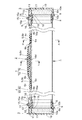
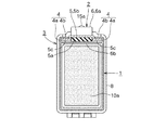
この収納ケースは、金属または硬質合成樹脂材料等により、長手方向の少なくとも一端、本実施形態では左右の両端が開口する角筒状に形成され、かつ釣竿等の長尺物(図示略)を収容しうる左右方向を向くケース本体1と、このケース本体1の上面に設けられた取手装置2と、ケース本体1の左右の端部に設けられた蓋体装置3、3とを備えている。
Hereinafter, an embodiment of the storage case of the present invention will be described with reference to FIGS. 1 to 6.
This storage case is made of metal, a hard synthetic resin material, or the like, and is formed in a square tubular shape with at least one end in the longitudinal direction and both left and right ends open in the present embodiment , and accommodates a long object (not shown) such as a fishing rod. It includes a
ケース本体1の上面には、互いに平行をなして左右方向を向く前後1対のガイドレール4、4が設けられている。
前後のガイドレール4、4は、図4に示すように、ケース本体1の前後の縁より起立する起立片4a、4aと、その上端より互いに対向する方向を向く折曲片4b、4bとからなる、互いに対向する鉤形の断面形状をなしている。
On the upper surface of the
As shown in FIG. 4, the front and
取手装置2は、前後のガイドレール4、4に、その長手方向に摺動可能として装着され、かつケース本体1の上面に対向する下面に、左右方向を向く凹溝5aが設けられた左右1対のスライド片5、5と、左右方向を向く把持部6aの両端に弾性帯板部6b、6bが連設され、この弾性帯板部6b、6bがケース本体1の上面に接触するようにして、上記各スライド片5の凹溝5aを左右方向に摺動可能として挿通し、かつ両弾性帯板部6b、6bの外端部に、スライド片5の凹溝5aからの抜け止め用の上向きの突部6c、6cが設けられた取手6と、両スライド片5、5間であって、かつ取手6の把持部6aの下面とそれに対向するケース本体1の上面との間において、両ガイドレール4、4に、その長手方向に摺動可能として装着されたスペーサ7とを備えている。
The
各スライド片5は金属板よりなり、その断面形状は、図4に示すように、凹溝5aを形成する下向きコ字形部5bの開口縁部に、両ガイドレール4、4の鉤形部分に係合する、前後方向を向く外向き係合片5c、5cを連設したものとしてある。
Each
取手6の把持部6aと弾性帯板部6b、6bと突部6c、6cとは、ゴムまたは軟質合成樹脂材料等により、ほぼ同幅として一体的に形成されている。
把持部6aの下面には、把持部6aを把持し易くするための下向膨出部6dが設けられている。
The
On the lower surface of the
スペーサ7は、図5に示すように、上面が両ガイドレール4の折曲片4b、4bの上面と整合するようにして、それらの間に配設された下向きコ字形部7aと、その開口縁部に、両ガイドレール4、4の鉤形部分に係合する、前後方向を向く外向き係合片7b、7bとからなっている。
スペーサ7の左右方向の長さは、図1〜図3に示すように、取手6の下向膨出部6dがスペーサ7の上面に当接または近接し、取手6全体がほぼ扁平となった不使用時の状態において、左右のスライド片5、5間の間隔より、取手6の弾性帯板部6bの厚さの2倍を差し引いた寸法より、さらに短くしてある。
As shown in FIG. 5, the
As shown in FIGS. 1 to 3, the length of the
取手6が不使用時の状態のときは、取手6を左右に移動させることにより、取手6と左右のスライド片5、5とスペーサ7とを、一体として、両ガイドレール4、4に沿って、そのままの状態で左右方向に摺動させることができる(スペーサ7は、若干遅れて摺動することがある)。
したがって、ケース本体1に対する取手6の取付位置を、運搬時の状況に応じて、都合のいい位置に適宜変更することができる。
例えば、収納ケースを水平にして持ち運ぶときは、取手6を、重心位置であるケース本体1の左右方向のほぼ中央部に位置させて、安定よく提げることができ、また、収納ケースを上下方向に向けて持ち運ぶときは、取手6が重心より上方に位置するように、ケース本体1の長手方向の中央部より一端寄りに位置させて安定よく吊り下げて運ぶことができる。
When the
Therefore, the mounting position of the
For example, when carrying the storage case horizontally, the
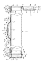
図6に示すように、取手6の把持部6aを把持して、ケース本体1の上面から上方に離れるように引き上げると、左右の弾性帯板部6b、6bが弾性変形しつつ、その外端部同士が、左右のスライド片5、5とともに互いに内方に引き寄せられ、その後、スペーサ7の両端が、互いに引き寄せられた左右の弾性帯板部6b、6bの内面とケース本体1の上面との間に楔入し、その左右の弾性帯板部6b、6bの内面に当接すると、取手6の両端部の互いに近接する方向への移動が阻止されるとともに、スペーサ7の両端に当接した部分から外側の両弾性帯板部6b、6bの下面がケース本体1の上面に圧接させられ、それがブレーキとなって、取手6の取付位置の移動が阻止される。
したがって、取手6を把持して収納ケースを運搬している途中で、取手6の取付位置が不意に変動して、収納ケースの重量バランスが崩れるおそれを防止することができる。
As shown in FIG. 6, when the
Therefore, it is possible to prevent the possibility that the mounting position of the
左右の蓋体装置3、3は、互いに左右対称の同一構造をなしている。
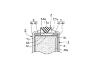
各蓋体装置3は、ケース本体1の各端部に外嵌したほぼ矩形枠状の縁枠材8と、この縁枠材8の下端部に、前後方向を向く軸9をもって枢着され、かつ縁枠材8の開口を閉塞する閉止位置(図3参照)と上記開口を開放する開放位置(図6の右端部参照)とに回動可能とした蓋体10と、蓋体10の閉止時の上端部に前後方向を向く軸11をもって枢着され、蓋体10が閉止位置に位置している状態で、ケース本体1の上面に近接する係合位置とケース本体の上面から離れた解放位置とに回動可能であり、かつ先端部に円形の係合孔12が設けられた係止片13と、ケース本体1の上面に突設され、かつ先端に、南京錠(掛け金式錠前)の掛け金(図示略)が挿通可能な通孔14が設けられた球頭部15aを有し、係止片13を係合位置としたとき、球頭部15aが係止片13の係合孔12と弾性係合するようにした係合ピン15とを備えている。
The left and
Each
蓋体10は、内端部が開口する方形の箱状をなし、その内部には、スポンジ等からなる緩衝材10aが設けられている。
また、蓋体10の開口縁部には、蓋体10の閉止時に、縁枠材8の開口端面に設けた環状溝8aに嵌合する環状突条10bが設けられ、蓋体10の閉止時の密閉性を向上するようにしてある。
The
Further, the opening edge portion of the
縁枠材8の上面には、ケース本体1の中央部に向かって突出する突部8bが設けられており、この突部8bを含む縁枠材8の上面と、蓋体10の閉止時の上面とには、前後幅を係止片13の前後幅と同一か、またはそれよりもわずかに大とした凹入段部16、17が設けられている。
縁枠材8の凹入段部16は、上方と外側方とに開口し、その底面16aにおける外側端寄りの部分には、係合ピン15における球頭部15aから下方に向かってなだらかに拡開するテーパー状の軸部15bが立設されている。
また、凹入段部16の底面16aにおける外側端部には、前後方向を向く突縁部18が設けられている。
A
The recessed
Further, a protruding
蓋体10の凹入段部17は、上方と左右両側方に開口し、その凹入段部17の外側端部内において、係止片13の基端部が軸11をもって蓋体10に枢着されている。
図3に示すように、係止片13は、係合位置に位置しているときは、その上面が、縁枠材8の上面および蓋体10の上面とほぼ整合するようにして縁枠材8の凹入段部16と蓋体10の凹入段部17とに嵌合し、凹入段部16の上方開口部の一部と凹入段部17の上方開口部のほぼ全体を閉塞している。
縁枠材8の凹入段部16の内端部と係止片13の先端との間には、係止片13を係合位置から解放位置に外す際に指を挿入するための空間Sが形成されている。
The recessed
As shown in FIG. 3, when the locking
A space S between the inner end of the recessed
係合位置に位置しているときの係止片13の下面における左右方向の中間部には、係止片13を係合位置としたとき、縁枠材8の突縁部18に弾性係合するようにした前後方向を向く突条19が設けられている。
突条19と突縁部18との弾性係合が外れにくく、しかも円滑に弾性係合させることができるようにするため、突条19の先端部と縁枠材8の先端部とは、図3および図6に示すように、緩やかな曲線をなすフック状に形成するのが好ましい。
When the locking
In order to prevent the elastic engagement between the
左右の蓋体装置3、3は、上記のような構成としてあるので、蓋体10を閉止位置とした後、係止片13に設けた係合孔12を、係合ピン15の球頭部15aに圧嵌して、弾性係合させるだけで、係止片13は係合位置に保持され、蓋体10を閉止位置に確実に保持することができ、また、係止片13を係合ピン15の球頭部15aから離れる方向に回動させるだけで、蓋体10を容易に開くことができる。
係止片13を係合位置に位置させた後、南京錠の掛け金を、係合ピン15の球頭部15aに設けた通孔14に挿通させて、南京錠を施錠することにより、蓋体10を確実に施錠することができる。
しかも、係合ピン15は、縁枠材8に突設するだけでよいので、特許文献1に記載されているリング状の掛け金受けのように、ケース本体1の外面等に回転可能に枢着する必要はなく、蓋体10の取付部分の構造を簡素化することができる。
Since the left and
After the
Moreover, since the engaging
また、係止片13に設けた係合孔12と係合ピン15の球頭部15aとの弾性係合により、係止片13が係合位置から解放位置側に開くのを防止することができ、かつ係止片13の中間部に設けた突条19と縁枠材8に設けた突縁部18との弾性係合により、蓋体10が閉止位置から開放位置側に開くのを防止することができる。
なお、突条19と突縁部18とを省略することができ、この場合には、係合孔12と係合ピン15の球頭部15aとの弾性係合のみにより、係止片13が係合位置から解放位置側に開くのを防止し、かつ蓋体10が閉止位置から開放位置側に開くのを防止することができる。
Further, it is possible to prevent the
The
さらに、係合ピン15および突縁部18を凹入段部16に配設してあるので、それらが外部に大きく突出するのを防止することができ、スマートな外観を有するものとすることができる。
Further, since the engaging
しかも、係止片13を係合位置としたとき、係止片13が、凹入段部16の一部を閉塞するようにして、凹入段部16に嵌合するようにしてあるので、体裁がよい。
また、凹入段部16における、係止片13によって覆われていない部分を、係止片13を係合位置から解放位置に外す際の指の挿入用の空間Sとすることができる。
Moreover, when the locking
Further, the portion of the recessed
縁枠材8は、後述するように省略することもできるが、この縁枠材8に、凹入段部16や係合ピン15および突縁部18を設けておくことにより、この縁枠材8と蓋体10および係止片13等とを予め組み付けて、蓋体装置3を完成させておき、それを、押し出し成形等により形成したケース本体1の端部に取付けるだけで、ケース本体1に特別な加工を施すことなく、簡単に製造することができる。
The
本発明は、上記実施形態のみに限定されるものではなく、特許請求の範囲を逸脱することなく、例えば、次のような幾多の変形した態様での実施が可能である。
(1) ケース本体1の一端のみに蓋体装置3を設け、ケース本体1の他端は、閉塞部材(図示略)をもって閉塞する。
(2) 縁枠材8を省略し、係合ピン15および突縁部18をケース本体1に直接設ける。すなわち、係合ピン15および突縁部18をケース本体1と一体とする。
(3) ケース本体1に凹入段部16と同様の凹入段部を設け、その底面に、係合ピン15および突縁部18を直接設ける。
The present invention is not limited to the above-described embodiment, and can be implemented in a number of modified modes such as the following without departing from the scope of claims.
(1) The
(2) The
(3) The
1 ケース本体
2 取手装置
3 蓋体装置
4 ガイドレール
4a起立片
4b折曲片
5 スライド片
5a凹溝
5b下向きコ字形部
5c外向き係合片
6 取手
6a把持部
6b弾性帯板部
6c突部
6d下向膨出部
7 スペーサ
7a下向きコ字形部
7b外向き係合片
8 縁枠材
8a環状溝
8b突部
9 軸
10 蓋体
10a緩衝材
10b環状突条
11 軸
12 係合孔
13 係止片
14 通孔
15 係合ピン
15a球頭部
15b軸部
16 凹入段部
16a底面
17 凹入段部
18 突縁部
19 突条
S 空間
1
Claims (3)
前記ケース本体の開口を有する側の一端部に外嵌される矩形枠状の縁枠材と、
前記縁枠材の下端部に枢着され、かつ前記ケース本体の前記開口を閉塞する閉止位置と前記開口を開放する開放位置とに回動可能とした蓋体と、
前記蓋体が閉止位置に位置している状態で、前記蓋体の上端部に枢着され、前記ケース本体の上面に近接する係合位置と前記ケース本体の上面から離れた解放位置とに回動可能であり、かつ先端部に円形の係合孔が設けられた係止片と、
前記縁枠材の上面に軸部が立設され、かつ先端に南京錠の掛け金を挿通しうる通孔が設けられた球頭部を有し、前記係止片を係合位置としたとき、前記球頭部が前記係止片の係合孔と弾性係合するようにした係合ピンと、
前記縁枠材の上面に前記係合ピンよりも前記開口に近接する部分に設けた突縁部と、
前記係止片の中間部に、前記係止片を係合位置としたとき、前記突縁部に弾性係合するように設けた突条と、
を備えることを特徴とする収納ケース。 A square tubular case body having an opening at at least one end in the longitudinal direction and accommodating an article inside.
A rectangular frame-shaped edge frame material that is fitted onto one end of the case body on the side having an opening,
Wherein is pivotally secured to the lower end of the edge frame members, and the cover body and the rotatable to an open position for opening the opening and closing position for closing the opening of the case body,
With the lid in the closed position, it is pivotally attached to the upper end of the lid and rotated to an engaging position close to the upper surface of the case body and a release position away from the upper surface of the case body. A locking piece that is movable and has a circular engaging hole at the tip,
When the shaft portion on surface of the edge frame member is erected, and tip has a padlock shackle ball head through holes which can be inserted is provided to the, it was engaged position the locking piece, An engaging pin having the ball head elastically engaged with the engaging hole of the locking piece,
A protruding edge portion provided on the upper surface of the edge frame material in a portion closer to the opening than the engaging pin, and
A ridge provided in the middle portion of the locking piece so as to elastically engage with the ridge portion when the locking piece is in an engaging position.
A storage case characterized by being equipped with.
Priority Applications (1)
| Application Number | Priority Date | Filing Date | Title |
|---|---|---|---|
| JP2016180218A JP6830643B2 (en) | 2016-09-15 | 2016-09-15 | Storage case |
Applications Claiming Priority (1)
| Application Number | Priority Date | Filing Date | Title |
|---|---|---|---|
| JP2016180218A JP6830643B2 (en) | 2016-09-15 | 2016-09-15 | Storage case |
Publications (2)
| Publication Number | Publication Date |
|---|---|
| JP2018042778A JP2018042778A (en) | 2018-03-22 |
| JP6830643B2 true JP6830643B2 (en) | 2021-02-17 |
Family
ID=61693958
Family Applications (1)
| Application Number | Title | Priority Date | Filing Date |
|---|---|---|---|
| JP2016180218A Active JP6830643B2 (en) | 2016-09-15 | 2016-09-15 | Storage case |
Country Status (1)
| Country | Link |
|---|---|
| JP (1) | JP6830643B2 (en) |
Families Citing this family (1)
| Publication number | Priority date | Publication date | Assignee | Title |
|---|---|---|---|---|
| CN110893042A (en) * | 2018-09-12 | 2020-03-20 | 汉立新材料科技有限公司 | Case and bag charging device and contain its case and bag |
Family Cites Families (8)
| Publication number | Priority date | Publication date | Assignee | Title |
|---|---|---|---|---|
| US1623050A (en) * | 1924-12-11 | 1927-04-05 | Frantz Mfg Company | Padlock hasp device |
| JPS5418557Y2 (en) * | 1974-04-30 | 1979-07-12 | ||
| JP3021419U (en) * | 1995-07-20 | 1996-02-20 | 官秀 李 | Bag clasp |
| JP2000168859A (en) * | 1998-11-30 | 2000-06-20 | Yoshino Kogyosho Co Ltd | Container |
| JP4127353B2 (en) * | 2001-12-06 | 2008-07-30 | 株式会社日乃本錠前 | lock |
| US7401698B2 (en) * | 2005-02-22 | 2008-07-22 | Robert Bosch Gmbh | Latch for tool accessory case |
| JP2014047470A (en) * | 2012-08-29 | 2014-03-17 | Nihonkai Shokusan Kogyo:Kk | Structure of storage box cover |
| JP6746950B2 (en) * | 2015-02-26 | 2020-08-26 | 凸版印刷株式会社 | Container with lid |
-
2016
- 2016-09-15 JP JP2016180218A patent/JP6830643B2/en active Active
Also Published As
| Publication number | Publication date |
|---|---|
| JP2018042778A (en) | 2018-03-22 |
Similar Documents
| Publication | Publication Date | Title |
|---|---|---|
| US10420703B1 (en) | Pill container | |
| US8297464B2 (en) | Carrying case with locking latch mechanism | |
| CN104129579B (en) | Plug body of beverage container | |
| JP2020037760A (en) | Protective helmet with lifting mechanism for visor | |
| KR20150086756A (en) | Latching Device for Locker | |
| US9346378B2 (en) | Infant care device | |
| JP6830643B2 (en) | Storage case | |
| CN102281789A (en) | Rope fastener | |
| JP6703464B2 (en) | Storage case with handle | |
| JP4725994B2 (en) | Container with lid | |
| US10676973B2 (en) | Latch hook-type positioning device | |
| KR101646090B1 (en) | Towing hook cap | |
| KR101565309B1 (en) | A door locking device for cavinet | |
| JP5241390B2 (en) | Compact container | |
| JP3224655U (en) | Plug of beverage container and thermos provided with the same | |
| JP4657592B2 (en) | Compact container | |
| JP4188292B2 (en) | Slide fastener for slide fastener with stop device | |
| JP4721215B2 (en) | Container with lid | |
| JP2014079319A (en) | Locking implement for strap | |
| US767045A (en) | Bag-fastener. | |
| TWI600821B (en) | Planar handle to be locked by padlock | |
| JP2005126104A (en) | Cap | |
| KR20140100014A (en) | Products Case for Checking Whether it is opend or not | |
| JP3185569U (en) | Chopstick storage container | |
| JP5241389B2 (en) | Compact container |
Legal Events
| Date | Code | Title | Description |
|---|---|---|---|
| A621 | Written request for application examination |
Free format text: JAPANESE INTERMEDIATE CODE: A621 Effective date: 20190405 |
|
| A977 | Report on retrieval |
Free format text: JAPANESE INTERMEDIATE CODE: A971007 Effective date: 20191212 |
|
| A131 | Notification of reasons for refusal |
Free format text: JAPANESE INTERMEDIATE CODE: A131 Effective date: 20200114 |
|
| A521 | Request for written amendment filed |
Free format text: JAPANESE INTERMEDIATE CODE: A523 Effective date: 20200311 |
|
| A02 | Decision of refusal |
Free format text: JAPANESE INTERMEDIATE CODE: A02 Effective date: 20200901 |
|
| A521 | Request for written amendment filed |
Free format text: JAPANESE INTERMEDIATE CODE: A523 Effective date: 20201201 |
|
| C60 | Trial request (containing other claim documents, opposition documents) |
Free format text: JAPANESE INTERMEDIATE CODE: C60 Effective date: 20201201 |
|
| A911 | Transfer to examiner for re-examination before appeal (zenchi) |
Free format text: JAPANESE INTERMEDIATE CODE: A911 Effective date: 20201209 |
|
| C21 | Notice of transfer of a case for reconsideration by examiners before appeal proceedings |
Free format text: JAPANESE INTERMEDIATE CODE: C21 Effective date: 20201215 |
|
| TRDD | Decision of grant or rejection written | ||
| A01 | Written decision to grant a patent or to grant a registration (utility model) |
Free format text: JAPANESE INTERMEDIATE CODE: A01 Effective date: 20210112 |
|
| A61 | First payment of annual fees (during grant procedure) |
Free format text: JAPANESE INTERMEDIATE CODE: A61 Effective date: 20210113 |
|
| R150 | Certificate of patent or registration of utility model |
Ref document number: 6830643 Country of ref document: JP Free format text: JAPANESE INTERMEDIATE CODE: R150 |
|
| R250 | Receipt of annual fees |
Free format text: JAPANESE INTERMEDIATE CODE: R250 |
|
| R250 | Receipt of annual fees |
Free format text: JAPANESE INTERMEDIATE CODE: R250 |
|
| R250 | Receipt of annual fees |
Free format text: JAPANESE INTERMEDIATE CODE: R250 |