JP6304720B2 - Pachinko machine - Google Patents
Pachinko machine Download PDFInfo
- Publication number
- JP6304720B2 JP6304720B2 JP2016044100A JP2016044100A JP6304720B2 JP 6304720 B2 JP6304720 B2 JP 6304720B2 JP 2016044100 A JP2016044100 A JP 2016044100A JP 2016044100 A JP2016044100 A JP 2016044100A JP 6304720 B2 JP6304720 B2 JP 6304720B2
- Authority
- JP
- Japan
- Prior art keywords
- light guide
- guide plate
- peripheral control
- light
- data
- Prior art date
- Legal status (The legal status is an assumption and is not a legal conclusion. Google has not performed a legal analysis and makes no representation as to the accuracy of the status listed.)
- Active
Links
Images


Description
本発明は、遊技盤面に設定され、かつ弾発された打球が通過可能とされた遊技領域の背面を装飾する装飾体を有するパチンコ遊技機に関する。 The present invention relates to a pachinko gaming machine having a decorative body which is set on a game board surface and decorates the back of a game area through which a bullet hit can be passed.
従来より、遊技機としてのパチンコ機では、遊技盤に区画形成された遊技領域内に遊技球を打ち込み、該遊技領域内に配置された入賞口に遊技球が入賞することで所定数の賞球を遊技者に払い出す遊技内容となっている。このような弾発された打球が通過可能とされた遊技領域を形成する遊技盤は、一般的にベニヤ板から構成され、遊技領域を含む遊技者側と対向する表面部分には、例えば、遊技機種に因んだキャラクタや絵柄が描画された樹脂製の薄板状又はシート状の装飾部材(セル部材)を取り付け、遊技盤面を装飾していた。また、ベニヤ板から構成された遊技盤の盤面ほぼ中央に前後方向に貫通する開口を形成すると共に、該開口を後側から塞ぐように、様々な演出画像を表示可能な演出表示装置(演出表示手段)を取り付けることで、遊技領域内に演出用の画像表示面を臨設させ、遊技領域内での視覚的な興趣の低下を抑制するものが提案されている。また、このように遊技盤に演出表示装置を取り付けた構成としては、遊技領域内に臨設された画像表示面の外周部分に、遊技機の機種を特徴付けるためのキャラクタやロゴ、あるいは可動役物等の外周装飾部材を取り付けることで、画像表示面外周における装飾性の低下を抑制するものが提案されている(例えば、特許文献1参照)。 Conventionally, in a pachinko machine as a gaming machine, a predetermined number of prize balls are obtained by driving a game ball into a game area defined on the game board and winning the game ball in a prize opening arranged in the game area. The game content is to pay out to the player. A game board that forms a game area through which such a hit ball can be passed is generally composed of a plywood board, and a surface portion facing the player side including the game area has, for example, a game machine type. A resin thin plate or sheet-like decorative member (cell member) on which a character or a pattern resulting from the above is drawn is attached to decorate the game board surface. In addition, an effect display device (effect display means) capable of displaying various effect images so as to form an opening penetrating in the front-rear direction substantially at the center of the board surface of the game board composed of a plywood board and closing the opening from the rear side. ) Is provided so that an image display surface for production is provided in the game area, and a decrease in visual interest in the game area is proposed. In addition, as a configuration in which the effect display device is attached to the game board in this way, a character, a logo, a movable accessory, etc. for characterizing the model of the game machine is provided on the outer peripheral portion of the image display surface provided in the game area. The thing which suppresses the fall of the decorating property in an image display surface outer periphery by attaching this outer periphery decoration member is proposed (for example, refer patent document 1).
このため、従来のベニヤ板から構成された遊技盤では、遊技領域には演出装置を配置できないため演出領域が狭い、という問題がある。 For this reason, in the game board comprised from the conventional veneer board, there exists a problem that an effect area is narrow since an effect device cannot be arrange | positioned in a game area.
上記特許文献1に記載の遊技盤では、装飾部材に描かれた絵柄は固定的なものであるため、少なくとも遊技盤を交換するとか、遊技台を入れ替えない限り、遊技領域の背景を一新することができなかった。このため、遊技領域の視覚的興趣の低下を抑止できなかった。遊技者に飽きられないために頻繁に遊技台を入れ替えることは、手間やコスト、遊技場の稼働時間の面で無駄が多い。
In the game board described in
本発明は、これに鑑みてなされたもので、その目的は、遊技盤を新たな態様で装飾することで、興趣の低下を抑制する遊技機を提供することにある。 This invention is made | formed in view of this, The objective is to provide the game machine which suppresses the fall of an interest by decorating a game board in a new aspect .
請求項1に係る遊技機は、
遊技球が流下可能とされた遊技パネルを具備する遊技盤を備えた遊技機において、
前記遊技盤に設けられ、側部から光を入射可能とされた透光性を有する複数の導光板と、
前記遊技盤に設けられ、前記複数の導光板の側部に光を入射させるための複数の光源と、
前記遊技盤に設けられ、所定の演出表示を行う演出表示部と、を備え、
前記複数の導光板のうちの第1の導光板の面部には、第1光源からの光が該第1の導光板の側部に入射されることで表出される第1装飾が設けられ、
前記複数の導光板のうちの第2の導光板の面部には、第2光源からの光が該第2の導光板の側部に入射されることで表出される第2装飾が設けられ、
さらに、当該遊技機は、前記複数の光源の発光制御を行う制御手段を備え、
前記制御手段は、
前記第2光源を消灯した状態で前記第1光源を発光させる第1発光制御と、前記第1光源を消灯した状態で前記第2光源を発光させる第2発光制御とを実行可能であり、
所定時点からの第1時間の経過に基づき前記演出表示部にて第1演出表示が行われるときに前記第1発光制御を実行し、前記第1演出表示に関連して前記第1装飾を表出し、前記第1時間とは異なる第2時間の経過に基づき前記演出表示部にて第2演出表示が行われるときに前記第2発光制御を実行し、前記第2演出表示に関連して前記第2装飾を表出し得ることを特徴とする遊技機。
A gaming machine according to
In a gaming machine equipped with a gaming board having a gaming panel in which gaming balls can flow down,
A plurality of light guide plates provided on the game board and having translucency that allow light to enter from the side portions;
A plurality of light sources provided on the game board and for allowing light to enter the side portions of the plurality of light guide plates;
An effect display unit provided on the game board and performing a predetermined effect display;
Of the plurality of light guide plates, a surface of the first light guide plate is provided with a first decoration that is exposed when light from the first light source is incident on a side of the first light guide plate,
Of the plurality of light guide plates, the second light guide plate is provided with a second decoration that is exposed when light from the second light source is incident on the side of the second light guide plate,
Furthermore, the gaming machine includes a control unit that performs light emission control of the plurality of light sources,
The control means includes
A first light emission control for causing the first light source to emit light with the second light source turned off, and a second light emission control for causing the second light source to emit light with the first light source turned off;
The first light emission control is executed when the first effect display is performed on the effect display unit based on the passage of the first time from a predetermined time point, and the first decoration is displayed in relation to the first effect display. And when the second effect display is performed on the effect display unit based on the passage of a second time different from the first time, the second light emission control is executed, and the second effect display is related to the second effect display. A gaming machine characterized in that the second decoration can be displayed.
請求項1に係る遊技機によれば、遊技盤を新たな態様で装飾することで、興趣の低下を抑制することができる。
According to engagement Ru gaming machine to claim 1, by decorating the game board in a new manner, it is possible to suppress a decrease of the interest.
以下、本発明の実施の形態を図面に基づいて詳細に説明する。図1はパチンコ遊技機を構成する外枠、本体枠、遊技盤、扉枠の前方から見た分解斜視図であり、図2は実施形態におけるパチンコ遊技機を構成する外枠、本体枠、遊技盤、扉枠の後方から見た分解斜視図である。 Hereinafter, embodiments of the present invention will be described in detail with reference to the drawings. FIG. 1 is an exploded perspective view seen from the front of an outer frame, a main body frame, a game board, and a door frame constituting the pachinko gaming machine, and FIG. 2 is an outer frame, main body frame, and game constituting the pachinko gaming machine in the embodiment. It is the disassembled perspective view seen from the back of the board and the door frame.
図1乃至図2において、本実施形態に係るパチンコ遊技機1は、遊技ホールの島(図示しない)に設置される外枠2と、外枠2に開閉自在に軸支され且つ遊技盤4を装着し得る本体枠3と、本体枠3に開閉自在に軸支され且つ遊技盤4に形成されて球が打ち込まれる遊技領域605を遊技者が視認し得る遊技窓101とその遊技窓101の下方に配置され且つ遊技の結果によって払出される球を貯留する貯留皿としての皿ユニット300とを備えた扉枠5と、を備えて構成されている。
1 and 2, a
本体枠3には、上記したように遊技盤4が着脱自在に装着し得る他に、その裏面下部に打球発射装置650と、遊技盤4を除く扉枠5や本体枠3に設けられる電気的部品を制御するための各種の制御基板や電源基板等が一纏めに設けられている基板ユニット1100が取付けられ、本体枠3の後面開口580を覆うカバー体1250が着脱自在に設けられている。更に、扉枠5には、上記した皿ユニット300の他に、遊技窓101を閉塞するようにガラスユニット450と、ハンドル装置400とが設けられている。
As described above, the
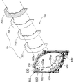
図3は遊技盤を構成する主な部材毎に分解して斜め前から見た斜視図である。本実施形態のパチンコ遊技機1における遊技盤4は、外レール602及び内レール603を有し、遊技者が操作ハンドル部410を操作することで遊技媒体としての遊技球(単に「球」とも称す)が打ち込まれる遊技領域605の外周を区画形成する枠状の前構成部材601と、前構成部材601の後側で遊技領域605を閉鎖するように配置される透明板状の遊技パネル600と、遊技パネル600の外周を覆うと共に遊技パネル600を前側から着脱可能に保持し、前構成部材601の後側に取付けられる枠状のパネルホルダ630と、遊技領域605の外側でアウト口606よりも右側の前構成部材601下部に配置された機能表示ユニット640と、を備えている。
FIG. 3 is a perspective view disassembled for each main member constituting the game board and viewed obliquely from the front. The
この遊技盤4は、主に遊技パネル600の前面側に配置される表ユニット2000と、遊技パネル600の後面側に配置される裏ユニット3000と、裏ユニット3000の後側に遊技者側から視認可能に取り付けられ所定の演出画像を表示可能な液晶表示装置(演出表示装置)1400と、を更に備えている。
The
遊技盤4における表ユニット2000は、遊技領域605内の左右方向略中央でアウト口606の上側に配置され遊技パネル600の前面に支持されるアタッカユニット2100と、アタッカユニット2100の左側で遊技領域605の外周に沿って配置され遊技パネル600の前面に支持されるサイド装飾部材2200と、遊技領域605内の上下方向中央からやや上寄り左側に配置され遊技パネル600の前面に支持されるゲート部材2300と、遊技領域605の略中央部分に配置され遊技パネル600に支持される枠状のセンター役物2400と、を備えている。なお、符号2407は、センター役物2400の後端に取付けられ、前後方向へ貫通した枠内のほとんどを閉鎖する透明板状の奥板である。
The
また、遊技盤4における裏ユニット3000は、パネルホルダ630の後側に取付けられる枠状の裏前ユニット3000aと、裏前ユニット3000aの後側に取付けられる裏後ユニット3000bと、を備えている。この裏後ユニット3000bの後面には、液晶表示装置1400が脱着可能に取付けられるようになっており、裏前ユニット3000a及びセンター役物2400の枠内を通して、表示された演出画像が遊技者側から視認できるようになっている。
The
本実施形態の遊技盤4における裏ユニット3000は、前後に分割された形態となっており、前側の裏前ユニット3000aと後側の裏後ユニット3000bとに分かれている。この裏ユニット3000における裏前ユニット3000aは、センター役物2400よりも外側で透明な遊技パネル600の後側を装飾する裏前上部装飾部材3020、裏前左部装飾部材3030、及び裏前下部装飾部材3040を主に備えている。また、裏ユニット3000における裏後ユニット3000bは、遊技パネル600の後側で液晶表示装置1400の外周に配置される上部可動装飾体ユニット3200、サイド可動装飾体ユニット3400、及び下部可動装飾体ユニット3600を主に備えている。なお、液晶表示装置1400は、裏後ユニット3000bにおける裏箱621を構成する裏箱本体3100の後側に着脱可能に取付けられている。
The
盤用基板ホルダ623は、パネルホルダ630の後側に取付固定されるものであり、図示するように、前方及び上方が開放された箱状とされ、その底部が左右方向の略中央で前側に向かって低くなるように傾斜しており、遊技パネル600の後側に排出された遊技球を受け取った上で、左右方向の略中央から下方へ排出することができるようになっている。盤用基板ホルダ623の後面には、主制御基板ボックス624が取付固定されている。
The
遊技盤4における遊技パネル600は、その外形が遊技領域605よりも若干大きい多角形状とされており、アクリル樹脂、ポリカーボネイト樹脂、ポリアリレート樹脂、メタクリル樹脂等の透明な合成樹脂板により形成されている。なお、遊技パネル600の板厚は、パネルホルダ630よりも薄く、図示しない障害釘を植設しても十分に保持可能な必要最低限の厚さ(8〜10mm)とされている。
The
更に、遊技パネル600には、センター役物2400及びアタッカユニット2100等が備えられるように内形が所定形状で前後方向に貫通する開口部600eが複数形成されていると共に、それらを固定するための固定孔が適宜位置に形成されている。なお、これら開口部600eは、遊技パネル600の上下左右方向の外周に対して貫通しないような形状となっており、遊技パネル600の外周が繋がっているので、開口部600eによって遊技パネル600の強度が低下するのを抑制するようになっている。
Further, the
図示しないが、遊技パネル600の前面(遊技領域605が形成される側)には遊技球の流下方向を変化させ、遊技球の挙動を面白くする複数の障害釘が所定のゲージ配列で植設されている。なお、実施形態においては、弾発された打球が通過可能とされた遊技領域605は、主として遊技パネル600の中央部分の開口部600eの上方、左方及び下方に亘って形成されている。また、透明な遊技パネル600の後面には、遊技領域605の背面を絵柄によって装飾するセル部700(可変装飾表示体)が設けられる。
Although not shown in the drawing, a plurality of obstacle nails are implanted in a predetermined gauge arrangement on the front surface of the game panel 600 (the side where the
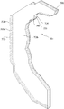
図4は、前構成部材601及びセル部700を前方から見た分解斜視図である。セル部700は、透明な遊技パネル600に区画形成された遊技領域605の後方(後面)において該遊技領域605に臨ませて配置されると共に、側面を導光入射面とされ、かつ前面を導光出射面とされた透光性を有する合成樹脂製の導光板が前後方向に複数枚層状に重ね合わされてなる積層導光体701を備えている。
FIG. 4 is an exploded perspective view of the
図5は積層導光体701の斜視図である。本実施形態の積層導光体701は、正面視で同じ形状で同じ大きさであり、同じ厚みのアクリル樹脂製よりなる前導光板702、中導光板703、後導光板704の3枚が前後方向に層状に重ね合わされてなる。各導光板702〜704は、遊技パネル600の後面において遊技領域605の外周縁に沿って配置される多角形状をなす外側面を導光入射面702a〜704aとされ、前面を導光出射面702b〜704bとされている。
FIG. 5 is a perspective view of the laminated
また、積層導光体701の後面には、正面視で各導光板702〜704と同じ形状で同じ大きさであり、厚みは各導光板702〜704よりも薄い、黒色の樹脂製の遮光板705が配置されている。遮光板705は後方に光が漏れるのを防ぐとともに、黒色とすることで後述の背景絵柄を視認し易くするものである。
Further, the rear surface of the laminated
各導光板702〜704には、光の散乱によって表出する各背景絵柄が記録されると共に、各背景絵柄は互いに異なる絵柄とされている。実施形態では、各導光板702〜704の裏面に、導光印刷により各背景絵柄が記録されている。なお、各背景絵柄の記録方式は、導光印刷ではなく、彫り込みにより、背景絵柄を直接導光板702〜704の裏面に記録してもよい。
Each of the
図6は前導光板702に記録された背景絵柄の一例を示す正面図である。また、図7は中導光板703に記録された背景絵柄の一例を示す正面図である。図6に示すように、前導光板702には、遊技者に春をイメージさせるように、「桜」の背景絵柄が記録されている。また、図7に示すように、中導光板703には、遊技者に夏をイメージさせるように、「橋と夜空に打ち上がる花火」の背景絵柄が記録されている。また、図示は省略するが、後導光板704には、遊技者に秋をイメージさせるように、「紅葉(モミジの葉と銀杏の葉)」の背景絵柄が記録されている。
FIG. 6 is a front view showing an example of the background pattern recorded on the front
図8はセル部700の正面図である。また、図9は遊技パネル600及びセル部700の断面図である。図8〜図9に示すように、各導光板702〜704の導光入射面702a〜704aには、各導光板702〜704に対応して設けられると共に、各導光板702〜704へそれぞれ光を入射するための各光源としての複数のLED707が回路基板上に設けられた複数のLED基板706a〜706eが配設されている。なお、各LED基板706a〜706e上のLED707の配置構成は同じである。
FIG. 8 is a front view of the
図10はLED基板706の正面図である。図10においてLED基板706の左側に配置されたLED群は、前導光板702の外側面に沿って配置される前導光板LED群708である。また、LED基板706の中程に配置されたLED群は、中導光板703の外側面に沿って配置される中導光板LED群709である。さらに、LED基板706の右側寄りに配置されたLED群は、後導光板704の外側面に沿って配置される後導光板LED群710である。
FIG. 10 is a front view of the
なお、中導光板LED群709の各LEDは、各導光板702〜704の厚み寸法が比較的薄く、各LEDが配置しずらくなることを避けるために、水平方向において前導光板LED群708の各LED及び後導光板LED群710の各LEDに対して重ならないように上下方向に位置をずらして配置してある。また、実施形態のLED707はフルカラーLEDで構成してあるが、フルカラーLEDである必要はなく、単色LEDであってもよい。
In addition, each LED of the middle light guide
前導光板LED群708を点灯し(例えば、ピンクで点灯し)、中導光板LED群709及び後導光板LED群710を消灯することで、前導光板702の外側面から入射した光が導光印刷された背景絵柄に当って散乱し、散乱した光が前面の導光出射面702bから出射することによって「桜」の背景絵柄が表出する。なお、導光出射面702bから出射した光は、遊技パネル600を透過する。これにより、前導光板702に表出した「桜」の背景絵柄は、透明な遊技パネル600を通して遊技者に視認される。
The front light guide
また、上述の点灯状態から、中導光板LED群709を点灯し(例えば、花火の部分をイエローで点灯し、橋の部分をブルーで点灯し)、前導光板LED群708及び後導光板LED群710を消灯する点灯状態に切り換えることで、中導光板703の外側面から入射した光が導光印刷された背景絵柄に当って散乱し、散乱した光が前面の導光出射面703bから出射することによって「橋と夜空に打ち上がる花火」の背景絵柄が表出する。なお、導光出射面703bから出射した光は、前導光板702を透過し、さらに遊技パネル600を透過する。これにより、中導光板703に表出した「橋と夜空に打ち上がる花火」の背景絵柄は、透明な遊技パネル600を通して遊技者に視認される。
Further, from the above-described lighting state, the middle light guide
また、上述の点灯状態から、後導光板LED群710を点灯し、前導光板LED群708及び中導光板LED群709を消灯する点灯状態に切り換えることで、後導光板704の外側面から入射した光が導光印刷された背景絵柄に当って散乱し、散乱した光が前面の導光出射面704bから出射することによって「紅葉」の背景絵柄が表出する。なお、導光出射面704bから出射した光は、中導光板703及び前導光板702を透過し、さらに遊技パネル600を透過する。これにより、後導光板704に表出した「紅葉」の背景絵柄は、透明な遊技パネル600を通して遊技者に視認される。
In addition, the rear light guide
次に、上述のセル部700を備えた実施形態のパチンコ遊技機の制御系について説明する。実施形態のパチンコ遊技機は、概略として、遊技状態を制御する主制御基板と、主制御基板から送信されたコマンド(表示コマンド)に応じて液晶表示装置1400における演出表示態様や各種報知表示態様に関わる制御と、セル部700における遊技領域の背景絵柄を刷新する制御と、扉枠5や遊技盤4の装飾用LEDに関わる制御と、出力音声出力に関わる制御と、を行う周辺制御基板と、を備えている。
Next, a control system of the pachinko gaming machine according to the embodiment including the
[周辺制御基板]
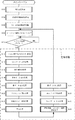
図11は主として周辺制御基板を示す要部ブロック図である。周辺制御基板4140は、図11に示すように、主制御基板4100からのコマンドに基づいて演出制御を行う周辺制御部4150と、この周辺制御部4150からの制御データに基づいて液晶表示装置1400の描画制御と、高音質の演奏を行う液晶・音制御部4160と、RTC制御部4190と、を備えている。
[Peripheral control board]
FIG. 11 is a principal block diagram mainly showing the peripheral control board. As shown in FIG. 11, the peripheral control board 4140 includes a peripheral control unit 4150 that performs effect control based on a command from the
[周辺制御部4150]
演出制御を行う周辺制御部4150は、図11に示すように、マイクロプロセッサとしての周辺制御MPU4150aと、各種処理プログラム、各種コマンド及び各種スケジューラを記憶する周辺制御ROM4150bとを備えている。周辺制御ROM4150bには、例えば、セル部700の前導光板LED群708、中導光板LED群709及び後導光板LED群710の点灯データや、液晶表示装置1400に描画する画面を生成するための各種プログラムのほかに、表示コマンドと対応するスケジュールデータ等が複数記憶されている。スケジュールデータは、画面の構成を規定する画面データが時系列に配列されて構成されており、液晶表示装置1400に描画する画面の順序が規定されている。
[Peripheral control unit 4150]
As shown in FIG. 11, the peripheral control unit 4150 that performs the effect control includes a
周辺制御MPU4150aは、パラレルI/Oポート、シリアルI/Oポート等を複数内蔵しており、主制御基板4100から送信された各種コマンドを受信すると、この各種コマンドに基づいて、遊技盤4の各装飾基板に設けた複数のLED等への点灯信号、点滅信号又は階調点灯信号を出力するための遊技盤側発光データをランプ駆動基板用シリアルI/Oポートからランプ駆動基板4170に送信する。
また、実施形態の周辺制御MPU4150aは,後述の時刻を計時する時刻計時手段の時刻情報が予め定めた条件になると、1つの導光板(例えば、前導光板702)に記録された背景絵柄(「桜」)が光によって表出している状態から、これとは別の導光板(例えば、中導光板703)に記録された背景図柄(「橋と夜空に打ち上がる花火」)を表出させて、遊技領域605の背景絵柄を刷新する背景切換手段を備えている。
In addition, the
ランプ駆動基板4170には、周辺制御基板4140の周辺制御MPU4150aから出力された8ビット単位のシリアルの駆動信号に基いて、導光板702〜704に対して配備された各LED基板706に対して出力する8ビットのパラレル駆動信号を複数生成する駆動信号生成手段が搭載されている。
The lamp driving board 4170 outputs to each
図示を省略しているが、前記駆動信号生成手段は、例えば、8ビット単位のシリアルの駆動信号についてカスケード接続され、かつクロック信号について並列に接続され、かつラッチ信号について並列に接続された複数のシリアル/パラレルICと、複数のシリアル/パラレルICのそれぞれにベースが接続された複数のトランジスタ(ドライバ)とを備え、複数のトランジスタのエミッタがアースに接続されている。また、LED点灯用の電圧と複数のトランジスタのコレクタとの間に、LED基板に実装された各LEDおよび電流制限用の各抵抗がコネクタ(図示せず)及びハーネス(図示せず)を介して接続されている。 Although not shown, the drive signal generation means includes, for example, a plurality of cascade-connected 8-bit serial drive signals, parallel-connected clock signals, and parallel-connected latch signals. A serial / parallel IC and a plurality of transistors (drivers) each having a base connected to each of the plurality of serial / parallel ICs, the emitters of the plurality of transistors being connected to the ground. Also, between the LED lighting voltage and the collectors of the plurality of transistors, each LED mounted on the LED substrate and each current limiting resistor are connected via a connector (not shown) and a harness (not shown). It is connected.
各シリアル/パラレルICは、シフトレジスタとラッチ回路を組み合わせてなるもので、ラッチ信号をハイレベルとした上で、クロック信号の立ち上がりに同期してシリアルデータを1ビット分シフトレジスタ(8ビット構成)に取り込む。また、ラッチ信号をローレベルにすることにより、シフトレジスタの内容がラッチ回路に転送され、8ビットのパラレルデータとして出力される。さらに、さらに、クロック信号の立ち上がりに同期して、1ビットづつシリアルデータ信号を出力するものである。 Each serial / parallel IC is a combination of a shift register and a latch circuit. The latch signal is set to high level, and serial data is shifted by one bit in synchronization with the rising edge of the clock signal (8-bit configuration). Into. Further, by setting the latch signal to a low level, the contents of the shift register are transferred to the latch circuit and output as 8-bit parallel data. Further, the serial data signal is output bit by bit in synchronization with the rising edge of the clock signal.
このように、各シリアル/パラレルICは、8ビット単位のシリアルの駆動信号、クロック信号及びラッチ信号に基づいて前記8ビットのパラレル駆動信号を生成して前記各トランジスタに与える。各トランジスタは、前記各シリアル/パラレルICによって与えられたパラレルの各駆動信号によりオンし、LED基板706に実装された各LEDに対してLED点灯用の電圧を印加する。これにより、LED基板706に実装された各LEDに電流が流れて点灯する。
As described above, each serial / parallel IC generates the 8-bit parallel drive signal based on the 8-bit serial drive signal, the clock signal, and the latch signal, and supplies the generated parallel drive signal to the transistors. Each transistor is turned on by each parallel drive signal given by each serial / parallel IC, and applies an LED lighting voltage to each LED mounted on the
また、周辺制御MPU4150aは、各種コマンドに基づいて、遊技盤4に設けた各種可動体を作動させるモータやソレノイド等の電気的駆動源への駆動信号を出力するための遊技盤側モータ駆動データをモータ駆動基板用シリアルI/Oポートからモータ駆動基板4180に送信する。さらに、扉枠5に設けたダイヤル駆動モータ等の電気的駆動源への駆動信号を出力するための扉側モータ駆動データと、扉枠5の各装飾基板に設けた複数のLED等への点灯信号、点滅信号又は階調点灯信号を出力するための扉側発光データと、から構成される扉側モータ駆動発光データを枠装飾駆動アンプ基板用シリアルI/Oポートから枠周辺中継端子板868、そして周辺扉中継端子板882を介して枠装飾駆動アンプ基板194に送信する。
In addition, the
主制御基板4100からの各種コマンドは、周辺制御MPU4150aの主制御基板用シリアルI/Oポートに入力されている。また、ハンドル装置400に設けられた、ダイヤル操作部の回転(回転方向)を検出するための回転検出スイッチからの検出信号、及び押圧操作部の操作を検出するための押圧検出スイッチからの検出信号は、枠装飾駆動アンプ基板194に設けた図示しない扉側シリアル送信回路でシリアル化され、このシリアル化された操作ユニット検出データが扉側シリアル送信回路から、周辺扉中継端子板882、そして枠周辺中継端子板868を介して周辺制御MPU4150aの操作ユニット検出用シリアルI/Oポートに入力されている。
Various commands from the
遊技盤4に設けた各種可動体の原位置を検出するための各種原位置検出スイッチからの検出信号は、モータ駆動基板4180を介して周辺制御MPU4150aの遊技盤用パラレルI/Oポートに入力されている。
Detection signals from various original position detection switches for detecting the original positions of various movable bodies provided on the
なお、周辺制御部4150は、周辺制御MPU4150aに内蔵されたウォッチドックタイマ(以下、「周辺制御内蔵WDT」と記載する。)のほかに、図示しない、外部ウォッチドックタイマ(以下、「周辺制御外部WDT」と記載する。)も備えており、周辺制御MPU4150aは、周辺制御内蔵WDTと周辺制御外部WDTとを併用して自身のシステムが暴走しているか否かを診断している。
In addition to the watchdog timer (hereinafter referred to as “peripheral control built-in WDT”) built in the
[液晶・音制御部4160]
液晶表示装置1400の描画制御と高音質の演奏を行う液晶・音制御部4160は、図11に示すように、液晶表示装置1400を表示制御するVDP(Video Display Processorの略)4160aと、液晶表示装置1400に表示される画面の各種のキャラクタデータを記憶するキャラROM4160cとを備えている。
[Liquid Crystal / Sound Control Unit 4160]
As shown in FIG. 11, a liquid crystal /
なお、VDP4160aは、高音質の演奏を行う音制御部4160bを内蔵している。また、キャラROM4160cには、各種のキャラクタデータのほかに、音楽及び効果音等の音情報が記憶されている。
The VDP 4160a includes a
周辺制御部4150の周辺制御MPU4150aは、表示コマンドと対応するスケジュールデータの先頭の画面データを周辺制御ROM4150bから抽出してVDP4160aに出力した後に、先頭の画面データに続く次の画面データを周辺制御ROM4150bから抽出してVDP4160aに出力する。このように、周辺制御MPU4150aは、スケジュールデータにおいて時系列に配列された画面データを、先頭の画面データから1つずつ周辺制御ROM4150bから抽出してVDP4160aに出力する。
The
VDP4160aは、周辺制御MPU4150aから出力された画面データが入力されると、この入力された画面データに基づいてキャラROM4160cからキャラクタデータを抽出してスプライトデータを作成して液晶表示装置1400に表示する1画面分(1フレーム分)の描画データを生成し、この生成した描画データを液晶表示装置1400に出力する。またVDP4160aは、1画面分(1フレーム分)の描画データを液晶表示装置1400に出力すると、周辺制御MPU4150aからの画面データを受け入れることが可能である旨を伝えるVブランク割り込み信号を周辺制御MPU4150aに出力する。
When the screen data output from the
なお、VDP4160aは、フレームバッファ方式が採用されている。この「フレームバッファ方式」とは、液晶表示装置1400の画面に描画する1画面分の描画データをフレームバッファに保持し、このフレームバッファに保持した1画面分の描画データを液晶表示装置1400に出力する方式である。
The VDP 4160a employs a frame buffer method. In this “frame buffer method”, drawing data for one screen to be drawn on the screen of the liquid
また、VDP4160aは、周辺制御MPU4150aからの音指令に基づいてキャラROM4160cから音情報を抽出し、枠周辺中継端子板868、そして周辺扉中継端子板882を介して本体枠3に設けたスピーカから各種演出に合わせた音楽及び効果音等が流れるよう制御を行うとともに、枠周辺中継端子板868、周辺扉中継端子板882、そして枠装飾駆動アンプ基板194を介して扉枠5に設けたスピーカから各種演出に合わせた音楽及び効果音等が流れるよう制御を行う。
Further, the VDP 4160a extracts sound information from the character ROM 4160c based on a sound command from the
[RTC制御部4190]
また、実施形態の周辺制御MPU4150aは、時刻情報取得手段として時刻情報を取得することが可能な外付けのリアルタイムクロック(以下、「RTC」という)4192を備えている。図示していないが、RTC4192は、レジスタ回路、クロック入力回路、クロック出力回路、割り込み出力回路、データ入出力回路、および、制御回路を含む。
[RTC control unit 4190]
Further, the
周辺制御部4150は、電源バックアップされていないため、遊技機の電源断の場合、電源オフとなる。したがって、内蔵RTC(図示せず)は、遊技機の電源断の期間は計時情報およびカレンダー情報を失う。RTC制御部4190の外付けのRTC4192から得られる時刻情報は、演出効果を高めるための表示に用いるため、周辺制御基板4140にRTC4192が配置されている。
Since the peripheral control unit 4150 is not backed up, the power is turned off when the gaming machine is powered off. Therefore, the built-in RTC (not shown) loses timekeeping information and calendar information during the period when the gaming machine is powered off. Since the time information obtained from the
RTC4192は、時計・カレンダー機能を備える。時計・カレンダー機能は、年,月,日,時,分,秒をカウントする計時を行う機能である。また、必要に応じて、曜日までカウントするものを用いてもよい。RTC制御部4190はRTC4192の計時計測を正確な値に設定するために用いる装置を備えることができる。正確な時刻情報を設定するには、例えば、GPS衛星からの時刻情報を用いることができる。
The
RTC制御部4190には、RTC4192、および、RTC4192を駆動するための電池4194が設けられている。電池4194を備えることによって、電源基板(図示せず)の電源遮断時においてもRTC4192は計時、および、カレンダー機能を中断することがない。
The RTC control unit 4190 is provided with an
電池4194としては一次電池(例えばボタン電池)であってもよいし、充電可能な二次電池、これによって、バックアップ電源を配置する必要がなく周辺制御基板4140の構成が複雑化するのを避けることができる。あるいは、電源基板にRTC4192のバックアップ電源を配置してもよい。この場合には大容量のキャパシタを用いることによって、一次電池の欠点である電池の消耗による交換作業をしなくてよい。なお、電池4194は、RAM4196のバックアップ電源としても用いられる。
The
RTC4192を時刻情報およびカレンダー情報の保持に限定して使用することによって、RTC4192の消費電力を大幅に減少することができ、ボタン電池などのバックアップ電源の長寿命化を図ることができる。
By using the
遊技機はRTC4192を備えることによって、年・月・日・時・分・秒(カレンダー情報と時刻情報)を特定する機能を備える。即ち、周辺制御基板4140の周辺制御MPU4150aは、遊技機の電源投入時に、RTC4192から時刻情報およびカレンダー情報を取得して、周辺制御MPU4150aの内蔵のRAMの所定エリアに設定された時刻情報記憶部およびカレンダー情報記憶部に記憶する。時刻情報およびカレンダー情報をセットした後には、RTC4192からの時刻情報およびカレンダー情報を読み出すのではなく、周辺制御MPU4150aが、時刻情報記憶部およびカレンダー情報記憶部に記憶された時刻情報およびカレンダー情報を所定の処理周期で更新する(時刻を計時する時刻計時手段)。
By providing the
これによって、時刻情報やカレンダー情報を用いた演出を行う際に、その都度、RTC4192に時刻情報およびカレンダー情報を問い合わせる必要がなくなり、演出を記憶した時刻情報やカレンダー情報によって行うことができ、演出のための処理速度が低下することが防止され、従来不可能であった多様な演出を実行できる。
This eliminates the need to inquire about the time information and calendar information from the
なお、島に設置された遊技機は、遊技機の電源のオン・オフに関わらず、遊技中は常に同一の時刻情報によって演出を行うことができ、計時結果が予め定められた時期的条件を満たすと、複数の遊技機が設置されている島(遊技機設置島)全体の前記複数の遊技機を一斉に演出を実行する構成を備えることができる。島毎に同じ演出を実行することによって、演出が実行されるタイミングを確認しやすくなり、RTC4192について狂いが生じているかどうかの判断もし易くなる。さらに、島毎に異なるデモンストレーション、島毎に時差を備えたデモンストレーションを実行できる。このように、多種多様な演出を実行することができる。
It should be noted that the gaming machines installed on the island can always produce effects with the same time information during gaming, regardless of whether the gaming machine power is on or off, and the timing result is determined in advance. When satisfied, a configuration can be provided in which the plurality of gaming machines on the entire island (gaming machine installation island) where a plurality of gaming machines are installed are performed together. By executing the same effect for each island, it becomes easier to confirm the timing at which the effect is executed, and it is also easy to determine whether or not the
[周辺制御基板4140の各種制御処理]
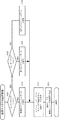
次に、図11に示した、主制御基板4100(主制御MPU4100)から各種コマンドを受信する周辺制御MPU4150a(以下、単に周辺制御MPUという)が実行する各種処理について、図12〜図17を参照して説明する。図12は周辺制御MPUが実行する処理のメインルーチンを示すフローチャートである。
[Various control processes of the peripheral control board 4140]
Next, various processes executed by the
[メインルーチン]
パチンコ遊技機1に電源が投入されると(周辺制御内蔵WDTまたは周辺制御外部WDTにより出力されたリセット信号が入力されると)、周辺制御MPUは、メインルーチンの実行を開始する。周辺制御MPUは、まず、初期設定処理を行う(ステップS02)。この初期設定処理は、周辺制御MPU4150aを初期化する処理と、リセット後のウェイトタイマを設定する処理等を行う。
[Main routine]
When power is turned on to the pachinko gaming machine 1 (when a reset signal output from the peripheral control built-in WDT or the peripheral control external WDT is input), the peripheral control MPU starts executing the main routine. The peripheral control MPU first performs an initial setting process (step S02). This initial setting processing includes processing for initializing the
なお、周辺制御MPUは、この初期設定処理で、まず自身を初期化する処理を行うことによって、主制御基板4100から出力される遊技演出の制御に関するコマンドやパチンコ遊技機1の状態に関するコマンド等の各種コマンドを受信することができる状態となる。この周辺制御MPUを初期化する処理にかかる時間は、マイクロ秒(μs)オーダーであり、極めて短い時間で周辺制御MPUを初期化することができ、主制御基板4100の主制御MPUの初期化処理が終了するよりも早く、周辺制御基板4140は主制御基板4100から送信されるコマンドを取りこぼすことがないようになっている。
In this initial setting process, the peripheral control MPU first performs a process of initializing itself, so that a command related to control of game effects output from the
ステップS02に続いて、現在時刻情報取得処理を行う(ステップS04)。すなわち、外付けのRTC4192から現在時刻情報及びカレンダー情報を取得して、内蔵RAMの所定エリアに設定された現在時刻データ記憶部及びカレンダー情報記憶部に保存する。なお、周辺制御MPUが、RTC4192から時刻情報およびカレンダー情報を取得するのは、電源投入時の1回のみである。次いで、周辺制御MPUはセル背景絵柄決定処理を行う(ステップS06)。
Subsequent to step S02, a current time information acquisition process is performed (step S04). That is, current time information and calendar information are acquired from an
[セル背景絵柄決定処理]
図13は周辺制御MPUが実行するセル背景絵柄決定処理のサブルーチンを示すフローチャートである。セル背景絵柄決定処理を開始すると、周辺制御MPUは内蔵RAMのカレンダー情報記憶部に記憶したカレンダー情報が、予め定めた条件1に合致しているか否かを判別する(ステップA01)。予め定めた条件1は、カレンダー情報と比較される月日情報であり、実施形態では、例えば、4月1日から6月30日迄、という条件に設定されているものとする。
[Cell background pattern determination processing]
FIG. 13 is a flowchart showing a subroutine of cell background picture determination processing executed by the peripheral control MPU. When the cell background pattern determination process is started, the peripheral control MPU determines whether or not the calendar information stored in the calendar information storage unit of the built-in RAM matches a predetermined condition 1 (step A01). The
カレンダー情報記憶部に記憶したカレンダー情報が、予め定めた条件1に合致していると判別した場合、実施形態では、前導光板702に記録された背景絵柄「桜」を遊技領域605に表出するものとする。周辺制御MPUはステップA02に進み、周辺制御ROM4150bに記憶された前導光板背景絵柄表示用データの先頭アドレス(例えば、AAAA)を内蔵RAMに設定された背景絵柄表示用データのアドレス記憶部にセットする(ステップA02)。
When it is determined that the calendar information stored in the calendar information storage unit matches the
図15は、周辺制御ROM4150bに記憶された前導光板背景絵柄表示用データ、中導光板背景絵柄表示用データ及び後導光板背景絵柄表示用データの記憶状態を示す図である。なお、前導光板背景絵柄表示用データ、中導光板背景絵柄表示用データ及び後導光板背景絵柄表示用データはすべて同じ大きさである。前導光板背景絵柄表示用データは、前導光板LED群708を全点灯し、中導光板LED群709及び後導光板LED群710を消灯させるデータであり、前導光板LED群点灯データ、中導光板LED群消灯データ及び後導光板LED群消灯データにより構成されている。
FIG. 15 is a diagram showing a storage state of the front light guide plate background pattern display data, the middle light guide plate background pattern display data, and the rear light guide plate background pattern display data stored in the peripheral control ROM 4150b. The front light guide plate background pattern display data, the middle light guide plate background pattern display data, and the rear light guide plate background pattern display data all have the same size. The front light guide plate background picture display data is data that turns on the front light guide
次いで、周辺制御MPUはセルモードフラグに「1」をセットする(ステップA03)。ここで、セルモードフラグは、周辺制御MPUが前導光板702、中導光板703及び後導光板704のうちの何れの背景絵柄が遊技領域605に表出されているのかを識別するためのフラグであり、「1」で前導光板702の背景絵柄であることを表し、「2」で中導光板703の背景絵柄であることを表し、「3」で後導光板704の背景絵柄であることを表す。ステップA03の処理後、周辺制御MPUはメインルーチンにリターンする。
Next, the peripheral control MPU sets “1” in the cell mode flag (step A03). Here, the cell mode flag is a flag for the peripheral control MPU to identify which background pattern of the front
一方、ステップA01において、カレンダー情報記憶部に記憶したカレンダー情報が、予め定めた条件1に合致しないと判別した場合、周辺制御MPUはステップA04に進み、内蔵RAMのカレンダー情報記憶部に記憶したカレンダー情報が、予め定めた条件2に合致しているか否かを判別する(ステップA04)。予め定めた条件2も、カレンダー情報と比較される月日情報であり、実施形態では、例えば、7月1日から9月30日に設定されているものとする。
On the other hand, if it is determined in step A01 that the calendar information stored in the calendar information storage unit does not match the
カレンダー情報記憶部に記憶したカレンダー情報が、予め定めた条件2に合致していると判別した場合、実施形態では、中導光板703に記録された背景絵柄「橋と夜空に打ち上がる花火」を遊技領域605に表出するものとする。周辺制御MPUはステップA05に進み、周辺制御ROM4150bに記憶された中導光板背景絵柄表示用データの先頭アドレス(例えば、BBBB)を内蔵RAMに設定された背景絵柄表示用データのアドレス記憶部にセットする(ステップA05)。
When it is determined that the calendar information stored in the calendar information storage unit matches the predetermined condition 2, in the embodiment, the background pattern “fireworks rising in the bridge and the night sky” recorded on the middle
図15に示すように、中導光板背景絵柄表示用データは、前導光板LED群708を消灯し、中導光板LED群709を全点灯し、後導光板LED群710を消灯させるデータであり、前導光板LED群消灯データ、中導光板LED群点灯データ及び後導光板LED群消灯データにより構成されている。次いで、周辺制御MPUはセルモードフラグに「2」をセットし(ステップA06)、メインルーチンにリターンする。
As shown in FIG. 15, the middle light guide plate background pattern display data is data that turns off the front light guide
ステップA04において、カレンダー情報記憶部に記憶したカレンダー情報が、予め定めた条件2に合致しないと判別した場合、すなわち、カレンダー情報が予め定めた条件1及び条件2に合致しない場合、換言すると、カレンダー情報が4月1日から9月30日迄という条件に合致しない場合、即ち、カレンダー情報が10月1日から3月31日迄の場合、実施形態では、後導光板704に記録された背景絵柄「紅葉(モミジの葉と銀杏の葉)」を遊技領域605に表出するものとする。周辺制御MPUはステップA07に進み、周辺制御ROM4150bに記憶された後導光板背景絵柄表示用データの先頭アドレス(例えば、CCCC)を内蔵RAMに設定された背景絵柄表示用データのアドレス記憶部にセットする(ステップA07)。
If it is determined in step A04 that the calendar information stored in the calendar information storage unit does not match the predetermined condition 2, that is, if the calendar information does not match the
図15に示すように、後導光板背景絵柄表示用データは、前導光板LED群708を消灯し、中導光板LED群709を消灯し、後導光板LED群710を全点灯させるデータであり、前導光板LED群消灯データ、中導光板LED群消灯データ及び後導光板LED群点灯データにより構成されている。次いで、周辺制御MPUはセルモードフラグに「3」をセットし(ステップA08)、メインルーチンにリターンする。
As shown in FIG. 15, the rear light guide plate background picture display data is data that turns off the front light guide
[メインルーチンのつづき]
メインルーチンに戻ると、周辺制御MPUは、Vブランク検知フラグを0クリアする(ステップS08)。ここで、Vブランク検知フラグは、周辺制御MPUが後述する定常処理(実施形態では33.3ms毎に実行開始)の実行を開始するのか否かを判別するためのフラグであり、VDP4160aから出力されるVブランク割り込み信号により、Vブランク検知フラグが「1(実行開始)」にセットされる。
[Continuation of main routine]
When returning to the main routine, the peripheral control MPU clears the V blank detection flag to 0 (step S08). Here, the V blank detection flag is a flag for determining whether or not the peripheral control MPU starts execution of a steady process (execution start every 33.3 ms in the embodiment) described later, and is output from the VDP 4160a. In response to the V blank interrupt signal, the V blank detection flag is set to “1 (execution start)”.
ステップS08でVブランク検知フラグを0クリアした後、周辺制御MPUは、Vブランク検知フラグが「1(実行開始)」であるか否かを判別する(ステップS10)。周辺制御MPUは、Vブランク検知フラグが「1」にセットされるまでの間、ステップS10をNOと判断する処理を繰り返すことで待機する。 After clearing the V blank detection flag to 0 in step S08, the peripheral control MPU determines whether or not the V blank detection flag is “1 (execution start)” (step S10). The peripheral control MPU waits by repeating the process of determining NO in step S10 until the V blank detection flag is set to “1”.
VDP4160aからVブランク割り込み信号が出力されると、Vブランク割り込み信号が入力されることによってVブランク検知フラグが「1(実行開始)」にセットされる。これにより、周辺制御MPUは、ステップS10をYESと判断し、ステップS12に進み、ステップS12〜ステップS34の各処理で構成される定常処理ルーチンにおける各処理を順次実行することになる。 When the V blank interrupt signal is output from the VDP 4160a, the V blank interrupt flag is set to “1 (execution start)” by inputting the V blank interrupt signal. Accordingly, the peripheral control MPU determines YES in step S10, proceeds to step S12, and sequentially executes each process in the steady process routine configured by each process in steps S12 to S34.
なお、Vブランク割り込み信号がVDP4160aから33.3ms毎に出力されるので、定常処理ルーチンは33.3ms毎に実行されるようになっている。また、周辺制御MPUが定常処理ルーチンの各処理を実行している間に、1ms割込タイマによるタイマ割り込みが周辺制御MPUにかかる。1ms割込タイマは、周辺制御MPUに内蔵されるハードウェアタイマであり、タイマ起動後に1ms毎にタイマ割り込みをかける。実施形態では、定常処理ルーチンの実行中に、32回のタイマ割り込みが周辺制御MPUにかかるように1ms割込タイマが設定されている。 Since the V blank interrupt signal is output from the VDP 4160a every 33.3 ms, the steady process routine is executed every 33.3 ms. Further, while the peripheral control MPU executes each process of the steady process routine, a timer interrupt by a 1 ms interrupt timer is applied to the peripheral control MPU. The 1 ms interrupt timer is a hardware timer built in the peripheral control MPU, and issues a timer interrupt every 1 ms after the timer is started. In the embodiment, the 1 ms interrupt timer is set so that 32 timer interrupts are applied to the peripheral control MPU during execution of the steady process routine.
定常処理ルーチンの実行中に、1msタイマ割り込みが周辺制御MPUにかかると、周辺制御MPUは、後述の1ms割込タイマ処理を実行し、1ms割込タイマ処理を終了すると、定常処理ルーチンに戻る。従って、定常処理ルーチンの実行中に、32回の1ms割込タイマ処理が行われることになる。 If a 1 ms timer interrupt is applied to the peripheral control MPU during execution of the steady process routine, the peripheral control MPU executes a 1 ms interrupt timer process, which will be described later, and returns to the steady process routine when the 1 ms interrupt timer process ends. Therefore, 32 times of 1 ms interrupt timer processing is performed during execution of the steady processing routine.
[定常処理]
周辺制御MPUは、定常処理を開始すると、まず、内蔵の割込タイマに1msに相当する値をセットして起動する(1ms割り込みタイマを起動する)(ステップS12)。次に、ランプデータ出力処理を実行する(ステップS14)。
[Steady processing]
When the peripheral control MPU starts steady processing, it first starts by setting a value corresponding to 1 ms to the built-in interrupt timer (starts the 1 ms interrupt timer) (step S12). Next, a lamp data output process is executed (step S14).
ランプデータ出力処理は、扉枠5や遊技盤4に配設された装飾LEDを点灯するためのデータをランプ駆動基板4170に出力する処理であり、内蔵RAMに設定されたランプ駆動基板側送信データ領域(換言するとLED出力データ記憶部)にセットされた扉枠側発光データ並びに遊技盤側発光データを、内蔵のDMAコントローラを利用してランプ駆動基板用シリアルI/Oポート連続送信を行う。遊技盤側発光データは、クロック信号と同期して1ビットずつ送信開始し、遊技盤側発光データを送信し終わるとラッチ信号を出力する。前述のように、ラッチ信号のタイミングで装飾LEDが点灯する。扉枠側発光データについても同様であり、ここでは説明を省略する。なお、遊技盤側発光データには、セル部700の導光板702〜704のLED群708〜710を点灯・消灯制御する上述の背景絵柄表示用データが含まれる。
The lamp data output process is a process of outputting data for lighting the decoration LED arranged on the door frame 5 or the
周辺制御MPUは、次に、操作部監視処理を実行する(ステップS16)。後述する、図14(ステップS42)で操作部情報記憶部に記憶されたセンサの情報から、操作部の状態、例えば、押された、押されていないを判定し、操作部の状態を演出に反映するか否か適時決定して反映する。 Next, the peripheral control MPU executes an operation unit monitoring process (step S16). From the sensor information stored in the operation unit information storage unit in FIG. 14 (step S42), which will be described later, the state of the operation unit, for example, pressed or not pressed is determined, and the state of the operation unit is produced. Decide whether to reflect or not, and reflect it.
周辺制御MPUは、次に、表示データ出力処理を実行する(ステップS18)。表示データ出力処理では、周辺制御MPUは、液晶表示装置1400の表示パネルの1画面分の画面データをVDP4160aに出力する。1画面分の画面データとは、VDP4160aが1フレーム分の描画データをVRAM上に作成するために必要なデータのことである。
Next, the peripheral control MPU executes display data output processing (step S18). In the display data output process, the peripheral control MPU outputs screen data for one screen of the display panel of the liquid
周辺制御MPUは、次に、音データ出力処理を実行する(ステップS20)。音データ出力処理では、周辺制御MPUは、音指令(出力チャンネル番号と、音楽及び効果音に対応付けされたトラック番号)をVDP4160aに出力する。 Next, the peripheral control MPU executes sound data output processing (step S20). In the sound data output process, the peripheral control MPU outputs a sound command (output channel number and track number associated with music and sound effects) to the VDP 4160a.
周辺制御MPUは、次に、スケジューラ更新処理を実行する(ステップS22)。スケジューラ更新処理では、VDP4160aに対して出力される画面データであって、表示コマンドに対応するスケジュールデータを構成している時系列に配列された各画面データの何番目かを指定するポインタの更新と、ランプ、音、モータを制御するために出力される制御データであって、表示コマンドに対応するスケジュールデータを構成している時系列に配列された各制御データの何番目かを指定するポインタの更新と、を行う。 Next, the peripheral control MPU executes scheduler update processing (step S22). In the scheduler update process, the screen data output to the VDP 4160a is updated with a pointer that specifies the number of each screen data arranged in time series that constitutes the schedule data corresponding to the display command. Control data that is output to control the lamp, sound, and motor, and is a pointer that specifies the number of each control data arranged in time series that constitutes the schedule data corresponding to the display command And update.
周辺制御MPUは、次に、受信コマンド解析処理を実行する(ステップS24)。主制御基板4100から送信される表示コマンドは、SIO(シリアルポート)で常時受信可能になっている。表示コマンドはSTTS(ステータス)とMODE(モード)の2バイト体系であるが、それにステータスとモードを数値と見做して単純加算したサムを加えた3バイトを1パケットとした体系にて通信する。このサムによって通信コマンドの整合性を担保している。表示コマンドの受信は、1バイト受信毎に、自動起動のDMAによって内蔵RAMの受信バッファ(受信コマンド記憶部)に転送する。したがって、周辺制御MPUは、受信コマンド記憶部に記憶されている表示コマンドの解析だけを行う。
Next, the peripheral control MPU executes a received command analysis process (step S24). A display command transmitted from the
なお、表示コマンドには、特図1同調演出関連に区分される各種コマンド、特図2同調演出関連に区分される各種コマンド、大当り関連に区分される各種コマンド、電源投入に区分される各種コマンド、普図同調演出関連に区分される各種コマンド、普通電役演出関連に区分される各種コマンド、報知表示に区分される各種コマンド、状態表示に区分される各種コマンド、テスト関連に区分される各種コマンド及びその他に区分される各種コマンドがある。 The display commands include various commands classified as related to the special figure 1 tuning effect, various commands classified as related to the special figure 2 synchronous effect, various commands classified as the jackpot related, and various commands classified as the power-on. , Various commands categorized as related to ordinary drawing effects, various commands categorized as related to ordinary electric character effects, various commands categorized as notification displays, various commands categorized as status displays, various types categorized as related to tests There are various commands classified into commands and others.
周辺制御MPUは、次に、警告処理を実行する(ステップS26)。警告処理では、ステップS24の解析結果が異常(大入賞口異常球数入賞、磁石検出等)を報知するコマンドであるとき、報知データを作成する。 Next, the peripheral control MPU executes a warning process (step S26). In the warning process, notification data is created when the analysis result in step S24 is a command for notifying abnormality (large winning mouth abnormal ball number winning, magnet detection, etc.).
周辺制御MPUは、次に、時刻情報、カレンダー情報更新処理を実行する(ステップS28)。周辺制御MPUは、内蔵RAMの時刻情報記憶部およびカレンダー情報記憶部に記憶された時刻情報およびカレンダー情報を更新する。 Next, the peripheral control MPU executes time information and calendar information update processing (step S28). The peripheral control MPU updates the time information and calendar information stored in the time information storage unit and the calendar information storage unit of the built-in RAM.
周辺制御MPUは、次に、ランプデータ作成処理を実行する(ステップS30)。ランプデータ作成処理において、ステップS06の処理にて背景絵柄表示用データのアドレス記憶部にセットされた背景絵柄表示用データの先頭アドレス(この実施形態では、AAAA、BBBB、CCCCのうちの何れか1つとなる)から所定の大きさ分の背景絵柄表示用データをLED出力データ記憶部に転送する。 Next, the peripheral control MPU executes lamp data creation processing (step S30). In the ramp data creation process, the leading address of the background picture display data set in the background picture display data address storage unit in the process of step S06 (in this embodiment, any one of AAAA, BBBB, CCCC) The background pattern display data of a predetermined size is transferred to the LED output data storage unit.
LED出力データ記憶部に転送された背景絵柄表示用データは、次回に実行される定常処理のステップS14のランプデータ出力処理にてランプ駆動基板4170に出力される。そして、周辺制御MPUにより出力されるラッチ信号により、ランプ駆動基板4170から駆動出力されてLEDが点灯することになる。 The background picture display data transferred to the LED output data storage unit is output to the lamp driving substrate 4170 in the lamp data output process in step S14 of the steady process executed next time. Then, the latch signal output by the peripheral control MPU is driven and output from the lamp driving board 4170 to light the LED.
これにより、例えば、カレンダー情報が4月1日から6月30日迄の期間は、ステップS06のセル背景絵柄決定処理により前導光板702に記録された背景絵柄をセル部700に表出することが決定され、前導光板LED群708を点灯し(例えば、ピンクで点灯し)、中導光板LED群709及び後導光板LED群710を消灯することで、前導光板702に記録された「桜」の背景絵柄がセル部700において表出され、透明な遊技パネル600を通して遊技者に視認される。
Thereby, for example, during the period from April 1 to June 30 in the calendar information, the background pattern recorded on the front
ところが、カレンダー情報が7月1日になると、ステップS06のセル背景絵柄決定処理により中導光板703に記録された背景絵柄をセル部700に表出することが決定され、中導光板LED群709を点灯し(例えば、花火の部分をイエローで点灯し、橋の部分をブルーで点灯し)、前導光板LED群708及び後導光板LED群710を消灯する点灯状態に切り換えることで、中導光板703に記録された「橋と夜空に打ち上がる花火」の背景絵柄がセル部700に表出され、透明な遊技パネル600を通して遊技者に視認される。
However, when the calendar information is July 1st, it is determined that the background picture recorded on the middle
遊技者は、遊技盤面の障害釘や液晶表示装置や大入賞口を有するアタッカ等のレイアウトは全く同じであるのに、セル部700の背景絵柄が刷新されていることに気付き、遊技盤面の雰囲気が、季節と同じように春から夏に変わるように思え、新鮮に感じるところとなる。なお、カレンダー情報が7月1日から9月30日迄の期間は、中導光板703に記録された「橋と夜空に打ち上がる花火」の背景絵柄がセル部700に表出される。
The player notices that the background picture of the
そうして、カレンダー情報が10月1日になると、ステップS06のセル背景絵柄決定処理により後導光板704に記録された背景絵柄をセル部700に表出することが決定され、後導光板LED群710を点灯し、前導光板LED群708及び中導光板LED群709を消灯する点灯状態に切り換えることで、後導光板704に記録された「紅葉(モミジの葉と銀杏の葉)」の背景絵柄がセル部700に表出され、透明な遊技パネル600を通して遊技者に視認される。
Then, when the calendar information is October 1, it is determined that the background picture recorded on the rear
遊技者は、再び、セル部700の背景絵柄が刷新されていることに気付き、遊技盤面の雰囲気が、季節と同じように夏から秋に変わるように思え、新鮮に感じるところとなる。なお、カレンダー情報が10月1日から3月31日迄の期間は、後導光板704に記録された「紅葉(モミジの葉と銀杏の葉)」の背景絵柄がセル部700に表出される。
The player again notices that the background pattern of the
そして、カレンダー情報が4月1日になると、ステップS06のセル背景絵柄決定処理により前導光板702に記録された背景絵柄をセル部700に表出することが決定され、前導光板702に記録された「桜」の背景絵柄がセル部700において表出され、透明な遊技パネル600を通して遊技者に視認される。遊技者は、セル部700の背景絵柄が刷新されていることに気付き、遊技盤面の雰囲気が、季節と同じように冬から春に変わるように思え、新鮮に感じるところとなる。
Then, when the calendar information is April 1, it is determined that the background picture recorded on the front
また、ステップS24の処理によって解析された表示コマンドに対応するランプ用のスケジュールデータから、各LED(扉枠5や遊技盤4の盤面に配設されたLED)に出力するデータをLED出力データ記憶部に転送する。 Further, LED output data is stored in the LED output data from the lamp schedule data corresponding to the display command analyzed in the process of step S24, to the LEDs (LEDs arranged on the door frame 5 and the game board 4). Forward to department.
周辺制御MPUは、次に、表示データ作成処理を実行する(ステップS32)。表示データ作成処理において、ステップS24の処理によって解析された表示コマンドに対応するVDP用のスケジュールデータから、ポインタで指定される画像データを取得し、内蔵RAMに設定された画像出力データ記憶部に転送する。 Next, the peripheral control MPU executes display data creation processing (step S32). In the display data creation process, the image data specified by the pointer is acquired from the VDP schedule data corresponding to the display command analyzed in step S24, and transferred to the image output data storage unit set in the built-in RAM. To do.
周辺制御MPUは、次に、音データ作成処理を実行する(ステップS34)。音データ作成処理において、ステップS24の処理によって解析された表示コマンドに対応するVDPの音制御部4160b用のスケジュールデータから、ポインタで指定される音指令データを取得し、内蔵RAMに設定された音指令出力データ記憶部に転送する。
Next, the peripheral control MPU executes sound data creation processing (step S34). In the sound data creation process, the sound command data specified by the pointer is acquired from the schedule data for the
ステップS34を終了すると、周辺制御MPUは、ステップS08に戻ってVブランク検知フラグを0クリアし、再度VDP4160aから出力されるVブランク割り込み信号によってVブランク検知フラグが「1(実行開始)」にセットされるまでの間、ステップS10をNOと判断する処理を繰り返すことで待機する。なお、ステップS12〜ステップS34の処理を「定常処理」という。よって、ステップS34を終了すると、定常処理を終了したことになる。 When step S34 ends, the peripheral control MPU returns to step S08, clears the V blank detection flag to 0, and sets the V blank detection flag to “1 (execution start)” again by the V blank interrupt signal output from the VDP 4160a. In the meantime, the process stands by by repeating the process of determining NO in step S10. In addition, the process of step S12-step S34 is called "steady process." Therefore, when step S34 is finished, the steady process is finished.
[1msタイマ割り込み処理]
次に、1msタイマ割り込み処理について説明する。図14は周辺制御MPUが実行する1msタイマ割り込み処理ルーチンを示すフローチャートである。定常処理のステップS12で起動した1msタイマがタイムアップすることにより、タイマ割り込みがかかり、周辺制御MPUは、1msタイマ割り込み処理を実行する。なお、定常処理の間隔が33.3msなので、1定常処理あたり32回の1msタイマ割り込み処理が実行されることになる。
[1ms timer interrupt processing]
Next, 1 ms timer interrupt processing will be described. FIG. 14 is a flowchart showing a 1 ms timer interrupt processing routine executed by the peripheral control MPU. When the 1 ms timer started in step S12 of the steady process times out, a timer interrupt is generated, and the peripheral control MPU executes a 1 ms timer interrupt process. Since the interval between the steady processes is 33.3 ms, 32 times of 1 ms timer interrupt processes are executed per steady process.
周辺制御MPUは、1msタイマ割り込み処理を開始すると、可動体駆動処理を実行する(ステップS40)。可動体駆動処理は、例えば、ステップS24の処理によって解析された表示コマンドに対応するスケジュールデータに基づいて、遊技盤面の後方に設けられた演出用可動体のモータ駆動信号の出力を行う。 When the peripheral control MPU starts the 1 ms timer interruption process, the peripheral control MPU executes the movable body driving process (step S40). In the movable body drive process, for example, based on the schedule data corresponding to the display command analyzed by the process of step S24, the motor drive signal of the effect movable body provided behind the game board surface is output.
周辺制御MPUは、可動体駆動処理を終了すると、操作部情報取得処理を行う(ステップS42)。遊技者が操作可能な皿ユニット300の上部に設けられた操作部に対して配置されているセンサの情報を取得し、内蔵RAMの所定のエリアに設定された操作部情報記憶部にセンサの情報を記憶する。周辺制御MPUは、操作部情報取得処理を終えるとメインールーチンに戻る。
When the peripheral control MPU ends the movable body drive process, the peripheral control MPU performs an operation unit information acquisition process (step S42). The information of the sensor arranged for the operation unit provided on the upper part of the
上述の実施形態は、カレンダー情報が予め定めた条件になると、1つの導光板に記録された背景絵柄が光によって表出している状態から、これとは別の導光板に記録された背景図柄を表出させて、遊技領域605の背景絵柄を刷新するようにしたものであるが、さらに、遊技領域605の背景絵柄を刷新に加えて液晶表示装置1400において表示される演出を変化させるようにしてもよい。この場合、新たに表出される背景絵柄の内容に対応させて液晶表示装置1400の表示パネルにおいて表示される可変表示ゲームの抽選表示用図柄あるいは表示されるキャラクタを変化させると、より斬新な雰囲気を遊技者に与えることができる。
In the above-described embodiment, when the calendar information is in a predetermined condition, the background pattern recorded on one light guide plate is exposed to light from the state in which the background pattern recorded on one light guide plate is exposed by light. The background picture of the
例えば、セル部700の背景絵柄が「桜」の背景絵柄に変わる場合には、抽選表示用図柄に桜を表示するようにし、セル部700の背景絵柄が「橋と夜空に打ち上がる花火」の背景絵柄に変わる場合には、抽選表示用図柄に花火を表示するようにし、セル部700の背景絵柄が「紅葉(モミジの葉と銀杏の葉)」の背景絵柄に変わる場合には、抽選表示用図柄にモミジを表示するようにする。
For example, when the background pattern of the
前提として、主制御基板4100から一方向通信で周辺制御基板4140へ送信される表示コマンド(例えば、遊技盤面に設けられた始動口への入賞検知に起因して送信される)は背景絵柄の変化に関係なく共通とし、変えない。代わりに、周辺制御基板4140の周辺制御ROM4150bに記憶されている表示コマンドに対応するスケジュールデータを変える。すなわち、上記の季節の変化で春、夏、秋で背景絵柄(第1の導光板〜第3の導光板に記録された第1の背景絵柄〜第3の背景絵柄)を変化させる例では、表示コマンドに対応するスケジュールデータを構成している時系列に配列された各画面データを春、夏、秋の3系統を持つように周辺制御ROM4150bに記憶する。
As a premise, a display command transmitted from the
図16は、周辺制御ROM4150bに記憶された春用スケジュールデータ、夏用スケジュールデータ及び秋用スケジュールデータの記憶状態を示す図である。図16に示すように、春用スケジュールデータは、第1の背景絵柄に対応して、例えば、表示パネルにおいて表示される「桜を含む抽選表示用図柄[図18(a)参照]」をVDP4160aに指定する画面データを含むものであり、第1のキャラクタ表示用データに相当する。 FIG. 16 is a diagram showing a storage state of the spring schedule data, summer schedule data, and autumn schedule data stored in the peripheral control ROM 4150b. As shown in FIG. 16, the spring schedule data includes, for example, “lottery display design including cherry blossoms [see FIG. 18A]” displayed on the display panel corresponding to the first background design VDP4160a. Includes screen data to be designated, and corresponds to first character display data.
夏用スケジュールデータは、第2の背景絵柄に対応して、例えば、表示パネルにおいて表示される「花火を含む抽選表示用図柄[図18(b)参照]」をVDP4160aに指定する画面データを含むものであり、第2のキャラクタ表示用データに相当する。また、秋用スケジュールデータは、第3の背景絵柄に対応して、例えば、表示パネルにおいて表示される「モミジを含む抽選表示用図柄[図18(c)参照]」をVDP4160aに指定する画面データを含むものであり、第3のキャラクタ表示用データに相当する。また、各画面データの春、夏、秋の3系統に対応してキャラROM4160cに、春、夏、秋のキャラクタデータを記憶させておく。 The summer schedule data includes, for example, screen data designating the VDP 4160a for “lottery display pattern including fireworks [see FIG. 18B]” displayed on the display panel, corresponding to the second background pattern. This corresponds to the second character display data. Further, the autumn schedule data corresponds to the third background pattern, for example, screen data for designating, for example, “lottery display pattern including maple [see FIG. 18C]” displayed on the display panel to the VDP 4160a. And corresponds to the third character display data. Further, character data for spring, summer and autumn is stored in the character ROM 4160c corresponding to the three systems of spring, summer and autumn of each screen data.
[表示キャラクタ選択処理]
図17は周辺制御MPUが実行する表示キャラクタ選択処理のサブルーチンを示すフローチャートである。なお、表示キャラクタ選択処理は、メインルーチンの定常処理におけるステップS32の表示データ作成処理の一処理として行われる。表示キャラクタ選択処理を開始すると、周辺制御MPUは、セルモードフラグが1であるか否かを判別する(ステップA20)。なお、セルモードフラグは、ステップS06のセル背景絵柄決定処理でセット済みであり、「1」で前導光板702の背景絵柄であることを表し、「2」で中導光板703の背景絵柄であることを表し、「3」で後導光板704の背景絵柄であることを表す。
[Display character selection processing]
FIG. 17 is a flowchart showing a subroutine of display character selection processing executed by the peripheral control MPU. The display character selection process is performed as one process of the display data creation process in step S32 in the regular process of the main routine. When the display character selection process is started, the peripheral control MPU determines whether or not the cell mode flag is 1 (step A20). The cell mode flag has been set in the cell background pattern determination process in step S06, “1” represents the background pattern of the front
セルモードフラグが1であると判別した場合、背景絵柄が「桜」であることになり、周辺制御MPUはステップA21に進み、春用のスケジュールデータを選択し(ステップA21)、ステップA22に進む。 When it is determined that the cell mode flag is 1, the background pattern is “sakura”, and the peripheral control MPU proceeds to step A21, selects the schedule data for spring (step A21), and proceeds to step A22. .
一方、ステップA20にて、セルモードフラグが1でないと判別した場合、周辺制御MPUは、セルモードフラグが2であるか否かを判別する(ステップA24)。セルモードフラグが2であると判別した場合、背景絵柄が「橋と夜空に打ち上がる花火」であることになり、周辺制御MPUはステップA25に進み、夏用のスケジュールデータを選択し(ステップA25)、ステップA22に進む。 On the other hand, if it is determined in step A20 that the cell mode flag is not 1, the peripheral control MPU determines whether or not the cell mode flag is 2 (step A24). When it is determined that the cell mode flag is 2, the background pattern is “fireworks rising to the bridge and the night sky”, and the peripheral control MPU proceeds to step A25 to select the schedule data for summer (step A25). ), Go to Step A22.
一方、ステップA24にて、セルモードフラグが2でないと判別した場合、セルモードフラグが3であって、即ち、背景絵柄が「紅葉(モミジの葉と銀杏の葉)」であることになり、周辺制御MPUはステップA26に進み、秋用のスケジュールデータを選択し(ステップA26)、ステップA22に進む。 On the other hand, if it is determined in step A24 that the cell mode flag is not 2, the cell mode flag is 3, that is, the background pattern is "autumn leaves (maple leaves and ginkgo leaves)" The peripheral control MPU proceeds to step A26, selects schedule data for autumn (step A26), and proceeds to step A22.
ステップA22に進むと、周辺制御MPUは、選択したスケジュールデータからポインタで指定される画像データを取得し(ステップA22)、取得した画像データを内蔵RAMに設定された画像出力データ記憶部に転送し(ステップA23)、表示キャラクタ選択処理を抜けて表示データ作成処理ルーチンに戻る。 In step A22, the peripheral control MPU acquires the image data designated by the pointer from the selected schedule data (step A22), and transfers the acquired image data to the image output data storage unit set in the built-in RAM. (Step A23), the display character selection process is terminated and the process returns to the display data creation process routine.
画像出力データ記憶部に転送された画像データは、次回に実行される定常処理のステップS18の表示データ出力処理にてVDP4160aに出力される。VDP4160aは、この入力された画面データに基づいてキャラROM4160cからキャラクタデータを抽出してスプライトデータを作成して液晶表示装置1400に表示する1画面分(1フレーム分)の描画データを生成し、この生成した描画データを液晶表示装置1400に出力する。
The image data transferred to the image output data storage unit is output to the VDP 4160a in the display data output process in step S18 of the steady process executed next time. The VDP 4160a extracts character data from the character ROM 4160c based on the input screen data, creates sprite data, and generates drawing data for one screen (one frame) to be displayed on the liquid
これにより、例えば、4月1日から6月30日迄の期間においては、セル部700の「桜」の背景絵柄に対応して、液晶表示装置1400の表示パネルに「桜を含む抽選表示用図柄」が表示されることになる。また、例えば、7月1日になると、セル部700の背景が「橋と夜空に打ち上がる花火」に刷新され、これに対応して合わせるように、液晶表示装置1400の表示パネルに「花火を含む抽選表示用図柄」が表示されることになる。遊技者は、セル部700の背景絵柄が刷新されていることに気付き、遊技盤面の雰囲気が新鮮に感じられると共に、液晶表示装置1400にて「花火を含む抽選表示用図柄」が演出表示されることにより、斬新さを感じるところとなる。
As a result, for example, during the period from April 1 to June 30, corresponding to the background pattern of “cherry blossom” in the
なお、図18は、表示パネルにおいて表示されるセル部700の背景絵柄に対応する抽選表示用図柄の例を示す図である。図18(a)は、背景絵柄の桜の花びらの集合体により抽選表示用図柄を形成したものであり、図18(b)は、抽選表示用図柄に背景絵柄の花火の柄を入れ込んだものであり、図18(c)は、抽選表示用図柄のバックに背景絵柄の紅葉を彩ったカルタのようなものである。
なお、上記(a)〜(c)のように図柄を複数種類切り替える例に加え、表示パネルの抽選表示用図柄のバックグラウンドそのものの画像も同時に切り替え表示してもよい。
また、抽選表示用図柄の変動表示方法を、
(a)花びらが散りながら、次の図柄を形成する。
(b)単純なスクロールを行う。
(c)抽選表示用図柄が水平方向の軸又は上下方向の軸を中心に回転しつつ、図柄の裏面に次の図柄が登場する。
のようにスケジュールデータを構築するようにしてもよい。これにより、遊技パネル全体のイメージが一新するので、遊技機を長い期間稼働させることができる。
FIG. 18 is a diagram showing an example of a lottery display pattern corresponding to the background pattern of the
In addition to the example of switching a plurality of types of symbols as in (a) to (c) above, the background image itself of the lottery display symbol on the display panel may be switched and displayed at the same time.
In addition, the variation display method of lottery display symbols,
(A) While the petals are scattered, the following pattern is formed.
(B) Perform simple scrolling.
(C) The next symbol appears on the back of the symbol while the lottery display symbol rotates about the horizontal axis or the vertical axis.
The schedule data may be constructed as follows. Thereby, since the image of the whole gaming panel is renewed, the gaming machine can be operated for a long period of time.
[別例]
なお、本発明は上述した実施形態に何ら限定されるものではなく、本発明の技術的範囲に属する限り種々の態様で実施し得ることはいうまでもない。
[Another example]
It should be noted that the present invention is not limited to the above-described embodiment, and it goes without saying that the present invention can be implemented in various modes as long as it belongs to the technical scope of the present invention.
上述した実施形態では、遊技領域605の背景を刷新するセル部700(可変装飾表示体)を背景絵柄が記録された複数枚の導光板を重ね合わせてなる積層導光体701で構成したが、積層導光体701に代えて適用できる例として、例えば、液晶表示体、切換点灯可能な電飾体、作動切換可能であって互いに形態の異なる複数種類の可動役物を挙げることができる。
In the above-described embodiment, the cell unit 700 (variable decorative display body) for renovating the background of the
1 パチンコ遊技機
2 外枠
3 本体枠
4 遊技盤
5 扉枠
101 遊技窓
194 枠装飾駆動アンプ基板
300 皿ユニット
400 ハンドル装置
410 操作ハンドル部
450 ガラスユニット
580 後面開口
600 遊技パネル
600e 開口部
601 前構成部材
602 外レール
603 内レール
605 遊技領域
606 アウト口
621 裏箱
623 盤用基板ホルダ
624 主制御基板ボックス
630 パネルホルダ
640 機能表示ユニット
650 打球発射装置
700 セル部
701 積層導光体
702 前導光板
703 中導光板
704 後導光板
705 遮光板
706 LED基板
707 LED
708 前導光板LED群
709 中導光板LED群
710 後導光板LED群
868 枠周辺中継端子板
882 周辺扉中継端子板
1100 基板ユニット
1200 カバー体
1400 液晶表示装置
2000 表ユニット
2100 アタッカユニット
2200 サイド装飾部材
2300 ゲート部材
2400 センター役物
3000 裏ユニット
3000a 裏前ユニット
3000b 裏後ユニット
3020 裏前上部装飾部材
3030 裏前左部装飾部材
3040 裏前下部装飾部材
3100 裏箱本体
3200 上部可動装飾体ユニット
3400 サイド可動装飾体ユニット
3600 下部可動装飾体ユニット
4100 主制御基板
4140 周辺制御基板
4150 周辺制御部
4150a 周辺制御MPU
4150b 周辺制御ROM
4160 液晶・音制御部
4160a VDP
4160b 音制御部
4160c キャラROM
4170 ランプ駆動基板
4180 モータ駆動基板
4190 RTC制御部
4192 RTC
4194 電池
4196 RAM
DESCRIPTION OF
708 Front light guide
4150b Peripheral control ROM
4160 Liquid crystal / sound controller 4160a VDP
4160b Sound control unit 4160c Character ROM
4170 Lamp drive board 4180 Motor drive board 4190
4194
Claims (1)
前記遊技盤に設けられ、側部から光を入射可能とされた透光性を有する複数の導光板と、
前記遊技盤に設けられ、前記複数の導光板の側部に光を入射させるための複数の光源と、
前記遊技盤に設けられ、所定の演出表示を行う演出表示部と、を備え、
前記複数の導光板のうちの第1の導光板の面部には、第1光源からの光が該第1の導光板の側部に入射されることで表出される第1装飾が設けられ、
前記複数の導光板のうちの第2の導光板の面部には、第2光源からの光が該第2の導光板の側部に入射されることで表出される第2装飾が設けられ、
さらに、当該遊技機は、前記複数の光源の発光制御を行う制御手段を備え、
前記制御手段は、
前記第2光源を消灯した状態で前記第1光源を発光させる第1発光制御と、前記第1光源を消灯した状態で前記第2光源を発光させる第2発光制御とを実行可能であり、
所定時点からの第1時間の経過に基づき前記演出表示部にて第1演出表示が行われるときに前記第1発光制御を実行し、前記第1演出表示に関連して前記第1装飾を表出し、前記第1時間とは異なる第2時間の経過に基づき前記演出表示部にて第2演出表示が行われるときに前記第2発光制御を実行し、前記第2演出表示に関連して前記第2装飾を表出し得ることを特徴とする遊技機。 In a gaming machine equipped with a gaming board having a gaming panel in which gaming balls can flow down,
A plurality of light guide plates provided on the game board and having translucency that allow light to enter from the side portions;
A plurality of light sources provided on the game board and for allowing light to enter the side portions of the plurality of light guide plates;
An effect display unit provided on the game board and performing a predetermined effect display;
Of the plurality of light guide plates, a surface of the first light guide plate is provided with a first decoration that is exposed when light from the first light source is incident on a side of the first light guide plate,
Of the plurality of light guide plates, the second light guide plate is provided with a second decoration that is exposed when light from the second light source is incident on the side of the second light guide plate,
Furthermore, the gaming machine includes a control unit that performs light emission control of the plurality of light sources,
The control means includes
A first light emission control for causing the first light source to emit light with the second light source turned off, and a second light emission control for causing the second light source to emit light with the first light source turned off;
The first light emission control is executed when the first effect display is performed on the effect display unit based on the passage of the first time from a predetermined time point, and the first decoration is displayed in relation to the first effect display. And when the second effect display is performed on the effect display unit based on the passage of a second time different from the first time, the second light emission control is executed, and the second effect display is related to the second effect display. A gaming machine characterized in that the second decoration can be displayed.
Priority Applications (1)
| Application Number | Priority Date | Filing Date | Title |
|---|---|---|---|
| JP2016044100A JP6304720B2 (en) | 2016-03-08 | 2016-03-08 | Pachinko machine |
Applications Claiming Priority (1)
| Application Number | Priority Date | Filing Date | Title |
|---|---|---|---|
| JP2016044100A JP6304720B2 (en) | 2016-03-08 | 2016-03-08 | Pachinko machine |
Related Parent Applications (1)
| Application Number | Title | Priority Date | Filing Date |
|---|---|---|---|
| JP2016043251A Division JP6304719B2 (en) | 2016-03-07 | 2016-03-07 | Pachinko machine |
Publications (3)
| Publication Number | Publication Date |
|---|---|
| JP2016104389A JP2016104389A (en) | 2016-06-09 |
| JP2016104389A5 JP2016104389A5 (en) | 2017-01-05 |
| JP6304720B2 true JP6304720B2 (en) | 2018-04-04 |
Family
ID=56102139
Family Applications (1)
| Application Number | Title | Priority Date | Filing Date |
|---|---|---|---|
| JP2016044100A Active JP6304720B2 (en) | 2016-03-08 | 2016-03-08 | Pachinko machine |
Country Status (1)
| Country | Link |
|---|---|
| JP (1) | JP6304720B2 (en) |
Family Cites Families (3)
| Publication number | Priority date | Publication date | Assignee | Title |
|---|---|---|---|---|
| JP4839643B2 (en) * | 2005-03-15 | 2011-12-21 | 株式会社三洋物産 | Game machine |
| JP2009034260A (en) * | 2007-07-31 | 2009-02-19 | Sanyo Product Co Ltd | Game machine |
| JP2009207880A (en) * | 2008-02-04 | 2009-09-17 | Okumura Yu-Ki Co Ltd | Pachinko machine |
-
2016
- 2016-03-08 JP JP2016044100A patent/JP6304720B2/en active Active
Also Published As
| Publication number | Publication date |
|---|---|
| JP2016104389A (en) | 2016-06-09 |
Similar Documents
| Publication | Publication Date | Title |
|---|---|---|
| JP6061211B1 (en) | Game machine | |
| JP2006212138A (en) | Game machine | |
| JP6196656B2 (en) | Game machine | |
| JP6069624B1 (en) | Game machine | |
| JP2012100858A (en) | Pachinko game machine | |
| JP6240299B2 (en) | Game machine | |
| JP6143382B2 (en) | Game machine | |
| JP2008086498A (en) | Game machine | |
| JP4710339B2 (en) | Game machine | |
| JP2012187344A (en) | Pachinko game machine | |
| JP2006239411A (en) | Game machine | |
| JP6576013B2 (en) | Game machine | |
| JP6304719B2 (en) | Pachinko machine | |
| JP6304720B2 (en) | Pachinko machine | |
| JP6022613B2 (en) | Pachinko machine | |
| JP7432951B2 (en) | gaming machine | |
| JP2008119086A (en) | Game machine | |
| JP6351188B2 (en) | Game machine | |
| JP6196655B2 (en) | Game machine | |
| JP6230669B2 (en) | Game machine | |
| JP6143381B2 (en) | Game machine | |
| JP5988333B2 (en) | Pachinko machine | |
| JP4797657B2 (en) | Game machine | |
| JP2021006229A (en) | Game machine | |
| JP2021006236A (en) | Game machine |
Legal Events
| Date | Code | Title | Description |
|---|---|---|---|
| A621 | Written request for application examination |
Free format text: JAPANESE INTERMEDIATE CODE: A621 Effective date: 20160407 |
|
| A521 | Request for written amendment filed |
Free format text: JAPANESE INTERMEDIATE CODE: A523 Effective date: 20161117 |
|
| A131 | Notification of reasons for refusal |
Free format text: JAPANESE INTERMEDIATE CODE: A131 Effective date: 20170302 |
|
| A521 | Request for written amendment filed |
Free format text: JAPANESE INTERMEDIATE CODE: A523 Effective date: 20170419 |
|
| A131 | Notification of reasons for refusal |
Free format text: JAPANESE INTERMEDIATE CODE: A131 Effective date: 20170901 |
|
| A521 | Request for written amendment filed |
Free format text: JAPANESE INTERMEDIATE CODE: A523 Effective date: 20171010 |
|
| TRDD | Decision of grant or rejection written | ||
| A01 | Written decision to grant a patent or to grant a registration (utility model) |
Free format text: JAPANESE INTERMEDIATE CODE: A01 Effective date: 20180228 |
|
| A61 | First payment of annual fees (during grant procedure) |
Free format text: JAPANESE INTERMEDIATE CODE: A61 Effective date: 20180228 |
|
| R150 | Certificate of patent or registration of utility model |
Ref document number: 6304720 Country of ref document: JP Free format text: JAPANESE INTERMEDIATE CODE: R150 |
|
| R250 | Receipt of annual fees |
Free format text: JAPANESE INTERMEDIATE CODE: R250 |
|
| R250 | Receipt of annual fees |
Free format text: JAPANESE INTERMEDIATE CODE: R250 |