はじめに、本実施の形態から抽出され得る発明群を手段n(n=1,2,3…)として区分して示し、それらを必要に応じて効果等を示しつつ説明する。なお以下においては、理解の容易のため、発明の実施の形態において対応する構成を括弧書き等で適宜示すが、この括弧書き等で示した具体的構成に限定されるものではない。First, invention groups that can be extracted from the present embodiment are shown as means n (n = 1, 2, 3,...), And will be described while showing effects and the like as necessary. In the following, for easy understanding, the corresponding configuration in the embodiment of the invention is appropriately shown in parentheses, but is not limited to the specific configuration shown in parentheses.
手段1.遊技機前方から視認可能な位置に遊技盤(遊技盤ユニット30)を備え、該遊技盤の前面を遊技球を誘導するレール(レールユニット50)により区画し、その内側に複数の釘(釘39)及び入賞部(一般入賞口31、可変入賞装置32、作動口33)が配設され前記レールにより誘導された遊技球が流下する遊技領域を形成し、Means 1. A game board (game board unit 30) is provided at a position visible from the front of the gaming machine, and the front surface of the game board is partitioned by a rail (rail unit 50) for guiding a game ball, and a plurality of nails (nail 39) are provided inside the game board. ) And a winning part (general winning port 31, variable winning device 32, operating port 33) are arranged to form a game area where game balls guided by the rail flow down,
前記入賞部に遊技球が入球することにより遊技者に特典(遊技球の払い出しなど)を付与する遊技機において、In a gaming machine that grants a privilege (such as paying out a game ball) to a player by entering a game ball into the winning portion,
前記遊技盤は、The game board
透明性を有し、前記遊技領域が形成された遊技領域板(遊技領域板160)と、A game area board (game area board 160) having transparency and having the game area formed thereon;
該遊技領域板の奥側において同遊技領域板と重なるように設けられ、透明性を有する導光板(導光板171,172,173)と、A light guide plate (light guide plates 171, 172, 173) that is provided on the back side of the game region plate so as to overlap the game region plate and has transparency;
該導光板の周面の少なくとも一部に設けられ、同導光板内に光を導入する発光体(LED181,182,183)とA light-emitting body (LEDs 181, 182, 183) provided on at least a part of the peripheral surface of the light guide plate and introducing light into the light guide plate;
を備え、With
前記導光板は、その前面又は背面のうちの少なくとも一方に乱反射領域(凹凸部171b,172b,173b)を有し、前記発光体から導入され内部において全反射する光が前記乱反射領域に到達した場合にその光を少なくとも前記遊技領域板側に向けて放射する構成とし、The light guide plate has an irregular reflection region (uneven portions 171b, 172b, 173b) on at least one of the front or rear surface thereof, and light that is introduced from the light emitter and totally reflected inside reaches the irregular reflection region. And radiating the light toward at least the game area board side,
さらに前記遊技領域板及び前記導光板に、前記入賞部に入球した遊技球の遊技盤奥側への通過を可能とする貫通孔(貫通孔171a,172a,173a)を設けるとともに、該貫通孔の周壁部を覆うように光反射手段(光反射テープ176)を設けたことを特徴とする遊技機。Furthermore, the game area plate and the light guide plate are provided with through holes (through holes 171a, 172a, 173a) that allow the game balls that have entered the winning portion to pass to the back side of the game board, and the through holes A gaming machine, characterized in that a light reflecting means (light reflecting tape 176) is provided so as to cover the peripheral wall portion.
当該遊技機では、遊技機前方から視認可能な位置に遊技盤が設けられており、遊技盤の前面におけるレールにより区画された内側に遊技領域が形成されている。そして、レールにより誘導され、釘に衝突することで方向を変えながら遊技領域を流下する遊技球が入賞部に入球することにより遊技者に特典が付与される。In the gaming machine, a gaming board is provided at a position that can be viewed from the front of the gaming machine, and a gaming area is formed on the inner side of the gaming board partitioned by rails. Then, a game ball that is guided by the rail and flows down the game area while changing the direction by colliding with the nail enters the winning portion, and a privilege is given to the player.
この場合に、手段1によれば、遊技盤は、透明性を有し遊技領域が形成された遊技領域板と、遊技領域板の奥側において当該遊技領域板と重なり合うようにして設けられた導光板とを備えている。導光板の前面又は背面の少なくとも一方には乱反射領域が形成されており、導光板の周面の少なくとも一部に設けられた発光体から光が照射されると、一部の光は導光板内において全反射しながら進み乱反射領域に到達することで少なくとも遊技領域板側に向けて放射される。そして、この放射された光は遊技領域板を透過し遊技機前方から遊技者により視認される。当該構成であれば、光の演出を行う領域が導光板に形成された乱反射領域の位置により決定されるため、光の演出を行う領域の設計の自由度を高めることができる。In this case, according to the means 1, the gaming board is provided with a gaming area board having transparency and a gaming area formed on the back side of the gaming area board so as to overlap the gaming area board. And a light plate. A diffuse reflection region is formed on at least one of the front surface and the back surface of the light guide plate. When light is irradiated from a light emitter provided on at least a part of the peripheral surface of the light guide plate, a part of the light is within the light guide plate. At this point, the light travels while being totally reflected and reaches the irregular reflection area, and is emitted at least toward the game area board. The emitted light passes through the game area plate and is visually recognized by the player from the front of the gaming machine. If it is the said structure, since the area | region which produces an effect of light is determined by the position of the irregular reflection area | region formed in the light-guide plate, the freedom degree of design of the area | region which produces an effect of light can be raised.
また、導光板には貫通孔が形成されているので、入賞部に入球した遊技球は遊技盤の背面側へ導かれる。しかしながら、この場合、導光板内を全反射する光が貫通孔の周壁部に到達するとそこから光が漏れ出し、乱反射領域に到達する光の量が少なくなってしまい装飾性が低下してしまうおそれがある。これに対して、貫通孔の周壁部を覆うように光反射手段が設けられていることにより貫通孔の周壁部に到達した光は光反射手段により反射される。よって、乱反射領域に到達する光の量が少なくなるのを抑制することができる。Further, since the light guide plate has a through hole, the game ball that has entered the winning portion is guided to the back side of the game board. However, in this case, when the light totally reflected in the light guide plate reaches the peripheral wall portion of the through-hole, the light leaks from the light, and the amount of the light reaching the irregular reflection region is reduced, and the decorativeness may be deteriorated. There is. On the other hand, since the light reflecting means is provided so as to cover the peripheral wall portion of the through hole, the light reaching the peripheral wall portion of the through hole is reflected by the light reflecting means. Therefore, it is possible to suppress the amount of light reaching the irregular reflection region from decreasing.
また、貫通孔の周壁部が光反射手段により覆われていない構成においては、導光板内を全反射する光が貫通孔を通過する遊技球に照射され、遊技球表面での反射光が乱反射領域を介して放射される光と混同して視認されることが考えられる。この場合、光の演出がぼやける等といった不都合が生じるおそれがある。これに対して、貫通孔の周壁部が光反射手段により覆われていることにより、上記のような不都合の発生を抑制することができる。Further, in a configuration in which the peripheral wall portion of the through hole is not covered by the light reflecting means, the light that is totally reflected inside the light guide plate is irradiated to the game ball that passes through the through hole, and the reflected light on the surface of the game ball is diffusely reflected. It is conceivable that it is confused with the light emitted through the. In this case, inconveniences such as blurring of the light effect may occur. On the other hand, since the peripheral wall portion of the through hole is covered with the light reflecting means, it is possible to suppress the occurrence of the above inconvenience.
以上より、光の演出により遊技領域の装飾性を高めた遊技機において、光の演出を行う領域の設計の自由度を高めることができ、さらには装飾性の付加を好適に行うことができる。As described above, in the gaming machine in which the decoration of the game area is enhanced by the light effect, the degree of freedom in designing the area where the light effect is performed can be increased, and the decoration can be suitably added.
なお、乱反射領域を凹凸により形成する構成とするのが好ましい。この場合、導光板内において全反射する光が乱反射領域に到達すると、入射角が臨界角よりも小さくなることで当該乱反射領域を透過する、又は当該乱反射領域で乱反射することとなる。これにより、導光板から遊技機前方に光が放射される。本構成であれば、乱反射領域を比較的容易に、且つ比較的低コストで形成することができる。また、上記凹凸を機械的に形成する構成とすることにより、乱反射領域の形成をより容易に行うことができる。Note that it is preferable that the irregular reflection region is formed by unevenness. In this case, when the light totally reflected in the light guide plate reaches the irregular reflection region, the incident angle becomes smaller than the critical angle, so that the irregular reflection region is transmitted or diffusely reflected. As a result, light is emitted from the light guide plate to the front of the gaming machine. With this configuration, the irregular reflection region can be formed relatively easily and at a relatively low cost. Moreover, the irregular reflection region can be more easily formed by mechanically forming the irregularities.
手段2.手段1において、前記導光板を重なり合うようにして複数設け、さらに各導光板に対応させて前記発光体を設けたことを特徴とする遊技機。Mean 2. A gaming machine according to claim 1, wherein a plurality of the light guide plates are provided so as to overlap each other, and the light emitter is provided corresponding to each light guide plate.
手段2では、導光板が複数配設されており、さらに各導光板に対応して発光体が設けられている。当該構成であれば、各導光板に形成される乱反射領域の模様の大きさ、形状又は位置などを変更し各導光板の発光体を個別にオンオフ制御することで、光の演出のバリエーションを増やすことができる。また、1の導光板に対して所定の色の光を照射可能な発光体を設けるとともに、他の導光板に対して前記所定の色とは異なる色の光を照射可能な発光体を設けることによっても、光の演出のバリエーションを増やすことができる。さらに、上記2つの構成を組合せることで、光の演出のバリエーションをより増やすことができる。In the means 2, a plurality of light guide plates are provided, and a light emitter is provided corresponding to each light guide plate. If it is the said structure, the variation of the light effect is increased by changing the pattern size, shape, position, etc. of the irregular reflection area formed on each light guide plate and individually controlling the light emitters of each light guide plate on and off. be able to. In addition, a light emitter capable of irradiating light of a predetermined color to one light guide plate is provided, and a light emitter capable of irradiating light of a color different from the predetermined color is provided to another light guide plate. Can also increase the variation of light effects. Furthermore, by combining the above two configurations, it is possible to further increase the variation of light effects.
手段3.手段2において、前記各導光板にそれぞれ設けられる発光体を単一の共通基板(素子基板180)上に搭載したことを特徴とする遊技機。Means 3. A gaming machine according to means 2, wherein the light emitters provided in each of the light guide plates are mounted on a single common substrate (element substrate 180).
手段3によれば、各導光板にそれぞれ設けられる発光体が単一の共通基板上に搭載された構成であることにより、発光体が複数設けられた構成において発光体の取付作業を容易に行うことができる。According to the means 3, since the light emitters provided on the respective light guide plates are mounted on a single common substrate, the light emitters can be easily attached in a configuration in which a plurality of light emitters are provided. be able to.
手段4.手段2又は手段3において、前記複数の導光板のうち少なくとも隣り合う2枚の導光板の厚みを各導光板に対応して配設された各発光体における導光板の厚み方向の最大長さとほぼ同一とし、さらに前記少なくとも隣り合う2枚の導光板のそれぞれの対向面を近接又は当接させた構成とし、Means 4. In the means 2 or 3, the thickness of at least two adjacent light guide plates among the plurality of light guide plates is substantially equal to the maximum length of the light guide plate in the thickness direction in each light emitter disposed corresponding to each light guide plate. It is the same, and further has a configuration in which the opposing surfaces of the at least two adjacent light guide plates are close to or in contact with each other,
前記少なくとも隣り合う2枚の導光板に対応して配設されると共に前記最大長さを有する各発光体を導光板の厚み方向に並ばないように配置したことを特徴とする遊技機。A gaming machine, wherein the game machines are arranged so as to correspond to the at least two adjacent light guide plates and the light emitters having the maximum length are arranged not to line up in the thickness direction of the light guide plate.
手段4によれば、複数の導光板のうち少なくとも隣り合う2枚の導光板の厚みが各導光板に対応して配設された各発光体における導光板の厚み方向の最大長さとほぼ同一となっており、さらにこれら導光板はそれぞれの対向面が近接又は当接するように配設されている。よって、遊技機内部における複数の導光板を配設するための空間を極力小さくすることができる。According to the means 4, the thickness of at least two adjacent light guide plates among the plurality of light guide plates is substantially the same as the maximum length of the light guide plate in the thickness direction in each light emitter disposed corresponding to each light guide plate. In addition, these light guide plates are arranged so that their opposing surfaces are close to or in contact with each other. Therefore, the space for disposing a plurality of light guide plates inside the gaming machine can be minimized.
この場合に、上記のように近接又は当接して配置された導光板に対応して配設されると共に最大長さを有する発光体が導光板の厚み方向に並ばないように配置されている。よって、上記のように導光板の厚み方向の発光体間の距離が狭められた構成において、一の発光体から発せられる熱が隣りの発光体に伝わり難くなり、発光体の故障などといった不都合の発生を抑制することができる。In this case, the light emitters that are arranged corresponding to the light guide plates arranged close to or in contact with each other as described above and have the maximum length are arranged so as not to line up in the thickness direction of the light guide plate. Therefore, in the configuration in which the distance between the light emitters in the thickness direction of the light guide plate is narrowed as described above, heat generated from one light emitter is difficult to be transmitted to the adjacent light emitter, and there is a problem such as failure of the light emitter. Occurrence can be suppressed.
また、上記手段3の構成を備えた場合には、上記のように導光板の厚み方向の発光体間の距離が狭められた構成において共通基板上への発光体の搭載作業を容易に行うことができる。Further, when the configuration of the means 3 is provided, the light emitter can be easily mounted on the common substrate in the configuration in which the distance between the light emitters in the thickness direction of the light guide plate is reduced as described above. Can do.
なお、「最大長さ」は、導光板の厚み方向の長さが異なる複数の発光体が1の導光板に設けられる構成においては、そのうちの導光板の厚み方向に最も長い発光体の最大長さを意味する。The “maximum length” is the maximum length of the longest light emitter in the thickness direction of the light guide plate in a configuration in which a plurality of light emitters having different lengths in the thickness direction of the light guide plate are provided on one light guide plate. Means.
手段5.手段2又は手段3において、前記各導光板の厚みを前記各発光体における前記導光板の厚み方向の長さとほぼ同一とし、さらに前記各導光板のそれぞれの対向面を近接又は当接させた構成とし、隣り合う導光板にそれぞれ配設される各発光体を前記導光板の厚み方向に並ばないように配置したことを特徴とする遊技機。Means 5. In the means 2 or 3, the thickness of each light guide plate is substantially the same as the length of each light emitter in the thickness direction of the light guide plate, and the opposing surfaces of the light guide plates are close to or in contact with each other. A gaming machine, wherein the light emitters arranged on adjacent light guide plates are arranged so as not to line up in the thickness direction of the light guide plates.
手段5によれば、各導光板の厚みが各発光体における導光板の厚み方向の長さとほぼ同一となっており、さらに各導光板はそれぞれの対向面が近接又は当接するように配設されている。よって、遊技機内部における複数の導光板を配設するための空間を極力小さくすることができる。また、奥側に位置する導光板から放射される光の減衰を極力抑えることができる。According to the means 5, the thickness of each light guide plate is substantially the same as the length of each light emitter in the thickness direction of the light guide plate, and each light guide plate is disposed so that the opposing surfaces thereof are close to or in contact with each other. ing. Therefore, the space for disposing a plurality of light guide plates inside the gaming machine can be minimized. Moreover, attenuation of the light radiated | emitted from the light-guide plate located in the back | inner side can be suppressed as much as possible.
この場合に、隣り合う導光板にそれぞれ配設される各発光体が導光板の厚み方向に並ばないように配置されている。よって、上記のように導光板の厚み方向の発光体間の距離が狭められた構成において、一の発光体から発せられる熱が隣りの発光体に伝わり難くなり、発光体の故障などといった不都合の発生を抑制することができる。In this case, the light emitters disposed on the adjacent light guide plates are arranged so as not to line up in the thickness direction of the light guide plates. Therefore, in the configuration in which the distance between the light emitters in the thickness direction of the light guide plate is narrowed as described above, heat generated from one light emitter is difficult to be transmitted to the adjacent light emitter, and there is a problem such as failure of the light emitter. Occurrence can be suppressed.
また、上記手段3の構成を備えた場合には、上記のように導光板の厚み方向の発光体間の距離が狭められた構成において共通基板上への発光体の搭載作業を容易に行うことができる。Further, when the configuration of the means 3 is provided, the light emitter can be easily mounted on the common substrate in the configuration in which the distance between the light emitters in the thickness direction of the light guide plate is reduced as described above. Can do.
手段6.手段2乃至手段5のいずれかにおいて、前記各導光板から放射された光の遊技機前方から視認される明るさが同程度となるように、前記各発光体に流れる電流量を各導光板毎に設定したことを特徴とする遊技機。Means 6. In any one of the means 2 to 5, the amount of current flowing through each light emitter is set for each light guide plate so that the brightness of light emitted from each light guide plate is visually recognized from the front of the gaming machine. A gaming machine characterized in that it is set to.
手段6によれば、各導光板から放射された光の遊技機前方から視認される明るさが同程度となるように各発光体に流れる電流量が各導光板毎に設定されているので、遊技者の視線を各導光板から放射される光に対して均等に向けさせることができる。これにより、複数の導光板を設けた効果を好適に引き出すことができる。According to the means 6, the amount of current flowing through each light emitter is set for each light guide plate so that the brightness seen from the front of the gaming machine of light emitted from each light guide plate is about the same. The player's line of sight can be evenly directed to the light emitted from each light guide plate. Thereby, the effect which provided the some light-guide plate can be drawn out suitably.
手段7.手段2乃至手段6のいずれかにおいて、隣り合う前記各導光板にそれぞれ設けられた各発光体の間に、光を遮断する光遮断手段、又は光を反射する光反射手段(光反射テープ175)を設けたことを特徴とする遊技機。Mean 7 In any one of the means 2 to 6, the light blocking means for blocking light or the light reflecting means for reflecting light (light reflecting tape 175) between the respective light emitters provided on the adjacent light guide plates. A gaming machine characterized by having
手段7によれば、隣り合う各導光板にそれぞれ設けられた各発光体の間には光遮断手段又は光反射手段が設けられているので、発光体から照射された光がその発光体が配設されている導光板の隣りに位置する導光板に導入されることが抑制される。これにより、各導光板から放射される光の色がその導光板に配設された発光体の発光色となるので、光の演出を設計どおりに行うことができる。According to the means 7, since the light blocking means or the light reflecting means is provided between the respective light emitters provided in the adjacent light guide plates, the light emitted from the light emitter is arranged in the light emitter. Introducing into the light guide plate located next to the light guide plate provided is suppressed. Thereby, since the color of the light radiated | emitted from each light-guide plate turns into the luminescent color of the light-emitting body arrange | positioned at the light-guide plate, the effect of light can be performed as designed.
なお、光反射手段を設ける構成においては、当該光反射手段に到達した光が対応する導光板内に反射していくので、光の有効利用を図ることができる。In the configuration in which the light reflecting means is provided, the light reaching the light reflecting means is reflected in the corresponding light guide plate, so that the light can be effectively used.
手段8.手段1乃至手段7のいずれかにおいて、前記乱反射領域を、前記導光板の前記遊技領域板との対向面の反対側の面にのみ形成したことを特徴とする遊技機。Means 8. The game machine according to any one of means 1 to 7, wherein the irregular reflection area is formed only on a surface of the light guide plate opposite to the surface facing the game area plate.
手段8では、乱反射領域が導光板の遊技領域板との対向面の反対側の面にのみ形成されている。従って、導光板における遊技領域板との対向面の反対側の面に形成された乱反射領域において乱反射した光が遊技機前方から視認されることとなる。この場合、遊技領域板との対向面に乱反射領域を形成する構成に比べ、遊技機前方から視認される光の演出をより鮮明に(外縁をよりシャープに)表示することができる。In the means 8, the irregular reflection area is formed only on the surface of the light guide plate opposite to the surface facing the game area plate. Therefore, the light irregularly reflected in the irregular reflection region formed on the surface of the light guide plate opposite to the surface facing the game region plate is visually recognized from the front of the gaming machine. In this case, as compared with the configuration in which the irregular reflection area is formed on the surface facing the game area board, the effect of the light visually recognized from the front of the game machine can be displayed more clearly (the outer edge is sharper).
また、例えば、遊技領域板との対向面及びその反対側の面の両方に乱反射領域が形成されている構成においては、発光体から照射された光は、対向面の乱反射領域では透過することにより遊技機前方へと放射され、対向面の反対側の面の乱反射領域では乱反射することにより遊技機前方へと放射される。この場合、透過光と反射光とでは光の量が異なるため、光の演出にムラが生じるおそれがある。これに対して、反対側の面にのみ乱反射領域が形成されていることにより、上記のような不都合が生じるおそれはない。Also, for example, in a configuration in which irregular reflection areas are formed on both the surface facing the game area plate and the opposite surface, the light emitted from the light emitter is transmitted through the irregular reflection area on the facing surface. The light is radiated forward of the gaming machine, and is radiated forward of the gaming machine by being diffusely reflected in the irregular reflection region on the surface opposite to the facing surface. In this case, since the amount of light is different between the transmitted light and the reflected light, there is a risk that unevenness in the light effect will occur. On the other hand, since the irregular reflection region is formed only on the opposite surface, there is no possibility that the above-described inconvenience occurs.
手段9.手段1乃至手段8のいずれかにおいて、前記遊技領域板及び前記導光板のそれぞれの外周にて該遊技領域板と該導光板とを固定する固定部材(ビス161)を設けたことを特徴とする遊技機。Means 9. In any one of the means 1 to 8, a fixing member (screw 161) for fixing the game area plate and the light guide plate is provided on each outer periphery of the game area plate and the light guide plate. Gaming machine.
手段9では、遊技領域板及び導光板が固定部材により固定されることでこれらをユニット化することができる。よって、遊技機本体への遊技領域板及び導光板の取付作業を容易に行うことができる。この場合に、遊技領域板及び導光板のそれぞれの外周にて固定部材により固定する構成であるので、上記ユニット化を好適に行うことができる。例えば、遊技領域板と導光板とのそれぞれの対向面に接着剤を塗布して固定する構成においては、内部に気泡などが発生し不良率が高くなってしまうおそれがあるからである。In the means 9, the game area plate and the light guide plate can be unitized by being fixed by a fixing member. Thus, the game area plate and the light guide plate can be easily attached to the gaming machine body. In this case, since it is the structure fixed with a fixing member in each outer periphery of a game area board and a light-guide plate, the said unitization can be performed suitably. For example, in the configuration in which an adhesive is applied and fixed to the opposing surfaces of the game area plate and the light guide plate, bubbles and the like may be generated inside, which may increase the defect rate.
なお、上記手段2等を備えた構成においては、複数の導光板も合わせて固定する構成とすることにより、導光板を複数備えた構成において遊技機本体への遊技領域板及び導光板の取付作業を容易に行うことができる。In the configuration including the above-described means 2 and the like, by attaching a plurality of light guide plates together, it is possible to attach the game area plate and the light guide plate to the gaming machine body in the configuration including a plurality of light guide plates. Can be easily performed.
手段10.手段1乃至手段9のいずれかにおいて、前記導光板の厚みを前記遊技領域板の厚みよりも薄くしたことを特徴とする遊技機。Means 10. A gaming machine according to any one of means 1 to 9, wherein the thickness of the light guide plate is made thinner than the thickness of the game area plate.
遊技領域板には少なくとも複数の釘が配設されるが、これら釘を安定した状態で保持するためには釘をある程度の深さまで挿し込む必要がある。よって、遊技領域板は所定の厚みが必要である。これに対して、導光板は光を遊技機前方に放射する機能を有していればよいので、遊技領域板ほどの厚みを必要としない。この場合に、手段10の構成のように、導光板の厚みを遊技領域板の厚みよりも薄くすることで、遊技機内部における遊技領域板及び導光板を配設するための空間を極力小さくすることができる。At least a plurality of nails are disposed on the game area plate, but in order to hold these nails in a stable state, it is necessary to insert the nails to a certain depth. Therefore, the game area board needs to have a predetermined thickness. On the other hand, the light guide plate only needs to have a function of emitting light to the front of the gaming machine, and therefore does not need to be as thick as the game area plate. In this case, the space for arranging the game area plate and the light guide plate inside the gaming machine is made as small as possible by making the thickness of the light guide plate thinner than the thickness of the game area plate as in the configuration of the means 10. be able to.
手段11.手段1乃至手段10のいずれかにおいて、前記遊技領域板及び前記導光板を合成樹脂により形成したことを特徴とする遊技機。Means 11. A gaming machine according to any one of means 1 to means 10, wherein the game area plate and the light guide plate are formed of a synthetic resin.
手段11によれば、遊技領域板及び導光板が合成樹脂により形成されているので、貫通孔などの形成の容易化を図ることができ、さらには各板の軽量化を図ることができる。According to the means 11, since the game area plate and the light guide plate are formed of synthetic resin, it is possible to facilitate the formation of the through holes and the like, and further to reduce the weight of each plate.
なお、遊技領域板は流下する遊技球が衝突する複数の釘が配設されるので所定の弾性を有するのがよく、例えば、ポリカーボネート樹脂などが好ましい。また、導光板は光の透過性が高いものがよく、さらには乱反射領域を好適に形成することができる必要があり、例えば、アクリル樹脂などが好ましい。The game area plate is preferably provided with a predetermined elasticity because a plurality of nails with which the falling game balls collide are disposed. For example, polycarbonate resin is preferable. In addition, the light guide plate should have a high light transmittance, and it is necessary that the irregular reflection region can be suitably formed. For example, an acrylic resin is preferable.
手段12.遊技機前方から視認可能な位置に遊技盤を備え、該遊技盤の前面を遊技球を誘導するレールにより区画し、その内側に複数の釘及び入賞部が配設され前記レールにより誘導された遊技球が流下する遊技領域を形成し、Means 12. A game provided with a game board at a position visible from the front of the gaming machine, the front of the game board is partitioned by a rail for guiding a game ball, and a plurality of nails and a winning portion are arranged inside the game board and guided by the rail Form a game area where the ball flows down,
前記入賞部に遊技球が入球することにより遊技者に特典を付与する遊技機において、In a gaming machine that grants a privilege to a player by entering a game ball into the winning portion,
前記遊技盤は、The game board
前記遊技領域が形成され、透明性を有する導光板と、A light guide plate having the gaming area formed therein and having transparency;
該導光板の周面の少なくとも一部に設けられ、同導光板内に光を導入する発光体とA light-emitting body provided on at least a part of the peripheral surface of the light guide plate and for introducing light into the light guide plate;
を備え、With
前記導光板は、その前面又は背面のうちの少なくとも一方に乱反射領域を有し、前記発光体から導入され内部において全反射する光が前記乱反射領域に到達した場合にその光を少なくとも遊技機前方に向けて放射する構成とし、The light guide plate has a diffused reflection region on at least one of a front surface or a back surface thereof. When light introduced from the light emitter and totally reflected inside reaches the diffused reflection region, the light is transmitted at least in front of the gaming machine. And radiate toward
さらに前記導光板の前記入賞部が配設される位置に該導光板の厚み方向に貫通した貫通孔を設けるとともに、該貫通孔の周壁部を覆うように光反射手段を設けたことを特徴とする遊技機。Further, the light guide plate is provided with a through hole penetrating in the thickness direction of the light guide plate at a position where the winning portion is disposed, and a light reflecting means is provided so as to cover a peripheral wall portion of the through hole. To play.
当該遊技機では、遊技機前方から視認可能な位置に遊技盤が設けられており、遊技盤の前面におけるレールにより区画された内側に遊技領域が形成されている。そして、レールにより誘導され、釘に衝突することで方向を変えながら遊技領域を流下する遊技球が入賞部に入球することにより遊技者に特典が付与される。In the gaming machine, a gaming board is provided at a position that can be viewed from the front of the gaming machine, and a gaming area is formed on the inner side of the gaming board partitioned by rails. Then, a game ball that is guided by the rail and flows down the game area while changing the direction by colliding with the nail enters the winning portion, and a privilege is given to the player.
この場合に、手段12によれば、遊技盤は遊技領域が形成された導光板を備えている。導光板の前面又は背面の少なくとも一方には乱反射領域が形成されており、導光板の周面の少なくとも一部に設けられた発光体から光が照射されると、一部の光は導光板内において全反射しながら進み乱反射領域に到達することで少なくとも遊技機前方に放射される。この放射された光は、遊技機前方から遊技者により視認される。当該構成であれば、光の演出を行う領域が導光板に形成された乱反射領域の位置により決定されるため、光の演出を行う領域の設計の自由度を高めることができる。In this case, according to the means 12, the game board includes the light guide plate in which the game area is formed. A diffuse reflection region is formed on at least one of the front surface and the back surface of the light guide plate. When light is irradiated from a light emitter provided on at least a part of the peripheral surface of the light guide plate, a part of the light is within the light guide plate At this point, the light travels while being totally reflected and reaches the diffuse reflection region so that it is emitted at least in front of the gaming machine. The emitted light is visually recognized by the player from the front of the gaming machine. If it is the said structure, since the area | region which produces an effect of light is determined by the position of the irregular reflection area | region formed in the light-guide plate, the freedom degree of design of the area | region which produces an effect of light can be raised.
また、導光板には貫通孔が形成されているので、入賞部に入球した遊技球は遊技盤の背面側へ導かれる。しかしながら、この場合、導光板内を全反射する光が貫通孔の周壁部に到達するとそこから光が外部に漏れ出し、乱反射領域に到達する光の量が少なくなってしまい装飾性が低下してしまうおそれがある。これに対して、貫通孔の周壁部を覆うように光反射手段が設けられていることにより貫通孔の周壁部に到達した光は光反射手段により反射されるため、乱反射領域に到達する光の量が少なくなるのを抑制することができる。Further, since the light guide plate has a through hole, the game ball that has entered the winning portion is guided to the back side of the game board. However, in this case, when the light totally reflected in the light guide plate reaches the peripheral wall portion of the through hole, the light leaks to the outside, and the amount of light reaching the irregular reflection region is reduced, resulting in a decrease in decorativeness. There is a risk that. On the other hand, since the light reflecting means is provided so as to cover the peripheral wall portion of the through hole, the light reaching the peripheral wall portion of the through hole is reflected by the light reflecting means, so that the light reaching the irregular reflection region is reflected. A decrease in the amount can be suppressed.
また、貫通孔の周壁部が光反射手段により覆われていない構成においては、導光板内を全反射する光が貫通孔を通過する遊技球に照射され、遊技球表面での反射光が乱反射領域を介して放射される光と混同して視認されることが考えられる。この場合、光の演出がぼやける等といった不都合が生じるおそれがある。これに対して、貫通孔の周壁部が光反射手段により覆われていることにより、上記のような不都合の発生を抑制することができる。Further, in a configuration in which the peripheral wall portion of the through hole is not covered by the light reflecting means, the light that is totally reflected inside the light guide plate is irradiated to the game ball that passes through the through hole, and the reflected light on the surface of the game ball is diffusely reflected. It is conceivable that it is confused with the light emitted through the. In this case, inconveniences such as blurring of the light effect may occur. On the other hand, since the peripheral wall portion of the through hole is covered with the light reflecting means, it is possible to suppress the occurrence of the above inconvenience.
また、本手段における構成では、1枚の導光板に遊技領域及び乱反射領域が形成されるので、遊技機内部という限られた空間をさほど占有することなく上記効果を奏することができる。Moreover, in the structure in this means, since the game area and the irregular reflection area are formed on one light guide plate, the above effects can be achieved without occupying a limited space inside the game machine.
以上より、光の演出により遊技領域の装飾性を高めた遊技機において、光の演出を行う領域の設計の自由度を高めることができ、さらには装飾性の付加を好適に行うことができる。As described above, in the gaming machine in which the decoration of the game area is enhanced by the light effect, the degree of freedom in designing the area where the light effect is performed can be increased, and the decoration can be suitably added.
なお、乱反射領域を凹凸により形成する構成とするのが好ましい。この場合、導光板内において全反射する光が乱反射領域に到達すると、入射角が臨界角よりも小さくなることで当該乱反射領域を透過する、又は当該乱反射領域で乱反射することとなる。これにより、導光板から遊技機前方に光が放射される。本構成であれば、乱反射領域を比較的容易に、且つ比較的低コストで形成することができる。また、上記凹凸を機械的に形成する構成とすることにより、乱反射領域の形成をより容易に行うことができる。Note that it is preferable that the irregular reflection region is formed by unevenness. In this case, when the light totally reflected in the light guide plate reaches the irregular reflection region, the incident angle becomes smaller than the critical angle, so that the irregular reflection region is transmitted or diffusely reflected. As a result, light is emitted from the light guide plate to the front of the gaming machine. With this configuration, the irregular reflection region can be formed relatively easily and at a relatively low cost. Moreover, the irregular reflection region can be more easily formed by mechanically forming the irregularities.
手段13.手段12において、前記遊技盤は、前記導光板の奥側であって該導光板と重なり合う位置に、前面又は背面の少なくとも一方に乱反射領域を有する装飾導光板を備え、さらに前記装飾導光板の周面の少なくとも一部に発光体を備えたことを特徴とする遊技機。Means 13. In the means 12, the game board includes a decorative light guide plate having a diffuse reflection region on at least one of a front surface and a back surface at a position overlapping with the light guide plate on the back side of the light guide plate, and further, A gaming machine comprising a light emitter on at least a part of a surface.
手段13では、導光板の奥側に装飾導光板が設けられており、さらに装飾導光板の周面の少なくとも一部に発光体が設けられている。当該構成であれば、導光板及び装飾導光板に形成される乱反射領域の模様の大きさ、形状又は位置などを変更し各導光板の発光体を個別にオンオフ制御することで、光の演出のバリエーションを増やすことができる。また、導光板に対して所定の色の光を照射可能な発光体を設けるとともに、装飾導光板に対して前記所定の色とは異なる色の光を照射可能な発光体を設けることによっても、光の演出のバリエーションを増やすことができる。さらに、上記2つの構成を組合せることで、光の演出のバリエーションをより増やすことができる。In the means 13, a decorative light guide plate is provided on the back side of the light guide plate, and a light emitter is provided on at least a part of the peripheral surface of the decorative light guide plate. If it is the said structure, the magnitude | size, shape, or position of the pattern of the irregular reflection area formed in the light guide plate and the decorative light guide plate is changed, and the light emitters of each light guide plate are individually turned on / off, thereby producing the light effect. Variations can be increased. Also, by providing a light emitter capable of irradiating light of a predetermined color to the light guide plate and providing a light emitter capable of irradiating light of a color different from the predetermined color to the decorative light guide plate, Variations in light production can be increased. Furthermore, by combining the above two configurations, it is possible to further increase the variation of light effects.
なお、装飾導光板にも前記導光板の貫通孔に対応させて貫通孔を設けることで、入賞部に入球した遊技球の遊技機奥側へと流下する経路を確保しつつ、装飾導光板を導光板と重なり合う位置に配設することができる。この場合に、貫通孔の周壁部を光反射手段で覆うことにより、乱反射領域に到達する光の量が少なくなるのを抑制することができる。In addition, the decorative light guide plate is provided with a through hole corresponding to the through hole of the light guide plate, so that a path through which the game ball that has entered the winning portion flows down to the back of the gaming machine is secured. Can be disposed at a position overlapping the light guide plate. In this case, it is possible to suppress a reduction in the amount of light reaching the irregular reflection region by covering the peripheral wall portion of the through hole with the light reflecting means.
手段14.手段13において、前記導光板及び前記装飾導光板にそれぞれ設けられる発光体を単一の共通基板上に搭載したことを特徴とする遊技機。Means 14. The gaming machine according to claim 13, wherein the light emitters respectively provided on the light guide plate and the decorative light guide plate are mounted on a single common substrate.
手段14によれば、導光板及び装飾導光板にそれぞれ設けられる発光体が単一の共通基板上に搭載された構成であることにより、発光体が複数設けられた構成において発光体の取付作業を容易に行うことができる。According to the means 14, since the light emitters provided respectively on the light guide plate and the decorative light guide plate are mounted on a single common substrate, the light emitter is attached in a configuration in which a plurality of light emitters are provided. It can be done easily.
手段15.手段13又は手段14において、前記導光板及び前記装飾導光板の厚みを各導光板に対応して配設された各発光体における導光板の厚み方向の最大長さとほぼ同一とし、さらに前記各導光板のそれぞれの対向面を近接又は当接させた構成とし、Means 15. In the means 13 or 14, the thickness of the light guide plate and the decorative light guide plate is set to be substantially the same as the maximum length in the thickness direction of the light guide plate in each light emitter disposed corresponding to each light guide plate. A configuration in which the respective facing surfaces of the optical plate are close to or in contact with each other,
前記各導光板に対応して配設されると共に前記最大長さを有する各発光体を導光板の厚み方向に並ばないように配置したことを特徴とする遊技機。A gaming machine, wherein the light emitters arranged corresponding to the respective light guide plates and having the maximum length are arranged so as not to be arranged in a thickness direction of the light guide plate.
手段15によれば、導光板及び装飾導光板の厚みが各導光板に対応して配設された各発光体における導光板の厚み方向の最大長さとほぼ同一となっており、さらにこれら導光板はそれぞれの対向面が近接又は当接するように配設されている。よって、遊技機内部における導光板及び装飾導光板を配設するための空間を極力小さくすることができる。また、装飾導光板から放射される光の減衰を極力抑えることができる。According to the means 15, the thickness of the light guide plate and the decorative light guide plate is substantially the same as the maximum length in the thickness direction of the light guide plate in each light emitting body arranged corresponding to each light guide plate. Are arranged so that their opposing surfaces are close to or in contact with each other. Therefore, the space for arranging the light guide plate and the decorative light guide plate inside the gaming machine can be made as small as possible. Further, attenuation of light emitted from the decorative light guide plate can be suppressed as much as possible.
この場合に、上記のように近接又は当接して配置された導光板に対応して配設されると共に最大長さを有する発光体が導光板の厚み方向に並ばないように配置されている。よって、上記のように導光板の厚み方向の発光体間の距離が狭められた構成において、一の発光体から発せられる熱が隣りの発光体に伝わり難くなり、発光体の故障などといった不都合の発生を抑制することができる。In this case, the light emitters that are arranged corresponding to the light guide plates arranged close to or in contact with each other as described above and have the maximum length are arranged so as not to line up in the thickness direction of the light guide plate. Therefore, in the configuration in which the distance between the light emitters in the thickness direction of the light guide plate is narrowed as described above, heat generated from one light emitter is difficult to be transmitted to the adjacent light emitter, and there is a problem such as failure of the light emitter. Occurrence can be suppressed.
また、上記手段14の構成を備えた場合には、上記のように導光板の厚み方向の発光体間の距離が狭められた構成において共通基板上への発光体の搭載作業を容易に行うことができる。Further, when the configuration of the means 14 is provided, the mounting work of the light emitters on the common substrate can be easily performed in the configuration in which the distance between the light emitters in the thickness direction of the light guide plate is reduced as described above. Can do.
ここで、「最大長さ」とは、導光板の厚み方向の長さが異なる複数の発光体が1の導光板に設けられる構成においては、そのうちの導光板の厚み方向に最も長い発光体の最大長さを意味する。Here, the “maximum length” refers to the longest light emitter in the thickness direction of the light guide plate in a configuration in which a plurality of light emitters having different lengths in the thickness direction of the light guide plate are provided on one light guide plate. Means the maximum length.
なお、装飾導光板を複数備えた構成においては、「導光板及び装飾導光板を含む複数の導光板のうち少なくとも隣り合う2枚の導光板の厚みを各導光板に対応して配設された各発光体における導光板の厚み方向の最大長さとほぼ同一とし、さらに前記少なくとも隣り合う2枚の導光板のそれぞれの対向面を近接又は当接させた構成とし、前記少なくとも隣り合う2枚の導光板に対応して配設されると共に前記最大長さを有する各発光体を導光板の厚み方向に並ばないように配置する」ことによって、上記手段15における効果とほぼ同様の効果を得ることができる。In the configuration including a plurality of decorative light guide plates, “the thickness of at least two adjacent light guide plates among the plurality of light guide plates including the light guide plate and the decorative light guide plate is arranged corresponding to each light guide plate. The light guide plate has substantially the same length as the light guide plate in the thickness direction, and the opposing surfaces of the at least two adjacent light guide plates are close to or in contact with each other. By arranging the light emitters corresponding to the optical plate and having the maximum length so as not to line up in the thickness direction of the light guide plate, an effect substantially similar to the effect of the means 15 can be obtained. it can.
手段16.手段13又は手段14において、前記導光板及び前記装飾導光板の厚みを前記各発光体における導光板の厚み方向の長さとほぼ同一とし、さらに前記導光板及び前記装飾導光板のそれぞれの対向面を近接又は当接させた構成とし、前記導光板及び前記装飾導光板にそれぞれ配設される各発光体を導光板の厚み方向に並ばないように配置したことを特徴とする遊技機。Means 16. In means 13 or means 14, the thickness of the light guide plate and the decorative light guide plate is made substantially the same as the length of the light guide plate in the thickness direction of each of the light emitters, and the opposing surfaces of the light guide plate and the decorative light guide plate are respectively provided. A gaming machine having a configuration in which the light guide plate and the decorative light guide plate are disposed so as not to line up in a thickness direction of the light guide plate, the light guide plates being arranged close to or in contact with each other.
手段16によれば、導光板及び装飾導光板の厚みが各発光体における導光板の厚み方向の長さとほぼ同一となっており、さらに各導光板はそれぞれの対向面が近接又は当接するように配設されている。よって、遊技機内部における導光板及び装飾導光板を配設するための空間を極力小さくすることができる。また、装飾導光板から放射される光の減衰を極力抑えることができる。According to the means 16, the thickness of the light guide plate and the decorative light guide plate is substantially the same as the length of the light guide plate in the thickness direction of each light emitter, and the respective light guide plates are in close proximity to or in contact with each other. It is arranged. Therefore, the space for arranging the light guide plate and the decorative light guide plate inside the gaming machine can be made as small as possible. Further, attenuation of light emitted from the decorative light guide plate can be suppressed as much as possible.
この場合に、導光板及び装飾導光板にそれぞれ配設される各発光体が導光板の厚み方向に並ばないように配置されている。よって、上記のように導光板の厚み方向の発光体間の距離が狭められた構成において、一の発光体から発せられる熱が隣りの発光体に伝わり難くなり、発光体の故障などといった不都合の発生を抑制することができる。In this case, the respective light emitters arranged on the light guide plate and the decorative light guide plate are arranged so as not to line up in the thickness direction of the light guide plate. Therefore, in the configuration in which the distance between the light emitters in the thickness direction of the light guide plate is narrowed as described above, heat generated from one light emitter is difficult to be transmitted to the adjacent light emitter, and there is a problem such as failure of the light emitter. Occurrence can be suppressed.
また、上記手段14の構成を備えた場合には、上記のように導光板の厚み方向の発光体間の距離が狭められた構成において共通基板上への発光体の搭載作業を容易に行うことができる。Further, when the configuration of the means 14 is provided, the mounting work of the light emitters on the common substrate can be easily performed in the configuration in which the distance between the light emitters in the thickness direction of the light guide plate is reduced as described above. Can do.
手段17.手段13乃至手段16のいずれかにおいて、前記導光板及び前記装飾導光板から放射された光の遊技機前方から視認される明るさが同程度となるように、前記各発光体に流れる電流量を各導光板毎に設定したことを特徴とする遊技機。Means 17. In any one of the means 13 to 16, the amount of current flowing through the light emitters is adjusted so that the brightness of the light emitted from the light guide plate and the decorative light guide plate is visually comparable from the front of the gaming machine. A gaming machine characterized in that it is set for each light guide plate.
手段17によれば、導光板及び装飾導光板から放射された光の遊技機前方から視認される明るさが同程度となるように各発光体に流れる電流量が各導光板毎に設定されているので、遊技者の視線を各導光板から放射される光に対して均等に向けさせることができる。これにより、装飾導光板を設けた効果を好適に引き出すことができる。According to the means 17, the amount of current flowing through each light emitter is set for each light guide plate so that the brightness of the light emitted from the light guide plate and the decorative light guide plate is visually recognized from the front of the gaming machine. Thus, the player's line of sight can be evenly directed to the light emitted from each light guide plate. Thereby, the effect which provided the decorative light-guide plate can be drawn out suitably.
手段18.手段13乃至手段17のいずれかにおいて、前記導光板及び前記装飾導光板にそれぞれ設けられた各発光体の間に、光を遮断する光遮断手段、又は光を反射する光反射手段を設けたことを特徴とする遊技機。Means 18. In any one of the means 13 to 17, a light blocking means for blocking light or a light reflecting means for reflecting light is provided between the light emitters provided on the light guide plate and the decorative light guide plate, respectively. A gaming machine characterized by
手段18によれば、導光板及び装飾導光板にそれぞれ設けられた各発光体の間には光遮断手段又は光反射手段が設けられているので、導光板の発光体(装飾導光板の発光体)から照射された光が装飾導光板(導光板)に導入されることが抑制される。これにより、各導光板から放射される光の色がその導光板に配設された発光体の発光色となるので、光の演出を設計どおりに行うことができる。According to the means 18, since the light blocking means or the light reflecting means is provided between the light emitters provided on the light guide plate and the decorative light guide plate, the light emitter of the light guide plate (the light emitter of the decorative light guide plate). ) Is prevented from being introduced into the decorative light guide plate (light guide plate). Thereby, since the color of the light radiated | emitted from each light-guide plate turns into the luminescent color of the light-emitting body arrange | positioned at the light-guide plate, the effect of light can be performed as designed.
なお、光反射手段を設ける構成においては、当該光反射手段に到達した光が対応する導光板内に反射していくので、光の有効利用を図ることができる。In the configuration in which the light reflecting means is provided, the light reaching the light reflecting means is reflected in the corresponding light guide plate, so that the light can be effectively used.
手段19.手段13乃至手段18のいずれかにおいて、前記導光板及び前記装飾導光板のそれぞれの外周にて該導光板と該装飾導光板とを固定する固定部材を設けたことを特徴とする遊技機。Means 19. A game machine according to any one of means 13 to 18, wherein a fixing member for fixing the light guide plate and the decorative light guide plate is provided on each outer periphery of the light guide plate and the decorative light guide plate.
手段19では、導光板及び装飾導光板が固定部材により固定されることでこれらをユニット化することができる。よって、遊技機本体への導光板及び装飾導光板の取付作業を容易に行うことができる。この場合に、導光板及び装飾導光板のそれぞれの外周にて固定部材により固定する構成であるので、上記ユニット化を好適に行うことができる。例えば、導光板と装飾導光板とのそれぞれの対向面に接着剤を塗布して固定する構成においては、内部に気泡などが発生し不良率が高くなってしまうおそれがあるからである。In the means 19, the light guide plate and the decorative light guide plate can be unitized by being fixed by a fixing member. Therefore, the work of attaching the light guide plate and the decorative light guide plate to the gaming machine body can be easily performed. In this case, since it is the structure fixed with a fixing member in each outer periphery of a light-guide plate and a decoration light-guide plate, the said unitization can be performed suitably. For example, in the configuration in which an adhesive is applied and fixed to the opposing surfaces of the light guide plate and the decorative light guide plate, bubbles and the like may be generated inside and the defect rate may increase.
手段20.手段12乃至手段19のいずれかにおいて、前記乱反射領域を、前記導光板の前記遊技領域面の反対側の面にのみ形成したことを特徴とする遊技機。Means 20. A game machine according to any one of means 12 to 19, wherein the irregular reflection area is formed only on a surface of the light guide plate opposite to the game area surface.
手段20では、乱反射領域が導光板の遊技領域面の反対側の面にのみ形成されている。従って、導光板における遊技領域面の反対側の面に形成された乱反射領域において乱反射した光が遊技機前方から視認されることとなる。この場合、遊技領域面に乱反射領域を形成する構成に比べ、遊技機前方から視認される光の演出をより鮮明に(外縁をよりシャープに)表示することができる。In the means 20, the irregular reflection area is formed only on the surface opposite to the game area surface of the light guide plate. Therefore, the light irregularly reflected in the irregular reflection area formed on the surface of the light guide plate on the opposite side of the game area plane is visually recognized from the front of the gaming machine. In this case, the effect of light visually recognized from the front of the gaming machine can be displayed more clearly (the outer edge is sharper) than the configuration in which the irregular reflection area is formed on the gaming area surface.
また、例えば、遊技領域面及びその反対側の面の両方に乱反射領域が形成されている構成においては、発光体から照射された光は、遊技領域面の乱反射領域では透過することにより遊技機前方へと放射され、遊技領域面の反対側の面の乱反射領域では乱反射することにより遊技機前方へと放射される。この場合、透過光と反射光とでは光の量が異なるため、光の演出にムラが生じるおそれがある。これに対して、反対側の面にのみ乱反射領域が形成されていることにより、上記のような不都合が生じるおそれはない。In addition, for example, in a configuration in which irregular reflection areas are formed on both the gaming area surface and the opposite surface, the light emitted from the light emitter is transmitted through the irregular reflection area on the gaming area surface, so that the front of the gaming machine It is emitted toward the front of the gaming machine by being irregularly reflected in the irregular reflection region on the surface opposite to the game region surface. In this case, since the amount of light is different between the transmitted light and the reflected light, there is a risk that unevenness in the light effect will occur. On the other hand, since the irregular reflection region is formed only on the opposite surface, there is no possibility that the above-described inconvenience occurs.
手段21.手段12乃至手段20のいずれかにおいて、前記導光板を合成樹脂により形成したことを特徴とする遊技機。Means 21. A gaming machine according to any one of means 12 to 20, wherein the light guide plate is made of a synthetic resin.
手段21によれば、導光板が合成樹脂により形成されているので、貫通孔などの形成の容易化を図ることができ、さらには導光板の軽量化を図ることができる。According to the means 21, since the light guide plate is made of synthetic resin, it is possible to facilitate the formation of through holes and the like, and to reduce the weight of the light guide plate.
なお、導光板は光の透過性が高いものがよく、さらには乱反射領域を好適に形成することができる必要があり、例えば、アクリル樹脂などが好ましい。In addition, the light guide plate should have high light transmittance, and it is necessary that the irregular reflection region can be suitably formed. For example, an acrylic resin is preferable.
手段22.手段1乃至手段21のいずれかにおいて、遊技の制御を行う制御装置(主制御装置271)又は該制御装置を搭載する搭載部が背面に取り付けられる取付板(取付板190)を、前記導光板の奥側に設けたことを特徴とする遊技機。Means 22. In any one of the means 1 to 21, a control device (main control device 271) that controls the game or a mounting plate (mounting plate 190) on which the mounting portion on which the control device is mounted is attached to the back surface of the light guide plate. A gaming machine characterized by being provided on the back side.
手段22では、導光板の奥側には取付板が設けられており、当該取付板の背面に制御装置又は制御装置を搭載する搭載部が取り付けられている。例えば、取付板が設けられておらず、導光板の背面に制御装置を取り付ける構成においては、当該制御装置を取り付けるためのビスなどといった固定具を導光板の背面に挿し込む必要がある。この場合、固定具が配設された位置から光が外に漏れだし、乱反射領域に到達する光の量が減少してしまうおそれがある。これに対して、本手段における構成であれば、このような不都合を発生させることなく、制御装置又は制御装置を搭載する搭載部を配設するための領域を確保することができる。In the means 22, a mounting plate is provided on the back side of the light guide plate, and a control device or a mounting portion for mounting the control device is mounted on the back surface of the mounting plate. For example, in the configuration in which the mounting plate is not provided and the control device is mounted on the back surface of the light guide plate, it is necessary to insert a fixture such as a screw for mounting the control device into the back surface of the light guide plate. In this case, light leaks out from the position where the fixture is disposed, and the amount of light reaching the irregular reflection region may be reduced. On the other hand, if it is the structure in this means, the area | region for arrange | positioning the control apparatus or the mounting part which mounts a control apparatus can be ensured, without producing such a problem.
なお、上記手段2を備えた構成においては、最背面側にある導光板の奥側に取付板を設ける構成とする。また、上記手段13を備えた構成においては、装飾導光板の奥側に取付板を設ける構成とする。In addition, in the structure provided with the said means 2, it is set as the structure which provides an attachment board in the back | inner side of the light-guide plate in the backmost side. Moreover, in the structure provided with the said means 13, it is set as the structure which provides an attachment board in the back | inner side of a decoration light-guide plate.
手段23.手段1乃至手段22のいずれかにおいて、前記発光体を前記導光板の下面に配設したことを特徴とする遊技機。Means 23. A gaming machine according to any one of means 1 to means 22, wherein the light emitter is disposed on a lower surface of the light guide plate.
一般的に、当該遊技機は縦長の形状をしており、また当該遊技機の遊技領域の下方には遊技球を遊技領域に打ち出すべく操作される操作部材などが設けられているため遊技機内部における遊技領域の下方には所定の空間がある。この場合に、手段23によれば、導光板の下面に発光体が配設されているので、導光板の周面に発光体が配設される構成において、遊技盤の上端及び左右両端を遊技機の上端及び左右両端に近接させることができる。よって、導光板の周面に発光体が配設される構成において、遊技盤の上下左右への拡張を好適に行うことができ、それに伴って遊技領域の拡張を実現することが可能となる。Generally, the gaming machine has a vertically long shape, and an operation member that is operated to launch a game ball into the gaming area is provided below the gaming area of the gaming machine. There is a predetermined space below the game area. In this case, according to the means 23, since the light emitter is disposed on the lower surface of the light guide plate, in the configuration in which the light emitter is disposed on the peripheral surface of the light guide plate, the upper and left and right ends of the game board are connected to the game. It can be close to the top and left and right ends of the machine. Therefore, in the configuration in which the light emitter is disposed on the peripheral surface of the light guide plate, the game board can be suitably expanded vertically and horizontally, and accordingly, the game area can be expanded.
手段24.手段1乃至手段23のいずれかにおいて、前記導光板の周面のうち前記発光体が設けられている部分を除いた領域を覆うように周面用光反射手段(光反射テープ177)を設けたことを特徴とする遊技機。Means 24. In any one of the means 1 to 23, a peripheral surface light reflecting means (light reflecting tape 177) is provided so as to cover an area of the peripheral surface of the light guide plate excluding a portion where the light emitter is provided. A gaming machine characterized by that.
導光板内を全反射する光が導光板の周面に到達するとそこから光が漏れ出し、乱反射領域に到達する光の量が少なくなってしまい装飾性が低下してしまうおそれがある。これに対して、手段24によれば、導光板の周面のうち発光体が設けられている部分を除いた周面を覆うように光反射手段が設けられていることにより、周面に到達した光は光反射手段により反射される。よって、乱反射領域に到達する光の量が少なくなるのを抑制することができる。When the light totally reflected in the light guide plate reaches the peripheral surface of the light guide plate, the light leaks out from the light guide plate, so that the amount of light reaching the irregular reflection region is reduced and the decorativeness may be deteriorated. On the other hand, according to the means 24, the light reflecting means is provided so as to cover the peripheral surface excluding the portion where the light emitter is provided in the peripheral surface of the light guide plate, thereby reaching the peripheral surface. The reflected light is reflected by the light reflecting means. Therefore, it is possible to suppress the amount of light reaching the irregular reflection region from decreasing.
なお、導光板の周面には光反射手段を設けずに、遊技機本体における遊技盤が配設される部分の導光板との対向部に光反射手段を設ける構成としても乱反射領域に到達する光の量が少なくなるのを抑制することができるが、本手段24における構成であれば、例えば、遊技機製造時などにおいて貫通孔の周壁部に光反射手段を設けるとともに周面にも光反射手段を設けることができるので、作業効率を向上させることができる。Note that the light reflection means is not provided on the peripheral surface of the light guide plate, and the light reflection means is provided at the portion of the gaming machine main body where the game board is disposed and facing the light guide plate. Although the amount of light can be suppressed, the configuration of the means 24 can provide light reflecting means on the peripheral wall portion of the through hole and light reflection on the peripheral surface when the gaming machine is manufactured. Since means can be provided, work efficiency can be improved.
手段25.手段1乃至手段24のいずれかにおいて、前記発光体は発光ダイオードであり、該発光ダイオードが配設される前記導光板の周面に沿って同発光ダイオードを複数配設したことを特徴とする遊技機。Means 25. In any one of the means 1 to 24, the light emitter is a light emitting diode, and a plurality of the light emitting diodes are provided along a peripheral surface of the light guide plate on which the light emitting diodes are provided. Machine.
手段25によれば、発光体が発光ダイオードであるので、発光体の消費電力を低くすることができ、また使用寿命を長くすることができ、さらには表示出力を安定化させることができる。この場合に、発光ダイオードが周面に沿って複数配設されているので、各導光板において乱反射領域が広範囲に形成されていたとしても、導光板から放射された光にムラが生じることを抑制することができる。また、1つの発光ダイオードが故障しても、光の演出は継続されるので装飾性が極端に低下することを抑制することができる。According to the means 25, since the light emitter is a light emitting diode, the power consumption of the light emitter can be reduced, the service life can be extended, and the display output can be stabilized. In this case, since a plurality of light emitting diodes are arranged along the peripheral surface, even if a diffuse reflection region is formed in a wide range in each light guide plate, it is possible to suppress unevenness in the light emitted from the light guide plate. can do. In addition, even if one light emitting diode fails, the effect of light is continued, so that it is possible to prevent the decorativeness from being extremely lowered.
手段26.手段25において、前記各発光ダイオードに流れる電流量を調整するための抵抗を、前記複数の発光ダイオードと一列で並ぶように配置したことを特徴とする遊技機。Means 26. The gaming machine according to claim 25, wherein resistors for adjusting the amount of current flowing through each of the light emitting diodes are arranged in line with the plurality of light emitting diodes.
手段26によれば、複数の発光ダイオードと一列で並ぶように抵抗を配置する構成とすることで、抵抗を配置するための領域を導光板の厚み方向に確保する必要がない。よって、導光板の厚み寸法を小さくすることが可能となり、遊技機内部における複数の導光板を配設するための空間を極力縮小することができるとともに、奥側にある導光板から放射される光の減衰を極力抑えることができる。According to the means 26, by adopting a configuration in which the resistors are arranged so as to be aligned with the plurality of light emitting diodes, it is not necessary to secure a region for arranging the resistors in the thickness direction of the light guide plate. Therefore, the thickness dimension of the light guide plate can be reduced, the space for arranging the plurality of light guide plates inside the gaming machine can be reduced as much as possible, and the light emitted from the light guide plate on the back side Can be suppressed as much as possible.
手段27.手段1乃至手段26のいずれかにおいて、前記導光板の前記発光体が配設される周面に凹部(凹部171c,172c,173c)を形成し、該凹部内に前記発光体を収容する構成とし、前記凹部を前記発光体の外形に沿うようにして形成したことを特徴とする遊技機。Means 27. In any one of the means 1 to 26, a concave portion (concave portion 171c, 172c, 173c) is formed on a peripheral surface of the light guide plate on which the light emitter is disposed, and the light emitter is accommodated in the concave portion. The gaming machine is characterized in that the recess is formed along the outer shape of the light emitter.
手段27によれば、発光体の外形に沿うようにして形成された凹部内に発光体を収容する構成であるので、発光体から照射される光を導光板内に好適に導入することができる。According to the means 27, since the light emitter is accommodated in the recess formed along the outer shape of the light emitter, the light emitted from the light emitter can be suitably introduced into the light guide plate. .
なお、上記手段20乃至手段27のいずれかで上記手段13を備えた構成においては、「導光板」には装飾導光板も含むこととする。In the configuration in which the means 13 is provided in any one of the means 20 to 27, the “light guide plate” includes a decorative light guide plate.
手段28.手段1乃至手段27のいずれかにおいて、前記発光体をオンオフ制御する発光制御手段(音声ランプ制御装置272における背景態様制御処理を行う機能)を備え、該発光制御手段は遊技機の電源が投入されることにより所定のパターン(パターン1、パターン2、パターン3)に基づいて前記発光体のオンオフ制御を開始するよう構成したことを特徴とする遊技機。Means 28. Any one of means 1 to means 27 is provided with light emission control means for controlling on / off of the light emitter (function to perform background mode control processing in the sound lamp control device 272), and the light emission control means is turned on for the gaming machine. Thus, the gaming machine is configured to start on / off control of the light emitter based on a predetermined pattern (pattern 1, pattern 2, pattern 3).
手段28によれば、発光体は遊技機の電源が投入されることにより所定のパターンに基づいてオンオフ制御される。これにより、遊技領域における光の演出を遊技機の電源が投入されることで開始することができる。なお、電源投入時に発光体のオンオフ制御が開始されるので、遊技ホールなどにおける電源投入時などにおいて発光体やそのオンオフ制御に関わる部位の故障の有無を容易にチェックすることが可能となる。According to the means 28, the light emitter is on / off controlled based on a predetermined pattern by turning on the power of the gaming machine. Thereby, the light effect in the game area can be started by turning on the power of the gaming machine. In addition, since the on / off control of the light emitter is started when the power is turned on, it is possible to easily check whether the light emitter or a part related to the on / off control has a failure when the power is turned on in a game hall or the like.
手段29.手段1乃至手段28のいずれかにおいて、遊技球を遊技領域内に打ち出すべく操作される操作部材(遊技球発射ハンドル18)と、前記遊技領域内に設けられ、複数の絵柄を変動表示する絵柄表示装置(第1図柄表示装置41)と、前記操作部材により打ち出された遊技球が所定の入賞部(作動口33)に入球した場合に前記複数の絵柄の変動表示を開始させ、予め設定された変動態様に従って変動表示させた後にその変動表示を終了させるよう前記絵柄表示装置を表示制御する表示制御手段(表示制御装置214)とを備え、Means 29. In any one of the means 1 to 28, an operation member (game ball launching handle 18) operated to launch a game ball into the game area, and a picture display provided in the game area for variably displaying a plurality of pictures When the game ball launched by the device (first symbol display device 41) and the operation member enters a predetermined winning portion (actuation port 33), the variable display of the plurality of symbols is started and preset. Display control means (display control device 214) for controlling the display of the picture display device so as to end the variable display after the variable display is performed according to the variation mode,
前記複数の絵柄が前記絵柄表示装置に設定された有効ライン上で所定絵柄の組合せとなって変動表示を終了した場合に遊技者に特典(特別遊技状態)を付与する構成としたことを特徴とする遊技機。When the plurality of patterns are combined with a predetermined pattern on the active line set in the pattern display device and the variable display is ended, a privilege (special game state) is given to the player. To play.
手段29によれば、上記手段1乃至手段28のいずれかの効果を絵柄表示装置を備えた遊技機において享受することができる。According to the means 29, the effect of any of the above means 1 to 28 can be enjoyed in a gaming machine equipped with a picture display device.
なお、上記手段1等の構成を備えた場合には、導光板(装飾導光板)に絵柄表示装置を配設するための貫通孔を設ける必要がある。この場合に、貫通孔の周壁部を覆うように光反射手段を設けることで、貫通孔の周壁部から光が漏れ出るのを抑制することができる。また、絵柄表示装置から発せられる光が貫通孔の周壁部から導光板内に入射することを抑制することができる。よって、絵柄表示装置からの光が発光体の光と混同して視認され光の演出がぼやけてしまうといった不都合の発生を抑制することができる。In addition, when it has the structure of the said means 1 grade | etc., It is necessary to provide the through-hole for arrange | positioning a pattern display apparatus in a light-guide plate (decorative light-guide plate). In this case, it is possible to prevent light from leaking from the peripheral wall portion of the through hole by providing the light reflecting means so as to cover the peripheral wall portion of the through hole. Moreover, it can suppress that the light emitted from a pattern display apparatus injects into the light-guide plate from the surrounding wall part of a through-hole. Therefore, it is possible to suppress the occurrence of inconvenience that the light from the picture display device is confused with the light from the light emitter and the light effect is blurred.
また、上記手段28を備えた構成においては、絵柄表示装置における絵柄の変動態様に対応させて発光制御手段が発光体のオンオフ制御のパターンを変化させる構成とすることにより光の演出を多様化することができる。特に、所定の絵柄の組合せが有効ライン上に停止する遊技回には、特有のパターン(パターン3)に基づいて発光制御手段が発光体をオンオフ制御する構成とすることにより、光の演出への遊技者の注目度をより高めることができる。Further, in the configuration including the means 28, the light emission control means changes the on / off control pattern of the light emitter in accordance with the pattern variation mode in the pattern display device, thereby diversifying the effects of light. be able to. In particular, in game times in which a combination of predetermined patterns stops on the effective line, the light emission control means is configured to turn on and off the light emitter based on a specific pattern (pattern 3), so that light effects can be achieved. A player's attention level can be raised more.
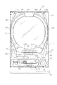
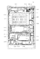
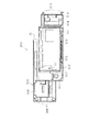
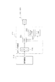
以下、遊技機の一種であるパチンコ遊技機(以下、「パチンコ機」という)の一実施の形態を、図面に基づいて詳細に説明する。図1はパチンコ機10の正面図、図2はパチンコ機10の主要な構成を展開又は分解して示す斜視図、図3はパチンコ機10を構成する本体枠12の前面構成を示す正面図である。なお、図2、図3では便宜上、パチンコ機10の遊技領域内の構成を空白としている。
Hereinafter, an embodiment of a pachinko gaming machine (hereinafter referred to as “pachinko machine”), which is a type of gaming machine, will be described in detail with reference to the drawings. 1 is a front view of the pachinko machine 10, FIG. 2 is a perspective view showing an exploded or exploded main configuration of the pachinko machine 10, and FIG. 3 is a front view showing a front structure of a main body frame 12 constituting the pachinko machine 10. is there. In FIG. 2 and FIG. 3, the configuration in the game area of the pachinko machine 10 is left blank for convenience.
図1〜図3に示すように、パチンコ機10は、当該パチンコ機10の外殻を形成する外枠11を備えている。外枠11は、遊技ホールへの設置の際に、いわゆる島設備に取り付けられる。外枠11は、木製の板材を全体として矩形枠状に組み合わせた状態とされ、各板材を小ネジ等の離脱可能な締結部材により固定することによって構成されている。従って、釘やリベットを使って各板材を組み付けていた従来構造と比べて構成部材の再利用(リユース)が容易な構成となっている。本実施の形態では、外枠11の上下方向の外寸は809mm(内寸771mm)、左右方向の外寸は518mm(内寸480mm)となっている。なお、外枠11を合成樹脂やアルミニウム等の金属によって構成してもよい。
As shown in FIGS. 1 to 3, the pachinko machine 10 includes an outer frame 11 that forms an outer shell of the pachinko machine 10. The outer frame 11 is attached to a so-called island facility when installed in the game hall. The outer frame 11 is in a state in which wooden plate members are combined in a rectangular frame shape as a whole, and is configured by fixing each plate member with a detachable fastening member such as a small screw. Therefore, compared to the conventional structure in which the plate members are assembled using nails and rivets, the components can be easily reused. In the present embodiment, the outer dimension of the outer frame 11 is 809 mm (inner dimension 771 mm), and the outer dimension in the left and right direction is 518 mm (inner dimension 480 mm). In addition, you may comprise the outer frame 11 with metals, such as a synthetic resin and aluminum.
外枠11の一側部には、本体枠12が開閉可能に支持されている。その開閉軸線はパチンコ機10の正面からみて左側に上下へ延びるように設定されており、その開閉軸線を軸心にして本体枠12が前方側に開放できるようになっている。更に言うと、本パチンコ機10には右側に遊技球発射ハンドル18の設置箇所が設けられているため、遊技球発射ハンドル18とは反対側の側部を中心に本体枠12を開閉可能としたということができる。本体枠12は合成樹脂、具体的にはABS樹脂により構成されている。ABS樹脂を用いることにより、比較的低コストで耐衝撃性の高い本体枠12を得ることができる。本体枠12をアルミニウム等の金属によって構成してもよい。なお本実施の形態では、外枠11と本体枠12とにより遊技機本体が構成されている。外枠11に代わる構成として設置枠体を遊技ホール側に予め設けておき、遊技ホールへのパチンコ機10の設置に際しては本体枠12を前記設置枠体に組み付ける構成とすることも可能である。かかる構成では、本体枠12とにより遊技機本体が構成される。
A body frame 12 is supported at one side of the outer frame 11 so as to be openable and closable. The opening / closing axis is set to extend vertically to the left as viewed from the front of the pachinko machine 10, and the main body frame 12 can be opened forward with the opening / closing axis serving as the axis. Furthermore, since the pachinko machine 10 is provided with a game ball launching handle 18 on the right side, the main body frame 12 can be opened and closed around the side opposite to the game ball launching handle 18. It can be said. The main body frame 12 is made of synthetic resin, specifically ABS resin. By using the ABS resin, the main body frame 12 having a relatively low cost and high impact resistance can be obtained. The body frame 12 may be made of a metal such as aluminum. In the present embodiment, the outer frame 11 and the main body frame 12 constitute a gaming machine main body. As an alternative to the outer frame 11, an installation frame may be provided in advance on the game hall side, and the main body frame 12 may be assembled to the installation frame when the pachinko machine 10 is installed in the game hall. In such a configuration, the main body frame 12 constitutes a gaming machine main body.
本体枠12の前面側の下部位置には、前面板14が設けられている。前面板14は横長状に形成され、その横幅は本体枠12の横幅とほぼ一致するように構成されている。前面板14は、幅方向ほぼ中央部において手前側へ膨出した膨出部15aを有するベース部15と、ベース部15の膨出部15a内側に設けられ下方にくぼんだ皿形状をなす球受皿としての下皿16と、下皿16の奥側の壁面を構成する奥壁パネル17とを備えている。ベース部15は本体枠12に対してネジ等の締結部材により固定されていることから、ベース部15が本体枠12に対する取付部を構成している。ベース部15には膨出部15aよりも右方に、手前側へ突出するようにして遊技球発射ハンドル18が設けられている。奥壁パネル17には球排出口17aが設けられており、球排出口17aより排出された遊技球が下皿16内に貯留されるようになっている。
A front plate 14 is provided at a lower position on the front side of the main body frame 12. The front plate 14 is formed in a horizontally long shape, and the width thereof is configured to substantially match the width of the main body frame 12. The front plate 14 includes a base portion 15 having a bulging portion 15a that bulges to the near side in a substantially central portion in the width direction, and a ball tray that is provided inside the bulging portion 15a of the base portion 15 and has a dish shape recessed downward. And a back wall panel 17 constituting a wall on the back side of the bottom plate 16. Since the base portion 15 is fixed to the main body frame 12 by a fastening member such as a screw, the base portion 15 constitutes an attachment portion for the main body frame 12. A game ball launching handle 18 is provided on the base portion 15 so as to protrude to the right side of the bulging portion 15a. The back wall panel 17 is provided with a ball discharge port 17 a so that the game balls discharged from the ball discharge port 17 a are stored in the lower plate 16.
ベース部15の膨出部15a前面側にはスライド式の球抜きレバー19が設けられている。なお、球抜きレバー19はプッシュ式としてもよい。そして、球抜きレバー19が操作されると下皿16の底面に設けられた図示しない閉鎖板が一体に又はリンクを介して移動して球抜き穴が開放され、下皿16内の貯留球が下方に排出されるよう構成されている。球抜きレバー19には球抜き穴を塞ぐ側へ球抜きレバー19を付勢するコイルバネ等の付勢部材が設けられ、球抜きレバー19の操作が解除された際には付勢部材の付勢力によって閉鎖板が球抜き穴の開放位置に復帰する構成となっている。奥壁パネル17の球排出口17aとは異なる位置には、多数の小孔が集合したスピーカカバー部17bが形成されており、当該パネル17の後方に設置されたスピーカ20の出力音がスピーカカバー部17bを通じて前方に発せられるようになっている。
A slide-type ball removal lever 19 is provided on the front side of the bulging portion 15 a of the base portion 15. The ball removal lever 19 may be a push type. When the ball removal lever 19 is operated, a closing plate (not shown) provided on the bottom surface of the lower plate 16 moves integrally or via a link to open the ball removal hole, and the stored balls in the lower plate 16 are moved. It is configured to be discharged downward. The ball removal lever 19 is provided with a biasing member such as a coil spring that biases the ball removal lever 19 toward the side where the ball removal hole is closed, and the biasing force of the biasing member when the operation of the ball removal lever 19 is released. Thus, the closing plate returns to the opening position of the ball hole. A speaker cover portion 17b in which a large number of small holes are gathered is formed at a position different from the ball discharge port 17a of the back wall panel 17, and the output sound of the speaker 20 installed behind the panel 17 is the speaker cover. It is emitted forward through the portion 17b.
本体枠12の前面側の前面板14を除く範囲には、本体枠12を覆うようにして前面扉としての前扉枠13が設けられている。従って、前面板14と前扉枠13とにより本体枠12の前面側全体が覆われている。前扉枠13は、本体枠12に対して開閉可能に取り付けられており、本体枠12と同様、パチンコ機10の正面からみて左側に上下に延びる開閉軸線を軸心にして前方側に開放できるようになっている。なお、前扉枠13は前面板14と同様、ABS樹脂にて成形されている。前扉枠13はパチンコ機10の前面側に露出されるが、ABS樹脂で成形していることによって、装飾等の目的で表面の適宜箇所にメッキを施すことが可能となる。
A front door frame 13 as a front door is provided in a range excluding the front plate 14 on the front side of the main body frame 12 so as to cover the main body frame 12. Accordingly, the entire front side of the main body frame 12 is covered by the front plate 14 and the front door frame 13. The front door frame 13 is attached to the main body frame 12 so as to be openable and closable. Like the main body frame 12, the front door frame 13 can be opened forward with an opening / closing axis extending vertically to the left when viewed from the front of the pachinko machine 10. It is like that. The front door frame 13 is formed of ABS resin, like the front plate 14. The front door frame 13 is exposed on the front side of the pachinko machine 10, but by molding with ABS resin, it is possible to apply plating to appropriate portions of the surface for the purpose of decoration or the like.
前扉枠13の下部位置には、下皿16の上方において手前側へ膨出した膨出部22が設けられ、その膨出部22内側には上方に開口した上皿23が設けられている。上皿23は、後述する払出装置より払い出された遊技球を一旦貯留し、一列に整列させながら遊技球発射装置側へ導くための球受皿である。膨出部22前面側には上皿23用の球抜きレバー24が設けられており、この球抜きレバー24を操作すると上皿23の最下流部付近に設けられた球抜き通路(図示略)が開放され、上皿23内の貯留球が下皿16へ排出されるようになっている。なお、上皿23も下皿16等と同様、難燃性のABS樹脂にて構成することが可能である。
A lower portion of the front door frame 13 is provided with a bulging portion 22 that bulges to the near side above the lower plate 16, and an upper plate 23 that opens upward is provided inside the bulging portion 22. . The upper plate 23 is a ball receiving tray for temporarily storing game balls paid out from a payout device, which will be described later, and guiding them to the game ball launching device side while aligning them in a row. A ball removal lever 24 for the upper plate 23 is provided on the front surface side of the bulging portion 22, and when this ball removal lever 24 is operated, a ball removal passage (not shown) provided near the most downstream portion of the upper plate 23. Is opened, and the stored balls in the upper plate 23 are discharged to the lower plate 16. In addition, the upper plate 23 can also be comprised with a flame-retardant ABS resin similarly to the lower plate 16 grade | etc.,.
本パチンコ機10では、ガラス扉枠と前飾り枠とを個別に設けこれらを前面枠(本実施の形態の本体枠に相当)に対して各々開閉可能とすると共に前飾り枠に上皿を設けていた従来構成と異なり、ガラス扉枠と前飾り枠とを1つに統合して前扉枠13とし、前扉枠13に対して一体的に上皿23を設ける構成としている。この場合、ガラス扉枠と前飾り枠とを1つに統合して前扉枠13としたため、当該前扉枠13においてガラス支持構造の強度向上が実現できる。つまり、本パチンコ機10では、遊技領域の拡張を目的とし、その遊技領域拡張に伴い大きめのガラス137を前扉枠13に搭載している。従って、ガラス周囲の枠部分が幅狭になり、強度低下の問題が懸念されるが、ガラス下方に上皿一体の枠部分を設けること等によりガラス支持構造の十分な強度が確保できる。
In the pachinko machine 10, a glass door frame and a front decoration frame are individually provided, and these can be opened and closed with respect to the front frame (corresponding to the main body frame of the present embodiment), and an upper plate is provided on the front decoration frame. Unlike the conventional configuration, the glass door frame and the front decoration frame are integrated into a front door frame 13, and the upper plate 23 is provided integrally with the front door frame 13. In this case, since the glass door frame and the front decoration frame are integrated into the front door frame 13, the strength of the glass support structure can be improved in the front door frame 13. That is, in this pachinko machine 10, for the purpose of expanding the game area, a large glass 137 is mounted on the front door frame 13 along with the expansion of the game area. Therefore, although the frame portion around the glass becomes narrow and there is a concern about the problem of strength reduction, sufficient strength of the glass support structure can be ensured by providing a frame portion integrated with the upper plate below the glass.
図3に示すように、本体枠12は、外形が前記外枠11とほぼ同一形状をなす樹脂ベース25を主体に構成されており、樹脂ベース25の中央部には略円形状の窓孔26が形成されている。樹脂ベース25の後側には遊技盤ユニット30が着脱可能に装着されている。
As shown in FIG. 3, the main body frame 12 is mainly composed of a resin base 25 whose outer shape is substantially the same as that of the outer frame 11, and a substantially circular window hole 26 is formed at the center of the resin base 25. Is formed. A game board unit 30 is detachably mounted on the rear side of the resin base 25.
遊技盤ユニット30には、前後方向に貫通する大小複数の貫通孔が形成されている。各貫通孔には一般入賞口31、可変入賞装置32、作動口33、スルーゲート34及び可変表示ユニット35等がそれぞれ設けられている(図4参照)。実際には、一般入賞口31、可変入賞装置32、作動口33、スルーゲート34及び可変表示ユニット35はねじ等により遊技盤ユニット30の表面に取り付けられている。本実施の形態では、可変表示ユニット35が遊技盤ユニット30の略中央に配置され、その下方に作動口33が配置され、さらにその下方に可変入賞装置32が配置されている。
The game board unit 30 is formed with a plurality of large and small through holes penetrating in the front-rear direction. Each through hole is provided with a general winning port 31, a variable winning device 32, an operating port 33, a through gate 34, a variable display unit 35, and the like (see FIG. 4). Actually, the general winning port 31, the variable winning device 32, the operating port 33, the through gate 34, and the variable display unit 35 are attached to the surface of the game board unit 30 by screws or the like. In the present embodiment, the variable display unit 35 is disposed substantially at the center of the game board unit 30, the operation port 33 is disposed below the variable display unit 35, and the variable winning device 32 is disposed further below.
可変表示ユニット35の左右両側にスルーゲート34が配置され、遊技盤ユニット30の下部両側に一般入賞口31がそれぞれ複数配置されている。作動口33には、所定の条件下で作動状態(開放状態)となる電動役物が付随的に設けられている。前記一般入賞口31、可変入賞装置32及び作動口33に遊技球が入ると、それが後述する検出スイッチにより検出され、その検出結果に基づいて上皿23(場合によっては下皿16)に対し所定数の賞品球が払い出される。
Through gates 34 are disposed on both the left and right sides of the variable display unit 35, and a plurality of general winning holes 31 are disposed on both lower sides of the game board unit 30. The operating port 33 is additionally provided with an electric accessory that is activated (opened) under a predetermined condition. When a game ball enters the general winning port 31, the variable winning device 32, and the operating port 33, it is detected by a detection switch described later, and based on the detection result, the upper plate 23 (in some cases, the lower plate 16) is detected. A predetermined number of prize balls are paid out.
その他に、可変表示装置32の下部であって遊技盤ユニット30の下端から上方に離間した位置にはアウト口36が設けられており、各種入賞口等に入らなかった遊技球はアウト口36を通って図示しない球排出路の方へと案内されるようになっている。また、遊技盤ユニット30には、遊技球の落下方向を適宜分散、調整等するために多数の釘39が植設されていると共に、風車37等の各種部材(役物)が配設されている。
In addition, an out port 36 is provided at a position below the variable display device 32 and spaced upward from the lower end of the game board unit 30. It is guided through a ball discharge path (not shown). In addition, the game board unit 30 is provided with a large number of nails 39 for dispersing and adjusting the falling direction of the game balls as appropriate, and various members (functions) such as a windmill 37 are provided. Yes.
遊技盤ユニット30の左右両側部には、組付相手である本体枠12の左右両側からの張出領域との干渉を回避するように凹部としての切欠38が複数箇所に形成されている。
On the left and right sides of the game board unit 30, notches 38 as recesses are formed at a plurality of locations so as to avoid interference with the projecting regions from the left and right sides of the body frame 12 that is the assembly partner.
遊技盤ユニット30の表面に配設される可変表示ユニット35には、作動口33への入賞をトリガとして第1図柄(特別図柄)を変動表示する図柄表示装置41が設けられている。可変表示ユニット35には、図柄表示装置41を囲むようにしてセンターフレーム43が配設されている。このセンターフレーム43は、その上部がパチンコ機10前方に延出している。これにより、図柄表示装置41の表示画面の前方を遊技球が落下していくのが防止されており、遊技球の落下により表示画面の視認性が低下するといった不都合が生じない構成となっている。センターフレーム43の上部中央には、第1特定ランプ部47及び第2特定ランプ部48が横並びの状態で設けられている。また、これら両特定ランプ部47,48が配設された領域を挟むように、第1特定ランプ部47及び図柄表示装置41に対応した保留ランプ44が設けられている。遊技球が作動口33を通過した回数は最大4回まで保留され、保留ランプ44の点灯によってその保留個数が表示されるようになっている。なお、保留ランプ44は、図柄表示装置41の一部で変動表示される構成等であっても良い。上述したように、センターフレーム43の上部がパチンコ機10前方に延出していることにより、保留ランプ44、第1特定ランプ部47及び第2特定ランプ部48の視認性が遊技球の落下により阻害されない構成となっている。センターフレーム43の下部には、第2特定ランプ部48に対応した保留ランプ46が設けられている。遊技球がスルーゲート34を通過した回数は最大4回まで保留され、保留ランプ46の点灯によってその保留個数が表示されるようになっている。なお、保留ランプ46は、前記保留ランプ44と同様に、図柄表示装置41の一部で変動表示される構成等であっても良い。
The variable display unit 35 disposed on the surface of the game board unit 30 is provided with a symbol display device 41 that variably displays the first symbol (special symbol) with a winning at the operation port 33 as a trigger. A center frame 43 is disposed in the variable display unit 35 so as to surround the symbol display device 41. The center frame 43 has an upper portion extending forward of the pachinko machine 10. As a result, the game ball is prevented from dropping in front of the display screen of the symbol display device 41, and the inconvenience that the visibility of the display screen is lowered due to the fall of the game ball does not occur. . In the upper center of the center frame 43, a first specific lamp portion 47 and a second specific lamp portion 48 are provided side by side. In addition, a holding lamp 44 corresponding to the first specific lamp section 47 and the symbol display device 41 is provided so as to sandwich the area where both the specific lamp sections 47 and 48 are disposed. The number of times that the game ball has passed through the operating port 33 is held up to a maximum of 4 times, and the holding number is displayed by turning on the holding lamp 44. Note that the hold lamp 44 may be configured to be variably displayed on a part of the symbol display device 41. As described above, since the upper part of the center frame 43 extends forward of the pachinko machine 10, the visibility of the holding lamp 44, the first specific lamp unit 47, and the second specific lamp unit 48 is hindered by the fall of the game ball. It is the composition which is not done. A holding lamp 46 corresponding to the second specific lamp portion 48 is provided below the center frame 43. The number of times that the game ball has passed through the through gate 34 is held up to a maximum of 4 times, and the holding number is displayed by turning on the holding lamp 46. Note that the hold lamp 46 may be configured to be variably displayed on a part of the symbol display device 41, similarly to the hold lamp 44.
図柄表示装置41は液晶ディスプレイを備えた液晶表示装置として構成されており、後述する表示制御装置により表示内容が制御される。図柄表示装置41には、例えば左、中及び右に並べて第1図柄が表示され、これらの図柄が上下方向にスクロールされるようにして変動表示されるようになっている。そして、予め設定されている有効ライン上に所定の組合せの図柄が停止表示された場合には、特別遊技状態(以下、大当たりという)が発生することとなる。この図柄の変動表示については、後に詳細に説明することとする。なお、図柄表示装置41は、8インチ以外の10インチ,7インチ等の液晶ディスプレイを備えたもの、ワイドサイズのディスプレイを備えたもの、又はCRT,ドットマトリックス,7セグメント等その他のタイプにより表示画面を構成したものであってもよい。
The symbol display device 41 is configured as a liquid crystal display device including a liquid crystal display, and the display content is controlled by a display control device described later. On the symbol display device 41, for example, the first symbols are displayed side by side on the left, middle, and right, and these symbols are variably displayed as they are scrolled up and down. When a predetermined combination of symbols is stopped and displayed on a preset active line, a special gaming state (hereinafter referred to as a jackpot) occurs. The symbol variation display will be described in detail later. In addition, the symbol display device 41 has a display screen according to another type such as a CRT, a dot matrix, a 7-segment display, or the like provided with a liquid crystal display of 10 inches or 7 inches other than 8 inches, a wide size display. It may be configured.
第1特定ランプ部47には、その内側に赤、緑、青の3色発光タイプのLEDランプが配設されている。そして、作動口33への入賞をトリガとして、所定の順序で発光色の切り替えが行われる。具体的には、作動口33への入賞をトリガとして、赤色光が点灯され、その状態で所定時間が経過すると緑色光に発光色が切り替えられる。そして、緑色光が点灯された状態で前記所定時間が経過すると青色光に発光色が切り替えられる。その後、発光色の切り替え停止時期がくるまで、赤色、緑色、青色という順序で発光色の切り替えが繰り返し行われる。これにより、第1特定ランプ部47には、赤色、緑色、青色が、この順序で繰り返し表示されることとなる。そして、最終的に赤色又は緑色が停止表示された場合には、大当たりが発生し、青色が停止表示された場合には、大当たりが発生しない。また、最終的に赤色で停止表示された場合と、最終的に緑色で停止表示された場合とで、大当たりの種類が異なり、前者の方が遊技者に有利な大当たりが発生することとなる。この発光色の切り替えに関しては、後に詳細に説明することとする。
The first specific lamp unit 47 is provided with a red, green, and blue three-color emission type LED lamp. Then, the emission color is switched in a predetermined order using a winning at the operation port 33 as a trigger. Specifically, red light is turned on with a winning at the operation port 33 as a trigger, and the emission color is switched to green light when a predetermined time elapses in this state. Then, when the predetermined time elapses with the green light turned on, the emission color is switched to blue light. Thereafter, the emission color is repeatedly switched in the order of red, green, and blue until the emission color switching stop time comes. Accordingly, red, green, and blue are repeatedly displayed in this order on the first specific lamp unit 47. And finally, when red or green is stopped and displayed, a big hit is generated, and when blue is stopped and displayed, no big win is generated. In addition, the type of jackpot is different between the case where the stop is finally displayed in red and the case where the stop is finally displayed in green, and the former has a jackpot that is more advantageous to the player. The switching of the emission color will be described in detail later.
一方、第2特定ランプ部48には、その内側に赤、緑の2色発光タイプのLEDランプが配設されている。この第2特定ランプ部48は、スルーゲート34の通過をトリガとして、所定の順序で発光色の切り替えが行われる。具体的には、遊技球がスルーゲート34を通過すると、赤色光の点灯と緑色光の点灯とが交互に行われる。これにより、第2特定ランプ部48には、赤色、緑色が交互に表示されることとなる。そして、赤色が停止表示された場合には、作動口33に付随する電動役物が所定時間だけ開放状態となるよう構成されている。
On the other hand, the second specific lamp portion 48 is provided with a red and green two-color light emitting type LED lamp inside thereof. In the second specific lamp unit 48, the emission color is switched in a predetermined order with the passage of the through gate 34 as a trigger. Specifically, when the game ball passes through the through gate 34, lighting of red light and lighting of green light are alternately performed. Thus, red and green are alternately displayed on the second specific lamp unit 48. And when red is stopped and displayed, it is comprised so that the electrically-driven accessory which accompanies the operating port 33 will be in an open state only for the predetermined time.
可変入賞装置32は、通常は遊技球が入賞できない又は入賞し難い閉状態になっており、大当たりの際に遊技球が入賞しやすい所定の開放状態に切り替えられるようになっている。より詳しくは、大当たりが発生すると、可変入賞装置32が所定の開放状態となり、遊技球が入賞し易い状態となる。可変入賞装置32の開放態様としては、所定時間(例えば30秒間)の経過又は所定個数(例えば10個)の入賞を1ラウンドとして、可変入賞装置32内の継続入賞口への入賞を条件として次ラウンドへの移行条件成立とし、複数ラウンド(例えば15ラウンド)を上限として可変入賞装置32が繰り返し開放されるものが一般的である。
The variable winning device 32 is normally in a closed state in which a game ball cannot be won or difficult to win, and is switched to a predetermined open state in which a game ball is easy to win in the case of a big win. More specifically, when the jackpot is generated, the variable winning device 32 is in a predetermined open state, and the game ball is easily won. As an opening mode of the variable prize winning device 32, a predetermined time (for example, 30 seconds) or a predetermined number (for example, ten) of winnings is defined as one round, and the following is performed on condition that a winning is made to a continuous prize opening in the variable prize winning device 32. In general, it is assumed that the condition for shifting to a round is satisfied, and the variable prize-winning device 32 is repeatedly opened up to a maximum of a plurality of rounds (for example, 15 rounds).
遊技盤ユニット30の表面には、遊技球発射装置から発射された遊技球を遊技盤ユニット30の表面上部へ案内するためのレール部材としてのレールユニット50が取り付けられており、遊技球発射ハンドル18の回動操作に伴い発射された遊技球はレールユニット50を通じて所定の遊技領域に案内されるようになっている。レールユニット50はリング状をなす樹脂成型品にて構成されており、より具体的には、摩擦抵抗を低減するべくフッ素配合のポリカーボネート樹脂が用いられている。レールユニット50は、内外二重に設けられた内レール部51と外レール部52とを有する。内レール部51は上方の約1/4ほどを除いて略円環状に形成され、外レール部52は内レール部51の上方開放領域を囲むようにかつ内レール51の左側部と並行するように略半円環状に形成されている。
On the surface of the game board unit 30, a rail unit 50 is attached as a rail member for guiding the game ball launched from the game ball launching device to the upper surface of the game board unit 30. The game balls fired in accordance with the turning operation are guided to a predetermined game area through the rail unit 50. The rail unit 50 is formed of a resin molded product having a ring shape, and more specifically, a fluorine-containing polycarbonate resin is used to reduce frictional resistance. The rail unit 50 includes an inner rail portion 51 and an outer rail portion 52 that are provided in an inner and outer double. The inner rail portion 51 is formed in a substantially annular shape except for about 1/4 of the upper portion, and the outer rail portion 52 surrounds the upper open area of the inner rail portion 51 and is parallel to the left side portion of the inner rail 51. Are formed in a substantially semi-annular shape.
内レール部51は、他の樹脂部分と一体成型され、遊技盤ユニット30の表面の面上にほぼ垂直に起立して設けられている。また、外レール部52は、内レール部51と同様に他の樹脂部分と一体成型され、遊技盤ユニット30の表面の面上にほぼ垂直に起立して設けられた支持部52aを有し、その支持部52aの内側面に、遊技球の飛翔をより滑らかなものとするための摺動プレート52bが取り付けられている。摺動プレート52bは、長尺状をなすステンレス製の金属帯よりなり、複数箇所で支持部52aに支持されている。かかる場合、内レール部51と外レール部52とにより誘導レールが構成され、これら各レール部51,52が所定間隔を隔てて対向する部分により球案内通路が形成されている。なお、内外のレール部51,52が対向する部位では、遊技盤ユニット30の表面との当接部53により各レール部51,52が連結されており、球案内通路は手前側に開放した溝状に形成されている。
The inner rail portion 51 is integrally formed with the other resin portions, and is provided to stand substantially vertically on the surface of the game board unit 30. Further, the outer rail portion 52 has a support portion 52a that is integrally molded with other resin portions in the same manner as the inner rail portion 51, and is provided to stand substantially vertically on the surface of the game board unit 30. A sliding plate 52b for smoothening the flight of the game ball is attached to the inner surface of the support portion 52a. The sliding plate 52b is made of a long metal strip made of stainless steel, and is supported by the support portion 52a at a plurality of locations. In such a case, a guide rail is constituted by the inner rail portion 51 and the outer rail portion 52, and a ball guide passage is formed by a portion where these rail portions 51 and 52 face each other with a predetermined interval. In addition, in the site | part which the inner and outer rail parts 51 and 52 oppose, each rail part 51 and 52 is connected by the contact part 53 with the surface of the game board unit 30, and a ball | bowl guide path is a groove | channel opened to the near side. It is formed in a shape.
レールユニット50において、前記球案内通路より遊技球が飛び出す部位(図4の左上部)には戻り球防止部材54が取着され、該飛び出した遊技球の最大飛翔部分に対応する部位(図4の右上部)には返しゴム55が取着されている。戻り球防止部材54により、一旦球案内通路から遊技盤ユニット30の表面の上部へと飛び出した遊技球が球案内通路内に戻ってしまうといった事態が防止される。また、所定以上の勢いで発射された遊技球は返しゴム55に当たり、遊技領域の中央寄りに跳ね返されるようになっている。
In the rail unit 50, a return ball prevention member 54 is attached to a portion (the upper left portion in FIG. 4) from which the game ball jumps out of the ball guide passage, and a portion corresponding to the maximum flight portion of the jumped game ball (FIG. 4). In the upper right part), a return rubber 55 is attached. The return ball preventing member 54 prevents a situation in which a game ball that has once jumped from the ball guide path to the upper portion of the surface of the game board unit 30 returns to the ball guide path. In addition, the game ball launched at a predetermined momentum or more hits the return rubber 55 and is rebounded toward the center of the game area.
レールユニット50の外周部には、外方へ張り出した円弧状のフランジ56が形成されている。フランジ56は、遊技盤ユニット30の表面に対する取付面を構成する。レールユニット50が遊技盤ユニット30の表面に取り付けられる際には、遊技盤ユニット30の表面上にフランジ56が当接され、その状態で、当該フランジ56に形成された複数の透孔にネジ等が挿通されて遊技盤ユニット30の表面に対するレールユニット50の締結がなされる。ここで、レールユニット50の上下及び左右の各端部は略直線状に形成されている。つまり、レールユニット50の上下及び左右の各端部においてはフランジ56が切り落とされ、パチンコ機10における有限の領域にてレール径の拡張、すなわち遊技盤ユニット30の表面上の遊技領域の拡張が図られるようになっている。レールユニット50は、遊技領域の最大幅となる位置が遊技盤ユニット30の左右端位置に至るように配設されている。なお、レールユニット50の球案内通路に対応する部位のなかでも特に遊技球の受け入れ部位に関しては、当該レールユニット50を強固に取り付けて遊技球の飛びを安定させるべく、該当するフランジ56が他よりも多い箇所(本実施の形態では3カ所、他は2カ所)でネジ止めされている。
An arc-shaped flange 56 projecting outward is formed on the outer periphery of the rail unit 50. The flange 56 constitutes a mounting surface for the surface of the game board unit 30. When the rail unit 50 is attached to the surface of the game board unit 30, the flange 56 is brought into contact with the surface of the game board unit 30, and in this state, screws or the like are inserted into the plurality of through holes formed in the flange 56. Is inserted and the rail unit 50 is fastened to the surface of the game board unit 30. Here, the upper and lower and left and right ends of the rail unit 50 are formed in a substantially linear shape. That is, the flange 56 is cut off at the upper and lower and left and right ends of the rail unit 50, and the rail diameter is expanded in a limited area in the pachinko machine 10, that is, the game area on the surface of the game board unit 30 is expanded. It is supposed to be. The rail unit 50 is arranged so that the position where the gaming area has the maximum width reaches the left and right end positions of the gaming board unit 30. Among the parts corresponding to the ball guide passages of the rail unit 50, particularly with respect to the game ball receiving part, the corresponding flange 56 is provided from others in order to firmly attach the rail unit 50 and stabilize the flight of the game ball. There are also many screws (three in this embodiment, two in the other).
内レール部51及び外レール部52間の球案内通路の入口には、同球案内通路の一部を閉鎖するようにして凸部57が形成されている。凸部57は、内レール部51の外周部から下方へ延びるように形成され、遊技領域まで至らず球案内通路内を逆流してくるファール球をファール球通路76(図3参照)に導く機能を有する。
A convex portion 57 is formed at the entrance of the ball guide passage between the inner rail portion 51 and the outer rail portion 52 so as to close a part of the ball guide passage. The convex portion 57 is formed so as to extend downward from the outer peripheral portion of the inner rail portion 51, and has a function of guiding a foul ball that does not reach the game area and flows backward in the ball guide passage to the foul ball passage 76 (see FIG. 3). Have
遊技盤ユニット30の表面においてレールユニット50よりも外方の左上部には、前後に貫通した中継端子孔59が設けられており、この中継端子孔59を通じて、遊技盤ユニット30の裏面に設置した中継端子板の接続コネクタ60がパチンコ機10前面側に露出されるようになっている。
A relay terminal hole 59 penetrating in the front-rear direction is provided in the upper left portion outside the rail unit 50 on the surface of the game board unit 30. The relay terminal hole 59 is installed on the back surface of the game board unit 30 through the relay terminal hole 59. The connection connector 60 of the relay terminal plate is exposed to the front side of the pachinko machine 10.
次に、遊技領域について説明する。遊技盤ユニット30の表面はレールユニット50(内外レール部51,52)により内外領域に区画され、略円形状に区画された内側領域が遊技領域とされている。
Next, the game area will be described. The surface of the game board unit 30 is partitioned into inner and outer regions by rail units 50 (inner and outer rail portions 51 and 52), and an inner region partitioned into a substantially circular shape is a game region.
本実施の形態では、遊技領域を、パチンコ機10の正面から見て内レール部51及び外レール部52によって囲まれる領域のうち、内外レール部51,52の対向部分である球案内通路の領域を除いた領域として説明する。つまり、遊技領域は球案内通路部分は含まないため、遊技領域の向かって左側限界位置は外レール部52によってではなく内レール部51によって特定される。また、遊技領域の向かって右側限界位置は内レール部51によって特定され、遊技領域の下側限界位置はアウト口36が形成された遊技盤ユニット30の下端位置によって特定され、遊技領域の上側限界位置は外レール部52によって特定される。
In the present embodiment, the game area is an area of a ball guide passage that is an opposite part of the inner and outer rail parts 51 and 52 among the areas surrounded by the inner rail part 51 and the outer rail part 52 when viewed from the front of the pachinko machine 10. It demonstrates as an area | region remove | excluding. That is, since the game area does not include the ball guide passage portion, the left limit position toward the game area is specified by the inner rail portion 51 instead of the outer rail portion 52. Further, the right limit position toward the game area is specified by the inner rail portion 51, the lower limit position of the game area is specified by the lower end position of the game board unit 30 in which the out port 36 is formed, and the upper limit of the game area is determined. The position is specified by the outer rail portion 52.
図3の説明に戻り、前記樹脂ベース25において、窓孔26(遊技盤ユニット30)の下方には、遊技球発射装置より発射された直後に遊技球を案内するための発射レール61が取り付けられている。発射レール61は、その後方の金属板62を介して樹脂ベース25に取付固定されており、所定の発射角度(打ち出し角度)にて直線的に延びるよう構成されている。従って、遊技球発射ハンドル18の回動操作に伴い発射された遊技球は、まずは発射レール61に沿って斜め上方に打ち出され、その後球案内通路を通じて遊技領域に案内される。
Returning to the description of FIG. 3, in the resin base 25, below the window hole 26 (game board unit 30), a launch rail 61 for guiding the game ball immediately after being launched from the game ball launcher is attached. ing. The firing rail 61 is fixedly attached to the resin base 25 via a metal plate 62 behind the firing rail 61, and is configured to extend linearly at a predetermined firing angle (launch angle). Accordingly, the game ball launched in accordance with the turning operation of the game ball launch handle 18 is first launched obliquely upward along the launch rail 61 and then guided to the game area through the ball guide path.
発射レール61と球案内通路との間には所定間隔の隙間があり、この隙間より下方にファール球通路76が設けられている。従って、仮に遊技球発射装置から発射された遊技球が戻り球防止部材54まで至らずファール球として球案内通路内を逆戻りする場合には、そのファール球がファール球通路76を介して下皿16に排出される。
There is a predetermined gap between the firing rail 61 and the ball guide passage, and a foul ball passage 76 is provided below the gap. Accordingly, if the game ball launched from the game ball launching device does not reach the return ball prevention member 54 and returns as a foul ball in the ball guide passage, the foul ball passes through the foul ball passage 76 to the lower plate 16. To be discharged.
ファール球が球案内通路内を逆流してくる際、その多くは外レール部52に沿って流れ、外レール部52の下端部に到達した時点で下方に落下するが、一部のファール球は球案内通路内で暴れ、内レール部51側へ跳ね上がるものもある。この際、跳ね上がったファール球は、球案内通路入口の前記凸部57に当たり、ファール球通路76に誘導される。これにより、ファール球の全てがファール球通路76に確実に案内され、ファール球と次に発射される遊技球との干渉が抑制される。
When the foul balls flow backward in the ball guide passage, most of them flow along the outer rail portion 52 and fall downward when reaching the lower end portion of the outer rail portion 52. Some rampage in the ball guide passage and jump to the inner rail 51 side. At this time, the splashed foul ball hits the convex portion 57 at the entrance of the ball guide passage and is guided to the foul ball passage 76. Thereby, all of the foul balls are reliably guided to the foul ball passage 76, and interference between the foul balls and the game balls to be fired next is suppressed.
なお、詳しい図面の開示は省略するが、遊技球発射装置には、前扉枠13側の球出口(上皿23の最下流部より通じる球出口)から遊技球が1つずつ供給される。この際、発射レール61の発射基端部付近にはその右側と手前側にそれぞれガイド部材63,64を設置してあるため、前扉枠13側の球出口から供給される遊技球が常に所定の発射位置にセットされ、安定した発射動作が実現できる。
Although detailed disclosure of the drawings is omitted, one game ball is supplied to the game ball launching device one by one from the ball outlet on the front door frame 13 side (ball outlet leading from the most downstream portion of the upper plate 23). At this time, guide members 63 and 64 are installed on the right side and the near side of the firing base end portion of the firing rail 61, respectively, so that the game balls supplied from the ball outlet on the front door frame 13 side are always predetermined. A stable launching operation can be realized.
また、本体枠12の前面において発射レール61の左側には、左右一対の排出口66,67が形成されると共に、その前方に、排出口66,67より排出された遊技球を上皿23又は下皿16の何れかに案内するための遊技球案内ユニット70が取り付けられている。便宜上以下の説明では、排出口66を第1排出口、排出口67を第2排出口ともいう。これら排出口66,67は、本体枠12の背面に設けられた遊技球分配部245(図10参照)に通じており、基本的に第1排出口66より遊技球の排出が行われ、この第1排出口66も含め上皿23に通じる通路が遊技球で一杯になると、第1排出口66に代えて第2排出口67より遊技球の排出が行われるようになっている。
A pair of left and right discharge ports 66 and 67 are formed on the left side of the launch rail 61 on the front surface of the main body frame 12, and the game balls discharged from the discharge ports 66 and 67 are placed in front of the upper plate 23 or A game ball guide unit 70 for guiding one of the lower dishes 16 is attached. For convenience, in the following description, the discharge port 66 is also referred to as a first discharge port, and the discharge port 67 is also referred to as a second discharge port. These discharge ports 66 and 67 communicate with a game ball distribution unit 245 (see FIG. 10) provided on the back surface of the main body frame 12, and game balls are basically discharged from the first discharge port 66. When the passage leading to the upper plate 23 including the first outlet 66 is filled with game balls, the game balls are discharged from the second outlet 67 instead of the first outlet 66.
遊技球案内ユニット70は、ポリカーボネート樹脂等の透明な樹脂材料により内部を視認可能に構成され、本体枠12に対して前扉枠13を閉鎖した状態で本体枠12と前扉枠13との間に収まるよう厚みが比較的薄くなるように形成されている。遊技球案内ユニット70には、前述のファール球通路76が一体的に形成されている。遊技球案内ユニット70には、前記排出口66,67と下皿16とを連通するための球排出通路71が形成されている。遊技球案内ユニット70には、本体枠12の第1排出口66の手前側に、上皿23に連通する連通口72が形成され、連通口72を閉鎖するようにして開閉プレート73が取り付けられている。開閉プレート73は支軸74により回動可能に支持され、付勢手段としてのバネ75により連通口72を閉鎖する位置に常時付勢されている。
The game ball guide unit 70 is configured to be visible with a transparent resin material such as polycarbonate resin, and between the main body frame 12 and the front door frame 13 with the front door frame 13 closed with respect to the main body frame 12. It is formed so that the thickness is comparatively thin so that it can be accommodated. The game ball guide unit 70 is integrally formed with the foul ball passage 76 described above. The game ball guide unit 70 is formed with a ball discharge passage 71 for communicating the discharge ports 66 and 67 with the lower plate 16. In the game ball guide unit 70, a communication port 72 communicating with the upper plate 23 is formed on the front side of the first discharge port 66 of the main body frame 12, and an opening / closing plate 73 is attached so as to close the communication port 72. ing. The opening / closing plate 73 is rotatably supported by a support shaft 74 and is always urged to a position where the communication port 72 is closed by a spring 75 as urging means.
遊技球案内ユニット70の上記構成によれば、前扉枠13を開放した状態ではバネ75の付勢力により開閉プレート73が図示の如く起き上がり、連通口72を閉鎖する。この状態では、第1排出口66より排出される遊技球が球排出通路71を通じて下皿16に案内される。従って、連通口72の上流側に遊技球が貯留されている状態で前扉枠13を開放した場合、その貯留球は連通口72よりこぼれ落ちることなく、球排出通路71を通じて下皿16に流下する。つまり、前飾り枠が省略され前扉枠13に対して上皿23が直接設けられる構成とした本パチンコ機10にあっても、前扉枠13の開放に際し連通口72の上流側にある遊技球がこぼれ落ちてしまうといった不都合が防止できる。これに対し、前扉枠13を閉鎖した状態では、前扉枠13の裏面に設けられた球通路樋138(図2参照)によりバネ75の付勢力に抗して開閉プレート73が押し開けられる。この状態では、第1排出口66より排出される遊技球が連通口72を介して上皿23に案内される。従って、連通口72より上流側の遊技球は上皿23に払い出される。なお、遊技球案内ユニット70の球排出通路71下流側には、下皿16に排出された遊技球が一杯(満タン)になったことを検知する下皿満タンスイッチが取り付けられている。
According to the above configuration of the game ball guide unit 70, the open / close plate 73 rises as shown in the figure by the urging force of the spring 75 when the front door frame 13 is opened, and the communication port 72 is closed. In this state, the game ball discharged from the first discharge port 66 is guided to the lower plate 16 through the ball discharge passage 71. Therefore, when the front door frame 13 is opened in a state where game balls are stored upstream of the communication port 72, the stored balls flow down to the lower plate 16 through the ball discharge passage 71 without spilling from the communication port 72. To do. In other words, even in the present pachinko machine 10 in which the front decorative frame is omitted and the upper plate 23 is directly provided on the front door frame 13, the game on the upstream side of the communication port 72 when the front door frame 13 is opened. The inconvenience of spilling a ball can be prevented. On the other hand, when the front door frame 13 is closed, the opening / closing plate 73 is pushed open against the biasing force of the spring 75 by a ball passage rod 138 (see FIG. 2) provided on the back surface of the front door frame 13. . In this state, the game ball discharged from the first discharge port 66 is guided to the upper plate 23 through the communication port 72. Accordingly, the game ball upstream of the communication port 72 is paid out to the upper plate 23. A lower plate full tank switch for detecting that the game ball discharged to the lower plate 16 is full (full tank) is attached to the downstream side of the ball discharge passage 71 of the game ball guide unit 70.
樹脂ベース25には、窓孔26の左上部にも小窓79が設けられている。この小窓79は、図4で説明した遊技盤ユニット30の中継端子孔59に対応する位置にそれとほぼ同一の形状で設けられ、中継端子孔59及び小窓79を通じて、遊技盤裏面に設置した中継端子板の接続コネクタ60が本体枠12の前面側に露出される。かかる構成において、前扉枠13側に設けた各種ランプに対しては、本体枠12(樹脂ベース25)の小窓79より露出した接続コネクタ60を介して電気的な接続がなされている。樹脂ベース25の上部には、前扉枠13の開放の状態を検出するための前扉枠開放スイッチ27が設けられている。前扉枠開放スイッチ27は、樹脂ベース25の前面に出没可能なピンを有しており、本体枠12に対して前扉枠13を閉じた状態ではピンが押し込まれて前扉枠13の閉鎖が検知され、本体枠12に対して前扉枠13を開いた状態ではピンが突出位置に戻って前扉枠13の開放が検知されるようになっている。樹脂ベース25の左右2カ所には、本体枠12に対して前扉枠13を閉じた際に前扉枠13背面の金具類(図5に示す補強板131〜134)に接触し、且つその金具類を本体枠12側に導通させてアース(接地)するための金属片28a,28bが取り付けられている。従って、金属片28a,28bを通じて、前扉枠13背面の金具類が本体枠12側の施錠装置やヒンジ金具に導通され、これら施錠装置やヒンジ金具と共にアースされる。
A small window 79 is also provided in the resin base 25 at the upper left portion of the window hole 26. The small window 79 is provided in the position corresponding to the relay terminal hole 59 of the game board unit 30 described with reference to FIG. The connection connector 60 of the relay terminal plate is exposed on the front side of the main body frame 12. In such a configuration, various lamps provided on the front door frame 13 side are electrically connected via the connection connector 60 exposed from the small window 79 of the main body frame 12 (resin base 25). A front door frame opening switch 27 for detecting the open state of the front door frame 13 is provided on the top of the resin base 25. The front door frame opening switch 27 has a pin that can be projected and retracted on the front surface of the resin base 25. When the front door frame 13 is closed with respect to the main body frame 12, the pin is pushed in and the front door frame 13 is closed. When the front door frame 13 is opened with respect to the main body frame 12, the pin returns to the protruding position and the opening of the front door frame 13 is detected. When the front door frame 13 is closed with respect to the main body frame 12, the resin base 25 comes into contact with metal fittings (reinforcing plates 131 to 134 shown in FIG. 5) on the back of the front door frame 13, and Metal pieces 28a and 28b are attached to connect the metal fittings to the main body frame 12 side for grounding. Therefore, the metal fittings on the back of the front door frame 13 are conducted to the locking device and the hinge fitting on the main body frame 12 side through the metal pieces 28a and 28b, and are grounded together with the locking device and the hinge fitting.
本体枠12の左端側(開閉軸線側)には、前扉枠13を開閉可能に支持するための支持機構として、上下一対の支持金具81,82が取り付けられている。上側の支持金具81には手前側に切欠を有する支持孔83が設けられ、下側の支持金具82には上方へ突出する突起軸84が設けられている。なお、支持金具81,82に支持される前扉枠13の具体的構成については後述する。また、本体枠12の右端側(開閉軸線とは反対側)には、前扉枠13裏面側の開放端側に設けた上下一対の鉤金具155,156(図2参照)を挿入するための挿入孔87,88がそれぞれ設けられている。本パチンコ機10では、本体枠12や前扉枠13を施錠状態とするための施錠装置が本体枠12の裏面側に隠れて配置される構成となっている。従って、鉤金具155,156が挿入孔87,88を介して施錠装置に係止されることによって、前扉枠13が本体枠12に対して開放不能に施錠される。
A pair of upper and lower support brackets 81 and 82 are attached to the left end side (opening / closing axis line side) of the main body frame 12 as a support mechanism for supporting the front door frame 13 so that it can be opened and closed. The upper support fitting 81 is provided with a support hole 83 having a notch on the front side, and the lower support fitting 82 is provided with a protruding shaft 84 protruding upward. The specific configuration of the front door frame 13 supported by the support fittings 81 and 82 will be described later. Further, a pair of upper and lower metal fittings 155 and 156 (see FIG. 2) provided on the open end side on the back side of the front door frame 13 is inserted into the right end side (the side opposite to the opening / closing axis) of the main body frame 12. Insertion holes 87 and 88 are provided, respectively. The pachinko machine 10 is configured such that a locking device for locking the main body frame 12 and the front door frame 13 is hidden behind the main body frame 12. Therefore, the front door frame 13 is locked to the main body frame 12 so that it cannot be opened by locking the metal fittings 155 and 156 to the locking device via the insertion holes 87 and 88.
本体枠12の右下隅部には、外枠11に対する本体枠12の施錠及び解錠、並びに本体枠12に対する前扉枠13の施錠及び解錠を行うための鍵部材としてのシリンダ錠91が設置されている。シリンダ錠91は施錠装置に一体化されており、施錠装置のうちシリンダ錠91だけが本体枠12の前方に突出した状態で設けられている。この場合、シリンダ錠91は、遊技領域の最大幅となる位置とは異なる位置に設けられている。シリンダ錠91は、本体枠12の施解錠と前扉枠13の施解錠とを共に賄う機能を有しており、鍵穴に差し込んだキーを左(反時計回り方向)に回すと本体枠12の施錠が解かれ、逆にキーを右(時計回り方向)に回すと前扉枠13の施錠が解かれるようになっている。
A cylinder lock 91 as a key member for locking and unlocking the main frame 12 with respect to the outer frame 11 and locking and unlocking the front door frame 13 with respect to the main frame 12 is installed at the lower right corner of the main frame 12. Has been. The cylinder lock 91 is integrated with the locking device, and only the cylinder lock 91 of the locking device is provided in a state of protruding in front of the main body frame 12. In this case, the cylinder lock 91 is provided at a position different from the position that is the maximum width of the game area. The cylinder lock 91 has a function to cover both the locking and unlocking of the main body frame 12 and the locking and unlocking of the front door frame 13, and when the key inserted into the key hole is turned counterclockwise (counterclockwise direction) When the key is unlocked and the key is turned to the right (clockwise direction), the front door frame 13 is unlocked.
図2に示すように、本体枠12には、シリンダ錠91を囲むようにして縦長状のカバー部材92が取り付けられている。詳細な図示は省略するが、カバー部材92には、その上端部及び下端部に係止部(フック)が形成されている。従って、上側の係止部を本体枠12側に係止させると共に、下側の係止部を本体枠12と前面板14との間に挟み込むことにより、カバー部材92が本体枠12に取り付けられる。前扉枠13には、カバー部材92の形状に合わせて切欠部145が形成されており、前扉枠13を閉鎖した状態ではこの前扉枠13と共にカバー部材92がパチンコ機前面部を構成する。なお、前扉枠13を閉鎖したとき、カバー部材92に形成された鍔部が前扉枠13により押さえられ、カバー部材92のがたつきが防止されるようになっている。
As shown in FIG. 2, a vertically long cover member 92 is attached to the main body frame 12 so as to surround the cylinder lock 91. Although detailed illustration is omitted, the cover member 92 has locking portions (hooks) formed at the upper end portion and the lower end portion thereof. Therefore, the cover member 92 is attached to the main body frame 12 by locking the upper locking portion to the main body frame 12 side and sandwiching the lower locking portion between the main body frame 12 and the front plate 14. . The front door frame 13 is formed with a notch 145 corresponding to the shape of the cover member 92. When the front door frame 13 is closed, the cover member 92 together with the front door frame 13 constitutes the front portion of the pachinko machine. . When the front door frame 13 is closed, the flange formed on the cover member 92 is pressed by the front door frame 13 to prevent the cover member 92 from rattling.
次に、前扉枠13について図1,図5を参照しつつ説明する。なお、図5は、前扉枠13の背面図である。
Next, the front door frame 13 will be described with reference to FIGS. FIG. 5 is a rear view of the front door frame 13.
前扉枠13には遊技領域のほぼ全域を前方から視認することができるようにした視認窓としての窓部101が形成されている。窓部101は、円形に近い略楕円形状をなし、より詳しくは、その左右側の略中央部が上下側に比べて緩やかに湾曲した形状となっている。なお、前記略中央部が直線状になる形状であってもよい。本実施の形態におけるフレーム幅寸法は、本体枠12において外レール部52の最上部(遊技領域の上端)と本体枠12の上端との間の距離とほぼ一致するものである。これにより、遊技領域における上部領域の視認性が確保されやすくなると共に、大型の可変表示ユニット35も比較的上方に配置することができるようになっている。
The front door frame 13 is formed with a window portion 101 as a viewing window so that almost the entire game area can be viewed from the front. The window portion 101 has a substantially oval shape that is nearly circular, and more specifically, a substantially central portion on the left and right sides of the window portion 101 is gently curved as compared to the upper and lower sides. The substantially central portion may have a linear shape. The frame width dimension in the present embodiment is substantially the same as the distance between the uppermost portion of the outer rail portion 52 (the upper end of the game area) and the upper end of the main body frame 12 in the main body frame 12. Thereby, the visibility of the upper area in the game area can be easily ensured, and the large variable display unit 35 can also be arranged relatively upward.
前扉枠13の左右のフレーム部分は、フレーム幅を小さくするには制約があり、前扉枠13自体の強度及びガラス支持強度を確保するのに十分な幅寸法を必要とする。この場合、前扉枠13を閉鎖した状態において、球案内通路の一部が、前扉枠13の左側フレーム部分と重複し覆い隠されるようになる。しかしながら、球案内通路において遊技球が一時的に視認困難となったとしても、かかる球案内通路は遊技球が遊技領域に案内されるまでの通過領域に過ぎず、遊技者が主として遊技を楽しむ遊技領域において遊技球が視認困難となるわけではない。そのため、実際の遊技に際しては何ら支障が生じない。以上により、前扉枠13の十分な強度及びガラス支持強度を確保しつつも、遊技に何ら支障を及ぼすことなく遊技領域の拡張が可能となる。
The left and right frame portions of the front door frame 13 are restricted in reducing the frame width, and need a sufficient width dimension to ensure the strength of the front door frame 13 itself and the glass support strength. In this case, in a state where the front door frame 13 is closed, a part of the spherical guide passage overlaps and is covered with the left frame portion of the front door frame 13. However, even if it becomes difficult to visually recognize the game ball in the ball guide passage, the ball guide passage is only a passing area until the game ball is guided to the game area, and the game where the player mainly enjoys the game. The game ball is not difficult to see in the area. Therefore, there is no trouble in actual game. As described above, it is possible to expand the game area without causing any trouble to the game, while ensuring sufficient strength and glass support strength of the front door frame 13.
前扉枠13にはその周囲(例えばコーナー部分)に各種ランプ等の発光手段が設けられている。これら発光手段は、大当たり時や所定のリーチ時等における遊技状態の変化に応じて点灯、点滅のように発光態様が変更制御されることにより、遊技中の演出効果を高める役割を果たす。例えば、窓部101の周縁に沿ってLED等の発光手段を内蔵した環状電飾部102が左右対称に設けられ、環状電飾部102の中央であってパチンコ機10の最上部にはLED等の発光手段を内蔵した中央電飾部103が設けられている。本パチンコ機10では、中央電飾部103が大当たりランプとして機能し、大当たり状態時に点灯や点滅を行うことにより大当たり中であることを報知する。また、上皿23周りにも、同じくLED等の発光手段を内蔵した上皿電飾部104が設けられている。その他、中央電飾部103の左右側方には、賞球払出中に点灯する賞球ランプ105と所定のエラー時に点灯するエラー表示ランプ106とがそれぞれ設けられている。なお、環状電飾部102は、内外二重の樹脂カバー層とその内側に収容された発射板付き発光体(LED)とよりなり、樹脂カバー層の各々の内側面には各層で縦横に交差する向きに突条(又は波状の突起)が設けられている。外側の樹脂カバー層は透明であり、内側の樹脂カバー層は有色である。従って、環状電飾部102を発光させれば、多数に分散化された状態、又は立体感を伴った状態の電飾が実現できるようになる。樹脂カバー層には、ガラス粉末入りの樹脂材料を用いると良い。このような樹脂カバー層の構成は、他の電飾部(例えば中央電飾部103や賞球ランプ105)に適用することもできる。
The front door frame 13 is provided with light emitting means such as various lamps around the periphery (for example, a corner portion). These light emitting means play a role of enhancing the effect of the game during the game by changing and controlling the light emission mode such as lighting and blinking according to the change of the game state at the time of big hit or predetermined reach. For example, an annular illumination part 102 incorporating light emitting means such as LEDs is provided symmetrically along the periphery of the window part 101, and an LED or the like is provided at the center of the annular illumination part 102 and at the top of the pachinko machine 10. There is provided a central illumination unit 103 incorporating the light emitting means. In the pachinko machine 10, the central lighting unit 103 functions as a jackpot lamp and notifies that the jackpot is being hit by performing lighting or blinking in the jackpot state. Further, around the upper plate 23, there is also provided an upper plate illumination unit 104 that also incorporates light emitting means such as LEDs. In addition, on the left and right sides of the central illumination unit 103, there are respectively provided a prize ball lamp 105 that is lit during award ball payout and an error display lamp 106 that is lit when a predetermined error occurs. The annular illumination part 102 includes an inner and outer double resin cover layer and a light emitting body (LED) with a launch plate accommodated inside the resin cover layer, and intersects the inner side surface of each resin cover layer vertically and horizontally in each layer. A protrusion (or a wavy protrusion) is provided in the direction of the protrusion. The outer resin cover layer is transparent, and the inner resin cover layer is colored. Therefore, if the annular illumination part 102 is caused to emit light, it is possible to realize the illumination in a state of being dispersed in a large number or in a state accompanied with a stereoscopic effect. A resin material containing glass powder may be used for the resin cover layer. Such a configuration of the resin cover layer can also be applied to other electric decoration parts (for example, the central electric decoration part 103 and the prize ball lamp 105).
前扉枠13には、窓部101の下方位置に、貸球操作部120が配設されている。貸球操作部120には球貸しボタン121と、返却ボタン122と、度数表示部123とが設けられている。パチンコ機10の側方に配置されたカードユニット(球貸しユニット)に紙幣やカード等を投入した状態で、貸球操作部120によって球貸し操作、カード返却操作及びカード度数の確認を行うことができる。すなわち、球貸しボタン121は、カード等(記録媒体)に記録された情報に基づいて貸出球を得るために操作されるものであり、カード等に残額が存在する限りにおいて貸出球が払い出される。返却ボタン122は、カードユニットに挿入されたカード等の返却を求める際に操作される。度数表示部123はカード等の残額情報を表示するものである。なお、カードユニットを介さずに球貸し装置等から上皿に遊技球が直接貸し出されるパチンコ機(いわゆる現金機)では貸球操作部120が不要となるが、かかる場合には、貸球操作部120の設置部分に飾りシール等が付されるようになっている。これにより、貸球操作部120を設けた本パチンコ機10の構成において、カードユニットを用いたパチンコ機(いわゆるCR機)と現金機との共用が可能となる。
The front door frame 13 is provided with a ball rental operation portion 120 at a position below the window portion 101. The ball lending operation unit 120 is provided with a ball lending button 121, a return button 122, and a frequency display unit 123. A ball lending operation, a card return operation, and confirmation of the card frequency can be performed by the ball lending operation unit 120 in a state where a bill or a card is inserted into a card unit (ball lending unit) arranged on the side of the pachinko machine 10. it can. That is, the ball lending button 121 is operated to obtain a lending ball based on information recorded on a card or the like (recording medium), and the lending ball is paid out as long as the remaining amount exists on the card or the like. The return button 122 is operated when requesting the return of a card or the like inserted into the card unit. The frequency display unit 123 displays remaining amount information such as a card. In addition, in a pachinko machine (so-called cash machine) in which game balls are rented directly from a ball lending device or the like to a top plate without using a card unit, the ball lending operation unit 120 is unnecessary. A decorative sticker or the like is attached to 120 installation portions. Thereby, in the configuration of the present pachinko machine 10 provided with the lending operation unit 120, the pachinko machine using a card unit (so-called CR machine) and the cash machine can be shared.
前扉枠13の裏側には、窓部101を囲むようにして金属製の各種補強部材が設けられている。詳しくは、図5に示すように、前扉枠13の裏側にあって窓部101の左右及び上下の外側にはそれぞれ補強板131,132,133,134が取り付けられている。これら補強板131〜134は相互に接触して連結されているが、図の左側及び上側の補強板132,133の連結部には直接の接触を避けるための樹脂パーツ135が介在されている。これにより、補強板131〜134による電気経路の閉じたループが切断され、ノイズの原因となる磁界の発生等が防止されている。
On the back side of the front door frame 13, various metal reinforcing members are provided so as to surround the window portion 101. Specifically, as shown in FIG. 5, reinforcing plates 131, 132, 133, and 134 are attached to the back side of the front door frame 13 and on the left and right and upper and lower outer sides of the window portion 101, respectively. These reinforcing plates 131 to 134 are connected in contact with each other, but resin parts 135 for avoiding direct contact are interposed at the connecting portions of the left and upper reinforcing plates 132 and 133 in the drawing. Thereby, the closed loop of the electric path by the reinforcing plates 131 to 134 is cut, and the generation of a magnetic field causing noise is prevented.
図5の右側となる開閉軸線側の補強板131にはその上端部及び下端部に、本体枠12に対する組付機構として、組付金具151,152が取り付けられている。そして、本体枠12側の支持金具81,82(図3参照)に対して前扉枠13側の組付金具151,152が取り付けられている。すなわち、下側の組付金具152には下面に開口する軸穴が形成されており、その軸穴に下側の支持金具82の突起軸84が挿入される一方、上側の組付金具151の軸部が上側の支持金具81の支持孔83に挿入されることにより、本体枠12に対して前扉枠13が開閉可能に支持されている。また、同補強板131にはその中間位置にフック状をなす係合爪131aが設けられており、この係合爪131aは、前扉枠13を閉じた状態で本体枠12の孔部12a(図3参照)に挿入されるように構成されている。これにより、上皿23を含む形態で前扉枠13を構成し、その上下の軸支間隔を長くした本パチンコ機10においても、中間位置における前扉枠13の浮き上がりが防止できる。それ故、前扉枠13を浮かしての不正行為等が抑制されるようになっている。
Assembling mechanisms for the main body frame 12 are attached to the upper and lower ends of the opening / closing axis side reinforcing plate 131 on the right side of FIG. Then, the mounting brackets 151 and 152 on the front door frame 13 side are attached to the support brackets 81 and 82 (see FIG. 3) on the main body frame 12 side. That is, a shaft hole that opens to the lower surface is formed in the lower mounting bracket 152, and the protruding shaft 84 of the lower support bracket 82 is inserted into the shaft hole, while the upper mounting bracket 151 By inserting the shaft portion into the support hole 83 of the upper support fitting 81, the front door frame 13 is supported to be openable and closable with respect to the main body frame 12. Further, the reinforcing plate 131 is provided with an engaging claw 131a having a hook shape at an intermediate position thereof, and the engaging claw 131a is formed in the hole 12a ( (See FIG. 3). Thereby, even in the pachinko machine 10 in which the front door frame 13 is configured in a form including the upper plate 23 and the upper and lower shaft support intervals thereof are increased, the front door frame 13 can be prevented from being lifted at the intermediate position. Therefore, an illegal act or the like floating the front door frame 13 is suppressed.
図5の左側となる開閉軸線とは反対側の補強板132には鉤形状をなす上下一対の鉤金具155,156が取り付けられている。これら鉤金具155,156は、後方に延び、本体枠12に設けた挿入孔87,88(図3参照)に対応するようにして設けられている。本体枠12に対して前扉枠13を閉鎖した際、鉤金具155,156が本体枠12側の挿入孔87,88に挿入されて施錠装置により施錠状態とされるようになっている。
A pair of upper and lower hook metal fittings 155 and 156 having a hook shape are attached to the reinforcing plate 132 opposite to the opening / closing axis line on the left side of FIG. These metal fittings 155 and 156 extend rearward and are provided so as to correspond to the insertion holes 87 and 88 (see FIG. 3) provided in the main body frame 12. When the front door frame 13 is closed with respect to the main body frame 12, the metal fittings 155 and 156 are inserted into the insertion holes 87 and 88 on the main body frame 12 side and are locked by the locking device.
下側の補強板134には、前記発射レール61に対向する位置に樹脂ケース136が取り付けられている。樹脂ケース136には、前記貸球操作部120用の回路基板が収容されている。樹脂ケース136の背面(図5に見える面)は平坦状をなし、前扉枠13を閉じた際に発射レール61の側壁を構成するようになっている。故に、発射レール61から遊技球が前方にこぼれ落ちることが防止される。
A resin case 136 is attached to the lower reinforcing plate 134 at a position facing the firing rail 61. The resin case 136 accommodates a circuit board for the ball rental operation unit 120. The back surface of the resin case 136 (the surface visible in FIG. 5) is flat, and constitutes the side wall of the firing rail 61 when the front door frame 13 is closed. Therefore, the game ball is prevented from spilling forward from the launch rail 61.
下側の補強板134の一部を切り欠いた部位には、パチンコ機10後方に向けて球通路樋138が設置されており、球通路樋138の少なくとも上方には、同じくパチンコ機10後方に向けて延びる庇(ひさし)部139が設けられている。この場合、本体枠12側に前扉枠13を閉じた状態では、球通路樋138と庇部139との間に、本体枠12側の連通口72上辺に沿って延びる突条が入り込むようにして配置される。故に、球通路樋138より針金やフィルム等を侵入させて不正行為を行おうとしても、遊技領域にまで針金やフィルム等を侵入させることが非常に困難となる。結果として、針金やフィルム等を利用して行われる不正行為を防止することができる。
A ball passage rod 138 is installed at a part of the lower reinforcing plate 134 cut out toward the back of the pachinko machine 10, and at least above the ball passage rod 138, the pachinko machine 10 is also behind the pachinko machine 10. An eaves portion 139 extending toward the surface is provided. In this case, in a state where the front door frame 13 is closed on the main body frame 12 side, a ridge extending along the upper side of the communication port 72 on the main body frame 12 side enters between the ball passage rod 138 and the collar portion 139. Arranged. Therefore, even if a wire, a film, or the like is invaded from the ball passage rod 138 to perform an illegal act, it is very difficult to infiltrate the wire, the film, or the like to the game area. As a result, fraudulent acts performed using a wire, a film, or the like can be prevented.
上述した補強板131〜134はガラス支持用の金枠としての機能も兼ね備えており、これら補強板131〜134の内側が後方に折り返されてガラス保持溝が形成されている。ガラス保持溝は前後に2列形成されており、矩形状をなす前後一対のガラス137が各ガラス保持溝にて保持される。これにより、2枚のガラス137が前後に所定間隔を隔てて取着されている。
The reinforcing plates 131 to 134 described above also have a function as a metal frame for supporting the glass, and the inside of these reinforcing plates 131 to 134 is folded back to form a glass holding groove. The glass holding grooves are formed in two rows on the front and rear sides, and a pair of front and rear glasses 137 having a rectangular shape are held in each glass holding groove. Thereby, the two glass 137 is attached to the front and back at a predetermined interval.
前述した通り本実施の形態のパチンコ機10では遊技領域の拡張を図っていることから、前扉枠13を閉じた状態にあっては、内外のレール部51,52間に形成された球案内通路の一部が前扉枠13により覆い隠される構成となっている。それ故、球案内通路では手前側の開放部がガラス137で覆えない部分ができてしまう。かかる場合、例えば、遊技球発射装置より発射された遊技球が戻り球防止部材54まで至らず戻ってくると、遊技球が球案内通路外に飛び出したり、外レール部52とガラス137との間にできる隙間に挟まってしまうおそれがある。そこで本実施の形態では、前扉枠13に、球案内通路の手前側開放部を被覆するためのレールカバー140を取り付けている。レールカバー140は略円弧状をなす板体であって、透明な樹脂により形成されている。レールカバー140は、その円弧形状が前記球案内通路の形状に対応しており、窓部101の周縁部に沿って、球案内通路の基端部から先端部近傍までの区間を覆うようになっている。特にレールカバー140の内径側の寸法・形状は内レール部51のそれにほぼ一致する。また、レールカバー140の右端部(すなわち、レールカバー140を前扉枠13に取着した図5の状態で右端となる部位)には、球案内通路がガラス137の側縁部からはみ出した部分を被覆するための被覆部141が設けられている。以上のレールカバー140の構成により、前扉枠13が閉じられた状態においては、レールカバー140の裏面が球案内通路のほぼ全域を覆うこととなって、遊技球が球案内通路外に飛び出したり、外レール部52とガラス137との間にできる隙間に挟まってしまうといった不具合の発生を防止することができる。
As described above, in the pachinko machine 10 according to the present embodiment, the game area is expanded. Therefore, when the front door frame 13 is closed, the ball guide formed between the inner and outer rail portions 51 and 52 is used. A part of the passage is covered with the front door frame 13. Therefore, in the ball guide passage, a portion where the opening portion on the near side cannot be covered with the glass 137 is formed. In such a case, for example, when the game ball launched from the game ball launching device returns without reaching the return ball prevention member 54, the game ball jumps out of the ball guide passage or between the outer rail portion 52 and the glass 137. There is a risk of getting caught in a gap that can be made. Therefore, in the present embodiment, a rail cover 140 is attached to the front door frame 13 so as to cover the front side opening portion of the ball guide passage. The rail cover 140 is a plate having a substantially arc shape, and is formed of a transparent resin. The rail cover 140 has an arc shape corresponding to the shape of the spherical guide passage, and covers a section from the base end portion of the spherical guide passage to the vicinity of the distal end portion along the peripheral edge portion of the window portion 101. ing. In particular, the size and shape of the rail cover 140 on the inner diameter side substantially match those of the inner rail portion 51. Further, at the right end portion of the rail cover 140 (that is, the portion that becomes the right end in the state of FIG. 5 where the rail cover 140 is attached to the front door frame 13), the portion where the ball guide passage protrudes from the side edge portion of the glass 137. A covering portion 141 for covering the surface is provided. With the above-described configuration of the rail cover 140, when the front door frame 13 is closed, the back surface of the rail cover 140 covers almost the entire area of the ball guide passage, so that the game ball jumps out of the ball guide passage. In addition, it is possible to prevent the occurrence of a problem such as being caught in a gap formed between the outer rail portion 52 and the glass 137.
また、レールカバー140の下部裏側には、その内側縁に沿って円弧状に延び且つ後方へ向けて突出する突条142が形成されている。突条142は、前扉枠13が閉じられた状態において、球案内通路内に入り込んだ状態で内レール部51に重なり合うように配置される。従って、例えば前扉枠13と本体枠12との隙間から針金やフィルム等を侵入させて不正行為を行おうとしても、球案内通路の内側にある遊技領域にまで針金やフィルム等を侵入させることが非常に困難となる。その結果、針金やフィルム等を利用して行われる不正行為を防止することができる。なお、突条142をより広い範囲で、例えばレールカバー140の内側縁の全域に沿って形成する構成としても良く、かかる構成によれば、より広い範囲で針金やフィルム等を侵入させにくくなり、針金やフィルム等を利用して行われる不正行為をより確実に防止することができる。
Further, on the lower back side of the rail cover 140, a ridge 142 that extends in an arc shape along the inner edge and protrudes rearward is formed. The protrusion 142 is disposed so as to overlap the inner rail portion 51 in a state of entering the ball guide passage when the front door frame 13 is closed. Therefore, for example, even if a wire or a film is intruded through a gap between the front door frame 13 and the main body frame 12 to carry out an illegal act, the wire or the film is intruded into a game area inside the ball guide passage. Becomes very difficult. As a result, fraudulent acts performed using a wire, a film, or the like can be prevented. The ridge 142 may be formed in a wider range, for example, along the entire inner edge of the rail cover 140. According to such a configuration, it becomes difficult for a wire, a film, or the like to enter in a wider range, It is possible to more reliably prevent fraudulent acts performed using a wire, a film, or the like.
次に、パチンコ機10の背面の構成を説明する。なお、図6はパチンコ機10の背面図、図7はパチンコ機10の背面構成を主要部品毎に分解して示す分解斜視図である。
Next, the configuration of the back surface of the pachinko machine 10 will be described. 6 is a rear view of the pachinko machine 10, and FIG. 7 is an exploded perspective view showing the rear structure of the pachinko machine 10 for each main part.
まず、パチンコ機10の背面構成について全体の概要を説明する。パチンコ機10の背面側には、各種制御装置(各種制御基板)が上下左右に並べられるようにして又は前後に重ねられるようにして配置されるとともに、遊技球を供給するための遊技球供給装置(払出機構)や樹脂製の保護カバー等が取り付けられている。本実施の形態では、各種制御装置を2つの取付台に分けて搭載して2つの制御基板ユニットを構成し、それら制御基板ユニットを個別に本体枠12又は遊技盤ユニット30の裏面に装着するようにしている。この場合、主制御装置271(主基板)と音声ランプ制御装置272(音声ランプ制御基板)とを一方の取付台に搭載してユニット化すると共に、払出制御装置311(払出制御基板)、発射制御装置312(発射制御基板)及び電源装置313(電源基板)を他方の取付台に搭載してユニット化している。以下においては、便宜上、前者のユニットを「第1制御基板ユニット201」と称し、後者のユニットを「第2制御基板ユニット202」と称することとする。また、払出機構及び保護カバーも1ユニットとして一体化され、一般に樹脂部分を裏パックと称することもあるため、ここではそのユニットを「裏パックユニット203」と称する。各ユニット201〜203の詳細な構成については後述する。
First, an overall outline of the rear configuration of the pachinko machine 10 will be described. On the back side of the pachinko machine 10, various control devices (various control boards) are arranged so as to be arranged in the vertical and horizontal directions or stacked in front and back, and a game ball supply device for supplying game balls (Discharge mechanism), a protective cover made of resin, and the like are attached. In the present embodiment, the various control devices are separately mounted on two mounting bases to form two control board units, and these control board units are individually mounted on the back surface of the main body frame 12 or the game board unit 30. I have to. In this case, the main controller 271 (main board) and the audio lamp controller 272 (audio lamp control board) are mounted on one mounting base to form a unit, and the payout controller 311 (payout control board) and launch control. The apparatus 312 (launch control board) and the power supply apparatus 313 (power supply board) are mounted on the other mounting base to form a unit. Hereinafter, for the sake of convenience, the former unit is referred to as a “first control board unit 201”, and the latter unit is referred to as a “second control board unit 202”. Further, since the dispensing mechanism and the protective cover are integrated as one unit, and the resin portion is generally referred to as a back pack, the unit is referred to as a “back pack unit 203” here. The detailed configuration of each unit 201 to 203 will be described later.
第1制御基板ユニット201、第2制御基板ユニット202及び裏パックユニット203は、ユニット単位で何ら工具等を用いずに着脱できるよう構成されるとともに、一部に支軸部を設けて本体枠12又は遊技盤ユニット30の裏面に対して展開できる構成となっている。これは、各ユニット201〜203やその他構成が前後に重ねて配置された場合に隠れた部位を容易に確認することを可能とするための工夫でもある。実際には、図8の概略図に示すように、略L字状をなす第1制御基板ユニット201はパチンコ機10のほぼ中央に配置され、その下方に第2制御基板ユニット202が配置されている。また、第1制御基板ユニット201に一部重複する領域に、裏パックユニット203が配置されている。
The first control board unit 201, the second control board unit 202, and the back pack unit 203 are configured to be detachable without using any tools or the like in units of units, and are provided with a support shaft part in a part to form the main body frame 12. Or it has the composition which can be developed to the back of game board unit 30. This is also a device for making it possible to easily check a hidden portion when the units 201 to 203 and other components are arranged one behind the other. Actually, as shown in the schematic diagram of FIG. 8, the first control board unit 201 having a substantially L-shape is arranged at substantially the center of the pachinko machine 10, and the second control board unit 202 is arranged therebelow. Yes. Further, the back pack unit 203 is disposed in a region partially overlapping with the first control board unit 201.
第1制御基板ユニット201にはパチンコ機10の背面から見て左端部に支軸部M1が設けられ、その支軸部M1による軸線Aを中心に第1制御基板ユニット201が回動可能となっている。また、第1制御基板ユニット201には、その右端部すなわち支軸部M1の反対側となる開放端側に、ナイラッチ(登録商標)等よりなる締結部M2が設けられると共に上端部に係止爪部M3が設けられており、これら締結部M2及び係止爪部M3によって第1制御基板ユニット201がパチンコ機10本体の裏面に沿った状態に保持されるようになっている。また、第2制御基板ユニット202にはパチンコ機10の背面から見て右端部に支軸部M4が設けられ、その支軸部M4による軸線Bを中心に第2制御基板ユニット202が回動可能となっている。また、第2制御基板ユニット202には、その左端部すなわち支軸部M4の反対側となる開放端側に、ナイラッチ等よりなる締結部M5が設けられており、この締結部M5によって第2制御基板ユニット202がパチンコ機10本体の裏面に沿った状態に保持されるようになっている。さらに、裏パックユニット203にはパチンコ機10の背面から見て右端部に支軸部M6が設けられ、その支軸部M6による軸線Cを中心に裏パックユニット203が回動可能となっている。また、裏パックユニット203には、その左端部すなわち支軸部M6の反対側となる開放端側にナイラッチ等よりなる締結部M7が設けられるとともに、上端部及び下端部にそれぞれ回動式の係止部M8,M9が設けられており、これら締結部M7及び係止部M8,M9によって裏パックユニット203がパチンコ機10本体の裏面に沿った状態に保持されるようになっている。
The first control board unit 201 is provided with a support shaft part M1 at the left end portion when viewed from the back of the pachinko machine 10, and the first control board unit 201 can be rotated around an axis A by the support shaft part M1. ing. Further, the first control board unit 201 is provided with a fastening portion M2 made of Nylatch (registered trademark) on the right end portion thereof, that is, on the open end side opposite to the support shaft portion M1, and with a locking claw at the upper end portion. A portion M3 is provided, and the first control board unit 201 is held along the back surface of the main body of the pachinko machine 10 by the fastening portion M2 and the locking claw portion M3. Further, the second control board unit 202 is provided with a support shaft part M4 at the right end when viewed from the back of the pachinko machine 10, and the second control board unit 202 can be rotated around the axis B by the support shaft part M4. It has become. Further, the second control board unit 202 is provided with a fastening portion M5 made of a ny latch or the like on the left end portion thereof, that is, on the open end side opposite to the support shaft portion M4. The substrate unit 202 is held in a state along the back surface of the pachinko machine 10 main body. Further, the back pack unit 203 is provided with a support shaft part M6 at the right end when viewed from the back of the pachinko machine 10, and the back pack unit 203 is rotatable about an axis C by the support shaft part M6. . Further, the back pack unit 203 is provided with a fastening portion M7 made of a ny latch or the like on the left end portion thereof, that is, on the open end side opposite to the support shaft portion M6, and at the upper end portion and the lower end portion, respectively, a rotating engagement member. Stop portions M8 and M9 are provided, and the back pack unit 203 is held along the back surface of the pachinko machine 10 main body by the fastening portions M7 and the locking portions M8 and M9.
各ユニット201〜203を回動可能に支持する支軸部M1,M4,M6は、各ユニット201〜203をパチンコ機10の裏面から開いた状態で容易に取り外し可能なヒンジ構造となっている。簡単に説明すると、第1制御基板ユニット201については、締結部M2の締結及び係止爪部M3の係止を解除すると共に、当該ユニット201を軸線Aを中心に回動させて展開し、その状態で持ち上げる。これにより、裏パックユニット203がない前提であれば、第1制御基板ユニット201を取り外すことができる。また、第2制御基板ユニット202については、締結部M5の締結を解除すると共に、当該ユニット202を軸線Bを中心に回動させて展開し、その状態で持ち上げる。これにより、第2制御基板ユニット202を取り外すことができる。さらに、裏パックユニット203については、締結部M7の締結及び係止部M8,M9の係止を解除すると共に、当該ユニット203を軸線Cを中心に回動させて展開し、その状態で持ち上げる。これにより、裏パックユニット203を取り外すことができる。
The support shaft portions M1, M4, and M6 that rotatably support the units 201 to 203 have a hinge structure that can be easily detached while the units 201 to 203 are opened from the back surface of the pachinko machine 10. Briefly, the first control board unit 201 is developed by releasing the fastening of the fastening part M2 and the locking claw part M3 and rotating the unit 201 around the axis A, Lift in condition. Thereby, if there is no back pack unit 203, the first control board unit 201 can be removed. Further, with respect to the second control board unit 202, the fastening of the fastening portion M5 is released, the unit 202 is rotated about the axis B, is unfolded, and is lifted in that state. Thereby, the 2nd control board unit 202 can be removed. Further, with respect to the back pack unit 203, the fastening portion M7 and the locking portions M8 and M9 are unlocked, and the unit 203 is unfolded by rotating around the axis C and lifted in that state. Thereby, the back pack unit 203 can be removed.
ここで、各ユニット201〜203の展開方向は同一でなく、第1制御基板ユニット201は、パチンコ機10の背面から見て左開きになるのに対し、第2制御基板ユニット202及び裏パックユニット203は、同右開きになるよう構成されている。この場合、第1制御基板ユニット201は、裏パックユニット203に一部重複して設けられるため、裏パックユニット203を開かないことには第1制御基板ユニット201を取り外すことが不可能であり、さらに言うと、第1制御基板ユニット201及び裏パックユニット203が各々逆方向に展開する構成であるため、裏パックユニット203を所定角度以上に大きく開いた状態又は同ユニット203を取り外した状態でなければ第1制御基板ユニット201を取り外すことが不可能である。従って、第1制御基板ユニット201を取り外すことに着目すると、他のユニット202,203に比べて取り外しが困難な構成となっている。さらに、施錠装置をキー操作して外枠11に対して本体枠12を開放しなければ、裏パックユニット203を開くことができない構成となっているため、より一層第1制御基板ユニット201の取り外しが困難なものとなっている。より具体的な構成については後述する。
Here, the development directions of the units 201 to 203 are not the same, and the first control board unit 201 opens to the left as viewed from the back of the pachinko machine 10, whereas the second control board unit 202 and the back pack unit. 203 is configured to open to the right. In this case, since the first control board unit 201 is partially overlapped with the back pack unit 203, it is impossible to remove the first control board unit 201 without opening the back pack unit 203. Furthermore, since the first control board unit 201 and the back pack unit 203 are each configured to expand in the opposite direction, the back pack unit 203 must be opened largely beyond a predetermined angle or removed. For example, the first control board unit 201 cannot be removed. Accordingly, when attention is paid to removing the first control board unit 201, the removal is difficult compared to the other units 202 and 203. Furthermore, since the back pack unit 203 cannot be opened unless the main body frame 12 is opened with respect to the outer frame 11 by key operation of the locking device, the first control board unit 201 is further removed. Has become difficult. A more specific configuration will be described later.
次に、本体枠12及び遊技盤ユニット30の裏面構成を説明する。なお、図9は本体枠12に遊技盤ユニット30を組み付けた状態でかつ前記各ユニット201〜203等を取り外した状態の構成を示す背面図、図10は本体枠12を後方より見た斜視図、図11は遊技盤30を後方より見た斜視図である。
Next, the back surface structure of the main body frame 12 and the game board unit 30 is demonstrated. 9 is a rear view showing a configuration in which the game board unit 30 is assembled to the main body frame 12 and the units 201 to 203 are removed, and FIG. 10 is a perspective view of the main body frame 12 as viewed from the rear. FIG. 11 is a perspective view of the game board 30 as viewed from the rear.
遊技盤ユニット30は、樹脂ベース25に囲まれた四角枠状の設置領域に裏面側より設置され、本体枠12に設けられた複数(本実施の形態では4カ所)の係止固定具211,212によって後方へ脱落しないように固定されている。係止固定具211,212は手動で回動操作することができ、固定位置(ロック位置)と固定解除位置(アンロック位置)とに切り替えることができるよう構成されている。図9にはロック状態を示す。左右3カ所の係止固定具211は金属片を折り曲げ形成したL型の金具であり、遊技盤ユニット30の固定状態で本体枠12の外方へ張り出さないよう構成されている。なお、下部1カ所の係止固定具212は合成樹脂製のI型の留め具である。
The game board unit 30 is installed in a square frame-shaped installation area surrounded by the resin base 25 from the back side, and a plurality of (four in this embodiment) locking fixtures 211 provided on the main body frame 12, 212 is fixed so as not to fall backward. The locking fixtures 211 and 212 can be manually rotated, and can be switched between a fixed position (lock position) and a fixed release position (unlock position). FIG. 9 shows a locked state. The left and right three locking fixtures 211 are L-shaped fittings formed by bending metal pieces and are configured not to protrude outward from the main body frame 12 when the game board unit 30 is fixed. Note that the locking fixture 212 at one lower portion is an I-shaped fastener made of synthetic resin.
遊技盤ユニット30の中央に配置される可変表示ユニット35には、センターフレーム43(図4参照)を背後から覆う合成樹脂製のフレームカバー213が後方に突出して設けられており、そのフレームカバー213の後端に、図柄表示装置41と表示制御手段としての表示制御装置214とが前後に重ねられた状態で着脱可能に取り付けられている。フレームカバー213内には、センターフレーム43に内蔵されたLED等を駆動するためのLED制御基板などが配設されている。
The variable display unit 35 disposed at the center of the game board unit 30 is provided with a synthetic resin frame cover 213 that covers the center frame 43 (see FIG. 4) from the back, and the frame cover 213 is provided. At the rear end, a symbol display device 41 and a display control device 214 as display control means are detachably attached in a state where they are overlapped in the front-rear direction. In the frame cover 213, an LED control board for driving LEDs and the like built in the center frame 43 are disposed.
遊技盤ユニット30の裏面には、可変表示ユニット35を取り囲むようにして集合板ユニット215が設けられている。集合板ユニット215は、薄板状の枠体として例えばABS樹脂等の合成樹脂により成形されるベースを有し、そのベース面が遊技盤ユニット30の裏面に当接されるようにして取り付けられている。集合板ユニット215には、各種入賞口に入賞した遊技球を回収するための遊技球回収機構や、各種入賞口等への遊技球の入賞を検知するための入賞検知機構などが設けられている。
A collective board unit 215 is provided on the back surface of the game board unit 30 so as to surround the variable display unit 35. The collective board unit 215 has a base formed of a synthetic resin such as ABS resin as a thin plate-like frame body, and is attached so that the base surface is in contact with the back surface of the game board unit 30. . The collective board unit 215 is provided with a game ball collecting mechanism for collecting game balls won in various winning ports, a winning detection mechanism for detecting winning of game balls in various winning ports, and the like. .
遊技球回収機構について説明すると、集合板ユニット215の下方には、前記一般入賞口31、可変入賞装置32、作動口33の遊技盤貫通孔に対応し且つ下流側で1カ所に集合する回収通路216が形成されている。また、遊技盤ユニット30の裏面の下方には、本体枠12にポリカーボネート樹脂等の合成樹脂製の排出通路盤217が取り付けられており、排出通路盤217には排出球をパチンコ機10外部の例えば遊技ホールの島設備等へ案内するための排出通路218が形成されている。従って、図9に仮想線で例示するように、一般入賞口31等に入賞した遊技球は何れも集合板ユニット215の回収通路216を介して集合し、さらに排出通路盤217の排出通路218を介してパチンコ機10外部に排出される。なお、アウト口36も同様に排出通路218に通じており、何れの入賞口にも入賞しなかった遊技球も排出通路218を介してパチンコ機10外部に排出される。上記構成では、遊技盤ユニット30の下端面を境界にして、上方に集合板ユニット215(回収通路216)が、下方に排出通路盤217(排出通路218)が設けられており、排出通路盤217が遊技盤ユニット30に対して前後方向に重複していない。従って、遊技盤ユニット30を本体枠12から取り外す際において、排出通路盤17が遊技盤ユニット30取り外しの妨げになるといった不都合が生じることもない。
The game ball collection mechanism will be described below. A collection passage below the collective plate unit 215 corresponds to the game board through hole of the general prize opening 31, the variable prize winning device 32, and the operation opening 33 and collects in one place on the downstream side. 216 is formed. In addition, a discharge passage board 217 made of synthetic resin such as polycarbonate resin is attached to the main body frame 12 below the back surface of the game board unit 30, and discharge balls are attached to the discharge passage board 217, for example, outside the pachinko machine 10. A discharge passage 218 is formed for guiding to the island facilities of the game hall. Therefore, as illustrated in phantom lines in FIG. 9, all the game balls won in the general winning opening 31 and the like are gathered through the collecting passage 216 of the collecting plate unit 215, and the discharge passage 218 of the discharge passage board 217 is further collected. Through the pachinko machine 10. Similarly, the out port 36 leads to the discharge passage 218, and the game ball that has not won any prize opening is also discharged to the outside of the pachinko machine 10 through the discharge passage 218. In the above configuration, with the lower end surface of the game board unit 30 as a boundary, the collective plate unit 215 (collection passage 216) is provided on the upper side, and the discharge passage board 217 (discharge passage 218) is provided on the lower side. However, the game board unit 30 does not overlap in the front-rear direction. Therefore, when the game board unit 30 is removed from the main body frame 12, there is no inconvenience that the discharge passage board 17 prevents the game board unit 30 from being removed.
なお、排出通路盤217は、パチンコ機10前面の上皿23の裏側に配置されており、上皿23に至る球排出口(図2の球通路樋138)より針金やフィルム等を差し込み、さらにその針金やフィルム等を本体枠12と排出通路盤217との隙間を通じて遊技領域側に侵入させるといった不正行為が考えられる。そこで、本パチンコ機10では、図10に示すように、排出通路盤217には、球通路樋138の上部位置に対応する高さ位置に、本体枠12に重なり合うようにしてパチンコ機10前方に延びるプレート219を設けた。従って、本体枠12と排出通路盤217との隙間から針金やフィルム等を侵入させようとしてもそれがプレート219にて阻害され、遊技領域にまで針金やフィルム等を侵入させることが非常に困難となる。その結果、針金やフィルム等を利用して可変入賞装置32を強制的に開放する等の不正行為を防止することができる。
The discharge passage board 217 is disposed on the back side of the upper plate 23 on the front surface of the pachinko machine 10, and a wire, a film, or the like is inserted from a ball discharge port (ball passage rod 138 in FIG. 2) leading to the upper plate 23. An illegal act such as allowing the wire, film, or the like to enter the game area side through the gap between the main body frame 12 and the discharge passage board 217 can be considered. Therefore, in the pachinko machine 10, as shown in FIG. 10, the discharge passage board 217 has a height position corresponding to the upper position of the ball passage rod 138 so as to overlap the main body frame 12 and forward of the pachinko machine 10. An extending plate 219 was provided. Therefore, even if it tries to infiltrate a wire, a film, etc. from the clearance gap between the main body frame 12 and the discharge passage board 217, it will be obstructed by the plate 219, and it will be very difficult to infiltrate a wire, a film, etc. to a game area. Become. As a result, an illegal act such as forcibly opening the variable winning device 32 using a wire, a film, or the like can be prevented.
入賞検知機構について説明すると、集合板ユニット215には、遊技盤ユニット30の表面の一般入賞口31と対応する位置に入賞口スイッチ221が設けられ、可変入賞装置32と対応する位置に特定領域スイッチ222及びカウントスイッチ223が設けられている。特定領域スイッチ222は、大当たり中に可変入賞装置32へ入賞した遊技球が特定領域に入ったことを判定するスイッチである。特定領域とはラウンドの更新可否を判定するための領域であり、Vゾーンとも称されている。カウントスイッチ223は、可変入賞装置32に入賞した遊技球の数をカウントするスイッチである。また、作動口33に対応する位置には作動口33への遊技球の入賞を検知する作動口スイッチ224が設けられ、スルーゲート34に対応する位置にはスルーゲート34の遊技球の通過を検知するゲートスイッチ225が設けられている。入賞口スイッチ221及びゲートスイッチ225は電気配線を通じて盤面中継基板226に接続され、特定領域スイッチ222及びカウントスイッチ223は大入賞口中継基板227に接続されている。そして、盤面中継基板226及び大入賞口中継基板227が主制御装置271に接続されている。作動口スイッチ224は中継基板を介さずに直接主制御装置271に接続されている。その他図示は省略するが、可変入賞装置32には、大入賞口の開閉扉を開放するための大入賞口ソレノイドと、入賞球を特定領域かその他の領域に振り分けるための振分板を駆動する入賞球振分板ソレノイドとが設けられ、作動口33には、それに付随する電動役物を開放するための作動口ソレノイドが設けられている。
Explaining the winning detection mechanism, the collective board unit 215 is provided with a winning port switch 221 at a position corresponding to the general winning port 31 on the surface of the game board unit 30, and a specific area switch at a position corresponding to the variable winning device 32. 222 and a count switch 223 are provided. The specific area switch 222 is a switch that determines that the game ball that has won the variable winning device 32 during the jackpot has entered the specific area. The specific area is an area for determining whether or not a round can be updated, and is also referred to as a V zone. The count switch 223 is a switch that counts the number of game balls won in the variable winning device 32. In addition, an operation port switch 224 that detects a winning of a game ball to the operation port 33 is provided at a position corresponding to the operation port 33, and a passage of the game ball of the through gate 34 is detected at a position corresponding to the through gate 34. A gate switch 225 is provided. The prize opening switch 221 and the gate switch 225 are connected to the board relay board 226 through electric wiring, and the specific area switch 222 and the count switch 223 are connected to the big prize opening relay board 227. The board surface relay board 226 and the special winning opening relay board 227 are connected to the main controller 271. The operation port switch 224 is directly connected to the main controller 271 without using a relay board. Although not shown in the drawings, the variable winning device 32 is driven with a large winning opening solenoid for opening the opening / closing door of the large winning opening and a distribution plate for distributing the winning balls to a specific area or other areas. A winning ball sorting plate solenoid is provided, and the operating port 33 is provided with an operating port solenoid for opening an electric accessory attached thereto.
上記入賞検知機構にて各々検出された検出結果は主制御装置271に取り込まれ、該主制御装置271よりその都度の入賞状況に応じた払出指令(遊技球の払出個数)が払出制御装置311に送信される。そして、払出制御装置311の出力により所定数の遊技球の払出が実行されるようになっている。
The detection results detected by the winning detection mechanism are taken into the main control device 271, and a payout command (the number of game balls to be paid out) corresponding to the winning situation at each time is sent from the main control device 271 to the payout control device 311. Sent. Then, a predetermined number of game balls are paid out by the output of the payout control device 311.
集合板ユニット215には、その右上部に盤用外部端子板230が設けられている。盤用外部端子板230には、第1図柄の変動が停止(確定)する毎に信号出力するための出力端子と、大当たり中又は第1図柄の変動時間短縮中に信号出力するための出力端子と、大当たり中に信号出力するための出力端子とが設けられている。そして、これらの出力端子を通じて、遊技ホール側の管理制御装置に対して遊技に関する信号が出力される。盤用外部端子板230は、取り外し容易な状態で集合板ユニット215に取り付けられている。なお、図9に示すように、本体枠12裏側の左下部には、打球槌等を備えるセットハンドル228及び発射モータ229が設けられている。
The collective board unit 215 is provided with a board external terminal board 230 at the upper right part thereof. The panel external terminal plate 230 has an output terminal for outputting a signal every time the variation of the first symbol is stopped (determined), and an output terminal for outputting a signal during the big hit or during the reduction of the variation time of the first symbol. And an output terminal for outputting a signal during the jackpot. And, through these output terminals, a game-related signal is output to the management control device on the game hall side. The board external terminal board 230 is attached to the collective board unit 215 in an easily removable state. As shown in FIG. 9, a set handle 228 and a firing motor 229 including a hitting ball basket are provided in the lower left part on the back side of the body frame 12.
集合板ユニット215には、第1制御基板ユニット201を取り付けるための取付機構が設けられている。具体的には、この取付機構として、遊技盤ユニット30の裏面から見て左下隅部には上下方向に延びる軸受け金具231が設けられ、この軸受け金具231には同一軸線上に上下一対の軸受け孔231aが形成されている。また、遊技盤ユニット30の裏面において、軸受け金具231の右方には上下一対の被締結孔(具体的にはナイラッチの取付孔)232が設けられ、軸受け金具231の上方には係止爪片233が設けられている。
The assembly plate unit 215 is provided with an attachment mechanism for attaching the first control board unit 201. Specifically, as this mounting mechanism, a bearing bracket 231 extending in the vertical direction is provided at the lower left corner when viewed from the back of the game board unit 30, and a pair of upper and lower bearing holes on the same axis is provided in the bearing bracket 231. 231a is formed. In addition, on the back surface of the game board unit 30, a pair of upper and lower fastening holes (specifically, mounting holes for a ny latch) 232 are provided on the right side of the bearing fitting 231. A locking claw piece is provided above the bearing fitting 231. 233 is provided.
本体枠12の裏面には、第2制御基板ユニット202や裏パックユニット203を取り付けるための取付機構が設けられている。具体的には、本体枠12にはその右端部に長尺状の軸受け金具235が取り付けられている。この軸受け金具235は補強部材としても機能する。図12に示すように、軸受け金具235は遊技盤ユニット30よりも下方へ延びる長尺板状の金具本体236を有し、その金具本体236より後方へ起立させるようにして、下部2カ所に第2制御基板ユニット202用の軸受け部237が形成されると共に、上部2カ所に裏パックユニット203用の軸受け部238が形成されている。これら軸受け部237,238にはそれぞれ同軸の軸受け孔が形成されている。なお、第2制御基板ユニット202用の軸受け部237と裏パックユニット203用の軸受け部238とを各々個別の軸受け金具で構成することも可能である。その他、第2制御基板ユニット202用の取付機構として、本体枠12には、遊技盤ユニット30設置領域よりも下方左端部に上下一対の被締結孔(具体的には、ナイラッチの取付孔)239が設けられている。また、裏パックユニット203用の取付機構として、本体枠12には、遊技盤30設置領域の左端部に上下一対の被締結孔(具体的には、ナイラッチの取付孔)240が設けられている。本体枠12において遊技盤ユニット30の裏面の左上方、右寄り上方及び右寄り下方の各位置には、遊技盤ユニット30の裏面との間に裏パックユニット203を挟み込んで支持するための回動式の固定具241,242,243がそれぞれ設けられている。なお、裏パックユニット203は、その上部に大量の遊技球を貯留することから、裏パックユニット203の上部を支持するための固定具241,242に関しては特に十分な強度を持つ構成とするのが望ましく、本実施の形態では回動式の固定具を用いている。
An attachment mechanism for attaching the second control board unit 202 and the back pack unit 203 is provided on the back surface of the main body frame 12. Specifically, a long bearing fitting 235 is attached to the right end of the main body frame 12. The bearing fitting 235 also functions as a reinforcing member. As shown in FIG. 12, the bearing fitting 235 has a long plate-like fitting main body 236 that extends downward from the game board unit 30 and is erected rearward from the fitting main body 236 so that the second lower fitting is located at the two lower positions. (2) Bearing portions 237 for the control board unit 202 are formed, and bearing portions 238 for the back pack unit 203 are formed at two upper portions. Coaxial bearing holes are formed in the bearing portions 237 and 238, respectively. Note that the bearing portion 237 for the second control board unit 202 and the bearing portion 238 for the back pack unit 203 may be configured by individual bearing fittings. In addition, as a mounting mechanism for the second control board unit 202, the main body frame 12 has a pair of upper and lower fastening holes (specifically, mounting holes for the ny latch) 239 in the left end portion below the game board unit 30 installation area. Is provided. In addition, as a mounting mechanism for the back pack unit 203, the main body frame 12 is provided with a pair of upper and lower fastening holes (specifically, mounting holes for a ny latch) 240 at the left end of the game board 30 installation area. . In the main body frame 12, the backpack unit 203 is sandwiched between and supported by the back surface of the game board unit 30 at positions on the upper left, upper right and lower right of the back of the game board unit 30. Fixtures 241, 242, and 243 are provided, respectively. Since the back pack unit 203 stores a large amount of game balls in its upper part, the fixtures 241 and 242 for supporting the upper part of the back pack unit 203 should have a particularly strong strength. Desirably, a rotating fixture is used in the present embodiment.
上記の如く本体枠12の左右一側部(図9では右側部)には長尺状の軸受け金具235が設けられる一方、本体枠12の左右他側部(図9では左側部)には施錠装置が設けられている。施錠装置は、上下方向に延び本体枠12に固定された基枠247と、その基枠247に対して上下方向に移動可能に組み付けられた長尺状の連動杆248とを備え、基枠247の下部に前記シリンダ錠91が一体化されている。連動杆248は、シリンダ錠91の操作により上下いずれかの方向に移動する。連動杆248には、鉤形状をなす上下一対の鉤金具249が設けられており、外枠11に対して本体枠12を閉鎖した際には、鉤金具249が外枠11側の支持金具(図示略)に係止され、施錠装置により施錠状態とされるようになっている。この場合、シリンダ錠91の操作によって連動杆248が上方向に移動すると、外枠11に対する本体枠12の施錠が解除される。逆に、シリンダ錠91の操作によって連動杆248が下方向に移動すると、本体枠12に対する前扉枠13の施錠が解除される。
As described above, a long bearing fitting 235 is provided on the left and right side portions (right side in FIG. 9) of the main body frame 12, while the left and right other side portions (left side in FIG. 9) of the main body frame 12 are locked. A device is provided. The locking device includes a base frame 247 that extends in the vertical direction and is fixed to the main body frame 12, and a long interlocking bar 248 that is assembled to the base frame 247 so as to be movable in the vertical direction. The cylinder lock 91 is integrated in the lower part of the cylinder. The interlocking rod 248 moves in either the up or down direction by operating the cylinder lock 91. The interlocking bar 248 is provided with a pair of upper and lower bar brackets 249 having a hook shape. When the main body frame 12 is closed with respect to the outer frame 11, the bar bracket 249 is attached to the support bracket (on the outer frame 11 side). (Not shown) and locked by a locking device. In this case, when the interlocking rod 248 moves upward by the operation of the cylinder lock 91, the locking of the main body frame 12 with respect to the outer frame 11 is released. Conversely, when the interlocking rod 248 moves downward by operating the cylinder lock 91, the locking of the front door frame 13 with respect to the main body frame 12 is released.
なお、本体枠12の左右側部に軸受け金具235と施錠装置(基枠247、連動杆248等)とが振り分けられる上記構成において、これら軸受け金具235及び施錠装置(基枠247、連動杆248等)を配置するための領域を残した幅となるようにして、本体枠12に前記遊技盤ユニット30が取り付けられている。
In the above-described configuration in which the bearing bracket 235 and the locking device (base frame 247, interlocking rod 248, etc.) are distributed to the left and right sides of the main body frame 12, these bearing bracket 235 and locking device (base frame 247, interlocking rod 248, etc.) are arranged. The game board unit 30 is attached to the main body frame 12 so as to have a width that leaves an area for placing the).
本体枠12の背面における遊技盤ユニット30の右下部には、後述する払出機構より払い出される遊技球を上皿23、下皿16又は排出通路218の何れかに振り分けるための遊技球分配部245が設けられている。遊技球分配部245は、左側の開口部245aが第1排出口66を介して上皿23に通じ、中央の開口部245bが第2排出口67を介して下皿16に通じ、右側の開口部245cが排出通路218に通じるように、各通路が形成されている。遊技球分配部245は、本体枠12に対してネジ等により強固に取り付けられている。従って、遊技球分配部245の設置部位における浮き上がりが防止され、隙間から針金やフィルム等を侵入させることによる不正行為が防止できるようになっている。なお、本体枠12の下端部には、奥壁パネル17の裏側に設置されたスピーカ20の背後を囲むための合成樹脂製のスピーカボックス246が取り付けられており、スピーカボックス246がスピーカ音を後方へ逃さないように機能することで低音域の音質改善が図られている。
At the lower right portion of the game board unit 30 on the back surface of the main body frame 12, there is a game ball distribution unit 245 for distributing game balls paid out from a payout mechanism, which will be described later, to either the upper plate 23, the lower plate 16 or the discharge passage 218. Is provided. The game ball distribution unit 245 has a left opening 245a that communicates with the upper plate 23 through the first discharge port 66, and a central opening 245b that communicates with the lower plate 16 through the second discharge port 67, and the right opening. Each passage is formed so that the portion 245c communicates with the discharge passage 218. The game ball distribution unit 245 is firmly attached to the main body frame 12 with screws or the like. Therefore, the floating at the installation site of the game ball distributing unit 245 is prevented, and an illegal act caused by entering a wire, a film, or the like from the gap can be prevented. Note that a synthetic resin speaker box 246 is attached to the lower end portion of the main body frame 12 to surround the back of the speaker 20 installed on the back side of the back wall panel 17, and the speaker box 246 transmits the speaker sound to the rear. The sound quality in the low frequency range is improved by functioning so as not to miss.
次に、第1制御基板ユニット201の構成を図13〜図16に基づいて説明する。図13は第1制御基板ユニット201の正面図、図14は同ユニット201の斜視図、図15は同ユニット201の分解斜視図、図16は同ユニット201を裏面から見た分解斜視図である。
Next, the configuration of the first control board unit 201 will be described with reference to FIGS. 13 is a front view of the first control board unit 201, FIG. 14 is a perspective view of the unit 201, FIG. 15 is an exploded perspective view of the unit 201, and FIG. 16 is an exploded perspective view of the unit 201 viewed from the back. .
第1制御基板ユニット201は略L字状をなす取付台251を有し、取付台251に主制御装置271と音声ランプ制御装置272とが搭載されている。主制御装置271は、主たる制御を司るCPU、遊技プログラムを記憶したROM、遊技の進行に応じた必要なデータを記憶するRAM、各種機器との連絡をとるポート、各種抽選の際に用いられる乱数発生器、時間計数や同期を図る場合などに使用されるクロックパルス発生回路等を含む主基板を具備しており、主基板が透明樹脂材料等よりなる被包手段としての基板ボックス273に収容されて構成されている。なお、基板ボックス273は、略直方体形状のボックスベースと該ボックスベースの開口部を覆うボックスカバーとを備えている。これらボックスベースとボックスカバーとは封印手段としての封印ユニット274によって開封不能に連結され、これにより基板ボックス273が封印されている。
The first control board unit 201 has a mounting base 251 having a substantially L shape, and the main control device 271 and the sound lamp control device 272 are mounted on the mounting base 251. The main control device 271 includes a CPU that controls the main control, a ROM that stores a game program, a RAM that stores necessary data according to the progress of the game, a port that communicates with various devices, and a random number used in various lotteries. A main substrate including a generator, a clock pulse generation circuit used for time counting and synchronization, etc. is provided, and the main substrate is accommodated in a substrate box 273 as an encapsulating means made of a transparent resin material or the like. Configured. The substrate box 273 includes a substantially rectangular parallelepiped box base and a box cover that covers the opening of the box base. The box base and the box cover are connected to each other so as not to be opened by a sealing unit 274 as sealing means, whereby the substrate box 273 is sealed.
封印ユニット274はボックスベースとボックスカバーとを開封不能に連結する構成であれば任意の構成が適用できるが、ここでは図14等に示すように、5つの封印部材が連結された構成となっており、この封印部材の長孔に係止爪を挿入することでボックスベースとボックスカバーとが開封不能に連結されるようになっている。封印ユニット274による封印処理は、その封印後の不正な開封を防止し、また万一不正開封が行われてもそのような事態を早期に且つ容易に発見可能とするものであって、一旦開封した後でも再度封印処理を行うこと自体は可能である。すなわち、封印ユニット274を構成する5つの封印部材のうち、少なくとも一つの封印部材の長孔に係止爪を挿入することにより封印処理が行われる。そして、収容した主基板の不具合発生の際や主基板の検査の際など基板ボックス273を開封する場合には、係止爪が挿入された封印部材と他の封印部材との連結を切断する。その後、再度封印処理する場合は他の封印部材の長孔に係止爪を挿入する。基板ボックス273の開封を行った旨の履歴を当該基板ボックス273に残しておけば、基板ボックス273を見ることで不正な開封が行われた旨が容易に発見できる。
As long as the sealing unit 274 is configured to connect the box base and the box cover so that they cannot be opened, any configuration can be applied. Here, as shown in FIG. 14 and the like, five sealing members are connected. The box base and the box cover are connected so as not to be opened by inserting a locking claw into the long hole of the sealing member. Sealing processing by the sealing unit 274 prevents unauthorized opening after the sealing, and makes it possible to detect such a situation early and easily even if unauthorized opening is performed. It is possible to perform the sealing process again even after it has been performed. That is, the sealing process is performed by inserting the locking claw into the long hole of at least one sealing member among the five sealing members constituting the sealing unit 274. When the substrate box 273 is opened, such as when a failure occurs in the accommodated main substrate or when the main substrate is inspected, the connection between the sealing member into which the locking claw is inserted and the other sealing member is disconnected. Thereafter, when the sealing process is performed again, the locking claws are inserted into the long holes of the other sealing members. If the history of opening the substrate box 273 is left in the substrate box 273, it can be easily found that the unauthorized opening has been performed by looking at the substrate box 273.
音声ランプ制御装置272は、例えば主制御装置271又は表示制御装置214からの指示に従い音声やランプ表示の制御を司るCPUや、その他ROM、RAM、各種ポート等を含む音声ランプ制御基板を具備しており、音声ランプ制御基板が透明樹脂材料等よりなる基板ボックス275に収容されて構成されている。音声ランプ制御装置272上には電源中継基板276が搭載されており、電源装置313の電源が電源中継基板276を介して表示制御装置214及び音声ランプ制御装置272に供給されるようになっている。
The sound lamp control device 272 includes a CPU for controlling sound and lamp display according to an instruction from the main control device 271 or the display control device 214, and a sound lamp control board including other ROM, RAM, various ports, and the like. The sound lamp control board is housed in a board box 275 made of a transparent resin material or the like. A power relay board 276 is mounted on the sound lamp control device 272, and the power of the power supply device 313 is supplied to the display control device 214 and the sound lamp control device 272 via the power relay board 276. .
取付台251は、ポリカーボネート樹脂等の合成樹脂製であり、例えば緑や青等に着色されて不透明とされている。但し、取付台251は無色透明又は半透明であってもよい。取付台251の表面には平坦状をなす2つの基板搭載面252,253が設けられている。これら基板搭載面252,253は縦横に直交する向きに延び、前後方向に段差をもって形成されている。基板搭載面252の上縁部及び下縁部にはそれぞれ、基板搭載面252より起立した起立部254が一体成形されている。そして、横長の基板搭載面252上に主制御装置271が配置されると共に、縦長の基板搭載面253上に音声ランプ制御装置272が配置される。このとき、主制御装置271は、上下の側部が起立部254にて支えられる。また、音声ランプ制御装置172は、複数箇所でネジ等により基板搭載面253に固定される。
The mounting base 251 is made of a synthetic resin such as a polycarbonate resin, and is colored opaque, for example, green or blue. However, the mounting base 251 may be colorless and transparent or translucent. Two flat substrate mounting surfaces 252 and 253 are formed on the surface of the mounting base 251. These substrate mounting surfaces 252 and 253 extend in a direction orthogonal to the length and breadth, and are formed with a step in the front-rear direction. Standing portions 254 erected from the substrate mounting surface 252 are integrally formed on the upper edge portion and the lower edge portion of the substrate mounting surface 252, respectively. The main controller 271 is disposed on the horizontally long substrate mounting surface 252 and the sound lamp controller 272 is disposed on the vertically long substrate mounting surface 253. At this time, the upper and lower sides of main controller 271 are supported by upright portions 254. The sound lamp control device 172 is fixed to the board mounting surface 253 with screws or the like at a plurality of locations.
ここで、図15及び図16に示すように、基板搭載面252には、左右2カ所に横長形状の貫通孔256が形成されている。一方、主制御装置271の基板ボックス273には、その裏面の左右2カ所に回動操作式の固定具277が設けられている。主制御装置271を基板搭載面252に搭載する際には、基板搭載面252の貫通孔256に固定具277が挿通されるように主制御装置271を載置し、その状態で固定具277を回動操作することで主制御装置271がロックされる。従って、主制御装置271は第1制御基板ユニット201の裏面側から固定具277をロック解除しなければ取り外しできないため、基板取り外し等の不正行為に対して抑止効果が得られる。
Here, as shown in FIGS. 15 and 16, the substrate mounting surface 252 is formed with horizontally elongated through holes 256 at two positions on the left and right. On the other hand, the substrate box 273 of the main control device 271 is provided with rotationally-operated fixtures 277 at two positions on the left and right sides of the back surface thereof. When the main controller 271 is mounted on the board mounting surface 252, the main controller 271 is placed so that the fixing tool 277 is inserted into the through hole 256 of the board mounting surface 252, and the fixing tool 277 is placed in this state. The main control device 271 is locked by the turning operation. Therefore, the main control device 271 cannot be removed unless the lock 277 is unlocked from the back side of the first control board unit 201, so that a deterrent effect such as board removal is obtained.
また、取付台251において、主基板用の基板搭載面252の下方には、基板搭載面252の裏面空間に通じる開口を遮蔽するための遮蔽部257が設けられている。従って、基板搭載面252の下方より取付台251の裏面に手などを差し入れることが阻止され、固定具277のロック状態を不正に解除することができないようになっている。また、第1制御基板ユニット201をパチンコ機10裏面に搭載した状態では、当該ユニット201の上部が裏パックユニット203により覆われるため、やはり取付台251の裏面に手などを差し入れることが阻止され、固定具277のロック状態を不正に解除することができないようになっている。
In addition, in the mount 251, a shielding part 257 for shielding an opening leading to the back space of the substrate mounting surface 252 is provided below the main substrate mounting surface 252. Accordingly, it is possible to prevent a hand or the like from being inserted into the back surface of the mounting base 251 from below the board mounting surface 252 so that the locked state of the fixture 277 cannot be illegally released. Further, when the first control board unit 201 is mounted on the back surface of the pachinko machine 10, the upper portion of the unit 201 is covered with the back pack unit 203, so that it is also prevented that a hand or the like is inserted into the back surface of the mounting base 251. The locked state of the fixture 277 cannot be illegally released.
前述した通り、第1制御基板ユニット201は、裏パックユニット203を所定角度以上に大きく開いた状態又は同ユニット203を取り外した状態でなければ取り外すことが不可能であり、また、施錠装置を正しくキー操作して外枠11に対して本体枠12を開放しなければ、裏パックユニット203を開くことができない構成となっている。つまり、本体枠12を開くことができなければ、結果的に第1制御基板ユニット201を回動させたり取り外すことができず、ひいては主制御装置271の取り外しも不可能となる。それ故、主制御装置271の不正な載せ替えや盗難等を効果的に防止することができる。
As described above, the first control board unit 201 cannot be removed unless the back pack unit 203 is opened at a predetermined angle or larger, or the unit 203 is not removed. The back pack unit 203 cannot be opened unless the main body frame 12 is opened with respect to the outer frame 11 by key operation. That is, if the main body frame 12 cannot be opened, the first control board unit 201 cannot be rotated or removed as a result, and the main controller 271 cannot be removed. Therefore, unauthorized replacement or theft of the main controller 271 can be effectively prevented.
主制御装置271は、パチンコ機10裏面から見て手前側に配置され、音声ランプ制御装置272はその奥側に配置される。この場合、基板搭載面252,253が前後方向に段差をもって形成されているため、これら基板搭載面252,253に主制御装置271及び音声ランプ制御装置272を搭載した状態において各制御装置271,272はその一部を前後に重ねて配置される。つまり、図14等にも見られるように、主制御装置271はその一部(本実施の形態では1/3程度)が浮いた状態で配置される。故に、主制御装置271に重なる領域まで音声ランプ制御装置272を拡張することが可能となり、また別の見方をすれば音声ランプ制御装置272に重なる領域まで主制御装置271を拡張することが可能となり、パチンコ機10という限られた大きさの中にあっても、各制御基板271,272の大型化に良好に対処できるとともに、各制御装置271,272を効率良く設置できる。また、第1制御基板ユニット201を遊技盤ユニット30の裏面に装着した状態では、基板搭載面252の後方にスペースが確保され、可変入賞装置32やその電気配線等が無理なく設置できるようになっている。なお、基板搭載面252の裏面には格子状のリブ258が設けられており、主制御装置271の支持強度が高められている。
The main control device 271 is arranged on the near side when viewed from the back of the pachinko machine 10, and the sound lamp control device 272 is arranged on the back side. In this case, since the substrate mounting surfaces 252 and 253 are formed with steps in the front-rear direction, the control devices 271 and 272 are mounted in a state where the main controller 271 and the sound lamp controller 272 are mounted on the substrate mounting surfaces 252 and 253. Are arranged with part of them stacked one after the other. That is, as can be seen in FIG. 14 and the like, the main controller 271 is arranged in a state in which a part thereof (about 1/3 in the present embodiment) is floated. Therefore, it is possible to extend the sound lamp control device 272 to a region overlapping with the main control device 271, and, from another viewpoint, it is possible to extend the main control device 271 to a region overlapping with the sound lamp control device 272. Even within the limited size of the pachinko machine 10, it is possible to satisfactorily cope with the increase in size of the control boards 271 and 272, and the control devices 271 and 272 can be installed efficiently. In addition, when the first control board unit 201 is mounted on the back surface of the game board unit 30, a space is secured behind the board mounting surface 252, and the variable winning device 32 and its electric wiring can be installed without difficulty. ing. Note that lattice-like ribs 258 are provided on the back surface of the substrate mounting surface 252 to enhance the support strength of the main controller 271.
取付台251の左端面には上下一対の掛止ピン261が設けられており、この掛止ピン261を前記軸受け金具231に取り付けることで、第1制御基板ユニット201が遊技盤ユニット30に対して回動可能に片持ち支持される。取付台251の右端部には前記被締結孔232にはめ込まれる締結具として上下一対のナイラッチ262が設けられている。取付台251の上端部には前記係止爪片233が係止される長孔263が設けられている。従って、ナイラッチ262を被締結孔232にはめ込むと共に、長孔263に係止爪片233を係止させることで、第1制御基板ユニット201が遊技盤ユニット30に固定される。なお、軸受け金具231及び掛止ピン261が前記支軸部M1に、被締結孔232及びナイラッチ262が前記締結部M2に、係止爪片233及び長孔263が前記係止爪部M3に、それぞれ相当する。
A pair of upper and lower retaining pins 261 are provided on the left end surface of the mounting base 251, and the first control board unit 201 is attached to the game board unit 30 by attaching the retaining pins 261 to the bearing fitting 231. Cantilevered so that it can rotate. A pair of upper and lower nai latches 262 are provided at the right end portion of the mounting base 251 as fasteners to be fitted into the fastening holes 232. A long hole 263 in which the locking claw piece 233 is locked is provided at the upper end portion of the mounting base 251. Therefore, the first control board unit 201 is fixed to the game board unit 30 by fitting the ny latch 262 into the tightened hole 232 and locking the locking claw piece 233 in the long hole 263. It should be noted that the bearing fitting 231 and the latch pin 261 are in the support shaft portion M1, the fastening hole 232 and the ny latch 262 are in the fastening portion M2, and the locking claw piece 233 and the long hole 263 are in the locking claw portion M3. Each corresponds.
次に、第2制御基板ユニット202の構成を図17〜図19に基づいて説明する。図17は第2制御基板ユニット202の正面図、図18は同ユニット202の斜視図、図19は同ユニット202の分解斜視図である。
Next, the configuration of the second control board unit 202 will be described with reference to FIGS. 17 is a front view of the second control board unit 202, FIG. 18 is a perspective view of the unit 202, and FIG. 19 is an exploded perspective view of the unit 202.
第2制御基板ユニット202は横長形状をなす取付台301を有し、取付台301に払出制御装置311、発射制御装置312、電源装置313及びカードユニット接続基板314が搭載されている。払出制御装置311及び発射制御装置312は制御の中枢をなすCPUや、その他ROM、RAM、各種ポート等を含む制御基板を具備している。払出制御装置311の払出制御基板により、賞品球や貸出球の払出が制御される。発射制御装置312の発射制御基板により、遊技者による遊技球発射ハンドル18の操作に従い発射モータ229の制御が行われる。また、電源装置313の電源基板により、各種制御装置等で要する所定の電源電圧が生成され出力される。カードユニット接続基板314は、パチンコ機前面の貸球操作部120及び図示しないカードユニットに電気的に接続され、主として遊技者による球貸し操作の指令を取り込んでそれを払出制御装置311に出力するものである。なお、カードユニットを介さずに球貸し装置等から上皿に遊技球が直接貸し出される現金機では、カードユニット接続基板314は不要である。
The second control board unit 202 has a horizontally long mounting base 301 on which a payout control device 311, a firing control device 312, a power supply device 313 and a card unit connection board 314 are mounted. The payout control device 311 and the launch control device 312 are provided with a control board including a central control CPU, a ROM, a RAM, various ports, and the like. The payout control board of the payout control device 311 controls the payout of prize balls and rental balls. The launch motor 229 is controlled by the launch control board of the launch controller 312 in accordance with the operation of the game ball launch handle 18 by the player. In addition, a predetermined power supply voltage required by various control devices or the like is generated and output by the power supply board of the power supply device 313. The card unit connection board 314 is electrically connected to the ball lending operation unit 120 on the front surface of the pachinko machine and a card unit (not shown). It is. Note that the card unit connection board 314 is not necessary in a cash machine in which game balls are rented directly from the ball lending device or the like to the upper plate without using a card unit.
上記払出制御装置311、発射制御装置312、電源装置313及びカードユニット接続基板314は、透明樹脂材料等よりなる基板ボックス315,316,317,318にそれぞれ収容されて構成されている。特に、払出制御装置311では、主制御装置271と同様、被包手段を構成する基板ボックス315がボックスベースとボックスカバーとを備え、それらが封印手段としての封印ユニット319によって開封不能に連結され、これにより基板ボックス315が封印されている。払出制御装置311には状態復帰スイッチ321が設けられている。例えば、後述する払出モータの球詰まり等、払出エラーの発生時において状態復帰スイッチ321が押されると、払出モータが正逆回転され、球詰まりの解消(正常状態への復帰)が図られるようになっている。電源装置313にはRAM消去スイッチ323が設けられている。本パチンコ機10は各種データのバックアップ機能を有しており、万一停電が発生した際でも停電時の状態を保持し、停電からの復帰(復電)の際には停電時の状態に復帰できるようになっている。従って、例えば遊技ホールの営業終了の場合のように通常手順で電源を遮断すると遮断前の状態が記憶保持されるが、RAM消去スイッチ323を押しながら電源を投入すると、RAMデータが初期化されるようになっている。
The payout control device 311, the firing control device 312, the power supply device 313, and the card unit connection substrate 314 are respectively configured to be accommodated in substrate boxes 315, 316, 317, and 318 made of a transparent resin material or the like. In particular, in the payout control device 311, as with the main control device 271, the substrate box 315 constituting the enclosing means includes a box base and a box cover, which are connected to each other so as not to be opened by a sealing unit 319 as a sealing means, As a result, the substrate box 315 is sealed. The payout control device 311 is provided with a state return switch 321. For example, when the state return switch 321 is pressed when a payout error occurs, such as a ball clogging of a payout motor, which will be described later, the payout motor is rotated forward and reverse so that the ball clogging is eliminated (return to the normal state). It has become. The power supply device 313 is provided with a RAM erase switch 323. This pachinko machine 10 has a backup function for various data, and even if a power failure occurs, it retains the state at the time of the power failure, and returns to the state at the time of the power failure at the time of recovery from the power failure (power recovery). It can be done. Therefore, for example, when the power supply is turned off in the normal procedure as in the case of the game hall being closed, the state before the turn-off is stored and held. However, if the power is turned on while pressing the RAM erase switch 323, the RAM data is initialized. It is like that.
取付台301は例えば無色透明な樹脂成型品よりなり、その表面に平坦状をなす基板搭載面302が設けられている。基板搭載面302には、発射制御装置312、電源装置313及びカードユニット接続基板314が横並びとなった状態で搭載され、ネジ等で固定されている。電源装置313の基板ボックス317上には略平板状の台座プレート303が載置されるとともに台座プレート303上に払出制御装置311が搭載され、ネジ等で固定されている。払出制御装置311と電源装置313との間には台座プレート303が介在するため、例えばノイズ除去用の金属プレート等を設置するには台座プレート303に金属プレート等を取り付ければ良く、ノイズ対策が簡単に実現できる。
The mounting base 301 is made of, for example, a colorless and transparent resin molded product, and a flat board mounting surface 302 is provided on the surface thereof. On the board mounting surface 302, the firing control device 312, the power supply device 313, and the card unit connection board 314 are mounted side by side and fixed with screws or the like. A substantially flat pedestal plate 303 is placed on the substrate box 317 of the power supply device 313, and a payout control device 311 is mounted on the pedestal plate 303 and fixed with screws or the like. Since the pedestal plate 303 is interposed between the payout control device 311 and the power supply device 313, for example, in order to install a metal plate for noise removal, the metal plate or the like may be attached to the pedestal plate 303, and noise countermeasures are simple. Can be realized.
取付台301には、パチンコ機10後方からみて右端部に上下一対の掛止ピン305が設けられており、掛止ピン305を前記軸受け部237に上方から挿通させることで、第2制御基板ユニット202が本体枠12に対して回動可能に片持ち支持される。取付台301の左端部には締結具として上下一対のナイラッチ306が設けられており、ナイラッチ306を前記被締結孔239にはめ込むことで、第2制御基板ユニット202が本体枠12に固定される。なお、軸受け部237及び掛止ピン305が前記支軸部M4に、被締結孔239及びナイラッチ306が前記締結部M5に、それぞれ相当する。
The mounting base 301 is provided with a pair of upper and lower retaining pins 305 at the right end when viewed from the rear of the pachinko machine 10, and the second control board unit is inserted into the bearing portion 237 from above. 202 is cantilevered so as to be rotatable with respect to the main body frame 12. A pair of upper and lower nail latches 306 are provided as fasteners at the left end of the mounting base 301, and the second control board unit 202 is fixed to the main body frame 12 by fitting the nail latch 306 into the tightened hole 239. The bearing portion 237 and the latch pin 305 correspond to the support shaft portion M4, and the fastened hole 239 and the ny latch 306 correspond to the fastening portion M5, respectively.
次に、裏パックユニット203の構成を図20〜図22に基づいて説明する。図20は裏パックユニット203の正面図、図21は裏パックユニット203の分解斜視図である。図22はタンクレールの分解斜視図である。
Next, the configuration of the back pack unit 203 will be described with reference to FIGS. 20 is a front view of the back pack unit 203, and FIG. 21 is an exploded perspective view of the back pack unit 203. FIG. 22 is an exploded perspective view of the tank rail.
裏パックユニット203は、裏パック351と遊技球の払出機構部352とが一体化されることにより構成されている。裏パック351は例えばABS樹脂等の合成樹脂により一体成型されており、略平坦状のベース部353と、パチンコ機10後方に突出し横長の略直方体形状をなす保護カバー部354とを有する。保護カバー部354は左右側面及び上面が閉鎖され且つ下面のみが開放された形状をなし、少なくとも可変表示ユニット35を囲むのに十分な大きさを有する。但し、本実施の形態では、前述の音声ランプ制御装置272も併せて囲む構成となっている。保護カバー部354の背面には多数の通気孔354aが設けられている。通気孔354aは各々が長孔状をなし、それぞれの通気孔354aが比較的近い位置で隣り合うよう設けられている。従って、隣り合う通気孔354a間にある樹脂部分を切断することにより、裏パック351の背面を容易に開口させることができる。つまり、通気孔354a間の樹脂部分を切断してその内部の表示制御装置214等を露出させることで、所定の検定等を容易に実施することができるようになっている。
The back pack unit 203 is configured by integrating a back pack 351 and a game ball payout mechanism 352. The back pack 351 is integrally formed of, for example, a synthetic resin such as ABS resin, and includes a substantially flat base portion 353 and a protective cover portion 354 that protrudes rearward of the pachinko machine 10 and has a horizontally long substantially rectangular parallelepiped shape. The protective cover 354 has a shape in which the left and right side surfaces and the upper surface are closed and only the lower surface is opened, and has a size sufficient to surround at least the variable display unit 35. However, in this embodiment, the above-described sound lamp control device 272 is also enclosed. A large number of ventilation holes 354 a are provided on the back surface of the protective cover portion 354. The vent holes 354a are each formed in a long hole shape, and the respective vent holes 354a are provided adjacent to each other at relatively close positions. Therefore, the back surface of the back pack 351 can be easily opened by cutting the resin portion between the adjacent vent holes 354a. That is, a predetermined test or the like can be easily performed by cutting the resin portion between the vent holes 354a and exposing the display control device 214 and the like inside the resin portion.
裏パック351のベース部353には、保護カバー部354を迂回するようにして払出機構部352が配設されている。すなわち、裏パック351の最上部には上方に開口したタンク355が設けられており、タンク355には遊技ホールの島設備から供給される遊技球が逐次補給される。タンク355の下方には、例えば横方向2列(2条)の球通路を有し下流側に向けて緩やかに傾斜するタンクレール356が連結され、タンクレール356の下流側には上下方向に延びるケースレール357が連結されている。払出装置358はケースレール357の最下流部に設けられ、払出制御装置311の制御により払出モータ358aが駆動されて必要個数の遊技球の払出が適宜行われる。払出装置358より払い出された遊技球は払出通路359等を通じて前記上皿23等に供給される。なお、図示は省略するが、ケースレール357の上流部には、タンク355やタンクレール356から供給される遊技球の有無を検出するタンク球無しセンサが設けられている。また、払出装置358には、払出モータ358aの回転を検出する払出回転センサと、払い出される遊技球数をカウントする払出カウントスイッチとが設けられている。
On the base portion 353 of the back pack 351, a payout mechanism portion 352 is disposed so as to bypass the protective cover portion 354. That is, a tank 355 that opens upward is provided at the top of the back pack 351, and game balls supplied from the island facilities of the game hall are sequentially replenished to the tank 355. Below the tank 355, for example, a tank rail 356 having two rows (two rows) of ball passages in the horizontal direction and gently inclined toward the downstream side is connected. A case rail 357 is connected. The payout device 358 is provided at the most downstream portion of the case rail 357, and the payout motor 358a is driven by the control of the payout control device 311 so that a required number of game balls are paid out appropriately. The game balls paid out from the payout device 358 are supplied to the upper plate 23 and the like through the payout passage 359 and the like. Although not shown, a tank ball absence sensor that detects the presence or absence of a game ball supplied from the tank 355 or the tank rail 356 is provided upstream of the case rail 357. The payout device 358 is provided with a payout rotation sensor that detects the rotation of the payout motor 358a and a payout count switch that counts the number of game balls to be paid out.
タンクレール356には、当該タンクレール356に振動を付加するためのバイブレータ360が取り付けられている。バイブレータ360は、バイブモータとそのバイブモータを収容する合成樹脂製のケースとによりユニット化されており、2本の脚部360aでタンクレール356に取り付けられている。従って、仮にタンクレール356付近で球詰まりが生じた際、バイブレータ360が駆動されることで球詰まりが解消されるようになっている。
A vibrator 360 for applying vibration to the tank rail 356 is attached to the tank rail 356. Vibrator 360 is unitized by a vibrator motor and a synthetic resin case that accommodates the vibrator motor, and is attached to tank rail 356 by two legs 360a. Therefore, if a clogged ball occurs near the tank rail 356, the clogged ball is eliminated by driving the vibrator 360.
タンクレール356の構成ついて詳述すると、図22に示すように、タンクレール356は上方に開口した長尺樋状をなすレール本体361を有している。レール本体361の上流部には球面状の球受部362が形成され、球受部362によりタンク355より落下してきた遊技球が円滑にレール本体361内に取り込まれるようになっている。レール本体361には長手方向に延びる仕切壁363が設けられており、仕切壁363により遊技球が二手に分流されるようになっている。仕切壁363により仕切られた2条の球通路は遊技球の直径よりも僅かに幅広となっている。仕切壁363により仕切られた各球通路の底面には、1筋又は2筋の突条364が設けられると共に、その突条364の側方に塵埃を落下させるための開口部365が設けられている。レール本体361には、その下流側半分程度の天井部分を覆うようにして整流板367が配設されている。整流板367は、下流側ほどタンクレール356内の球通路高さを制限するよう弓なりに反った形状をしており、その下面には長手方向に延びる凸部368が形成されている。これにより、タンクレール356内を流れる各遊技球は最終的には上下に積み重なることなく下流側に流出する。従って、タンクレール356に多量の遊技球が流れ込んできても、遊技球の噛み込みが防止され、タンクレール356内における球詰まりが発生し難くなっている。なお、レール本体361が帯電防止のために黒色の導電性ポリカーボネート樹脂により成形されるのに対し、整流板367は球詰まり等を目視で確認できるように透明のポリカーボネート樹脂により成形されている。整流板367は着脱可能に設けられており、当該整流板367を取り外すことによりタンクレール356内のメンテナンスが容易に実施できるようになっている。整流板367には、遊技球の流下を阻止するための手動式のストッパ369が取り付けられている。
The structure of the tank rail 356 will be described in detail. As shown in FIG. 22, the tank rail 356 has a rail body 361 having a long bowl shape opened upward. A spherical ball receiving portion 362 is formed in the upstream portion of the rail main body 361 so that the game ball dropped from the tank 355 by the ball receiving portion 362 is smoothly taken into the rail main body 361. The rail body 361 is provided with a partition wall 363 extending in the longitudinal direction, so that the game balls are divided into two hands by the partition wall 363. The two ball passages partitioned by the partition wall 363 are slightly wider than the diameter of the game ball. On the bottom surface of each ball passage partitioned by the partition wall 363, one or two ridges 364 are provided, and an opening 365 for dropping dust is provided on the side of the ridge 364. Yes. The rail body 361 is provided with a rectifying plate 367 so as to cover the ceiling portion of the downstream half. The rectifying plate 367 has a bowed shape so as to limit the height of the ball passage in the tank rail 356 toward the downstream side, and a convex portion 368 extending in the longitudinal direction is formed on the lower surface thereof. Thereby, each game ball flowing in the tank rail 356 finally flows out downstream without being stacked up and down. Therefore, even if a large amount of game balls flow into the tank rail 356, the game balls are prevented from being bitten and the ball clogging in the tank rail 356 is difficult to occur. The rail main body 361 is formed of a black conductive polycarbonate resin to prevent electrification, while the rectifying plate 367 is formed of a transparent polycarbonate resin so that a ball clogging can be visually confirmed. The rectifying plate 367 is detachably provided, and by removing the rectifying plate 367, maintenance in the tank rail 356 can be easily performed. A manual stopper 369 for preventing the game ball from flowing down is attached to the current plate 367.
図20,図21の説明に戻り、払出機構部352には、払出制御装置311から払出装置358への払出指令の信号を中継する払出中継基板381が設置されると共に、外部より主電源を取り込むための電源スイッチ基板382が設置されている。電源スイッチ基板382には、電圧変換器を介して例えば交流24ボルトの主電源が供給され、電源スイッチ382aの切替操作により電源ON又は電源OFFとされるようになっている。
Returning to the description of FIGS. 20 and 21, the payout mechanism unit 352 is provided with a payout relay board 381 that relays a payout command signal from the payout control device 311 to the payout device 358, and takes in the main power from outside. A power switch board 382 is provided. The power switch board 382 is supplied with, for example, an AC 24 volt main power supply via a voltage converter, and is turned on or off by a switching operation of the power switch 382a.
タンク355から払出通路359に至るまでの払出機構部352は何れも導電性を有する合成樹脂材料、例えば導電性ポリカーボネート樹脂にて成形され、その一部にてアースされている。これにより、遊技球の帯電によるノイズの発生が抑制されるようになっている。
The discharge mechanism 352 from the tank 355 to the discharge passage 359 is formed of a conductive synthetic resin material such as a conductive polycarbonate resin, and is grounded at a part thereof. Thereby, generation | occurrence | production of the noise by charging of a game ball is suppressed.
裏パック351には、その右上部に枠用外部端子板390が設けられている。枠用外部端子板390には、タンク355やタンクレール356で遊技球が不足した場合に信号出力するための出力端子、所定個数の賞球を払い出す毎に信号出力するための出力端子、所定個数の遊技球を貸し出す毎に信号出力するための出力端子、本体枠12の開放時に信号出力するための出力端子、及び前扉枠13の開放時に信号出力するための出力端子が設けられている。そして、これらの出力端子を通じて、遊技ホール側の管理制御装置に対して枠側の状態に関する信号が出力される。なお、所定個数の遊技球を貸し出す毎に信号出力するための出力端子はいわゆる現金機においては不要である。
The back pack 351 is provided with a frame external terminal plate 390 on the upper right portion thereof. The frame external terminal plate 390 has an output terminal for outputting a signal when a game ball is insufficient in the tank 355 and the tank rail 356, an output terminal for outputting a signal every time a predetermined number of prize balls are paid out, An output terminal for outputting a signal each time a number of game balls are lent, an output terminal for outputting a signal when the main body frame 12 is opened, and an output terminal for outputting a signal when the front door frame 13 is opened are provided. . And the signal regarding the state of a frame side is output with respect to the management control apparatus of the game hall side through these output terminals. Note that an output terminal for outputting a signal every time a predetermined number of game balls are lent out is not necessary in a so-called cash machine.
裏パック351には、枠用外部端子板390に隣接して略四角形状の窓部391が設けられている。従って、裏パックユニット103を本体枠12に取り付けた状態では、窓部391を通じて遊技盤ユニット30の裏面の盤用外部端子板230が露出し、裏パックユニット103を装着したままで盤用外部端子板230の操作を行うことができるようになっている。前述のとおり、盤用外部端子板230は取り外し容易な状態で集合板ユニット215に取り付けられていることから、盤用外部端子板230の配線を接続したままで、窓部391を介して当該盤用外部端子板230を取り出すことも可能となる。裏パック351の右上部には本体枠12の開放の状態を検出するための本体枠開放スイッチ392が設けられており、外枠11に対して本体枠12を閉じた状態では当該スイッチ392の金属接点が閉じて本体枠12の閉鎖が検知され、外枠11に対して本体枠12を開いた状態では金属接点が開いて本体枠12の開放が検知されるようになっている。
The back pack 351 is provided with a substantially rectangular window 391 adjacent to the frame external terminal plate 390. Therefore, in a state where the back pack unit 103 is attached to the main body frame 12, the board external terminal plate 230 on the back surface of the game board unit 30 is exposed through the window portion 391, and the board external terminal is left attached with the back pack unit 103 attached. The plate 230 can be operated. As described above, since the board external terminal plate 230 is attached to the collective board unit 215 in an easily removable state, the board external terminal board 230 is connected to the board via the window portion 391 while being connected. The external terminal plate 230 can be taken out. A main body frame opening switch 392 for detecting the open state of the main body frame 12 is provided at the upper right portion of the back pack 351. When the main body frame 12 is closed with respect to the outer frame 11, the metal of the switch 392 is provided. The contact is closed and the closing of the main body frame 12 is detected. When the main body frame 12 is opened relative to the outer frame 11, the metal contact is opened and the opening of the main body frame 12 is detected.
裏パック351には、パチンコ機10後方からみて右端部に上下一対の掛止ピン385が設けられており、掛止ピン385を前記軸受け部238に上方から挿通させることで、裏パックユニット203が本体枠12に対して回動可能に片持ち支持される。裏パック351には、左端部に締結具として上下一対のナイラッチ386が設けられると共に、上端部に係止孔387が設けられており、ナイラッチ386を前記被締結孔240にはめ込むと共に、係止孔387に前記固定具242を挿入した上で当該固定具242を回動操作することで、裏パックユニット203が本体枠12に固定される。また、前記固定具241,243によっても裏パックユニット203が本体枠12に固定される。なお、軸受け部238及び掛止ピン385が前記支軸部M6に、被締結孔240及びナイラッチ386が前記締結部M7に、固定具242及び係止孔387が前記係止部M8に、それぞれ相当する。また、固定具243が前記係止部M9に相当する。
The back pack 351 is provided with a pair of upper and lower latch pins 385 at the right end when viewed from the back of the pachinko machine 10. By inserting the latch pins 385 into the bearing portion 238 from above, the back pack unit 203 is mounted. The body frame 12 is cantilevered so as to be rotatable. The back pack 351 is provided with a pair of upper and lower nai latches 386 as fasteners at the left end portion, and is provided with a locking hole 387 at the upper end portion. The nai latch 386 is fitted into the tightened hole 240 and the locking hole. The back pack unit 203 is fixed to the main body frame 12 by rotating the fixing tool 242 after inserting the fixing tool 242 into 387. Further, the back pack unit 203 is also fixed to the main body frame 12 by the fixtures 241 and 243. The bearing portion 238 and the latch pin 385 correspond to the support shaft portion M6, the fastened hole 240 and the ny latch 386 correspond to the fastening portion M7, and the fixture 242 and the locking hole 387 correspond to the locking portion M8, respectively. To do. Further, the fixture 243 corresponds to the locking portion M9.
次に、本実施の形態の特徴部分である遊技盤ユニット30の構成について説明する。遊技盤ユニット30は、図23に示すように、前面に位置する遊技領域板160と、当該遊技領域板160の奥側に配置される3枚の導光板171,172,173と、導光板171,172,172の奥側に配置される取付板190とを主要構成部品として備えている。これら遊技領域板160、導光板171,172,173及び取付板190は、厚み、大きさ及び外形がほぼ同一の略矩形状をしており、それぞれの対向する面がほぼ当接するようにして固定されている。詳細には、各板160,171,172,173,190の4隅に同軸となるように形成された開口に対して、ビス161が挿通固定されている。
Next, the configuration of the game board unit 30 which is a characteristic part of the present embodiment will be described. As shown in FIG. 23, the game board unit 30 includes a game area plate 160 located on the front surface, three light guide plates 171, 172, and 173 disposed on the back side of the game area plate 160, and a light guide plate 171. , 172, and 172 are provided as main components. The game area plate 160, the light guide plates 171, 172, 173, and the mounting plate 190 have a substantially rectangular shape with substantially the same thickness, size, and outer shape, and are fixed so that their opposing surfaces are substantially in contact with each other. Has been. Specifically, the screws 161 are inserted and fixed to the openings formed so as to be coaxial with the four corners of the plates 160, 171, 172, 173 and 190.
遊技領域板160は、無色透明のポリカーボネート樹脂からなり、その表面には上述した可変入賞装置32、作動口33及び釘39などが取り付けられ遊技領域が形成されている(なお、図23においては、これら可変入賞装置32、作動口33及び釘39などは省略して示す)。ここで、ポリカーボネート樹脂は比較的高い弾性を有しているため当該ポリカーボネート樹脂により遊技領域板160を形成することで、表面に打ち込まれた釘39などに遊技球が衝突したとしても遊技領域板160に割れなどが発生しにくい構成となっている。なお、可変入賞装置32及び作動口33などを遊技領域板160に配設するためのねじの長さや、釘39の遊技領域板160内に打ち込まれている長さは遊技領域板160の厚みよりも短くなっており、これらねじ及び釘39は手前側の導光板171にまでは達していない。
The game area plate 160 is made of a colorless and transparent polycarbonate resin, and the game area is formed on the surface thereof by attaching the variable winning device 32, the operation port 33, the nail 39, and the like (see FIG. 23). The variable winning device 32, the operation port 33, the nail 39, etc. are omitted). Here, since the polycarbonate resin has a relatively high elasticity, the game area plate 160 is formed of the polycarbonate resin, so that even if the game ball collides with the nail 39 or the like driven into the surface, the game area plate 160. The structure is less likely to crack. It should be noted that the length of the screw for arranging the variable winning device 32 and the operation port 33 in the game area plate 160 and the length of the nail 39 driven into the game area plate 160 are based on the thickness of the game area plate 160. These screws and nails 39 do not reach the light guide plate 171 on the near side.
次に、導光板171,172,173の構成について図24〜図27を用いて説明する。図24は、各導光板171,172,173の正面図である。図25及び図26は、遊技盤ユニット30の下端部分を説明するための拡大図であり、図25(a)は遊技盤ユニット30の一部破断正面図、図25(b)は遊技盤ユニット30の縦断面図、図26(a)は導光板171,172,173に配設される素子基板180の平面図、図26(b)は遊技盤ユニット30の底面(下面)図である。図27は、導光板171,172,173内における光の経路を説明するための説明図である。なお、以下の説明では、手前側に位置する導光板171を第1導光板171、間に位置する導光板172を第2導光板172、奥側に位置する導光板173を第3導光板173ともいう。
Next, the structure of the light guide plates 171, 172, 173 will be described with reference to FIGS. FIG. 24 is a front view of each light guide plate 171, 172, 173. 25 and 26 are enlarged views for explaining the lower end portion of the game board unit 30, FIG. 25 (a) is a partially broken front view of the game board unit 30, and FIG. 25 (b) is the game board unit. FIG. 26A is a plan view of the element substrate 180 disposed on the light guide plates 171, 172, and 173, and FIG. 26B is a bottom (bottom) view of the game board unit 30. FIG. 27 is an explanatory diagram for explaining a light path in the light guide plates 171, 172, and 173. In the following description, the light guide plate 171 located on the near side is the first light guide plate 171, the light guide plate 172 located between the second light guide plate 172 and the light guide plate 173 located on the far side is the third light guide plate 173. Also called.
各導光板171,172,173は、無色透明のアクリル樹脂からなる。各導光板171,172,173には、図24で示すように、遊技領域板160に形成された貫通孔に対応させて複数の貫通孔171a,172a,173aが形成されており、遊技領域板160に打ち出され、一般入賞口31、可変入賞装置32及び作動口33に入った遊技球はこれら貫通孔171a,172a,173aを通って遊技機内部へと導かれる。
Each light guide plate 171, 172, 173 is made of a colorless and transparent acrylic resin. Each light guide plate 171, 172, 173 has a plurality of through holes 171a, 172a, 173a corresponding to the through holes formed in the game area plate 160, as shown in FIG. The game balls that have been launched at 160 and entered the general winning port 31, the variable winning device 32, and the operating port 33 are guided to the inside of the gaming machine through these through holes 171a, 172a, and 173a.
各導光板171,172,173の下端には、内側(上方)へ凹むとともに、厚み方向(前後)に貫通した複数の凹部171c,172c,173cが形成されている。但し、各導光板171,172,173の下端は全体としては、左右方向に真直ぐ延びている。そして、これら凹部171c,172c,173c内に、各導光板171,172,173内に光を導入するための発光ダイオード181,182,183(以下、LEDとする)が位置するようにして素子基板180が配設されている(図25(a)の破断部分を参照)。詳細には、素子基板180はネジなどの固定具により導光板171,172,173の下面に固定されている。なお、凹部171c,172c,173cは、LED181,182,183の外形に沿うようにして形成されている。
At the lower end of each light guide plate 171, 172, 173, a plurality of recesses 171c, 172c, 173c that are recessed inward (upward) and penetrated in the thickness direction (front-rear) are formed. However, the lower end of each light guide plate 171, 172, 173 as a whole extends straight in the left-right direction. The element substrate is arranged such that light emitting diodes 181, 182, and 183 (hereinafter referred to as LEDs) for introducing light into the light guide plates 171, 172, and 173 are positioned in the recesses 171 c, 172 c, and 173 c. 180 is disposed (see the broken portion in FIG. 25A). Specifically, the element substrate 180 is fixed to the lower surfaces of the light guide plates 171, 172, and 173 by a fixing tool such as a screw. The recesses 171c, 172c, and 173c are formed along the outer shape of the LEDs 181, 182, and 183.
素子基板180上に配設されているLED181,182,183は、発光色が青、赤、緑の3種類であり、第1導光板171の凹部171c内には青色LED181が、第2導光板172の凹部172c内には赤色LED182が、第3導光板173の凹部173c内には緑色LED183が位置している。但し、LED181,182,183が素子基板180の幅方向(導光板171,172,173の厚み方向)に一列で並ばないようにすべく、図26(a)に示すように、青色LED181及び緑色LED183の配置位置に対して赤色LED182はずらして配置されている。そして、これに伴って、図26(b)に示すように、各導光板171,172,173に形成された凹部171c,172c,173cには、1つ置きでLED181,182,183が位置する構成となっている。なお、各導光板171,172,173の厚みは、LED181,182,183の前後方向(各導光板171,172,173の厚み方向)の長さと同程度となっている。
The LEDs 181, 182, and 183 disposed on the element substrate 180 have three types of emission colors of blue, red, and green. The blue LED 181 is disposed in the recess 171 c of the first light guide plate 171, and the second light guide plate The red LED 182 is located in the concave portion 172 c of 172, and the green LED 183 is located in the concave portion 173 c of the third light guide plate 173. However, in order to prevent the LEDs 181, 182, and 183 from being arranged in a row in the width direction of the element substrate 180 (the thickness direction of the light guide plates 171, 172, and 173), as shown in FIG. The red LED 182 is displaced from the arrangement position of the LED 183. Accordingly, as shown in FIG. 26B, the LEDs 181, 182, and 183 are positioned every other recesses 171 c, 172 c, and 173 c formed in the light guide plates 171, 172, and 173. It has a configuration. In addition, the thickness of each light guide plate 171,172,173 is comparable to the length of LED181,182,183 in the front-back direction (the thickness direction of each light guide plate 171,172,173).
素子基板180の裏面には、図26(a)の破線で示すように、各種LED181,182,183に流れる電流を調整するための複数の抵抗184,185,186が、各種LED181,182,183と一列で並ぶように設けられている。これら抵抗184,185,186は各種LED181,182,183において3個のLEDに対して1個の割合で設けられている。なお、3個のLEDと1個の抵抗は直列で接続されており、さらにこれら1群のかたまりがそれぞれ並列に接続されている。
On the back surface of the element substrate 180, as indicated by broken lines in FIG. 26A, a plurality of resistors 184, 185, 186 for adjusting the currents flowing through the various LEDs 181, 182, 183 are provided. Are arranged in a row. These resistors 184, 185, and 186 are provided at a ratio of one to three LEDs in the various LEDs 181, 182, and 183. Three LEDs and one resistor are connected in series, and a group of these groups is connected in parallel.
各導光板171,172,173内にLED181,182,183の光が導入されると、その光は基本的に各導光板171,172,173内で全反射を繰り返す。詳細には、図27に示すように、基本的に導入された光はL1のような経路で進み、導光板171,172,173の外面の法線に対して臨界角よりも大きな入射角度で導光板171,172,173の外面に対して入射することで全反射を繰り返して進んでゆく。この場合に、各導光板171,172,173の下端には、厚み方向に貫通した凹部171c,172c,173cを覆うように光反射テープ175が貼り付けられている(図25(b)及び図26(b)参照)。これにより、各LED181,182,183の光が、対応しない導光板171,172,173、即ち、隣りに位置する導光板171,172,173内に導入されるのが抑制されている。
When the light of the LEDs 181, 182, 183 is introduced into the light guide plates 171, 172, 173, the light basically repeats total reflection within the light guide plates 171, 172, 173. Specifically, as shown in FIG. 27, the introduced light basically travels along a path such as L1, and has an incident angle larger than the critical angle with respect to the normal of the outer surface of the light guide plates 171, 172, and 173. By entering the outer surfaces of the light guide plates 171, 172, 173, the total reflection is repeated and proceeds. In this case, a light reflecting tape 175 is attached to the lower end of each light guide plate 171, 172, 173 so as to cover the recesses 171c, 172c, 173c penetrating in the thickness direction (FIG. 25 (b) and FIG. 26 (b)). Thereby, it is suppressed that the light of each LED181,182,183 is introduce | transduced into the light guide plates 171,172,173 which do not respond | correspond, ie, the light guide plates 171,172,173 located adjacent.
各導光板171,172,173の裏面には、機械的にエッチングすることで細かな線状の凹凸(凹凸部171b,172b,173b)が形成されており、この凹凸部171b,172b,173bの存在により図24(a)〜(c)に示すように模様が表されている。なお、各導光板171,172,173において凹凸部171b,172b,173bは、前後方向に重ならないように配置されている。従って、図27のL2の経路で示すように、各導光板171,172,173内で全反射を繰り返した結果、凹凸部171b,172b,173bに向かった光は、その凹凸部171b,172b,173bで入射角が変化することにより乱反射し、一部が表面側から出射される。この出射された光は、遊技領域板160及び導光板171,172,173が無色透明であり、さらに各導光板171,172,173において凹凸部171b,172b,173bの位置がずれていることにより、遮られることなく遊技機前方へと進んでゆく。そして、この光が遊技機前方から観察されることで、各導光板171,172,173の凹凸部171b,172b,173bの模様が対応するLED181,182,183の発光色で光って見える。なお、図27においては、説明の便宜上、導光板171,172,173の厚みに対する凹凸部171b,172b,173bの寸法を実際の寸法よりも大きく示している。
On the back surface of each light guide plate 171, 172, 173, fine linear irregularities (uneven portions 171b, 172b, 173b) are formed by mechanical etching, and the uneven portions 171b, 172b, 173b are formed. Due to the presence, patterns are represented as shown in FIGS. In each light guide plate 171, 172, 173, the uneven portions 171b, 172b, 173b are arranged so as not to overlap in the front-rear direction. Accordingly, as shown by the path L2 in FIG. 27, as a result of repeating total reflection in each of the light guide plates 171, 172, 173, the light directed toward the uneven portions 171b, 172b, 173b is reflected by the uneven portions 171b, 172b, When the incident angle is changed at 173b, diffuse reflection is performed, and a part of the light is emitted from the surface side. The emitted light is such that the game area plate 160 and the light guide plates 171, 172, 173 are colorless and transparent, and the positions of the concavo-convex portions 171b, 172b, 173b in the light guide plates 171, 172, 173 are shifted. Continue to the front of the machine without being blocked. When this light is observed from the front of the gaming machine, the patterns of the concave and convex portions 171b, 172b, 173b of the light guide plates 171, 172, 173 appear to shine with the emission colors of the corresponding LEDs 181, 182, 183. In FIG. 27, for convenience of explanation, the dimensions of the uneven portions 171b, 172b, and 173b with respect to the thickness of the light guide plates 171, 172, and 173 are shown larger than the actual dimensions.
各導光板171,172,173から照射された光は遊技機前方から視認されるが、この視認される明るさが各導光板171,172,173毎に同程度となるように、青色LED181及び緑色LED183に設けられる抵抗184,186の抵抗値は赤色LED182に設けられる抵抗185の抵抗値よりも低く設定されている。即ち、青色LED181は赤色LED182や緑色LED183に比べ単位電流あたりの光量が少ないため、低い抵抗値の抵抗を設け青色LED181に流れる電流を大きくすることで光量を多くしている。また、緑色LED183は第3導光板173に設けられているため第3導光板173から放射される光は第2導光板172及び第1導光板171を透過することとなり、それだけパチンコ機10前方から視認される明るさは暗くなってしまう。従って、赤色LED182よりも低い抵抗値の抵抗を設け緑色LED183に流れる電流を大きくすることで光量を多くし、パチンコ機10前方から視認される明るさが赤色と同程度となるように設定されている。
The light emitted from each light guide plate 171, 172, and 173 is visually recognized from the front of the gaming machine, but the blue LED 181 and The resistance values of the resistors 184 and 186 provided in the green LED 183 are set lower than the resistance value of the resistor 185 provided in the red LED 182. That is, since the blue LED 181 has a smaller amount of light per unit current than the red LED 182 and the green LED 183, the amount of light is increased by providing a resistor having a low resistance value and increasing the current flowing through the blue LED 181. Further, since the green LED 183 is provided on the third light guide plate 173, the light emitted from the third light guide plate 173 is transmitted through the second light guide plate 172 and the first light guide plate 171. The perceived brightness will be dark. Therefore, by setting a resistance having a resistance value lower than that of the red LED 182 and increasing the current flowing through the green LED 183, the amount of light is increased, and the brightness viewed from the front of the pachinko machine 10 is set to be about the same as red. Yes.
各導光板171,172,173に形成された複数の貫通孔171a,172a,173aは、その周壁部が光反射テープ176により覆われている(図24(c)の部分拡大図参照)。また、導光板171,172,173の周面であって、素子基板180が設けられていない上側及び左右両側の周面も光反射テープ177により覆われている。これにより、導光板171,172,173内を全反射する光が貫通孔171a,172a,173aの周壁部や導光板171,172,173の周面に到達したとしても、さほど外に漏れ出ることはなく光反射テープ176,177にて反射することとなる。よって、図27のL3及びL4の経路で示すように、反射した光も全反射しながら進み、凹凸部171b,172b,173bに到達することで外部へ出射する。例えば、光反射テープ176,177が設けられていないと、貫通孔171a,172a,173aの周壁部や導光板171,172,173の周面で光が外に漏れ出し凹凸部171b,172b,173bで反射する光の量が少なくなってしまう。
A plurality of through-holes 171a, 172a, 173a formed in each of the light guide plates 171, 172, 173 are covered with a light reflecting tape 176 (see a partially enlarged view of FIG. 24C). The peripheral surfaces of the light guide plates 171, 172, and 173 that are not provided with the element substrate 180 are also covered with the light reflecting tape 177. Thereby, even if the light totally reflected in the light guide plates 171, 172, and 173 reaches the peripheral wall portions of the through holes 171 a, 172 a, and 173 a and the peripheral surfaces of the light guide plates 171, 172, and 173, the light leaks to the outside. The light is reflected by the light reflecting tapes 176 and 177. Therefore, as shown by the paths L3 and L4 in FIG. 27, the reflected light travels while being totally reflected, and is emitted to the outside by reaching the concave and convex portions 171b, 172b, and 173b. For example, if the light reflecting tapes 176, 177 are not provided, light leaks outside at the peripheral wall portions of the through holes 171a, 172a, 173a and the peripheral surfaces of the light guide plates 171, 172, 173a, and the uneven portions 171b, 172b, 173b. This reduces the amount of light reflected.
取付板190は、木製であり、その表面には模様などが印刷されたセルが貼り付けられている。また、裏面には上述した集合板ユニット215などが取り付けられている。当該取付板190にも遊技領域板160に形成された貫通孔に対応させて複数の貫通孔が形成されており、一般入賞口31、可変入賞装置32及び作動口33に入った遊技球は当該貫通孔を介して遊技機内部へと導かれる。
The mounting plate 190 is made of wood, and a cell printed with a pattern or the like is attached to the surface thereof. Further, the above-described aggregate plate unit 215 and the like are attached to the back surface. The mounting plate 190 also has a plurality of through holes corresponding to the through holes formed in the game area plate 160, and the game balls that have entered the general winning port 31, the variable winning device 32, and the operating port 33 are It is led into the gaming machine through the through hole.
なお、遊技領域板160、各導光板171,172,173及び取付板190の貫通孔の形成は、各板毎に個別に行われ、その後上述したとおり、ビス161により固定される。この場合、各板160,171,172,173,190をビス161により固定した後に貫通孔を形成する構成に比べ貫通孔の形成位置にズレが生じにくいため、貫通孔の形成位置の精度が高められている。
The through holes of the game area plate 160, the light guide plates 171, 172, and 173 and the mounting plate 190 are individually formed for each plate, and then fixed by screws 161 as described above. In this case, since the through hole formation position is less likely to be displaced than in the configuration in which the through holes are formed after the plates 160, 171, 172, 173, and 190 are fixed with the screws 161, the accuracy of the through hole formation position is improved. It has been.
次に、本パチンコ機10の電気的構成について、図28のブロック図に基づいて説明する。
Next, the electrical configuration of the pachinko machine 10 will be described based on the block diagram of FIG.
主制御装置271には、演算装置である1チップマイコンとしてのCPU501が搭載されている。CPU501には、該CPU501により実行される各種の制御プログラムや固定値データを記憶したROM502と、そのROM502内に記憶される制御プログラムの実行に際して各種のデータ等を一時的に記憶するためのメモリであるRAM503と、割込回路やタイマ回路、データ送受信回路などの各種回路が内蔵されている。
The main controller 271 is equipped with a CPU 501 as a one-chip microcomputer that is an arithmetic unit. The CPU 501 includes a ROM 502 that stores various control programs executed by the CPU 501 and fixed value data, and a memory that temporarily stores various data when the control program stored in the ROM 502 is executed. A RAM 503 and various circuits such as an interrupt circuit, a timer circuit, and a data transmission / reception circuit are incorporated.
RAM503は、パチンコ機10の電源の遮断後においても電源装置313からバックアップ電圧が供給されてデータを保持(バックアップ)できる構成となっており、RAM503には、各種のデータ等を一時的に記憶するためのメモリやエリアの他に、バックアップエリア503aが設けられている。
The RAM 503 is configured to retain (backup) data by being supplied with a backup voltage from the power supply device 313 even after the pachinko machine 10 is powered off. The RAM 503 temporarily stores various data and the like. In addition to the memory and area for this purpose, a backup area 503a is provided.
バックアップエリア503aは、停電などの発生により電源が遮断された場合において、電源遮断時(停電発生時を含む。以下同様)のスタックポインタや、各レジスタ、I/O等の値を記憶しておくためのエリアであり、電源投入時(停電解消による電源投入を含む。以下同様)には、バックアップエリア503aの情報に基づいてパチンコ機10の状態が電源遮断前の状態に復帰できるようになっている。バックアップエリア503aへの書き込みはNMI割込み処理(図39参照)によって電源遮断時に実行され、バックアップエリア503aに書き込まれた各値の復帰は電源投入時のメイン処理(図32参照)において実行される。なお、CPU501のNMI端子(ノンマスカブル割込端子)には、停電等の発生による電源遮断時に、停電監視回路542からの停電信号SG1が入力されるように構成されており、停電の発生により停電時処理としてのNMI割込み処理が即座に実行される。
The backup area 503a stores values such as a stack pointer, each register, and I / O when the power is shut down (including when a power failure occurs, the same applies hereinafter) when the power is shut down due to the occurrence of a power failure or the like. The area of the pachinko machine 10 can be restored to the state before the power cut-off based on the information in the backup area 503a when the power is turned on (including power-on due to power failure cancellation). Yes. Writing to the backup area 503a is executed when the power is shut off by the NMI interrupt process (see FIG. 39), and restoration of each value written to the backup area 503a is executed in the main process (see FIG. 32) when the power is turned on. Note that the power failure signal SG1 from the power failure monitoring circuit 542 is input to the NMI terminal (non-maskable interrupt terminal) of the CPU 501 when the power is interrupted due to the occurrence of a power failure or the like. The NMI interrupt process as a process is immediately executed.
主制御装置271のCPU501には、アドレスバス及びデータバスで構成されるバスライン504を介して入出力ポート505が接続されている。主制御装置271の入力側には、後述するRAM消去スイッチ回路543、払出制御装置311や、その他図示しないスイッチ群などが接続されている。一方、主制御装置271の出力側には、払出制御装置311や表示制御装置214が接続されている。また、第1特定ランプ部47に配設されたLEDランプのスイッチや第2特定ランプ部48に配設されたLEDランプのスイッチも接続されている。これにより、第1特定ランプ部47及び第2特定ランプ部48は、主制御装置271により直接的に制御されることとなる。
An input / output port 505 is connected to the CPU 501 of the main control device 271 via a bus line 504 including an address bus and a data bus. A RAM erase switch circuit 543, a payout control device 311 (to be described later), a switch group (not shown), and the like are connected to the input side of the main control device 271. On the other hand, a payout control device 311 and a display control device 214 are connected to the output side of the main control device 271. In addition, an LED lamp switch disposed in the first specific lamp unit 47 and an LED lamp switch disposed in the second specific lamp unit 48 are also connected. Accordingly, the first specific lamp unit 47 and the second specific lamp unit 48 are directly controlled by the main controller 271.
払出制御装置311は、払出モータ358aにより賞球や貸し球の払出制御を行うものである。演算装置であるCPU511は、そのCPU511により実行される制御プログラムや固定値データ等を記憶したROM512と、ワークメモリ等として使用されるRAM513とを備えている。
The payout control device 311 controls payout of prize balls and rental balls by a payout motor 358a. The CPU 511 that is an arithmetic unit includes a ROM 512 that stores a control program executed by the CPU 511, fixed value data, and the like, and a RAM 513 that is used as a work memory or the like.
払出制御装置311のRAM513は、主制御装置271のRAM503と同様に、パチンコ機10の電源の遮断後においても電源装置313からバックアップ電圧が供給されてデータを保持(バックアップ)できる構成となっており、RAM513には、各種のデータ等を一時的に記憶するためのメモリやエリアの他に、バックアップエリア513aが設けられている。
The RAM 513 of the payout control device 311 is configured to hold (backup) data by being supplied with a backup voltage from the power supply device 313 even after the power of the pachinko machine 10 is shut off, like the RAM 503 of the main control device 271. The RAM 513 is provided with a backup area 513a in addition to a memory and an area for temporarily storing various data.
バックアップエリア513aは、停電などの発生により電源が遮断された場合において、電源遮断時のスタックポインタや、各レジスタ、I/O等の値を記憶しておくためのエリアであり、電源投入時には、このバックアップエリア513aの情報に基づいてパチンコ機10の状態が電源遮断前の状態に復帰できるようになっている。バックアップエリア513aへの書き込みはNMI割込み処理によって電源遮断時に実行され、バックアップエリア513aに書き込まれた各値の復帰は電源投入時のメイン処理において実行される。なお、主制御装置271のCPU501と同様、CPU511のNMI端子にも、停電等の発生による電源遮断時に停電監視回路542から停電信号SG1が入力されるように構成されており、停電の発生により、NMI割込み処理が即座に実行されるようになっている。
The backup area 513a is an area for storing the stack pointer, registers, I / O, and other values when the power is cut off when the power is cut off due to a power failure or the like. Based on the information in the backup area 513a, the state of the pachinko machine 10 can be restored to the state before the power is shut off. Writing to the backup area 513a is executed when the power is shut off by the NMI interrupt processing, and restoration of each value written to the backup area 513a is executed in the main processing when the power is turned on. Similarly to the CPU 501 of the main controller 271, the power failure signal SG1 is input from the power failure monitoring circuit 542 to the NMI terminal of the CPU 511 when the power is interrupted due to the occurrence of a power failure or the like. The NMI interrupt process is immediately executed.
払出制御装置311のCPU511には、アドレスバス及びデータバスで構成されるバスライン514を介して入出力ポート515が接続されている。入出力ポート515には、RAM消去スイッチ回路543、主制御装置271、発射制御装置312、払出モータ358aなどがそれぞれ接続されている。
An input / output port 515 is connected to the CPU 511 of the payout control device 311 via a bus line 514 including an address bus and a data bus. A RAM erase switch circuit 543, a main control device 271, a firing control device 312, a payout motor 358a, and the like are connected to the input / output port 515, respectively.
発射制御装置312は、発射モータ229による遊技球の発射を許可又は禁止するものであり、発射モータ229は、所定条件が整っている場合に駆動が許可される。具体的には、払出制御装置311から発射許可信号が出力されていること、遊技者が遊技球発射ハンドル18に触れていることをセンサ信号により検出していること、発射を停止させるための発射停止スイッチが操作されていないことを条件に、発射モータ229が駆動され、遊技球発射ハンドル18の操作量に応じた強さで遊技球が発射される。
The launch control device 312 permits or prohibits the launch of the game ball by the launch motor 229, and the launch motor 229 is permitted to drive when a predetermined condition is met. Specifically, the launch control signal is output from the payout control device 311, the player is detecting that the player is touching the game ball launch handle 18, and the launch for stopping the launch. On condition that the stop switch is not operated, the launch motor 229 is driven, and the game ball is launched with a strength corresponding to the operation amount of the game ball launch handle 18.
表示制御装置214は、図柄表示装置41における第1図柄(特別図柄)の変動表示を制御するものである。表示制御装置214は、CPU521と、ROM(プログラムROM)522と、ワークRAM523と、ビデオRAM524と、キャラクタROM525と、画像コントローラ526と、入力ポート527と、2つの出力ポート528,529と、バスライン530,531とを備えている。入力ポート527の入力側には主制御装置271の出力側が接続され、入力ポート527の出力側には、CPU521、ROM522、ワークRAM523、画像コントローラ526が接続されると共にバスライン530を介して出力ポート528が接続されている。出力ポート528の出力側には音声ランプ制御装置272が接続されている。また、画像コントローラ526にはバスライン531を介して出力ポート529が接続されており、その出力ポート529の出力側には図柄表示装置41が接続されている。
The display control device 214 controls the variable display of the first symbol (special symbol) on the symbol display device 41. The display control device 214 includes a CPU 521, a ROM (program ROM) 522, a work RAM 523, a video RAM 524, a character ROM 525, an image controller 526, an input port 527, two output ports 528 and 529, and a bus line. 530 and 531. The input side of the input port 527 is connected to the output side of the main controller 271, and the output side of the input port 527 is connected to the CPU 521, ROM 522, work RAM 523, image controller 526, and output port via the bus line 530. 528 is connected. An audio lamp control device 272 is connected to the output side of the output port 528. An output port 529 is connected to the image controller 526 via a bus line 531, and a symbol display device 41 is connected to the output side of the output port 529.
表示制御装置214のCPU521は、主制御装置271から送信される図柄表示コマンドに基づいて図柄表示装置41の表示を制御する。ROM522は、CPU521により実行される各種の制御プログラムや固定値データを記憶するためのメモリであり、ワークRAM523は、CPU521による各種プログラムの実行時に使用されるワークデータやフラグを一時的に記憶するためのメモリである。
The CPU 521 of the display control device 214 controls the display of the symbol display device 41 based on the symbol display command transmitted from the main control device 271. The ROM 522 is a memory for storing various control programs executed by the CPU 521 and fixed value data, and the work RAM 523 is for temporarily storing work data and flags used when the CPU 521 executes various programs. Memory.
ビデオRAM524は、図柄表示装置41に表示される表示データを記憶するためのメモリであり、ビデオRAM524の内容を書き替えることにより、図柄表示装置41の表示内容が変更される。キャラクタROM525は、図柄表示装置41に表示される図柄などのキャラクタデータを記憶するためのメモリである。画像コントローラ526は、CPU521、ビデオRAM524、出力ポート529のそれぞれのタイミングを調整してデータの読み書きに介在すると共に、ビデオRAM524に記憶される表示データを、キャラクタROM525から所定のタイミングで読み出して図柄表示装置41に表示させるものである。
The video RAM 524 is a memory for storing display data displayed on the symbol display device 41, and the display content of the symbol display device 41 is changed by rewriting the contents of the video RAM 524. The character ROM 525 is a memory for storing character data such as symbols displayed on the symbol display device 41. The image controller 526 adjusts the timings of the CPU 521, the video RAM 524, and the output port 529 to intervene in reading and writing data, and reads display data stored in the video RAM 524 from the character ROM 525 at a predetermined timing to display a symbol. It is displayed on the device 41.
電源装置313は、パチンコ機10の各部に電源を供給するための電源部541と、停電等による電源遮断を監視する停電監視回路542と、RAM消去スイッチ323に接続されてなるRAM消去スイッチ回路543とを備えている。電源部541は、図示しない電源経路を通じて、主制御装置271や払出制御装置311等に対して各々に必要な動作電源を供給する。その概要としては、電源部541は、外部より供給される交流24ボルト電源を取り込み、各種スイッチやモータ等を駆動するための+12V電源、ロジック用の+5V電源、RAMバックアップ用のバックアップ電源などを生成し、これら+12V電源、+5V電源及びバックアップ電源を主制御装置271や払出制御装置311等に対して供給する。なお、発射制御装置312に対しては払出制御装置311を介して動作電源(+12V電源、+5V電源等)が供給される。
The power supply device 313 includes a power supply unit 541 for supplying power to each unit of the pachinko machine 10, a power failure monitoring circuit 542 for monitoring power interruption due to a power failure, and a RAM erase switch circuit 543 connected to the RAM erase switch 323. And. The power supply unit 541 supplies necessary operation power to the main control device 271 and the payout control device 311 through a power supply path (not shown). As its outline, the power supply unit 541 takes in an AC 24 volt power supply supplied from the outside, and generates a + 12V power supply for driving various switches and motors, a + 5V power supply for logic, a backup power supply for RAM backup, and the like. Then, these + 12V power supply, + 5V power supply and backup power supply are supplied to the main control device 271 and the payout control device 311. Note that operation power (+12 V power, +5 V power, etc.) is supplied to the launch control device 312 via the payout control device 311.
停電監視回路542は、停電等の発生による電源遮断時に、主制御装置271のCPU501及び払出制御装置311のCPU511の各NMI端子へ停電信号SG1を出力するための回路である。停電監視回路542は、電源部541から出力される最大電圧である直流安定24ボルトの電圧を監視し、この電圧が22ボルト未満になった場合に停電(電源遮断)の発生と判断して、停電信号SG1を主制御装置271及び払出制御装置311へ出力する。停電信号SG1の出力によって、主制御装置271及び払出制御装置311は、停電の発生を認識し、NMI割込み処理を実行する。なお、電源部541は、直流安定24ボルトの電圧が22ボルト未満になった後においても、NMI割込み処理の実行に充分な時間の間、制御系の駆動電圧である5ボルトの出力を正常値に維持するように構成されている。よって、主制御装置271及び払出制御装置311は、NMI割込み処理を正常に実行し完了することができる。
The power failure monitoring circuit 542 is a circuit for outputting a power failure signal SG1 to each NMI terminal of the CPU 501 of the main control device 271 and the CPU 511 of the payout control device 311 when the power is cut off due to the occurrence of a power failure or the like. The power failure monitoring circuit 542 monitors the DC stable voltage of 24 volts, which is the maximum voltage output from the power supply unit 541, and determines that a power failure (power shutdown) occurs when this voltage is less than 22 volts. The power failure signal SG1 is output to the main controller 271 and the payout controller 311. By the output of the power failure signal SG1, the main controller 271 and the payout controller 311 recognize the occurrence of the power failure and execute the NMI interrupt process. The power supply unit 541 outputs the output of 5 volts, which is the drive voltage of the control system, to a normal value for a time sufficient to execute the NMI interrupt processing even after the DC stable voltage of 24 volts becomes less than 22 volts. Configured to maintain. Therefore, the main control device 271 and the payout control device 311 can normally execute and complete the NMI interrupt processing.
RAM消去スイッチ回路543は、RAM消去スイッチ323のスイッチ信号を取り込み、そのスイッチ323の状態に応じて主制御装置271及び払出制御装置311のバックアップデータをクリアするためのRAM消去信号SG2を出力する回路である。RAM消去スイッチ323が押された際、RAM消去スイッチ回路543は、主制御装置271及び払出制御装置311に対してRAM消去信号SG2を出力する。これにより、RAM消去スイッチ323が押された状態でパチンコ機10の電源が投入されると、主制御装置271及び払出制御装置311においてそれぞれのバックアップエリア503a,513aのデータがクリアされる。
The RAM erase switch circuit 543 receives a switch signal of the RAM erase switch 323, and outputs a RAM erase signal SG2 for clearing backup data of the main controller 271 and the payout controller 311 in accordance with the state of the switch 323. It is. When the RAM erase switch 323 is pressed, the RAM erase switch circuit 543 outputs a RAM erase signal SG2 to the main controller 271 and the payout controller 311. Thereby, when the power of the pachinko machine 10 is turned on while the RAM erase switch 323 is pressed, the data in the respective backup areas 503a and 513a is cleared in the main controller 271 and the payout controller 311.
次に、音声ランプ制御装置272の構成を図29に基づいて説明する。
Next, the configuration of the audio lamp control device 272 will be described with reference to FIG.
図29に示すように、音声ランプ制御装置272は、CPU551、プログラムROM552、ワークRAM553及び入力ポート556を備えている。また、図示はしないがLED181,182,183の発光期間を計測する発光期間計測タイマなどといったタイマ回路や、発光色カウンタなどの各種カウンタなどを備えている。音声ランプ制御装置272のCPU551は、表示制御装置214から出力されてくる演出コマンドや終了コマンドなどといった制御コマンドを入力ポート556を介して入力すると共に、制御コマンドを解析し又は制御コマンドに基づき所定の演算処理を行ってLED181,182,183や図示しないランプ類の制御を実施する。プログラムROM552は、CPU551により実行される各種の制御プログラムや固定値データを記憶するためのメモリである。ワークRAM553は、CPU551による各種プログラムの実行時に使用されるワークデータやパターン1設定フラグなどといったフラグ等を一時的に記憶するためのメモリである。
As shown in FIG. 29, the sound lamp control device 272 includes a CPU 551, a program ROM 552, a work RAM 553, and an input port 556. Further, although not shown, a timer circuit such as a light emission period measuring timer for measuring the light emission periods of the LEDs 181, 182, and 183, various counters such as a light emission color counter, and the like are provided. The CPU 551 of the sound lamp control device 272 inputs a control command such as an effect command or an end command output from the display control device 214 via the input port 556, analyzes the control command, or performs predetermined processing based on the control command. Arithmetic processing is performed to control the LEDs 181, 182, and 183 and lamps (not shown). The program ROM 552 is a memory for storing various control programs executed by the CPU 551 and fixed value data. The work RAM 553 is a memory for temporarily storing work data and flags such as a pattern 1 setting flag used when the CPU 551 executes various programs.
ここで、図柄表示装置41の表示内容について、図30に基づいて説明する。
Here, the display content of the symbol display device 41 will be described with reference to FIG.
図柄表示装置には、左・中・右の3つの図柄列が設定されている。各図柄列は、例えば「0」〜「9」の数字を各々付した主図柄と、例えば菱形状の絵図柄からなる副図柄とにより構成されている。各主図柄及び副図柄がそれぞれ第1図柄を構成している。各図柄列では、数字の昇順又は降順に主図柄が配列されると共に各主図柄の間に副図柄が配されている。すなわち、各図柄列には、10個の主図柄及び10個の副図柄の計20個の第1図柄が備えられている。この場合において、奇数番号(1,3,5,7,9)が付された主図柄は「高確率図柄」に相当し、当該高確率図柄が揃うことで特別遊技状態たる大当たり状態に突入し、さらにその後、高確率時の状態に移行する。また、偶数番号(2,4,6,8)が付された主図柄は「低確率図柄」に相当し、当該低確率図柄が揃うことで大当たり状態に移行するが、かかる場合には高確率時の状態には移行しない。なお、高確率時とは、第1図柄の組み合わせが予め定められた確率変動図柄の組み合わせによって大当たりになり付加価値としてその後の大当たり確率がアップした状態、いわゆる確変の時をいい、通常時(低確率時)とはそのような確変状態でない時をいう。また、第1特定ランプ部47においては、確変状態となる大当たりのときに赤色が表示され、通常状態となる大当たりのときに緑色が表示される。
In the symbol display device, three symbol columns of left, middle, and right are set. Each symbol row is composed of, for example, a main symbol with numbers “0” to “9” and a sub-symbol made of, for example, a diamond-shaped picture. Each main symbol and sub-design constitute a first symbol. In each symbol row, main symbols are arranged in ascending or descending order of numbers, and sub symbols are arranged between the main symbols. That is, each symbol row is provided with a total of 20 first symbols of 10 main symbols and 10 sub symbols. In this case, the main symbols with odd numbers (1, 3, 5, 7, 9) correspond to “high probability symbols”, and when the high probability symbols are aligned, the big game state that is a special gaming state is entered. After that, the state shifts to a state with a high probability. The main symbols with even numbers (2, 4, 6, 8) correspond to “low-probability symbols”. When the low-probability symbols are aligned, the game shifts to a jackpot state. Does not transition to the time state. The high probability means a state where the combination of the first symbol is a big hit by a predetermined combination of probability fluctuation symbols and the subsequent big hit probability is increased as added value, that is, a so-called probable change. (When probability) means the time when it is not such a probable state. Moreover, in the 1st specific lamp part 47, red is displayed at the time of the big hit which becomes a probability change state, and green is displayed at the big hit which becomes a normal state.
そして、図柄表示装置41には、各図柄列毎に20個の第1図柄が周期性をもって上から下へとスクロールするように変動表示されるようになっている。特に、左図柄列においては主図柄の数字が降順に現れ、中図柄列及び右図柄列においては主図柄の数字が昇順に現れるように配列されている。図柄表示装置41には、各図柄列毎に上・中・下の3段の第1図柄が表示されるようになっている。従って、図柄表示装置41には、3段×3列の計9個の第1図柄が表示される。また、図柄表示装置41には、5つの有効ライン、すなわち上ラインL1、中ラインL2、下ラインL3、右上がりラインL4、左上がりラインL5が設定されている。そして、左図柄列→右図柄列→中図柄列の順に変動表示が停止し、その停止時にいずれかの有効ライン上に大当たり図柄の組合せ(本実施の形態では、同一の主図柄の組合せ)で揃えば大当たりとして大当たり動画が表示されるようになっている。
On the symbol display device 41, 20 first symbols are variably displayed so as to scroll from top to bottom with periodicity for each symbol row. In particular, the numbers of the main symbols appear in descending order in the left symbol row, and the numbers of the main symbols appear in ascending order in the middle symbol row and the right symbol row. The symbol display device 41 is configured to display the upper, middle, and lower three first symbols for each symbol row. Therefore, the symbol display device 41 displays a total of nine first symbols of 3 rows × 3 columns. The symbol display device 41 has five effective lines, that is, an upper line L1, a middle line L2, a lower line L3, a right rising line L4, and a left rising line L5. Then, the variable display stops in the order of left symbol sequence → right symbol sequence → middle symbol sequence, and at the time of the stop, it is a combination of jackpot symbols on any active line (in this embodiment, the same main symbol combination) If you arrange it, a big hit video will be displayed as a big hit.
次に、上記の如く構成されたパチンコ機10の動作について説明する。
Next, the operation of the pachinko machine 10 configured as described above will be described.
本実施の形態では、主制御装置271内のCPU501は、遊技に際し各種カウンタ情報を用いて、大当たり抽選、第1特定ランプ部47の発光色の設定や、図柄表示装置41の図柄表示の設定などを行うこととしており、具体的には、図31に示すように、大当たりの抽選に使用する大当たり乱数カウンタC1と、大当たり種別を判定する際に使用する大当たり種別カウンタC2と、図柄表示装置41が外れ変動する際のリーチ抽選に使用するリーチ乱数カウンタC3と、大当たり乱数カウンタC1の初期値設定に使用する乱数初期値カウンタCINIと、図柄表示装置41の変動パターン選択に使用する第1変動種別カウンタCS1と、第1特定ランプ部47に表示される色の切り替えを行う期間を決定する第2変動種別カウンタCS2と、左列、中列及び右列の各外れ図柄の設定に使用する左・中・右の各外れ図柄カウンタCL,CM,CRとを用いることとしている。
In the present embodiment, the CPU 501 in the main control device 271 uses various counter information in the game to make a big hit lottery, set the emission color of the first specific lamp unit 47, set the symbol display of the symbol display device 41, etc. Specifically, as shown in FIG. 31, the jackpot random number counter C1 used for the jackpot lottery, the jackpot type counter C2 used for determining the jackpot type, and the symbol display device 41 Reach random number counter C3 used for reach lottery when out-of-range changes, random number initial value counter CINI used for initial value setting of jackpot random number counter C1, and first variation type counter used for variation pattern selection of symbol display device 41 CS1 and a second variation type counter CS2 that determines a period for switching the color displayed on the first specific lamp unit 47 , It is set to be used left column, the middle column and the right column the off each off symbol counters in the left-and right to use the setting symbol CL of, CM, and CR.
このうち、カウンタC1〜C3,CINI,CS1,CS2は、その更新の都度前回値に1が加算され、最大値に達した後0に戻るループカウンタとなっている。また、外れ図柄カウンタCL,CM,CRは、CPU501内のRレジスタ(リフレッシュレジスタ)を用いてレジスタ値が加算され、結果的に数値がランダムに変化する構成となっている。各カウンタは短時間間隔で更新され、その更新値がRAM503の所定領域に設定されたカウンタ用バッファに適宜格納される。RAM503には、1つの実行エリアと4つの保留エリア(保留第1〜第4エリア)とからなる保留球格納エリアが設けられており、これらの各エリアには、作動口33への遊技球の入賞履歴に合わせて、大当たり乱数カウンタC1、大当たり種別カウンタC2及びリーチ乱数カウンタC3の各値が時系列的に格納されるようになっている。
Among these, the counters C1 to C3, CINI, CS1, and CS2 are loop counters that each add 1 to the previous value and return to 0 after reaching the maximum value. Further, the out symbol counters CL, CM, CR are configured such that register values are added using an R register (refresh register) in the CPU 501, and as a result, numerical values change randomly. Each counter is updated at short time intervals, and the updated value is appropriately stored in a counter buffer set in a predetermined area of the RAM 503. The RAM 503 is provided with a holding ball storage area composed of one execution area and four holding areas (holding first to fourth areas). The values of the jackpot random number counter C1, the jackpot type counter C2 and the reach random number counter C3 are stored in time series according to the winning history.
各カウンタについて詳しくは、大当たり乱数カウンタC1は、例えば0〜676の範囲内で順に1ずつ加算され、最大値(つまり676)に達した後0に戻る構成となっている。特に大当たり乱数カウンタC1が1周した場合、その時点の乱数初期値カウンタCINIの値が当該大当たり乱数カウンタC1の初期値として読み込まれる。なお、乱数初期値カウンタCINIは、大当たり乱数カウンタC1と同様のループカウンタであり(値=0〜676)、タイマ割込み毎に1回更新されると共に通常処理の残余時間内で繰り返し更新される。大当たり乱数カウンタC1は定期的に(本実施の形態ではタイマ割込み毎に1
回)更新され、遊技球が作動口33に入賞したタイミングでRAM503の保留球格納エリアに格納される。大当たりとなる乱数の値の数は、低確率時と高確率時とで2種類設定されており、低確率時に大当たりとなる乱数の値の数は2で、その値は「337,673」であり、高確率時に大当たりとなる乱数の値の数は10で、その値は「67,131,199,269,337,401,463,523,601,661」である。
For details of each counter, the jackpot random number counter C1 is configured such that, for example, 1 is sequentially added within a range of 0 to 676, and after reaching the maximum value (that is, 676), it returns to 0. In particular, when the jackpot random number counter C1 makes one round, the value of the random number initial value counter CINI at that time is read as the initial value of the jackpot random number counter C1. The random number initial value counter CINI is a loop counter similar to the jackpot random number counter C1 (value = 0 to 676), and is updated once for each timer interruption and is repeatedly updated within the remaining time of normal processing. The jackpot random number counter C1 is periodically (in this embodiment, 1 per timer interrupt).
Updated) and stored in the reserved ball storage area of the RAM 503 at the timing when the game ball wins the operation port 33. The number of random number values that are jackpots is set at low probability and high probability, and the number of random numbers that are jackpots at low probability is 2, and the value is “337,673”. There are 10 random numbers that are big hits at high probability, and the values are “67, 131, 199, 269, 337, 401, 463, 523, 601, 661”.
大当たり種別カウンタC2は、0〜49の範囲内で順に1ずつ加算され、最大値(つまり49)に達した後0に戻る構成となっている。そして、本実施の形態では、大当たり種別カウンタC2によって、大当たりが終了した後に、確変状態とするか通常状態とするかを決定することとしており、例えば、C2=0〜24が確変状態となる大当たりに該当し、C2=25〜49が通常状態となる大当たりに該当する。なお、大当たり種別カウンタC2により、図柄表示装置41の変動停止時の図柄の組合せ及び当該図柄の組合せを停止させる位置も決定される。即ち、本実施の形態では、図柄表示装置41において有効ラインが5ラインであり、特定図柄(主図柄)が10通り設定されていることから、50個のカウンタ値によって全てのパターンが設定されていることとなる。そして、C2=0〜24のとき、即ち、確変状態となる大当たりのときには、奇数番号の図柄の組合せと当該図柄の組合わせを停止させる位置が決定される。一方、C2=25〜49のとき、即ち、通常状態となる大当たりのときには、偶数番号の図柄の組合せと当該図柄の組合わせを停止させる位置が決定される。大当たり種別カウンタC2は定期的に(本実施の形態ではタイマ割込み毎に1回)更新され、遊技球が作動口33に入賞したタイミングでRAM503の保留球格納エリアに格納される。
The jackpot type counter C2 is incremented by 1 within a range of 0 to 49, and reaches a maximum value (that is, 49) and then returns to 0. In the present embodiment, the jackpot type counter C2 determines whether the probability change state or the normal state is set after the jackpot is finished. For example, the jackpot that C2 = 0 to 24 becomes the probability change state. In this case, C2 = 25 to 49 corresponds to a jackpot that is in a normal state. The jackpot type counter C2 also determines the symbol combination when the symbol display device 41 stops changing and the position at which the symbol combination is stopped. That is, in the present embodiment, there are 5 effective lines in the symbol display device 41, and ten specific symbols (main symbols) are set. Therefore, all patterns are set by 50 counter values. Will be. Then, when C2 = 0 to 24, that is, when the jackpot is in a probable variation state, the combination of the odd-numbered symbols and the position at which the symbol combination is stopped are determined. On the other hand, when C2 = 25 to 49, that is, when the jackpot is a normal state, the combination of the even-numbered symbols and the position at which the symbol combination is stopped are determined. The jackpot type counter C2 is updated periodically (once every timer interruption in the present embodiment), and stored in the reserved ball storage area of the RAM 503 at the timing when the game ball wins the operation port 33.
リーチ乱数カウンタC3は、例えば0〜238の範囲内で順に1ずつ加算され、最大値(つまり238)に達した後0に戻る構成となっている。本実施の形態では、リーチ乱数カウンタC3によって、リーチ発生した後最終停止図柄がリーチ図柄の前後に1つだけずれて停止する「前後外れリーチ」と、同じくリーチ発生した後最終停止図柄がリーチ図柄の前後以外で停止する「前後外れ以外リーチ」と、リーチ発生しない「完全外れ」とを抽選することとしており、例えば、C3=0,1が前後外れリーチに該当し、C3=2〜21が前後外れ以外リーチに該当し、C3=22〜238が完全外れに該当する。なお、リーチの抽選は、図柄表示装置41の抽選確率の状態や変動開始時の作動保留球数等に応じて各々個別に設定されるものであっても良い。リーチ乱数カウンタC3は定期的に(本実施の形態ではタイマ割込み毎に1回)更新され、遊技球が作動口33に入賞したタイミングでRAM503の保留球格納エリアに格納される。
For example, the reach random number counter C3 is incremented one by one within a range of 0 to 238, for example, and reaches a maximum value (that is, 238) and then returns to 0. In the present embodiment, the reach random number counter C3 causes the final stop symbol after the occurrence of reach to stop by shifting the last stop symbol by one before and after the reach symbol, and the final stop symbol after the occurrence of reach also reaches the reach symbol. “Reach other than front / rear off” that stops other than before and “completely out” that does not generate reach, for example, C3 = 0, 1 corresponds to front / rear reach, and C3 = 2-21 It corresponds to reach other than front / rear detachment, and C3 = 22 to 238 corresponds to complete detachment. Reach lottery may be set individually according to the state of the lottery probability of the symbol display device 41, the number of operation suspension balls at the start of change, and the like. The reach random number counter C3 is updated periodically (once every timer interruption in this embodiment), and stored in the reserved ball storage area of the RAM 503 at the timing when the game ball wins the operation port 33.
第1変動種別カウンタCS1は、例えば0〜198の範囲内で順に1ずつ加算され、最大値(つまり198)に達した後0に戻る構成となっており、第2変動種別カウンタCS2は、例えば0〜240の範囲内で順に1ずつ加算され、最大値(つまり240)に達した後0に戻る構成となっている。第1変動種別カウンタCS1によって、いわゆるノーマルリーチ、スーパーリーチ、プレミアムリーチ等、第1図柄のリーチ種別やその他大まかな図柄変動態様といった図柄表示装置41の表示態様が決定され、第2変動種別カウンタCS2によって、第1特定ランプ部47に表示される色の切り替えを行う期間としての切替表示時間が決定される。また、この切替表示時間は、図柄表示装置41の図柄の変動時間に相当する。従って、当該第2変動種別カウンタCS2によって、図柄表示装置41においてリーチが発生した後に最終停止図柄(本実施の形態では中図柄)が停止するまでの経過時間(言い換えれば、変動図柄数)などより細かな図柄変動態様も決定されることとなる。つまり、図柄表示装置41に関しては、これらの両変動種別カウンタCS1,CS2を組み合わせることで、変動パターンの多種多様化を容易に実現できる。両変動種別カウンタCS1,CS2は、後述する通常処理が1回実行される毎に1回更新され、当該通常処理内の残余時間内でも繰り返し更新される。そして、第1特定ランプ部47に表示される色の切り替え開始時及び図柄表示装置41による第1図柄の変動開始時における変動パターン決定に際して両変動種別カウンタCS1,CS2のバッファ値が取得される。
The first variation type counter CS1 is, for example, incremented by 1 within a range of 0 to 198, and reaches a maximum value (that is, 198) and then returns to 0. The second variation type counter CS2 includes, for example, Within the range of 0 to 240, 1 is added in order, and after reaching the maximum value (that is, 240), it returns to 0. The first variation type counter CS1 determines the display mode of the symbol display device 41, such as so-called normal reach, super reach, premium reach, etc., the first symbol reach type and other rough symbol variation modes, and the second variation type counter CS2 The switching display time is determined as a period for switching the color displayed on the first specific lamp unit 47. The switching display time corresponds to the symbol variation time of the symbol display device 41. Therefore, by the second variation type counter CS2, the elapsed time (in other words, the number of variation symbols) until the final stop symbol (in the present embodiment) stops after reaching occurs in the symbol display device 41, etc. A detailed design variation mode is also determined. That is, regarding the symbol display device 41, a variety of variation patterns can be easily realized by combining both the variation type counters CS1 and CS2. Both variation type counters CS1 and CS2 are updated once every time a normal process to be described later is executed once, and are repeatedly updated even within the remaining time in the normal process. Then, the buffer values of both variation type counters CS1 and CS2 are acquired when switching the color displayed on the first specific lamp unit 47 and when determining the variation pattern at the time of starting the variation of the first symbol by the symbol display device 41.
左・中・右の各外れ図柄カウンタCL,CM,CRは、大当たり抽選が外れとなった時に左列第1図柄、中列第1図柄、右列第1図柄の外れ停止図柄を決定するためのものであり、各列では主図柄及び副図柄の合わせて20の第1図柄の何れかが表示されることから、各々に20個(0〜19)のカウンタ値が用意されている。外れ図柄カウンタCLにより左図柄列の上・中・下段の各図柄が決定され、外れ図柄カウンタCMにより中図柄列の上・中・下段の各図柄が決定され、外れ図柄カウンタCRにより右図柄列の上・中・下段の各図柄が決定される。
The left, middle and right off symbol counters CL, CM, CR determine the stop symbol of the left row 1 symbol, the middle row 1 symbol, and the right row 1 symbol when the big hit lottery is missed. In each column, any one of the 20 first symbols is displayed in combination with the main symbol and the sub symbol, so 20 counter values (0 to 19) are prepared for each. The left, upper, middle and lower symbols are determined by the out symbol counter CL, the upper, middle and lower symbols are determined by the out symbol counter CM, and the right symbol column is determined by the out symbol counter CR. The top, middle and bottom symbols are determined.
本実施の形態では、CPU501に内蔵のRレジスタの数値を用いることにより各カウンタCL,CM,CRの値をランダムに更新する構成としている。すなわち、各外れ図柄カウンタCL,CM,CRの更新時には、前回値にRレジスタの下位3ビットの値が加算され、その加算結果が最大値を超えた場合に20減算されて今回値が決定される。各外れ図柄カウンタCL,CM,CRは更新時期が重ならないようにして通常処理内で更新され、それら外れ図柄カウンタCL,CM,CRの組み合わせが、RAM503の前後外れリーチ図柄バッファ、前後外れ以外リーチ図柄バッファ及び完全外れ図柄バッファの何れかに格納される。そして、第1図柄の変動開始時における変動パターン決定に際し、リーチ乱数カウンタC3の値に応じて前後外れリーチ図柄バッファ、前後外れ以外リーチ図柄バッファ及び完全外れ図柄バッファの何れかのバッファ値が取得される。
In the present embodiment, the values of the counters CL, CM, and CR are randomly updated by using the value of the R register built in the CPU 501. That is, when each outlier symbol counter CL, CM, CR is updated, the value of the lower 3 bits of the R register is added to the previous value, and when the addition result exceeds the maximum value, 20 is subtracted to determine the current value. The Each outlier symbol counter CL, CM, CR is updated within the normal processing so that the update times do not overlap, and the combination of these outlier symbol counters CL, CM, CR is the reach of the RAM 503 front / rear out symbol buffer, reach other than front / rear out It is stored in either the symbol buffer or the completely off symbol buffer. Then, when determining the variation pattern at the start of variation of the first symbol, the buffer value of any one of the front and rear outreach symbol buffer, the reach symbol buffer other than front and rear outlier and the completely out symbol symbol buffer is acquired according to the value of the reach random number counter C3. The
なお、各カウンタの大きさや範囲は一例にすぎず任意に変更できる。但し、不規則性を重視すれば、大当たり乱数カウンタC1、リーチ乱数カウンタC3、変動種別カウンタCS1,CS2の大きさは何れも異なる素数とし、いかなる場合にも同期しない数値としておくのが望ましい。また、図示は省略するが、第2特定ランプ部48の抽選には第2特定ランプ乱数カウンタC4が用いられる。第2図柄乱数カウンタC4は、例えば0〜250の範囲内で順に1ずつ加算され、最大値(つまり250)に達した後0に戻るループカウンタとして構成されている。第2特定ランプカウンタC4は定期的に(本実施の形態ではタイマ割込み毎に1回)更新され、遊技球が左右何れかのスルーゲート34を通過したことが検知された時に取得される。当選することとなる乱数の値の数は149あり、その範囲は「5〜153」である。
In addition, the magnitude | size and range of each counter are only examples, and can be changed arbitrarily. However, if importance is attached to irregularity, it is desirable that the jackpot random number counter C1, the reach random number counter C3, and the variation type counters CS1 and CS2 are all different prime numbers and are not synchronized in any case. Although not shown, the second specific lamp random number counter C4 is used for the lottery of the second specific lamp unit 48. The second symbol random number counter C4 is configured, for example, as a loop counter that increments one by one within a range of 0 to 250 and returns to 0 after reaching the maximum value (that is, 250). The second specific lamp counter C4 is updated periodically (once every timer interruption in the present embodiment), and is acquired when it is detected that the game ball has passed through either the left or right through gate 34. The number of random number values to be won is 149, and the range is “5 to 153”.
次いで、主制御装置271内のCPU501により実行される各制御処理を図32〜図39のフローチャートを参照しながら説明する。かかるCPU501の処理としては大別して、電源投入に伴い起動されるメイン処理と、定期的に(本実施の形態では2msec周期で)起動されるタイマ割込み処理と、NMI端子(ノンマスカブル端子)への停電信号の入力により起動されるNMI割込み処理とがあり、説明の便宜上、はじめにタイマ割込み処理とNMI割込み処理とを説明し、その後メイン処理を説明する。
Next, each control process executed by the CPU 501 in the main controller 271 will be described with reference to the flowcharts of FIGS. The processing of the CPU 501 is broadly divided into main processing that is started when the power is turned on, timer interrupt processing that is started periodically (in this embodiment, at a cycle of 2 msec), and power failure to the NMI terminal (non-maskable terminal). There is NMI interrupt processing activated by signal input. For convenience of explanation, first, timer interrupt processing and NMI interrupt processing will be described, and then main processing will be described.
図37は、タイマ割込み処理を示すフローチャートであり、本処理は主制御装置271のCPU501により例えば2msec毎に実行される。
FIG. 37 is a flowchart showing the timer interrupt process. This process is executed by the CPU 501 of the main controller 271 every 2 msec, for example.
図37において、ステップS601では、各種入賞スイッチの読み込み処理を実行する。すなわち、主制御装置271に接続されている各種スイッチ(但し、RAM消去スイッチ323を除く)の状態を読み込むと共に、当該スイッチの状態を判定して検出情報(入賞検知情報)を保存する。
In FIG. 37, in step S601, various winning switch reading processes are executed. That is, the state of various switches (except for the RAM erase switch 323) connected to the main controller 271 is read, and the state of the switch is determined and the detection information (winning detection information) is stored.
その後、ステップS602では、乱数初期値カウンタCINIの更新を実行する。具体的には、乱数初期値カウンタCINIを1インクリメントすると共に、そのカウンタ値が最大値(本実施の形態では676)に達した際0にクリアする。そして、乱数初期値カウンタCINIの更新値を、RAM503の該当するバッファ領域に格納する。続くステップS603では、大当たり乱数カウンタC1、大当たり種別カウンタC2及びリーチ乱数カウンタC3の更新を実行する。具体的には、大当たり乱数カウンタC1、大当たり種別カウンタC2及びリーチ乱数カウンタC3をそれぞれ1インクリメントすると共に、それらのカウンタ値が最大値(本実施の形態ではそれぞれ、676,49,238)に達した際それぞれ0にクリアする。そして、各カウンタC1〜C3の更新値を、RAM503の該当するバッファ領域に格納する。
Thereafter, in step S602, the random number initial value counter CINI is updated. Specifically, the random number initial value counter CINI is incremented by 1 and cleared to 0 when the counter value reaches the maximum value (676 in this embodiment). Then, the update value of the random number initial value counter CINI is stored in the corresponding buffer area of the RAM 503. In subsequent step S603, the big hit random number counter C1, the big hit type counter C2 and the reach random number counter C3 are updated. Specifically, the jackpot random number counter C1, the jackpot type counter C2 and the reach random number counter C3 are each incremented by 1 and their counter values reach the maximum values (in the present embodiment, 676, 49 and 238, respectively). Each time it is cleared to 0. Then, the updated values of the counters C1 to C3 are stored in the corresponding buffer area of the RAM 503.
その後、ステップS604では、作動口33への入賞に伴う始動入賞処理を実行する。この始動入賞処理を図38のフローチャートにより説明すると、ステップS701では、遊技球が作動口33に入賞(始動入賞)したか否かを作動口スイッチ224の検出情報により判別する。遊技球が作動口33に入賞したと判別されると、続くステップS702では、第1特定ランプ部47及び図柄表示装置41の作動保留球数Nが上限値(本実施の形態では4)未満であるか否かを判別する。作動口33への入賞があり、且つ作動保留球数N<4であることを条件にステップS703に進み、作動保留球数Nを1インクリメントする。続くステップS704では、前記ステップS603で更新した大当たり乱数カウンタC1、大当たり種別カウンタC2及びリーチ乱数カウンタC3の各値を、RAM503の保留球格納エリアの空き記憶エリアのうち最初のエリアに格納する。そして、始動入賞処理の後、CPU501は本タイマ割込み処理を一旦終了する。
Thereafter, in step S604, a start winning process associated with winning in the operating port 33 is executed. This start winning process will be described with reference to the flowchart of FIG. 38. In step S701, whether or not the game ball has won the start opening (start winning) is determined based on the detection information of the operation opening switch 224. When it is determined that the game ball has won the operating port 33, in the subsequent step S702, the number N of the operation reserved balls of the first specific lamp unit 47 and the symbol display device 41 is less than the upper limit value (4 in the present embodiment). It is determined whether or not there is. The process proceeds to step S703 on the condition that there is a winning at the operation port 33 and the number N of activated balls is <4, and the number N of activated balls is incremented by one. In subsequent step S704, the values of the jackpot random number counter C1, the jackpot type counter C2 and the reach random number counter C3 updated in step S603 are stored in the first area of the free storage areas of the reserved ball storage area of the RAM 503. Then, after the start winning process, the CPU 501 once ends the timer interrupt process.
なお、遊技球が作動口33に入賞(始動入賞)した場合、それに伴い図柄表示装置41による第1図柄の変動表示が開始されることとなるが、始動入賞後、第1図柄が変動し図柄停止に至るまでには所定時間(例えば5秒)が経過していなければならないという制約がある。そこで、上記始動入賞処理では、始動入賞が確認された場合、各カウンタ値の格納処理(ステップS704)の後に、始動入賞後の経過時間を計るためのタイマをセットすることとしている。具体的には、上記始動入賞処理は2msec周期で実行されるため、例えば5秒の経過時間を計測するにはタイマに数値「2500」をセットし、始動入賞処理の都度、タイマ値を1ずつ減算する。このタイマ値は、その時々の各カウンタC1〜C3の値と共に、RAM503の保留球格納エリアに格納され管理される。そして、後述する第1図柄の変動パターン設定に際しては、上記タイマ値が参照され、残り時間に応じて(所定時間経過後に図柄変動が停止されるよう)変動パターンが設定されるようになっている。
When the game ball wins the operating opening 33 (starting winning), the display of the first symbol on the symbol display device 41 is started accordingly, but after the winning winning, the first symbol is changed and the symbol is changed. There is a restriction that a predetermined time (for example, 5 seconds) must elapse before stopping. Therefore, in the start winning process, when a start winning is confirmed, a timer for measuring the elapsed time after the start winning is set after each counter value storing process (step S704). Specifically, since the start winning process is executed at a cycle of 2 msec, for example, in order to measure an elapsed time of 5 seconds, a numerical value “2500” is set in the timer, and the timer value is incremented by 1 for each start winning process. Subtract. This timer value is stored and managed in the reserved ball storage area of the RAM 503 together with the values of the respective counters C1 to C3. Then, when setting the variation pattern of the first symbol, which will be described later, the timer value is referred to, and the variation pattern is set according to the remaining time (so that the symbol variation is stopped after a predetermined time has elapsed). .
図39は、NMI割込み処理を示すフローチャートであり、本処理は、主制御装置271のCPU501により停電の発生等によるパチンコ機10の電源遮断時に実行される。このNMI割込みにより、電源遮断時の主制御装置271の状態がRAM503のバックアップエリア503aに記憶される。すなわち、停電の発生等によりパチンコ機10の電源が遮断されると、停電信号SG1が停電監視回路542から主制御装置271内のCPU501のNMI端子に出力され、CPU501は実行中の制御を中断してNMI割込み処理を開始する。図39のNMI割込み処理プログラムは、主制御装置271のROM502に記憶されている。停電信号SG1が出力された後所定時間は、主制御装置271の処理が実行可能となるように電源部541から電源供給がなされており、この所定時間内にNMI割込み処理が実行される。
FIG. 39 is a flowchart showing the NMI interrupt process. This process is executed by the CPU 501 of the main controller 271 when the power of the pachinko machine 10 is shut off due to the occurrence of a power failure or the like. By this NMI interruption, the state of the main controller 271 at the time of power-off is stored in the backup area 503a of the RAM 503. That is, when the power of the pachinko machine 10 is cut off due to the occurrence of a power failure or the like, the power failure signal SG1 is output from the power failure monitoring circuit 542 to the NMI terminal of the CPU 501 in the main controller 271 and the CPU 501 interrupts the control being executed. To start NMI interrupt processing. The NMI interrupt processing program of FIG. 39 is stored in the ROM 502 of the main controller 271. For a predetermined time after the power failure signal SG1 is output, power is supplied from the power supply unit 541 so that the processing of the main controller 271 can be executed, and the NMI interrupt processing is executed within the predetermined time.
NMI割込み処理において、ステップS801では使用レジスタをRAM503のバックアップエリア503aに退避し、続くステップS802ではスタックポインタの値を同バックアップエリア503aに記憶する。さらに、ステップS803では電源遮断の発生情報をバックアップエリア503aに設定し、ステップS804では電源が遮断されたことを示す電源遮断通知コマンドを他の制御装置に対して送信する。ステップS805ではRAM判定値を算出し、バックアップエリア503aに保存する。RAM判定値は、例えば、RAM503の作業領域アドレスにおけるチェックサム値である。ステップS806では、RAMアクセスを禁止する。その後は、電源が完全に遮断して処理が実行できなくなるのに備え、無限ループに入る。
In the NMI interrupt processing, in step S801, the used register is saved in the backup area 503a of the RAM 503, and in the subsequent step S802, the value of the stack pointer is stored in the backup area 503a. Further, in step S803, the power-off occurrence information is set in the backup area 503a, and in step S804, a power-off notification command indicating that the power has been cut off is transmitted to another control device. In step S805, a RAM determination value is calculated and stored in the backup area 503a. The RAM determination value is, for example, a checksum value at the work area address of the RAM 503. In step S806, RAM access is prohibited. After that, an infinite loop is entered in preparation for the case where the power supply is completely shut down and processing cannot be executed.
なお、上記のNMI割込み処理は払出制御装置311でも同様に実行され、かかるNMI割込みにより、停電の発生等による電源遮断時の払出制御装置311の状態がRAM513のバックアップエリア513aに記憶される。停電信号SG1が出力された後所定時間は、払出制御装置311の処理が実行可能となるように電源部541から電源供給がなされるのも同様である。すなわち、停電の発生等によりパチンコ機10の電源が遮断されると、停電信号SG1が停電監視回路542から払出制御装置311内のCPU511のNMI端子に出力され、CPU511は実行中の制御を中断して図39のNMI割込み処理を開始する。その内容はステップS804の電源遮断通知コマンドの送信を行わない点を除き上記説明と同様である。
The above NMI interrupt processing is similarly executed in the payout control device 311, and the state of the payout control device 311 when the power is shut down due to the occurrence of a power failure or the like is stored in the backup area 513 a of the RAM 513 by the NMI interrupt. Similarly, power is supplied from the power supply unit 541 so that the processing of the payout control device 311 can be executed for a predetermined time after the power failure signal SG1 is output. That is, when the power of the pachinko machine 10 is cut off due to the occurrence of a power failure or the like, the power failure signal SG1 is output from the power failure monitoring circuit 542 to the NMI terminal of the CPU 511 in the payout control device 311 and the CPU 511 interrupts the control being executed. The NMI interrupt process of FIG. 39 is started. The contents are the same as described above, except that the power-off notification command is not transmitted in step S804.
図32は、主制御装置271内のCPU501により実行されるメイン処理の一例を示すフローチャートであり、このメイン処理は電源投入時のリセットに伴い起動される。
FIG. 32 is a flowchart showing an example of a main process executed by the CPU 501 in the main control device 271, and this main process is started upon a reset when the power is turned on.
メイン処理において、ステップS101では、電源投入に伴う初期設定処理を実行する。具体的には、スタックポインタに予め決められた所定値を設定すると共に、サブ側の制御装置(音声ランプ制御装置272、払出制御装置311等)が動作可能な状態になるのを待つために例えば1秒程度、ウェイト処理を実行する。ステップS102では、払出制御装置311に対して払出許可コマンドを送信し、続くステップS103では、RAMアクセスを許可する。
In the main process, in step S101, an initial setting process associated with power-on is executed. Specifically, in order to set a predetermined value in the stack pointer and wait for the sub-side control devices (audio lamp control device 272, payout control device 311, etc.) to become operable, for example, Wait processing is performed for about 1 second. In step S102, a payout permission command is transmitted to the payout control device 311, and in step S103, RAM access is permitted.
その後、CPU501内のRAM503に関してデータバックアップの処理を実行する。つまり、ステップS104では電源装置313に設けたRAM消去スイッチ323が押されているか否かを判別し、続くステップS105ではRAM503のバックアップエリア503aに電源遮断の発生情報が設定されているか否かを判別する。また、ステップS106ではRAM判定値を算出し、続くステップS107では、そのRAM判定値が電源遮断時に保存したRAM判定値と一致するか否か、すなわちバックアップの有効性を判別する。RAM判定値は、例えばRAM503の作業領域アドレスにおけるチェックサム値である。なお、RAM503の所定のエリアに書き込まれたキーワードが正しく保存されているか否かによりバックアップの有効性を判断することも可能である。
Thereafter, data backup processing is executed for the RAM 503 in the CPU 501. That is, in step S104, it is determined whether or not the RAM erase switch 323 provided in the power supply device 313 is pressed, and in subsequent step S105, it is determined whether or not the information on occurrence of power shutdown is set in the backup area 503a of the RAM 503. To do. In step S106, a RAM determination value is calculated. In subsequent step S107, it is determined whether or not the RAM determination value matches the RAM determination value stored when the power is turned off, that is, the validity of the backup. The RAM determination value is a checksum value at a work area address of the RAM 503, for example. Note that it is possible to determine the effectiveness of backup based on whether or not the keywords written in a predetermined area of the RAM 503 are correctly stored.
上述したように、本パチンコ機10では、例えばホールの営業開始時など、電源投入時にRAMデータを初期化する場合にはRAM消去スイッチ323を押しながら電源が投入される。従って、RAM消去スイッチ323が押されていれば、RAMの初期化処理(ステップS114〜S116)に移行する。また、電源遮断の発生情報が設定されていない場合や、RAM判定値(チェックサム値等)によりバックアップの異常が確認された場合も同様にRAM503の初期化処理(ステップS114〜S116)に移行する。つまり、ステップS114ではRAM503の使用領域を0にクリアし、続くステップS115ではRAM503の初期化処理を実行する。また、ステップS116では割込み許可を設定し、後述する通常処理に移行する。
As described above, in the pachinko machine 10, when RAM data is initialized when the power is turned on, for example, at the start of business in the hall, the power is turned on while pressing the RAM erase switch 323. Therefore, if the RAM erase switch 323 is pressed, the process proceeds to a RAM initialization process (steps S114 to S116). Similarly, when the information on occurrence of power shutdown is not set, or when a backup abnormality is confirmed by the RAM determination value (checksum value or the like), the process proceeds to the initialization process of the RAM 503 (steps S114 to S116). . That is, in step S114, the used area of the RAM 503 is cleared to 0, and in the subsequent step S115, initialization processing of the RAM 503 is executed. In step S116, interrupt permission is set, and the process proceeds to normal processing described later.
一方、RAM消去スイッチ323が押されていない場合には、電源遮断の発生情報が設定されていること、及びRAM判定値(チェックサム値等)が正常であることを条件に、復電時の処理(電源遮断復旧時の処理)を実行する。つまり、ステップS108では電源遮断前のスタックポインタを復帰させ、ステップS109では電源遮断の発生情報をクリアする。ステップS110ではサブ側の制御装置を電源遮断時の遊技状態に復帰させるためのコマンドを送信し、ステップS111では使用レジスタをRAM503のバックアップエリア503aから復帰させる。また、ステップS112,S113では、割込み許可/不許可を電源遮断前の状態に復帰させた後、電源遮断前の番地へ戻る。
On the other hand, if the RAM erase switch 323 has not been pressed, the power-off occurrence information is set, and the RAM judgment value (checksum value, etc.) is normal, the condition at the time of power recovery Execute the process (process when the power supply is restored). That is, in step S108, the stack pointer before power-off is restored, and in step S109, information on occurrence of power-off is cleared. In step S110, a command for returning the sub-side control device to the gaming state at the time of power-off is transmitted, and in step S111, the used register is returned from the backup area 503a of the RAM 503. In steps S112 and S113, the interrupt permission / non-permission is returned to the state before the power shutdown, and then the address before the power shutdown is returned.
次に、通常処理の流れを図33のフローチャートを参照しながら説明する。この通常処理では遊技の主要な処理が実行される。その概要として、ステップS201〜S207の処理が4msec周期の定期処理として実行され、その残余時間でステップS209,S210のカウンタ更新処理が実行される構成となっている。
Next, the flow of normal processing will be described with reference to the flowchart of FIG. In this normal process, the main process of the game is executed. As an outline, the processing of steps S201 to S207 is executed as a periodic processing with a period of 4 msec, and the counter update processing of steps S209 and S210 is executed with the remaining time.
通常処理において、ステップS201では、前回の処理で更新されたコマンド等の出力データをサブ側の各制御装置に送信する。具体的には、入賞検知情報の有無を判別し、入賞検知情報があれば払出制御装置311に対して獲得遊技球数に対応する賞球払出コマンドを送信する。また、図柄表示装置41による第1図柄の変動表示に際して停止図柄コマンド、変動パターンコマンド、決定コマンド等を表示制御装置214に送信する。なお、第1図柄の変動開始後において、変動パターンコマンド→左図柄列の停止図柄コマンド→中図柄列の停止図柄コマンド→右図柄列の停止図柄コマンドの順で通常処理の都度1つずつ(すなわち、4msec毎に1つずつ)コマンドが送信され、変動時間経過のタイミングで決定コマンドが送信されるようになっている。
In the normal process, in step S201, output data such as a command updated in the previous process is transmitted to each control device on the sub side. Specifically, the presence / absence of winning detection information is determined, and if there is winning detection information, a winning ball payout command corresponding to the number of acquired game balls is transmitted to the payout control device 311. In addition, a stop symbol command, a variation pattern command, a determination command, and the like are transmitted to the display control device 214 when the symbol display device 41 displays the variation of the first symbol. In addition, after the start of the fluctuation of the first symbol, one each time in the normal process in order of the fluctuation pattern command → the left symbol row stop symbol command → the middle symbol row stop symbol command → the right symbol row stop symbol command The command is transmitted once every 4 msec), and the determination command is transmitted at the timing when the fluctuation time elapses.
次に、ステップS202では、両変動種別カウンタCS1,CS2の更新を実行する。具体的には、両変動種別カウンタCS1,CS2を1インクリメントすると共に、それらのカウンタ値が最大値(本実施の形態では198,240)に達した際それぞれ0にクリアする。そして、両変動種別カウンタCS1,CS2の更新値を、RAM503の該当するバッファ領域に格納する。続くステップS203では、左図柄列、中図柄列及び右図柄列の各外れ図柄カウンタCL,CM,CRの更新を実行する。
Next, in step S202, the both variation type counters CS1 and CS2 are updated. Specifically, both variation type counters CS1 and CS2 are incremented by 1, and are cleared to 0 when their counter values reach the maximum values (198 and 240 in this embodiment). Then, the update values of both variation type counters CS 1 and CS 2 are stored in the corresponding buffer area of the RAM 503. In subsequent step S203, updating of each outlier symbol counter CL, CM, CR of the left symbol row, the middle symbol row, and the right symbol row is executed.
各外れ図柄カウンタCL,CM,CRの更新処理を説明すると、図34に示すように、ステップS301では、左図柄列の外れ図柄カウンタCLの更新時期か否かを判別し、ステップS302では、中図柄列の外れ図柄カウンタCMの更新時期か否かを判別する。そして、左図柄列の更新時期(ステップS301がYES)であればステップS303に進み、左図柄列の外れ図柄カウンタCLを更新する。また、中図柄列の更新時期(ステップS302がYES)であればステップS304に進み、中図柄列の外れ図柄カウンタCMを更新する。さらに、右図柄列の更新時期(ステップS301,S302が共にNO)であればステップS305に進み、右図柄列の外れ図柄カウンタCRを更新する。ステップS303〜S305の外れ図柄カウンタCL,CM,CRの更新では、前回のカウンタ値にRレジスタの下位3ビットの値を加算すると共にその加算結果が最大値を超えた場合に20を減算し、その演算結果を外れ図柄カウンタCL,CM,CRの今回値とする。上記CL,CM,CRの更新処理によれば、左図柄列、中図柄列及び右図柄列の各外れ図柄カウンタCL,CM,CRが1回の通常処理で1つずつ順に更新され、各カウンタ値の更新時期が重なることはない。これにより、通常処理を3回実行する毎に外れ図柄カウンタCL,CM,CRの1セット分が更新されるようになっている。
The update process of each outlier symbol counter CL, CM, CR will be described. As shown in FIG. 34, in step S301, it is determined whether or not it is time to update the outlier symbol counter CL in the left symbol row. It is determined whether or not it is time to update the symbol counter CM symbol symbol CM. If the update timing of the left symbol row (YES in step S301), the process proceeds to step S303, and the outlier symbol counter CL of the left symbol row is updated. Further, if the update timing of the middle symbol row (YES in step S302), the process proceeds to step S304, and the out-of-middle symbol counter CM is updated. Further, if the update timing of the right symbol sequence (both NO in steps S301 and S302), the process proceeds to step S305, and the outlier symbol counter CR of the right symbol sequence is updated. In updating the outlier symbol counters CL, CM, CR in steps S303 to S305, the value of the lower 3 bits of the R register is added to the previous counter value, and 20 is subtracted when the addition result exceeds the maximum value, The result of the calculation is out of sync and is used as the current value of the symbol counters CL, CM, CR. According to the CL, CM, and CR update processing, the left symbol row, middle symbol row, and right symbol row outlier symbol counters CL, CM, and CR are sequentially updated one by one in one normal process. The update times of the values do not overlap. As a result, every time the normal process is executed three times, one set of the off symbol counters CL, CM, CR is updated.
その後、ステップS306では、上記更新した外れ図柄カウンタCL,CM,CRの組み合わせが大当たり図柄の組み合わせになっているか否かを判別し、大当たり図柄の組み合わせである場合、そのまま本処理を終了する。大当たり図柄の組み合わせでない場合、ステップS307では、リーチ図柄の組み合わせになっているか否かを判別し、リーチ図柄の組み合わせである場合、さらにステップS308では、それが前後外れリーチであるか否かを判別する。外れ図柄カウンタCL,CM,CRが前後外れリーチの組み合わせである場合、ステップS309に進み、その時の外れ図柄カウンタCL,CM,CRの組み合わせをRAM503の前後外れリーチ図柄バッファに格納する。外れ図柄カウンタCL,CM,CRが前後外れ以外リーチの組み合わせである場合には、ステップS310に進み、その時の外れ図柄カウンタCL,CM,CRの組み合わせをRAM503の前後外れ以外リーチ図柄バッファに格納する。外れ図柄カウンタCL,CM,CRの組み合わせが大当たり図柄の組み合わせでなく、且つリーチ図柄の組み合わせでもない場合(ステップS306,S307が共にNOの場合)、これは外れ図柄カウンタCL,CM,CRの組み合わせが外れ図柄の組み合わせになっていることに相当し、かかる場合には、ステップS311に進み、その時の外れ図柄カウンタCL,CM,CRの組み合わせをRAM503の完全外れ図柄バッファに格納する。
Thereafter, in step S306, it is determined whether or not the combination of the updated off symbol counters CL, CM, and CR is a jackpot symbol combination. If the symbol combination is a jackpot symbol combination, the process is terminated. If it is not a jackpot symbol combination, it is determined in step S307 whether or not it is a reach symbol combination, and if it is a reach symbol combination, it is further determined in step S308 whether or not it is a front-rear reach. To do. If the off symbol counters CL, CM, and CR are combinations of front and rear outreach, the process proceeds to step S309, and the combination of out symbol symbols CL, CM, and CR at that time is stored in the front and rear outreach symbol buffer of the RAM 503. When the out symbol counters CL, CM, CR are a combination of reach other than front / back off, the process proceeds to step S310, and the combination of the out symbol counters CL, CM, CR at that time is stored in the reach symbol buffer other than front / back out of RAM 503. . If the combination of outlier symbol counters CL, CM, CR is not a jackpot symbol combination and not a reach symbol combination (when both steps S306 and S307 are NO), this is a combination of outlier symbol counters CL, CM, CR In this case, the process proceeds to step S 311, and the combination of the off symbol counters CL, CM, and CR at that time is stored in the complete off symbol buffer of the RAM 503.
外れ図柄カウンタCL,CM,CRの更新処理の後、図33のステップS204では、払出制御装置311より受信した賞球計数信号や払出異常信号を読み込む。その後、ステップS205では、第1特定ランプ部47に表示される色の切り替えを行うための第1特定ランプ部制御処理を実行する。この第1特定ランプ部制御処理により、大当たり判定や第1特定ランプ部47に配設されたLEDランプの光源スイッチのオンオフ制御などが行われる。また、第1特定ランプ部制御処理において、図柄表示装置41による第1図柄の変動表示の設定も行われる。但し、第1特定ランプ部制御処理の詳細は後述する。
After the update process of the off symbol counters CL, CM, CR, in step S204 in FIG. 33, the winning ball counting signal and the payout abnormality signal received from the payout control device 311 are read. Thereafter, in step S205, a first specific lamp unit control process for switching the color displayed on the first specific lamp unit 47 is executed. By the first specific lamp unit control process, the big hit determination, the on / off control of the light source switch of the LED lamp disposed in the first specific lamp unit 47, and the like are performed. In the first specific lamp unit control process, the symbol display device 41 also sets the variable display of the first symbol. However, details of the first specific lamp unit control process will be described later.
その後、ステップS206では、大当たり状態である場合において可変入賞装置35の大入賞口を開放又は閉鎖するための大入賞口開閉処理を実行する。すなわち、大当たり状態のラウンド毎に大入賞口を開放し、大入賞口の最大開放時間が経過したか、又は大入賞口に遊技球が規定数だけ入賞したかを判定する。そして、これら何れかの条件が成立すると大入賞口を閉鎖する。このとき、遊技球が特定領域を通過したことを条件に大入賞口の連続開放を許容し、これを所定ラウンド数繰り返し実行する。
Thereafter, in step S206, a big prize opening / closing process for opening or closing the big prize opening of the variable prize winning device 35 in the case of the big win state is executed. That is, it is determined whether the big winning opening is opened for each round of the big hit state, and whether the maximum opening time of the big winning opening has passed or whether a predetermined number of game balls have been won in the big winning opening. When either of these conditions is satisfied, the special winning opening is closed. At this time, the continuous winning opening is allowed on condition that the game ball has passed the specific area, and this is repeatedly executed for a predetermined number of rounds.
ステップS207では、第2特定ランプ部48に表示される色の切り替え処理を行うための第2特定ランプ部制御処理を実行する。簡単に説明すると、遊技球がスルーゲート34を通過したことを条件に、その都度の第2特定ランプカウンタC4の値が取得されると共に第2特定ランプ部48に表示される色の切り替え処理が実施される。そして、第2特定ランプ乱数カウンタC4の値により表示される色の抽選が実施され、赤色が選択されると、作動口33に付随する電動役物が所定時間開放される。なお説明は省略したが、第2特定ランプカウンタC4も、大当たり乱数カウンタC1、大当たり種別カウンタC2及びリーチ乱数カウンタC3と同様に、図37に示すタイマ割込み処理により更新されるようになっている。
In step S207, a second specific lamp unit control process for switching the color displayed on the second specific lamp unit 48 is executed. Briefly, on the condition that the game ball has passed through the through gate 34, the value of the second specific lamp counter C4 is acquired and the color switching process displayed on the second specific lamp unit 48 is performed each time. To be implemented. Then, when the lottery of the color displayed by the value of the second specific lamp random number counter C4 is performed and red is selected, the electric accessory attached to the operation port 33 is released for a predetermined time. Although not described, the second specific ramp counter C4 is also updated by the timer interrupt process shown in FIG. 37, like the big hit random number counter C1, the big hit type counter C2, and the reach random number counter C3.
その後、ステップS208では、次の通常処理の実行タイミングに至ったか否か、すなわち前回の通常処理の開始から所定時間(本実施の形態では4msec)が経過したか否かを判別する。そして、次の通常処理の実行タイミングに至るまでの残余時間内において、乱数初期値カウンタCINI及び両変動種別カウンタCS1,CS2の更新を繰り返し実行する(ステップS209,S210)。つまり、ステップS209では、乱数初期値カウンタCINIの更新を実行する。具体的には、乱数初期値カウンタCINIを1インクリメントすると共に、そのカウンタ値が最大値(本実施の形態では676)に達した際0にクリアする。そして、乱数初期値カウンタCINIの更新値を、RAM503の該当するバッファ領域に格納する。また、ステップS210では、両変動種別カウンタCS1,CS2の更新を実行する。具体的には、両変動種別カウンタCS1,CS2を1インクリメントすると共に、それらのカウンタ値が最大値(本実施の形態では198,240)に達した際それぞれ0にクリアする。そして、両変動種別カウンタCS1,CS2の更新値を、RAM503の該当するバッファ領域に格納する。
Thereafter, in step S208, it is determined whether or not the next normal process execution timing has been reached, that is, whether or not a predetermined time (4 msec in the present embodiment) has elapsed since the start of the previous normal process. The random number initial value counter CINI and both variation type counters CS1 and CS2 are repeatedly updated within the remaining time until the next normal processing execution timing (steps S209 and S210). That is, in step S209, the random number initial value counter CINI is updated. Specifically, the random number initial value counter CINI is incremented by 1 and cleared to 0 when the counter value reaches the maximum value (676 in this embodiment). Then, the update value of the random number initial value counter CINI is stored in the corresponding buffer area of the RAM 503. In step S210, both variation type counters CS1 and CS2 are updated. Specifically, both variation type counters CS1 and CS2 are incremented by 1, and are cleared to 0 when their counter values reach the maximum values (198 and 240 in this embodiment). Then, the update values of both variation type counters CS 1 and CS 2 are stored in the corresponding buffer area of the RAM 503.
ここで、ステップS201〜S207の各処理の実行時間は遊技の状態に応じて変化するため、次の通常処理の実行タイミングに至るまでの残余時間は一定でなく変動する。故に、かかる残余時間を使用して乱数初期値カウンタCINIの更新を繰り返し実行することにより、乱数初期値カウンタCINI(すなわち、大当たり乱数カウンタC1の初期値)をランダムに更新することができ、同様に両変動種別カウンタCS1,CS2についてもランダムに更新することができる。
Here, since the execution time of each process of steps S201 to S207 changes according to the state of the game, the remaining time until the execution timing of the next normal process is not constant and varies. Therefore, by repeatedly updating the random number initial value counter CINI using the remaining time, the random number initial value counter CINI (that is, the initial value of the big hit random number counter C1) can be updated at random. Similarly, Both variation type counters CS1 and CS2 can be updated at random.
次に、前記ステップS205の第1特定ランプ部制御処理を図35及び図36のフローチャートを参照して説明する。
Next, the first specific lamp unit control process of step S205 will be described with reference to the flowcharts of FIGS.
第1特定ランプ部制御処理において、ステップS401では、今現在大当たり中であるか否かを判別する。なお、大当たり中には、大当たりの際に図柄表示装置41で表示される大当たり遊技の最中と大当たり遊技終了後の所定時間の最中とが含まれる。そして、この間、第1特定ランプ部47には、赤色又は緑色が表示され続けている。続くステップS402では、第1特定ランプ部47が切り替え表示中であるか否かを判別する。そして、大当たり中でなくさらに第1特定ランプ部47が切り替え表示中でもない場合、ステップS403に進み、第1特定ランプ部47及び図柄表示装置41の作動保留球数Nが0よりも大きいか否かを判別する。そして、大当たり中であるか、又は作動保留球数Nが0である場合、そのまま本処理を終了する。
In the first specific lamp unit control process, in step S401, it is determined whether or not a big hit is currently being made. Note that the jackpot includes a jackpot game displayed on the symbol display device 41 when the jackpot is won and a predetermined time after the jackpot game ends. During this time, red or green continues to be displayed on the first specific lamp unit 47. In a succeeding step S402, it is determined whether or not the first specific lamp unit 47 is being switched and displayed. If the first specific lamp unit 47 is not in the switching display and the jackpot is not being hit, the process proceeds to step S403, and whether or not the number N of the operation reserved balls of the first specific lamp unit 47 and the symbol display device 41 is greater than zero. Is determined. Then, when the jackpot is being hit or the number N of operation-reserved balls is 0, the present process is terminated as it is.
大当たり中又は第1特定ランプ部47が切り替え表示中の何れでもなく且つ作動保留球数N>0であれば、ステップS404に進む。ステップS404では、作動保留球数Nを1減算する。ステップS405では、保留球格納エリアに格納されたデータをシフトさせる処理を実行する。このデータシフト処理は、保留球格納エリアの保留第1〜第4エリアに格納されているデータを実行エリア側に順にシフトさせる処理であって、保留第1エリア→実行エリア、保留第2エリア→保留第1エリア、保留第3エリア→保留第2エリア、保留第4エリア→保留第3エリアといった具合に各エリア内のデータがシフトされる。
If the jackpot or the first specific lamp unit 47 is not being displayed for switching and if the number of operation-pending balls N> 0, the process proceeds to step S404. In step S404, 1 is subtracted from the number N of active suspension balls. In step S405, a process for shifting the data stored in the reserved ball storage area is executed. This data shift process is a process of sequentially shifting the data stored in the reserved first to fourth areas of the reserved ball storage area to the execution area side, and the reserved first area → execution area, reserved second area → The data in each area is shifted such as the first hold area, the third hold area → the second hold area, the fourth hold area → the third hold area.
その後、ステップS406では、第1特定ランプ部47に表示される色の切り替えを開始する切替開始処理を実行する。具体的には、表示される色の切り替え時期を判断するためにタイマをリセットし、さらに第1特定ランプ部47に配設されたLEDランプの現在オンとなっている光源のスイッチをオフ制御した上で、赤色光源のスイッチをオン制御する。これにより、第1特定ランプ部47には、赤色が表示される。なお、大当たり終了後でない場合には、切り替え表示開始前は青色光源のスイッチがオンとなっており、大当たり終了後である場合には、赤色光源又は緑色光源のスイッチがオンとなっている。また、この切替開始処理においては、上記処理を行うのと共に、RAM503のカウンタ用バッファに格納されている第2変動種別カウンタCS2の値を確認し、第2変動種別カウンタCS2の値に基づいて第1特定ランプ部47に表示さえる色の切替表示時間を決定する。なお、第2変動種別カウンタCS2の数値と表示される色の切替表示時間との関係は、それぞれにテーブル等により予め規定されている。
Thereafter, in step S406, a switching start process for starting switching of the color displayed on the first specific lamp unit 47 is executed. Specifically, the timer is reset in order to determine the switching time of the displayed color, and the switch of the light source currently turned on of the LED lamp disposed in the first specific lamp unit 47 is turned off. Above, the switch of the red light source is turned on. Accordingly, red is displayed on the first specific lamp unit 47. If it is not after the big hit, the blue light source is turned on before the start of the switching display, and if it is after the big hit, the red light source or the green light source is turned on. In this switching start process, the above process is performed, the value of the second variation type counter CS2 stored in the counter buffer of the RAM 503 is checked, and the second variation type counter CS2 is checked based on the value of the second variation type counter CS2. 1 The switching display time of the color displayed on the specific lamp unit 47 is determined. It should be noted that the relationship between the numerical value of the second variation type counter CS2 and the displayed switching time of the color is defined in advance by a table or the like.
その後、ステップS407では、第1図柄の変動開始処理を実行する。ここで、図36のフローチャートを用いて変動開始処理の詳細を説明すると、ステップS501では、保留球格納エリアの実行エリアに格納されている大当たり乱数カウンタC1の値に基づいて大当たりか否かを判別する。大当たりか否かは大当たり乱数カウンタ値とその時々のモードとの関係に基づいて判別される。前述した通り通常の低確率時には大当たり乱数カウンタC1の数値0〜676のうち「337,673」が当たり値であり、高確率時には「67,131,199,269,337,401,463,523,601,661」が当たり値である。
Thereafter, in step S407, the first symbol variation start process is executed. Here, the details of the variation start process will be described with reference to the flowchart of FIG. 36. In step S501, it is determined whether or not the jackpot is based on the value of the jackpot random number counter C1 stored in the execution area of the reserved ball storage area. To do. Whether or not the jackpot is determined is based on the relationship between the jackpot random number counter value and the mode at that time. As described above, “337,673” is a winning value among the numerical values 0 to 676 of the jackpot random number counter C1 at the normal low probability, and “67, 131, 199, 269, 337, 401, 463, 523” at the high probability. “601, 661” is the winning value.
大当たりであると判別された場合、ステップS502では、保留球格納エリアの実行エリアに格納されている大当たり種別カウンタC2の値に対応する図柄、すなわち大当たり図柄を図示しないテーブル(大当たり種別カウンタC2の値と図柄との対応関係を表すテーブル)に基づいて求め、その図柄を停止図柄コマンドに設定する。このとき、大当たり種別カウンタC2の数値0〜49は、全5つの有効ライン上における50通りの大当たり図柄の何れかに対応しており、停止図柄コマンドには50通りの大当たり図柄の何れかが設定される。これらの大当たり図柄のうち予め定められた特定図柄で揃った場合には以後確変状態に移行するが、特定図柄でない図柄(非特定図柄)で揃った場合には確変状態に移行しない。
If it is determined that the game is a big hit, in step S502, a symbol corresponding to the value of the big hit type counter C2 stored in the execution area of the holding ball storage area, that is, a table not showing the big hit symbol (value of the big hit type counter C2). And a symbol representing the correspondence between the symbol and the symbol), and the symbol is set as a stop symbol command. At this time, the numbers 0 to 49 of the jackpot type counter C2 correspond to any of the 50 jackpot symbols on all five active lines, and any one of the 50 jackpot symbols is set in the stop symbol command. Is done. When these jackpot symbols are gathered with a predetermined specific symbol, the state changes to a probability variation state. However, when the symbols are not specific symbols (non-specific symbols), the probability variation state is not entered.
次に、ステップS503では、大当たり図柄で停止するまでの第1図柄の変動パターンを決定し、当該変動パターンを変動パターンコマンドに設定する。このとき、RAM503のカウンタ用バッファに格納されている両変動種別カウンタCS1,CS2の値を確認し、第1変動種別カウンタCS1の値に基づいてノーマルリーチ、スーパーリーチ、プレミアムリーチ等のリーチ種別やその他大まかな図柄変動態様を決定すると共に、第2変動種別カウンタCS2の値に基づいてリーチ発生後に最終停止図柄(本実施の形態では中図柄)が停止するまでの経過時間(言い換えれば、変動図柄数)などより細かな図柄変動態様を決定する。なお、第1変動種別カウンタCS1の数値とリーチパターンとの関係、第2変動種別カウンタCS2の数値と停止図柄時間との関係は、それぞれにテーブル等により予め規定されている。但し、上述したように、第2変動種別カウンタCS2の値により第1特定ランプ部47に表示される色の切替表示時間が決定される。従って、第2変動種別カウンタCS2の数値と停止図柄時間との関係を規定するテーブル等は、第2変動種別カウンタCS2の数値と第1特定ランプ部47に表示される色の切替表示時間との関係を規定するテーブル等と対応付けられている。これは、後述する前後外れリーチ表示、前後外れ以外リーチ表示、完全外れ表示を行う場合における変動パターンの設定でも同様である。
Next, in step S503, the variation pattern of the first symbol until it stops at the jackpot symbol is determined, and the variation pattern is set in the variation pattern command. At this time, the values of the two variation type counters CS1 and CS2 stored in the counter buffer of the RAM 503 are confirmed, and the reach type such as normal reach, super reach, premium reach, etc. based on the value of the first variation type counter CS1 and others An approximate symbol variation mode is determined, and the elapsed time (in other words, the number of variation symbols) until the final stop symbol (in the present embodiment) stops after the occurrence of reach based on the value of the second variation type counter CS2. ), Etc., to determine a finer pattern variation mode. The relationship between the numerical value of the first variation type counter CS1 and the reach pattern and the relationship between the numerical value of the second variation type counter CS2 and the stop symbol time are respectively defined in advance by a table or the like. However, as described above, the switching display time of the color displayed on the first specific lamp unit 47 is determined by the value of the second variation type counter CS2. Therefore, the table that defines the relationship between the numerical value of the second variation type counter CS2 and the stop symbol time includes the numerical value of the second variation type counter CS2 and the color switching display time displayed on the first specific lamp unit 47. It is associated with a table that defines the relationship. The same applies to the setting of the fluctuation pattern in the case of performing front / rear out of reach display, reach display other than front / rear out, and complete out of display described later.
ステップS501で大当たりではないと判別された場合には、ステップS504で、保留球格納エリアの実行エリアに格納されているリーチ乱数カウンタC3の値に基づいてリーチ発生か否かを判別し、リーチ発生の場合、さらにステップS505で、同じくリーチ乱数カウンタC3の値に基づいて前後外れリーチであるか否かを判別する。本実施の形態では、リーチ乱数カウンタC3の値は0〜238の何れかであり、そのうち「0,1」が前後外れリーチに該当し、「2〜21」が前後外れ以外リーチに該当し、「22〜238」がリーチなし(完全外れ)に該当する。
If it is determined in step S501 that the game is not a big hit, it is determined in step S504 whether or not reach has occurred based on the value of the reach random number counter C3 stored in the execution area of the reserved ball storage area. In the case of the above, in step S505, it is determined whether the reach is out of front or back based on the value of the reach random number counter C3. In the present embodiment, the value of the reach random number counter C3 is any one of 0 to 238, of which “0, 1” corresponds to the out-of-front reach and “2-21” corresponds to the reach other than the back-and-forth out- “22 to 238” corresponds to no reach (complete detachment).
前後外れリーチ発生の場合、ステップS506に進み、RAM503の前後外れリーチ図柄バッファに格納されている左・中・右の各外れ図柄カウンタCL,CM,CRの各値を停止図柄コマンドに設定する。また、ステップS507では、前後外れリーチ表示のための変動パターンを決定し、当該変動パターンを変動パターンコマンドに設定する。このとき、前記ステップS503と同様に、RAM503のカウンタ用バッファに格納されている両変動種別カウンタCS1,CS2の値を確認し、第1変動種別カウンタCS1の値に基づいてノーマルリーチ、スーパーリーチ、プレミアムリーチ等のリーチ種別やその他大まかな図柄変動態様を決定すると共に、第2変動種別カウンタCS2の値に基づいてリーチ発生後に最終停止図柄(本実施の形態では中図柄)が停止するまでの経過時間(言い換えれば、変動図柄数)などより細かな図柄変動態様を決定する。
If front / rear out of reach has occurred, the process proceeds to step S506, and the left, middle, and right out of symbol counters CL, CM, and CR stored in the front / rear out of reach design buffer of the RAM 503 are set as stop symbol commands. Also, in step S507, a variation pattern for front / rear out of reach display is determined, and the variation pattern is set as a variation pattern command. At this time, as in step S503, the values of the two variation type counters CS1 and CS2 stored in the counter buffer of the RAM 503 are confirmed, and the normal reach, super reach, and premium are determined based on the value of the first variation type counter CS1. The reach type such as reach and other rough symbol variation modes are determined, and the elapsed time until the final stop symbol (medium symbol in the present embodiment) stops after the occurrence of reach based on the value of the second variation type counter CS2. (In other words, the number of variation symbols) and the like, a more detailed symbol variation mode is determined.
前後外れ以外リーチ発生の場合、ステップS508に進み、RAM503の前後外れ以外リーチ図柄バッファに格納されている左・中・右の各外れ図柄カウンタCL,CM,CRの各値を停止図柄コマンドに設定する。また、ステップS509では、前後外れ以外リーチ表示のための変動パターンを決定し、当該変動パターンを変動パターンコマンドに設定する。このとき、RAM503のカウンタ用バッファに格納されている変動種別カウンタCS1,CS2の値に基づいて変動パターンが決定されるのは前記ステップS503等と同様である。
If a reach other than front / rear out occurs, the process proceeds to step S508, and the left, middle, and right outreach counters CL, CM, and CR stored in the reach symbol buffer other than front / rear out of RAM 503 are set as stop symbol commands. To do. In step S509, a variation pattern for reach display other than front / rear deviation is determined, and the variation pattern is set as a variation pattern command. At this time, the variation pattern is determined based on the values of the variation type counters CS1 and CS2 stored in the counter buffer of the RAM 503, as in step S503 and the like.
大当たりでなくリーチでもない場合、ステップS510に進み、RAM503の完全外れ図柄バッファに格納されている左・中・右の各外れ図柄カウンタCL,CM,CRの各値を停止図柄コマンドに設定する。また、ステップS511では、完全外れ表示のための変動パターンを決定し、当該変動パターンを変動パターンコマンドに設定する。このとき、RAM503のカウンタ用バッファに格納されている両変動種別カウンタCS1,CS2の値に基づいて変動パターンが決定されるのは前記ステップS503等と同様である。上記の通り大当たり時、リーチ発生時、リーチ非発生時のいずれかで図柄停止コマンド及び変動パターンコマンドの設定が完了すると、本処理を終了する。
If it is neither big hit nor reach, the process proceeds to step S510, and the left, middle, and right off symbol counters CL, CM, and CR stored in the complete off symbol buffer of the RAM 503 are set as stop symbol commands. In step S511, a variation pattern for complete out-of-range display is determined, and the variation pattern is set as a variation pattern command. At this time, the variation pattern is determined based on the values of both variation type counters CS1 and CS2 stored in the counter buffer of the RAM 503 as in step S503 and the like. As described above, when the setting of the symbol stop command and the variation pattern command is completed at the time of jackpot, when the reach occurs, or when the reach does not occur, this processing is terminated.
図35の説明に戻り、ステップS402がYES、すなわち第1特定ランプ部47に表示される色の切り替え表示中である場合には、ステップS408に進み、切替表示時間が経過したか否かを判別する。上述したように、第1特定ランプ部47に表示される色の切替表示時間は予め設定されており、この切替表示時間が経過した時にステップS408が肯定判別される。ステップS408において切替表示時間が経過していないと判別された場合には、ステップS409において表示色切替処理を実行する。この表示色切替処理により、各光源のスイッチがオンオフ制御され、第1特定ランプ部47に表示される色が切り替えられる。具体的には、切替開始処理においてリセットされたタイマが所定時間(例えば、1sec)経過したかどうかが判別され、所定時間経過していた場合には、現在オンとなっている光源のスイッチをオフ制御した上で、予め設定されているフラグを確認し、当該フラグに基づいて所定の光源をオン制御すると共に、フラグのセット及び消去処理を行う。このフラグは第1フラグ、第2フラグというように2種類設定されており、これら2種類のフラグの状態により次にオン制御する光源が決定される。例えば、第1フラグが0であり、第2フラグが1の場合には、緑色光源のスイッチをオン制御し、さらに第2フラグを消去する(両フラグが0の状態となる)。また、両フラグが0の場合には、青色光源のスイッチをオン制御し、さらに第1フラグをセットする(第1フラグが1、第2フラグが0の状態となる)。また、第1フラグが1であり、第2フラグが0の場合には、赤色光源のスイッチをオン制御し、さらに第1フラグを消去し、第2フラグをセットする(第1フラグが0、第2フラグが1の状態となる)。なお、変動開始処理においては、赤色光源のスイッチがオン制御された後に、第1フラグが0、第2フラグが1に設定される。これにより、赤色、緑色、青色の順序で第1特定ランプ部47に表示される色が変更され、前記順序の色の切り替えが繰り返し行われることとなる。一方、前記タイマが所定時間経過していなかった場合には、光源のスイッチのオンオフ制御を行うことなく本処理を終了する。
Returning to the description of FIG. 35, if step S402 is YES, that is, if the switching of the color displayed on the first specific lamp unit 47 is being displayed, the process proceeds to step S408 to determine whether or not the switching display time has elapsed. To do. As described above, the color switching display time displayed on the first specific lamp unit 47 is set in advance, and when this switching display time has elapsed, an affirmative determination is made in step S408. If it is determined in step S408 that the switching display time has not elapsed, display color switching processing is executed in step S409. By this display color switching process, the switch of each light source is on / off controlled, and the color displayed on the first specific lamp unit 47 is switched. Specifically, it is determined whether the timer reset in the switching start process has passed a predetermined time (for example, 1 sec). If the predetermined time has passed, the light source switch that is currently on is turned off. After the control, a preset flag is confirmed, a predetermined light source is turned on based on the flag, and a flag is set and erased. Two types of flags, such as a first flag and a second flag, are set. The light source to be turned on next is determined by the states of these two types of flags. For example, when the first flag is 0 and the second flag is 1, the switch of the green light source is turned on, and the second flag is erased (both flags are in a 0 state). When both flags are 0, the blue light source switch is turned on, and the first flag is set (the first flag is 1 and the second flag is 0). Further, when the first flag is 1 and the second flag is 0, the switch of the red light source is turned on, the first flag is erased, and the second flag is set (the first flag is 0, The second flag becomes 1). In the variation start process, the first flag is set to 0 and the second flag is set to 1 after the red light source switch is turned on. As a result, the color displayed on the first specific lamp unit 47 is changed in the order of red, green, and blue, and the switching of the colors in the order is repeated. On the other hand, if the predetermined time has not elapsed, the process is terminated without performing on / off control of the light source switch.
ステップS408において切替表示時間が経過したと判別された場合には、ステップS410において切替終了処理を実行する。この切替終了処理は、第1特定ランプ部47に表示される色の切り替えを最終的にどの色で停止するかを判別し、判別された色の光源をオン制御するための処理である。具体的には、まず現在オンとなっている光源のスイッチをオフ制御する。その後、RAM503のカウンタ用バッファに格納されている大当たり乱数カウンタC1の値及び大当たり種別カウンタC2の値を確認し、当該遊技回において確変状態となる大当たりが発生する場合には、赤色光源のスイッチをオン制御し、当該遊技回において通常状態となる大当たりが発生する場合には、緑色光源のスイッチをオン制御し、当該遊技回において大当たりが発生しない場合には、青色光源のスイッチをオン制御する。これにより、それぞれの遊技結果に応じた色が第1特定ランプ部47に表示されることとなる。なお。ここで設定された表示色は、次回の切替開始処理まで維持される。この切替終了処理が行われた後、S411において、停止図柄の確定のために設定されている決定コマンドを設定し、その後本処理を終了する。
If it is determined in step S408 that the switching display time has elapsed, a switching end process is executed in step S410. This switching end process is a process for determining which color will eventually stop switching the color displayed on the first specific lamp unit 47 and turning on the light source of the determined color. Specifically, first, the switch of the light source that is currently turned on is turned off. After that, the value of the jackpot random number counter C1 and the value of the jackpot type counter C2 stored in the counter buffer of the RAM 503 is confirmed. When a big hit that is in the normal state occurs in the game time, the green light source switch is turned on. When no big hit occurs in the game time, the blue light source switch is turned on. Thereby, the color according to each game result will be displayed on the 1st specific lamp part 47. FIG. Note that. The display color set here is maintained until the next switching start process. After this switching end processing is performed, in S411, a determination command set for determining the stop symbol is set, and then this processing ends.
なお、この第1特定ランプ部制御処理において設定された停止図柄コマンドや変動パターンのコマンド、決定コマンドなどは、上述した図33の通常処理における外部出力処理において表示制御装置214に対して出力され、表示制御装置214は、これらのコマンドに基づいて図柄の変動態様等の細かな表示内容を決定し、図柄表示装置41を直接的に表示制御する。これにより、図柄表示装置41の表示画面において図柄の変動表示が行われる。
The stop symbol command, the fluctuation pattern command, the determination command, etc. set in the first specific lamp unit control process are output to the display controller 214 in the external output process in the normal process of FIG. Based on these commands, the display control device 214 determines detailed display contents such as a symbol variation mode and directly controls the display of the symbol display device 41. Thereby, the change display of a symbol is performed on the display screen of the symbol display device 41.
ここで、第1特定ランプ部47に表示される色の切り替え態様を、図柄表示装置41における図柄の変動表示と対応させて、図40を用いて以下に説明する。図40(a)は、図柄表示装置41の左・中・右の図柄の表示状況と第1特定ランプ部47において表示される色の切り替え表示が行われているかどうかの状況とを示し、図40(b)は、第1特定ランプ部47に表示される色の切り替え制御の詳細な状況を示す。なお、図40においては、前回の遊技回で大当たりが発生せずに今回の遊技回で確変状態となる大当たりが発生するパターンを示すが、他のパターンにおいては最初と最後に表示される色が異なるのみで基本的な態様は同様である。
Here, the manner of switching the color displayed on the first specific lamp unit 47 will be described below with reference to FIG. 40 in association with the symbol variation display on the symbol display device 41. FIG. 40A shows the display status of the left, middle, and right symbols of the symbol display device 41 and the status of whether or not the color switching display displayed on the first specific lamp unit 47 is being performed. Reference numeral 40 (b) shows a detailed state of the color switching control displayed on the first specific lamp unit 47. Note that FIG. 40 shows a pattern in which a jackpot that is likely to change in the current game round is generated in the previous game round, but the color displayed at the beginning and end is the other pattern. The basic aspects are the same except for the differences.
まずt1のタイミングで、主制御装置271は、第1特定ランプ部47に配設されたLEDランプのスイッチをオンオフ制御することにより、第1特定ランプ部47に表示される色の切り替え制御を開始すると共に、表示制御装置214に対して表示コマンドを出力する。そして、表示制御装置214は、当該表示コマンドに基づいて表示画面において左・中・右の図柄の変動表示を即座に開始させるよう図柄表示装置41を表示制御する。これにより、左・中・右の図柄の変動と第1特定ランプ部47に表示される色の切り替え表示とが同時に開始されることとなる。また、このt1のタイミングで、主制御装置271において第2変動種別カウンタCS2の値に基づき第1特定ランプ部47に表示される色の切替表示時間が決定される。この切替表示時間は、図40におけるt1〜t4までの時間に相当する。その後、表示制御装置214が独自に図柄表示装置41を表示制御することにより、t2のタイミングで、左図柄の変動表示が停止され、所定間隔を置いて右図柄の変動表示が停止され、さらにt3のタイミングで、中図柄の変動表示が停止される。この間、主制御装置271は、第1特定ランプ部47に配設されたLEDランプの各光源のスイッチをオンオフ制御することにより、第1特定ランプ部47に表示される色の切り替え制御を継続して行っている。具体的には、第1特定ランプ部47には赤色、緑色、青色の順序でそれぞれの色が所定時間ずつ表示され、当該順序で表示される色の切り替えが繰り返し行われる。そして、t4のタイミングで、主制御装置271は、切替表示時間が経過したことを判断し、第1特定ランプ部47に配設されたLEDランプの緑色光源のスイッチをオフ制御し、さらに赤色光源のスイッチをオン制御することにより、第1特定ランプ部47に表示される色の切替終了処理を行い、さらに表示制御装置214に対して決定コマンドを出力する。この決定コマンドを入力することにより表示制御装置214は、左・中・右の図柄を確定表示させるよう図柄表示装置41を表示制御する。これにより、t4のタイミングで図柄表示装置41の表示画面における図柄の変動表示と第1特定ランプ部47に表示される色の切り替え表示とが同時に終了することとなる。なお、t4のタイミングでは、第1特定ランプ部47に緑色が表示されてから所定時間経過していないが、切替表示時間が経過しているので、それに規制されることなく緑色光源のスイッチがオフ制御され、赤色光源のスイッチがオン制御される。この赤色光源のスイッチのオン状態は、次の遊技回になるまで継続される。
First, at the timing of t1, the main control device 271 starts switching control of the color displayed on the first specific lamp unit 47 by performing on / off control of the switch of the LED lamp disposed in the first specific lamp unit 47. At the same time, a display command is output to the display control device 214. Then, the display control device 214 controls the display of the symbol display device 41 so as to immediately start the variable display of the left, middle and right symbols on the display screen based on the display command. As a result, the left / middle / right symbol variation and the color switching display displayed on the first specific lamp unit 47 are started simultaneously. Further, at the timing of t1, the main control device 271 determines the color switching display time displayed on the first specific lamp unit 47 based on the value of the second variation type counter CS2. This switching display time corresponds to the time from t1 to t4 in FIG. Thereafter, the display control device 214 independently controls the display of the symbol display device 41, so that the left symbol variation display is stopped at the timing t2, the right symbol variation display is stopped at a predetermined interval, and t3. At this timing, the change display of the middle symbols is stopped. During this time, the main control device 271 continues the switching control of the color displayed on the first specific lamp unit 47 by turning on and off the switches of the respective light sources of the LED lamps arranged in the first specific lamp unit 47. Is going. Specifically, the first specific lamp unit 47 displays each color for a predetermined time in the order of red, green, and blue, and the color displayed in that order is repeatedly switched. Then, at the timing of t4, the main controller 271 determines that the switching display time has elapsed, and controls to turn off the green light source switch of the LED lamp disposed in the first specific lamp unit 47, and further to the red light source By switching on this switch, the process of ending the switching of the color displayed on the first specific lamp unit 47 is performed, and a determination command is output to the display control device 214. By inputting this determination command, the display control device 214 controls the display of the symbol display device 41 so as to confirm and display the left, middle, and right symbols. As a result, the symbol variation display on the display screen of the symbol display device 41 and the color switching display displayed on the first specific lamp unit 47 are completed simultaneously at the timing t4. At the timing t4, a predetermined time has not elapsed since green is displayed on the first specific lamp unit 47. However, since the switching display time has elapsed, the switch of the green light source is turned off without being restricted thereby. The switch of the red light source is turned on. The on state of the switch of the red light source is continued until the next game time.
次に、払出制御装置311内のCPU511により実行される払出制御について説明する。図41は、払出制御装置311のメイン処理を示すフローチャートであり、このメイン処理は電源投入時のリセットに伴い起動される。
Next, payout control executed by the CPU 511 in the payout control device 311 will be described. FIG. 41 is a flowchart showing the main process of the payout control apparatus 311. This main process is started upon reset when the power is turned on.
まず、ステップS901では、電源投入に伴う初期設定処理を実行する。具体的には、スタックポインタに予め決められた所定値を設定すると共に、割込みモードを設定する。また、ステップS902では、主制御装置271から送信される払出許可コマンドを受信するまで待機する。そして、払出許可コマンドを受信した時点でステップS903に進んでRAMアクセスを許可すると共に、ステップS904で外部割込みベクタの設定を行う。
First, in step S901, an initial setting process associated with power-on is executed. Specifically, a predetermined value set in advance is set in the stack pointer, and an interrupt mode is set. In step S902, the process waits until a payout permission command transmitted from main controller 271 is received. When the payout permission command is received, the process advances to step S903 to permit RAM access, and in step S904, an external interrupt vector is set.
その後、CPU511内のRAM513に関してデータバックアップの処理を実行する。つまり、ステップS905では電源装置313に設けたRAM消去スイッチ323が押されているか否かを判別し、続くステップS906ではRAM513のバックアップエリア513aに電源遮断の発生情報が設定されているか否かを判別する。また、ステップS907ではRAM判定値を算出し、続くステップS908では、そのRAM判定値が電源遮断時に保存したRAM判定値と一致するか否か、すなわちバックアップの有効性を判別する。RAM判定値は、例えばRAM513の作業領域アドレスにおけるチェックサム値である。なお、RAM513の所定のエリアに書き込まれたキーワードが正しく保存されているか否かによりバックアップの有効性を判断することも可能である。
Thereafter, a data backup process is executed for the RAM 513 in the CPU 511. That is, in step S905, it is determined whether or not the RAM erase switch 323 provided in the power supply device 313 is pressed, and in subsequent step S906, it is determined whether or not the information on occurrence of power shutdown is set in the backup area 513a of the RAM 513. To do. In step S907, a RAM determination value is calculated. In subsequent step S908, it is determined whether or not the RAM determination value matches the RAM determination value stored when the power is turned off, that is, the validity of the backup. The RAM determination value is, for example, a checksum value at a work area address in the RAM 513. Note that it is possible to determine the validity of the backup based on whether or not the keywords written in a predetermined area of the RAM 513 are correctly stored.
RAM消去スイッチ323が押されていれば、RAMの初期化処理(ステップS915〜S918)に移行する。また、電源遮断の発生情報が設定されていない場合や、RAM判定値(チェックサム値等)によりバックアップの異常が確認された場合も同様にRAM513の初期化処理(ステップS915〜S918)に移行する。つまり、ステップS915ではRAM513の全領域を0にクリアし、続くステップS916ではRAM513の初期化処理を実行する。また、ステップS917ではCPU周辺デバイスの初期設定を行うと共に、ステップS918では割込み許可を設定し、後述する払出制御処理に移行する。
If the RAM erase switch 323 has been pressed, the process proceeds to a RAM initialization process (steps S915 to S918). Similarly, when the information on occurrence of power shutdown is not set, or when a backup abnormality is confirmed by the RAM determination value (checksum value or the like), the process proceeds to initialization processing of the RAM 513 (steps S915 to S918). . That is, in step S915, the entire area of the RAM 513 is cleared to 0, and in the subsequent step S916, initialization processing of the RAM 513 is executed. In step S917, the CPU peripheral device is initialized, and in step S918, interrupt permission is set, and the process proceeds to a payout control process described later.
一方、RAM消去スイッチ323が押されていない場合には、電源遮断の発生情報が設定されていること、及びRAM判定値(チェックサム値等)が正常であることを条件に、復電時の処理(電源遮断復旧時の処理)を実行する。つまり、ステップS909では電源遮断前のスタックポインタを復帰させ、ステップS910では電源遮断の発生情報をクリアする。また、ステップS911ではCPU周辺デバイスの初期設定を行い、ステップS912では使用レジスタをRAM513のバックアップエリア513aから復帰させる。さらに、ステップS913,S914では、割込み許可/不許可を電源遮断前の状態に復帰させた後、電源遮断前の番地へ戻る。
On the other hand, if the RAM erase switch 323 has not been pressed, the power-off occurrence information is set, and the RAM judgment value (checksum value, etc.) is normal, the condition at the time of power recovery Execute the process (process when the power supply is restored). That is, in step S909, the stack pointer prior to power shutdown is restored, and in step S910, information on occurrence of power shutdown is cleared. In step S911, the CPU peripheral device is initialized, and in step S912, the used register is restored from the backup area 513a of the RAM 513. Further, in steps S913 and S914, the interruption permission / non-permission is returned to the state before the power interruption, and then the address before the power interruption is returned.
次に、払出制御処理の流れを図42のフローチャートを参照しながら説明する。
Next, the flow of the payout control process will be described with reference to the flowchart of FIG.
図42において、ステップS1001では、主制御装置271からのコマンドを取得し、賞球の総賞球個数を記憶する。ステップS1002では、発射制御装置312に対して発射許可の設定を行う。また、ステップS1003では、状態復帰スイッチ321をチェックして、状態復帰動作開始と判定した場合に状態復帰動作を実行する。
42, in step S1001, a command from the main controller 271 is acquired and the total number of prize balls is stored. In step S1002, the launch control apparatus 312 is set for launch permission. In step S1003, the state return switch 321 is checked, and if it is determined that the state return operation has started, the state return operation is executed.
その後、ステップS1004では、下皿16の状態の変化に応じて下皿満タン状態又は下皿満タン解除状態の設定を実行する。すなわち、下皿満タンスイッチの検出信号により下皿16の満タン状態を判別し、下皿満タンになった時、下皿満タン状態の設定を実行し、下皿満タンでなくなった時、下皿満タン解除状態の設定を実行する。また、ステップS1005では、タンク球の状態の変化に応じてタンク球無し状態又はタンク球無し解除状態の設定を実行する。すなわち、タンク球無しスイッチの検出信号によりタンク球無し状態を判別し、タンク球無しになった時、タンク球無し状態の設定を実行し、タンク球無しでなくなった時、タンク球無し解除状態の設定を実行する。
Thereafter, in step S1004, setting of the lower pan full tank state or the lower pan full tank release state is executed in accordance with the change in the state of the lower pan 16. That is, when the lower pan 16 is detected based on the detection signal of the lower pan full switch, when the lower pan is full, the lower pan full state is set, and when the lower pan is full, , Set the lower pan full release state. In step S1005, setting of a tank ball absence state or a tank ball absence release state is executed in accordance with a change in the state of the tank ball. In other words, the tank ball no switch state is determined based on the detection signal of the tank ball no switch, and when there is no tank ball, the setting of the tank ball no state is executed. Perform configuration.
その後、ステップS1006では、報知する状態の有無を判別し、報知する状態が有る場合には払出制御装置311に設けた7セグメントLEDにより報知する。
Thereafter, in step S1006, the presence / absence of a state to be notified is determined. If there is a state to be notified, the 7-segment LED provided in the payout control device 311 is notified.
ステップS1007〜S1009では、賞球払出の処理を実行する。この場合、賞球の払出不可状態でなく且つ前記ステップS1001で記憶した総賞球個数が0でなければ(ステップS1007,S1008が共にNO)、ステップS1009に進み、図43に示した後述する賞球制御処理を開始する。また、賞球の払出不可状態又は総賞球個数が0であれば(ステップS1007,S1008の何れかがYES)、ステップS1010〜S1012の貸球払出の処理に移行する。
In steps S1007 to S1009, prize ball payout processing is executed. In this case, if the prize ball is not in a payout disabled state and the total number of prize balls stored in step S1001 is not 0 (both NO in steps S1007 and S1008), the process proceeds to step S1009 and a prize to be described later shown in FIG. Start the ball control process. If the prize ball is not paid out or the total number of prize balls is 0 (YES in any of steps S1007 and S1008), the process proceeds to the lending / paying process in steps S1010 to S1012.
貸球払出の処理において、貸球の払出不可状態でなく且つカードユニットからの貸球払出要求を受信していれば(ステップS1010がNO、S1011がYES)、ステップS1012に進み、図44に示した後述する貸球制御処理を開始する。また、貸球の払出不可状態又は貸球払出要求を受信していなければ(ステップS1010がYES又はS1011がNO)、後続の球抜きの処理を実行する。
In the rental ball payout process, if the rental ball payout is not disabled and a rental ball payout request is received from the card unit (NO in step S1010, YES in S1011), the process proceeds to step S1012 and is shown in FIG. The ball rental control process described later is started. Further, if a rental ball cannot be paid out or a rental ball payout request has not been received (YES in step S1010 or NO in S1011), subsequent ball removal processing is executed.
ステップS1013では、状態復帰スイッチ321をチェックして球抜き不可状態でないこと、及び球抜き動作開始でないことを条件に、払出モータ358aを駆動させ球抜き処理を実行する。続くステップS1014では、球詰まり状態であることを条件にバイブレータ360の制御(バイブモータ制御)を実行する。その後、本払出制御処理の先頭に戻る。
In step S1013, the state return switch 321 is checked to execute the ball removal process by driving the payout motor 358a on the condition that the ball removal disabled state is not set and the ball removal operation is not started. In subsequent step S1014, control of vibrator 360 (vibration motor control) is executed on condition that the ball is clogged. Thereafter, the process returns to the top of the payout control process.
ここで、図43に示す賞球制御処理において、ステップS1101では、払出モータ358aを駆動させて賞球の払出を実行する。続くステップS1102では、払出モータ358aの回転が正常であるかを払出回転センサの検出結果により判別する。払出モータ358aの回転が正常でなければ、ステップS1103に進み、払出モータ358aを駆動させてリトライ処理を実行すると共に払出モータ358aの停止処理を実行し、その後、図42の払出制御処理に戻る。
Here, in the winning ball control process shown in FIG. 43, in step S1101, the payout motor 358a is driven to execute payout of the winning ball. In subsequent step S1102, whether the rotation of the payout motor 358a is normal is determined based on the detection result of the payout rotation sensor. If the rotation of the payout motor 358a is not normal, the process advances to step S1103 to drive the payout motor 358a to execute a retry process and execute a stop process of the payout motor 358a, and then return to the payout control process in FIG.
また、払出モータ358aの回転が正常であれば、ステップS1104に進み、遊技球のカウントが正常に行われているか否かを払出カウントスイッチの検出結果により判別する。遊技球のカウントが正常でなければ、ステップS1105に進み、払出モータ358aを駆動させてリトライ処理を実行すると共に払出モータ358aの停止処理を実行し、その後、図42の払出制御処理に戻る。
If the rotation of the payout motor 358a is normal, the process proceeds to step S1104, and whether or not the game ball is normally counted is determined based on the detection result of the payout count switch. If the game ball count is not normal, the process proceeds to step S1105, where the payout motor 358a is driven to execute a retry process and the payout motor 358a is stopped, and then the process returns to the payout control process of FIG.
さらに、遊技球のカウントが正常であれば、ステップS1106に進み、払出カウントスイッチによる遊技球のカウント数が総賞球個数に達して払出が完了したか否かを判別する。払出が完了していれば、ステップS1107で払出モータ358aの停止処理を実行し、その後、図42の払出制御処理に戻る。
Further, if the game ball count is normal, the process proceeds to step S1106, and it is determined whether or not the game ball count by the payout count switch has reached the total number of prize balls and the payout has been completed. If the payout has been completed, a stop process for the payout motor 358a is executed in step S1107, and then the process returns to the payout control process in FIG.
また、図44に示す貸球制御処理において、ステップS1201では、払出モータ358aを駆動させて貸球の払出を実行する。続くステップS1202では、払出モータ358aの回転が正常であるかを払出回転センサの検出結果により判別する。払出モータ358aの回転が正常でなければ、ステップS1203に進み、払出モータ358aを駆動させてリトライ処理を実行すると共に払出モータ358aの停止処理を実行し、その後、図42の払出制御処理に戻る。
In the ball lending control process shown in FIG. 44, in step S1201, the payout motor 358a is driven to pay out the lending ball. In the subsequent step S1202, it is determined from the detection result of the dispensing rotation sensor whether the rotation of the dispensing motor 358a is normal. If the rotation of the payout motor 358a is not normal, the process proceeds to step S1203, the payout motor 358a is driven to execute a retry process, and the stop process of the payout motor 358a is executed. Thereafter, the process returns to the payout control process of FIG.
また、払出モータ358aの回転が正常であれば、ステップS1204に進み、遊技球のカウントが正常に行われているか否かを払出カウントスイッチの検出結果により判別する。遊技球のカウントが正常でなければ、ステップS1205に進み、払出モータ358aを駆動させてリトライ処理を実行すると共に払出モータ358aの停止処理を実行し、その後、図42の払出制御処理に戻る。
If the rotation of the payout motor 358a is normal, the process advances to step S1204 to determine whether or not the game ball is normally counted based on the detection result of the payout count switch. If the game ball count is not normal, the process advances to step S1205 to drive the payout motor 358a to execute a retry process and execute a stop process of the payout motor 358a, and then return to the payout control process of FIG.
さらに、遊技球のカウントが正常であれば、ステップS1206に進み、払出カウントスイッチによる遊技球のカウント数が所定の貸球個数(25個)に達して払出が完了したか否かを判別する。払出が完了していれば、ステップS1207で払出モータ358aの停止処理を実行し、その後、図42の払出制御処理に戻る。
If the game ball count is normal, the process proceeds to step S1206, where it is determined whether or not the game ball count by the payout count switch has reached a predetermined number of rented balls (25) and the payout is completed. If the payout has been completed, the stop process of the payout motor 358a is executed in step S1207, and then the process returns to the payout control process of FIG.
ここで、本実施の形態では、遊技盤ユニット30を構成する導光板171,172,173に設けられたLED181,182,183がオン・オフ制御されることにより、遊技領域の背景色及び背景模様の変更が行われる。そこで、音声ランプ制御装置272において行われる背景態様制御処理について図45を用いて以下に説明する。なお、背景態様制御処理は、音声ランプ制御装置272において周期的に行われる処理の一部として実行される。
Here, in the present embodiment, the LEDs 181, 182, and 183 provided on the light guide plates 171, 172, and 173 constituting the game board unit 30 are controlled to be turned on / off, so that the background color and background pattern of the game area Changes are made. Therefore, background mode control processing performed in the sound lamp control device 272 will be described below with reference to FIG. The background mode control process is executed as part of a process periodically performed in the sound lamp control device 272.
先ず、ステップS1301では、演出フラグがセットされているか否かを判定する。演出フラグは、表示制御装置214から演出コマンドが出力されることによりセットされ、表示制御装置214から終了コマンドが出力されることにより消去されるフラグである。演出コマンドは、大当たりが発生する場合の所定の確率で表示制御装置214から出力されるコマンドであり、表示制御装置214が主制御装置271から入力する第1変動種別カウンタCS1及び第2変動種別カウンタCS2の値に基づいて所定のタイミングで出力される。なお、大当たりが発生しない遊技回では、演出コマンドは出力されない。終了コマンドは、表示制御装置214が演出コマンドを出力した遊技回において、主制御装置271から決定コマンドを入力することにより出力されるコマンドである。
First, in step S1301, it is determined whether an effect flag is set. The effect flag is a flag that is set when an effect command is output from the display control device 214 and is erased when an end command is output from the display control device 214. The effect command is a command that is output from the display control device 214 with a predetermined probability when a jackpot occurs, and the first variation type counter CS1 and the second variation type counter that the display control device 214 inputs from the main control device 271. Based on the value of CS2, it is output at a predetermined timing. It should be noted that the effect command is not output in game times where no big hit occurs. The end command is a command that is output when a determination command is input from the main control device 271 during the game round in which the display control device 214 outputs the effect command.
演出フラグがセットされていない場合には、ステップS1302に進み、パターン1設定フラグがセットされているか否かを判定する。パターン1設定フラグは、背景色及び背景模様をパターン1の態様で変化させるか否かを判定するためのフラグであり、少なくともパチンコ機10の電源投入時にセットされる。そして、パターン1設定フラグがセットされている場合にはステップS1303にてパターン1処理を実行し、ステップS1301の処理に戻る。
If the effect flag is not set, the process proceeds to step S1302, and it is determined whether or not the pattern 1 setting flag is set. The pattern 1 setting flag is a flag for determining whether or not the background color and the background pattern are changed in the pattern 1 mode, and is set at least when the pachinko machine 10 is turned on. If the pattern 1 setting flag is set, the pattern 1 process is executed in step S1303, and the process returns to step S1301.
ここで、パターン1処理について図46を用いて説明する。パターン1処理では、先ずステップS1401で発光期間計測タイマにより計測されている時間が1sec以上となったか否かを判定する。1sec以上経過している場合にはステップS1402以降の処理を実行し、1sec以上経過していない場合にはそのまま本処理を終了する。ここで、発光期間計測タイマはカウントアップ方式であり、パチンコ機10の電源が投入されることで計測を開始する。従って、電源投入直後においては1sec経過することでステップS1401にて肯定判定をする。
Here, the pattern 1 process will be described with reference to FIG. In the pattern 1 process, first, in step S1401, it is determined whether or not the time measured by the light emission period measurement timer is 1 sec or more. When 1 sec or more has elapsed, the processing after step S1402 is executed, and when 1 sec or more has not elapsed, this processing is ended as it is. Here, the light emission period measurement timer is a count-up method, and starts measurement when the pachinko machine 10 is powered on. Accordingly, an affirmative determination is made in step S1401 after 1 sec has passed immediately after power-on.
ステップS1402では、発光色カウンタが6か否かを判定する。発光色カウンタは、3種類のLED181,182,183のうち、どのLED181,182,183をオン制御又はオフ制御するかを決定すべく参照されるカウンタである。そして、発光色カウンタが6でない場合には、ステップS1403〜ステップS1405の処理を実行する。
In step S1402, it is determined whether the emission color counter is 6. The light emission color counter is a counter that is referred to in order to determine which of the three types of LEDs 181, 182, and 183 is to be on / off controlled. If the emission color counter is not 6, the processes of steps S1403 to S1405 are executed.
ステップS1403では、すべてのLED181,182,183をオフ制御した後に、発光色カウンタを参照し各種LED181,182,183をオン制御する。詳細に説明すると、発光色カウンタが0の場合には青色のLED181のみをオン制御し、発光色カウンタが1の場合には赤色のLED182のみをオン制御し、発光色カウンタが2の場合には緑色のLED183のみをオン制御し、発光色カウンタが3の場合には青色と赤色のLED181,182をオン制御し、発光色カウンタが4の場合には赤色と緑色のLED182,183をオン制御し、発光色カウンタが5の場合には青色と緑色のLED181,183をオン制御し、発光色カウンタが6の場合にはすべてのLED181,182,183をオン制御する。
In step S1403, all the LEDs 181, 182, and 183 are turned off, and then the various LEDs 181, 182, and 183 are turned on with reference to the emission color counter. More specifically, when the emission color counter is 0, only the blue LED 181 is turned on. When the emission color counter is 1, only the red LED 182 is turned on. When the emission color counter is 2, Only the green LED 183 is turned on. When the emission color counter is 3, the blue and red LEDs 181 and 182 are turned on. When the emission color counter is 4, the red and green LEDs 182 and 183 are turned on. When the emission color counter is 5, the blue and green LEDs 181 and 183 are turned on. When the emission color counter is 6, all the LEDs 181, 182 and 183 are turned on.
ステップS1404では、発光色カウンタを1加算する。即ち、発光色カウンタは、所定時間(1sec)が経過する度に1加算されるので、パターン1の処理が行われる場合には、上述した発光色カウンタに対応するLED181,182,183のオン制御がカウンタの昇順で行われることとなる。また、ステップS1405では、発光期間計測タイマをリセットする。そして、ステップS1405の処理の後、本処理を終了する。
In step S1404, 1 is added to the emission color counter. That is, the light emission color counter is incremented by 1 every time the predetermined time (1 sec) elapses. Therefore, when the pattern 1 process is performed, the on-control of the LEDs 181, 182 and 183 corresponding to the light emission color counter described above is performed. Are performed in ascending order of the counter. In step S1405, the light emission period measurement timer is reset. Then, after the process of step S1405, the present process is terminated.
一方、発光色カウンタが6の場合には、ステップS1406にてすべてのLED181,182,183をオフ制御する。その後、ステップS1407にて、発光色カウンタをリセットし、パターン1設定フラグをリセットした後に、本処理を終了する。
On the other hand, if the emission color counter is 6, all the LEDs 181, 182 and 183 are turned off in step S 1406. Thereafter, in step S1407, the light emission color counter is reset, the pattern 1 setting flag is reset, and then the process ends.
背景態様制御処理の説明に戻り、ステップS1302においてパターン1設定フラグがセットされていない場合には否定判定をし、ステップS1304にてパターン2処理を実行し、ステップS1301の処理に戻る。パターン2処理では、パターン1処理とほぼ同様の処理が実行される。但し、ステップS1401に相当する処理においては、3sec経過したか否かを判定し、ステップS1407に相当する処理においては、パターン1設定フラグをセットする。一方、ステップS1301にて演出フラグがセットされていた場合には肯定判定をし、ステップS1305にてパターン3処理を実行した後にステップS1301の処理に戻る。
Returning to the description of the background mode control process, if the pattern 1 setting flag is not set in step S1302, a negative determination is made, the pattern 2 process is executed in step S1304, and the process returns to step S1301. In the pattern 2 process, substantially the same process as the pattern 1 process is executed. However, in the process corresponding to step S1401, it is determined whether or not 3 seconds have elapsed, and in the process corresponding to step S1407, the pattern 1 setting flag is set. On the other hand, if the effect flag is set in step S1301, an affirmative determination is made, and after pattern 3 processing is executed in step S1305, the processing returns to step S1301.
ここで、パターン3処理について図47を用いて説明する。パターン3処理では、先ずステップS1501で発光期間計測タイマにより計測されている計測されている時間が1sec以上となったか否かを判定する。1sec以上経過していない場合には、そのまま本処理を終了する。即ち、演出フラグがセットされたとしても、発光期間計測タイマにより計測されている時間が1sec以上となるまでは、演出フラグがセットされたときのLED181,182,183の点灯態様が維持される。
Here, the pattern 3 process will be described with reference to FIG. In the pattern 3 process, first, in step S1501, it is determined whether or not the measured time measured by the light emission period measurement timer is 1 sec or more. If 1 sec or more has not elapsed, the processing is terminated as it is. That is, even if the effect flag is set, the lighting state of the LEDs 181, 182, and 183 when the effect flag is set is maintained until the time measured by the light emission period measurement timer becomes 1 sec or longer.
発光期間計測タイマにより計測される時間が1sec以上となった場合には、ステップS1501にて肯定判定をし、ステップS1502に進む。ステップS1502では、すべてのLED181,182,183がオンとなっているか否かを判定する。すべてのLED181,182,183がオンとなっていなかった場合には、ステップS1503にて、すべてのLED181,182,183をオン制御し、さらにステップS1504にて発光期間計測タイマをリセットして、本処理を終了する。一方、すべてのLED181,182,183がオンとなっていた場合には、ステップ1505にて、すべてのLED181,182,183をオフ制御し、さらにステップS1504にて、発光期間計測タイマをリセットして、本処理を終了する。
If the time measured by the light emission period measurement timer is 1 sec or longer, an affirmative determination is made in step S1501, and the flow proceeds to step S1502. In step S1502, it is determined whether all the LEDs 181, 182, and 183 are on. If all the LEDs 181, 182, and 183 are not turned on, all the LEDs 181, 182, and 183 are turned on in step S 1503, and the light emission period measurement timer is reset in step S 1504. The process ends. On the other hand, if all the LEDs 181, 182, and 183 are turned on, in step 1505, all the LEDs 181, 182, and 183 are turned off, and in step S 1504, the light emission period measurement timer is reset. This process is terminated.
ここで、背景色及び背景模様の切り替え態様を、図48を用いて説明する。なお、説明の便宜上、以下の説明では図24(a)〜(c)に示した模様を、(a)の模様、(b)の模様、(c)の模様と記載する。
Here, the background color / background pattern switching mode will be described with reference to FIG. For convenience of explanation, in the following explanation, the patterns shown in FIGS. 24A to 24C are referred to as patterns (a), (b), and (c).
先ずt1のタイミングで、パチンコ機10の電源投入後1secが経過することにより、パターン1に基づく背景色及び背景模様の切り替えが開始される。このパターン1では、青色→赤色→緑色→青色及び赤色→赤色及び緑色→青色及び緑色→青色及び赤色及び緑色、の順でそれぞれの色に対応したLED181,182,183が1secずつオン制御される。従って、パチンコ機10前方からは、(a)の模様→(b)の模様→(c)の模様→(a)及び(b)の模様→(b)及び(c)の模様→(a)及び(c)の模様→(a)及び(b)及び(c)の模様、の順でそれぞれ対応した色で光って見える。
First, at the timing of t1, switching of the background color and the background pattern based on the pattern 1 is started when 1 sec elapses after the pachinko machine 10 is turned on. In this pattern 1, the LEDs 181, 182, and 183 corresponding to the respective colors in the order of blue → red → green → blue and red → red and green → blue and green → blue and red and green are turned on for 1 sec. . Therefore, from the front of the pachinko machine 10, the pattern (a) → the pattern (b) → the pattern (c) → the patterns (a) and (b) → the patterns (b) and (c) → (a) And the pattern of (c) → the patterns of (a) and (b) and (c) appear to shine in the corresponding colors, respectively.
そして、t2のタイミングで、パターン1の切り替え態様が終了するのに伴って、パターン2に基づく背景色及び背景模様の切り替えが開始される。このパターン2では、背景色及び背景模様の切り替え順序はパターン1と同様に行われるが、各発光色のLED181,182,183がオン制御される時間が3secとなる。よって、パターン1よりもゆっくりと背景色及び背景模様が切り替えられていく。その後、t3のタイミングで、パターン2の切り替え態様が終了することにより、再びパターン1に基づく切り替え態様が開始される。即ち、背景色及び背景模様は、基本的にパターン1の態様とパターン2の態様とで交互に変化することとなる。
Then, at the timing t2, as the pattern 1 switching mode ends, the background color and background pattern switching based on the pattern 2 is started. In this pattern 2, the background color and the background pattern are switched in the same manner as in pattern 1, but the time during which the LEDs 181, 182 and 183 of the respective emission colors are on-controlled is 3 sec. Therefore, the background color and the background pattern are switched more slowly than the pattern 1. After that, when the pattern 2 switching mode ends at the timing t3, the switching mode based on the pattern 1 is started again. That is, the background color and the background pattern basically change alternately between the pattern 1 mode and the pattern 2 mode.
また、t4のタイミングで、表示制御装置214から演出コマンドが出力されることにより、パターン3に基づく背景色及び背景模様の切り替えが開始される。このパターン3では、各発光色のLED181,182,183がまとめて1secずつ繰り返しオン制御される。従って、(a)及び(b)及び(c)の模様が1secずつ繰り返し光って見える。そして、t5のタイミングで、表示制御装置214から終了コマンドが出力されることによりパターン3に基づく切り替えが終了され、パターン3に基づく切り替えが開始される前の状態から切り替えが開始される。即ち、パターン1の途中でパターン3に移行した場合にはそのパターン1の途中から開始され、パターン2の途中でパターン3に移行した場合にはそのパターン2の途中から開始される。
In addition, at the timing t4, an effect command is output from the display control device 214, whereby switching of the background color and the background pattern based on the pattern 3 is started. In this pattern 3, the LEDs 181, 182, and 183 of the respective emission colors are repeatedly turned on repeatedly for 1 sec. Therefore, the patterns (a), (b), and (c) appear to shine repeatedly every 1 sec. Then, at the timing of t5, the end command is output from the display control device 214, whereby the switching based on the pattern 3 is completed, and the switching is started from the state before the switching based on the pattern 3 is started. That is, when the pattern 1 is shifted to the pattern 3 in the middle of the pattern 1, the pattern 1 is started in the middle of the pattern 1.
以上詳述した本実施の形態によれば、以下の優れた効果を奏する。
According to the embodiment described in detail above, the following excellent effects are obtained.
透明性を有し、且つ遊技領域が形成された遊技領域板160の奥側に、導光板171,172,173を設け、これら導光板171,172,173から放射される光の演出により遊技領域に装飾性を付加する構成とすることにより、光の演出を行う領域の設計の自由度を従来の遊技機よりも高めることができ、遊技領域の装飾性の付加を好適に行うことができる。即ち、従来の遊技機においては、遊技盤に貫通孔を設け当該貫通孔が設けられた位置において発光体を点灯又は点滅させることで遊技領域の装飾性を高める構成であったため、釘39などが配設された位置を避けるようにして発光体を設ける必要があったが、本実施の形態では、釘39などが配設された位置に関係なく光の演出を行う領域を設計することができるからである。
Light guide plates 171, 172, and 173 are provided on the back side of the game region plate 160 that is transparent and has a game region formed thereon, and the game region is produced by the effects of light emitted from these light guide plates 171, 172, and 173. By adopting a configuration in which decoration is added, the degree of freedom in designing a region where light is rendered can be increased as compared to a conventional gaming machine, and decoration of a gaming region can be suitably added. That is, in the conventional gaming machine, the through hole is provided in the game board, and the light emitting body is turned on or blinked at the position where the through hole is provided, so that the decoration of the game area is enhanced. Although it is necessary to provide the light emitting body so as to avoid the disposed position, in the present embodiment, it is possible to design an area for performing light regardless of the position where the nail 39 or the like is disposed. Because.
なお、凹凸部171b,172b,173bを各導光板171,172,173の裏面にのみ形成する構成とすることにより、各導光板171,172,173の表面に凹凸部171b,172b,173bを形成する構成に比べ、パチンコ機前方から視認される光の演出を鮮明に(外縁をよりシャープに)表示することができる。また、例えば、各導光板171,172,173の表裏両面に凹凸部が形成されている構成においては、LED181,182,183から照射された光は、表面の凹凸部では透過することによりパチンコ機前方へと放射され、裏面の凹凸部では乱反射することによりパチンコ機前方へと放射される。この場合、透過光と反射光とでは光の量が異なるため、光の演出にムラが生じるおそれがある。これに対して、裏面にのみ凹凸部171b,172b,173bが形成されていることにより、上記のような不都合が生じるおそれはない。
In addition, by setting it as the structure which forms uneven | corrugated | grooved part 171b, 172b, 173b only in the back surface of each light-guide plate 171,172,173, concavo-convex part 171b, 172b, 173b is formed in the surface of each light-guide plate 171,172,173. Compared with the structure which performs, the production of the light visually recognized from the front of the pachinko machine can be displayed clearly (the outer edge is sharper). In addition, for example, in a configuration in which uneven portions are formed on both front and back surfaces of each light guide plate 171, 172, 173, the light emitted from the LEDs 181, 182, 183 is transmitted through the uneven portions on the surface, so that the pachinko machine It radiates forward, and is radiated to the front of the pachinko machine by being irregularly reflected by the uneven part on the back surface. In this case, since the amount of light is different between the transmitted light and the reflected light, there is a risk that unevenness in the light effect will occur. On the other hand, since the uneven portions 171b, 172b, and 173b are formed only on the back surface, there is no possibility that the above-described inconvenience occurs.
また、導光板171,172,173に形成された貫通孔171a,172a,173aの周壁部、及び導光板171,172,173の周面であって素子基板180が設けられていない上側及び左右両側の周面を覆うように光反射手段としての光反射テープ176,177を貼り付ける構成とすることにより、導光板171,172,173内を全反射する光が貫通孔171a,172a,173aの周壁部や導光板171,172,173の周面に到達したとしても、さほど外に漏れ出ることはなく光反射テープ176,177にて反射することとなる。よって、光の有効利用を図ることができ、遊技領域の装飾性の付加を好適に行うことができる。
Further, the peripheral wall portions of the through holes 171a, 172a, 173a formed in the light guide plates 171, 172, 173, and the upper and left and right sides of the peripheral surface of the light guide plates 171, 172, 173 where the element substrate 180 is not provided. The light reflecting tapes 176, 177 as light reflecting means are attached so as to cover the peripheral surface of the light, so that the light totally reflected in the light guide plates 171, 172, 173 is the peripheral walls of the through holes 171a, 172a, 173a. Even if it reaches the peripheral surface of the part or the light guide plates 171, 172, 173, it does not leak out so much and is reflected by the light reflecting tapes 176, 177. Therefore, effective use of light can be achieved, and decoration of the game area can be suitably added.
特に、貫通孔171a,172a,173aは一般入賞口31、可変入賞装置32及び作動口33に入球した遊技球の通路となるため、貫通孔171a,172a,173aの周壁部が光反射テープ176により覆われていないと、導光板171,172,173内を全反射する光が貫通孔171a,172a,173aを通過する遊技球に照射されることとなる。この場合、遊技球表面での反射光が凹凸部171b,172b,173bを介して放射される光と混同して視認されることが考えられ、光の演出がぼやける等といった不都合が生じるおそれがある。また、本実施の形態のように導光板を複数連接し、さらに各導光板毎に異なる発光色のLED181,182,183を設けた構成においては、1の導光板に対して照射された光が貫通孔171a,172a,173aを通過する遊技球表面で反射することで他の導光板内に導入され、設計通りの光の演出を行えないといった不都合が生じるおそれがある。これに対して、貫通孔171a,172a,173aの周壁部が光反射テープ176により覆われていることにより、上記のような不都合の発生を抑制することができる。
In particular, the through holes 171a, 172a, and 173a serve as passages for the game balls that have entered the general winning port 31, the variable winning device 32, and the operating port 33, so that the peripheral walls of the through holes 171a, 172a, and 173a are light reflecting tape 176 If it is not covered by the light, the light that totally reflects inside the light guide plates 171, 172, 173 is irradiated to the game balls that pass through the through holes 171a, 172a, 173a. In this case, it is conceivable that the reflected light on the surface of the game ball is confused with the light emitted through the concave and convex portions 171b, 172b, and 173b, which may cause inconveniences such as blurring of the light effect. . Further, in the configuration in which a plurality of light guide plates are connected as in the present embodiment, and LEDs 181, 182, and 183 having different emission colors are provided for each light guide plate, light irradiated to one light guide plate Reflecting on the surface of the game ball passing through the through holes 171a, 172a, and 173a, the light is introduced into another light guide plate, and there is a possibility that inconvenience that it is not possible to produce the light as designed. In contrast, since the peripheral wall portions of the through holes 171a, 172a, and 173a are covered with the light reflecting tape 176, it is possible to suppress the occurrence of the inconvenience as described above.
また、導光板171,172,173が複数設けられ、各導光板171,172,173に配設されるLED181,182,183の発光色を各導光板171,172,173毎に異なるようにしたことにより、光の演出のバリエーションを増やすことができ、遊技領域の装飾性をより高めることができる。なお、各導光板171,172,173内に光を導入する光源をLEDとすることにより、光源の消費電力を低くすることができ、また使用寿命を長くすることができ、さらには表示出力を安定化させることができる。
In addition, a plurality of light guide plates 171, 172, 173 are provided, and the light emission colors of the LEDs 181, 182, 183 arranged on the light guide plates 171, 172, 173 are made different for each light guide plate 171, 172, 173. By this, the variation of the production of light can be increased and the decoration property of a game area can be improved more. The light source for introducing light into each light guide plate 171, 172, 173 is an LED, so that the power consumption of the light source can be reduced, the service life can be extended, and the display output can be increased. Can be stabilized.
また、各導光板171,172,173には、素子基板180が配設される下面に沿って複数のLEDを配設する構成とすることにより、各導光板171,172,173の凹凸部171b,172b,173bから放射される光を遊技機前方から見て均一なものとすることができる。また、複数のLEDのうちのいずれかが故障したとしても他のLEDからの光により光の演出が継続されるので、遊技領域の装飾性が極端に低下することを抑制することができる。
In addition, the light guide plates 171, 172, and 173 have a configuration in which a plurality of LEDs are provided along the lower surface on which the element substrate 180 is provided, so that the uneven portions 171 b of the light guide plates 171, 172, and 173 are arranged. , 172b, 173b can be made uniform when viewed from the front of the gaming machine. In addition, even if any of the plurality of LEDs breaks down, the effect of the light is continued by the light from the other LEDs, so that it is possible to prevent the decorativeness of the game area from being extremely lowered.
また、各導光板171,172,173において、各種LED181,182,183に流れる電流量を調整するための抵抗184,185,186を各種LED181,182,183と一列で並べて配置する構成とすることにより、抵抗184,185,186
を配置するための領域を導光板171,172,173の厚み方向に確保する必要がないので、導光板171,172,173の厚み寸法を小さくすることが可能となる。これにより、パチンコ機内部における複数の導光板171,172,173を配設するための空間を極力縮小することができるとともに、奥側にある導光板から放射される光の減衰を極力抑えることができる。
Further, in each light guide plate 171, 172, 173, resistors 184, 185, 186 for adjusting the amount of current flowing through the various LEDs 181, 182, 183 are arranged in a line with the various LEDs 181, 182, 183. Resistance 184, 185, 186
Since it is not necessary to secure a region for arranging the light guide plates 171, 172, and 173 in the thickness direction, the thickness dimension of the light guide plates 171, 172, and 173 can be reduced. As a result, the space for arranging the plurality of light guide plates 171, 172, 173 in the pachinko machine can be reduced as much as possible, and attenuation of light emitted from the light guide plate on the back side can be suppressed as much as possible. it can.
また、各導光板171,172,173にそれぞれ設けられるLED181,182,183を単一の素子基板180上に搭載した構成とすることにより、LED181,182,183が複数設けられた構成においてこれらLED181,182,183の取付作業を容易に行うことができる。
Further, the LEDs 181, 182, and 183 provided on the respective light guide plates 171, 172, and 173 are mounted on a single element substrate 180, so that a plurality of LEDs 181, 182, and 183 are provided. , 182 and 183 can be easily attached.
また、各導光板171,172,173の下面に凹部171c,172c,173cを形成し、これら凹部171c,172c,173c内にLED181,182,183を配設する構成とし、さらに凹部171c,172c,173cをLED181,182,183の外形に沿うようにして形成する構成とすることにより、LED181,182,183から照射される光は対応する導光板171,172,173に対して放射状に照射されることとなる。これにより、LED181,182,183から照射される光を効率よく導光板171,172,173内に導入することができる。
Further, concave portions 171c, 172c, 173c are formed on the lower surfaces of the respective light guide plates 171, 172, 173, and the LEDs 181, 182, 183 are disposed in the concave portions 171c, 172c, 173c, and the concave portions 171c, 172c, 173c, By adopting a configuration in which the 173c is formed so as to follow the outer shape of the LEDs 181, 182, and 183, the light emitted from the LEDs 181, 182, and 183 is irradiated radially to the corresponding light guide plates 171, 172, and 173. It will be. Thereby, the light irradiated from LED181,182,183 can be efficiently introduce | transduced in the light-guide plates 171,172,173.
また、各導光板171,172,173の下面に素子基板180(LED181,182,183)を設ける構成とすることにより、素子基板180を備えた構成において遊技領域を上下左右に極力広く確保することができる。即ち、パチンコ機は上下方向が長辺方向となるように縦長の形状をしている。また、パチンコ機の前面における遊技盤ユニット30と前後に重なる位置よりも下部には上皿23などが設けられているため、パチンコ機の内部における遊技盤ユニット30の下方には所定の空間がある。この場合に、その空間を利用して、各導光板171,172,173の下面に素子基板180を設けることにより、素子基板180を備えた構成において遊技盤ユニット30の上端及び左右両端をパチンコ機の上端及び左右両端に近接させることができる。よって、素子基板180を備えた構成において、遊技盤ユニット30の上下左右への拡張を好適に行うことができ、それに伴って遊技領域を上下左右に極力広く確保することができる。
Further, by providing the element substrate 180 (LEDs 181, 182, 183) on the lower surface of each light guide plate 171, 172, 173, it is possible to secure the gaming area as wide as possible in the vertical and horizontal directions in the configuration including the element substrate 180. Can do. That is, the pachinko machine has a vertically long shape so that the vertical direction is the long side direction. Further, since the upper plate 23 and the like are provided below the position overlapping with the game board unit 30 on the front surface of the pachinko machine, there is a predetermined space below the game board unit 30 inside the pachinko machine. . In this case, by utilizing the space, an element substrate 180 is provided on the lower surface of each light guide plate 171, 172, 173, so that the upper and left and right ends of the game board unit 30 are connected to the pachinko machine in the configuration including the element substrate 180. Can be close to the upper end and the left and right ends. Therefore, in the configuration including the element substrate 180, the game board unit 30 can be suitably expanded vertically and horizontally, and accordingly, the game area can be secured as wide as possible vertically and horizontally.
また、各導光板171,172,173の厚みをLED181,182,183の前後方向(各導光板171,172,173の厚み方向)の長さと同程度とし、さらに各導光板171,172,173のそれぞれの対向面を当接させた構成とすることにより、遊技機内部における複数の導光板171,172,173を配設するための空間を極力小さくすることができる。また、この場合に、隣り合う各導光板171,172,173にそれぞれ配設される各LED181,182,183を素子基板180上において導光板171,172,173の厚み方向に並ばないように配置した。これにより、素子基板180上における導光板171,172,173の厚み方向のLED181,182,183間の距離が狭められた構成において、素子基板180上へのLED181,182,183の搭載作業を容易に行うことができる。
Further, the thickness of each light guide plate 171, 172, 173 is set to be approximately the same as the length of the LEDs 181, 182, 183 in the front-rear direction (thickness direction of each light guide plate 171, 172, 173), and each light guide plate 171, 172, 173 By adopting a configuration in which the respective opposing surfaces are in contact with each other, the space for arranging the plurality of light guide plates 171, 172, and 173 inside the gaming machine can be made as small as possible. In this case, the LEDs 181, 182, and 183 respectively disposed on the adjacent light guide plates 171, 172, and 173 are arranged on the element substrate 180 so as not to line up in the thickness direction of the light guide plates 171, 172, and 173. did. Accordingly, in the configuration in which the distance between the LEDs 181, 182, 183 in the thickness direction of the light guide plates 171, 172, 173 on the element substrate 180 is narrowed, the mounting work of the LEDs 181, 182, 183 on the element substrate 180 is easy. Can be done.
また、遊技領域板160、導光板171,172,173及び取付板190をビス161により固定することでこれらを遊技盤ユニット30としてユニット化する構成とすることにより、パチンコ機10本体(樹脂ベース25)への各板160,171,172,173,190の取付作業を容易に行うことができる。また、この場合に、遊技領域板160、導光板171,172,173及び取付板190のそれぞれの4隅に同軸となるように形成された開口に対してビス161を挿通固定することで各板160,171,172,173,190を固定する構成とすることにより、上記ユニット化を好適に行うことができる。例えば、遊技領域板160と導光板171との対向面や、各導光板171,172,173間の対向面に接着剤を塗布して固定する構成においては、内部に気泡などが発生し製造時などにおける不良率が高くなってしまうおそれがあるからである。
Further, the game area plate 160, the light guide plates 171, 172, 173, and the mounting plate 190 are fixed by screws 161 so as to be unitized as the game board unit 30, thereby the main body of the pachinko machine 10 (resin base 25). ) Can be easily attached to the plates 160, 171, 172, 173, 190. In this case, the screws 161 are inserted and fixed to the openings formed so as to be coaxial with the four corners of the game area plate 160, the light guide plates 171, 172, 173, and the mounting plate 190. By adopting a configuration in which 160, 171, 172, 173, and 190 are fixed, the unitization can be suitably performed. For example, in the configuration in which an adhesive is applied and fixed to the facing surface between the game area plate 160 and the light guide plate 171 and the facing surfaces between the light guide plates 171, 172, 173, bubbles are generated inside and are manufactured. This is because there is a risk that the defect rate in such cases will increase.
また、素子基板180に配設される抵抗の抵抗値を設定することにより、各導光板171,172,173から放射される光の遊技機前方から視認される明るさが同程度となるようにしたことにより、遊技者の視線を各導光板171,172,173から放射される光に対して均等に向けさせることができる。これにより、複数の導光板171,172,173を設けた効果を好適に引き出すことができる。
In addition, by setting the resistance value of the resistor disposed on the element substrate 180, the brightness of the light radiated from each light guide plate 171, 172, 173 is visually recognized from the front of the game machine. Thus, the player's line of sight can be evenly directed to the light emitted from the light guide plates 171, 172, 173. Thereby, the effect which provided the some light-guide plate 171,172,173 can be drawn out suitably.
また、隣り合う各導光板171,172,173にそれぞれ設けられる各LED181,182,183の間に、光反射手段としての光反射テープ175を貼り付ける構成とすることにより、各LED181,182,183から照射される光がそのLED181,182,183が配設されている導光板の隣りに位置する導光板に導入されることが抑制される。これにより、各導光板171,172,173から放射される光の色がその導光板に配設されたLED181,182,183の発光色となるので、光の演出を設計どおりに行うことができる。
In addition, each LED 181, 182, and 183 is configured by attaching a light reflecting tape 175 as a light reflecting means between each LED 181, 182, and 183 provided in each adjacent light guide plate 171, 172, 173. Is suppressed from being introduced into the light guide plate located adjacent to the light guide plate on which the LEDs 181, 182, and 183 are disposed. Thereby, since the color of the light radiated | emitted from each light-guide plate 171,172,173 becomes the light emission color of LED181,182,183 arrange | positioned at the light-guide plate, the production of light can be performed as designed. .
また、遊技領域板160をポリカーボネート樹脂により形成することにより、表面に配設された釘39などに遊技球が衝突したとしても遊技領域板160に割れなどが発生しにくい構成となっている。ポリカーボネート樹脂は、比較的高い弾性を有しているからである。また、導光板171,172,173をアクリル樹脂により形成することにより、導光板171,172,173の光の透過性が高められており、LED181,182,183から照射される光を有効利用することができる。
Further, by forming the game area plate 160 from polycarbonate resin, even if the game ball collides with a nail 39 or the like disposed on the surface, the game area plate 160 is not easily cracked. This is because the polycarbonate resin has a relatively high elasticity. Further, by forming the light guide plates 171, 172, and 173 with an acrylic resin, the light transmittance of the light guide plates 171, 172, and 173 is enhanced, and the light emitted from the LEDs 181, 182, and 183 is effectively used. be able to.
なお、上述した実施の形態の記載内容に限定されず、例えば次のように実施してもよい。
In addition, it is not limited to the description content of embodiment mentioned above, For example, you may implement as follows.
(a)上記実施の形態では、ポリカーボネート樹脂製の遊技領域板160を設け、当該遊技領域板160の表面に釘39などを配設し遊技領域を形成した構成であったが、これを変更してもよい。例えば、遊技領域板をアクリル樹脂により形成し、さらにその周面にLEDを設ける構成としてもよい。この場合、遊技領域板からも光の放射を行うことができるので、遊技盤ユニット30の厚みを増やすことなく上記実施の形態よりも光の演出を多様化することができる。
(A) In the above embodiment, the game area plate 160 made of polycarbonate resin is provided, and the game area is formed by disposing the nail 39 or the like on the surface of the game area board 160. May be. For example, it is good also as a structure which forms a game area board with an acrylic resin, and also provides LED in the surrounding surface. In this case, since it is possible to emit light from the game area board, it is possible to diversify the effects of light as compared to the above embodiment without increasing the thickness of the game board unit 30.
また、遊技領域板から光が放射される構成であるので、遊技領域板の奥側に導光板171,172,173を設けなかったとしても光の演出を行うことができる。従って、遊技領域への装飾性の付加を担保しつつ、遊技盤ユニット30の厚み方向の寸法を極力短くすることができる。
Moreover, since light is radiated from the game area plate, even if the light guide plates 171, 172, and 173 are not provided on the back side of the game area plate, it is possible to produce light. Therefore, the dimension in the thickness direction of the game board unit 30 can be shortened as much as possible while ensuring the addition of decorativeness to the game area.
なお、アクリル樹脂は一般的にポリカーボネートよりも弾性が低いため、配設された釘39などに繰り返し遊技球が衝突するとその衝撃で遊技領域板が破損するおそれがある。従って、本構成のように遊技領域板をアクリル樹脂により形成する構成においてはアクリル樹脂に所定量のブタジエンなどといった合成ゴムを添加するのが好ましい。また、当該合成ゴムの添加量を20〜30%とするのがより好ましい。この場合、光の透過性が極端に低下するのを抑えつつ、弾性を高めることができる。
In addition, since acrylic resin is generally less elastic than polycarbonate, if a game ball repeatedly collides with the nail 39 or the like disposed, the game area plate may be damaged by the impact. Therefore, in a configuration in which the game area plate is formed of acrylic resin as in this configuration, it is preferable to add a predetermined amount of synthetic rubber such as butadiene to the acrylic resin. Further, the addition amount of the synthetic rubber is more preferably 20 to 30%. In this case, the elasticity can be increased while suppressing the light transmittance from being extremely lowered.
(b)上記実施の形態では、導光板171,172,173が3枚配設されている構成であったが、これを変更してもよい。例えば、1枚又は2枚のみ配設する構成であってもよい。これらの場合、上記実施の形態よりも遊技盤ユニット30の厚み方向の寸法を短くすることができる。また、4枚以上配設する構成であってもよい。この場合、光の演出をより多様化することができる。
(B) In the above embodiment, three light guide plates 171, 172, 173 are arranged. However, this may be changed. For example, the structure which arrange | positions only 1 sheet or 2 sheets may be sufficient. In these cases, the dimension in the thickness direction of the game board unit 30 can be made shorter than in the above embodiment. Moreover, the structure which arrange | positions four or more sheets may be sufficient. In this case, the light effects can be further diversified.
(c)上記実施の形態では、導光板171,172,173の裏面に凹凸部171b,172b,173bが形成されている構成であったが、導光板171,172,173の表面と裏面との両方に凹凸部171b,172b,173bが形成されている構成であってもよい。この場合、上記実施の形態よりも凹凸部171b,172b,173bを形成する領域の自由度が高められる。また、導光板171,172,173の表面に凹凸部171b,172b,173bが形成されている構成であってもよい。
(C) In the above embodiment, the concave and convex portions 171b, 172b, and 173b are formed on the back surfaces of the light guide plates 171, 172, and 173. The structure by which uneven | corrugated | grooved part 171b, 172b, 173b is formed in both may be sufficient. In this case, the degree of freedom of the region where the uneven portions 171b, 172b, and 173b are formed is higher than that in the above embodiment. Moreover, the structure by which the uneven | corrugated | grooved part 171b, 172b, 173b is formed in the surface of the light-guide plates 171,172,173 may be sufficient.
(d)上記実施の形態では、導光板171,172,173の光源として複数のLED181,182,183が設けられている構成であったが、これを変更してもよい。例えば、図49(a)に示すように、光源として蛍光ランプ195を設ける構成であってもよい。この場合、蛍光ランプ195の長さを導光板171,172,173の長さと同程度とすることにより、導光板171,172,173への光の導入を1周面の全体から行うことができる。
(D) In the above embodiment, a plurality of LEDs 181, 182, and 183 are provided as light sources of the light guide plates 171, 172, and 173, but this may be changed. For example, as shown to Fig.49 (a), the structure which provides the fluorescent lamp 195 as a light source may be sufficient. In this case, by setting the length of the fluorescent lamp 195 to be approximately the same as the length of the light guide plates 171, 172, 173, light can be introduced into the light guide plates 171, 172, 173 from the entire circumference. .
(e)導光板171,172,173の光源として単色発光タイプのLEDを用いるのではなく、多色発光タイプのLEDを用いる構成としてもよい。この場合、各導光板に対してさまざまな色の光を照射することが可能となり、光の演出をより多様化することができる。
(E) As a light source of the light guide plates 171, 172, and 173, a single color light emitting type LED may be used instead of a multicolor light emitting type LED. In this case, it becomes possible to irradiate each light guide plate with light of various colors, and the light effects can be further diversified.
(f)図49(b)に示すように、素子基板196に各種LED181,182,183間を遮る壁部196aを一体形成する構成としてもよい。この場合、光遮断性を有する材料により素子基板196を形成することで、各種LED181,182,183から照射される光が対応しない導光板171,172,173内に照射されるのが抑制される。また、壁部196aに光反射テープなどといった光反射手段を設ける構成としてもよい。この場合、LED181,182,183から照射された光が壁部196aに到達すると、その光は光反射手段にて反射し導光板内を進むこととなるので光を遮断する場合よりも光の有効利用を図ることができる。
(F) As shown in FIG. 49 (b), a configuration may be adopted in which a wall portion 196 a that blocks between the various LEDs 181, 182, and 183 is integrally formed on the element substrate 196. In this case, by forming the element substrate 196 from a material having a light blocking property, it is possible to suppress the light irradiated from the various LEDs 181, 182, and 183 from being irradiated into the incompatible light guide plates 171, 172, and 173. . Further, a light reflecting means such as a light reflecting tape may be provided on the wall 196a. In this case, when the light emitted from the LEDs 181, 182, and 183 reaches the wall portion 196 a, the light is reflected by the light reflecting means and travels through the light guide plate, so that the light is more effective than blocking light. Can be used.
(g)上記実施の形態では、遊技領域板160、導光板171,172,173及び取付板190の4隅に開口が形成されており、当該開口にビス161が挿通固定されることで各板160,171,172,173,190が遊技盤ユニット30としてユニット化されている構成であったが、これを図49(c)のように変更してもよい。即ち、各板160,171,172,173,190の4隅に全板160,171,172,173,190を挟み込むようにしてL字状の隅固定具197を設ける構成としてもよい。この場合、導光板171,172,173の4隅に開口を設ける必要がないので、該開口からの光の漏れ出しをなくすことができる。
(G) In the above embodiment, openings are formed at the four corners of the game area plate 160, the light guide plates 171, 172, 173, and the mounting plate 190, and the screws 161 are inserted into and fixed to the openings. Although 160, 171, 172, 173, and 190 are unitized as the game board unit 30, this may be changed as shown in FIG. 49 (c). That is, an L-shaped corner fixture 197 may be provided so that all the plates 160, 171, 172, 173, and 190 are sandwiched between the four corners of the plates 160, 171, 172, 173, and 190. In this case, since it is not necessary to provide openings at the four corners of the light guide plates 171, 172, 173, it is possible to eliminate leakage of light from the openings.
(h)上記実施の形態では、LED181,182,183が素子基板180の幅方向に一列で並ばないように、青色LED181及び緑色LED183の配置位置に対して赤色LED182はずらして配置されている構成であったが、各LED181,182,183の配置位置を同一にすることでLED181,182,183が素子基板180の幅方向に一列で並ぶ構成としてもよい。この場合、素子基板180上における導光板171,172,173の周面方向に沿ったLED181,182,183間の間隔を狭めることが可能となるため、上記実施の形態よりも多くのLED181,182,183を配設することが可能となる。また、各種LED181,182,183のうち、隣り合う2の導光板(一部の導光板)に対応するLEDのみが一列で並ばないように配置する構成としてもよい。
(H) In the above embodiment, the red LEDs 182 are arranged so as to be shifted with respect to the arrangement positions of the blue LEDs 181 and the green LEDs 183 so that the LEDs 181, 182, and 183 are not arranged in a line in the width direction of the element substrate 180. However, the LEDs 181, 182, and 183 may be arranged in a line in the width direction of the element substrate 180 by making the arrangement positions of the LEDs 181, 182, and 183 the same. In this case, the distance between the LEDs 181, 182, and 183 along the circumferential direction of the light guide plates 171, 172, and 173 on the element substrate 180 can be reduced, so that more LEDs 181 and 182 than those in the above embodiment are used. , 183 can be provided. Moreover, it is good also as a structure arrange | positioned so that only LED corresponding to two adjacent light-guide plates (partial light-guide plates) among various LED181,182,183 may not be located in a line.
(i)上記実施の形態では、一の導光板171,172,173に配設される複数のLED181,182,183は導光板の厚み方向寸法がほぼ同一である構成であったが、上記厚み方向寸法が異なる複数種のLEDを一の導光板に対して配設する構成としてもよい。この場合、各導光板のLEDにおける上記厚み方向寸法が最も大きいLEDが素子基板180上で導光板の厚み方向に並ばないように配置することで、一のLEDから発せられる熱が隣りの導光板に対して配設されたLEDに伝わり難くなり、LEDの故障などといった不都合の発生を抑制することができる。また、素子基板180へのLEDの搭載作業を容易に行うことができる。
(I) In the above embodiment, the plurality of LEDs 181, 182, and 183 disposed on one light guide plate 171, 172, and 173 have the same configuration in the thickness direction dimension of the light guide plate. It is good also as a structure which arrange | positions multiple types of LED from which a direction dimension differs with respect to one light-guide plate. In this case, the LED having the largest dimension in the thickness direction in the LEDs of each light guide plate is arranged so that the LEDs in the thickness direction of the light guide plate are not arranged on the element substrate 180, so that the heat generated from one LED is adjacent to the light guide plate. Therefore, it is difficult to transmit to the LED disposed on the LED, and it is possible to suppress the occurrence of inconvenience such as failure of the LED. Also, the LED mounting operation on the element substrate 180 can be easily performed.
(j)上記実施の形態では、各導光板171,172,173の貫通孔171a,172a,173aの周壁部、及び各導光板171,172,173の周面には光反射手段として光反射テープ176,177が設けられている構成であったが、これを変更してもよい。例えば、光反射テープ176,177の変わりに銀ペーストなどといった金属添加ペーストを塗布する構成としてもよい。
(J) In the above embodiment, the light reflecting tape is used as a light reflecting means on the peripheral wall portions of the through holes 171a, 172a, 173a of the light guide plates 171, 172, 173 and the peripheral surfaces of the light guide plates 171, 172, 173. Although 176 and 177 are provided, this may be changed. For example, instead of the light reflecting tapes 176 and 177, a metal additive paste such as a silver paste may be applied.
(k)上記実施の形態では、遊技盤ユニット30を構成する各板160,171,172,173,190の厚みが同一である構成であったが、これを変更してもよい。例えば、導光板171,172,173の厚みを遊技領域板160の厚みよりも薄くする構成としてもよい。即ち、遊技領域板160の表面には釘39が植設されるが、釘39を安定した状態で保持するために釘39をある程度の深さまで挿し込む必要がある。よって、遊技領域板160には釘39を安定した状態で保持することができる程度の厚みが必要である。これに対して、導光板171,172,173は光をパチンコ機前方に放射する機能を有していればよいので、遊技領域板160ほどの厚みを必要としない。本構成とすることで、遊技盤ユニット30の厚みを上記実施の形態よりも薄くすることができるので、パチンコ機内部における遊技盤ユニット30を配設するための空間を縮小化することができ、以ってパチンコ機内部の空間の有効利用を図ることができる。
(K) In the above embodiment, the thicknesses of the plates 160, 171, 172, 173, and 190 constituting the game board unit 30 are the same, but this may be changed. For example, the light guide plates 171, 172, and 173 may be configured to be thinner than the game area plate 160. That is, the nail 39 is implanted on the surface of the game area plate 160, but it is necessary to insert the nail 39 to a certain depth in order to hold the nail 39 in a stable state. Therefore, the game area plate 160 needs to have a thickness that can hold the nail 39 in a stable state. On the other hand, the light guide plates 171, 172, and 173 only need to have a function of radiating light forward of the pachinko machine, and therefore do not require as much thickness as the game area plate 160. By adopting this configuration, the thickness of the game board unit 30 can be made thinner than that in the above embodiment, so the space for arranging the game board unit 30 inside the pachinko machine can be reduced, This makes it possible to effectively use the space inside the pachinko machine.
(l)凹凸部171b,172b,173bの形成方法は、機械的にエッチングする方法に限られるものではなく、例えば、薬液などを用いて凹凸部171b,172b,173bを化学的にパターニングする構成としてもよい。
(L) The method of forming the uneven portions 171b, 172b, and 173b is not limited to a mechanical etching method. For example, the uneven portions 171b, 172b, and 173b are chemically patterned using a chemical solution or the like. Also good.
(m)各導光板171,172,173に乱反射領域として凹凸部171b,172b,173bを設ける構成としたが、乱反射領域の形成方法を変更してもよい。例えば、各導光板171,172,173に透明性を有し導光板と異なる屈折率の乱反射用部材を埋め込む構成としてもよい。この場合、乱反射用部材と導光板との境界面にて光が乱反射することで、パチンコ機前方に向けて光を放射することが可能となる。なお、乱反射用部材として比較的小径のビーズを多数埋め込む構成とすれば、乱反射用部材と導光板との間の境界面を極力大きく確保することができ、乱反射用部材を介してパチンコ機前方に向けて放射される光の量を増やすことができる。
(M) Although the light guide plates 171, 172, and 173 are provided with the uneven portions 171 b, 172 b, and 173 b as the irregular reflection regions, the method of forming the irregular reflection regions may be changed. For example, the light guide plates 171, 172, and 173 may be configured to embed irregular reflection members having a different refractive index from the light guide plate. In this case, light is diffusely reflected at the boundary surface between the irregular reflection member and the light guide plate, so that light can be emitted toward the front of the pachinko machine. In addition, if a configuration in which a large number of relatively small-diameter beads are embedded as the irregular reflection member, a boundary surface between the irregular reflection member and the light guide plate can be secured as much as possible, and the irregular reflection member is disposed in front of the pachinko machine. The amount of light radiated toward can be increased.
(n)上記実施の形態では、遊技盤ユニット30として取付板190が設けられている構成であったが、取付板190が設けられていない構成であってもよい。この場合、最も奥側に位置する導光板173に取付板190の機能を付加する必要がある。
(N) In the above embodiment, the mounting plate 190 is provided as the game board unit 30, but a configuration in which the mounting plate 190 is not provided may be used. In this case, it is necessary to add the function of the mounting plate 190 to the light guide plate 173 located on the innermost side.
(o)取付板190に厚み方向に貫通する複数の貫通孔を形成し、各貫通孔にLEDなどといった発光体を配設する構成としてもよい。また、取付板190を透明性を有する合成樹脂により形成し、さらに取付板190の背面側にパチンコ機前方に向けて光を照射するLEDなどといった発光体を設ける構成としてもよい。但し、取付板190に貼り付けられるセルを透光性を有する材料により形成する。これらの場合、導光板171,172,173から放射される光との組合せにより光の演出をより多様化することができる。
(O) It is good also as a structure which forms the some through-hole penetrated in the thickness direction in the attachment plate 190, and arrange | positions light-emitting bodies, such as LED, in each through-hole. Alternatively, the mounting plate 190 may be formed of a transparent synthetic resin, and a light emitting body such as an LED that emits light toward the front of the pachinko machine may be provided on the back side of the mounting plate 190. However, the cell attached to the mounting plate 190 is formed of a light-transmitting material. In these cases, the effects of light can be further diversified by the combination with the light emitted from the light guide plates 171, 172, 173.
(p)上記実施の形態では、各種LED181,182,183間に光反射テープが設けられている構成であったが、光遮断手段としての光遮断テープが設けられている構成であってもよい。当該構成であっても、各種LED181,182,183から照射される光が隣りに位置する導光板171,172,173内に導入されるのを抑制することができる。
(P) In the above embodiment, the light reflecting tape is provided between the various LEDs 181, 182, and 183, but the light blocking tape as the light blocking means may be provided. . Even if it is the said structure, it can suppress that the light irradiated from various LED181,182,183 is introduce | transduced in the light-guide plate 171,172,173 located next.
(q)上記実施の形態では、各種LED181,182,183がパターン1〜パターン3の3態様でオンオフ制御される構成であったが、これを変更してもよい。例えば、パターンが4態様以上ある構成であってもよい。この場合、光の演出をより多様化することができ、遊技領域の装飾性をより高めることができる。また、パターンが1又は2態様のみである構成であってもよい。この場合、音声ランプ制御装置272の処理負荷を軽減することができる。また、大当たりが発生する遊技回のみパターン3の態様が発生する構成であったが、例えば、リーチが発生する遊技回の所定の確率でパターン3の態様が発生する構成であってもよい。
(Q) In the above embodiment, the various LEDs 181, 182, and 183 are configured to be turned on and off in the three modes of pattern 1 to pattern 3, but this may be changed. For example, a configuration having four or more patterns may be used. In this case, the effects of light can be further diversified, and the decoration of the game area can be further improved. Moreover, the structure which a pattern has only 1 or 2 aspects may be sufficient. In this case, the processing load of the sound lamp control device 272 can be reduced. Moreover, although the configuration in which the pattern 3 mode is generated only in the game times in which the jackpot is generated, the configuration in which the pattern 3 mode is generated with a predetermined probability of the game times in which the reach is generated may be employed.
(r)上記実施の形態では、第1特定ランプ部47及び第2特定ランプ部48が設けられている構成であったが、これらが設けられていない構成であってもよい。この場合に、各導光板171,172,173に設けられる各LED181,182,183を主制御装置271がオンオフ制御する構成とし、各導光板171,172,173から放射される光に第1特定ランプ部47及び/又は第2特定ランプ部48の機能を付加する構成としてもよい。
(R) In the above embodiment, the first specific lamp unit 47 and the second specific lamp unit 48 are provided. However, a configuration in which these are not provided may be used. In this case, the main controller 271 is configured to turn on and off the LEDs 181, 182, and 183 provided on the light guide plates 171, 172, and 173, and the first specific light is emitted from the light guide plates 171, 172, and 173. The function of the lamp unit 47 and / or the second specific lamp unit 48 may be added.
(s)上記実施の形態では、主制御装置271において、図柄表示装置41における停止図柄の細かな組合せ、図柄の変動パターンやリーチ演出を決定する構成であったが、これを変更してもよい。例えば、主制御装置271は、図柄表示装置41における停止図柄の細かな組合せ、図柄の変動パターンやリーチ演出を決定せずに、表示制御装置214がこれらを決定する構成であってもよい。この場合、主制御装置271は、確変状態となる大当たり、通常状態となる大当たり又は大当たり発生無しのうちのいずれが当該遊技回において発生するかの旨と、第1特定ランプ部47に表示される色の切替表示時間とを含めた表示コマンドを表示制御装置214に対して出力する構成とする。そして、表示制御装置214は、この主制御装置271からの表示コマンドに基づいて、停止図柄の細かな組合せ、図柄の変動パターンやリーチ演出を決定し、切替表示時間の範囲内で図柄の変動表示を制御する。本構成であれば、主制御装置271の処理負荷の軽減を図ることができる。
(S) In the above embodiment, the main controller 271 is configured to determine a fine combination of stop symbols, a symbol variation pattern, and a reach effect in the symbol display device 41, but this may be changed. . For example, the main control device 271 may have a configuration in which the display control device 214 determines these without determining a fine combination of stop symbols, a symbol variation pattern, and a reach effect in the symbol display device 41. In this case, the main control device 271 displays on the first specific lamp unit 47 whether the jackpot that is in the probable change state, the jackpot that is in the normal state, or no jackpot occurrence occurs in the game times. A display command including the color switching display time is output to the display control device 214. Then, the display control device 214 determines a fine combination of stop symbols, a symbol variation pattern, and a reach effect based on the display command from the main controller 271 and displays the symbol variation display within the range of the switching display time. To control. With this configuration, the processing load on the main controller 271 can be reduced.
(t)役物などを備えた上記実施の形態とは異なるタイプのパチンコ機において導光板171,172,173及びこれに関連する構成を適用してもよい。
(T) The light guide plates 171, 172, and 173 and the configuration related thereto may be applied to a pachinko machine of a type different from the above-described embodiment provided with an accessory.