JP6298552B2 - Cylinder cover for a compression ignition internal combustion engine with a large two-stroke turbocharger - Google Patents
Cylinder cover for a compression ignition internal combustion engine with a large two-stroke turbocharger Download PDFInfo
- Publication number
- JP6298552B2 JP6298552B2 JP2017026153A JP2017026153A JP6298552B2 JP 6298552 B2 JP6298552 B2 JP 6298552B2 JP 2017026153 A JP2017026153 A JP 2017026153A JP 2017026153 A JP2017026153 A JP 2017026153A JP 6298552 B2 JP6298552 B2 JP 6298552B2
- Authority
- JP
- Japan
- Prior art keywords
- cylinder cover
- annular
- cylinder
- annular retainer
- engine
- Prior art date
- Legal status (The legal status is an assumption and is not a legal conclusion. Google has not performed a legal analysis and makes no representation as to the accuracy of the status listed.)
- Active
Links
Images


Classifications
-
- F—MECHANICAL ENGINEERING; LIGHTING; HEATING; WEAPONS; BLASTING
- F02—COMBUSTION ENGINES; HOT-GAS OR COMBUSTION-PRODUCT ENGINE PLANTS
- F02F—CYLINDERS, PISTONS OR CASINGS, FOR COMBUSTION ENGINES; ARRANGEMENTS OF SEALINGS IN COMBUSTION ENGINES
- F02F1/00—Cylinders; Cylinder heads
- F02F1/24—Cylinder heads
-
- F—MECHANICAL ENGINEERING; LIGHTING; HEATING; WEAPONS; BLASTING
- F02—COMBUSTION ENGINES; HOT-GAS OR COMBUSTION-PRODUCT ENGINE PLANTS
- F02B—INTERNAL-COMBUSTION PISTON ENGINES; COMBUSTION ENGINES IN GENERAL
- F02B75/00—Other engines
- F02B75/02—Engines characterised by their cycles, e.g. six-stroke
-
- F—MECHANICAL ENGINEERING; LIGHTING; HEATING; WEAPONS; BLASTING
- F02—COMBUSTION ENGINES; HOT-GAS OR COMBUSTION-PRODUCT ENGINE PLANTS
- F02F—CYLINDERS, PISTONS OR CASINGS, FOR COMBUSTION ENGINES; ARRANGEMENTS OF SEALINGS IN COMBUSTION ENGINES
- F02F1/00—Cylinders; Cylinder heads
- F02F1/004—Cylinder liners
-
- F—MECHANICAL ENGINEERING; LIGHTING; HEATING; WEAPONS; BLASTING
- F02—COMBUSTION ENGINES; HOT-GAS OR COMBUSTION-PRODUCT ENGINE PLANTS
- F02B—INTERNAL-COMBUSTION PISTON ENGINES; COMBUSTION ENGINES IN GENERAL
- F02B75/00—Other engines
- F02B75/02—Engines characterised by their cycles, e.g. six-stroke
- F02B2075/022—Engines characterised by their cycles, e.g. six-stroke having less than six strokes per cycle
- F02B2075/025—Engines characterised by their cycles, e.g. six-stroke having less than six strokes per cycle two
-
- Y—GENERAL TAGGING OF NEW TECHNOLOGICAL DEVELOPMENTS; GENERAL TAGGING OF CROSS-SECTIONAL TECHNOLOGIES SPANNING OVER SEVERAL SECTIONS OF THE IPC; TECHNICAL SUBJECTS COVERED BY FORMER USPC CROSS-REFERENCE ART COLLECTIONS [XRACs] AND DIGESTS
- Y02—TECHNOLOGIES OR APPLICATIONS FOR MITIGATION OR ADAPTATION AGAINST CLIMATE CHANGE
- Y02T—CLIMATE CHANGE MITIGATION TECHNOLOGIES RELATED TO TRANSPORTATION
- Y02T10/00—Road transport of goods or passengers
- Y02T10/10—Internal combustion engine [ICE] based vehicles
- Y02T10/12—Improving ICE efficiencies
Landscapes
- Engineering & Computer Science (AREA)
- Chemical & Material Sciences (AREA)
- Combustion & Propulsion (AREA)
- Mechanical Engineering (AREA)
- General Engineering & Computer Science (AREA)
- Cylinder Crankcases Of Internal Combustion Engines (AREA)
Description
本開示は、大型2ストロークターボチャージャー付き圧縮点火内燃エンジン用のシリンダカバー、及び、大型2ストロークターボチャージャー付き圧縮点火内燃エンジンに関する。また、本開示は、大型2ストロークターボチャージャー付き圧縮点火内燃エンジン用の排気弁に関する。 The present disclosure relates to a cylinder cover for a compression ignition internal combustion engine with a large two-stroke turbocharger, and a compression ignition internal combustion engine with a large two-stroke turbocharger. The present disclosure also relates to an exhaust valve for a compression ignition internal combustion engine with a large two-stroke turbocharger.
クロスヘッドタイプの大型2ストロークターボチャージャー付き圧縮点火内燃エンジンは、一般に、大型船の推進システムにおいて使用され或いは発電所における原動機として使用される。莫大なサイズ、重量、及び、出力は、それらのエンジンを一般的な燃焼エンジンとは全く異なるものにするとともに、大型2ストロークターボチャージャー付き圧縮点火内燃エンジンを他に類がないものにする。 A cross-head type large two-stroke turbocharged compression ignition internal combustion engine is generally used in large ship propulsion systems or as a prime mover in power plants. The enormous size, weight, and power make them completely different from typical combustion engines and makes the compression ignition internal combustion engines with large two-stroke turbochargers unique.
大型2ストロークターボチャージャー付き圧縮点火内燃エンジンのシリンダはシリンダライナーによって形成され、シリンダライナーには、このシリンダライナーの上端にあるシリンダカバー内の単一の排気弁と、シリンダライナーの下側領域にあるピストン制御される掃気ポートのリングとが設けられる。 The cylinder of a compression ignition internal combustion engine with a large two-stroke turbocharger is formed by a cylinder liner, which has a single exhaust valve in the cylinder cover at the upper end of the cylinder liner and in the lower region of the cylinder liner And a piston controlled scavenging port ring.
シリンダライナーはシリンダフレームによって支持され、シリンダフレームはエンジンフレームによって支持される。シリンダカバーは、シリンダカバースタッドによりシリンダライナーに対して高い力でクランプされる。シリンダカバースタッドにより加えられる力は、シリンダカバーに作用する莫大な圧縮力及び燃焼圧力を余裕をもって超える必要がある。一方では燃焼室内の圧力の力に耐えるために、他方ではシリンダカバースタッドの力に耐えるために、シリンダカバーは極めて強力で頑丈でなければならない。同時に、シリンダカバーは、燃焼プロセスによりもたらされる高い温度を扱うことができなければならない。したがって、シリンダカバーを形成する本体の材料品質に関して高い要件がつきつけられる。最大の2ストローク圧縮点火内燃エンジンにおいては、鍛造された硬質な鍛鋼が使用される。 The cylinder liner is supported by the cylinder frame, and the cylinder frame is supported by the engine frame. The cylinder cover is clamped with a high force against the cylinder liner by a cylinder cover stud. The force applied by the cylinder cover stud must exceed the enormous compression force and combustion pressure acting on the cylinder cover with a margin. In order to withstand the pressure forces in the combustion chamber on the one hand and the cylinder cover studs on the other hand, the cylinder cover must be extremely strong and sturdy. At the same time, the cylinder cover must be able to handle the high temperatures caused by the combustion process. Therefore, high requirements are imposed on the material quality of the body forming the cylinder cover. In the largest two-stroke compression ignition internal combustion engine, forged hard forged steel is used.
シリンダカバーは排気弁及び燃料弁(一般に、シングル燃料エンジンにおいてはシリンダごとに3つの燃料弁、及び、デュアル燃料エンジンにおいてはシリンダごとに6個の燃料弁)を支持し、この場合、限られた空間によって位置決めが制御され、また、シリンダカバーには、燃焼室を排気ベンドに接続する中心通路が設けられる。 The cylinder cover supports exhaust valves and fuel valves (generally three fuel valves per cylinder in a single fuel engine and six fuel valves per cylinder in a dual fuel engine), in this case limited Positioning is controlled by the space, and the cylinder cover is provided with a central passage that connects the combustion chamber to the exhaust bend.
基本的に、従来技術のシリンダカバーは材料の中実ブロックである。高強度要件が特にシリンダカバーの上部で非常に高い壁厚をもたらしてきた。これらの大きい壁厚は、特にシリンダカバーの材料が表面から離れた領域で、シリンダカバーの本体の全体にわたる適切な材料品質の確保に関連する問題をもたらす。その結果、シリンダカバーの全体にわたる適切な材料品質の確保は、難しく、面倒であるとともに、費用がかかる。また、非常に大きな壁厚を伴うシリンダカバーにおける材料コストはかなり大きく、そのため、現在のところ、鍛造されたシリンダカバーのみが要件を満たし得る。 Basically, the prior art cylinder cover is a solid block of material. High strength requirements have resulted in very high wall thicknesses, especially at the top of the cylinder cover. These large wall thicknesses pose problems associated with ensuring adequate material quality throughout the cylinder cover body, particularly in areas where the cylinder cover material is remote from the surface. As a result, ensuring adequate material quality throughout the cylinder cover is difficult, cumbersome and expensive. Also, the material cost in a cylinder cover with a very large wall thickness is considerable, so that currently only a forged cylinder cover can meet the requirements.
本発明の目的は、前述の問題を減らす又は少なくとも克服するシリンダカバーを提供することである。 It is an object of the present invention to provide a cylinder cover that reduces or at least overcomes the aforementioned problems.
前述の目的及び他の目的は、独立請求項の特徴によって達成される。また、実施の形態は、従属請求項、明細書本文、及び、図から明らかである。 The foregoing and other objects are achieved by the features of the independent claims. The embodiments are apparent from the dependent claims, the text of the specification, and the drawings.
第1の態様によれば、大型2ストロークターボチャージャー付き圧縮点火内燃エンジン用のシリンダカバーであって、シリンダカバーが、
− 上側及び下側を伴う環状本体を備え、
− 環状本体は、燃焼室の上部を形成するために下側に対して開口する中空部を画定する下部を有し、
− 環状本体は、中空部に対して開口するとともに上側に対して開口する中心通路を画定する上部を有し、
− 環状本体は、下側に、一体の径方向外側に突出するフランジを備え
径方向外側に突出するフランジが、環状リテーナを支持するために上方に向けられる接触面を有する、
シリンダカバーが提供される。
According to a first aspect, a cylinder cover for a compression ignition internal combustion engine with a large two-stroke turbocharger, wherein the cylinder cover comprises:
-Comprising an annular body with an upper side and a lower side;
The annular body has a lower part defining a hollow that opens to the lower side to form the upper part of the combustion chamber;
The annular body has an upper part that defines a central passage that opens to the hollow part and opens to the upper side;
The annular body has a flange projecting radially outward on the lower side, the flange projecting radially outward having a contact surface directed upward to support the annular retainer;
A cylinder cover is provided.
径方向外側に突出するフランジをシリンダカバーの下側に設けることにより、環状リテーナを使用してシリンダライナーに対してシリンダカバーをクランプできるようになる。これにより、壁厚がより均一に配分されたシリンダカバーの非常に薄く更に細長い構造が可能になる。したがって、材料コストが低減されるとともに、製造コストが低減される。これは、壁厚の均一な配分及び薄い壁により、シリンダカバーの全体にわたって適切な材料品質の確保がかなり容易になるからである。また、より軽く更に細長いシリンダカバーは、シリンダカバーの更に容易で安価なオーバーホールを可能にする。更に、シリンダカバーの薄壁は、燃料弁の位置決めをかなり容易にする。 By providing a flange projecting radially outward on the lower side of the cylinder cover, the cylinder cover can be clamped against the cylinder liner using an annular retainer. This allows for a very thin and even elongated structure of the cylinder cover with a more evenly distributed wall thickness. Therefore, the material cost is reduced and the manufacturing cost is reduced. This is because the uniform distribution of wall thickness and thin walls makes it much easier to ensure adequate material quality throughout the cylinder cover. Also, a lighter and more elongated cylinder cover allows for easier and cheaper overhaul of the cylinder cover. Furthermore, the thin wall of the cylinder cover considerably facilitates the positioning of the fuel valve.
第1の態様の第1の想定し得る実施によれば、シリンダカバーには、その下側に、シリンダライナーの上側環状面と係合するための下側環状接触面が設けられる。 According to a first possible implementation of the first aspect, the cylinder cover is provided on its lower side with a lower annular contact surface for engaging with the upper annular surface of the cylinder liner.
第1の態様の第2の想定し得る実施によれば、径方向外側に突出するフランジは、下側環状接触面と同一平面内にある下方に向けられる表面を有する。 According to a second possible implementation of the first aspect, the radially projecting flange has a downwardly directed surface that is in the same plane as the lower annular contact surface.
第1の態様の第3の想定し得る実施によれば、中心通路には、内側に向けられる環状張出部上に、排気弁の下方に面する環状接触面を支持するための上方に面する支持面が設けられる。 According to a third possible implementation of the first aspect, the central passage faces upwardly on an annular extension directed inwardly to support an annular contact surface facing below the exhaust valve. A supporting surface is provided.
第1の態様の第4の想定し得る実施によれば、シリンダカバーの環状本体が材料の一体品によって形成される。 According to a fourth possible implementation of the first aspect, the annular body of the cylinder cover is formed by an integral piece of material.
第1の態様の第5の想定し得る実施によれば、環状本体が略均一に配分される径方向壁厚を有する。 According to a fifth possible implementation of the first aspect, the annular body has a radial wall thickness that is substantially evenly distributed.
第1の態様の第6の想定し得る実施によれば、シリンダカバーが別個の環状リテーナを更に備え、この環状リテーナは、環状リテーナの底面の一部が上方に向けられる接触面と係合する状態で下部の周囲に嵌合するように寸法付けられて形成される。 According to a sixth possible implementation of the first aspect, the cylinder cover further comprises a separate annular retainer that engages a contact surface with a portion of the bottom surface of the annular retainer directed upwards. Dimensionally formed to fit around the lower portion in a state.
第1の態様の第7の想定し得る実施によれば、上部の外径は、下部の外径に等しい又はこの外径よりも小さい。 According to a seventh possible implementation of the first aspect, the outer diameter of the upper part is equal to or smaller than the outer diameter of the lower part.
第1の態様の第8の想定し得る実施によれば、下部の最大外径が径方向外側に突出するフランジによって形成される。 According to an eighth possible implementation of the first aspect, the maximum outer diameter of the lower part is formed by a flange projecting radially outward.
第1の態様の第9の想定し得る実施によれば、下部と環状リテーナとの間に環状凹部が配置される。 According to a ninth possible implementation of the first aspect, an annular recess is arranged between the lower part and the annular retainer.
第2の態様によれば、クロスヘッドを有する大型2ストロークターボチャージャー付き圧縮点火内燃エンジンが提供され、エンジンは、
シリンダライナー上のシリンダカバーであって、シリンダライナーがシリンダフレームによって支持される、シリンダカバーと、
シリンダカバーと係合する環状リテーナと、
シリンダカバーをシリンダライナーに対してクランプするために環状リテーナをシリンダフレームに接続する複数のシリンダカバースタッドと、
を備える。
According to a second aspect, there is provided a compression ignition internal combustion engine with a large two-stroke turbocharger having a crosshead, the engine comprising:
A cylinder cover on the cylinder liner, wherein the cylinder liner is supported by a cylinder frame;
An annular retainer that engages the cylinder cover;
A plurality of cylinder cover studs connecting the annular retainer to the cylinder frame to clamp the cylinder cover against the cylinder liner;
Is provided.
環状リテーナにより保持されるシリンダカバーをエンジンに設けることにより、シリンダカバーをかなり少ない材料で且つ更に小さい最大壁厚で構成することができ、それにより、シリンダカバーの全体にわたって必要とされる材料品質を得ることがかなり容易になる。また、メンテナンス及びオーバーホールもかなり容易になる。 By providing the engine with a cylinder cover held by an annular retainer, the cylinder cover can be constructed with much less material and with a smaller maximum wall thickness, thereby reducing the material quality required throughout the cylinder cover. It will be much easier to get. Maintenance and overhaul are also much easier.
第2の態様の第1の実施によれば、シリンダカバースタッドが環状リテーナをシリンダカバーに対してクランプする。 According to the first implementation of the second aspect, the cylinder cover stud clamps the annular retainer against the cylinder cover.
第2の態様の第2の想定し得る実施によれば、環状リテーナは、環状リテーナがシリンダカバーの外側に突出するフランジと係合する状態でシリンダカバーの本体の一部上にわたって配置される。 According to a second possible implementation of the second aspect, the annular retainer is disposed over a portion of the body of the cylinder cover with the annular retainer engaged with a flange projecting outside the cylinder cover.
第2の態様の第3の想定し得る実施によれば、環状リテーナには複数の貫通延在孔が設けられ、これらの貫通延在孔を通じてシリンダカバースタッドが突出する。 According to a third possible implementation of the second aspect, the annular retainer is provided with a plurality of through-extending holes, through which the cylinder cover stud projects.
第2の態様の第4の想定し得る実施によれば、シリンダカバースタッドには、環状リテーナの上側係合面と係合するナットが設けられる。 According to a fourth possible implementation of the second aspect, the cylinder cover stud is provided with a nut that engages the upper engagement surface of the annular retainer.
第2の態様の第5の想定し得る実施によれば、シリンダカバースタッドの一端がシリンダフレームに固定される。 According to a fifth possible implementation of the second aspect, one end of the cylinder cover stud is fixed to the cylinder frame.
第3の態様によれば、排気弁ハウジングを有する大型2ストロークターボチャージャー付き圧縮点火内燃エンジン用の排気弁が提供され、排気弁ハウジングは、
一端部が排気弁ハウジングの側面に対して開口するとともに他端部が排気弁ハウジングの底部に対して開口する排気ベンドと、
排気弁のスピンドルを案内する孔と、
排気弁ハウジングの側面に対して開口する排気ベンドの端部よりも下側に配置される一体の外側に突出して水平に延びるフランジと、
を備え、一体の外側に突出して水平に延びるフランジには、排気弁ハウジングをシリンダカバーに固定するためのボルト又はスタッドを受けるための複数の貫通延在孔が設けられる。
According to a third aspect, there is provided an exhaust valve for a compression ignition internal combustion engine with a large two-stroke turbocharger having an exhaust valve housing, the exhaust valve housing comprising:
An exhaust bend with one end opening to the side of the exhaust valve housing and the other end opening to the bottom of the exhaust valve housing;
A hole for guiding the spindle of the exhaust valve;
A flange extending horizontally and projecting outward from the one end disposed below the end of the exhaust bend that opens to the side surface of the exhaust valve housing;
And a plurality of through-extending holes for receiving bolts or studs for fixing the exhaust valve housing to the cylinder cover.
排気弁ハウジングの下端にフランジを設けることにより、排気弁ハウジングをシリンダカバーに接続するボルト又はスタッドの長さがかなり減少される。また、排気ベンドがもはや「邪魔」をしないため、幾つかの大きいボルト又はスタッドとは対照的に、多数の更に小さいボルト又はスタッドを使用できる。 By providing a flange at the lower end of the exhaust valve housing, the length of the bolt or stud connecting the exhaust valve housing to the cylinder cover is significantly reduced. Also, a number of smaller bolts or studs can be used, as opposed to some large bolts or studs, because the exhaust bend no longer “distracts”.
第4の態様によれば、クロスヘッドを有する大型2ストロークターボチャージャー付き圧縮点火内燃エンジンが提供され、エンジンは、シリンダライナー上のシリンダカバーであって、シリンダライナーがシリンダフレームにより支持される、シリンダカバーと、シリンダカバーに固定されるとともに一体の外側に突出して水平に延びるフランジの穴を通じて突出するボルト又はスタッドによってシリンダカバーに対してボルト留めされる第3の態様に係る排気弁とを備える。 According to a fourth aspect, there is provided a compression ignition internal combustion engine with a large two-stroke turbocharger having a crosshead, the engine being a cylinder cover on a cylinder liner, wherein the cylinder liner is supported by a cylinder frame A cover, and an exhaust valve according to a third aspect that is bolted to the cylinder cover by a bolt or a stud that is fixed to the cylinder cover and that projects through a hole in a flange that protrudes outward and extends horizontally.
本発明のこれら及び他の態様は、以下で説明される実施形態から明らかである。 These and other aspects of the invention are apparent from the embodiments described below.
本開示の以下の詳細な部分では、図面に示される実施形態の例を参照して、本発明を更に詳しく説明する。 In the following detailed portion of the present disclosure, the present invention will be described in more detail with reference to the example embodiments shown in the drawings.
以下の詳細な説明では、内燃エンジンを実施形態の例におけるクロスヘッドを伴う大型2ストローク低速ターボチャージャー付き圧縮点火内燃エンジンに関連して記載する。図1、図2、及び、図3は、クランクシャフト8及びクロスヘッド9を伴う大型低速ターボチャージャー付き2ストロークディーゼルエンジンを示す。図3は、その吸気システム及び排気システムを伴う大型低速ターボチャージャー付き2ストロークディーゼルエンジンの略図を示す。この実施形態の例では、エンジンが一列を成す6個のシリンダを有する。大型低速ターボチャージャー付き2ストロークディーゼルエンジンは、一般に、シリンダフレーム23によって支持される4〜14個の一列を成すシリンダを有し、シリンダフレーム23はエンジンフレーム11によって支持される。エンジンは、例えば、船舶における主エンジンとして、又は、発電所における発電機を作動させるための据え付けエンジンとして使用されてもよい。エンジンの全出力は、例えば、1000〜110000kWの範囲であってもよい。
In the following detailed description, an internal combustion engine will be described in connection with a compression ignition internal combustion engine with a large two-stroke low speed turbocharger with a crosshead in an example embodiment. 1, 2, and 3 show a two-stroke diesel engine with a large low-speed turbocharger with a
エンジンは、この実施形態の例では、シリンダライナー1の下側領域に掃気ポート18を伴うとともにシリンダライナー1の上端に中心排気弁4を伴う2ストロークユニフロータイプの圧縮点火エンジンである。掃出エアーが掃出エアーリザーバ2から個々のシリンダ1の掃気ポート18へと通される。シリンダライナー1内のピストン10が掃出エアーを圧縮し、燃料が燃焼注入弁からシリンダカバー22内に注入されて、続いて燃焼が起こり、排ガスが生成される。
In the example of this embodiment, the engine is a two-stroke uniflow type compression ignition engine with a scavenging
排気弁4が開かれると、排ガスは、シリンダ1と関連する排気ダクトを通じて排ガスリザーバ3内へと流れて、第1の排気管路19を通じてターボチャージャー5のタービン6へと進み、そこから、排ガスは、第2の排気管路を通じて離れるようにエコノマイザー20を介して出口21へと流れて大気中へと至る。タービン6は、シャフトを介して、空気入口12を介して新鮮な空気が供給される圧縮機7を駆動させる。圧縮機7は、加圧掃出エアーを掃出エアーリザーバ2に通じる掃出エアー管路13へと供給する。管路13内の掃出エアーは、掃出エアーを冷却するためのインタークーラー14を通過する。
When the
冷却された掃出エアーは、電気モータ17により駆動される補助ブロワ16を通り過ぎ、補助ブロワ16は、ターボチャージャー5の圧縮機7が掃出エアーリザーバ2にとって十分な圧力を供給しないときに、すなわち、エンジンの低負荷又は部分負荷状態で、掃出エアー流を加圧する。より高いエンジン負荷では、ターボチャージャー圧縮機7が十分な圧縮掃出エアーを供給し、その後、補助ブロワ16が逆止弁15を介してバイパスされる。
The cooled sweep air passes through the
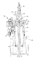
図4、図5、及び、図6は、大型2ストローククロスヘッドエンジンのための全体的に1で示されるシリンダライナーを示し、この場合、シリンダライナーにはシリンダカバー22が取り付けられ、また、シリンダカバー22には排気弁4が取り付けられる。エンジンサイズに応じて、シリンダライナー1は、一般に250mm〜1100mmの範囲のシリンダ内径と1000mm〜4500mmの範囲の対応する典型的な長さとを伴って異なるサイズで製造されてもよい。シリンダライナー1は、通常、鋳鉄で製造される。大型2ストローククロスヘッドエンジンは、燃焼室25内の圧力に耐える必要がある要素、例えばシリンダライナー1、ピストン10、及び、シリンダカバー22などに作用する重い荷重を伴う1:16〜1:20などの非常に高い有効圧縮比へ向けて開発される。
4, 5 and 6 show a cylinder liner, generally designated 1 for a large two-stroke crosshead engine, where a
図4には、シリンダライナー1がシリンダフレーム23内に装着されて示され、この場合、シリンダライナー1の上端にはシリンダカバー22がこれらの間に気密性の界面を伴って配置される。シリンダカバー22上に環状リテーナ30が嵌合され、この場合、シリンダカバー22の外側に突出するリム31が環状リテーナ30とシリンダライナー1の上端との間でクランプされる。
4 shows the
シリンダライナー1の軸方向範囲の中央付近におけるシリンダライナー1の厚さの急な移行部は、シリンダライナー1がシリンダフレーム23上に載置できるようにする肩部としての機能を果たす。環状リテーナ30は、シリンダカバースタッド24によって環状リテーナ30の上面に印加される大きな力によってシリンダカバー22に対して押圧され、また、シリンダカバー22は、環状リテーナ30によってシリンダライナー1に印加される大きな力によって押圧される。
The sharp transition of the thickness of the
燃料弁27がシリンダカバー22に取り付けられ、この場合、燃料弁27の前端のノズルが燃焼室25内へ突出する。
The
排気弁装置は排気弁4を備え、この排気弁4は、その弁棒と、弁座51に載置して示される弁体とを有する。
The exhaust valve device includes an
排気弁装置は、排気ベンド50を含むハウジング28を備える。排気ベンド50は、その一端が弁座51を備える排気弁の底側に対して開口し、その他端が排気弁ハウジング28の側面に対して開口する。弁ハウジング28の側面における排気ベンド50の開口は、排ガスリザーバ3に通じる排気ダクトに接続する。
The exhaust valve device includes a
排気弁ハウジングには、排気弁スピンドルを案内する孔が設けられる。液圧排気弁アクチュエータ52が排気弁ハウジング28の上側に取り付けられ、この液圧排気弁アクチュエータ52は、排気弁を開くために排気弁スピンドルの自由端に作用する。また、排気弁アクチュエータ52は、排気弁をその閉位置へ戻るように付勢するための空気圧スプリング53も含む。
The exhaust valve housing is provided with a hole for guiding the exhaust valve spindle. A hydraulic
排気弁ハウジング28には外側に突出する排気弁ハウジングフランジ29が設けられ、この排気弁ハウジングフランジ29には複数の貫通延在孔が設けられ、これらの孔を通じて排気弁スタッド32が突出する。排気弁スタッド32はシリンダカバー22の上端に固定される。ナット33が排気弁スタッド32の上端と係合し、このナット33は、排気弁ハウジング28をシリンダカバー22に対してボルト留めするために排気弁ハウジングフランジ29に作用する。
The
排気弁ハウジングフランジ29は、排気ベンド50の側面開口よりも下側に配置される。排気弁ハウジング28は、弁座51を形成するリング形状部材によって支持され、このリング形状部材は、排気弁を支持するためのシリンダカバー22の内側に突出する張出部42(図8)によって支持される。
The exhaust
排気弁ハウジングフランジ29は、弁ハウジング28の側面にある排気ベンド50の開口よりも下側に配置される。従来技術の排気弁では、排気弁スタッドのナットが、排気弁ハウジングの上端の表面、すなわち、排気ベンド50の側面開口よりも上側の表面と係合した。これらの従来技術の排気弁は、排気ベンドが排気スタッドのための経路内にあり、それにより、一般に4本の比較的大きな排気スタッドだけが配置されるという不都合を有する。排気スタッドのナット33が係合する表面を排気ベンド50の側面開口よりも下側に配置することにより、排気スタッドの長さをかなり減らすことができるとともに、多数の更に小さいスタッドを使用でき、それにより、想定し得るコスト低減が可能となる。また、これは、様々な弁の最適な位置決めも可能にする。
The exhaust
配管54は、液体冷却剤、例えば水を、シリンダライナー1の上部の冷却装置へ、例えば一実施形態ではシリンダカバー22と環状リテーナ30との間に配置される周方向冷却凹部39へ供給して除去する役目を果たす。
The
図7〜図13を参照して、シリンダ22及び環状リテーナ30について更に詳しく説明する。シリンダカバー22は、図8では燃料弁27が取り付けられた状態で示され、また、図9では燃料弁27が取り付けられない状態で示される。
The
シリンダカバー22は、上側47及び下側48を伴う環状本体を有する。下側48には、シリンダライナー1の上側環状面と係合するための下側環状接触面44が設けられる。上側47には、一実施形態では、排気弁スタッド32が固定される複数のネジ孔41が設けられる環状面45が形成され得る。環状本体は、燃焼室25の上部を形成するために下側48に対して開口する中空部49を画定する下部36を有する。シリンダカバー22の環状本体は、中空部49に対して開口するとともにシリンダカバー22の上側47に対して開口する中心通路38を画定する上部35を有し、それにより、通路38は、排気弁4が開放するときに排ガスが中空部49から排気ベンド50へと流れることができるようにする。一実施形態では、下部36が上部35に直接に接続され、或いは、図示のように、好ましくはテーパ状の移行部55が設けられる。
The
環状本体には、シリンダカバー22の下側48に、一体の径方向外側に突出するフランジ31が設けられる。径方向外側に突出するフランジ31は、環状リテーナ30を支持するための上方に向けられる接触面43を有する。径方向外側に突出するフランジ31は、好ましくは下側環状接触面44と同一平面内にある下方に向けられる表面を有する。
The annular main body is provided with a
中心通路38には、内側に向けられる環状張出部上に、排気弁の下方に面する環状接触面を支持するための上方に面する支持面42が設けられる。
The
一実施形態において、シリンダカバー22の環状本体は、材料の一体品によって形成される。すなわち、シリンダカバー22の本体は、1つの一体要素として形成される。
In one embodiment, the annular body of the
環状本体の構成は、それが略均一に配分される壁厚を有するようになっている。図示の実施形態では、環状部材のための略一定の壁厚を維持するために、下部36と上部35との間の移行部がテーパ部分55の形態を成す。しかしながら、下部36と上部35との間の移行部をテーパ状にする必要はなく、移行部を例えば直角移行部にすることができる。
The configuration of the annular body is such that it has a wall thickness that is distributed substantially uniformly. In the illustrated embodiment, the transition between the
環状本体には突出部56が設けられ、この突出部56は、燃料弁27を受ける孔34のためにこの場所に設けられる。図示の実施形態では、シリンダごとに3つの燃料弁があるが、エンジン形態に応じて、及び、エンジンを作動させるようになっている燃料の数に応じて、シリンダごとに2〜6個の燃料弁が存在し得る。
The annular body is provided with a
環状リテーナ30はシリンダカバー22とは別個の要素であり、また、環状リテーナ30は、環状リテーナ30の底面の径方向内側部分が径方向外側に突出するフランジ31の上方に向けられる接触面43と係合する状態で下部36の周囲に嵌合するように寸法付けられて形成される。
The
環状リテーナ30には、シリンダカバー22の下部36の外径に等しい又はこの外径よりも僅かに大きい直径を有する中心開口が設けられる。外側に突出するフランジ31の(外)径は、環状リテーナ30の中心開口の直径よりも大きい。
The
しかしながら、外側に突出するフランジ31の(外)径は環状リテーナ30の外径よりも小さく、それにより、シリンダカバースタッド24は、外側に突出するフランジ31を通過できるが、依然として環状リテーナ30における貫通延在孔46内に受けられる。貫通延在孔46は、シリンダカバースタッド24が径方向外側に突出するフランジ31の周囲に近接して配置されるように設けられる。
However, the (outer) diameter of the outwardly projecting
上部35の外径は、下部36の外径に等しく又はこの外径よりも小さく、それにより、環状リテーナ30をシリンダカバー22の本体上にわたって且つ外側に突出するフランジ31の上方に向けられる接触面43上に配置することができる。したがって、シリンダカバー22の最大外径は、径方向外側に突出するフランジ31によって形成される。また、この構造は、環状リテーナ30をシリンダカバー22から離れるように単に持ち上げるだけで環状リテーナ30を除去できるようにし、それにより、メンテナンスを容易にする。
The outer diameter of the
一実施形態では、環状冷却凹部39が下部36に形成されて環状リテーナ30により閉鎖される。環状冷却凹部は、周方向に略均一な冷却分布をもたらす。環状リテーナ30には、環状凹部39をシールする態様でシリンダカバー22の下部36を取り囲む強力な背面を形成するために直立リム40が設けられる。環状冷却凹部39と径方向外側に突出するフランジ31との間の丸みを帯びた移行部がこの移行部における張力を低減する。
In one embodiment, an
環状冷却凹部39は、シリンダカバー22の中間部分にある複数の略径方向に向けられる冷却チャネル37に接続し、また、冷却チャネル37は、排気弁を冷却するために排気弁の冷却チャネルに接続する。
The
シリンダカバー22の本体は、一実施形態では、鋳鉄又は鋳鋼から形成される。シリンダカバー22の本体は、他の実施形態では、高強度耐熱鋼、例えば鍛鋼から形成される。
In one embodiment, the body of the
一実施形態において、環状リテーナ30は、環状リテーナ30を鋳造によって製造できるようにする例えば鋳鉄又は低合金鋼などの比較的安価な材料から形成される。
In one embodiment, the
本明細書中の様々な実施形態と関連して本発明を説明してきた。しかしながら、特許請求の範囲に記載される発明を実施する際に、図面、開示内容、及び、添付の特許請求の範囲の検討により、開示された実施形態に対する他の変形を当業者が理解してもたらすことができる。特許請求の範囲において、用語「備える」は、他の要素又はステップを排除せず、また、不定冠詞「1つの(a)」又は「1つの(an)」は複数を排除しない。特定の手段が互いに異なる従属請求項に挙げられているという単なる事実は、これらの手段の組み合わせを有利に使用できないことを示唆しない。特許請求の範囲において使用される参照符号は、範囲を限定するように解釈されないものとする。 The invention has been described in connection with various embodiments herein. However, in carrying out the invention described in the claims, those skilled in the art will appreciate other variations to the disclosed embodiments upon review of the drawings, the disclosure, and the appended claims. Can bring. In the claims, the term “comprising” does not exclude other elements or steps, and the indefinite article “a” or “an” does not exclude a plurality. The mere fact that certain measures are recited in mutually different dependent claims does not indicate that a combination of these measured cannot be used to advantage. Any reference signs used in the claims shall not be construed as limiting the scope.
Claims (14)
− 上側(47)及び下側(48)を伴う環状本体を備え、
− 前記環状本体は、燃焼室(25)の上部を形成するために前記下側(48)に対して開口する中空部(49)を画定する下部(36)を有し、
− 前記環状本体は、排気弁(4)を収容するように形成された中心通路(38)を画定する上部(35)を有し、前記中心通路(38)は、前記中空部(49)に対して開口するとともに前記上側(47)に対して開口し、
− 前記環状本体は、前記下側(48)に、一体の径方向外側に突出するフランジ(31)を備え、
− 前記径方向外側に突出するフランジ(31)は、環状リテーナ(30)を支持するための上方に向けられる接触面(43)を有する、
シリンダカバー(22)。 A cylinder cover (22) for a compression ignition internal combustion engine with a large two-stroke turbocharger, the cylinder cover comprising:
-Comprising an annular body with an upper side (47) and a lower side (48);
The annular body has a lower part (36) defining a hollow part (49) opening to the lower side (48) to form an upper part of a combustion chamber (25);
The annular body has an upper portion (35) defining a central passage (38) formed to receive an exhaust valve (4) , the central passage (38) being in the hollow portion (49); And open to the upper side (47),
The annular body comprises a flange (31) projecting radially outward on the lower side (48);
The radially outwardly projecting flange (31) has an upwardly facing contact surface (43) for supporting the annular retainer (30);
Cylinder cover (22).
シリンダライナー(1)上のシリンダカバー(22)であって、前記シリンダライナー(1)がシリンダフレーム(23)によって支持される、シリンダカバー(22)と、
前記シリンダカバー(22)と係合する環状リテーナ(30)と、
前記シリンダカバー(22)を前記シリンダライナー(1)に対してクランプするために前記環状リテーナ(30)を前記シリンダフレーム(23)に接続する複数のシリンダカバースタッド(24)と、
を備え、
前記シリンダカバー(22)は、
上側(47)及び下側(48)を伴う環状本体を備え、
前記環状本体は、燃焼室(25)の上部を形成するために前記下側(48)に対して開口する中空部(49)を画定する下部(36)を有し、
前記環状本体は、排気弁(4)を収容するように形成された中心通路(38)を画定する上部(35)を有し、前記中心通路(38)は、前記中空部(49)に対して開口するとともに前記上側(47)に対して開口し、
前記環状本体は、前記下側(48)に、一体の径方向外側に突出するフランジ(31)を備え、
前記径方向外側に突出するフランジ(31)は、環状リテーナ(30)を支持するための上方に向けられる接触面(43)を有するエンジン。 A compression ignition internal combustion engine with a large two-stroke turbocharger having a crosshead, the engine comprising:
A cylinder cover (22) on the cylinder liner (1), wherein the cylinder liner (1) is supported by a cylinder frame (23);
An annular retainer (30) engaged with the cylinder cover (22);
A plurality of cylinder cover studs (24) connecting the annular retainer (30) to the cylinder frame (23) to clamp the cylinder cover (22) against the cylinder liner (1);
Equipped with a,
The cylinder cover (22)
Comprising an annular body with an upper side (47) and a lower side (48);
The annular body has a lower portion (36) defining a hollow portion (49) that opens to the lower side (48) to form an upper portion of a combustion chamber (25);
The annular body has an upper portion (35) defining a central passage (38) configured to receive an exhaust valve (4), the central passage (38) being in relation to the hollow portion (49). And open to the upper side (47),
The annular body is provided with a flange (31) protruding outward in an integral radial direction on the lower side (48),
Engine the radial flange projecting outwardly (31), that having a contact surface (43) directed upwardly for supporting the annular retainer (30).
Applications Claiming Priority (2)
| Application Number | Priority Date | Filing Date | Title |
|---|---|---|---|
| DKPA201670153A DK179175B1 (en) | 2016-03-16 | 2016-03-16 | A cylinder cover for a large two-stroke turbocharged compression-ignited internal combustion engine |
| DKPA201670153 | 2016-03-16 |
Publications (2)
| Publication Number | Publication Date |
|---|---|
| JP2017166478A JP2017166478A (en) | 2017-09-21 |
| JP6298552B2 true JP6298552B2 (en) | 2018-03-20 |
Family
ID=59905539
Family Applications (1)
| Application Number | Title | Priority Date | Filing Date |
|---|---|---|---|
| JP2017026153A Active JP6298552B2 (en) | 2016-03-16 | 2017-02-15 | Cylinder cover for a compression ignition internal combustion engine with a large two-stroke turbocharger |
Country Status (4)
| Country | Link |
|---|---|
| JP (1) | JP6298552B2 (en) |
| KR (2) | KR101813947B1 (en) |
| CN (1) | CN107201964B (en) |
| DK (1) | DK179175B1 (en) |
Cited By (1)
| Publication number | Priority date | Publication date | Assignee | Title |
|---|---|---|---|---|
| US12043585B1 (en) | 2019-07-29 | 2024-07-23 | Flashset, Llc | Rapid-setting cellular backfill with calcium sulfoaluminate cement and other powder-sized filler materials |
Families Citing this family (1)
| Publication number | Priority date | Publication date | Assignee | Title |
|---|---|---|---|---|
| JP7403321B2 (en) * | 2020-01-10 | 2023-12-22 | 株式会社ジャパンエンジンコーポレーション | frame |
Family Cites Families (18)
| Publication number | Priority date | Publication date | Assignee | Title |
|---|---|---|---|---|
| JPS4616185Y1 (en) * | 1967-06-22 | 1971-06-05 | ||
| JPS6038994U (en) * | 1983-08-26 | 1985-03-18 | トヨタ自動車株式会社 | Cylinder head cover |
| JPS57180133U (en) * | 1981-05-13 | 1982-11-15 | ||
| JPS5985471A (en) * | 1982-11-09 | 1984-05-17 | Mitsubishi Heavy Ind Ltd | Combustion equipment for diesel engine |
| US4825817A (en) * | 1987-09-08 | 1989-05-02 | Romanowski Jack R | Replaceable combustion chamber for two-cycle engines |
| DK277690D0 (en) | 1990-11-22 | 1990-11-22 | Man B & W Diesel Gmbh | CYLINDER LINING FOR A WATER-COOLED COMBUSTION ENGINE |
| JPH056751U (en) * | 1991-07-08 | 1993-01-29 | 日本電気株式会社 | Coaxial connector |
| JP3337307B2 (en) * | 1994-02-21 | 2002-10-21 | 三菱重工業株式会社 | Water injection diesel engine |
| JP2001323852A (en) * | 2000-05-12 | 2001-11-22 | Toyota Motor Corp | Intake and exhaust manifold |
| DK177917B1 (en) * | 2001-05-23 | 2015-01-05 | Man Diesel & Turbo Deutschland | Cylinder in a two-stroke long-rinsed cross-head motor and method for reducing NOx formation |
| EP1329628B1 (en) * | 2002-01-16 | 2007-06-13 | Wärtsilä Schweiz AG | Cylinder head for a piston combustion engine with a cooling conduit system |
| KR100601062B1 (en) * | 2002-05-21 | 2006-07-19 | 맨 비 앤드 더블유 디젤 에이/에스 | Support plate for cylinder liner of large two stroke internal combustion engine |
| DE10332226B4 (en) * | 2003-07-16 | 2006-03-30 | Man B & W Diesel A/S | Two-stroke diesel engine |
| JP2005299563A (en) * | 2004-04-14 | 2005-10-27 | Toyota Motor Corp | Fixed structure |
| DE102010011070B4 (en) * | 2010-03-11 | 2012-04-05 | Man Diesel & Turbo, Filial Af Man Diesel & Turbo Se, Tyskland | valve assembly |
| JP5909043B2 (en) * | 2011-01-31 | 2016-04-26 | 三菱重工業株式会社 | Internal combustion engine cooling structure |
| AT513053B1 (en) * | 2012-06-26 | 2014-03-15 | Avl List Gmbh | Internal combustion engine, in particular large diesel engine |
| JP2015132191A (en) * | 2014-01-10 | 2015-07-23 | 三菱重工業株式会社 | Engine cylinder cooling device, cylinder cooling method, method of modifying cylinder cooling device, and engine and ship each equipped with cylinder cooling device |
-
2016
- 2016-03-16 DK DKPA201670153A patent/DK179175B1/en active
-
2017
- 2017-02-15 JP JP2017026153A patent/JP6298552B2/en active Active
- 2017-03-14 KR KR1020170031593A patent/KR101813947B1/en active Active
- 2017-03-16 CN CN201710157177.6A patent/CN107201964B/en active Active
- 2017-09-07 KR KR1020170114342A patent/KR101889709B1/en active Active
Cited By (1)
| Publication number | Priority date | Publication date | Assignee | Title |
|---|---|---|---|---|
| US12043585B1 (en) | 2019-07-29 | 2024-07-23 | Flashset, Llc | Rapid-setting cellular backfill with calcium sulfoaluminate cement and other powder-sized filler materials |
Also Published As
| Publication number | Publication date |
|---|---|
| DK179175B1 (en) | 2018-01-08 |
| JP2017166478A (en) | 2017-09-21 |
| KR20170107911A (en) | 2017-09-26 |
| DK201670153A1 (en) | 2017-10-02 |
| CN107201964B (en) | 2020-02-04 |
| CN107201964A (en) | 2017-09-26 |
| KR101813947B1 (en) | 2018-01-02 |
| KR20170107940A (en) | 2017-09-26 |
| KR101889709B1 (en) | 2018-08-20 |
Similar Documents
| Publication | Publication Date | Title |
|---|---|---|
| KR102181690B1 (en) | A large two-stroke uniflow scavenged gaseous fueled engine | |
| CN101970812B (en) | Large two-stroke diesel engine with electronically controlled exhaust valve actuation system | |
| JP6298552B2 (en) | Cylinder cover for a compression ignition internal combustion engine with a large two-stroke turbocharger | |
| KR102110588B1 (en) | A cylinder liner for a two-stroke crosshead engine | |
| JP6493987B2 (en) | Cylinder, liner and crosshead type 2-stroke internal combustion engine | |
| JP6530042B2 (en) | Fuel valve nozzle for injecting fuel into a cylinder of a large turbocharged two-stroke compression ignition internal combustion engine and engine therefor | |
| EP3336342B1 (en) | Nozzle for fuel valve for injecting fuel into the cylinders of a large turbocharged two-stroke compression-ignited internal combustion engine | |
| DK182243B1 (en) | System comprising a large turbocharged two-strok uniflow crosshead internal combustion engine and a hydraulic preloaded tie rod assembly | |
| CN111742132B (en) | Scavenging rectification structure of marine diesel engine | |
| CN101495718B (en) | Large two-stroke diesel engine with outwardly moving exhaust valves | |
| KR101860474B1 (en) | A cylinder liner for a two-stroke crosshead engine | |
| JP6209241B2 (en) | Large turbocharged self-igniting two-cycle internal combustion engine and seal ring therefor |
Legal Events
| Date | Code | Title | Description |
|---|---|---|---|
| A521 | Request for written amendment filed |
Free format text: JAPANESE INTERMEDIATE CODE: A523 Effective date: 20170906 |
|
| A131 | Notification of reasons for refusal |
Free format text: JAPANESE INTERMEDIATE CODE: A131 Effective date: 20171212 |
|
| A521 | Request for written amendment filed |
Free format text: JAPANESE INTERMEDIATE CODE: A523 Effective date: 20171222 |
|
| TRDD | Decision of grant or rejection written | ||
| A01 | Written decision to grant a patent or to grant a registration (utility model) |
Free format text: JAPANESE INTERMEDIATE CODE: A01 Effective date: 20180206 |
|
| A61 | First payment of annual fees (during grant procedure) |
Free format text: JAPANESE INTERMEDIATE CODE: A61 Effective date: 20180223 |
|
| R150 | Certificate of patent or registration of utility model |
Ref document number: 6298552 Country of ref document: JP Free format text: JAPANESE INTERMEDIATE CODE: R150 |
|
| S533 | Written request for registration of change of name |
Free format text: JAPANESE INTERMEDIATE CODE: R313533 |
|
| R350 | Written notification of registration of transfer |
Free format text: JAPANESE INTERMEDIATE CODE: R350 |
|
| R250 | Receipt of annual fees |
Free format text: JAPANESE INTERMEDIATE CODE: R250 |
|
| R250 | Receipt of annual fees |
Free format text: JAPANESE INTERMEDIATE CODE: R250 |
|
| R250 | Receipt of annual fees |
Free format text: JAPANESE INTERMEDIATE CODE: R250 |
|
| R250 | Receipt of annual fees |
Free format text: JAPANESE INTERMEDIATE CODE: R250 |
|
| R250 | Receipt of annual fees |
Free format text: JAPANESE INTERMEDIATE CODE: R250 |
|
| R250 | Receipt of annual fees |
Free format text: JAPANESE INTERMEDIATE CODE: R250 |