JP2005299563A - Fixed structure - Google Patents
Fixed structure Download PDFInfo
- Publication number
- JP2005299563A JP2005299563A JP2004119138A JP2004119138A JP2005299563A JP 2005299563 A JP2005299563 A JP 2005299563A JP 2004119138 A JP2004119138 A JP 2004119138A JP 2004119138 A JP2004119138 A JP 2004119138A JP 2005299563 A JP2005299563 A JP 2005299563A
- Authority
- JP
- Japan
- Prior art keywords
- hole
- fixing member
- fixing
- bolt fastening
- outer peripheral
- Prior art date
- Legal status (The legal status is an assumption and is not a legal conclusion. Google has not performed a legal analysis and makes no representation as to the accuracy of the status listed.)
- Pending
Links
Images


Landscapes
- Cylinder Crankcases Of Internal Combustion Engines (AREA)
Abstract
【課題】組み立て作業性を効率的に向上させることのできる固定構造を提供する。
【解決手段】内周ブロック30と外周ブロック40とに分割形成されたシリンダブロック14を有する内燃機関10にあって、シリンダヘッド12と内周ブロック30と外周ブロック40とを一体に固定する。シリンダヘッド12には第2貫通孔26が、内周ブロック30には第1貫通孔38が、外周ブロック40にはボルト締結穴46がそれぞれ同軸上を有して形成される。固定部材50が第1貫通孔38を通してボルト締結穴46に挿入固定される。これにより、固定部材50の凸部54と外周ブロック40の当接面42aとの間にアッパデッキ部22が狭持・係止される。ヘッドボルト28が第2貫通孔26から固定部材50の内部を通してボルト締結穴46に螺着される。これにより、シリンダヘッド12と外周ブロック40とが締め付け固定される。
【選択図】 図7A fixing structure capable of efficiently improving assembly workability is provided.
In an internal combustion engine 10 having a cylinder block 14 divided into an inner peripheral block 30 and an outer peripheral block 40, a cylinder head 12, an inner peripheral block 30 and an outer peripheral block 40 are fixed integrally. A second through hole 26 is formed in the cylinder head 12, a first through hole 38 is formed in the inner peripheral block 30, and a bolt fastening hole 46 is formed in the outer peripheral block 40 so as to be coaxial. The fixing member 50 is inserted and fixed to the bolt fastening hole 46 through the first through hole 38. Thereby, the upper deck part 22 is pinched and latched between the convex part 54 of the fixing member 50 and the contact surface 42 a of the outer peripheral block 40. The head bolt 28 is screwed into the bolt fastening hole 46 from the second through hole 26 through the inside of the fixing member 50. Thereby, the cylinder head 12 and the outer peripheral block 40 are fastened and fixed.
[Selection] Figure 7
Description
本発明は、例えば内燃機関のシリンダブロックとシリンダヘッドとの締結固定等における3つの構造体の一体固定を行う固定構造に関する。 The present invention relates to a fixing structure that integrally fixes three structures in, for example, fastening and fixing a cylinder block and a cylinder head of an internal combustion engine.
往復運動式の内燃機関は、一般に、シリンダボアが形成されたシリンダブロックとシリンダヘッドとを備えている。近年、例えば特許文献1に見られるように、シリンダブロックを、シリンダヘッドが載置されるアッパデッキ部及びシリンダブロック内壁が一体形成された内周ブロックとシリンダブロック外壁により形成される外周ブロックとに分割形成するようにした内燃機関が提案されている。こうした内燃機関では、ヘッドボルトによる締結固定によって、シリンダヘッド、内周ブロック、及び外周ブロックが一体に形成される。
ところで、こうした内燃機関では、シリンダヘッド、内周ブロック、及び外周ブロックを位置決めしつつ一体に締結固定する必要があることから、その位置決め作業が極めて困難なものになるなど、その組み立てにかかる作業の煩雑化は避けられない。 By the way, in such an internal combustion engine, it is necessary to fasten and fix the cylinder head, the inner peripheral block, and the outer peripheral block integrally, so that the positioning work becomes extremely difficult. Complexity is inevitable.
しかも、上記内燃機関は前記ヘッドボルトを外した場合にシリンダヘッドとシリンダブロックとが分離されることに加えて、そのシリンダブロックが内周ブロックと外周ブロックとに分離される構成であるために、同内燃機関のメンテナンスに際してシリンダヘッドを取り外す度に、そうした組み立てにかかる困難な作業を行わなければならない。 Moreover, the internal combustion engine has a configuration in which when the head bolt is removed, the cylinder head and the cylinder block are separated, and the cylinder block is separated into an inner peripheral block and an outer peripheral block. Each time the cylinder head is removed for maintenance of the internal combustion engine, such a difficult work for assembly must be performed.
なお、上述したシリンダヘッド、内周ブロック及び外周ブロックを一体に固定する固定構造に限らず、3つの構造体をボルト締結によって一体に固定する固定構造にあっては、そうした実情は概ね共通したものとなっている。 In addition to the above-described fixing structure for fixing the cylinder head, the inner peripheral block and the outer peripheral block integrally, such a situation is generally common in a fixing structure in which three structures are fixed integrally by bolt fastening. It has become.
本発明は、上記実情に鑑みてなされたものであり、その目的は、組み立て作業性を効率的に向上させることのできる固定構造を提供することにある。 This invention is made | formed in view of the said situation, The objective is to provide the fixing structure which can improve assembly workability | operativity efficiently.
以下、上記目的を達成するための手段及びその作用効果について説明する。
先ず、請求項1に記載の発明は、第1構造体と第2構造体との間に第3構造体を挟み込んだ状態で、これら3つの構造体を一体に固定する固定構造であって、前記第2構造体に形成されて、その前記第3構造体との当接面に開口するボルト締結穴と、前記ボルト締結穴と同軸を有して前記第3構造体に形成され、その内部を貫通して該第3構造体の前記第2構造体との当接面及び前記第1構造体との当接面にそれぞれ開口する第1貫通孔と、同じく前記ボルト締結穴と同軸を有して前記第1構造体に形成され、その内部を貫通して前記第3構造体との当接面に開口する第2貫通孔と、一端が前記ボルト締結穴に挿入固定される管状の固定部材であって、前記第1貫通孔を介して該固定部材の前記一端を前記ボルト締結穴に挿入固定した状態で前記第2構造体との間に前記第3構造体を狭持して同第3構造体を係止する凸部がその外周面に形成された固定部材と、前記第2貫通孔から前記固定部材の内部を通して前記ボルト締結穴に螺着されて、前記第1構造体と前記第2構造体とを締め付け固定するボルトと、を備えることをその要旨とする。
Hereinafter, means for achieving the above-described object and its operation and effects will be described.
First, the invention according to
上記構成では、第3構造体に形成された第1貫通孔を通して固定部材をボルト締結穴に挿入固定すると、固定部材の凸部と第2構造体との間に第3構造体が狭持されて係止されるようになる。そして管状に形成された固定部材の内部を通して第1構造体の第2貫通孔から第2構造体のボルト締結穴にボルトを螺着し、第1構造体と第2構造体とを締め付け固定することで、3つの構造体が一体に固定される。 In the above configuration, when the fixing member is inserted and fixed into the bolt fastening hole through the first through hole formed in the third structure, the third structure is sandwiched between the convex portion of the fixing member and the second structure. And become locked. Then, a bolt is screwed into the bolt fastening hole of the second structure from the second through hole of the first structure through the inside of the fixing member formed in a tubular shape, and the first structure and the second structure are fastened and fixed. Thus, the three structures are fixed together.
こうした固定構造では、第2構造体と第3構造体との位置合わせ、それら第2及び第3構造体と第1構造体との位置合わせを個別に行うことができる。そのため、ボルトのみで3者を同時固定する場合のように固定時に3つの構造体の位置合わせを同時に行う必要が無くなり、一体固定に際しての構造体同士の位置合わせ作業を容易とすることができる。 In such a fixed structure, the second structure and the third structure can be aligned, and the second and third structures and the first structure can be aligned individually. Therefore, it is not necessary to simultaneously align the three structures at the time of fixing, as in the case where the three members are fixed simultaneously with only the bolts, and the alignment work between the structures at the time of integral fixing can be facilitated.
しかも、こうした固定構造では、固定部材及びボルトは、各々の締結に必要な貫通孔及びボルト締結穴を共用している。そのため、ボルトのみを用いて固定を行う場合に比して、固定構造の配設スペースの増大は最小限に留まることになる。 Moreover, in such a fixing structure, the fixing member and the bolt share the through hole and the bolt fastening hole necessary for each fastening. Therefore, as compared with the case where the fixing is performed using only the bolt, the increase in the space for disposing the fixing structure is minimized.
またこうした固定構造では、ボルトが取り外されると、第2構造体及び第3構造体から第1構造体は分離されるものの、第2構造体と第3構造体とは固定部材により固定されたままとなる。そのため、第1構造体の分離時に不必要に第2構造体と第3構造体とが分離されないようにすることができる。 In such a fixing structure, when the bolt is removed, the first structure is separated from the second structure and the third structure, but the second structure and the third structure remain fixed by the fixing member. It becomes. Therefore, it is possible to prevent the second structure and the third structure from being unnecessarily separated at the time of separation of the first structure.
したがって上記構成によれば、第1〜第3構造体の組み立ての作業性を効率的に向上させることができる。
また、請求項2に記載の発明は、シリンダヘッドが載置されるアッパデッキ部及びシリンダブロック内壁が一体形成された内周ブロックとシリンダブロック外壁を構成する外周ブロックとに分割形成されたシリンダブロックを有する内燃機関にあって、前記シリンダヘッドと前記内周ブロックと前記外周ブロックとを一体に固定する固定構造であって、前記外周ブロックに形成され、その前記アッパデッキ部との当接面に開口するボルト締結穴と、前記ボルト締結穴と同軸を有して前記アッパデッキ部に形成され、その内部を貫通して該アッパデッキ部の前記外周ブロックとの当接面及び前記シリンダヘッドとの当接面にそれぞれ開口する第1貫通孔と、同じく前記ボルト締結穴と同軸を有して前記シリンダヘッドに形成され、その内部を貫通して前記アッパデッキ部との当接面に開口する第2貫通孔と、一端が前記ボルト締結穴に挿入固定される管状の固定部材であって、前記第1貫通孔を介して該固定部材の前記一端を前記ボルト締結穴に挿入固定した状態で前記外周ブロックの頂面との間に前記アッパデッキ部を狭持して同アッパデッキ部を係止する凸部がその外周面に形成された固定部材と、前記第2貫通孔から前記固定部材の内部を通して前記ボルト締結穴に螺着されて、前記シリンダヘッドと前記外周ブロックとを締め付け固定するヘッドボルトと、を備えることをその要旨とする。
Therefore, according to the said structure, the workability | operativity of the assembly of the 1st-3rd structure can be improved efficiently.
According to a second aspect of the present invention, there is provided a cylinder block formed by dividing an upper deck portion on which the cylinder head is placed and an inner peripheral block integrally formed with an inner wall of the cylinder block and an outer peripheral block constituting the outer wall of the cylinder block. An internal combustion engine having a fixing structure that integrally fixes the cylinder head, the inner peripheral block, and the outer peripheral block, and is formed in the outer peripheral block, and is open to a contact surface with the upper deck portion. A bolt fastening hole, which is coaxially formed with the bolt fastening hole, is formed in the upper deck portion, penetrates through the inside thereof, and comes into contact with the outer peripheral block of the upper deck portion and the contact surface with the cylinder head. Each of the first through holes that are open and the same as the bolt fastening holes are coaxially formed in the cylinder head and penetrate the inside thereof. A second through hole that opens to a contact surface with the upper deck portion, and a tubular fixing member having one end inserted and fixed in the bolt fastening hole, and the fixing member is connected to the fixing member via the first through hole. A fixing member in which a convex portion is formed on the outer peripheral surface of the upper deck portion so that the upper deck portion is sandwiched between the top surface of the outer peripheral block with the one end inserted and fixed in the bolt fastening hole. And a head bolt that is screwed into the bolt fastening hole through the inside of the fixing member from the second through hole to fasten and fix the cylinder head and the outer peripheral block.
上記構成では、内周ブロックのアッパデッキ部に形成された第1貫通孔を通して固定部材をボルト締結穴に挿入固定すると、固定部材の凸部と外周ブロックとの間にアッパデッキ部が狭持され、それによりシリンダブロックを構成する内周ブロックと外周ブロックとが固定される。そして管状に形成された固定部材の内部を通してシリンダヘッドの第2貫通孔から外周ブロックのボルト締結穴にボルトを螺着し、シリンダヘッドと外周ブロックとを締め付け固定することで、同シリンダヘッドとシリンダブロックの内・外周ブロックが一体に固定される。 In the above configuration, when the fixing member is inserted and fixed into the bolt fastening hole through the first through hole formed in the upper deck portion of the inner peripheral block, the upper deck portion is sandwiched between the convex portion of the fixing member and the outer peripheral block. As a result, the inner peripheral block and the outer peripheral block constituting the cylinder block are fixed. Then, a bolt is screwed into the bolt fastening hole of the outer peripheral block from the second through hole of the cylinder head through the inside of the fixing member formed in a tubular shape, and the cylinder head and the outer peripheral block are fastened and fixed. The inner and outer peripheral blocks of the block are fixed together.
こうした固定構造では、その配設スペースが殆ど増大されていないにも拘わらず、シリンダブロックを構成する両ブロックの固定と、そうしたシリンダブロックに対するシリンダヘッドの固定とを各々個別に行えるようにすることができる。しかも、シリンダブロックからシリンダヘッドを分離した際に、両ブロックが不必要に分離されてしまわないようにすることができる。したがって上記固定構造の採用により、固定構造の配設スペースの増大を抑えつつ、上記の如く分割形成されたシリンダブロックを備える内燃機関でのシリンダヘッド、シリンダブロックの組み立て作業性を効率的に向上することができる。 In such a fixing structure, it is possible to fix both the blocks constituting the cylinder block and the cylinder head to the cylinder block individually, although the arrangement space is hardly increased. it can. In addition, when the cylinder head is separated from the cylinder block, both blocks can be prevented from being unnecessarily separated. Therefore, by adopting the above-described fixing structure, the assembling workability of the cylinder head and the cylinder block in the internal combustion engine having the cylinder block divided and formed as described above is efficiently improved while suppressing an increase in the arrangement space of the fixing structure. be able to.
また、請求項3に記載の発明は、請求項1又は2に記載の固定構造において、前記固定部材の前記ボルト締結穴に挿入固定される一端とは反対側の端部は、前記第2貫通孔に嵌入されることをその要旨とする。 According to a third aspect of the present invention, in the fixing structure according to the first or second aspect, an end of the fixing member opposite to one end inserted and fixed in the bolt fastening hole is the second penetration. The gist is to be inserted into the hole.
上記構成では、固定部材の一端はボルト締結穴に挿入固定され、その反対側の端部は第2貫通孔に嵌入されるため、固定部材を介してボルト締結穴と第2貫通孔との位置合わせがなされるようになる。すなわち、固定部材による固定により、ボルト締結穴の形成された第2構造体/外周ブロックと第2貫通孔の形成された第1構造体/シリンダヘッドとが自ずと位置合わせされるようになる。そのため、固定に際しての位置合わせ作業を更に容易とすることができる。 In the above configuration, one end of the fixing member is inserted and fixed into the bolt fastening hole, and the opposite end is inserted into the second through hole, so that the positions of the bolt fastening hole and the second through hole are interposed via the fixing member. Matching will be done. That is, the second structure / outer peripheral block in which the bolt fastening hole is formed and the first structure / cylinder head in which the second through hole is formed are naturally aligned by the fixing by the fixing member. Therefore, it is possible to further facilitate the alignment work at the time of fixing.
また、請求項4に記載の発明は、請求項1〜3のいずれか一項に記載の固定構造において、前記第1貫通孔の内周面には、前記固定部材の外周面と嵌合される嵌合部が形成されてなることをその要旨とする。 According to a fourth aspect of the present invention, in the fixing structure according to any one of the first to third aspects, the inner peripheral surface of the first through hole is fitted to the outer peripheral surface of the fixing member. The gist is that a fitting portion is formed.
上記構成では、固定部材の一端がボルト締結穴に挿入固定され、第1貫通孔内周面の嵌合部にその外周面が嵌合されることから、固定部材を介してボルト締結穴と第1貫通孔との位置合わせがなされるようになる。すなわち、固定部材による固定を通じて、ボルト締結穴の形成された第2構造体/内周ブロック(アッパデッキ部)と第1貫通孔の形成された第3構造体/外周ブロックとが自ずと位置合わせされるようになる。そのため、固定に際しての位置合わせ作業を更に容易とすることができる。 In the above configuration, one end of the fixing member is inserted and fixed in the bolt fastening hole, and the outer peripheral surface thereof is fitted to the fitting portion of the inner peripheral surface of the first through hole. Position alignment with 1 through-hole comes to be made. That is, the second structure / inner peripheral block (upper deck portion) in which the bolt fastening holes are formed and the third structure / outer peripheral block in which the first through holes are formed are naturally aligned through fixing by the fixing member. It becomes like this. Therefore, it is possible to further facilitate the alignment work at the time of fixing.
また、請求項5に記載の発明は、請求項1〜4のいずれか一項に記載の固定構造において、前記固定部材の一端は、前記ボルト締結穴に対してねじ止め固定されてなることをその要旨とする。
The invention according to claim 5 is the fixing structure according to any one of
上記構成によれば、ボルト締結穴に対する固定部材の挿入固定及びその離脱を容易且つ確実に行うことができるようになる。
また、請求項6に記載の発明は、請求項5に記載の固定構造において、前記固定部材には、その延伸方向に直交する内周面の断面形状が非円形状とされた部分が形成されてなることをその要旨とする。
According to the above configuration, the fixing member can be inserted and fixed to and from the bolt fastening hole and removed easily and reliably.
According to a sixth aspect of the present invention, in the fixing structure according to the fifth aspect, the fixing member is formed with a portion in which a cross-sectional shape of the inner peripheral surface perpendicular to the extending direction is noncircular. The gist of this is
上記構成によれば、非円形状とされた内周面に噛合する工具を利用することで、固定部材を回転させ、ボルト締結穴へのねじ止め及びその取り外しを容易に行うことができる。
また、請求項7に記載の発明は、請求項1〜6のいずれか一項に記載の固定構造において、前記固定部材は、焼結材にて形成されてなることをその要旨とする。
According to the said structure, a fixing member can be rotated by utilizing the tool meshed with the inner peripheral surface made into the non-circular shape, and the screwing to a bolt fastening hole and its removal can be performed easily.
The gist of the invention according to claim 7 is that the fixing member is formed of a sintered material in the fixing structure according to any one of
上記構成では、固定部材を比較的容易に高寸法精度で形成することができる。
また、請求項8に記載の発明は、第1構造体と第2構造体との間に第3構造体を挟み込んだ状態で一体に固定する固定構造であって、前記第2構造体と前記第3構造体とを、軸心部に貫通孔の形成された第1ボルトで締結するとともに、前記第1構造体と前記第2構造体とを、前記第1ボルトの前記貫通孔を通して挿入される第2ボルトで締結することをその要旨とする。
In the above configuration, the fixing member can be formed relatively easily with high dimensional accuracy.
The invention according to claim 8 is a fixing structure in which the third structure is fixed integrally with the third structure sandwiched between the first structure and the second structure, and the second structure and the second structure The third structure is fastened with a first bolt having a through hole formed in the axial center portion, and the first structure and the second structure are inserted through the through hole of the first bolt. The gist is to fasten with the second bolt.
上記構成によれば、第2構造体に対する第3構造体の着脱、及びそれら第2構造体及び第3構造体に対する第1構造体の着脱を個別に行うことができるようになる。しかも、第1ボルトが第2ボルトの軸心部に形成された貫通孔を挿通して締結されるため、単一のボルトのみで3者を同時固定する場合に比して、固定構造の配設スペースの増大は最小限に留められる。 According to the above configuration, the third structure can be attached to and detached from the second structure, and the first structure can be attached to and detached from the second structure and the third structure individually. In addition, since the first bolt is inserted and fastened through the through-hole formed in the shaft center portion of the second bolt, the arrangement of the fixing structure is larger than the case where the three members are fixed simultaneously with only a single bolt. The increase in installation space is kept to a minimum.
以下、本発明を内燃機関に適用した一実施の形態について説明する。
図1に、本実施の形態が適用される内燃機関の斜視構造を示す。
内燃機関10は、シリンダヘッド12及びシリンダブロック14を備えている。そして、シリンダヘッド12とシリンダブロック14とは、ガスケット16を介してボルト締結にて固定されている。なお、シリンダヘッド12の上方にはヘッドカバーが、シリンダブロック14の下方にはオイルパン(共に図示略)がそれぞれ取付けられる。
Hereinafter, an embodiment in which the present invention is applied to an internal combustion engine will be described.
FIG. 1 shows a perspective structure of an internal combustion engine to which the present embodiment is applied.
The
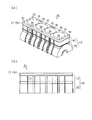
図2(a)にシリンダブロック14の斜視構造を、図2(b)にその側面構造をそれぞれ示す。
シリンダブロック14には、その上部に4つのシリンダボア18が形成され、その下部にはクランクケース部20が設けられている。そして、シリンダブロック14の頂部には、シリンダヘッド12が載置される平板状のアッパデッキ部22が設けられている。
FIG. 2A shows a perspective structure of the
The
このシリンダブロック14は、シリンダ周囲に形成されるウォータジャケットとなる部位を境に分割形成されている。具体的には、上記アッパデッキ部22とウォータジャケットのシリンダ側の周壁とが一体に形成された内周ブロック30と、ウォータジャケットを囲むシリンダブロック外壁と上記クランクケース部20とが一体に形成された外周ブロック40とに分割形成されている。
The
以下、それら内周ブロック30及び外周ブロック40について具体的に説明する。
ここでは先ず、内周ブロック30について説明する。
図3(a)に内周ブロック30の斜視構造を、図3(b)にその側面構造をそれぞれ示す。内周ブロック30は4つの円管体を連続して繋げた形状のシリンダ部32を備えている。それら各円管体の内周面34が上記シリンダボア18の周壁面を構成し、各円管体の外周面36がウォータジャケットのシリンダ側の壁面を構成する。上記アッパデッキ部22は、上記シリンダ部32の上端に一体形成されている。
Hereinafter, the inner
First, the inner
FIG. 3A shows a perspective structure of the inner
次に、外周ブロック40について説明する。
図4(a)に外周ブロック40の斜視構造を、図4(b)にその側面構造をそれぞれ示す。外周ブロック40はクランクケース部20とその上部に形成されるシリンダ外壁部42とを備えている。シリンダ外壁部42はその内周面44が上記内周ブロック30(図3参照)のシリンダ部32の外周面36と対向するように略環状に成形されており、この内周面44がウォータジャケットの外壁を構成する。
Next, the outer
FIG. 4A shows a perspective structure of the outer
以下、シリンダヘッド12、内周ブロック30、及び外周ブロック40を一体に固定する固定構造について説明する。
図5に示されるように、本実施の形態では先ず、内周ブロック30と外周ブロック40とが固定部材50によって一体に固定されてシリンダブロック14が一体形成される。
Hereinafter, a fixing structure that integrally fixes the
As shown in FIG. 5, in this embodiment, first, the inner
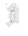
上記内周ブロック30のアッパデッキ部22にはそれぞれ固定部材50が挿通される複数(本実施の形態では10個、図3参照)の第1貫通孔38が形成されている。第1貫通孔38にはその内周面上端が段状に拡径された形状の嵌合部38aが形成されている。また、外周ブロック40のシリンダ外壁部42には、上記第1貫通孔38と同軸を有するとともにアッパデッキ部22との当接面42aに開口する複数(本実施の形態では10個、図4参照)のボルト締結穴46が形成されている。各ボルト締結穴46の内周面上部には雌ねじ47が、また内周面下部には雌ねじ48がそれぞれ形成されている。
A plurality of first through holes 38 (10 in the present embodiment, see FIG. 3) through which the fixing
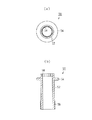
図6(a)に固定部材50の平面構造を、図6(b)にその側面構造をそれぞれ示す。
固定部材50は、軸心部に貫通孔の形成された円管形状の本体52と、同本体52の外周面がその全周にわたって円環形状に突出形成された凸部54とを備えている。この凸部54は本体52の軸方向における中間位置に形成され、上記第1貫通孔38(図5)の嵌合部38aに対応する形状に形成されている。また、本体52の外周面にあってその外周ブロック40(図5)側の端部には雄ねじ56が形成されている。更に、本体52の上記アッパデッキ部22(図5)側の端部58の内周面は、同本体52の延伸方向に直交する方向における断面形状が多角形状に形成されている。この多角形状としては、正六角形或いは複数の正六角形を組み合わせた形状を採用することが望ましい。なお、固定部材50は焼結材により形成される。
FIG. 6A shows a planar structure of the fixing
The fixing
図5に示すように、内周ブロック30と外周ブロック40との固定に際しては、アッパデッキ部22の当接面22aとシリンダ外壁部42の頂面(当接面42a)とが当接するように、内周ブロック30のシリンダ部32が外周ブロック40のシリンダ外壁部42内に挿入される。そして、固定部材50が内周ブロック30の第1貫通孔38に挿通され、同固定部材50の雄ねじ56と上記ボルト締結穴46の雌ねじ47とが螺合される。また、このとき固定部材50の凸部54が第1貫通孔38の嵌合部38aに嵌入される。なお、上記螺合は、上記端部58の内周面に噛合する工具を利用して固定部材50を回転させることにより行われる。
As shown in FIG. 5, when the inner
このように固定することにより、固定部材50の凸部54と外周ブロック40との間にアッパデッキ部22が挟持され、内周ブロック30と外周ブロック40とが一体に固定される。また、シリンダ部32の外周面36、シリンダ外壁部42の内周面44、及び上記アッパデッキ部22の当接面22aによってシリンダ周囲にウォータジャケット24が区画形成される。なお、内周ブロック30と外周ブロック40との接合面には、ウォータジャケット24からの冷却水の漏れをシールするために、シール材を介設したりシール剤を塗布したりする等といったシール処理が施される。
By fixing in this way, the
また、この固定に際して嵌合部38aの内周面に凸部54の外周面が嵌合されることから、固定部材50を介して第1貫通孔38とボルト締結穴46との位置合わせがなされるようになる。すなわち、固定部材50による固定を通じて、内周ブロック30と外周ブロック40とが自ずと位置合わせされるようになる。
Further, since the outer peripheral surface of the
なお、上述のように固定部材50の本体52の軸方向における中間位置に凸部54が形成されているために、同固定部材50は、その本体52の端部58がアッパデッキ部22の上面から突出するように外周ブロック40に固定される。
In addition, since the
次に、図7に示されるように、一体に形成されたシリンダブロック14にシリンダヘッド12が固定される。
上記シリンダヘッド12には、上記ボルト締結穴46と同軸を有するとともに内部を貫通してアッパデッキ部22との当接面12aに開口する複数(本実施の形態では10個)の第2貫通孔26が形成されている。それら第2貫通孔26はその上記シリンダブロック14側の端部の内径が段状に拡径された形状に形成されている。
Next, as shown in FIG. 7, the
The
そして、シリンダヘッド12をシリンダブロック14に載置する際には、各第2貫通孔26の拡径された部分に、上述した態様でアッパデッキ部22の上面から突出している各固定部材50の本体52が嵌入される。これにより、ボルト締結穴46と第2貫通孔26との位置合わせ、すなわちシリンダヘッド12と外周ブロック40との位置合わせがなされるようになる。なお、詳しくは、シリンダヘッド12はガスケット16を間に挟んだ状態でシリンダブロック14に載置される。
When the
更に、このように載置された状態で、ヘッドボルト28がシリンダヘッド12の第2貫通孔26及び固定部材50の本体52に挿通されて上記ボルト締結穴46の雌ねじ48に螺着される。これにより、シリンダヘッド12とシリンダブロック14とが一体に固定される。
Further, the
このように本実施の形態では、シリンダブロック14を構成する内周ブロック30と外周ブロック40とが固定部材50によって固定される。更には、固定部材50の内部及び第2貫通孔26を通してボルト締結穴46にヘッドボルト28を螺着し、シリンダブロック14と外周ブロック40とを締め付け固定することにより、シリンダヘッド12とシリンダブロック14とが一体に固定される。
Thus, in the present embodiment, the inner
これにより、配設スペースが殆ど増大されていないにも拘わらず、シリンダブロック14を構成する内周ブロック30及び外周ブロック40の固定と、そうしたシリンダブロック14に対するシリンダヘッド12の固定とを各々個別に行えるようにすることができる。しかも、シリンダブロック14からシリンダヘッド12を分離した際に、内周ブロック30と外周ブロック40とが不必要に分離されてしまわないようにすることができる。
Thereby, although the arrangement space is hardly increased, the inner
したがって、固定構造の配設スペースの増大を抑えつつ、上記の如く分割形成されたシリンダブロック14を備える内燃機関10の組み立ての作業性を効率的に向上させることができるようになる。
Therefore, it is possible to efficiently improve the workability of assembling the
以上説明したように、本実施の形態によれば、以下に記載する効果が得られるようになる。
(1)内燃機関10の組み立ての作業性を効率的に向上させることができる。
As described above, according to the present embodiment, the effects described below can be obtained.
(1) The workability of assembling the
(2)固定部材50の本体52の端部58をシリンダヘッド12の第2貫通孔26に嵌入するようにしたために、固定部材50による固定により、内周ブロック30と外周ブロック40とが自ずと位置合わせされるようになる。そのため、固定に際しての位置合わせ作業を更に容易とすることができる。
(2) Since the
(3)第1貫通孔38の内周面に固定部材50の凸部54の外周面と嵌合する嵌合部38aを形成するようにした。そのため、固定部材50による固定を通じて、内周ブロック30と外周ブロック40とが自ずと位置合わせされるようになり、上記位置合わせ作業を更に容易とすることができる。
(3) The
(4)固定部材50を外周ブロック40のボルト締結穴46に対してねじ止め固定するようにした。このため、ボルト締結穴46に対する固定部材50の挿入固定及びその離脱を容易且つ確実に行うことができるようになる。
(4) The fixing
(5)固定部材50の端部58に、その延設方向に直交する方向における断面形状が多角形状とされた部分を形成するようにした。このため、多角形状に形成された内周面に噛合する工具を利用することで、固定部材50を回転させ、同固定部材50のボルト締結穴46へのねじ止め及びその取り外しを容易に行うことができる。
(5) The
(6)固定部材50を焼結材にて形成するようにしたために、同固定部材50を比較的容易に高寸法精度で形成することができる。
なお、上記実施の形態は、以下のように変更して実施してもよい。
(6) Since the fixing
The embodiment described above may be modified as follows.
・上記実施の形態において、固定部材50の本体52の内周面にあってその断面形状が多角形状になるように形成する部分を、シリンダヘッド12側の端部58以外の部分に変更してもよい。また、多角形状に限らず、例えば楕円形状となるように形成すること等も可能である。要は、本体52の内周面の断面形状の少なくとも一部を非円形状に形成することにより、同内周面に噛合する工具を用いて固定部材を回転させることができる。
In the above embodiment, the portion formed on the inner peripheral surface of the
・また、そうした非円形状に形成される部分を省略することも可能である。この場合、例えば本体52の外周面の一部を非円形状に形成する等といった構成により、固定部材を回転させることが可能になる。
-It is also possible to omit such a non-circular portion. In this case, for example, the fixing member can be rotated by a configuration in which a part of the outer peripheral surface of the
・固定部材50の凸部54の形状及び嵌合部38aの形状は、嵌合部に対して凸部が嵌合可能な形状であれば、それぞれ任意に変更可能である。
・前記凸部54に代えて、固定部材50の端部58に凸部を形成するようにしてもよい。こうした構成にあっても、固定部材をその凸部の一部がアッパデッキ部22から突出する形状に形成し、同凸部をシリンダヘッド12の第2貫通孔26に嵌入することにより、外周ブロック40に対するシリンダヘッド12の位置合わせを行うことができる。
-The shape of the
In place of the
・シリンダヘッド12と外周ブロック40との位置合わせが適正になされるのであれば、必ずしも固定部材50の一部を第2貫通孔26に嵌入する必要はない。
・固定部材50を焼結材以外の材料を用いて形成するようにしてもよい。具体的には、例えば鍛造によって成形した素材に機械加工を加えて形成することなどが可能である。
If the
-You may make it form the fixing
・固定部材50の雄ねじ56や外周ブロック40の雌ねじ47としては、固定部材50の軸方向やボルト締結穴46の延設方向に対して、歯先を繋ぐ線が平行に延びるねじを形成することの他、歯先を繋ぐ線がテーパ状に延びる、いわゆるテーパねじを形成することなども可能である。
As the
・内周ブロック30と外周ブロック40との当接面における十分な面圧を確保可能であれば、固定部材50の雄ねじ56及び外周ブロック40の雌ねじ47を共に省略するとともに、固定部材を外周ブロックのボルト締結穴46に圧入固定するようにしてもよい。
If the sufficient contact pressure on the contact surface between the inner
・また、ヘッドボルト28が配設される部分の全て(本実施の形態では10箇所)に固定部材を設ける必要はなく、そのうちの幾つかに固定部材を配設するようにしてもよい。
・本発明は、上述した構成以外の内燃機関にも適用することができる。要は、シリンダヘッドが載置されるアッパデッキ部及びシリンダブロック内壁が一体形成された内周ブロックとシリンダブロック外壁を構成する外周ブロックとに分割形成されたシリンダブロックを有する内燃機関であれば、本発明は上記各実施の形態と同様、或いはそれに準じた態様で適用することが可能である。
In addition, it is not necessary to provide fixing members at all of the portions where the
The present invention can be applied to an internal combustion engine other than the configuration described above. In short, if the engine is an internal combustion engine having a cylinder block that is divided into an upper peripheral part on which the cylinder head is placed and an inner peripheral block integrally formed with an inner wall of the cylinder block and an outer peripheral block constituting the outer wall of the cylinder block, The invention can be applied in a manner similar to or equivalent to the above-described embodiments.
・また、内燃機関にも限らず、第1構造体と第2構造体との間に第3構造体を挟み込んだ状態で、これら3つの構造体を一体に固定するものであれば、本発明にかかる固定構造は適宜適用可能である。 In addition, the present invention is not limited to an internal combustion engine, and the present invention can be used as long as these three structures are integrally fixed with the third structure sandwiched between the first structure and the second structure. The fixing structure according to can be applied as appropriate.
10…内燃機関、12…シリンダヘッド、12a,22a,42a…当接面、14…シリンダブロック、16…ガスケット、18…シリンダボア、20…クランクケース部、22…アッパデッキ部、24…ウォータジャケット、26…第2貫通孔、28…ヘッドボルト、30…内周ブロック、32…シリンダ部、34,44…内周面、36…外周面、38…第1貫通孔、38a…嵌合部、40…外周ブロック、42…シリンダ外壁部、46…ボルト締結穴、47,48,56…雌ねじ、50…固定部材、52…本体、54…凸部、58…端部。
DESCRIPTION OF
Claims (8)
前記第2構造体に形成されて、その前記第3構造体との当接面に開口するボルト締結穴と、
前記ボルト締結穴と同軸を有して前記第3構造体に形成され、その内部を貫通して該第3構造体の前記第2構造体との当接面及び前記第1構造体との当接面にそれぞれ開口する第1貫通孔と、
同じく前記ボルト締結穴と同軸を有して前記第1構造体に形成され、その内部を貫通して前記第3構造体との当接面に開口する第2貫通孔と、
一端が前記ボルト締結穴に挿入固定される管状の固定部材であって、前記第1貫通孔を介して該固定部材の前記一端を前記ボルト締結穴に挿入固定した状態で前記第2構造体との間に前記第3構造体を狭持して同第3構造体を係止する凸部がその外周面に形成された固定部材と、
前記第2貫通孔から前記固定部材の内部を通して前記ボルト締結穴に螺着されて、前記第1構造体と前記第2構造体とを締め付け固定するボルトと、
を備えることを特徴とする固定構造。 A fixing structure that integrally fixes these three structures in a state where the third structure is sandwiched between the first structure and the second structure,
A bolt fastening hole formed in the second structure and opening in a contact surface with the third structure;
The third structure body is formed coaxially with the bolt fastening hole, penetrates the inside of the third structure body, and abuts the contact surface of the third structure body with the second structure body and the first structure body. First through-holes each opening on a contact surface;
Similarly, a second through hole that is coaxially formed with the bolt fastening hole and is formed in the first structure body and penetrates through the inside thereof and opens at a contact surface with the third structure body,
A tubular fixing member having one end inserted and fixed in the bolt fastening hole, and the second structure body in a state in which the one end of the fixing member is inserted and fixed into the bolt fastening hole via the first through-hole. A fixing member formed on its outer peripheral surface with a convex portion for holding the third structure and locking the third structure between
A bolt that is screwed into the bolt fastening hole through the inside of the fixing member from the second through hole, and fastens and fixes the first structure and the second structure;
A fixing structure characterized by comprising:
前記外周ブロックに形成され、その前記アッパデッキ部との当接面に開口するボルト締結穴と、
前記ボルト締結穴と同軸を有して前記アッパデッキ部に形成され、その内部を貫通して該アッパデッキ部の前記外周ブロックとの当接面及び前記シリンダヘッドとの当接面にそれぞれ開口する第1貫通孔と、
同じく前記ボルト締結穴と同軸を有して前記シリンダヘッドに形成され、その内部を貫通して前記アッパデッキ部との当接面に開口する第2貫通孔と、
一端が前記ボルト締結穴に挿入固定される管状の固定部材であって、前記第1貫通孔を介して該固定部材の前記一端を前記ボルト締結穴に挿入固定した状態で前記外周ブロックの頂面との間に前記アッパデッキ部を狭持して同アッパデッキ部を係止する凸部がその外周面に形成された固定部材と、
前記第2貫通孔から前記固定部材の内部を通して前記ボルト締結穴に螺着されて、前記シリンダヘッドと前記外周ブロックとを締め付け固定するヘッドボルトと、
を備えることを特徴とする固定構造。 An internal combustion engine having a cylinder block divided into an upper deck portion on which a cylinder head is placed and an inner peripheral block integrally formed with an inner wall of the cylinder block and an outer peripheral block constituting the outer wall of the cylinder block, and the cylinder head, A fixing structure for integrally fixing the inner peripheral block and the outer peripheral block;
A bolt fastening hole formed in the outer peripheral block and opened to a contact surface with the upper deck portion;
A first shaft that is coaxial with the bolt fastening hole and is formed in the upper deck portion, passes through the inside thereof, and opens to a contact surface of the upper deck portion with the outer peripheral block and a contact surface of the cylinder head. A through hole,
A second through hole that is also coaxial with the bolt fastening hole, is formed in the cylinder head, and penetrates the inside thereof to open to a contact surface with the upper deck portion;
A tubular fixing member having one end inserted into and fixed to the bolt fastening hole, and the top surface of the outer peripheral block in a state in which the one end of the fixing member is inserted and fixed to the bolt fastening hole through the first through hole A fixing member formed on its outer peripheral surface with a convex portion for holding the upper deck portion between and holding the upper deck portion between
A head bolt that is screwed into the bolt fastening hole through the inside of the fixing member from the second through hole, and fastens and fixes the cylinder head and the outer peripheral block;
A fixing structure characterized by comprising:
Priority Applications (1)
| Application Number | Priority Date | Filing Date | Title |
|---|---|---|---|
| JP2004119138A JP2005299563A (en) | 2004-04-14 | 2004-04-14 | Fixed structure |
Applications Claiming Priority (1)
| Application Number | Priority Date | Filing Date | Title |
|---|---|---|---|
| JP2004119138A JP2005299563A (en) | 2004-04-14 | 2004-04-14 | Fixed structure |
Publications (1)
| Publication Number | Publication Date |
|---|---|
| JP2005299563A true JP2005299563A (en) | 2005-10-27 |
Family
ID=35331407
Family Applications (1)
| Application Number | Title | Priority Date | Filing Date |
|---|---|---|---|
| JP2004119138A Pending JP2005299563A (en) | 2004-04-14 | 2004-04-14 | Fixed structure |
Country Status (1)
| Country | Link |
|---|---|
| JP (1) | JP2005299563A (en) |
Cited By (1)
| Publication number | Priority date | Publication date | Assignee | Title |
|---|---|---|---|---|
| JP2017166478A (en) * | 2016-03-16 | 2017-09-21 | マン ディーゼル アンド ターボ フィリアル ア マン ディーゼル アンド ターボ エスイー チュスクランMAN Diesel & Turbo,filial af MAN Diesel & Turbo SE,Tyskland | Cylinder cover for compression ignition internal combustion engine with large-sized two-stroke turbocharger |
-
2004
- 2004-04-14 JP JP2004119138A patent/JP2005299563A/en active Pending
Cited By (1)
| Publication number | Priority date | Publication date | Assignee | Title |
|---|---|---|---|---|
| JP2017166478A (en) * | 2016-03-16 | 2017-09-21 | マン ディーゼル アンド ターボ フィリアル ア マン ディーゼル アンド ターボ エスイー チュスクランMAN Diesel & Turbo,filial af MAN Diesel & Turbo SE,Tyskland | Cylinder cover for compression ignition internal combustion engine with large-sized two-stroke turbocharger |
Similar Documents
| Publication | Publication Date | Title |
|---|---|---|
| KR101452876B1 (en) | Connecting structure for pressure piping | |
| US6729291B1 (en) | Multipart cooled piston for an internal combustion engine | |
| KR101503961B1 (en) | Camshaft module | |
| GB2325035A (en) | Interference bolt connection creating plastic deformation within ajoining holes to secure strict axial alignment | |
| JP5021437B2 (en) | Steel pipe pile connection structure | |
| CN101253322A (en) | Two-piece piston for internal combustion engines | |
| KR20040020843A (en) | Common rail for diesel engines | |
| WO2019123991A1 (en) | Engine | |
| US6364565B1 (en) | Piston pin assembly | |
| JP2005201118A (en) | Cylinder block fastening structure | |
| JP2005299563A (en) | Fixed structure | |
| WO2010051843A1 (en) | Dismountable multi-piece crankshaft | |
| CN100582464C (en) | Multipart piston for an internal combustion engine | |
| JP4471933B2 (en) | Cylinder head structure of direct injection diesel engine | |
| JP2001059464A (en) | Common rail | |
| JP2011241700A (en) | Bearing structure of camshaft | |
| KR20130041907A (en) | Jacket for internal combustion engine | |
| US9745917B2 (en) | Multi-part crankcase and assembly method | |
| JP5447007B2 (en) | Masking jig | |
| US6178849B1 (en) | Connecting rod assembly for an internal combustion engine | |
| JP2001153109A (en) | Hydraulic cylinder | |
| JP2554841B2 (en) | Pneumatic core clamp shaft | |
| JP5028309B2 (en) | Positioning and fixing method, rotary compressor manufacturing method, bolt fastening device, and rotary compressor | |
| JP2006138226A (en) | Internal combustion engine | |
| JP2010156211A (en) | Camshaft device mounting structure |