JP6296551B2 - Hot water storage tank unit - Google Patents

Hot water storage tank unit Download PDF

Info

Publication number
JP6296551B2
JP6296551B2 JP2014170969A JP2014170969A JP6296551B2 JP 6296551 B2 JP6296551 B2 JP 6296551B2 JP 2014170969 A JP2014170969 A JP 2014170969A JP 2014170969 A JP2014170969 A JP 2014170969A JP 6296551 B2 JP6296551 B2 JP 6296551B2
Authority
JP
Japan
Prior art keywords
hot water
outer box
storage tank
pipe
water storage
Prior art date
Legal status (The legal status is an assumption and is not a legal conclusion. Google has not performed a legal analysis and makes no representation as to the accuracy of the status listed.)
Active
Application number
JP2014170969A
Other languages
Japanese (ja)
Other versions
JP2016044921A (en
JP2016044921A5 (en
Inventor
伏木 隆之
隆之 伏木
宏太朗 渡邊
宏太朗 渡邊
島崎 幸治
幸治 島崎
加藤 聡
聡 加藤
信 小曽戸
信 小曽戸
Current Assignee (The listed assignees may be inaccurate. Google has not performed a legal analysis and makes no representation or warranty as to the accuracy of the list.)
Hitachi Appliances Inc
Original Assignee
Hitachi Appliances Inc
Priority date (The priority date is an assumption and is not a legal conclusion. Google has not performed a legal analysis and makes no representation as to the accuracy of the date listed.)
Filing date
Publication date
Application filed by Hitachi Appliances Inc filed Critical Hitachi Appliances Inc
Priority to JP2014170969A priority Critical patent/JP6296551B2/en
Publication of JP2016044921A publication Critical patent/JP2016044921A/en
Publication of JP2016044921A5 publication Critical patent/JP2016044921A5/ja
Application granted granted Critical
Publication of JP6296551B2 publication Critical patent/JP6296551B2/en
Active legal-status Critical Current
Anticipated expiration legal-status Critical

Links

Images

Landscapes

  • Details Of Fluid Heaters (AREA)
  • Housings, Intake/Discharge, And Installation Of Fluid Heaters (AREA)

Description

本発明は、貯湯タンクユニットに関する。 The present invention also relates to a hot water storage Tankuyuni' door.

従来の貯湯タンクユニットとして、貯湯タンクの周囲を複数の成形断熱材(いわゆる、発泡スチロール)で覆い、成形断熱材の周囲を外装ケース(外箱)で覆うものが提案されている(特許文献1参照)。   A conventional hot water storage tank unit has been proposed in which a hot water storage tank is covered with a plurality of molded heat insulating materials (so-called foamed polystyrene) and a molded heat insulating material is covered with an outer case (outer box) (see Patent Document 1). ).

特開2011−106791号公報JP 2011-106791 A

しかしながら、特許文献1に記載の貯湯タンクユニットの断熱材として、外箱と貯湯タンクとの間に発泡液を注入して発泡させる発泡断熱材を用いた場合、発泡液が発泡する際の圧力によって貯湯タンクに接続された配管が位置ずれして、外箱の外部において既定の位置で接続される配管や弁などを接続することができなくなる問題があった。   However, as a heat insulating material for the hot water storage tank unit described in Patent Document 1, when a foamed heat insulating material is used that injects a foaming liquid between the outer box and the hot water storage tank and foams, the pressure when the foaming liquid is foamed The piping connected to the hot water storage tank is displaced, and there is a problem that it becomes impossible to connect piping or valves connected at a predetermined position outside the outer box.

そこで、配管を位置決めして固定する固定部材を外箱内に設けると、外箱内の構造が複雑になり、製造工程が煩雑になるとともに、発泡断熱材を隙間無く充填することが困難になる新たな問題が発生する。   Therefore, if a fixing member for positioning and fixing the piping is provided in the outer box, the structure in the outer box becomes complicated, the manufacturing process becomes complicated, and it becomes difficult to fill the foam heat insulating material without any gaps. New problems arise.

本発明は前記従来の問題を解決するものであり、簡単な構成で配管を位置決めすることが可能な貯湯タンクユニットを提供することを目的とする。 The present invention is the is intended to solve the conventional problems, and an object thereof is to provide a hot water storage Tankuyuni' bets capable of positioning the pipe with a simple structure.

本発明の貯湯タンクユニットは、貯湯タンクと、前記貯湯タンクを収容する外箱と、前記貯湯タンクと接続され、前記外箱の外部に引き出される配管と、前記外箱と前記貯湯タンクとの間に満たされている発泡断熱材と、を備え、前記外箱には、前記発泡断熱材を設ける際に前記発泡液が発泡する際の圧力によって当該外箱が変形するのを防止する発泡管理冶具が当該外箱のそれぞれの面に接する板材を備えて当該外箱の周囲全体を取り囲むように取り付けられ、前記発泡管理冶具には、回動しながら動作する前記板材に前記配管を位置決めする位置決め部材が設けられ、前記配管の先端部は、前記外箱に形成された貫通孔から突出し、前記配管の先端部の接続口には、当該接続口を閉塞する円錐部を有する栓体が取り付けられ、前記位置決め部材には、当該位置決め部材の回動方向に沿って形成され、かつ、前記円錐部を通過できない幅の長孔が形成され、前記長孔の長手方向の両端部および前記幅方向の両端部は、前記円錐部の斜面と平行な角度で形成され、前記位置決め部材は、前記発泡管理冶具の板材を回動させて前記外箱に取り付ける際の動作力を用いて、前記端部を前記円錐部の斜面に当接させて当該端部によって当該斜面が押圧されることで、前記配管の軸方向と前記貫通孔の軸方向とが一致するように前記配管を位置決めする部材であることを特徴とする。 The hot water storage tank unit of the present invention includes a hot water storage tank, an outer box that accommodates the hot water storage tank, a pipe connected to the hot water storage tank and drawn out of the outer box, and between the outer box and the hot water storage tank. And a foam control jig for preventing the outer box from being deformed by the pressure when the foaming liquid is foamed when the foam heat insulating material is provided in the outer box. Is provided with a plate material in contact with each surface of the outer box and is attached so as to surround the entire periphery of the outer box , and the foam management jig includes a positioning member that positions the pipe on the plate material that operates while rotating. A tip of the pipe protrudes from a through-hole formed in the outer box, and a plug having a conical portion that closes the connection port is attached to the connection port of the tip of the pipe, Said positioning The member is formed with a long hole formed in the rotation direction of the positioning member and having a width that cannot pass through the conical part, and both ends in the longitudinal direction of the long hole and both ends in the width direction are The positioning member is formed at an angle parallel to the inclined surface of the conical portion, and the positioning member rotates the plate material of the foam management jig and attaches the end portion to the outer box by using an operating force. It is a member that positions the pipe so that the axial direction of the pipe and the axial direction of the through hole coincide with each other by being brought into contact with the slope of the pipe and being pressed by the end portion. To do.

本発明によれば、簡単な構成で配管を位置決めすることが可能な貯湯タンクユニットを提供できる。 The present invention can provide a hot water storage Tankuyuni' bets capable of positioning the pipe with a simple structure.

第1実施形態に係る貯湯タンクユニットを備えた給湯機を示す全体構成図である。It is a whole lineblock diagram showing the water heater provided with the hot water storage tank unit concerning a 1st embodiment. 第1実施形態に係る貯湯タンクユニット内部を上方からみたときの断面図である。It is sectional drawing when the hot water storage tank unit inside which concerns on 1st Embodiment is seen from upper direction. (a)は発泡液注入時の発泡断熱材の流れを示す模式図、(b)は発泡断熱材の発泡途中の状態を示す模式図である。(A) is a schematic diagram which shows the flow of the foam heat insulating material at the time of foaming liquid injection | pouring, (b) is a schematic diagram which shows the state in the middle of foaming of a foam heat insulating material. (a)は貯湯タンクから外箱の外部に引き出される配管を示す斜視図、(b)は配管に栓体とシール材を取り付けた状態を示す斜視図、(c)はさらに抜け止め冶具を取り付けた状態を示す斜視図である。(A) is a perspective view showing piping pulled out from the hot water storage tank to the outside of the outer box, (b) is a perspective view showing a state where a stopper and a sealing material are attached to the piping, and (c) is further attached with a retaining jig. FIG. 位置決め部材を示し、(a)は平面図、(b)は(a)のA−A断面図、(c)は(a)のB−B断面図である。The positioning member is shown, (a) is a plan view, (b) is an AA sectional view of (a), and (c) is a BB sectional view of (a). 横向きに位置ずれした配管を位置決めする場合の動作説明図であり、(a)は位置決め前、(b)は位置決め途中、(c)は位置決め完了時である。It is operation | movement explanatory drawing in the case of positioning the pipe displaced in the horizontal direction, (a) is before positioning, (b) is in the middle of positioning, (c) is the time of completion of positioning. 上下向きに位置ずれした配管を位置決めする場合の動作説明図であり、(a)は位置決め前、(b)は位置決め途中、(c)は位置決め完了時である。It is operation | movement explanatory drawing in the case of positioning the pipe displaced in the up-down direction, (a) is before positioning, (b) is in the middle of positioning, (c) is the time of positioning completion. 前後方向に位置ずれした配管を位置決めする場合の動作説明図であり、(a)は位置決め前、(b)は位置決め途中、(c)は位置決め完了時である。It is operation | movement explanatory drawing when positioning the pipe | tube shifted in the front-back direction, (a) is before positioning, (b) is in the middle of positioning, (c) is the time of positioning completion. 第2実施形態に係る貯湯タンクユニットにおける配管の位置決め方法を説明する動作説明図であり、(a)は位置決め前、(b)は位置決め完了時である。It is operation | movement explanatory drawing explaining the positioning method of piping in the hot water storage tank unit which concerns on 2nd Embodiment, (a) is before positioning and (b) is the time of completion of positioning.

以下、本発明の実施形態に係る貯湯タンクユニット1について図1ないし図9を参照して説明する。   Hereinafter, a hot water storage tank unit 1 according to an embodiment of the present invention will be described with reference to FIGS. 1 to 9.

(第1実施形態)
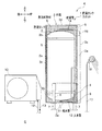
まず、本実施形態に係る貯湯タンクユニット1を備えた給湯機Kについて図1を参照して説明する。図1は、第1実施形態に係る貯湯タンクユニットを備えた給湯機を示す全体構成図である。なお、以下では、図1に示す上下方向および前後方向、図2に示す前後左右方向を基準にして説明する。
図1に示すように、給湯機(給湯ユニット)Kは、貯湯タンクユニット1、ヒートポンプユニット10を含んで構成されている。
(First embodiment)
First, the hot water heater K provided with the hot water storage tank unit 1 according to the present embodiment will be described with reference to FIG. FIG. 1 is an overall configuration diagram showing a water heater provided with a hot water storage tank unit according to the first embodiment. In the following, description will be made with reference to the vertical direction and the front-rear direction shown in FIG. 1 and the front-rear and left-right directions shown in FIG.
As shown in FIG. 1, the water heater (hot water supply unit) K includes a hot water storage tank unit 1 and a heat pump unit 10.

貯湯タンクユニット1は、貯湯タンク2、外箱3、内脚4、真空断熱材5、発泡断熱材6を含んで構成されている。   The hot water storage tank unit 1 includes a hot water storage tank 2, an outer box 3, an inner leg 4, a vacuum heat insulating material 5, and a foam heat insulating material 6.

貯湯タンク2は、例えば、ステンレス鋼などの材料によって形成され、円筒形状の胴板2a、胴板2aの上部開口を覆う略お椀状の上部鏡板2b、胴板2aの下部開口を覆う略お椀状の下部鏡板2c、の3部材を溶接することで構成されている。また、貯湯タンク2の外面(前面)には、上下方向に間隔を置いて複数の温度センサ(サーミスタ、不図示)が設けられている。   The hot water storage tank 2 is formed of a material such as stainless steel, for example, and has a cylindrical body plate 2a, a substantially bowl-shaped upper end plate 2b that covers the upper opening of the body plate 2a, and a substantially bowl-like shape that covers the lower opening of the body plate 2a. It is comprised by welding three members of the lower end plate 2c. A plurality of temperature sensors (thermistors, not shown) are provided on the outer surface (front surface) of the hot water storage tank 2 at intervals in the vertical direction.

外箱3は、貯湯タンク2を収容する鋼板製のものであり、貯湯タンク2の、前方に位置する前板3a、側方に位置する側板3b,3b(図2参照)、後方に位置する後板(背板)3c、上方に位置する上板(天板)3dおよび下方(底側)に位置する底板3eによって縦長の箱状に構成されている。   The outer box 3 is made of a steel plate that accommodates the hot water storage tank 2, and the front plate 3 a located on the front side, the side plates 3 b and 3 b located on the side (see FIG. 2), and the rear side of the hot water storage tank 2. The rear plate (back plate) 3c, the upper plate (top plate) 3d located above, and the bottom plate 3e located below (bottom side) constitute a vertically long box shape.

内脚4は、外箱3内において貯湯タンク2を支持するものであり、貯湯タンク2の周囲に120度間隔で配置されている。また、一の内脚4は、貯湯タンク2の前端部(最も前方に位置する部分)に配置され、他の内脚4は、貯湯タンク2の左右斜め後部に配置されている。なお、内脚4の本数は、3本に限定されるものではなく、4本以上であってもよい。   The inner legs 4 support the hot water storage tank 2 in the outer box 3 and are arranged around the hot water storage tank 2 at intervals of 120 degrees. Further, one inner leg 4 is disposed at the front end portion (the frontmost portion) of the hot water storage tank 2, and the other inner leg 4 is disposed at the diagonally rear left and right portions of the hot water storage tank 2. The number of inner legs 4 is not limited to three, and may be four or more.

底板3eの下面には、各内脚4に対応する位置に外脚(製品脚)7が固定されている。この外脚7は、アンカーボルト(不図示)などを介して設置箇所Gに固定されている。   Outer legs (product legs) 7 are fixed to the bottom surface of the bottom plate 3 e at positions corresponding to the inner legs 4. The outer leg 7 is fixed to the installation location G via an anchor bolt (not shown).

真空断熱材5は、シート状のものであり、貯湯タンク2の胴板2aの周囲に巻かれている。また、真空断熱材5は、グラスウールなどのガラス繊維からなるコア材を外包材などで被覆して、外包材の内部が真空引きされることで構成されている。外包材は、ガスバリア性を有するアルミニウム製のラミネートフィルムなどで構成されている。なお、図1では、真空断熱材5を貯湯タンク2の外壁面に接するように配置した場合を例に挙げて説明したが、これに限定されるものではなく、外箱3の内壁面に接するように配置する構成であってもよい。また、真空断熱材5を、貯湯タンク2の外壁面と外箱3の内壁面の双方に設ける構成であってもよく、真空断熱材5を設けないで構成してもよい。   The vacuum heat insulating material 5 is in the form of a sheet and is wound around the body plate 2 a of the hot water storage tank 2. Moreover, the vacuum heat insulating material 5 is comprised by coat | covering the core material which consists of glass fibers, such as glass wool, with an outer packaging material etc., and the inside of an outer packaging material is evacuated. The outer packaging material is made of an aluminum laminate film having gas barrier properties. In addition, in FIG. 1, although the case where the vacuum heat insulating material 5 was arrange | positioned so that it might contact | connect the outer wall surface of the hot water storage tank 2 was mentioned as an example, it is not limited to this, It contacts the inner wall surface of the outer box 3 The arrangement may be as follows. Moreover, the structure which provides the vacuum heat insulating material 5 in both the outer wall surface of the hot water storage tank 2 and the inner wall surface of the outer box 3 may be sufficient, and you may comprise without providing the vacuum heat insulating material 5. FIG.

発泡断熱材6は、発泡スチロールのような予め成形された断熱材(成形断熱材)ではなく、貯湯タンク2と外箱3との間の隙間(空間)に発泡液(原液)を注入し、注入後に発泡させることで構成されるものである。この発泡断熱材6としては、例えば、硬質ポリウレタンフォームが用いられる。この硬質ポリウレタンフォームは、ポリオール成分とイソシアネート成分の2つのウレタン原液を、発泡剤、触媒、整泡剤の存在下で反応させることにより得られるものである。発泡剤としては、シクロペンタン、水、炭酸ガスなどである。なお、発泡断熱材6は、硬質ポリウレタンフォームに限定されるものではない。   The foam heat insulating material 6 is not a pre-formed heat insulating material (molded heat insulating material) such as foamed polystyrene, but a foaming liquid (raw solution) is injected into the gap (space) between the hot water storage tank 2 and the outer box 3 and injected. It is comprised by making it foam later. As the foam heat insulating material 6, for example, a rigid polyurethane foam is used. This rigid polyurethane foam is obtained by reacting two urethane stock solutions of a polyol component and an isocyanate component in the presence of a foaming agent, a catalyst, and a foam stabilizer. Examples of the foaming agent include cyclopentane, water, and carbon dioxide gas. The foam heat insulating material 6 is not limited to the rigid polyurethane foam.

貯湯タンク2の下部には、水道水が導入される給水管11(配管)が接続されている。貯湯タンク2の下部の水は、ポンプ(不図示)によって入水管(ヒートポンプ往き管)12(配管)を介してヒートポンプユニット10に導入される。ヒートポンプユニット10で加熱された温水は、出湯管(ヒートポンプ戻り管)13(配管)を介して貯湯タンク2の上部に導入される。   A water supply pipe 11 (pipe) into which tap water is introduced is connected to the lower part of the hot water storage tank 2. The water in the lower part of the hot water storage tank 2 is introduced into the heat pump unit 10 by a pump (not shown) through a water inlet pipe (heat pump forward pipe) 12 (pipe). Hot water heated by the heat pump unit 10 is introduced into the upper part of the hot water storage tank 2 via a hot water discharge pipe (heat pump return pipe) 13 (pipe).

このような貯湯タンク2内の温水の温度は、例えば、鉛直方向下方から上方にいくにしたがって高くなる。すなわち、貯湯タンク2内の下部から上部にかけて、相対的に低温、中温、高温の温度分布となっている。例えば、貯湯タンク2内の上部で約90℃、中間部で約50℃となっている。   The temperature of the hot water in such a hot water storage tank 2 increases, for example, as it goes upward from the lower side in the vertical direction. That is, the temperature distribution is relatively low, medium and high from the lower part to the upper part in the hot water storage tank 2. For example, the temperature is about 90 ° C. at the upper part of the hot water storage tank 2 and about 50 ° C. at the intermediate part.

ヒートポンプユニット10は、貯湯タンク2から取り出した水を加熱するものであり、例えば、冷媒(例えば、二酸化炭素)を圧縮して高温・高圧にする圧縮機と、圧縮機から吐出された冷媒と貯湯タンク2からの水とを熱交換することによって貯湯タンク2からの水を加熱する凝縮器と、凝縮器から流出する冷媒を減圧する減圧弁と、大気中の熱を吸熱して減圧した冷媒を蒸発させる蒸発器と、を備えて構成されている。なお、本実施形態では、加熱手段として、ヒートポンプユニット10を例に挙げて説明したが、加熱手段として、電気ヒータやガスで加熱するものであってもよい。   The heat pump unit 10 heats the water taken out from the hot water storage tank 2. For example, the heat pump unit 10 compresses a refrigerant (for example, carbon dioxide) to a high temperature and high pressure, and the refrigerant discharged from the compressor and the hot water storage. A condenser that heats the water from the hot water storage tank 2 by exchanging heat with the water from the tank 2, a pressure reducing valve that depressurizes the refrigerant flowing out of the condenser, and a refrigerant that absorbs heat in the atmosphere and depressurizes the refrigerant. And an evaporator for evaporating. In the present embodiment, the heat pump unit 10 is described as an example of the heating unit. However, the heating unit may be heated by an electric heater or gas.

貯湯タンク2の上部から取り出された湯は、給湯管14(配管)を通り、給水管11に分岐して接続された分岐給水管(不図示)からの水と、混合弁16を介して混合された後、給湯管17(外箱3の外部)を介して給湯端末18から出湯される。なお、本実施形態では、貯湯タンク2内部の湯を給湯端末18に使用する場合を例に挙げて説明したが、貯湯タンク2の湯を給湯端末の湯として使用せずに給水された水を熱交換(加熱)するための熱媒体として使用するタイプの貯湯タンクユニット(直圧給湯式、水道直結式)に適用するものであってもよい。   The hot water taken out from the upper part of the hot water storage tank 2 passes through the hot water supply pipe 14 (pipe), mixes with water from a branch water supply pipe (not shown) branched and connected to the water supply pipe 11 via the mixing valve 16. Then, the hot water is discharged from the hot water supply terminal 18 through the hot water supply pipe 17 (outside the outer box 3). In the present embodiment, the case where the hot water in the hot water storage tank 2 is used for the hot water supply terminal 18 has been described as an example. However, the water supplied without using the hot water in the hot water storage tank 2 as hot water for the hot water supply terminal is used. It may be applied to a hot water storage tank unit (direct pressure hot water supply type, direct water supply type) used as a heat medium for heat exchange (heating).

このように、外箱3内には、貯湯タンク2と接続される給水管11、入水管12、出湯管13、給湯管14などが配設されている。すなわち、これらの配管(給水管11、入水管12、出湯管13、給湯管14)は、外箱3の外部において他の配管や弁(混合弁16など)と接続されるようになっている。なお、前記した4種類の配管は、一例であって、4種類に限定されるものではない。   As described above, the outer box 3 is provided with a water supply pipe 11, a water inlet pipe 12, a hot water outlet pipe 13, a hot water supply pipe 14 and the like connected to the hot water storage tank 2. That is, these pipes (the water supply pipe 11, the water inlet pipe 12, the hot water pipe 13, and the hot water supply pipe 14) are connected to other pipes and valves (such as the mixing valve 16) outside the outer box 3. . The four types of piping described above are merely examples, and are not limited to four types.

また、貯湯タンクユニット1は、外箱3の前方(正面側)に配管カバー3sを備えている。配管カバー3sは、前板3aとで囲まれる空間によって、ヒートポンプユニット10から貯湯タンク2に向かう出湯管13、分岐給水管(不図示)、混合弁16、給湯管17、制御基板(不図示)などを収容するように構成されている。   Further, the hot water storage tank unit 1 includes a pipe cover 3 s in front of the outer box 3 (front side). The piping cover 3s has a space surrounded by the front plate 3a, and a hot water discharge pipe 13, a branch water supply pipe (not shown), a mixing valve 16, a hot water supply pipe 17, and a control board (not shown) directed from the heat pump unit 10 to the hot water storage tank 2. It is comprised so that it may accommodate.

また、外箱3の前板3aの下部には、発泡断熱材6の発泡液を注入するための注入口8が形成されている。また、外箱3の前板3aの上部には、発泡断熱材6の発泡液を注入するための注入口9が形成されている。なお、注入口8,9は、発泡断熱材6の発泡液を注入する際に用いる孔であり、発泡断熱材6の発泡液の注入・発泡後に蓋(カバー)などで閉じられるものである。   An injection port 8 for injecting the foaming liquid of the foam heat insulating material 6 is formed in the lower part of the front plate 3 a of the outer box 3. An injection port 9 for injecting the foaming liquid of the foam heat insulating material 6 is formed in the upper part of the front plate 3 a of the outer box 3. The inlets 8 and 9 are holes used when the foaming liquid of the foam heat insulating material 6 is injected, and are closed by a lid (cover) after the foaming liquid of the foam heat insulating material 6 is injected and foamed.

図2は、第1実施形態に係る貯湯タンクユニット内部を上方からみたときの断面図である。なお、図2は、外箱3を配管が外側に引き出される高さ位置で切断したときの断面図であり、また配管カバー3s内の配管や弁などの部品の図示を省略している。また、図2では、給水管11、入水管12および出湯管13の図示を省略し、以下では、給湯管14を例に挙げて説明する。   FIG. 2 is a cross-sectional view of the hot water storage tank unit according to the first embodiment as viewed from above. 2 is a cross-sectional view when the outer box 3 is cut at a height position where the piping is drawn out, and illustration of components such as piping and valves in the piping cover 3s is omitted. In FIG. 2, illustration of the water supply pipe 11, the water intake pipe 12 and the hot water discharge pipe 13 is omitted, and the hot water supply pipe 14 will be described below as an example.

図2に示すように、外箱3は、横断面視において略八角形状を呈し、中央に貯湯タンク2が配置されるように構成されている。また、外箱3の前方には、横断面視においてコ字状の配管カバー3sが取り付けられている。   As shown in FIG. 2, the outer box 3 has a substantially octagonal shape in a cross-sectional view, and is configured such that the hot water storage tank 2 is disposed at the center. In addition, a U-shaped pipe cover 3 s is attached to the front of the outer box 3 in a cross-sectional view.

また、外箱3の前板3aは、左右方向の中央部に左右方向に延在する長板部3a1を有している。前板3aは、左右両端部において長板部3a1の後方に左右方向に延在する短板部3a2,3a3を有している。前板3aは、長板部3a1と短板部3a2とを繋ぐ傾斜板部3a4と、長板部3a1と短板部3a3とを繋ぐ傾斜板部3a5と、を有している。これにより、前板3aは、前方に凸形状となる断面視略山型となるように構成されている。また、外箱3の後板3cは、前板3aと前後方向に対称であり、後方に凸形状となる断面視略山型となるように構成されている。   The front plate 3a of the outer box 3 has a long plate portion 3a1 extending in the left-right direction at the center in the left-right direction. The front plate 3a has short plate portions 3a2 and 3a3 extending in the left-right direction behind the long plate portion 3a1 at both left and right end portions. The front plate 3a has an inclined plate portion 3a4 that connects the long plate portion 3a1 and the short plate portion 3a2, and an inclined plate portion 3a5 that connects the long plate portion 3a1 and the short plate portion 3a3. Thereby, the front board 3a is comprised so that it may become a cross-sectional view substantially mountain shape which becomes convex shape ahead. Further, the rear plate 3c of the outer box 3 is symmetrical with the front plate 3a in the front-rear direction, and is configured to have a substantially mountain shape in cross-sectional view that is convex rearward.

このように、貯湯タンクユニット1では、外箱3が貯湯タンク2の外周壁面に略沿うように略八角形状に形成されることで、貯湯タンク2と外箱3との間の隙間が略均等になっている。これにより、発泡断熱材6(発泡液)を注入して発泡させたときに、発泡する際の圧力(発泡圧力)を均等にすることができ、局部的に発泡圧力が高まるのを防止して、貯湯タンク2の変形を防止することができる。   Thus, in the hot water storage tank unit 1, the outer box 3 is formed in a substantially octagonal shape so as to substantially follow the outer peripheral wall surface of the hot water storage tank 2, so that the gaps between the hot water storage tank 2 and the outer box 3 are substantially uniform. It has become. Thereby, when the foam heat insulating material 6 (foaming liquid) is injected and foamed, the pressure at the time of foaming (foaming pressure) can be equalized, and the foaming pressure is prevented from increasing locally. The deformation of the hot water storage tank 2 can be prevented.

また、外箱3には、貯湯タンク2に接続された給湯管14を外箱3の外部に引き出すための貫通孔3tが形成されている。この貫通孔3tは、前板3aの右端(図示左側)の短板部3a3に、給湯管14が挿通可能となるように給湯管14の最大径(外径)よりも大きい径を有して形成されている。なお、図2では、給湯管14以外の配管の図示を省略し、また配管カバー3s内の配管や弁などの部品の図示も省略している。以下では、一例として給湯管14の位置決めを例に挙げて説明する。   Further, the outer box 3 is formed with a through hole 3 t for drawing out the hot water supply pipe 14 connected to the hot water storage tank 2 to the outside of the outer box 3. This through hole 3t has a diameter larger than the maximum diameter (outer diameter) of the hot water supply pipe 14 so that the hot water supply pipe 14 can be inserted into the short plate portion 3a3 at the right end (left side in the drawing) of the front plate 3a. Is formed. 2, illustration of piping other than the hot water supply pipe 14 is omitted, and illustration of parts such as piping and valves in the piping cover 3s is also omitted. Hereinafter, the positioning of the hot water supply pipe 14 will be described as an example.

給湯管14は、貯湯タンク2の上部中央から短板部3a3側に向けて径方向外側に延び、そして貫通孔3tの後方において折れ曲がって前方に向けて延びている。この給湯管14は、短板部3a3の外壁面(表面)に対して直交する向きとなるように構成されている。これにより、貫通孔3tを円形にすることができ、加工が容易になる。   The hot water supply pipe 14 extends radially outward from the upper center of the hot water storage tank 2 toward the short plate portion 3a3, and bends behind the through hole 3t and extends forward. The hot water supply pipe 14 is configured to be orthogonal to the outer wall surface (surface) of the short plate portion 3a3. Thereby, the through-hole 3t can be made circular and processing becomes easy.

図3(a)は発泡液注入時の発泡断熱材の流れを示す模式図、(b)は発泡断熱材の発泡途中の状態を示す模式図である。なお、図3では、貯湯タンク2に接続される配管(給水管11、入水管12、出湯管13、給湯管14など)の図示を省略している。   FIG. 3A is a schematic diagram showing a flow of the foam heat insulating material when the foam liquid is injected, and FIG. 3B is a schematic diagram showing a state in the middle of foaming of the foam heat insulating material. In FIG. 3, illustrations of pipes connected to the hot water storage tank 2 (a water supply pipe 11, a water inlet pipe 12, a hot water outlet pipe 13, a hot water supply pipe 14, etc.) are omitted.

図3(a)に示すように、配管カバー3s(図1参照)や外箱3の外側の配管などを取り付ける前に、内部に貯湯タンク2を内脚4を介して固定した外箱3を横倒しにして、外箱3の使用時の上下が水平方向、かつ、前板3aを上側にして、注入口8,9が上向きとなる状態にする。また、外箱3を横倒しにした際に、外箱3に発泡管理治具(やとい、ともいう)40を取り付ける。   As shown in FIG. 3A, before attaching the piping cover 3s (see FIG. 1), piping outside the outer box 3, etc., the outer box 3 in which the hot water storage tank 2 is fixed via the inner legs 4 is attached. When the outer box 3 is used, the upper and lower sides of the case 3 are laid down horizontally, and the front plate 3a is on the upper side, so that the inlets 8 and 9 are directed upward. In addition, when the outer box 3 is laid down, a foam management jig (also referred to as “yayo”) 40 is attached to the outer box 3.

発泡管理治具40は、発泡断熱材6の発泡液が発泡する際の圧力(発泡圧力)によって外箱3が変形するのを防止するものであり、外箱3の周囲全体を取り囲むように、前板3a、側板3b,3b、後板3c、上板3d、底板3eのそれぞれの面と接する板材を備えている。そして、発泡管理治具40の外側から、ノズル31を注入口8,9に挿し込んで外箱3内に発泡断熱材6(発泡液)を注入する。このとき、発泡断熱材6(発泡液)は、底側の後板3cの内壁面3c1に沿って広がり、内壁面3c1の一面に所定の深さで広がる。   The foam management jig 40 prevents the outer case 3 from being deformed by the pressure (foaming pressure) when the foaming liquid of the foam heat insulating material 6 is foamed, and surrounds the entire periphery of the outer case 3, A plate member in contact with each surface of the front plate 3a, the side plates 3b and 3b, the rear plate 3c, the upper plate 3d, and the bottom plate 3e is provided. Then, from the outside of the foam management jig 40, the nozzle 31 is inserted into the injection ports 8 and 9 to inject the foam heat insulating material 6 (foaming liquid) into the outer box 3. At this time, the foam heat insulating material 6 (foaming liquid) spreads along the inner wall surface 3c1 of the bottom-side rear plate 3c, and spreads on one surface of the inner wall surface 3c1 with a predetermined depth.

注入後、発泡断熱材6(発泡液)が発泡を開始して、図3(b)に示すように、外箱3の後板3c側(図示下側、底側)から前板3a側(図示上側)に向けて発泡する。そして、発泡断熱材6(発泡中)が前板3aの内壁面3a6まで発泡し、外箱3と貯湯タンク2との間の隙間全体が発泡断熱材6(発泡後)で満たされる。このとき、発泡管理治具40によって外箱3の外面全体が変形を防止すべく抑えつけられているので、発泡断熱材6が発泡するときの発泡圧力によって外箱3が膨らむ(変形する)のを防止することができる。そして、発泡断熱材6は、発泡が完了した後に硬化する。   After the injection, the foam heat insulating material 6 (foaming liquid) starts to foam, and as shown in FIG. 3 (b), from the rear plate 3c side (the lower side in the drawing, the bottom side) of the outer box 3 to the front plate 3a side ( Foam toward the upper side in the figure. The foam heat insulating material 6 (during foaming) foams to the inner wall surface 3a6 of the front plate 3a, and the entire gap between the outer box 3 and the hot water storage tank 2 is filled with the foam heat insulating material 6 (after foaming). At this time, since the entire outer surface of the outer box 3 is suppressed by the foam management jig 40 to prevent deformation, the outer box 3 is expanded (deformed) by the foaming pressure when the foam heat insulating material 6 is foamed. Can be prevented. The foam heat insulating material 6 is cured after the foaming is completed.

ところで、発泡断熱材6(発泡液)が外箱3の後板3cに到達する途中で内脚4、配管(給水管11、入水管12、出湯管13、給湯管14)などの他の部材に接触すると、内脚4などの他の部材の位置から発泡が開始されることになり、他の部材の後ろ側に発泡断熱材6(発泡後)が行き渡らなくなるおそれがある。そこで、注入口8から注入される発泡断熱材6(発泡液)を、内脚4、給水管11、入水管12など他の部材に接触させずに後板3cの内壁面3c1に到達させることが好ましい。また、注入口9から注入される発泡断熱材6(発泡液)についても、出湯管13、給湯管14など他の部材に接触させずに後板3cの内壁面3c1に到達させることが好ましい。これにより、発泡断熱材6(発泡後)が充填されないない箇所(ボイド)などが発生することが防止され、断熱性能が低下するといった不都合を防止できる。   By the way, other members such as the inner legs 4 and the pipes (the water supply pipe 11, the water inlet pipe 12, the hot water outlet pipe 13, and the hot water supply pipe 14) in the middle of the foam heat insulating material 6 (foaming liquid) reaching the rear plate 3 c of the outer box 3. When the contact is made, foaming starts from the position of another member such as the inner leg 4, and there is a possibility that the foam heat insulating material 6 (after foaming) does not spread to the rear side of the other member. Therefore, the foam heat insulating material 6 (foamed liquid) injected from the injection port 8 is allowed to reach the inner wall surface 3c1 of the rear plate 3c without contacting other members such as the inner leg 4, the water supply pipe 11, and the water inlet pipe 12. Is preferred. Moreover, it is preferable that the foam heat insulating material 6 (foamed liquid) injected from the injection port 9 reaches the inner wall surface 3c1 of the rear plate 3c without contacting other members such as the hot water discharge pipe 13 and the hot water supply pipe 14. Thereby, it is possible to prevent the occurrence of a portion (void) in which the foam heat insulating material 6 (after foaming) is not filled, and to prevent the disadvantage that the heat insulating performance is lowered.

また、貯湯タンク2に接続される給湯管14は、貯湯タンク2側と接続される給湯管14の端部を支点として、外箱3内において片持ち状態で支持されている。このため、貯湯タンク2と外箱3との隙間(空間)に発泡断熱材6の発泡液を注入して発泡させると、発泡液が発泡する際の圧力(発泡圧力)によって、給湯管14が発泡断熱材6(発泡中)で押圧され、給湯管14が位置ずれする。つまり、(1)給湯管14の先端が横向きになったり、(2)給湯管14の先端が上下向きになったり、(3)給湯管14の前後方向の位置がずれたりする。これによって、給湯管14に接続される配管や弁(混合弁16など)が接続できなくなったりする。また、弁と接続する配線(コネクタ)が接続できなくなるなどの不具合が生じる。   Further, the hot water supply pipe 14 connected to the hot water storage tank 2 is supported in a cantilever state in the outer box 3 with the end of the hot water supply pipe 14 connected to the hot water storage tank 2 side as a fulcrum. For this reason, when the foaming liquid of the foam heat insulating material 6 is injected into the gap (space) between the hot water storage tank 2 and the outer box 3 and foamed, the hot water supply pipe 14 is caused by the pressure (foaming pressure) when the foaming liquid foams. The hot water supply pipe 14 is displaced by being pressed by the foam heat insulating material 6 (during foaming). That is, (1) the front end of the hot water supply pipe 14 is turned sideways, (2) the front end of the hot water supply pipe 14 is turned upside down, and (3) the position of the hot water supply pipe 14 in the front-rear direction is shifted. As a result, pipes and valves (such as the mixing valve 16) connected to the hot water supply pipe 14 cannot be connected. In addition, problems such as the inability to connect the wiring (connector) connected to the valve occur.

そこで、本実施形態では、以下に示すように、発泡管理冶具40に位置決め部材42を取り付けて、発泡管理冶具40を外箱3に取り付ける際の移動力(動作力)を利用して配管(給湯管14など)の位置決めを行うようにしている。これについて、図4ないし図9を参照して説明する。
図4(a)は貯湯タンクから外箱の外部に引き出される配管を示す斜視図、(b)は栓体とシール材を取り付けた状態を示す斜視図、(c)は抜け止め冶具を取り付けた状態を示す斜視図である。なお、以下では、給湯管14を例に挙げて説明するが、給湯管14に限定されるものではなく、その他の配管(給水管11、入水管12、出湯管13)などについても同様に適用することができる。
Therefore, in the present embodiment, as shown below, the positioning member 42 is attached to the foam management jig 40, and piping (hot water supply) is utilized using the moving force (operating force) when the foam management jig 40 is attached to the outer box 3. The tube 14 and the like are positioned. This will be described with reference to FIGS.
FIG. 4A is a perspective view showing a pipe drawn from the hot water storage tank to the outside of the outer box, FIG. 4B is a perspective view showing a state in which a stopper and a sealing material are attached, and FIG. 4C is attached with a retaining jig. It is a perspective view which shows a state. In the following, the hot water supply pipe 14 will be described as an example. However, the present invention is not limited to the hot water supply pipe 14 and is similarly applied to other pipes (a water supply pipe 11, a water inlet pipe 12, and a hot water outlet pipe 13). can do.

図4(a)に示すように、給湯管14は、外箱3の前板3a(短板部3a3)に形成された貫通孔3tから外箱3の外側に給湯管14の先端部が突出している。また、給湯管14の先端の軸方向は、短板部3a3の壁面(表面)に対して直交する方向に向いている。また、給湯管14が貫通孔3tを挿通できるように、貫通孔3tの直径D1が給湯管14の最大外径D2よりも大きく形成されている。   As shown in FIG. 4 (a), the hot water supply pipe 14 protrudes from the through hole 3 t formed in the front plate 3 a (short plate portion 3 a 3) of the outer box 3 to the outside of the outer box 3. ing. Moreover, the axial direction of the front-end | tip of the hot water supply pipe 14 has faced the direction orthogonal to the wall surface (surface) of the short plate part 3a3. Further, the diameter D1 of the through hole 3t is formed larger than the maximum outer diameter D2 of the hot water pipe 14 so that the hot water pipe 14 can be inserted through the through hole 3t.

また、給湯管14は、給湯管14の先端に2つのフランジ部14a,14bが軸方向に間隔を空けて形成される。フランジ部14a,14bは、給湯管14に別の配管(給湯管)を接続する際の継手として構成されたものである。フランジ部14aは、給湯管14の先端の開口縁部に形成されている。フランジ部14bは、フランジ部14aよりも軸方向の基端側に位置し、フランジ部14aよりも軸方向に厚く形成されている。フランジ部14aとフランジ部14bとの間に形成された凹部14cにOリング(不図示)が嵌め込まれる。また、フランジ部14bは、前板3a(短板部3a3)の表面から離れた位置に形成されている。   The hot water supply pipe 14 is formed with two flange portions 14 a and 14 b at the tip of the hot water supply pipe 14 with an interval in the axial direction. The flange portions 14 a and 14 b are configured as joints when another pipe (hot water pipe) is connected to the hot water pipe 14. The flange portion 14 a is formed at the opening edge of the tip of the hot water supply pipe 14. The flange portion 14b is located closer to the proximal end side in the axial direction than the flange portion 14a, and is thicker in the axial direction than the flange portion 14a. An O-ring (not shown) is fitted into a recess 14c formed between the flange portion 14a and the flange portion 14b. Moreover, the flange part 14b is formed in the position away from the surface of the front board 3a (short board part 3a3).

図4(b)に示すように、給湯管14の先端には、給湯管14の先端の接続口14d(図4(a)参照)を閉塞する栓体50が取り付けられる。この栓体50は、凹部14c(図4(a)参照)にオーリング(不図示)を嵌めた状態で給湯管14に取り付けられている。このようにして給湯管14に栓体50が取り付けられることで、貯湯タンク2内に空気を導入したときに空気が給湯管14を通して外部に漏れ出ないようになっている。なお、貯湯タンク2内に導入する空気は、発泡断熱材6の発泡液が発泡する際の圧力によって貯湯タンク2が変形しないように(凹まないように)、貯湯タンク2内に圧力をかけるためのものである。また、図示していないが、空気を導入する配管以外には、このような栓体50が取り付けられる。   As shown in FIG. 4B, a plug 50 that closes the connection port 14 d (see FIG. 4A) at the tip of the hot water supply pipe 14 is attached to the tip of the hot water supply pipe 14. The plug 50 is attached to the hot water supply pipe 14 with an O-ring (not shown) fitted in the recess 14c (see FIG. 4A). By attaching the plug body 50 to the hot water supply pipe 14 in this way, air is prevented from leaking outside through the hot water supply pipe 14 when air is introduced into the hot water storage tank 2. Note that the air introduced into the hot water storage tank 2 applies pressure to the hot water storage tank 2 so that the hot water storage tank 2 is not deformed (not recessed) by the pressure when the foaming liquid of the foam heat insulating material 6 is foamed. belongs to. Moreover, although not shown in figure, such a plug 50 is attached other than the piping which introduces air.

栓体50は、ステンレスなどの金属製のものであり、先端部に給湯管14の軸中心と同軸の円錐部50aを有している。また、栓体50は、円錐部50aの基端側に円柱部50bが形成され、円柱部50bの基端部につば部50cが形成されている。また、円錐部50aの先端50a1は、丸みを持って形成されている。   The plug body 50 is made of a metal such as stainless steel, and has a conical portion 50a coaxial with the axial center of the hot water supply pipe 14 at the tip. Further, the plug body 50 has a cylindrical portion 50b formed on the proximal end side of the conical portion 50a, and a collar portion 50c formed on the proximal end portion of the cylindrical portion 50b. The tip 50a1 of the conical portion 50a is formed with a roundness.

ところで、給湯管14を外箱3に挿通させるため、貫通孔3tの直径D1が給湯管14の最大外径D2よりも大きく形成されている関係上、貫通孔3tと給湯管14との環状の隙間から発泡断熱材6(発泡後)が外箱3の外部に漏れ出てしまう。そこで、本実施形態では、貫通孔3tと給湯管14との隙間を塞ぐシール部材60を設けている。   By the way, since the diameter D1 of the through hole 3t is formed larger than the maximum outer diameter D2 of the hot water supply pipe 14 in order to insert the hot water supply pipe 14 into the outer box 3, the annular shape of the through hole 3t and the hot water supply pipe 14 is increased. The foam heat insulating material 6 (after foaming) leaks out of the outer box 3 from the gap. Therefore, in the present embodiment, a seal member 60 that closes the gap between the through hole 3t and the hot water supply pipe 14 is provided.

また、シール部材60は、四角形のシート状に形成され、貫通孔3tの全体を塞ぐことができる形状である。また、シール部材60は、独立気泡型のポリエチレンフォームなどを用いることができる。また、シール部材60には、給湯管14(フランジ部14bよりも基端側)の周面に密着して、給湯管14を挿通可能な挿通孔60aと、挿通孔60aから外周縁部に向けて延びるスリット60bとが形成されている。シール部材60を給湯管14に装着する場合には、スリット60bを開いて、この開いたスリット60bを介して挿通孔60aを給湯管14の位置まで移動させる。これによって、貫通孔3tと給湯管14との間の隙間が塞がれる。   The seal member 60 is formed in a rectangular sheet shape and has a shape that can block the entire through-hole 3t. Moreover, the sealing member 60 can use a closed cell polyethylene foam or the like. Further, the seal member 60 is in close contact with the peripheral surface of the hot water supply pipe 14 (base end side with respect to the flange portion 14b), an insertion hole 60a through which the hot water supply pipe 14 can be inserted, and from the insertion hole 60a toward the outer peripheral edge. And a slit 60b extending in the direction. When the seal member 60 is attached to the hot water supply pipe 14, the slit 60b is opened, and the insertion hole 60a is moved to the position of the hot water supply pipe 14 through the opened slit 60b. As a result, the gap between the through hole 3t and the hot water supply pipe 14 is closed.

図4(c)に示すように、給湯管14には、線材50が貯湯タンク2内の空気圧によって抜け出るのを防止する抜け止め冶具70(冶具)が取り付けられる。この抜け止め冶具70は、略四角ブロック状でステンレスなどの金属製のもので形成され、上下方向にスライド可能に挿入される切欠部71が形成されている。この切欠部71は、前面側から後面側に向けて貫通し且つ下面側が解放して形成され、前方からの平面視において略U字状に形成されている。また、切欠部71は、栓体50の円柱部50bの外周面と嵌合する壁部71a、つば部50cと嵌合する凹部71b、および給湯管14の外周面と嵌合する壁部71cを有している。   As shown in FIG. 4 (c), a retaining jig 70 (a jig) that prevents the wire 50 from being pulled out by the air pressure in the hot water storage tank 2 is attached to the hot water supply pipe 14. The retainer jig 70 is formed of a metal such as stainless steel in a substantially square block shape, and has a cutout portion 71 that is slidably inserted in the vertical direction. The cutout portion 71 is formed so as to penetrate from the front surface side to the rear surface side and open on the lower surface side, and is formed in a substantially U shape in plan view from the front. Further, the notch portion 71 includes a wall portion 71a fitted to the outer peripheral surface of the cylindrical portion 50b of the plug body 50, a recess portion 71b fitted to the collar portion 50c, and a wall portion 71c fitted to the outer peripheral surface of the hot water supply pipe 14. Have.

栓体50は、つば部50cが凹部71bに嵌合することで、給湯管14から抜け出ないようになっている。抜け止め冶具70は、壁部71cがフランジ部14bの外箱3側に係止されることで、給湯管14が給湯管14の軸方向に向けて抜け出ないようになっている。また、抜け止め冶具70と短板部3a3とによってシール部材60が挟まれることで、貫通孔3tと給湯管14との間の環状の隙間の密閉が確かなものとなる。   The plug body 50 is configured not to come out of the hot water supply pipe 14 by fitting the collar portion 50c into the recess 71b. The retaining jig 70 is configured such that the wall 71c is locked to the outer box 3 side of the flange 14b, so that the hot water supply pipe 14 does not come out in the axial direction of the hot water supply pipe 14. Further, since the sealing member 60 is sandwiched between the retaining jig 70 and the short plate portion 3a3, the annular gap between the through hole 3t and the hot water supply pipe 14 is surely sealed.

また、抜け止め冶具70は、短板部3a3の表面から円錐部50aと円柱部50bとの境界付近までの高さを有している。また、抜け止め冶具70は、前板3aの傾斜板部3a5(当接部)と平行な傾斜面72を有している。この傾斜面72が傾斜板部3a5に面接触することで、給湯管14の左右方向の位置決めが可能になる。   The retaining jig 70 has a height from the surface of the short plate portion 3a3 to the vicinity of the boundary between the conical portion 50a and the cylindrical portion 50b. Further, the retaining jig 70 has an inclined surface 72 parallel to the inclined plate portion 3a5 (contact portion) of the front plate 3a. When the inclined surface 72 comes into surface contact with the inclined plate portion 3a5, the hot water supply pipe 14 can be positioned in the left-right direction.

なお、図4では、給湯管14を例に挙げて説明しているが、その他の給水管11、入水管12、出湯管13についても、給湯管14と同様にして、前板3aの短板部3a2,3a3から給水管11、入水管12、出湯管13が突出するように構成されている。また、配管が長板部3a1から突出するようにしてもよい。つまり、外箱3の外側に引き出す配管を、すべて長板部3a1、短板部3a2,3a3の壁面に対して直交する向きで突出させることで、外箱3の前板3aの取り付けが容易になる。   In FIG. 4, the hot water supply pipe 14 is described as an example, but the other water supply pipe 11, the water intake pipe 12, and the hot water discharge pipe 13 are also short plates of the front plate 3 a in the same manner as the hot water supply pipe 14. A water supply pipe 11, a water inlet pipe 12, and a hot water outlet pipe 13 are configured to protrude from the portions 3a2 and 3a3. Further, the pipe may protrude from the long plate portion 3a1. That is, the pipes drawn out to the outside of the outer box 3 are all protruded in a direction perpendicular to the wall surfaces of the long plate part 3a1 and the short plate parts 3a2, 3a3, so that the front plate 3a of the outer box 3 can be easily attached. Become.

図5は、位置決め部材を示し、(a)は平面図、(b)は(a)のA−A断面図、(c)は(a)のB−B断面図である。位置決め部材42は、発泡管理冶具40(図3参照)の所定の位置に取り付けられるものであり、発泡管理冶具40を外箱3に取り付ける方向に動作させる際の動作力Fによって動作するものである。なお、所定の位置とは、発泡管理冶具40で外箱3を閉じたときに給湯管14に取り付けられた栓体50(図4(b),(c)参照)を介して給湯管14が位置決め可能となる位置である。本実施形態の発泡管理冶具40では、外箱3の側板3b(図2参照)に対応する板材43(図6参照)に取り付けられている。なお、図5(a),(b),(c)に示す方向は、給湯管14が位置決めされている場合の方向を示している。   5A and 5B show a positioning member, where FIG. 5A is a plan view, FIG. 5B is a cross-sectional view taken along line AA in FIG. 5A, and FIG. 5C is a cross-sectional view taken along line BB in FIG. The positioning member 42 is attached to a predetermined position of the foam management jig 40 (see FIG. 3), and is operated by an operating force F when the foam management jig 40 is operated in the direction in which the foam management jig 40 is attached to the outer box 3. . The predetermined position means that the hot water supply pipe 14 is connected via a plug 50 (see FIGS. 4B and 4C) attached to the hot water supply pipe 14 when the outer casing 3 is closed by the foam management jig 40. This is a position where positioning is possible. In the foam management jig 40 of this embodiment, it is attached to a plate member 43 (see FIG. 6) corresponding to the side plate 3b (see FIG. 2) of the outer box 3. In addition, the direction shown to Fig.5 (a), (b), (c) has shown the direction in case the hot water supply pipe 14 is positioned.

図5(a)に示すように、位置決め部材42は、左右方向に延びる長孔42aを有している。この長孔42aは、栓体50(二点鎖線参照)の円錐部50aを通過できない幅で形成されている。なお、図5(a)は、図3に示す状態の発泡管理冶具40を上方から見たときの状態である。なお、本実施形態では、上下方向(紙面垂直方向)に貫通する長孔42aを例に挙げて説明するが、貫通しない溝形状のものであってもよい。   As shown in FIG. 5A, the positioning member 42 has a long hole 42a extending in the left-right direction. The long hole 42a is formed with a width that cannot pass through the conical portion 50a of the plug body 50 (see the two-dot chain line). 5A shows a state when the foam management jig 40 in the state shown in FIG. 3 is viewed from above. In the present embodiment, the elongate hole 42a penetrating in the vertical direction (perpendicular to the paper surface) will be described as an example.

図5(b)に示すように、位置決め部材42の長孔42aは、前方から後方に向けて(図示上方から下方に向けて)拡大するように(末広がり形状となるように)形成されている。また、長孔42aの左右方向の両端部分は、円錐部50aの斜面と平行な角度で形成されている。   As shown in FIG. 5B, the long hole 42a of the positioning member 42 is formed so as to expand from the front side to the rear side (from the upper side to the lower side in the drawing) (to have a divergent shape). . Further, both end portions in the left-right direction of the long hole 42a are formed at an angle parallel to the inclined surface of the conical portion 50a.

図5(c)に示すように、位置決め部材42の長孔42aは、前方から後方に向けて(図示上方から下方に向けて)拡大するように(末広がりとなるように)形成されている。また、長孔42aの上下方向の両端部分は、円錐部50aの斜面と平行な角度で形成されている。   As shown in FIG. 5C, the long hole 42a of the positioning member 42 is formed so as to expand from the front side toward the rear side (from the upper side to the lower side in the drawing). Further, both end portions in the vertical direction of the long hole 42a are formed at an angle parallel to the inclined surface of the conical portion 50a.

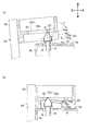
本実施形態では、前記したように、発泡管理冶具40に位置決め部材42を取り付け、また給湯管14に栓体50や抜け止め冶具70などを取り付けることで、給湯管14の位置ずれを防止する(給湯管14の位置出しを行う)ようにしたものである。以下において、位置決めする際の動作について、図6ないし図8を参照して説明する。図6は、横向きに位置ずれした配管を位置決めする場合の動作説明図であり、(a)は位置決め前、(b)は位置決め途中、(c)は位置決め完了時である。図7は、上下向きに位置ずれした配管を位置決めする場合の動作説明図であり、(a)は位置決め前、(b)は位置決め途中、(c)は位置決め完了時であり、図8は、前後方向に位置ずれした配管を位置決めする場合の動作説明図であり、(a)は位置決め前、(b)は位置決め途中、(c)は位置決め完了時である。なお、図6は、給湯管14が横向きのうちの右向きとなった場合、図7は、給湯管14が上下向きのうちの上向きとなった場合、図8は、給湯管14が前後方向のうちの前方に位置する場合の位置決め(位置出し)について説明する。   In the present embodiment, as described above, the positioning member 42 is attached to the foam management jig 40, and the stopper 50, the retaining jig 70, and the like are attached to the hot water supply pipe 14, thereby preventing the misalignment of the hot water supply pipe 14 ( The hot water supply pipe 14 is positioned). Hereinafter, the positioning operation will be described with reference to FIGS. FIGS. 6A and 6B are operation explanatory diagrams in the case of positioning a pipe that is displaced laterally, in which FIG. 6A is before positioning, FIG. 6B is during positioning, and FIG. 6C is when positioning is completed. FIG. 7 is an operation explanatory diagram when positioning a pipe displaced in the vertical direction, (a) before positioning, (b) during positioning, (c) when positioning is completed, and FIG. It is operation | movement explanatory drawing when positioning the pipe | tube shifted in the front-back direction, (a) is before positioning, (b) is in the middle of positioning, (c) is the time of positioning completion. 6 shows a case where the hot water supply pipe 14 is turned rightward in the horizontal direction, FIG. 7 shows a case where the hot water supply pipe 14 is turned upward in the vertical direction, and FIG. Positioning (positioning) in the case of being located in front will be described.

図6(a)に示すように、発泡管理冶具40には、外箱3の側板3bに対応する板材43に位置決め部材42が取り付けられている。この板材43は、他の板材(背板3c(図3参照)に対応する板材)に回動可能に支持されており、板材43の回動動作とともに位置決め部材42が回動動作するように構成されている。また、栓体50と抜け止め冶具70が取り付けられた配管14の軸方向O1は、貫通孔3tの軸方向O2に対して右側に傾いている。また、抜け止め冶具70は、短板部3a3および傾斜板部3a5から離間している。発泡管理冶具40の板材43が回動しながら動作することで、位置決め部材42の長孔42aが栓体50に近づくようになっている。   As shown in FIG. 6A, in the foam management jig 40, a positioning member 42 is attached to a plate material 43 corresponding to the side plate 3 b of the outer box 3. The plate member 43 is rotatably supported by another plate member (a plate member corresponding to the back plate 3c (see FIG. 3)), and the positioning member 42 is configured to rotate along with the rotation of the plate member 43. Has been. In addition, the axial direction O1 of the pipe 14 to which the plug body 50 and the retaining jig 70 are attached is inclined to the right side with respect to the axial direction O2 of the through hole 3t. Further, the retaining jig 70 is separated from the short plate portion 3a3 and the inclined plate portion 3a5. The long hole 42a of the positioning member 42 approaches the plug body 50 by the plate material 43 of the foam management jig 40 operating while rotating.

図6(b)に示すように、発泡管理冶具40の板材43が回動して位置決め部材42が図6(a)の状態からさらに回動すると、長孔42a内に円錐部50aの先端が位置する。そして、位置決め部材42は、円錐部50aの先端が長孔42a内を左端から右端に位置するように移動する(回動する)。このように、回動する板材43に位置決め部材42を取り付ける場合には、位置決め部材42が回動する方向(左右方向)に沿う長孔42aとすることにより、円錐部50aを長孔42aに案内できるようになる。なお、長孔42aの左端は、円錐部50aを長孔42a内に挿入できる位置であればよい。長孔42aの右端は、給湯管14の軸方向O1と貫通孔3tの軸方向O2とを一致させることが可能な位置に設定される。   As shown in FIG. 6 (b), when the plate member 43 of the foam management jig 40 is rotated and the positioning member 42 is further rotated from the state shown in FIG. 6 (a), the tip of the conical portion 50a is placed in the long hole 42a. To position. The positioning member 42 moves (rotates) so that the tip of the conical portion 50a is positioned from the left end to the right end in the long hole 42a. As described above, when the positioning member 42 is attached to the rotating plate member 43, the conical portion 50a is guided to the long hole 42a by forming the long hole 42a along the direction (left-right direction) in which the positioning member 42 rotates. become able to. In addition, the left end of the long hole 42a should just be a position which can insert the cone part 50a in the long hole 42a. The right end of the long hole 42a is set at a position where the axial direction O1 of the hot water supply pipe 14 and the axial direction O2 of the through hole 3t can be matched.

そして、図6(c)に示すように、発泡管理冶具40の板材43が回動して位置決め部材42が図6(b)の状態からさらに回動すると、長孔42aの端部42a1が円錐部50aに当接する。このとき、発泡管理冶具40が回動する際の動作力Fによって、長孔42aの端部42a1によって円錐部50aが左側に押圧される。これにより、配管14の軸方向O1の向きが修正され、給湯管14の軸方向O1が貫通孔3tの軸方向O2に一致する。また、給湯管14の向きが修正されることで、抜け止め冶具70の傾斜面72が外箱3の傾斜板部3a5の壁面に面接触し、給湯管14が左側に傾くのを防止できる。このようにして、給湯管14の横向き(右向き)の位置ずれを防止できる。なお、抜け止め冶具70の傾斜面72が傾斜板部3a5に当接するように構成されていることで、発泡圧力によって給湯管14の軸方向O1の向きが左向きとなることが防止される。   Then, as shown in FIG. 6C, when the plate member 43 of the foam management jig 40 is rotated and the positioning member 42 is further rotated from the state of FIG. 6B, the end 42a1 of the long hole 42a is conical. It contacts the part 50a. At this time, the conical portion 50a is pressed to the left by the end portion 42a1 of the long hole 42a by the operating force F when the foam management jig 40 rotates. Thereby, the direction of the axial direction O1 of the piping 14 is corrected, and the axial direction O1 of the hot water supply pipe 14 coincides with the axial direction O2 of the through hole 3t. Further, by correcting the direction of the hot water supply pipe 14, it is possible to prevent the inclined surface 72 of the retaining jig 70 from coming into surface contact with the wall surface of the inclined plate portion 3a5 of the outer box 3, and the hot water supply pipe 14 from being inclined to the left side. In this way, it is possible to prevent a lateral (rightward) position shift of the hot water supply pipe 14. In addition, since the inclined surface 72 of the retaining jig 70 is configured to contact the inclined plate portion 3a5, the axial direction O1 of the hot water supply pipe 14 is prevented from being leftward due to the foaming pressure.

図7(a)は、給湯管14の軸方向O3が、貫通孔3tの軸方向O2に対して上側(図示左側)に傾いている場合である。また、抜け止め冶具70が、短板部3a3から離間している。   FIG. 7A shows a case where the axial direction O3 of the hot water supply pipe 14 is inclined upward (left side in the drawing) with respect to the axial direction O2 of the through hole 3t. Further, the retaining jig 70 is separated from the short plate portion 3a3.

図7(b)に示すように、発泡管理冶具40の板材43(図6参照)が回動しながら動作することで、長孔42a内に円錐部50aの先端が位置するように位置決め部材42が回動し、円錐部50aの先端が長孔42aの端部42a2に接触する。このように、長孔42aが前方から後方に向けて末広がり形状となるように構成されることで、給湯管14の軸方向O3が傾いている場合であっても、円錐部50aを長孔42a内に案内することが可能になる。   As shown in FIG. 7 (b), the plate member 43 (see FIG. 6) of the foam management jig 40 operates while rotating so that the positioning member 42 is positioned so that the tip of the conical portion 50a is positioned in the long hole 42a. Rotates, and the tip of the conical part 50a contacts the end part 42a2 of the long hole 42a. In this way, the long hole 42a is configured so as to have a divergent shape from the front to the rear, so that the conical portion 50a is formed in the long hole 42a even when the axial direction O3 of the hot water supply pipe 14 is inclined. It becomes possible to guide in.

そして、図7(c)に示すように、発泡管理冶具40の板材43(図6参照)が回動して位置決め部材42が図7(b)の状態からさらに回動すると、そのときの回動力(移動力F)によって円錐部50aに長孔42aの上下(図示左右)の端部42a2、42a3が当接する。これにより、給湯管14の軸方向O3の上下方向の傾きが修正され、軸方向O3が貫通孔3tの軸方向O2に一致する。   Then, as shown in FIG. 7C, when the plate member 43 (see FIG. 6) of the foam management jig 40 is rotated and the positioning member 42 is further rotated from the state of FIG. 7B, the rotation at that time is performed. The upper and lower ends 42a2 and 42a3 of the elongated hole 42a abut against the conical portion 50a by the power (moving force F). Thereby, the vertical inclination of the axial direction O3 of the hot water supply pipe 14 is corrected, and the axial direction O3 coincides with the axial direction O2 of the through hole 3t.

図8(a)は、給湯管14が前後方向の前方に飛び出ている場合である。また、抜け止め冶具70は、短板部3a3から離間している。なお、説明を簡略化するため、給湯管14の軸方向は、貫通孔3tの軸方向と一致している場合を例に挙げて説明する。   FIG. 8A shows a case where the hot water supply pipe 14 protrudes forward in the front-rear direction. Further, the retaining jig 70 is separated from the short plate portion 3a3. In addition, in order to simplify description, the case where the axial direction of the hot water supply pipe 14 is coincident with the axial direction of the through hole 3t will be described as an example.

図8(b)に示すように、発泡管理冶具40の板材43(図6参照)が回動しながら動作することで、抜け止め冶具70が短板部3a3には接しない状態で、円錐部50aに長孔42aの上下の端部42a2,42a3が当接する。   As shown in FIG. 8B, the plate member 43 (see FIG. 6) of the foam management jig 40 operates while rotating so that the retaining jig 70 is not in contact with the short plate portion 3a3. The upper and lower end portions 42a2 and 42a3 of the long hole 42a come into contact with 50a.

そして、図8(c)に示すように、発泡管理冶具40の板材43(図6参照)が回転して位置決め部材42が図8(b)の状態からさらに回動すると、そのときの回動力(動作力F)によって円錐部50aが位置決め部材42の長孔42aによって後方(図示下側)に押圧されることで、給湯管14が外箱3内に押し込まれ、給湯管14の前後方向の位置が予め決められた位置に修正される。   Then, as shown in FIG. 8C, when the plate member 43 (see FIG. 6) of the foam management jig 40 rotates and the positioning member 42 further rotates from the state of FIG. (Operational force F) causes the conical portion 50a to be pushed rearward (lower side in the figure) by the long hole 42a of the positioning member 42, so that the hot water supply pipe 14 is pushed into the outer casing 3, and the hot water supply pipe 14 is The position is corrected to a predetermined position.

このようにして、給湯管14が発泡管理冶具40の位置決め部材42によって位置決めされた状態において、外箱3と貯湯タンク2との間の隙間に発泡断熱材6(発泡液)を注入して発泡させる(図3参照)。そして、給湯管14に取り付けられた栓体50および抜け止め部材70を取り外し、また貫通孔3tと給湯管14との隙間を密閉し、給湯管14に他の配管や弁などを取り付け、外箱3に配管カバー3sを取り付ける。   In this way, in the state where the hot water supply pipe 14 is positioned by the positioning member 42 of the foam management jig 40, the foam insulation material 6 (foaming liquid) is injected into the gap between the outer box 3 and the hot water storage tank 2 and foamed. (See FIG. 3). Then, the plug body 50 and the retaining member 70 attached to the hot water supply pipe 14 are removed, the gap between the through hole 3t and the hot water supply pipe 14 is sealed, and other piping or valves are attached to the hot water supply pipe 14, and the outer box A pipe cover 3 s is attached to 3.

以上説明したように、本実施形態の貯湯タンクユニット1では、発泡管理冶具40に給湯管14を位置決めする位置決め部材42が設けられている。これにより、外箱3内に給湯管14を位置決めして固定する固定部材を設ける必要がなくなり、簡単な構成で給湯管14を位置決めすることが可能になる。また、固定部材が不要になることで、外箱3内の構造が複雑になるのを防止でき、給湯管14の周囲を含めて貯湯タンク2と外箱3との間の隙間全体に発泡断熱材6(発泡後)を容易に行き渡らせることができる。   As described above, in the hot water storage tank unit 1 of the present embodiment, the positioning member 42 that positions the hot water supply pipe 14 in the foam management jig 40 is provided. Thereby, it is not necessary to provide a fixing member for positioning and fixing the hot water supply pipe 14 in the outer box 3, and the hot water supply pipe 14 can be positioned with a simple configuration. Further, since the fixing member is not required, the structure in the outer box 3 can be prevented from becoming complicated, and foam insulation is provided in the entire gap between the hot water storage tank 2 and the outer box 3 including the periphery of the hot water supply pipe 14. The material 6 (after foaming) can be easily distributed.

また、本実施形態では、発泡管理冶具40の板材43を外箱3に取り付ける際の移動力(動作力F)によって給湯管14が位置決めされる。これにより、発泡管理冶具40の取り付けと同時に位置決めが完了するので、給湯管14を迅速に位置決めすることができ、その後の発泡断熱材6の発泡液の注入工程および発泡工程に直ちに移行することが可能になる。   In the present embodiment, the hot water supply pipe 14 is positioned by the moving force (operating force F) when the plate material 43 of the foam management jig 40 is attached to the outer box 3. Thereby, since positioning is completed simultaneously with the installation of the foam management jig 40, the hot water supply pipe 14 can be quickly positioned, and the process can immediately shift to the foaming liquid injection process and the foaming process of the foam insulation material 6 thereafter. It becomes possible.

また、本実施形態によれば、給湯管14の接続口14dに、接続口14dを閉塞する円錐部50aを有する栓体50を取り付けて、この円錐部50aを介して給湯管14を位置決めするようにしたので、給湯管14の位置決めとともに、貯湯タンク2内に空気圧をかけた状態で発泡断熱材6を構成できるので、発泡圧力による貯湯タンク2の変形(へこみ)も防止することが可能になる。   Further, according to the present embodiment, the plug body 50 having the conical portion 50a for closing the connection port 14d is attached to the connection port 14d of the hot water supply tube 14, and the hot water supply tube 14 is positioned through the conical portion 50a. Since the foamed heat insulating material 6 can be configured while the hot water supply pipe 14 is positioned and the air pressure is applied to the hot water storage tank 2, the hot water storage tank 2 can be prevented from being deformed (dented) due to the foaming pressure. .

また、本実施形態によれば、給湯管14に栓体50が抜け出るのを防止する抜け止め冶具70を取り付け、この抜け止め冶具70の傾斜板部3a5に外箱3を当接させて給湯管14の左右方向の位置決めを行うことで、外箱3に抜け止め冶具70を当接させる当接部を新たに設ける必要がなくなる。   In addition, according to the present embodiment, the retaining jig 70 for preventing the plug body 50 from coming out is attached to the hot water supply pipe 14, and the outer box 3 is brought into contact with the inclined plate portion 3 a 5 of the retaining jig 70 so that the hot water supply pipe By positioning 14 in the left-right direction, there is no need to newly provide an abutting portion for abutting the retaining jig 70 against the outer box 3.

(第2実施形態)
図9は、第2実施形態に係る貯湯タンクユニットにおける配管の位置決め方法を説明する動作説明図であり、(a)は位置決め前、(b)は位置決め完了時である。第2実施形態では、外箱3に替えて外箱3Aとし、抜け止め冶具70に替えて抜け止め冶具70Aとしたものである。その他の構成については、第1実施形態と同様に構成されている。また、図9では、給湯管14が右向き(横向き)の場合のみを例に挙げて説明するが、上下方向に位置ずれしている場合、前後方向に位置ずれしている場合などその他の位置決め方法については、第1実施形態と同様にして位置決めされるものとして説明を省略する。
(Second Embodiment)
FIG. 9 is an operation explanatory view for explaining a piping positioning method in the hot water storage tank unit according to the second embodiment, where (a) is before positioning and (b) is when positioning is completed. In the second embodiment, the outer box 3 is replaced with an outer box 3A, and the retaining jig 70 is replaced with a retaining jig 70A. About another structure, it is comprised similarly to 1st Embodiment. In FIG. 9, only the case where the hot water supply pipe 14 is facing right (sideways) will be described as an example. However, when the position is shifted in the vertical direction, the position is shifted in the front-rear direction, or other positioning methods. The description will be omitted because it is positioned in the same manner as in the first embodiment.

ずなわち、図9(a)に示すように、外箱3Aは、第1実施形態のように中央部が前方に突出する山型ではなく、前板3aが平坦な板状に形成されたものである。また、外箱3Aには、給湯管14が挿通される貫通孔3tよりも左側に、突起部3f(当接部)が形成されている。   In other words, as shown in FIG. 9A, the outer box 3A is not a mountain shape with the center portion protruding forward as in the first embodiment, but the front plate 3a is formed in a flat plate shape. Is. In addition, a projection 3f (contact portion) is formed on the outer box 3A on the left side of the through hole 3t through which the hot water supply pipe 14 is inserted.

抜け止め冶具70Aは、第1実施形態の抜け止め冶具70のように傾斜面72を有しない四角ブロック状に形成されたものである。すなわち、抜け止め冶具70の左側面70bは、前板3aの壁面(表面)に対して直交する面である。なお、本実施形態では、左側面70bが前板3aの壁面に直交する面である場合を例に挙げて説明したが、当接部に当接できるものであれば、左側面70bの向きや形状は特に限定されるものではなく、また当接部についても形状などは特に限定されるものではない。   The retaining jig 70A is formed in a square block shape that does not have the inclined surface 72 as in the retaining jig 70 of the first embodiment. That is, the left side surface 70b of the retaining jig 70 is a surface orthogonal to the wall surface (surface) of the front plate 3a. In the present embodiment, the case where the left side surface 70b is a surface orthogonal to the wall surface of the front plate 3a has been described as an example. However, if the left side surface 70b can contact the contact portion, the orientation of the left side surface 70b The shape is not particularly limited, and the shape of the contact portion is not particularly limited.

図9(a)では、給湯管14の軸方向O1が貫通孔3tの軸方向O2に対して右方向(図示左方向)に傾斜し、また抜け止め冶具70Aの左側面70aが突起部3fから離間した状態である。また、抜け止め冶具70Aの下面は、前板3aの表面から離間している。   In FIG. 9 (a), the axial direction O1 of the hot water supply pipe 14 is inclined rightward (leftward in the drawing) with respect to the axial direction O2 of the through hole 3t, and the left side surface 70a of the retaining jig 70A extends from the protrusion 3f. It is in a separated state. Further, the lower surface of the retaining jig 70A is separated from the surface of the front plate 3a.

第2実施形態では、第1実施形態と同様にして、発泡管理冶具40の板材43が回動して、位置決め部材42が回動することで、右端において長孔42a内の円錐部50aの先端が位置し、円錐部50aの先端が長孔42a内を左端から右端に移動するように長孔42aが回動する。   In the second embodiment, as in the first embodiment, the plate member 43 of the foam management jig 40 rotates and the positioning member 42 rotates, so that the tip of the conical portion 50a in the long hole 42a is rotated at the right end. , And the long hole 42a rotates so that the tip of the conical portion 50a moves from the left end to the right end in the long hole 42a.

そして、図9(b)に示すように、円錐部50aに長孔42aの端部42a1が当接する。このとき、発泡管理冶具40(板材43)が回動する際の動作力Fによって、長孔42aの端部42a1によって円錐部50aが左側に押圧される。これにより、配管14の軸方向O1の向きが修正され、給湯管14の軸方向O1が貫通孔3tの軸方向O2に一致する。また、給湯管14の向きが修正されることで、抜け止め冶具70Aの左側面70bが外箱3Aの突起部3fに当接し、給湯管14が左方向に移動し過ぎるのを防止できる。このようにして、給湯管14の横向き(右向き)の位置ずれを防止できる。なお、抜け止め冶具70Aの左側面70bが突起部3fに当接するように構成されていることで、発泡圧力によって給湯管14の軸方向O1の向きが左向きとなることが防止される。   And as shown in FIG.9 (b), the edge part 42a1 of the elongate hole 42a contact | abuts to the cone part 50a. At this time, the conical portion 50a is pressed to the left by the end portion 42a1 of the long hole 42a by the operating force F when the foam management jig 40 (plate material 43) rotates. Thereby, the direction of the axial direction O1 of the piping 14 is corrected, and the axial direction O1 of the hot water supply pipe 14 coincides with the axial direction O2 of the through hole 3t. Further, by correcting the direction of the hot water supply pipe 14, it is possible to prevent the left side surface 70b of the retaining jig 70A from coming into contact with the protruding portion 3f of the outer box 3A, and the hot water supply pipe 14 from moving too far to the left. In this way, it is possible to prevent a lateral (rightward) position shift of the hot water supply pipe 14. Note that the left side surface 70b of the retaining jig 70A is configured to abut against the protruding portion 3f, thereby preventing the hot water supply pipe 14 from being directed leftward due to the foaming pressure.

第2実施形態によれば、第1実施形態と同様に、簡単な構成で給湯管14を位置決めすることが可能になり、給湯管14を迅速に位置決めすることができる。さらに、第2実施形態によれば、給湯管14の位置決めとともに、貯湯タンク2内に空気圧をかけた状態で発泡断熱材6(発泡液)を発泡させることができるので発泡圧力による貯湯タンク2の変形も防止することが可能になる。また、第2実施形態によれば、突起部3fを設けることで、横断面視四角形状の外箱3Aを備えた貯湯タンクユニットにも適用することができる。   According to the second embodiment, similarly to the first embodiment, the hot water supply pipe 14 can be positioned with a simple configuration, and the hot water supply pipe 14 can be positioned quickly. Furthermore, according to 2nd Embodiment, since the foaming heat insulating material 6 (foaming liquid) can be foamed in the state which applied the air pressure in the hot water storage tank 2 with positioning of the hot water supply pipe 14, the hot water storage tank 2 of foaming pressure is used. Deformation can also be prevented. Moreover, according to 2nd Embodiment, it can apply also to the hot water storage tank unit provided with 3 A of outer boxes 3A of cross-sectional view square shape by providing the projection part 3f.

なお、本発明は、前記した実施形態に限定されるものではなく、本発明の趣旨を逸脱しない範囲において種々変更することができる。例えば、前記した実施形態では、発泡管理冶具40を外箱3に設置する際の動作力Fによって給湯管14(配管)を位置決めする場合を例に挙げて説明したが、これに限定されるものではなく、発泡管理冶具40の動作力によらずに配管を位置決めする構成であってもよい。   In addition, this invention is not limited to above-described embodiment, In the range which does not deviate from the meaning of this invention, it can change variously. For example, in the above-described embodiment, the case where the hot water supply pipe 14 (pipe) is positioned by the operating force F when the foam management jig 40 is installed in the outer box 3 has been described as an example, but the present invention is not limited thereto. Instead, the configuration may be such that the piping is positioned without depending on the operating force of the foam management jig 40.

また、本実施形態では、発泡管理冶具40の板材43が回動可能に支持されて、位置決め部材42が回動する動作によって配管が位置決めされる場合を例に挙げて説明したが、前後方向に動作する発泡管理冶具40の板材によって配管が位置決めされる構成であってもよい。この場合には、長孔42aではなく、縦断面視において円錐台形状の孔によって配管を位置決めすることができる。   Further, in the present embodiment, the case where the plate member 43 of the foam management jig 40 is rotatably supported and the pipe is positioned by the operation of rotating the positioning member 42 has been described as an example. The pipe may be positioned by the plate material of the foam management jig 40 that operates. In this case, the pipe can be positioned not by the long hole 42a but by the truncated cone-shaped hole in the longitudinal sectional view.

また、本実施形態では、発泡管理冶具40の板材43に位置決め部材42を取り付けた場合を例に挙げて説明したが、前板3aに対応する発泡管理冶具40の板材に位置決め部材を取り付ける構成であってもよい。   Further, in the present embodiment, the case where the positioning member 42 is attached to the plate member 43 of the foam management jig 40 has been described as an example. However, the positioning member is attached to the plate member of the foam management jig 40 corresponding to the front plate 3a. There may be.

なお、前記実施形態では、剛体で形成された金属製の給湯管14(配管)を例に挙げて説明したが、金属製の蛇腹形状の配管としてもよい。これによれば、発泡圧力によって配管(給湯管14など)の向きが位置ずれしたとしても、発泡後に上下左右の所望の向きに配管の接続口を変更することができる。   In the above embodiment, the metal hot water supply pipe 14 (pipe) formed of a rigid body has been described as an example. However, a metal bellows-shaped pipe may be used. According to this, even if the direction of the pipe (hot water supply pipe 14 or the like) is displaced due to the foaming pressure, the connection port of the pipe can be changed to a desired direction in the vertical and horizontal directions after foaming.

1 貯湯タンクユニット
2 貯湯タンク
3,3A 外箱
3a 前板
3a3 短板部
3a5 傾斜板部
3b 側板
3c 後板
3d 上板
3e 底板
3f 突起部
3t 貫通孔
6 発泡断熱材
11 給水管(配管)
12 入水管(配管)
13 出湯管(配管)
14 給湯管(配管)
40 発泡管理冶具
42 位置決め部材
42a 長孔
43 板材
50 栓体
50a 円錐部
70 抜け止め冶具(冶具)
F 動作力
DESCRIPTION OF SYMBOLS 1 Hot water storage tank unit 2 Hot water storage tank 3, 3A Outer box 3a Front plate 3a3 Short plate part 3a5 Inclined plate part 3b Side plate 3c Rear plate 3d Top plate 3e Bottom plate 3f Protrusion part 3t Through-hole 6 Foam insulation 11 Water supply pipe (pipe)
12 Inlet pipe (piping)
13 Hot water pipe (piping)
14 Hot water supply pipe (pipe)
40 Foam Management Jig 42 Positioning Member 42a Long Hole 43 Plate Material 50 Plug Body 50a Cone 70 Retaining Jig (Jig)
F Power

Claims (2)

貯湯タンクと、
前記貯湯タンクを収容する外箱と、
前記貯湯タンクと接続され、前記外箱の外部に引き出される配管と、
前記外箱と前記貯湯タンクとの間に満たされている発泡断熱材と、を備え、
前記外箱には、前記発泡断熱材を設ける際に発泡液が発泡する際の圧力によって当該外箱が変形するのを防止する発泡管理冶具が当該外箱のそれぞれの面に接する板材を備えて当該外箱の周囲全体を取り囲むように取り付けられ、
前記発泡管理冶具には、回動しながら動作する前記板材に前記配管を位置決めする位置決め部材が設けられ
前記配管の先端部は、前記外箱に形成された貫通孔から突出し、
前記配管の先端部の接続口には、当該接続口を閉塞する円錐部を有する栓体が取り付けられ、
前記位置決め部材には、当該位置決め部材の回動方向に沿って形成され、かつ、前記円錐部を通過できない幅の長孔が形成され、
前記長孔の長手方向の両端部および前記幅方向の両端部は、前記円錐部の斜面と平行な角度で形成され、
前記位置決め部材は、前記発泡管理冶具の板材を回動させて前記外箱に取り付ける際の動作力を用いて、前記端部を前記円錐部の斜面に当接させて当該端部によって当該斜面が押圧されることで、前記配管の軸方向と前記貫通孔の軸方向とが一致するように前記配管を位置決めする部材であることを特徴とする貯湯タンクユニット。
A hot water storage tank,
An outer box containing the hot water storage tank;
A pipe connected to the hot water storage tank and drawn out of the outer box;
A foam heat insulating material filled between the outer box and the hot water storage tank,
Said outer box is provided with a plate in which the foaming management jig which the outer packaging in providing the foam insulation by pressure when foamed liquid foams is prevented from being deformed in contact with the respective surfaces of the outer box Attached to surround the entire periphery of the outer box ,
The foam management jig is provided with a positioning member for positioning the pipe on the plate material that operates while rotating ,
The tip of the pipe protrudes from a through hole formed in the outer box,
A plug body having a conical portion for closing the connection port is attached to the connection port at the tip of the pipe,
The positioning member is formed along a rotation direction of the positioning member, and a long hole having a width that cannot pass through the conical portion is formed.
Both ends in the longitudinal direction of the long hole and both ends in the width direction are formed at an angle parallel to the slope of the conical portion,
The positioning member rotates the plate of the foam management jig and attaches it to the outer box, using the operating force to bring the end into contact with the inclined surface of the conical portion, so that the inclined surface is caused by the end. The hot water storage tank unit is a member that positions the pipe so that the axial direction of the pipe and the axial direction of the through hole coincide with each other when pressed .
前記配管には、前記外箱に当接して当該配管を位置決めする冶具が取り付けられていることを特徴とする請求項1に記載の貯湯タンクユニット。 The pipe, the hot water storage tank unit according to claim 1, characterized in that the jig to position the contact with the pipe in the outer box is mounted.
JP2014170969A 2014-08-25 2014-08-25 Hot water storage tank unit Active JP6296551B2 (en)

Priority Applications (1)

Application Number Priority Date Filing Date Title
JP2014170969A JP6296551B2 (en) 2014-08-25 2014-08-25 Hot water storage tank unit

Applications Claiming Priority (1)

Application Number Priority Date Filing Date Title
JP2014170969A JP6296551B2 (en) 2014-08-25 2014-08-25 Hot water storage tank unit

Publications (3)

Publication Number Publication Date
JP2016044921A JP2016044921A (en) 2016-04-04
JP2016044921A5 JP2016044921A5 (en) 2016-10-27
JP6296551B2 true JP6296551B2 (en) 2018-03-20

Family

ID=55635643

Family Applications (1)

Application Number Title Priority Date Filing Date
JP2014170969A Active JP6296551B2 (en) 2014-08-25 2014-08-25 Hot water storage tank unit

Country Status (1)

Country Link
JP (1) JP6296551B2 (en)

Family Cites Families (9)

* Cited by examiner, † Cited by third party
Publication number Priority date Publication date Assignee Title
JPS50106164U (en) * 1974-02-06 1975-09-01
US4477399A (en) * 1982-06-16 1984-10-16 Gsw Inc. Method and apparatus for manufacturing a foam insulated water heater
JPS6124963A (en) * 1984-07-12 1986-02-03 三菱電機株式会社 Manufacture of refrigerator
JPS6127446A (en) * 1984-07-18 1986-02-06 Takara Standard Kk Electric hot water apparatus
JPH0217298A (en) * 1988-07-05 1990-01-22 Sanyo Electric Co Ltd Manufacture of heat insulating pipe
US4992223A (en) * 1989-08-11 1991-02-12 Soltech, Inc. Water heater construction and method of making same
US5292464A (en) * 1992-08-25 1994-03-08 Rheem Manufacturing Company Method of insulating a water heater and preventing flash using a foam stop
JP2003065483A (en) * 2001-08-29 2003-03-05 Shiyouji Ishida Method of manufacturing sound-deadening joint, and sound-deadening joint
JP2013245918A (en) * 2012-05-29 2013-12-09 Sharp Corp Heat insulating box body, method of manufacturing the same, and refrigerator

Also Published As

Publication number Publication date
JP2016044921A (en) 2016-04-04

Similar Documents

Publication Publication Date Title
JP6296551B2 (en) Hot water storage tank unit
US10094592B2 (en) Water heater with thermal break
JP2015178951A (en) Hot water storage tank unit and manufacturing method of the same
JP5720237B2 (en) Heat pump heat source machine
JP6314061B2 (en) Hot water storage tank unit
JP2017032176A (en) Water heater and manufacturing method of the same
WO2018066101A1 (en) Refrigerator
JP6324826B2 (en) Hot water storage tank unit
JP5859617B1 (en) Hot water storage tank unit
JP6524301B2 (en) Hot water storage tank unit
JP6301221B2 (en) Hot water storage tank unit
JP6435223B2 (en) Hot water storage tank unit
JP2018091562A (en) Carburetor and manufacturing method thereof
JP6405144B2 (en) Hot water storage tank unit
JP5837243B1 (en) Hot water storage tank unit
JP6314045B2 (en) Hot water storage tank unit
KR100420366B1 (en) Structure of dispenser portion for refrigerator
KR101819280B1 (en) Test storage tank
JP6557528B2 (en) Hot water storage tank unit
JP6310365B2 (en) Hot water storage tank unit
JP6556564B2 (en) Hot water storage tank unit
JP6596529B2 (en) Hot water storage tank unit
CN105987510B (en) Heat accumulation water pot unit
JP6556565B2 (en) Hot water storage tank unit
JP6218654B2 (en) Hot water storage tank unit and manufacturing method thereof

Legal Events

Date Code Title Description
A521 Written amendment

Free format text: JAPANESE INTERMEDIATE CODE: A523

Effective date: 20160908

A621 Written request for application examination

Free format text: JAPANESE INTERMEDIATE CODE: A621

Effective date: 20160908

A977 Report on retrieval

Free format text: JAPANESE INTERMEDIATE CODE: A971007

Effective date: 20170726

A131 Notification of reasons for refusal

Free format text: JAPANESE INTERMEDIATE CODE: A131

Effective date: 20170801

A521 Written amendment

Free format text: JAPANESE INTERMEDIATE CODE: A523

Effective date: 20170915

TRDD Decision of grant or rejection written
A01 Written decision to grant a patent or to grant a registration (utility model)

Free format text: JAPANESE INTERMEDIATE CODE: A01

Effective date: 20180206

A61 First payment of annual fees (during grant procedure)

Free format text: JAPANESE INTERMEDIATE CODE: A61

Effective date: 20180215

R150 Certificate of patent or registration of utility model

Ref document number: 6296551

Country of ref document: JP

Free format text: JAPANESE INTERMEDIATE CODE: R150

S533 Written request for registration of change of name

Free format text: JAPANESE INTERMEDIATE CODE: R313533

R350 Written notification of registration of transfer

Free format text: JAPANESE INTERMEDIATE CODE: R350