JP6288985B2 - Lithographic apparatus and article manufacturing method - Google Patents
Lithographic apparatus and article manufacturing method Download PDFInfo
- Publication number
- JP6288985B2 JP6288985B2 JP2013168335A JP2013168335A JP6288985B2 JP 6288985 B2 JP6288985 B2 JP 6288985B2 JP 2013168335 A JP2013168335 A JP 2013168335A JP 2013168335 A JP2013168335 A JP 2013168335A JP 6288985 B2 JP6288985 B2 JP 6288985B2
- Authority
- JP
- Japan
- Prior art keywords
- peripheral
- pattern
- area
- shot
- region
- Prior art date
- Legal status (The legal status is an assumption and is not a legal conclusion. Google has not performed a legal analysis and makes no representation as to the accuracy of the status listed.)
- Active
Links
Images


Classifications
-
- G—PHYSICS
- G03—PHOTOGRAPHY; CINEMATOGRAPHY; ANALOGOUS TECHNIQUES USING WAVES OTHER THAN OPTICAL WAVES; ELECTROGRAPHY; HOLOGRAPHY
- G03F—PHOTOMECHANICAL PRODUCTION OF TEXTURED OR PATTERNED SURFACES, e.g. FOR PRINTING, FOR PROCESSING OF SEMICONDUCTOR DEVICES; MATERIALS THEREFOR; ORIGINALS THEREFOR; APPARATUS SPECIALLY ADAPTED THEREFOR
- G03F7/00—Photomechanical, e.g. photolithographic, production of textured or patterned surfaces, e.g. printing surfaces; Materials therefor, e.g. comprising photoresists; Apparatus specially adapted therefor
- G03F7/70—Microphotolithographic exposure; Apparatus therefor
- G03F7/70058—Mask illumination systems
-
- G—PHYSICS
- G03—PHOTOGRAPHY; CINEMATOGRAPHY; ANALOGOUS TECHNIQUES USING WAVES OTHER THAN OPTICAL WAVES; ELECTROGRAPHY; HOLOGRAPHY
- G03F—PHOTOMECHANICAL PRODUCTION OF TEXTURED OR PATTERNED SURFACES, e.g. FOR PRINTING, FOR PROCESSING OF SEMICONDUCTOR DEVICES; MATERIALS THEREFOR; ORIGINALS THEREFOR; APPARATUS SPECIALLY ADAPTED THEREFOR
- G03F7/00—Photomechanical, e.g. photolithographic, production of textured or patterned surfaces, e.g. printing surfaces; Materials therefor, e.g. comprising photoresists; Apparatus specially adapted therefor
- G03F7/70—Microphotolithographic exposure; Apparatus therefor
- G03F7/70483—Information management; Active and passive control; Testing; Wafer monitoring, e.g. pattern monitoring
- G03F7/7055—Exposure light control in all parts of the microlithographic apparatus, e.g. pulse length control or light interruption
Description
本発明は、リソグラフィ装置、および物品の製造方法に関する。 The present invention relates to a lithographic apparatus and a method for manufacturing an article.
近年、半導体デバイスの実装として、フリップチップによる実装が採用されるケースが増えてきている。フリップチップによる実装に対応した半導体デバイスの製造工程には、はんだボールや再配線をデバイス上に形成する工程が含まれる。はんだボールや再配線を形成する方法の1つとしてメッキによる形成法がある。メッキによって、はんだボールや再配線を形成するためには、ウェーハ(基板とよばれる場合もある)上に形成された導電性膜とメッキ装置の電極を接触させて導通を取る必要がある。そこで、導電性膜の上に形成されているレジスト膜をウェーハの周辺部分で剥離して、導電性膜とメッキ装置の電極の導通をとる方法が特許文献1で提案されている。 In recent years, flip chip mounting is increasingly used as semiconductor device mounting. A manufacturing process of a semiconductor device corresponding to mounting by flip chip includes a process of forming solder balls and rewiring on the device. One method for forming solder balls and rewiring is by plating. In order to form solder balls and rewiring by plating, it is necessary to bring a conductive film formed on a wafer (sometimes referred to as a substrate) into contact with an electrode of a plating apparatus. In view of this, Patent Document 1 proposes a method in which the resist film formed on the conductive film is peeled off at the peripheral portion of the wafer and the conductive film and the electrode of the plating apparatus are made conductive.
レジストがネガティブタイプ(ネガレジスト)の場合には、露光中にウェーハ周辺部に光があたらないようにすればよく、ウェーハ上に遮光板を配置して露光する方法が特許文献2で提案されている。
When the resist is a negative type (negative resist), it is only necessary to prevent light from being exposed to the periphery of the wafer during exposure, and
また、円弧を有する遮光板を回転、直線駆動してウェーハの周辺部を遮光する方法が特許文献3で提案されている。
Further,
しかし、特許文献3で記載の遮光板を回転、直線駆動して遮光する方法においては、ケーブルの実装上、もしくは駆動機構の設計上の制約から、遮光板の回転範囲は制限され、回転範囲の制限により生産性が低下する場合が生じ得る。
However, in the method of rotating and linearly driving the light shielding plate described in
さらには、ウェーハを保持しているステージは露光装置の生産性を向上するために、非常に高速駆動が可能である場合が多い。このため、遮光板を回転駆動する駆動機構は非常に高速な駆動機構を採用しなければ、生産性が低下してしまうという課題があった。 Further, the stage holding the wafer can often be driven at a very high speed in order to improve the productivity of the exposure apparatus. For this reason, the drive mechanism that rotationally drives the light shielding plate has a problem in that productivity is reduced unless a very high-speed drive mechanism is employed.
本発明は、例えば、生産性の点で有利なリソグラフィ技術の提供を目的とする。 An object of the present invention is to provide a lithography technique that is advantageous in terms of productivity, for example.
本発明の1つの側面に係るリソグラフィ装置は、基板の複数のショット領域の各々の上の感光材にパターンを転写するリソグラフィ装置であって、前記複数のショット領域は、第1グループの周辺ショット領域および第2グループの周辺ショット領域を含み、前記第1グループの周辺ショット領域は、第1周辺ショット領域と第2周辺ショット領域とを含み、前記第2グループの周辺ショット領域は、前記第1周辺ショット領域の隣に配置された第3周辺ショット領域と、第4周辺ショット領域とを含み、前記リソグラフィ装置は、開口を規定する第1縁および第2縁を有する遮蔽部材を含み、前記第1縁および前記第2縁の一方を含む前記遮蔽部材の遮蔽領域により、パターンの転写のための光が照射されないように、前記基板の周辺領域を遮蔽する遮蔽部と、前記遮蔽部材を回転させる回転機構と、前記遮蔽部材を並進させる並進機構とを含み、パターンを転写すべき対象の周辺ショット領域に応じて前記遮蔽部材による前記基板の遮蔽領域を変更するための駆動機構と、前記第1グループの周辺ショット領域に対してパターンが転写されるときに前記第1縁を含む前記遮蔽領域を用いて前記周辺領域が遮蔽され、前記第2グループの周辺ショット領域に対してパターンが転写されるときに前記第2縁を含む前記遮蔽領域を用いて前記周辺領域が遮蔽される場合に、パターンを転写すべき前記第1グループの周辺ショット領域の各々について前記第1縁を含む前記遮蔽領域を用いて前記周辺領域を遮蔽しながら、前記第1グループの周辺ショット領域に対して、前記第1周辺ショット領域から前記第2周辺ショット領域まで順にパターンが転写され、その後、パターンを転写すべき前記第2グループの周辺ショット領域の各々について前記第2縁を含む前記遮蔽領域を用いて前記周辺領域を遮蔽しながら、前記第2グループの周辺ショット領域に対して、前記第3周辺ショット領域から前記第4周辺ショット領域まで順にパターンが転写されるように前記基板の前記複数のショット領域に対するパターンの転写の順序を決定し、決定した順序に従って前記駆動機構を制御する制御部と、を有することを特徴とする。 A lithographic apparatus according to one aspect of the present invention is a lithographic apparatus for transferring a pattern to a photosensitive material on each of a plurality of shot regions of a substrate, wherein the plurality of shot regions are a first group of peripheral shot regions. And the second group of peripheral shot regions, the first group of peripheral shot regions includes a first peripheral shot region and a second peripheral shot region, and the second group of peripheral shot regions includes the first peripheral shot region. A lithographic apparatus including a shielding member having a first edge and a second edge defining an opening, the third peripheral shot area being disposed adjacent to the shot area; and a fourth peripheral shot area; A peripheral region of the substrate so that light for pattern transfer is not irradiated by the shielding region of the shielding member including one of the edge and the second edge A shielding unit for shielding, and a rotating mechanism for rotating the shielding member, and a translation mechanism to translate the shielding member, the shielding region of the substrate due to the shielding member in accordance with the pattern on the peripheral shot region of the transcription should do target A driving mechanism for changing the pattern, and when the pattern is transferred to the peripheral shot area of the first group, the peripheral area is shielded using the shield area including the first edge, and the second group When the pattern is transferred to the peripheral shot area, the peripheral area is shielded using the shield area including the second edge . For each of the peripheral shot areas of the first group, the first peripheral scene is shielded using the shielding area including the first edge for each. Tsu is patterned in order from the preparative region to the second peripheral shot region transfer, then, each said peripheral region by using the shielding region including the second edge for the peripheral shot region of the second group to be transferred pattern The pattern of the plurality of shot regions of the substrate is transferred so that the pattern is sequentially transferred from the third peripheral shot region to the fourth peripheral shot region with respect to the peripheral shot region of the second group . to determine the order of transfer, and a controller for controlling the drive mechanism in accordance with the determined order, characterized Rukoto to have a.
本発明によれば、例えば、生産性の点で有利なリソグラフィ技術の提供が可能になる。 According to the present invention, for example, it is possible to provide a lithography technique advantageous in terms of productivity.
以下、図面を参照して、本発明の実施形態を例示的に詳しく説明する。ただし、この実施形態に記載されている構成要素はあくまで例示であり、本発明の技術的範囲は、特許請求の範囲によって確定されるのであって、以下の個別の実施形態によって限定されるわけではない。 Hereinafter, exemplary embodiments of the present invention will be described in detail with reference to the drawings. However, the components described in this embodiment are merely examples, and the technical scope of the present invention is determined by the scope of the claims, and is not limited by the following individual embodiments. Absent.
図1は、基板上に塗布された感光性材料にパターン形成を行う実施形態にかかるリソグラフィ装置を示す。基板上の感光材にパターン形成を行うリソグラフィ装置は、基板を遮蔽する遮蔽部と、遮蔽部が有する遮蔽部材による基板の遮蔽領域を変更するための駆動機構と、駆動機構を制御する制御部とを有する。また、リソグラフィ装置は、型により成形された光硬化性の感光材に光を照射する照射系を有する。また、リソグラフィ装置は、原版のパターンを基板に投影する投影系を有する。 FIG. 1 shows a lithographic apparatus according to an embodiment for patterning a photosensitive material applied on a substrate. A lithography apparatus that performs pattern formation on a photosensitive material on a substrate includes a shielding unit that shields the substrate, a driving mechanism for changing a shielding region of the substrate by a shielding member included in the shielding unit, and a control unit that controls the driving mechanism; Have The lithographic apparatus also has an irradiation system for irradiating light onto a photocurable photosensitive material formed by a mold. The lithographic apparatus also includes a projection system that projects the pattern of the original onto the substrate.
遮蔽部は、開口が形成され、且つ、開口を規定する第1縁および第2縁を有する遮蔽部材を含む。 The shielding portion includes a shielding member in which an opening is formed and having a first edge and a second edge that define the opening.
遮蔽部は、基板の周辺領域に対して、第1縁および第2縁の一方を含む遮蔽部材の遮蔽領域により基板を遮蔽する。駆動機構は、遮蔽部材を回転させる回転機構と、遮蔽部材を並進させる並進機構とを含み、回転機構および並進機構のうち少なくともいずれか一方の駆動により遮蔽部材による基板の遮蔽領域を変更する。制御部は、第1縁を含む遮蔽領域を用いて、回転機構の回転範囲の一端の位置に対応する周辺ショット領域から回転範囲の他端の位置に対応する周辺ショット領域まで周辺ショット領域に第1のパターン形成を順次行なうように駆動機構を制御する。第1のパターン形成後、制御部は、第2縁を含む遮蔽領域を用いて、他端の位置に対応する周辺ショット領域から一端の位置に対応する周辺ショット領域まで周辺ショット領域に第2のパターン形成を順次行うように、駆動機構を制御する。 The shielding unit shields the substrate from the peripheral region of the substrate by the shielding region of the shielding member including one of the first edge and the second edge. The drive mechanism includes a rotation mechanism that rotates the shielding member and a translation mechanism that translates the shielding member, and changes the shielding region of the substrate by the shielding member by driving at least one of the rotation mechanism and the translation mechanism. The control unit uses the shielding area including the first edge to change the peripheral shot area from the peripheral shot area corresponding to the position of one end of the rotation range of the rotation mechanism to the peripheral shot area corresponding to the position of the other end of the rotation range. The drive mechanism is controlled so that the pattern formation of 1 is sequentially performed. After forming the first pattern, the control unit uses the shielding region including the second edge to change the second shot from the peripheral shot region corresponding to the position of the other end to the peripheral shot region corresponding to the position of the one end. The drive mechanism is controlled so that pattern formation is performed sequentially.
本実施形態では、リソグラフィ装置として、原版のパターンを投影光学系によりショット領域に投影して原版の(潜像)パターンをショット領域に形成する露光装置を例にして説明する。 In this embodiment, an exposure apparatus that projects an original pattern onto a shot area by a projection optical system to form an original (latent image) pattern in the shot area will be described as an example of the lithography apparatus.
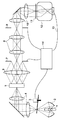
光源1として、図1では超高圧水銀ランプの例を示したが、エキシマレーザーを用いても良い。集光ミラー2は、通常楕円ミラーが用いられる。楕円ミラーの他にも、集光点の集光度を高めるよう最適化したファセットミラーなどを用いてもよい。シャッター3は、開閉時間を調整することにより、後述する感光性材料(感光剤)が塗布された基板(ウェーハ)13への露光量を調整する。露光装置においては、転写するパターンに応じて投影光学系の結像性能を最適化するために、コヒーレンスファクター(σ値)を変える必要がある。σ値は、[(照明光学系のNA)÷(投影光学系のNA)]であって、照明光学系のNAを決めているハエノ目レンズ5上の光束径を変える事によって、σ値を変えることができる。
Although an example of an ultrahigh pressure mercury lamp is shown as the light source 1 in FIG. 1, an excimer laser may be used. The
変倍リレー光学系4は、ズーム機構をもち、ハエノ目レンズ5上の光束径を変えることができる。ハエノ目レンズ5の代わりにシリンドリカルレンズアレイを用いても構わない。ハエノ目レンズ5は入射面の光束に対して波面分割を行い、射出面に2次光源を作り出す。コンデンサー光学系6は、ハエノ目レンズ5で波面分割された光束を被照明面で重畳的に重ね合わせる。これにより、被照明面で均一な照度分布を達成することができる。
The variable magnification relay
マスキングブレード7は、コンデンサー光学系6の被照明面に配置されている。マスキングブレード7は開口が可変な絞りであり、露光装置がステップアンドリピートで繰り返し転写する1つのショット領域の形状(ショット形状)を決定する。すなわち、マスキングブレード7は、ショット領域の外縁を規定する直線状の辺より外側の領域に対して光が入射しないように光を遮断する第2遮光板を構成している。リレー光学系8は、マスキングブレード7の位置に形成された照明分布を遮光板9上に投影する。リレー光学系10は、遮光板9の位置に形成された照度分布を原版(レチクル)11上に投影する。以上説明した光源1からリレー光学系10までの部材は、原版(レチクル)11を照明(光で照射)する照明系(照射系)を構成している。回転機構は、原版を照明するための照明系の光軸に平行な軸に関して遮光板9を回転させ、並進機構は、光軸に垂直な面に沿って遮光板9を並進させる。
The
遮光板9(遮蔽板または遮蔽部材ともいう)は、露光装置がステップアンドリピートで繰り返し露光する際に、ウェーハ13への露光位置に応じてパターンが転写される領域の形状を変化させることが可能である。遮光板9は、パターンが転写される基板の転写領域を規定する基板の外周から所定の幅だけ内側の円形境界線に重なる円弧を縁に含み、基板上の円形境界線より外側の外周領域に対して光が入射しないように光を遮断する遮光板を構成している。本実施形態では、配置上の都合から、リレー光学系8を用いてマスキングブレード7と遮光板9とを照射系内の互いに別の光学的に共役な位置に配置する構成を示した。
The light shielding plate 9 (also referred to as a shielding plate or a shielding member) can change the shape of a region to which a pattern is transferred according to the exposure position on the
しかし、配置上の問題がなければ、マスキングブレード7を遮光板9に隣接して配置しても良い。マスキングブレード7を遮光板9に隣接して配置する場合に、それらが実質的に同じ位置に配置できない場合には、遮光板9をウェーハ13と光学的に共役な位置に配置し、マスキングブレード7をデフォーカスさせた位置に配置する。配置上のデフォーカス量が許容できない場合には、マスキングブレード7で、ショット領域における第1方向(走査露光装置の場合、走査方向に直交する方向)に沿った外縁を規定する直線状の辺より外側の領域に対して光が入射しないように、光を遮断する。そして、ショット領域における第1方向と直交する第2方向に沿った外縁を規定する直線状の辺より外側の領域に対して光が入射しないように、レチクル(原版)11上にCrパターンで光を遮断する遮光部を設ける。さらには、ショット領域の形状はレチクル11上のCrパターンで決定し、マスキングブレード7はレチクル11上のCr欠陥による露光を低減するために、ショット領域の形状より大きな開口領域をもって遮光してもよい。マスキングブレード7および遮光板9の照射系内における配置の順番は不問で、どちらが光源1側にあっても構わない。
However, if there is no problem in arrangement, the
リレー光学系10は、遮光板9の位置に形成された照度分布をレチクル11上に投影する。レチクル(マスクとよぶ場合もある)11には、転写する回路パターンが形成されている。投影光学系12は、レチクル11上に形成されたパターンを、感光剤(レジストとよぶ場合もある)が塗布されたウェーハ(基板とよぶ場合もある)13に投影する。制御部(コンピュータ)14は、露光装置を制御し、ウェーハ13の露光を行う。
The relay
遮光板9について、以下、詳細に説明する。図2は遮光板9の実施例である。図2は図1において紙面内横(左右)方向から遮光板9を見た図である。図2に「A」で示した点線で囲まれた領域は、遮光板9上でのショット領域の形状を示しており、右上の領域が欠けたショット領域の場合、当該欠けた領域を遮光板9で遮光(遮蔽)することができる。遮光板9は、図2のように、開口を有し、開口の縁は互いに反対側の位置に配置された(互いに対向する)第1円弧(第1縁)と第2円弧(第2縁)とを含む。第1円弧及び第2円弧は、開口の内側から外側に向かう方向に凸状をなしている。円弧の半径は、投影光学系12によってウェーハ13上に投影した場合に、ウェーハ13の半径から外周領域の遮光幅dを引いたものと等しいことが望ましい。また円弧が望ましいが、ウェーハ13の周辺の遮光領域が多角形でも許容される場合には、直線であってもよい。遮光板9は基板の周辺ショット領域に応じて、第1円弧の縁および第2円弧の縁のいずれか一方により遮光して、パターンが転写(形成)される領域(露光領域)を規定する。
The
駆動部96は、照射系の光軸に平行な軸の回りの回転範囲内で遮光板9を回転駆動する第1駆動部である。駆動部95は、照射系の光軸に垂直な平面内で動径方向に遮光板9を直線駆動(並進移動)する第2駆動部である。図2の例では、駆動部95も駆動部96によって回転駆動される。当該回転の軸と光軸とは一致しているのが好ましい。なお、遮光板9を光軸に関して動径方向と回転方向とに駆動できるようになっていれば他の形態であっても構わない。駆動部96は360度未満の回転範囲をもち、この回転範囲を2つの円弧で分担して、例えば、ウェーハ13の第1、第2象限の外周領域を1つの円弧で、第3、第4象限の外周領域を他方の円弧で遮光する。
The
ウェーハの第1象限と第2象限を担当する遮光板の縁と、第3象限と第4象限を担当する遮光板の縁がある場合の露光順序と遮光板9の回転駆動の具体例を以下に示す。図3は、従来の露光順序として、ウェーハ上のショットの露光順序を例示的に表す図である。図3の矢印は、ウェーハを保持しているステージのステップ距離が最短となる露光順序を示す。この露光順序で露光を行っていくと、点線で囲んだショット領域の移動においては、第1象限を担当した遮光板の縁から、第4象限を担当する遮光板の縁へと切り替えるために、180度の回転駆動が必要となる。露光装置の生産性の向上を図るためには、ウェーハを保持しているステージのステップ時間より、この180度の回転駆動時間を短くすることが効果的である。
Specific examples of the exposure sequence and rotation driving of the
例えば、ウェーハ13を保持するステージのステップにかかる時間T1を0.1秒、遮光板の直線駆動にかかる時間T2を1秒、遮光板の20度以下の回転駆動にかかる時間T3を1秒,180度回転駆動する時間T4を5秒とする。遮光板の駆動を含まないショット間では、T1に0.1秒、遮光板が180度回転駆動するショット間では、T4に5秒、遮光板の180度以外の駆動を含むショット間では、T2=T3の1秒の時間がかかることになる。
For example, the time T1 required for the stage holding the
ウェーハ13を保持しているステージのステップ距離が最短となる、図3の矢印で示したような従来の露光順序で露光を行っていくと、遮光板の駆動を含まないショット間の移動が19回となる。また、遮光板の180度回転駆動するショットが1回、180度以外の駆動を含むショットが32回となり、ショットを移動するための時間がウェーハ1枚あたり、38.9秒かかってしまう。なお、第1象限で周辺部を遮光しながら露光を行った後、中心部の複数ショット露光を行う。その後第2象限で周辺部を遮光しながら露光する場合には、中心部の複数ショットを露光している間に、遮光板9の回転駆動を並列で実施しているため、大きな角度の回転駆動による生産性の低下は抑制される。
When exposure is performed in the conventional exposure sequence as indicated by the arrow in FIG. 3 where the step distance of the stage holding the
図4に本発明の実施形態によるウェーハ上の露光順序を表す。この露光順序におけるポイントは、以下の2点である。 FIG. 4 shows an exposure sequence on a wafer according to an embodiment of the present invention. The points in this exposure order are the following two points.
(1)遮光板を用いた遮光を必要とするショットと、遮光板を用いた遮光を必要としないショットをグループ分けすることで、遮光板を用いた遮光を必要とするショットと必要としないショットの間に発生する遮光板の駆動回数を減らしたこと。 (1) Shots that require light shielding using a light shielding plate and shots that require light shielding using a light shielding plate are grouped into shots that do not require light shielding using a light shielding plate, and shots that do not require light shielding using a light shielding plate. Reduced the number of times the shading plate is driven during
(2)遮光板の180度駆動を行う代わりに、ウェーハを第1象限から第3象限の順序に露光するようにして、遮光板の180度の回転駆動の代わりにウェーハを横切ることで遮光板の遮光する円弧の切り替えを行うようにしたこと。 (2) Instead of driving the light shielding plate by 180 degrees, the wafer is exposed in the order of the first quadrant to the third quadrant, and the light shielding plate is traversed by crossing the wafer instead of rotating the light shielding plate by 180 degrees. The arc to be shielded was changed.
コンピュータ14は、遮光板の第1円弧の縁を用いて遮光しながら回転駆動の回転範囲の一端の位置に対応する周辺ショット領域から転写を開始し、回転範囲の他端の位置に対応する周辺ショット領域まで連続して転写を行うように遮光板の回転駆動を制御する。その後、コンピュータ14(制御部)は、直線駆動によりウェーハ13を横切って周辺ショット領域を変更して、遮光板9の第2円弧の縁を用いて遮光しながら、次の周辺ショット領域の転写を行うように遮光板の回転駆動および直線駆動を制御する。
The
コンピュータ14(制御部)は入力された基板に関するレシピの情報(ショットレイアウト等のパターン形成条件の情報を含む)により、ショット領域を遮光板によって遮光しながら転写を行う周辺ショット領域と、遮光板で遮光しないショット領域とに分ける。そして、コンピュータ14(制御部)は、周辺ショット領域に対して、遮光板の回転駆動および直線駆動の制御を行う。当該制御において、第1円弧の縁を用いて遮光する最後の周辺ショット領域と、第2円弧の縁を用いて遮光する最初の周辺ショット領域との間における遮光板の回転量は90度以下となるようにする。すなわち、第1縁を含む遮蔽領域を用いた第1のパターン形成と、第2縁を含む遮蔽領域を用いた第2のパターン形成と、の間における遮光板9(遮蔽部材)の回転量は90度以下である。 The computer 14 (control unit) includes a peripheral shot region that performs transfer while shielding the shot region with the light shielding plate, and a light shielding plate based on the input recipe information about the substrate (including pattern formation condition information such as shot layout). Divide into shot areas that are not shaded. Then, the computer 14 (control unit) controls rotation driving and linear driving of the light shielding plate with respect to the peripheral shot area. In this control, the rotation amount of the light shielding plate between the last peripheral shot area shielded using the edge of the first arc and the first peripheral shot area shielded using the edge of the second arc is 90 degrees or less. To be. That is, the amount of rotation of the light shielding plate 9 (shielding member) between the first pattern formation using the shielding region including the first edge and the second pattern formation using the shielding region including the second edge is It is 90 degrees or less.
この露光順序により、遮光板9の駆動を含まないショット間の移動が24回、遮光板9の180度回転駆動するショットが0回、180度以外の駆動を含むショットが28回となり、ショットを移動するための時間がウェーハ1枚あたり、30.4秒となる。つまり、図3に示した従来の露光順序に比べて、ウェーハ1枚あたり8.5秒の短縮となり、生産性の向上が達成される。
With this exposure order, the movement between shots not including the drive of the
実施形態における露光方法を図5のフローチャートに従って説明する。まず、ステップ1001において、コヒーレンスファクター(σ値)、ショット形状、ショットレイアウト、周辺遮光幅等(レシピ情報)が、入力部によって、露光装置を制御するコンピュータ14(制御部)に入力される。コンピュータ14(制御部)は、基板に関するレシピの情報に基づいて、基板上の周辺ショット領域を特定する。また、コンピュータ14(制御部)は、基板上のショット領域に対するパターン形成の順序を決定し、決定した順序に従って駆動機構を制御する。
The exposure method in the embodiment will be described with reference to the flowchart of FIG. First, in
ステップ1002にてコンピュータ14は、入力されたレシピ(σ値)の情報に基づき変倍リレー光学系4を所定位置に駆動し、入力されたレシピ(ショット領域)の情報に基づきマスキングブレード7を駆動する。また、コンピュータ14は、入力されたレシピ情報に応じて、生産性が最大となるようなパターン形成手順(例えば図4;遮光板の駆動手順を含む)を決定する。ショットレイアウト等のレシピ情報と、ステージの駆動条件(ステップ時間等)と、遮光板の駆動条件とに応じたパターン形成手順を示す複数の手順情報が予め決められていてもよい。例えば、コンピュータ14(制御部)は、この手順情報を内部の記憶部に記憶しておき、入力されたレシピ情報に応じた手順情報を、複数の手順情報の中から選択(決定)する。コンピュータ14(制御部)は、選択した手順情報に基づいて、ステージの駆動、ならびに遮光板の並進駆動および回転駆動を制御する。尚、手順情報は、外部の装置(例えば、情報処理装置や記憶装置)に記憶しておき、コンピュータ14は、外部の装置との通信により、入力されたレシピ情報に応じた手順情報を取得して、遮光板の駆動を制御することも可能である。また、コンピュータ14(制御部)は、その他の制御を行ってもよい。
In
ステップ1003にて未露光のウェーハ13を搬入する。ステップ1004にて、コンピュータ14は、決定した手順情報に基づいて、遮光板9の駆動状態を決定する。ステップ1005にて、コンピュータ14はウェーハ13を保持しているステージを駆動して対象ショット領域を投影光学系12の下に移動させ、遮光板9を予め決定された状態に駆動する。ステップ1006にて、コンピュータ14は、シャッター3の駆動を制御することで、ウェーハ13を所定の露光量で露光する。これにより、周辺の遮光部は露光されることなく、ウェーハ13上の感光剤にレチクル11のパターンが転写される。ステップ1007にてコンピュータ14は、ウェーハ13上の全ショット領域が露光されたか判定する。露光が完了していないショット領域が残っている場合には、ステップ1004に戻って次のショット領域の露光に進む。全てのショット領域の露光が完了している場合には、そのウェーハ13の露光処理は終了となり、ステップ1008でウェーハ13は搬出される。ステップ1009でコンピュータ14は、全てのウェーハ13の露光が完了したかを判定する。未露光のウェーハ13が残っている場合には、次のウェーハ13の露光処理に進む。すべてのウェーハ13の露光が完了していれば、露光処理は終了となる。
In
以上のように本実施形態によれば、遮光板を回転する駆動機構が高速な駆動機構でなくとも、ウェーハ周辺部を遮光してパターン形成を行う、生産性(スループット)の点で有利なリソグラフィ装置または方法を提供することができる。 As described above, according to this embodiment, even if the driving mechanism for rotating the light shielding plate is not a high-speed driving mechanism, the lithography is advantageous in terms of productivity (throughput) in which the pattern is formed by shielding the wafer peripheral portion. An apparatus or method can be provided.
上記の実施形態では、リソグラフィ装置として、原版のパターンを投影光学系により基板のショット領域に投影する露光装置を例示した。しかし、リソグラフィ装置は、それに限らず、例えば、電子線等の荷電粒子線で基板にパターン形成を行うものであってもよいし、型により成形された光硬化樹脂(レジスト)への光の照射(照明)を伴うインプリント処理を行うインプリント装置であってもよい。 In the embodiment described above, the exposure apparatus that projects the pattern of the original onto the shot area of the substrate by the projection optical system is exemplified as the lithography apparatus. However, the lithographic apparatus is not limited thereto, and for example, a pattern may be formed on a substrate with a charged particle beam such as an electron beam, or light may be irradiated onto a photocurable resin (resist) molded by a mold. An imprint apparatus that performs imprint processing with (illumination) may be used.
(物品の製造方法)
物品(半導体集積回路素子、液晶表示素子、記録媒体、光学素子等)の製造方法は、上述したリソグラフィ装置を用いて基板(ウエハ、ガラスプレート、フィルム状基板)にパターンを転写(形成)する工程を含む。さらに、当該製造方法は、パターンを転写された基板に対して現像およびエッチングの少なくとも一方を行う工程を含みうる。当該製造方法は、パターンを転写された基板を加工する他の処理を含みうる。以上、実施形態について説明したが、本発明は上記の実施形態に限定されず、その要旨の範囲内で種々の変形および変更が可能である。
(Product manufacturing method)
A method of manufacturing an article (semiconductor integrated circuit element, liquid crystal display element, recording medium, optical element, etc.) is a step of transferring (forming) a pattern onto a substrate (wafer, glass plate, film-like substrate) using the above-described lithography apparatus. including. Further, the manufacturing method may include a step of performing at least one of development and etching on the substrate to which the pattern is transferred. The manufacturing method may include other processes for processing the substrate to which the pattern is transferred. As mentioned above, although embodiment was described, this invention is not limited to said embodiment, A various deformation | transformation and change are possible within the range of the summary.
Claims (15)
前記リソグラフィ装置は、
開口を規定する第1縁および第2縁を有する遮蔽部材を含み、前記第1縁および前記第2縁の一方を含む前記遮蔽部材の遮蔽領域により、パターンの転写のための光が照射されないように、前記基板の周辺領域を遮蔽する遮蔽部と、
前記遮蔽部材を回転させる回転機構と、前記遮蔽部材を並進させる並進機構とを含み、パターンを転写すべき対象の周辺ショット領域に応じて前記遮蔽部材による前記基板の遮蔽領域を変更するための駆動機構と、
前記第1グループの周辺ショット領域に対してパターンが転写されるときに前記第1縁を含む前記遮蔽領域を用いて前記周辺領域が遮蔽され、前記第2グループの周辺ショット領域に対してパターンが転写されるときに前記第2縁を含む前記遮蔽領域を用いて前記周辺領域が遮蔽される場合に、パターンを転写すべき前記第1グループの周辺ショット領域の各々について前記第1縁を含む前記遮蔽領域を用いて前記周辺領域を遮蔽しながら、前記第1グループの周辺ショット領域に対して、前記第1周辺ショット領域から前記第2周辺ショット領域まで順にパターンが転写され、その後、パターンを転写すべき前記第2グループの周辺ショット領域の各々について前記第2縁を含む前記遮蔽領域を用いて前記周辺領域を遮蔽しながら、前記第2グループの周辺ショット領域に対して、前記第3周辺ショット領域から前記第4周辺ショット領域まで順にパターンが転写されるように前記基板の前記複数のショット領域に対するパターンの転写の順序を決定し、決定した順序に従って前記駆動機構を制御する制御部と、
を有することを特徴とするリソグラフィ装置。 A lithographic apparatus for transferring a pattern to a photosensitive material on each of a plurality of shot areas of a substrate, wherein the plurality of shot areas include a first group of peripheral shot areas and a second group of peripheral shot areas, The peripheral shot area of the first group includes a first peripheral shot area and a second peripheral shot area, and the peripheral shot area of the second group is a third peripheral shot arranged next to the first peripheral shot area. An area and a fourth peripheral shot area,
The lithographic apparatus comprises:
A shielding member having a first edge and a second edge defining an opening, and the shielding region of the shielding member including one of the first edge and the second edge is prevented from being irradiated with light for pattern transfer. And a shielding part that shields a peripheral region of the substrate;
A driving mechanism for changing a shielding area of the substrate by the shielding member according to a peripheral shot area to which a pattern is to be transferred, including a rotation mechanism that rotates the shielding member and a translation mechanism that translates the shielding member; Mechanism,
When the pattern is transferred to the peripheral shot region of the first group, the peripheral region is shielded using the shield region including the first edge, and the pattern is applied to the peripheral shot region of the second group. Including the first edge for each of the first group of peripheral shot areas to which a pattern is to be transferred when the peripheral area is shielded using the shielding area including the second edge when transferred. A pattern is transferred in order from the first peripheral shot area to the second peripheral shot area to the peripheral shot area of the first group while shielding the peripheral area using a shielding area , and then the pattern is transferred. For each of the second group of peripheral shot regions to be shielded using the shielding region including the second edge, The peripheral shot area of the group, to determine the order of transfer of the pattern for the plurality of shot regions of the substrate such that the pattern is sequentially transferred from the third peripheral shot region to the fourth peripheral shot region, determined A control unit for controlling the drive mechanism according to the sequence performed ;
A lithographic apparatus comprising:
前記リソグラフィ装置は、The lithographic apparatus comprises:
開口を規定する第1縁および第2縁を有する遮蔽部材を含み、前記第1縁および前記第2縁の一方を含む前記遮蔽部材の遮蔽領域により、パターンの転写のための光が照射されないように、前記基板の周辺領域を遮蔽する遮蔽部と、A shielding member having a first edge and a second edge defining an opening, and the shielding region of the shielding member including one of the first edge and the second edge is prevented from being irradiated with light for pattern transfer. And a shielding part that shields a peripheral region of the substrate;
前記遮蔽部材を回転させる回転機構と、前記遮蔽部材を並進させる並進機構とを含み、パターンを転写すべき対象の周辺ショット領域に応じて前記遮蔽部材による前記基板の遮蔽領域を変更するための駆動機構と、A driving mechanism for changing a shielding area of the substrate by the shielding member according to a peripheral shot area to which a pattern is to be transferred, including a rotation mechanism that rotates the shielding member and a translation mechanism that translates the shielding member; Mechanism,
前記第1周辺ショット領域に対してパターンが転写されるときに前記第1縁を含む前記遮蔽領域を用いて前記周辺領域が遮蔽され、前記第2周辺ショット領域に対してパターンが転写されるときに前記第1縁を含む前記遮蔽領域を用いて前記周辺領域が遮蔽される場合に、前記第1周辺ショット領域の次に前記第2周辺ショット領域にパターンが転写され、前記第1周辺ショット領域に対してパターンが転写されるときに前記第1縁を含む前記遮蔽領域を用いて前記周辺領域が遮蔽され、前記第2周辺ショット領域に対してパターンが転写されるときに前記第2縁を含む前記遮蔽領域を用いて前記周辺領域が遮蔽される場合に、前記第1周辺ショット領域の次に前記第3周辺ショット領域にパターンが転写されるように前記基板の前記複数のショット領域に対するパターンの転写の順序を決定し、決定した順序に従って前記駆動機構を制御する制御部と、When the pattern is transferred to the first peripheral shot area, the peripheral area is shielded using the shielding area including the first edge, and the pattern is transferred to the second peripheral shot area. When the peripheral region is shielded using the shielding region including the first edge, a pattern is transferred to the second peripheral shot region next to the first peripheral shot region, and the first peripheral shot region The peripheral area is shielded using the shielding area including the first edge when a pattern is transferred to the second edge, and the second edge is used when the pattern is transferred to the second peripheral shot area. When the peripheral region is shielded using the shielding region including, the plurality of the substrates are arranged such that a pattern is transferred to the third peripheral shot region next to the first peripheral shot region. A control unit for controlling the drive mechanism according to determine the order of transfer of the pattern with respect to-shot regions were determined order,
を有することを特徴とするリソグラフィ装置。A lithographic apparatus comprising:
前記制御部は、前記レシピの情報に基づいて、前記記憶部に記憶された前記複数の情報のうちの1つを決定することを特徴とする請求項7に記載のリソグラフィ装置。 Each of the information further includes a storage unit that stores a plurality of information indicating the order of transfer of the pattern for the plurality of shot areas,
The lithographic apparatus according to claim 7 , wherein the control unit determines one of the plurality of pieces of information stored in the storage unit based on information on the recipe.
前記回転機構は、前記照明系の光軸に平行な軸に関して前記遮蔽部材を回転させ、
前記並進機構は、前記光軸に垂直な面に沿って前記遮蔽部材を並進させることを特徴とする請求項1乃至8のいずれか1項に記載のリソグラフィ装置。 It has an illumination system for illuminating the original plate,
The rotating mechanism rotates the shielding member with respect to an axis parallel to the optical axis of the illumination system,
The translation mechanism to a lithographic apparatus according to any one of claims 1 to 8, characterized in that translating the shield member along a plane perpendicular to the optical axis.
前記工程で前記パタ−ンを形成された基板を加工する工程と、
を含み、前記加工された基板から物品を製造することを特徴とする物品の製造方法。 A step of a pattern formed on the substrate using a lithographic apparatus according to any one of claims 1 to 14,
Processing the substrate on which the pattern is formed in the step;
And manufacturing an article from the processed substrate.
Priority Applications (2)
| Application Number | Priority Date | Filing Date | Title |
|---|---|---|---|
| JP2013168335A JP6288985B2 (en) | 2013-08-13 | 2013-08-13 | Lithographic apparatus and article manufacturing method |
| US14/452,725 US9529270B2 (en) | 2013-08-13 | 2014-08-06 | Lithography apparatus, and method of manufacturing article |
Applications Claiming Priority (1)
| Application Number | Priority Date | Filing Date | Title |
|---|---|---|---|
| JP2013168335A JP6288985B2 (en) | 2013-08-13 | 2013-08-13 | Lithographic apparatus and article manufacturing method |
Publications (3)
| Publication Number | Publication Date |
|---|---|
| JP2015037123A JP2015037123A (en) | 2015-02-23 |
| JP2015037123A5 JP2015037123A5 (en) | 2016-09-29 |
| JP6288985B2 true JP6288985B2 (en) | 2018-03-07 |
Family
ID=52467140
Family Applications (1)
| Application Number | Title | Priority Date | Filing Date |
|---|---|---|---|
| JP2013168335A Active JP6288985B2 (en) | 2013-08-13 | 2013-08-13 | Lithographic apparatus and article manufacturing method |
Country Status (2)
| Country | Link |
|---|---|
| US (1) | US9529270B2 (en) |
| JP (1) | JP6288985B2 (en) |
Families Citing this family (2)
| Publication number | Priority date | Publication date | Assignee | Title |
|---|---|---|---|---|
| JP7145620B2 (en) * | 2018-02-27 | 2022-10-03 | 株式会社オーク製作所 | projection exposure equipment |
| JP7162430B2 (en) * | 2018-02-27 | 2022-10-28 | 株式会社オーク製作所 | projection exposure equipment |
Family Cites Families (12)
| Publication number | Priority date | Publication date | Assignee | Title |
|---|---|---|---|---|
| JPS62136859A (en) | 1985-12-10 | 1987-06-19 | Nippon Denso Co Ltd | Plating apparatus for semiconductor wafer |
| JPH0950951A (en) * | 1995-08-04 | 1997-02-18 | Nikon Corp | Lithography method and lithography apparatus |
| US6680774B1 (en) | 2001-10-09 | 2004-01-20 | Ultratech Stepper, Inc. | Method and apparatus for mechanically masking a workpiece |
| TWI251116B (en) * | 2002-12-19 | 2006-03-11 | Asml Netherlands Bv | Device manufacturing method, computer-readable medium and lithographic apparatus |
| JP4481698B2 (en) * | 2004-03-29 | 2010-06-16 | キヤノン株式会社 | Processing equipment |
| US7777863B2 (en) * | 2007-05-30 | 2010-08-17 | Asml Netherlands B.V. | Lithographic apparatus with mask to prevent exposure of peripheral exposure region of substrate |
| JP2010135426A (en) * | 2008-12-02 | 2010-06-17 | Renesas Electronics Corp | Exposure method and apparatus |
| JP5127875B2 (en) * | 2010-04-28 | 2013-01-23 | キヤノン株式会社 | Lithographic apparatus and article manufacturing method |
| JP5789135B2 (en) * | 2011-06-17 | 2015-10-07 | キヤノン株式会社 | Exposure apparatus and device manufacturing method |
| JP5535164B2 (en) * | 2011-09-22 | 2014-07-02 | 株式会社東芝 | Imprint method and imprint apparatus |
| JP5868094B2 (en) * | 2011-09-26 | 2016-02-24 | キヤノン株式会社 | Exposure apparatus and device manufacturing method |
| JP6029289B2 (en) * | 2012-02-28 | 2016-11-24 | キヤノン株式会社 | Exposure apparatus and device manufacturing method using the same |
-
2013
- 2013-08-13 JP JP2013168335A patent/JP6288985B2/en active Active
-
2014
- 2014-08-06 US US14/452,725 patent/US9529270B2/en active Active
Also Published As
| Publication number | Publication date |
|---|---|
| US9529270B2 (en) | 2016-12-27 |
| JP2015037123A (en) | 2015-02-23 |
| US20150050813A1 (en) | 2015-02-19 |
Similar Documents
| Publication | Publication Date | Title |
|---|---|---|
| JP5127875B2 (en) | Lithographic apparatus and article manufacturing method | |
| US6767674B2 (en) | Method for obtaining elliptical and rounded shapes using beam shaping | |
| TWI569109B (en) | Method to mitigate defect printability and method for extreme ultraviolet lithography process | |
| JP2004063988A (en) | Illumination optical system, aligner having the system, and method of manufacturing device | |
| JPH0729808A (en) | Projection aligner | |
| KR20020022117A (en) | Exposure apparatus and exposure method | |
| KR100609109B1 (en) | Device Manufacturing Method, Mask Set for use in the Method, Data Set for Controlling a Programmable Patterning Device, Method of Generating a Mask Pattern and a Computer Program | |
| KR101486632B1 (en) | Exposure apparatus and device fabrication method | |
| TW200839460A (en) | Exposure apparatus and semiconductor device fabrication method | |
| JP2004247527A (en) | Illumination optical apparatus, aligner, and exposure method | |
| TW200809919A (en) | Exposure apparatus | |
| US20180174839A1 (en) | Lithography Patterning with Sub-Resolution Assistant Patterns and Off-Axis Illumination | |
| JP6288985B2 (en) | Lithographic apparatus and article manufacturing method | |
| JP2009130091A (en) | Illumination optical device, aligner, and device manufacturing method | |
| JP4235410B2 (en) | Exposure method | |
| JPH0766121A (en) | Projection aligner and fabrication of semiconductor element employing it | |
| JP3376043B2 (en) | Illumination device and projection exposure apparatus using the same | |
| JP2004266125A (en) | Projection aligner, projection exposure method, and device manufacturing method | |
| JPH0729807A (en) | Projection aligner | |
| JP2017032655A (en) | Exposure device, exposure method, and manufacturing method of article | |
| JP2004296965A (en) | Exposure mask, exposure method, and process for fabricating semiconductor device | |
| JP2019148693A (en) | Projection exposure apparatus | |
| JP2004266128A (en) | Charged particle beam exposure device and method of manufacturing semiconductor device | |
| JP2016176969A (en) | Exposure device and semiconductor device manufacturing method | |
| JP2005116848A (en) | Projecting aligner and method for manufacturing device |
Legal Events
| Date | Code | Title | Description |
|---|---|---|---|
| A521 | Written amendment |
Free format text: JAPANESE INTERMEDIATE CODE: A523 Effective date: 20160812 |
|
| A621 | Written request for application examination |
Free format text: JAPANESE INTERMEDIATE CODE: A621 Effective date: 20160812 |
|
| A977 | Report on retrieval |
Free format text: JAPANESE INTERMEDIATE CODE: A971007 Effective date: 20170525 |
|
| A131 | Notification of reasons for refusal |
Free format text: JAPANESE INTERMEDIATE CODE: A131 Effective date: 20170602 |
|
| A521 | Written amendment |
Free format text: JAPANESE INTERMEDIATE CODE: A523 Effective date: 20170801 |
|
| TRDD | Decision of grant or rejection written | ||
| A01 | Written decision to grant a patent or to grant a registration (utility model) |
Free format text: JAPANESE INTERMEDIATE CODE: A01 Effective date: 20180109 |
|
| A61 | First payment of annual fees (during grant procedure) |
Free format text: JAPANESE INTERMEDIATE CODE: A61 Effective date: 20180206 |
|
| R151 | Written notification of patent or utility model registration |
Ref document number: 6288985 Country of ref document: JP Free format text: JAPANESE INTERMEDIATE CODE: R151 |