JP6238632B2 - Inspection path - Google Patents
Inspection path Download PDFInfo
- Publication number
- JP6238632B2 JP6238632B2 JP2013165036A JP2013165036A JP6238632B2 JP 6238632 B2 JP6238632 B2 JP 6238632B2 JP 2013165036 A JP2013165036 A JP 2013165036A JP 2013165036 A JP2013165036 A JP 2013165036A JP 6238632 B2 JP6238632 B2 JP 6238632B2
- Authority
- JP
- Japan
- Prior art keywords
- floor slab
- inspection path
- lower chord
- plate
- resin
- Prior art date
- Legal status (The legal status is an assumption and is not a legal conclusion. Google has not performed a legal analysis and makes no representation as to the accuracy of the status listed.)
- Active
Links
Images


Description
本発明は、高速道路や鉄道等の橋梁の保守点検に用いられる樹脂製の検査路に関する。 The present invention relates to a resin inspection road used for maintenance inspection of bridges such as highways and railways.
橋梁に懸下させた検査路を利用して橋梁の保守点検を行っている。
検査路は足場板として機能する剛性の大きなデッキプレートと、デッキプレートの両側に起立して設けた複数の支柱と、隣り合う支柱間に横架した高欄とを具備している。
従来の検査路は金属製であったが、重量が重たく運搬や設置に労力を要することや腐食の問題を有していることから、検査路を鋼材に代わって繊維強化樹脂等の樹脂で形成することが提案されている(特許文献1)。
Maintenance inspection of the bridge is carried out using the inspection road suspended from the bridge.
The inspection path includes a rigid deck plate that functions as a scaffolding plate, a plurality of columns provided upright on both sides of the deck plate, and a balustrade horizontally placed between adjacent columns.
The conventional inspection path is made of metal, but it is heavy and requires labor and installation and has problems of corrosion. Therefore, the inspection path is made of resin such as fiber reinforced resin instead of steel. It has been proposed (Patent Document 1).
検査路には検査路の自重に加えて作業員や補修器材の載荷重が負荷する。
したがって、従来の検査路は上記載荷重のすべてをデッキプレートに作用させ、デッキプレートの強度と剛性で以て抵抗し得るように設計している。
具体的には、デッキプレートは、断面H形又はI形を呈する複数の主縦桁と、主縦桁の上面を被覆する薄い床板とで構成し、骨格を成す主縦桁の強度を上記載荷重より大きくしている。
In addition to the weight of the inspection path, the loading load of workers and repair equipment is applied to the inspection path.
Therefore, the conventional inspection path is designed so that all the loads described above are applied to the deck plate and can be resisted by the strength and rigidity of the deck plate.
Specifically, the deck plate is composed of a plurality of main stringers having a H-shaped or I-shaped cross section and a thin floor plate covering the upper surface of the main stringer, and the strength of the main stringers constituting the skeleton is described above. It is larger than the load.
従来の検査路にあっては次のような問題点がある。
<1>検査路はクレーンを使って高速道路や鉄道等の橋梁の下方に架設している。
検査路の重量は使用するクレーンの大きさだけでなく、架設費用にも大きな影響を及ぼすことから、検査路の更なる軽量化を図って架設費用を大幅削減することが望まれている。
<2>樹脂製の検査路は、単に素材を金属から樹脂に代えただけで金属製の検査路と比べて構成要素や、載荷重をデッキプレートの主縦桁の強度で支えるといった荷重負担の考え方は変わっていない。
そのため、樹脂製の検査路は金属製と比べてある程度の軽量化が図れるものの、重量、資材コスト、および架設コストの面でさらに削減し得る余地がある。
<3>従来の検査路はデッキプレートの主縦桁を構造部材として捉え、床板、支柱、および高欄は非構造部材として捉えていた。
したがって、検査路を樹脂で製作したとしても、デッキプレートの主縦桁の断面積を大きく形成しなければならず、金属材料よりも比強度が大きく、軽量化が可能であるという樹脂の特性が十分に生かされていない。
<4>繊維強化樹脂の場合、金属と比べて弾性係数が低いために、撓み制限(支間長(スパン)に対する許容撓み)によって断面が決定される。
したがって、剛性を合理的に確保するためには効率的な構造断面とする必要がある。
The conventional inspection path has the following problems.
<1> The inspection road is installed under the bridges of expressways and railways using cranes.
Since the weight of the inspection road has a great influence not only on the size of the crane used but also on the construction cost, it is desired to further reduce the construction cost by further reducing the weight of the inspection road.
<2> The inspection path made of resin simply changes the material from metal to resin, compared to the inspection path made of metal, and the load burden such as supporting the loaded load with the strength of the main stringer of the deck plate. The way of thinking has not changed.
Therefore, although the resin inspection path can be reduced to some extent as compared with metal, there is room for further reduction in terms of weight, material cost, and installation cost.
<3> In the conventional inspection path, the main string of the deck plate is regarded as a structural member, and the floor plate, the support column, and the handrail are regarded as non-structural members.
Therefore, even if the inspection path is made of resin, the cross-sectional area of the main stringer of the deck plate must be made larger, and the specific properties of the resin are that it has a higher specific strength than metal materials and can be reduced in weight. It is not fully utilized.
In the case of <4> fiber reinforced resin, since the elastic coefficient is lower than that of metal, the cross section is determined by the bending limit (allowable bending with respect to the span length (span)).
Therefore, in order to ensure rigidity reasonably, it is necessary to have an efficient structural cross section.
本発明は以上の点に鑑みて成されたもので、その目的とするところはつぎの何れかひとつの検査路を提供することにある。
<1>重量、資材コスト、および架設コストの面でさらなる削減が可能であること。
<2>樹脂の特性を十分に生かして、合理的に検査路を製作できること。
The present invention has been made in view of the above points, and an object of the present invention is to provide any one of the following inspection paths.
<1> Further reduction in terms of weight, material cost, and installation cost is possible.
<2> The inspection path can be reasonably manufactured by fully utilizing the characteristics of the resin.
本発明は、樹脂製の床版と、床版の両側辺に立設した樹脂製の高欄ユニットとを具備する検査路であって、前記高欄ユニットを構造部材となるように間隔を隔てて平行に配設した上弦材および下弦材在の間を複数の斜材で連結したトラス構造とし、前記床版の表面にスキンプレートが一体に付設されていると共に、前記スキンプレートの左右両側に該床版の橋軸方向に沿って下弦材が一体に設けられ、構造部材である前記床版と構造部材である高欄ユニットとの間が、床版および高欄ユニットの兼用補強材としての機能を有し、床版側に設けられた前記下弦材を介して接合されていることを特徴とする。
本発明の検査路は、前記床版がグレーチング版の上面にスキンプレートを一体に付設したグレーチング床版である。
本発明の検査路は、前記床版がコア材の上下面にスキンプレートを一体に付設したサンドイッチ床版であり、上下のスキンプレートの間に配設された下弦材が前記コア材の橋軸方向に沿った両側面を被覆して閉鎖している。
本発明の検査路は、前記高欄ユニットが床版の四隅に立設された端末支柱と、隣り合う端末支柱の上部間に横架された左右一対の上弦材と、隣り合う端末支柱の下部間に横架された左右一対の下弦材と、前記下弦材と上弦材の間に連結された複数の斜材とを具備する。
The present invention is an inspection path comprising a resin floor slab and a resin railing unit erected on both sides of the floor slab, wherein the railing unit is parallel to each other so as to be a structural member. A truss structure in which the upper chord member and the lower chord member disposed on the floor are connected by a plurality of diagonal members, and a skin plate is integrally attached to the surface of the floor slab, and the floor is provided on both left and right sides of the skin plate. lower chord member is provided integrally along the bridge axis direction of the plate, between the railing unit is the floor plate and the structural member is a structural member has a function as a combined reinforcement of the floor plate and the railing unit It is joined through the lower chord material provided on the floor slab side .
The inspection path of the present invention is a grating floor slab in which the floor slab is integrally provided with a skin plate on the upper surface of the grating plate.
Inspection path of the present invention, the slab is Ri sandwich deck der was attached integrally skin plate to the upper and lower surfaces of the core material, bridge lower chord member disposed between the upper and lower skin plate said core member Both sides along the axial direction are covered and closed .
The inspection path according to the present invention includes a terminal column in which the rail unit is erected at the four corners of the floor slab, a pair of left and right upper chord members laid between upper portions of adjacent terminal columns, and a lower portion of adjacent terminal columns. A pair of left and right lower chord members laid horizontally, and a plurality of diagonal members connected between the lower chord member and the upper chord member.
本発明は少なくとも次の一つの効果を得ることができる。
<1>従来の検査路は床版のみを構造部材として機能させていた。
本発明では、床版だけでなく高欄ユニットも構造部材として機能させるため、検査路の構成部材の断面積を小さくできる。
検査路の構成部材を小断面化することで重量、資材コスト、および架設コストの面でさらなる削減が可能となる。
<2>樹脂製の床版と樹脂製の高欄ユニットが構造部材として機能するため、金属材料よりも比強度が大きく、軽量化が可能であるという樹脂の特性を十分に生かして、合理的に検査路を製作することができる。
<3>本発明の検査路は、トラス構造となるため、構造全体としての曲げ剛性が高く、撓みや振動などの使用性に関して優位であり、維持管理業務に対して安全な作業環境を提供することができる。
The present invention can obtain at least one of the following effects.
<1> In the conventional inspection path, only the floor slab functions as a structural member.
In the present invention, since not only the floor slab but also the handrail unit functions as a structural member, the cross-sectional area of the constituent members of the inspection path can be reduced.
Further reduction in weight, material cost, and erection cost can be achieved by reducing the cross-section of the constituent members of the inspection path.
<2> Since the resin floor slab and the resin balustrade unit function as a structural member, the resin has a higher specific strength than metal materials and can be reduced in weight. Inspection path can be manufactured.
<3> Since the inspection road of the present invention has a truss structure, the entire structure has high bending rigidity, is superior in terms of usability such as bending and vibration, and provides a safe working environment for maintenance work. be able to.
以下に図面を参照しながら、本発明の実施形態ついて詳細に説明する。 Hereinafter, embodiments of the present invention will be described in detail with reference to the drawings.
<1>検査路の概要
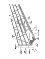
図1に示すように、本発明に係る検査路は、全長に亘って同一断面に形成した樹脂製の床版10と、床版10の長手方向Xの両側辺(左右両側)に沿って立設した樹脂製でトラス構造を呈する高欄ユニット20,20とを具備する。
<1> Outline of Inspection Path As shown in FIG. 1, an inspection path according to the present invention includes a
本発明は検査路を構成する構造部材の断面形状の縮小化、軽量化、および低コスト化を図るために、構造部材である床版10と、構造部材であるトラス形式の高欄ユニット20,20とを組み合せたものである。
従来は床版の主縦桁のみを構造部材として捉えていたが、本発明では床版10と高欄ユニット20を共に構造部材として捉えている。
殊に高欄ユニット20をトラス形式(トラス構造)とすることで構造部材と機能させるものである。
In the present invention, in order to reduce the cross-sectional shape of the structural member constituting the inspection path, reduce the weight, and reduce the cost, the floor slab 10 as the structural member and the truss-
Conventionally, only the main stringer of the floor slab is regarded as a structural member, but in the present invention, both the
In particular, the
<2>樹脂
検査路を構成する床版10と高欄ユニット20は共に樹脂素材で形成する。
樹脂素材としては、例えばガラス繊維、炭素繊維、ボロン繊維、アラミド繊維等を混入した繊維強化樹脂(FRP)を使用できる。
そのなかでもガラス繊維強化樹脂(GFRP)が好適である。
検査路の素材としては、金属材料と同等以上の強度を有しつつ、金属材料より軽量であれば公知の強化樹脂が使用可能である。
<2> Resin The
As the resin material, for example, fiber reinforced resin (FRP) mixed with glass fiber, carbon fiber, boron fiber, aramid fiber or the like can be used.
Among these, glass fiber reinforced resin (GFRP) is preferable.
As the material of the inspection path, a known reinforced resin can be used as long as it has a strength equal to or higher than that of the metal material and is lighter than the metal material.
検査路を構成するすべての部材を樹脂製とすることで、錆びの問題がなくなり、塩害の影響を受ける海岸部や、融雪剤を使用する豪雪地域での橋梁に設置した場合に有効である。 By making all the members constituting the inspection path made of resin, the problem of rust is eliminated, and it is effective when installed on a coastal area affected by salt damage or on a bridge in a heavy snow area using a snow melting agent.
<3>床版
床版10は載荷重が直接負荷する部位で、床版10に負荷した載荷重を高欄ユニット20の全体へ分散して伝達するための構造部材である。
本発明における検査路は、床版10を全長に亘って均一荷重で分散し得るように床版10全体を均質構造に形成している。
<3> Floor slab The
In the inspection path according to the present invention, the
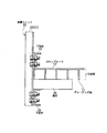
本例では床版10にグレーチング床版を適用した場合について説明する。
図2,3に示すように、本例のグレーチング床版は、縦部材と横部材を交差させて格子状に形成したグレーチング版11と、グレーチング版11の上面に取り付けた樹脂製のスキンプレート12と、スキンプレート12の両側部に形成した下弦材13とにより構成する。
In this example, a case where a grating floor slab is applied to the
As shown in FIGS. 2 and 3, the grating floor slab of this example includes a
<3.1>グレーチング版
グレーチング版11は、主部材と横部材を交差させて格子状に形成した軽量で曲げ強度の高い樹脂製の有孔パネルである。
グレーチング版11の高さや格子ピッチを変更することで、床版10の曲げ剛性を調整することができる。
<3.1> Grating Plate The
The bending rigidity of the
<3.2>スキンプレート
スキンプレート12はグレーチング版11の片面を被覆する5mmほどの薄厚の補強板であり、接着等によりグレーチング版11と一体化されている。
スキンプレート12の両側部には、その長手方向Xに沿って下弦材13が一体に形成されている。
なお、スキンプレート12と弦材13を分離独立して形成する場合もある。
<3.2> Skin Plate The
A
In some cases, the
<3.3>下弦材
下弦材13は床版10の長手方向Xに沿って連続して形成されていて、床版10および高欄ユニット20の兼用補強材として機能するだけでなく、床版10を高欄ユニット20に接続するための連結具としても機能する。
下弦材13の断面形状はC形、コ形、ボックス形、L字形等を採用できる。
<3.3> Lower chord material The
As the cross-sectional shape of the
<4>高欄ユニット
図1に示すように、高欄ユニット20は、床版10の長辺両側に立設した樹脂製でトラス構造であり、床版10の四隅に立設した端末支柱21と、床版10の長手方向に沿って配置し、隣り合う端末支柱10の上部間に横架した左右一対の上弦材22と、前記した下弦材13と上弦材22の間に連結した複数の斜材23とを具備する。
本例では支柱10間に中段水平材24を横架した形態を示すが、中段水平材24は非構造部材とする。
<4> Handrail Unit As shown in FIG. 1, the
In this example, a configuration in which the middle
<4.1>高欄ユニットの構成部材の断面形状
高欄ユニット20を構成する部材は、断面形状がC形、コ形、ボックス形、L字形等を呈する。
<4.1> Sectional Shape of Constituent Member of Handrail Unit The member constituting the
従来の樹脂製の検査路と異なるところは、本発明では床版10と高欄ユニット20を共に構造部材として機能させるため、検査路の構成部材の断面積を小さくできることである。
したがって、検査路の重量を従来と比べて大幅に軽量化できるので、検査路を橋梁等に架設する際に従来のような大型クレーンを用いる必要がなくなり、簡易な揚重機等を併用して人力で簡易に取り付けできる。
The difference from the conventional resin inspection path is that both the
Therefore, the weight of the inspection road can be significantly reduced compared to the conventional one, so there is no need to use a conventional large crane when installing the inspection road on a bridge, etc. Easy installation.
<4.2>高欄ユニットの接合手段
隣り合う端末支柱21の上部間と中段間には、高欄ユニット20の長手方向Xに沿って配置した上弦材22と中段水平材24が横架され、その各交点が固定されている。
上弦材22と下弦材13との間には、三角状に配置した複数の斜材23の両端との交点が固定してあって、全体としてトラス構造を呈している。
高欄ユニット20を構成する端末支柱21、上弦材22、斜材23、および中段水平材24の各交点の接合手段としては、公知のボルト止め、リベット止め、接着固定等を単独で、または複数の組み合せを採用できる。
<4.2> Joining means for handrail unit An
Between the
As a joining means of each intersection of the
<5>床版と高欄ユニットの連結構造
図2,3を参照して床版10と高欄ユニット20の連結構造について説明する。
高欄ユニット20を構成する隣り合う端末支柱21の最下端の間には、下弦材13と平行に下弦材25が横架してある。
本例では上下一対の下弦材13,25が協働して引張抵抗材として機能する。
さらに左右一対の下弦材25の間には、必要に応じて床版10の横断方向Yへ向けて複数の横断材26が横架してある。
横断材26の上面には床版10が搭載され、床版10の下弦材30と、高欄ユニット20を構成する端末支柱21、斜材23との交差部をボルト等で固定してある。
また、横断材26を省略し、床版10を下弦材25に直接搭載して固定してもよい。
床版10の一部に形成した下弦材13は、床版10の両側部と高欄ユニット20の下部間を連結するための兼用の連結部材として機能する。
<5> Connection Structure of Floor Slab and Handrail Unit A connection structure of the
A
In this example, the pair of upper and lower
Further, a plurality of
The
Further, the
The
床版10はその左右両側縁の上下面を下弦材13と下弦材25によって挟持される。
床版10と高欄ユニット20とを連結するにあたり重要なことは、床版10の一部に形成した下弦材13を介して荷重を伝達可能に連結してあることである。
The
What is important in connecting the
また、検査路の構成部材を樹脂製でさらに小断面に形成できることから、従来の樹脂製のものと比べて大幅な軽量化が実現できるので、橋場の悪い設置現場への搬入が容易である。 Moreover, since the constituent members of the inspection path can be made of resin and have a smaller cross section, the weight can be significantly reduced as compared with conventional resin ones, so that it is easy to carry into the installation site where the bridge is poor.
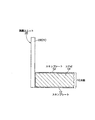
<6>検査路の荷重分散作用
図4を参照して検査路の荷重分散作用について説明する。
検査路に鉛直方向の載荷重Fが作用した場合、従来は床版の剛性のみで支持していた。
これに対して本発明では、トラス構造の高欄ユニット20も構造部材として機能するため、検査路に作用した載荷重Fは床版10だけでなく左右の高欄ユニット20,20へも分散して効率よく支持させることができる。
殊に上弦材22が圧縮抵抗材として機能し、両下弦材13,25が引張抵抗材として機能するため、撓みは小さくなる。
<6> Load Dispersion Action of Inspection Road The load distribution action of the inspection road will be described with reference to FIG.
In the case where a vertical loading load F acts on the inspection path, the load is conventionally supported only by the rigidity of the floor slab.
On the other hand, in the present invention, the truss-structured
In particular, since the
また床版10は全体を均質に形成してあるので、床版10の一部に作用した載荷重を床版10の全体に分散し、さらに下弦材13を介して床版10に作用した荷重を高欄ユニット20の全体へ分散して伝達できる。
このように検査路に作用した載荷重Fは、床版10および高欄ユニット20の剛性により協働して効率的に支持することができる。
Further, since the
Thus, the load F acting on the inspection path can be efficiently supported in cooperation with the rigidity of the
[サンドイッチ形式の床版]
図5〜7に床版10にサンドイッチ床版を適用した他の実施例を示すが、その説明に際し、前記した実施例と同一の部位は同一の符号を付してその詳しい説明を省略する。
以下に説明する複数種類のサンドイッチ床版は、従来の主縦桁および主横桁に相当する部材が存在せず、床版10の全長に亘って均質構造に形成してある。
[Sandwich floor slab]
5 to 7 show another embodiment in which a sandwich floor slab is applied to the
A plurality of types of sandwich floor slabs described below do not have members corresponding to the conventional main stringers and main cross beams, and are formed in a homogeneous structure over the entire length of the
1.開断面タイプの床版
図5に床版の側面を開放した開断面タイプの床版10を示す。
1. Open Section Type Floor Slab FIG. 5 shows an open section
<1>床版の構成
本例の床版10は樹脂製のコア材14と、コア材14の上下面を被覆するスキンプレート12,12と、各スキンプレート12の両側部にその長手方向に沿って一体に形成した下弦材13とを具備する。
スキンプレート12と下弦材13の素材や構成は先の実施例を同様である。
<1> Configuration of Floor Slab
The materials and configurations of the
<2>コア材
コア材14は硬質発泡ウレタン樹脂、硬質樹脂等からなり、一対のスキンプレート12,12の間に充填して予めスキンプレート12と一体に形成しておく。
コア材14の上下面は、一対のスキンプレート12,12で被覆するが、コア材14の側面は被覆せずに露出したままである。
コア材14の厚さを選択することで、床版10の曲げ剛性を調整することができ、支間長にも柔軟に対応できることができる。
また本例の床版10は、スキンプレート12の被覆がない場合と比べてコア材14の厚さを薄くして軽量化が可能である。
<2> Core Material The
The upper and lower surfaces of the
By selecting the thickness of the
Further, the
<3>高欄ユニットとの接合
床版10の左右両側の上下に形成した下弦材13を介して高欄ユニット20を構成する端部支柱21や斜材23と一体に接合する。
床版10の上下面に形成した連結部材を兼ねた下弦材13,13を通じて高欄ユニット20と高強度に接合できるので、下弦材13の断面寸法をさらに小さくできる。
<3> Joining to the handrail unit The end struts 21 and the
The
<4>床版の特性
本例におけるサンドイッチ形式の床版10は、曲げに抵抗する部材としても機能するが、せん断変形に抵抗する部材としても機能する。
そのため、スキンプレート12の両端部に一体化して形成した下弦材13が、引張抵抗材およびせん断抵抗材として機能する。
またコア材14に軽量な硬質発泡ウレタン樹脂を用いることで、床版10のさらなる軽量化が可能となる。
くわえて床版10の上下面を一対の下弦材13,13を介して高欄ユニット20と高強度に接合できるので、下弦材13の断面寸法を小さくして軽量化が図れることも検査路の軽量化の要因となる。
<4> Characteristics of Floor Slab Sandwich
Therefore, the
Further, by using a light rigid foamed urethane resin for the
In addition, since the upper and lower surfaces of the
2.閉断面タイプの床版
図6に床版の側面を閉鎖した閉断面タイプの床版10を示す。
2. Closed Section Type Floor Slab FIG. 6 shows a closed section
<1>床版の構成
本例の床版10は樹脂製のコア材14と、コア材14の上下面、および長辺側の側面を連続して被覆する閉断面のスキンプレート12を具備する。
スキンプレート12は閉断面に形成してあり、スキンプレート12の内部にコア材14が位置する。
スキンプレート12とコア材14の素材は既述した実施例と同様である。
<1> Configuration of Floor Slab
The
The materials of the
<2>床版と高欄ユニットの連結構造
本例の床版10と高欄ユニット20を連結するには、例えば、接着接合のほか、片側からの施工が可能なブラインドリベット、ワンサイドボルト等による連結手段を適用することができる。
その他に、床版10と高欄ユニット20の接合部に外側からガセットプレートを被せて接合する連結構造を適用することもできる。
<2> Connection structure of floor slab and handrail unit In order to connect the
In addition, it is also possible to apply a connection structure in which a gusset plate is put on and joined from the outside to the joint between the
<3>床版の特性
本例における床版10は、基本的な特性は、開断面タイプの床版と同じである。閉断面のスキンプレート12は引抜成形材であり、コストダウンが図れることから、4〜6m程度の定尺スパン等に好適である。
<3> Characteristics of floor slab The
3.複合タイプの床版
図7に図4,5のタイプを複合した床版10を示す。
3. Composite Type Floor Slab FIG. 7 shows a
<1>床版の構成
本例の床版10は樹脂製のコア材14と、コア材14の長辺側の側面と上下面を被覆する断面コ字形の下弦材13と、コア材14の上下面全面を被覆するスキンプレート12,12を具備する。
<1> Configuration of Floor Slab
<2>床版と高欄ユニットの連結構造
本例の床版10と高欄ユニット20を連結するには、例えば、接着接合のほか、片側からの施工が可能なブラインドリベット、ワンサイドボルト等による連結手段を適用することができる。
その他に、床版10と高欄ユニット20の接合部に外側からガセットプレートを被せて接合する連結構造を適用することもできる。
<2> Connection structure of floor slab and handrail unit In order to connect the
In addition, it is also possible to apply a connection structure in which a gusset plate is put on and joined from the outside to the joint between the
<3>床版の特性
本例における床版10は、基本的な特性は、開断面タイプの床版と同じである。複合タイプの床版は,全て既製の引抜成形材を用いて作製することが可能であり、引抜成形材の多様な組み合わせによって、検査路の幅、長さに対して最も柔軟に対応することができる。
<3> Characteristics of floor slab The
10・・・・床版
11・・・・グレーチング版
12・・・・スキンプレート
13・・・・下弦材
14・・・・コア材
20・・・・高欄ユニット
21・・・・端末支柱
22・・・・上弦材
23・・・・斜材
24・・・・中段水平材
25・・・・下弦材
DESCRIPTION OF
Claims (5)
前記高欄ユニットを構造部材となるように、間隔を隔てて互いに平行に配設した上弦材および下弦材在の間を複数の斜材で連結したトラス構造とし、
前記床版の表面にスキンプレートが一体に付設されていると共に、前記スキンプレートの左右両側に該床版の橋軸方向に沿って下弦材が一体に設けられ、
構造部材である前記床版と構造部材である高欄ユニットとの間が、床版および高欄ユニットの兼用補強材としての機能を有し、床版側に設けられた前記下弦材を介して接合されていることを特徴とする、
検査路。 An inspection path comprising a resin floor slab and a resin railing unit erected on both sides of the floor slab,
A truss structure in which the upper chord member and the lower chord member arranged in parallel with each other are connected with a plurality of diagonal members so that the balustrade unit becomes a structural member,
A skin plate is integrally provided on the surface of the floor slab, and a lower chord material is integrally provided on the left and right sides of the skin plate along the bridge axis direction of the floor slab,
Between the railing unit is the floor plate and the structural member is a structural member has a function as a combined reinforcement of the floor plates and railing units are bonded through the lower chord member provided on the deck side It is characterized by
Inspection road.
Priority Applications (1)
| Application Number | Priority Date | Filing Date | Title |
|---|---|---|---|
| JP2013165036A JP6238632B2 (en) | 2013-08-08 | 2013-08-08 | Inspection path |
Applications Claiming Priority (1)
| Application Number | Priority Date | Filing Date | Title |
|---|---|---|---|
| JP2013165036A JP6238632B2 (en) | 2013-08-08 | 2013-08-08 | Inspection path |
Publications (2)
| Publication Number | Publication Date |
|---|---|
| JP2015034394A JP2015034394A (en) | 2015-02-19 |
| JP6238632B2 true JP6238632B2 (en) | 2017-11-29 |
Family
ID=52543120
Family Applications (1)
| Application Number | Title | Priority Date | Filing Date |
|---|---|---|---|
| JP2013165036A Active JP6238632B2 (en) | 2013-08-08 | 2013-08-08 | Inspection path |
Country Status (1)
| Country | Link |
|---|---|
| JP (1) | JP6238632B2 (en) |
Families Citing this family (3)
| Publication number | Priority date | Publication date | Assignee | Title |
|---|---|---|---|---|
| JP6971641B2 (en) * | 2017-06-06 | 2021-11-24 | 首都高速道路株式会社 | Permanent scaffolding for bridges |
| JP7002967B2 (en) * | 2018-03-12 | 2022-01-20 | 三協立山株式会社 | Elevation passage |
| CN111622126B (en) * | 2020-06-16 | 2021-08-06 | 中铁二十五局集团第四工程有限公司 | Construction method of high-altitude vertical manned channel in high mountain rock area |
Family Cites Families (2)
| Publication number | Priority date | Publication date | Assignee | Title |
|---|---|---|---|---|
| GB2367526B (en) * | 2000-10-03 | 2004-09-15 | Intelligent Engineering | Sandwich plate panels |
| JP3128947U (en) * | 2006-11-13 | 2007-02-01 | 株式会社宮地鐵工所 | Bridge inspection road structure |
-
2013
- 2013-08-08 JP JP2013165036A patent/JP6238632B2/en active Active
Also Published As
| Publication number | Publication date |
|---|---|
| JP2015034394A (en) | 2015-02-19 |
Similar Documents
| Publication | Publication Date | Title |
|---|---|---|
| Oh et al. | Seismic performance of steel structures with slit dampers | |
| CN110747746B (en) | Temporary supporting system for small box girder type hidden cover beam prefabricated on road and bridge and construction method thereof | |
| US4615166A (en) | Structural panel | |
| JPH0733644B2 (en) | Bridge composed of deck and elements supporting the deck, particularly long-span cable-stayed bridge, and construction method thereof | |
| JP2007023714A (en) | Composite floor slab using shape steel, composite floor slab bridge or composite girder bridge and its construction method | |
| JP6238632B2 (en) | Inspection path | |
| Bank | Application of FRP Composites to Bridges in the USA | |
| KR102108335B1 (en) | Composite Steel Structure with Seismic Performance Joint | |
| CN106545115B (en) | The construction method of assembled steel concrete composite slab | |
| KR100949828B1 (en) | Steel beam and hybrid beam of steel concrete for slim floor | |
| KR100939970B1 (en) | A method of constructing a complex girder and its structure | |
| CN103556563A (en) | Steel-RPC (Reactive Powder Concrete) composite bridge | |
| CN108518008B (en) | Rigid roof structure on flexible inhaul cable structure and mounting method thereof | |
| US11332928B2 (en) | Panel of compound sheets for the construction of light-weight one-way joist slabs | |
| KR100794444B1 (en) | Construction Method of Composite Slab Bridge Using Composite Truss Girder | |
| KR20070111241A (en) | Bottom tube composite(btc) steel girder bridge system | |
| KR101912376B1 (en) | Plate truss girder and composite girder bridge using the same | |
| RU2609504C1 (en) | Steel and concrete bridge span | |
| KR101011866B1 (en) | The truss combinations in the steel pipe girder | |
| JP3931635B2 (en) | Composite box girder and its construction method | |
| JP6714115B1 (en) | Bridge inspection scaffolding | |
| CN204139414U (en) | Composite plate trussed construction unit and structure thereof | |
| JP2020143479A (en) | Unit truss | |
| JP7292724B2 (en) | Roof structure and roof construction method | |
| CN212956124U (en) | Combined multi-span bridge plate connecting structure |
Legal Events
| Date | Code | Title | Description |
|---|---|---|---|
| A621 | Written request for application examination |
Free format text: JAPANESE INTERMEDIATE CODE: A621 Effective date: 20160630 |
|
| A131 | Notification of reasons for refusal |
Free format text: JAPANESE INTERMEDIATE CODE: A131 Effective date: 20170523 |
|
| A977 | Report on retrieval |
Free format text: JAPANESE INTERMEDIATE CODE: A971007 Effective date: 20170524 |
|
| A521 | Written amendment |
Free format text: JAPANESE INTERMEDIATE CODE: A523 Effective date: 20170713 |
|
| TRDD | Decision of grant or rejection written | ||
| A01 | Written decision to grant a patent or to grant a registration (utility model) |
Free format text: JAPANESE INTERMEDIATE CODE: A01 Effective date: 20171010 |
|
| A61 | First payment of annual fees (during grant procedure) |
Free format text: JAPANESE INTERMEDIATE CODE: A61 Effective date: 20171031 |
|
| R150 | Certificate of patent or registration of utility model |
Ref document number: 6238632 Country of ref document: JP Free format text: JAPANESE INTERMEDIATE CODE: R150 |
|
| S533 | Written request for registration of change of name |
Free format text: JAPANESE INTERMEDIATE CODE: R313533 |
|
| R350 | Written notification of registration of transfer |
Free format text: JAPANESE INTERMEDIATE CODE: R350 |
|
| R250 | Receipt of annual fees |
Free format text: JAPANESE INTERMEDIATE CODE: R250 |