JP6234486B2 - Motorcycle - Google Patents
Motorcycle Download PDFInfo
- Publication number
- JP6234486B2 JP6234486B2 JP2016013722A JP2016013722A JP6234486B2 JP 6234486 B2 JP6234486 B2 JP 6234486B2 JP 2016013722 A JP2016013722 A JP 2016013722A JP 2016013722 A JP2016013722 A JP 2016013722A JP 6234486 B2 JP6234486 B2 JP 6234486B2
- Authority
- JP
- Japan
- Prior art keywords
- cable
- brake
- interlocking
- brake cable
- interlocking brake
- Prior art date
- Legal status (The legal status is an assumption and is not a legal conclusion. Google has not performed a legal analysis and makes no representation as to the accuracy of the status listed.)
- Active
Links
Images


Classifications
-
- B—PERFORMING OPERATIONS; TRANSPORTING
- B62—LAND VEHICLES FOR TRAVELLING OTHERWISE THAN ON RAILS
- B62L—BRAKES SPECIALLY ADAPTED FOR CYCLES
- B62L3/00—Brake-actuating mechanisms; Arrangements thereof
- B62L3/04—Brake-actuating mechanisms; Arrangements thereof for control by a foot lever
-
- B—PERFORMING OPERATIONS; TRANSPORTING
- B62—LAND VEHICLES FOR TRAVELLING OTHERWISE THAN ON RAILS
- B62L—BRAKES SPECIALLY ADAPTED FOR CYCLES
- B62L3/00—Brake-actuating mechanisms; Arrangements thereof
- B62L3/08—Mechanisms specially adapted for braking more than one wheel
Description
本発明は、連動ブレーキシステムを備える自動二輪車に関する。 The present invention relates to a motorcycle including an interlocking brake system.
二輪車において、1つの操作子を操作することで、前輪ブレーキ及び後輪ブレーキに制動力を与えることができる連動ブレーキシステム(CBS)が知られている。(例えば、特許文献1(図8)参照)。 In a two-wheeled vehicle, an interlocking brake system (CBS) is known in which a braking force can be applied to a front wheel brake and a rear wheel brake by operating one operator. (For example, refer to Patent Document 1 (FIG. 8)).
特許文献1の図8に示されるように、ブレーキペダル(30)(括弧付き数字は、特許文献1に記載された符号を示す。以下同様)から延びる連動ブレーキケーブル(50)は、メインフレーム(12)に沿って延ばされた後、ヘッドパイプ(11)の前方まで導かれる。 As shown in FIG. 8 of Patent Document 1, the interlocking brake cable (50) extending from the brake pedal (30) (the numbers in parentheses indicate the symbols described in Patent Document 1. The same applies hereinafter) 12) and then led to the front of the head pipe (11).
連動ブレーキケーブル(50)は、中空のアウターチューブと、このアウターチューブ内を移動するインナーケーブルとから構成される。このような構造の連動ブレーキケーブルでは、インナーチューブの作動にともなってアウターチューブとインナーケーブルとの間で摩擦抵抗(以下、フリクションと記す。)が発生する。 The interlocking brake cable (50) includes a hollow outer tube and an inner cable that moves in the outer tube. In the interlock brake cable having such a structure, frictional resistance (hereinafter referred to as friction) is generated between the outer tube and the inner cable in accordance with the operation of the inner tube.
このフリクションは連動ブレーキケーブルの曲率半径(曲げ半径)が小さいほど大きくなるため、曲率半径を過小にしないことや湾曲箇所を減らすなどの工夫が必要であった。 Since this friction increases as the curvature radius (bending radius) of the interlocking brake cable decreases, it has been necessary to devise measures such as not reducing the curvature radius and reducing the number of curved portions.
そこで、本発明は、自動二輪車において、インナーケーブルとアウターチューブの間に発生する連動ブレーキケーブルのフリクションを小さくすることができる連動ブレーキケーブルの配索構造を提供することを課題とする。 Accordingly, an object of the present invention is to provide an interlocking brake cable routing structure capable of reducing friction of the interlocking brake cable generated between the inner cable and the outer tube in a motorcycle.
請求項1に係る発明は、前輪ブレーキと、後輪ブレーキと、前記前輪ブレーキ及び前記後輪ブレーキを制動させるための力を発生させるブレーキペダルと、このブレーキペダルで発生した力を分配する連動機構と、この連動機構で分配した力を前記前輪ブレーキへ伝達する連動ブレーキケーブルと、ステアリング軸を回動可能に支持するヘッドパイプと、このヘッドパイプから車両後方へ延びるメインフレームと、前記ヘッドパイプで支持されるステアリング軸の下端に設けられるボトムブリッジとを備えている自動二輪車であって、
前記連動ブレーキケーブルは、前記メインフレームの上面部に設けられた第1ケーブル支持部と、前記ボトムブリッジに設けられた第2ケーブル支持部とで支持され、
前記第1ケーブル支持部と前記第2ケーブル支持部との間で、前記連動ブレーキケーブルは、車両側面視で車両前方へ斜め上に凸状になるように湾曲する湾曲凸部を有するように支持され、
第1ケーブル支持部は、連動ブレーキケーブルに沿って延びる軸線を有しており、この軸線は、車両平面視で、前輪ブレーキ側に傾斜して設けられていることを特徴とする。
The invention according to claim 1 is a front wheel brake, a rear wheel brake, a brake pedal that generates a force for braking the front wheel brake and the rear wheel brake, and an interlocking mechanism that distributes the force generated by the brake pedal. An interlock brake cable that transmits the force distributed by the interlock mechanism to the front wheel brake, a head pipe that rotatably supports the steering shaft, a main frame that extends rearward from the head pipe, and the head pipe. A motorcycle having a bottom bridge provided at a lower end of a supported steering shaft,
The interlocking brake cable is supported by a first cable support portion provided on an upper surface portion of the main frame and a second cable support portion provided on the bottom bridge,
Between the first cable support portion and the second cable support portion, the interlocking brake cable is supported so as to have a curved convex portion that curves so as to protrude obliquely upward toward the front of the vehicle in a side view of the vehicle. It is,
The first cable support portion has an axis extending along the interlocking brake cable, and the axis is provided to be inclined toward the front wheel brake in a plan view of the vehicle .
請求項2に係る発明では、第2ケーブル支持部はケーブルを支持する軸線が側面視で後下がりに傾斜しており、連動ブレーキケーブルの湾曲凸部の少なくとも一部は、ステアリング軸の軸線よりも前方になるように支持されていることを特徴とする。 In the invention according to claim 2 , the axis supporting the cable in the second cable support portion is inclined rearwardly downward in a side view, and at least a part of the curved convex portion of the interlocking brake cable is more than the axis of the steering shaft. It is supported so that it may become the front.
請求項1に係る発明によれば、連動ブレーキケーブルはメインフレームの上面からボトムブリッジまでの間で湾曲するように支持されているため、屈曲半径が小さくならず、ブレーキケーブルに発生するフリックションを小さくすることができる。
よって、本発明によれば、インナーケーブルとアウターチューブの間に発生する連動ブレーキケーブルのフリクションを小さくすることができる連動ブレーキケーブルの配索構造が提供される。
According to the first aspect of the invention, since the interlocking brake cable is supported so as to bend between the upper surface of the main frame and the bottom bridge, the bending radius is not reduced, and the flick generated in the brake cable is prevented. Can be small.
Therefore, according to the present invention, there is provided an interlocking brake cable routing structure capable of reducing the friction of the interlocking brake cable generated between the inner cable and the outer tube.
また、請求項1に係る発明では、連動ブレーキケーブルが、前輪ブレーキ側に傾斜して設けられるため、転蛇がより円滑になる。 Moreover, in the invention which concerns on Claim 1 , since the interlocking brake cable is inclined and provided in the front-wheel brake side, snakes become smoother.
請求項2に係る発明では、連動ブレーキケーブルの湾曲凸部の少なくとも一部が、ステアリング軸の軸線よりも前方になるように支持されているため、転蛇を湾曲凸部で吸収させ易くなる。 In the invention according to claim 2 , since at least a part of the curved convex portion of the interlocking brake cable is supported so as to be ahead of the axis of the steering shaft, the snake is easily absorbed by the curved convex portion.
本発明の実施の形態を添付図に基づいて以下に説明する。なお、図面は符号の向きに見るものとする。また、図中の「前・後、左・右、上・下」はシートに座った運転者を基準にして定めた方向を示す。 Embodiments of the present invention will be described below with reference to the accompanying drawings. The drawings are viewed in the direction of the reference numerals. In addition, “front / rear, left / right, up / down” in the figure indicates a direction determined based on the driver sitting on the seat.
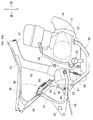
図1に示すように、自動二輪車10は、車体フレーム30と、この車体フレーム30で支えられるパワーユニット12と、スイングアーム13で回転自在に支持される後輪14と、車体フレーム30の前部のヘッドパイプ31で支持されるステアリング軸15と、このステアリング軸15の上端に取付けられるトップブリッジ16と、ステアリング軸15の下端に取付けられるボトムブリッジ17と、これらのトップブリッジ16及びボトムブリッジ17で支持され前輪18を回転自在に支えるフロントサスペンション19と、車体フレーム30上に配置される燃料タンク20及びシート21とを備えている。パワーユニット12は、ガソリンエンジンなどの内燃機関が好適であるが、電動モータであってもよい。
As shown in FIG. 1, the
車体フレーム30は、ヘッドパイプ31と、このヘッドパイプ31から車両後方へ延びるメインフレーム32と、このメインフレーム32の後部から斜め下へ延びるピボットフレーム33と、ヘッドパイプ31から斜め下へ延びるダウンフレーム34を有する。ダウンフレーム34とピボットフレーム33とでパワーユニット12を支持する。
The
ピボットフレーム33でスイングアーム13が上下動自在に支持される。メインフレーム32の後端から車両後方へ延びるシートフレーム35でシート21を支える。そして、シートフレーム35とスイングアーム13とにリヤサスペンション22が渡されている。
The
前輪18と後輪14の間(この例ではパワーユニット12の後方位置)に、運転者が足を載せるメインステップ28及び運転者が操作するキックペダル29が配置されると共に前輪ブレーキ23と後輪ブレーキ24に制動力は分配する連動機構60が設けられている。この連動機構60の詳細は図2で説明する。
Between the
トップブリッジ16にハンドルホルダ25を介してステアリングハンドル26が取付けられ、このステアリングハンドル26に取付けられる右グリップ27に第1操作子41が配置され、この第1操作子41から前輪ブレーキ23まで第1線状部材としての第1伝達部材42が延びている。
A
第1操作子41は、フロントブレーキレバーが好適であるが、ブレーキペダルであってもよく、種類形式は問わない。また、第1線状部材としての第1伝達部材42は、制動力を機械的に伝え得るブレーキケーブルが好適であるが、ブレーキロッドや制動油圧を伝えるブレーキホース(又はブレーキ配管)であってもよい。
The
また、パワーユニット12の近傍に配置されている連動機構60から前輪ブレーキ23まで、第2伝達部材としての連動ブレーキケーブル43が延びている。この連動ブレーキケーブル43は車両前後方向において、斜め上に延びた後に前方へ湾曲し、シートフレーム35及びメインフレーム32に沿って延び、ステアリング軸15の近傍で下方へ湾曲して前輪ブレーキ23に達する。
An interlocking
なお、連動機構60は、第2操作子45で駆動される。連動機構60から第3伝達部材46が後輪ブレーキ24まで延びている。第2操作子45は、ブレーキペダルが好適であるが、ブレーキレバーであってもよい。第3伝達部材46は、ブレーキロッドが好適であるが、ブレーキホースやブレーキワイヤであってもよい。
The
また、トップブリッジ16の車両前方にスピードメータ47及び前照灯48が配置され、スピードメータ47から第2線状部材としてのスピードメータケーブル49が前輪ブレーキ23の近傍まで延びている。
Further, a
図2に示すように、シートフレーム35は、ピボットフレーム33から斜め上に延びるサブフレーム36で補強されている。このサブフレーム36とピボットフレーム33にL字状のピリオンステップブラケット37が取付けられ、このピリオンステップブラケット37に、同乗者が足を載せるピリオンステップ38が取付けられている。
As shown in FIG. 2, the
第2操作子45は、ピボットフレーム33に回転軸51を介して取付けられる。第2操作子45がブレーキペダルである場合は、前端に踏み面52を備え、後端に且つ回転軸51から上に延びるアーム部53を備える。
The
連動機構60は、アーム部53の上部に連結軸61を介して回転自在に取付けられる縦長板状のイコライザ62と、このイコライザ62の上端とピリオンステップブラケット37の上端とに掛け渡したディレイスプリング63と、連結軸61よりも下方へ延びるイコライザ62の下部に設けられるストッパピン64とを有する。
The
イコライザ62の上部に連動ブレーキケーブル43が連結され、イコライザ62の下部に第3伝達部材46が連結される。
第2操作子45は、ペダルスプリング54で上方へ付勢されている。車体フレーム側に設けたストッパ部39にアーム部53の後面が当たることで、図反時計回りの回転が抑制される。
The interlocking
The
乗員が踏み面52を踏むと、第2操作子45は回転軸51を中心に図時計方向へ回転する。アーム部53は車両前方へ移動する。この移動により、第3伝達部材46が引かれる。
When the occupant steps on the
なお、第2操作子45の操作初期段階では、縦長のイコライザ62は、上部がディレイスプリング63で車両前方への移動が制限されるため、連動ブレーキケーブル43は引かれない。
イコライザ62の上部とアーム部53とは、車両前方に開くV字形を呈しているが、アーム部53が車両前方へ移動することで、I字になろうとする。ストッパピン64がイコライザ62に接触すると、この後はアーム部53に連動して、イコライザ62は車両前方へ移動し始め、連動ブレーキケーブル43が引かれ始める。
In the initial operation stage of the
The upper portion of the
第3伝達部材46よりも遅れて連動ブレーキケーブル43が引かれる。
このように第2操作子(ブレーキペダル45)で発生する力は、連動機構60で連動ブレーキケーブル43と第3伝達部材46とに分配される。
The interlocking
Thus, the force generated by the second operator (brake pedal 45) is distributed to the interlocking
なお、連動ブレーキケーブル43は、アウターチューブ43aと、このアウターチューブ43a内を移動するインナーケーブル43bとからなる。アウターチューブ43aは、インナーケーブル43bを包んで保護する役割を果たす。
The interlocking
図3に示すように、メインフレーム32に沿って車両後方からヘッドパイプ31に向かって延びる連動ブレーキケーブル43は、ステアリング軸15の近傍で下へ方向を変え、下方へ十分に延びた後に車両前方へ方向を変えて前輪ブレーキ23に連結される。
As shown in FIG. 3, the interlocking
また、図1の第1操作子41から延びる第1伝達部材42は、ステアリング軸15の近傍から連動ブレーキケーブル43に沿って下がり、前輪ブレーキ23に連結される。
また、図1のスピードメータ47から延びるスピードメータケーブル49は、ステアリング軸15の近傍から連動ブレーキケーブル43に沿って下がり、前輪18のホイールハブ55に連結される。
Further, the
A
連動ブレーキケーブル43は、メインフレーム32の上面部32Bに設けた第1ケーブル支持部70と、ボトムブリッジ17に設けた第2ケーブル支持部80とで保持される。
第1ケーブル支持部70の軸線71が側面視で車両前方へ斜め上に延びており、第2ケーブル支持部80の軸線81が側面視で後下がりに傾斜するように延びているため、第1ケーブル支持部70と第2ケーブル支持部80との間において、車両斜め前方へ凸となるように、連動ブレーキケーブル43は湾曲している。
The interlocking
Since the
すなわち、図3に示すように、第2ケーブル支持部80はケーブルを支持する軸線81が側面視で後下がりに傾斜しており、連動ブレーキケーブル43の湾曲凸部43Aの少なくとも一部は、ステアリング軸15の軸線15Aよりも前方になるように支持されている。
また、図1に示すように、車両側面視で、シリンダヘッド12Aの前端よりも前側に第1ケーブル支持部70が設けられている。
That is, as shown in FIG. 3, in the second
Moreover, as shown in FIG. 1, the 1st
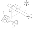
第1ケーブル支持部70と第2ケーブル支持部80の好適な構造を、次に説明する。
図4に示すように第1ケーブル支持部70は、鋼線を曲げて形成した単純な止め金具であり、車幅方向に水平に移動する連動ブレーキケーブル43を収納する第1ポケット部72と、上へ移動する連動ブレーキケーブル43を上から抑える第2ポケット部73とを有する。
好ましくは、連動ブレーキケーブル43に、一対の鍔74、74が付いた筒75を嵌めて固定する。
A preferred structure of the first
As shown in FIG. 4, the first
Preferably, a
第1ポケット部72の外幅W1は、鍔74と鍔74の内幅W2より若干(0.5mm程度)狭くする。
筒75を第1ポケット部72に嵌めると、一対の鍔74、74により、連動ブレーキケーブル43が車両前後方向へ移動することがなくなる。加えて、第2ポケット部73で上方への移動が抑制されるため、筒75は前・後、左・右、上・下へ移動することがない。
The outer width W1 of the
When the
図5(a)に示すように、第2ケーブル支持部80は、帯状の金属板82の両端にビス穴83、83を設け、中央にU字切り欠き84、84を設け、U字切り欠き84、84を除く部位に折り曲げ形成したフランジ部85、85を有し、折り曲げられたホルダ部材であって、U字切り欠き84とビス穴83、83との間に、主保持部87と第1副保持部88と第2副保持部89とが形成されている。
As shown in FIG. 5A, the second
図5(b)に示すグロメット91、92を準備する。グロメット91、92の各々は、上下に鍔93、93を有する。一方のグロメット91は、連動ブレーキケーブル43が挿通された状態で、主保持部87にセットされる。他方のグロメット92は、第1伝達部材42が挿通された状態で、第2副保持部89にセットされる。
図5(c)に示すように、連動ブレーキケーブル43と、スピードメータケーブル49と、第1伝達部材42とが、並んだ状態で第2ケーブル支持部としてのホルダ部材80で保持され、この状態のホルダ部材80がビスやボルトなどの締結部材95により、ボトムブリッジ17に固定される。
As shown in FIG.5 (c), the interlocking
連動ブレーキケーブル43のアウターチューブ43aは、グロメット91を介してホルダ部材80で挟まれる。グロメット91は鍔93がフランジ部85(断面図につき上のフランジ部は不図示)に当たるため、上下方向(図面表裏方向)に抜ける心配はない。そして、グロメット91が円形を保つため、アウターチューブ43aが偏平化する心配がない。アウターチューブ43aが円形を保つため、内部のインナーケーブル43bの移動が妨げられない。
The
第1伝達部材42は連動ブレーキケーブル43と同様であるため、説明は省略する。
一方、スピードメータケーブル49は、ホルダ部材80の内面から十分な隙間が確保されるため、上下方向(図面表裏方向)に自由に移動する。
Since the
On the other hand, the
図6に示すように、ホルダ部材80は、ボトムブリッジ17に締結部材95で固定されるが、締結部材95はステアリング軸15のごく近傍にねじ込みなどにより締結される。
そして、外径が近似する連動ブレーキケーブル43と、スピードメータケーブル49と、第1伝達部材42とは、連動ブレーキケーブル43が最もステアリング軸15に近い位置に配置される。結果、連動ブレーキケーブル43は、転蛇の影響を少なくすることができる。
As shown in FIG. 6, the
The interlocking
スピードメータケーブル49が、次にステアリング軸15に近い位置に配置される。スピードメータケーブル49も、転蛇の影響を少なくすることができる。
The
図7に示すように、車幅中心線32aの車幅方向一方(この例では左方)に前輪ブレーキ32が配置されている。そして、第1ケーブル支持部70の軸線71は、車幅中心線を兼ねるメインフレーム32の中心軸(車両長手軸)32aに対して、前輪ブレーキ32側へ角度θだけ傾斜している。このような第1ケーブル支持部70で支持される連動ブレーキケーブル43は、車両平面視で、比較的短い経路を通ってホルダ部材80に至る。
As shown in FIG. 7, the
トップブリッジ16の車両前方に配置されるスピードメータ47から延びるスピードメータケーブル49は、比較的短い経路を通ってホルダ部材80に至る。
第1操作子41から延びる第1伝達部材42は、ステアリングハンドル26に沿って延びた後、トップブリッジ16の下を通ってホルダ部材80に至る。
A
The
なお、実施例では、図5(c)に示したように、第2ケーブル支持部としてのホルダ部材80に、主保持部87と第1副保持部88と第2副保持部98を設け、主保持部87で連動ブレーキケーブル43を保持し、第1副保持部88で第2線状部材としてのスピードケーブル49を保持し、第2副保持部89で第1線状部材42を保持するようにした。
第1・第2線状部材42、49は、ケーブルと配管の何れであってもよい。
すなわち、実施例では、ホルダ部材80で、1本の連動ブレーキケーブル43と2本ケーブル(又は配管)42、49を保持するようにした。
In the embodiment, as shown in FIG. 5C, the
The first and second
That is, in the embodiment, the
しかし、2本ケーブル(又は配管)は、1本又は3本以上であってもよい。すなわち、ホルダ部材80は、ケーブル又は配管からなる少なくとも1本の線状部材42又は49と、連動ブレーキケーブル43とを一括して支持する第2ケーブル支持部材である。
However, the number of the two cables (or pipes) may be one or three or more. That is, the
また、図6にて、外径がほぼ同じ連動ブレーキケーブル43とスピードメータケーブル49と第1伝達部材42のうち、連動ブレーキケーブル43を最もステアリング軸15寄りに配置したが、連動ブレーキケーブル43より十分に小径のワイヤ又は管であれば、連動ブレーキケーブル43よりもステアリング軸15に寄った位置にてホルダ部材80で支持させることは差し支えない。
In FIG. 6, among the interlocking
図7にて、連動ブレーキケーブル43を他のケーブル又は配管42、49に比べて、ステアリング軸15寄りに配置した。ステアリング軸15から連動ブレーキケーブル43までの半径は、ステアリング軸15から他のケーブル又は配管42、49までの半径より小さくなり、旋回に係る移動距離が小さくなる。旋回に係る移動距離が小さくなれば、連動ブレーキケーブル43のフリクションを小さくすることができる。結果、他のケーブル又は配管42、49に比べて連動ブレーキケーブル43は、転蛇の影響を少なくすることができる。
In FIG. 7, the interlocking
図6に示すように、ホルダ部材80は、ボトムブリッジ17に取付けられる。
図3に示すように、ボトムブリッジ17は前輪18と共に転蛇される。前輪18はフロントサスペンション19により上下に移動可能に支持される。連動ブレーキケーブル43は、ホルダ部材80よりも上側の部位で転蛇を吸収し、ホルダ部材80よりも下側の部位でフロントサスペンション19の作動を吸収すればよく、それぞれ、転蛇とサスペンションの動きを個別に考慮することができるため、連動ブレーキケーブル43の配索を含む設計が容易になる。
As shown in FIG. 6, the
As shown in FIG. 3, the
図5(c)に示すように、スピードメータケーブル49はグロメットを介することなく第1副保持部88に挿通される。図3に示すように、スピードメータケーブル49は、前輪18のホイールハブ55と、上方のスピードメータ(図1、符号47)とを繋いでいる。このスピードメータケーブル49が、第1副保持部88に挿通されるだけであるため、ホイールハブ55とスピードメータ47の間で十分にスピードメータケーブル49を移動する長さを確保することができる。
As shown in FIG. 5C, the
また、図3で説明したように、連動ブレーキケーブル43は、第1ケーブル支持部70と第2ケーブル支持部80との間において、車両斜め前方へ凸となるように、連動ブレーキケーブル43は湾曲している。
連動ブレーキケーブル43がメインフレーム32の上面からボトムブリッジ17までの間で円弧を描くように湾曲して支持されているため、屈曲半径は十分な大きさに確保できる。曲率半径が大きいと、インナーケーブル(図4、符号43b)がアウターチューブ(図4、符号43a)に強く接触することがなくなり、結果、連動ブレーキケーブル43に発生するフリックションを小さくすることができる。
Further, as described in FIG. 3, the
Since the interlocking
さらには、図7で説明したように、連動ブレーキケーブル43が、前輪ブレーキ32側に傾斜して設けられるため、連動ブレーキケーブル43を車幅方向に蛇行させる必要が無くなり、ケーブル長さを短くすることができるため、フリックションを小さくすることができる。フリクションが小さいため、制動操作がより円滑に且つより軽く行える。
Furthermore, as explained in FIG. 7, the interlocking
本発明は、連動ブレーキシステムを備える自動二輪車に好適である。 The present invention is suitable for a motorcycle including an interlocking brake system.
10…自動二輪車、15…ステアリング軸、17…ボトムブリッジ、23…前輪ブレーキ、24…後輪ブレーキ、31…ヘッドパイプ、32…メインフレーム、43…連動ブレーキケーブル、45…ブレーキペダル、60…連動機構、70…第1ケーブル支持部、80…第2ケーブル支持部材(ホルダ部材)。
DESCRIPTION OF
Claims (2)
前記連動ブレーキケーブル(43)は、前記メインフレーム(32)の上面部(32B)に設けられた第1ケーブル支持部(70)と、前記ボトムブリッジ(17)に設けられた第2ケーブル支持部(80)とで支持され、
前記第1ケーブル支持部(70)と前記第2ケーブル支持部(80)との間で、前記連動ブレーキケーブル(43)は、車両側面視で車両前方へ斜め上に凸状になるように湾曲する湾曲凸部(43A)を有するように支持され、
前記第1ケーブル支持部(70)は、前記連動ブレーキケーブル(43)に沿って延びる軸線(71)を有しており、この軸線(71)は、車両平面視で、前記前輪ブレーキ(23)側に傾斜して設けられていることを特徴とする自動二輪車。 A front wheel brake (23), a rear wheel brake (24), a brake pedal (45) for generating a force for braking the front wheel brake (23) and the rear wheel brake (24), and the brake pedal (45 ), An interlocking mechanism (60) that distributes the force generated by the interlocking mechanism (60), an interlocking brake cable (43) that transmits the force distributed by the interlocking mechanism (60) to the front wheel brake (23), and a steering shaft (15). A head pipe (31) that is movably supported, a main frame (32) that extends rearward from the head pipe (31), and a lower end of a steering shaft (15) that is supported by the head pipe (31). A motorcycle (10) comprising a bottom bridge (17),
The interlocking brake cable (43) includes a first cable support (70) provided on the upper surface (32B) of the main frame (32) and a second cable support provided on the bottom bridge (17). (80) and
Between the first cable support part (70) and the second cable support part (80), the interlocking brake cable (43) is curved so as to protrude obliquely upward in the vehicle front view. is supported so as to have a curved convex portion (43A) which,
The first cable support portion (70) has an axis (71) extending along the interlocking brake cable (43), and the axis (71) is the front wheel brake (23) in a plan view of the vehicle. A motorcycle characterized by being inclined to the side .
前記連動ブレーキケーブル(43)の湾曲凸部(43A)の少なくとも一部は、ステアリング軸(15)の軸線(15A)よりも前方になるように支持されていることを特徴とする請求項1に記載の自動二輪車。 The second cable support portion (80) has an axis (81) for supporting the cable inclined downward in a side view,
At least a portion of the curved convex portion of the interlock brake cable (43) (43A) is in claim 1, characterized in that it is supported so as to be forward of the axis of the steering shaft (15) (15A) The described motorcycle.
Priority Applications (2)
| Application Number | Priority Date | Filing Date | Title |
|---|---|---|---|
| JP2016013722A JP6234486B2 (en) | 2016-01-27 | 2016-01-27 | Motorcycle |
| CN201710061428.0A CN107031780B (en) | 2016-01-27 | 2017-01-26 | It is two-wheeled |
Applications Claiming Priority (1)
| Application Number | Priority Date | Filing Date | Title |
|---|---|---|---|
| JP2016013722A JP6234486B2 (en) | 2016-01-27 | 2016-01-27 | Motorcycle |
Publications (2)
| Publication Number | Publication Date |
|---|---|
| JP2017132357A JP2017132357A (en) | 2017-08-03 |
| JP6234486B2 true JP6234486B2 (en) | 2017-11-22 |
Family
ID=59504003
Family Applications (1)
| Application Number | Title | Priority Date | Filing Date |
|---|---|---|---|
| JP2016013722A Active JP6234486B2 (en) | 2016-01-27 | 2016-01-27 | Motorcycle |
Country Status (2)
| Country | Link |
|---|---|
| JP (1) | JP6234486B2 (en) |
| CN (1) | CN107031780B (en) |
Families Citing this family (3)
| Publication number | Priority date | Publication date | Assignee | Title |
|---|---|---|---|---|
| CN113135258B (en) * | 2020-01-20 | 2023-03-10 | 雅马哈发动机株式会社 | Saddle-ride type vehicle |
| CN112046667A (en) * | 2020-09-17 | 2020-12-08 | 宁子怡 | Bicycle front and rear wheel cooperative brake device |
| WO2023053224A1 (en) * | 2021-09-28 | 2023-04-06 | 本田技研工業株式会社 | Saddled vehicle |
Family Cites Families (8)
| Publication number | Priority date | Publication date | Assignee | Title |
|---|---|---|---|---|
| JPS5747282A (en) * | 1980-09-04 | 1982-03-18 | Yamaha Motor Co Ltd | Front and rear interlocking brake for autobicycle |
| JPS58188287U (en) * | 1982-06-07 | 1983-12-14 | 本田技研工業株式会社 | Motorcycle interlocking brake device |
| JP5129673B2 (en) * | 2008-07-07 | 2013-01-30 | 本田技研工業株式会社 | Motorcycle |
| JP5025582B2 (en) * | 2008-07-07 | 2012-09-12 | 本田技研工業株式会社 | Motorcycle |
| JP5478307B2 (en) * | 2010-03-19 | 2014-04-23 | 本田技研工業株式会社 | Braking device for saddle-ride type vehicles |
| JP5887241B2 (en) * | 2012-09-27 | 2016-03-16 | 本田技研工業株式会社 | Interlocking brake device for motorcycles |
| JP2014080057A (en) * | 2012-10-15 | 2014-05-08 | Kawasaki Heavy Ind Ltd | Rear brake device for motor bicycle |
| JP6000873B2 (en) * | 2013-02-27 | 2016-10-05 | 本田技研工業株式会社 | Pedal-linked brake device for motorcycles |
-
2016
- 2016-01-27 JP JP2016013722A patent/JP6234486B2/en active Active
-
2017
- 2017-01-26 CN CN201710061428.0A patent/CN107031780B/en active Active
Also Published As
| Publication number | Publication date |
|---|---|
| JP2017132357A (en) | 2017-08-03 |
| CN107031780A (en) | 2017-08-11 |
| CN107031780B (en) | 2019-12-03 |
Similar Documents
| Publication | Publication Date | Title |
|---|---|---|
| JP5751989B2 (en) | Motorcycle | |
| JP5907639B2 (en) | Brake device for motorcycle | |
| JP6234486B2 (en) | Motorcycle | |
| JP6306896B2 (en) | Motorcycle | |
| JP6306895B2 (en) | Motorcycle | |
| JP2009107563A (en) | Side mirror of motorcycle, and motorcycle | |
| JP2008296658A (en) | Vehicle | |
| JP6310487B2 (en) | Motorcycle | |
| JP2011025865A (en) | Vehicle transmission member routing structure | |
| US8393630B2 (en) | Straddle-type vehicle | |
| WO2018124099A1 (en) | Saddle-type vehicle | |
| WO2017130355A1 (en) | Saddled vehicle equipped with combined brake system | |
| WO2017056281A1 (en) | Braking coordination device for saddled vehicles | |
| JP6636645B2 (en) | Saddle type vehicle | |
| JP6465078B2 (en) | Interlocking brake device for saddle riding type vehicles | |
| CN110087983B (en) | Synchronous brake driving assembly for two-wheel vehicle | |
| JP6796196B2 (en) | Front-rear interlocking brake device for saddle-riding vehicles | |
| CN108883807B (en) | Saddle-riding type vehicle | |
| KR101795982B1 (en) | Routing structure for braking force-transmitting member in motorcycle | |
| CN106741505B (en) | Straddle-type vehicle | |
| JP2008296668A (en) | Vehicle | |
| CN110920788B (en) | Saddle-ride type vehicle | |
| JP2018140761A (en) | Saddle-riding type vehicle | |
| CN111717313B (en) | Saddle type vehicle | |
| JP6468248B2 (en) | Interlocking brake device for saddle riding type vehicles |
Legal Events
| Date | Code | Title | Description |
|---|---|---|---|
| A131 | Notification of reasons for refusal |
Free format text: JAPANESE INTERMEDIATE CODE: A131 Effective date: 20170721 |
|
| A521 | Written amendment |
Free format text: JAPANESE INTERMEDIATE CODE: A523 Effective date: 20170911 |
|
| TRDD | Decision of grant or rejection written | ||
| A01 | Written decision to grant a patent or to grant a registration (utility model) |
Free format text: JAPANESE INTERMEDIATE CODE: A01 Effective date: 20170925 |
|
| A61 | First payment of annual fees (during grant procedure) |
Free format text: JAPANESE INTERMEDIATE CODE: A61 Effective date: 20171024 |
|
| R150 | Certificate of patent or registration of utility model |
Ref document number: 6234486 Country of ref document: JP Free format text: JAPANESE INTERMEDIATE CODE: R150 |