JP6233140B2 - Walk-type field cultivator - Google Patents
Walk-type field cultivator Download PDFInfo
- Publication number
- JP6233140B2 JP6233140B2 JP2014069232A JP2014069232A JP6233140B2 JP 6233140 B2 JP6233140 B2 JP 6233140B2 JP 2014069232 A JP2014069232 A JP 2014069232A JP 2014069232 A JP2014069232 A JP 2014069232A JP 6233140 B2 JP6233140 B2 JP 6233140B2
- Authority
- JP
- Japan
- Prior art keywords
- support arm
- pin
- recess
- sprocket
- fixed
- Prior art date
- Legal status (The legal status is an assumption and is not a legal conclusion. Google has not performed a legal analysis and makes no representation as to the accuracy of the status listed.)
- Active
Links
Images


Classifications
-
- A—HUMAN NECESSITIES
- A01—AGRICULTURE; FORESTRY; ANIMAL HUSBANDRY; HUNTING; TRAPPING; FISHING
- A01B—SOIL WORKING IN AGRICULTURE OR FORESTRY; PARTS, DETAILS, OR ACCESSORIES OF AGRICULTURAL MACHINES OR IMPLEMENTS, IN GENERAL
- A01B33/00—Tilling implements with rotary driven tools, e.g. in combination with fertiliser distributors or seeders, with grubbing chains, with sloping axles, with driven discs
- A01B33/02—Tilling implements with rotary driven tools, e.g. in combination with fertiliser distributors or seeders, with grubbing chains, with sloping axles, with driven discs with tools on horizontal shaft transverse to direction of travel
- A01B33/028—Tilling implements with rotary driven tools, e.g. in combination with fertiliser distributors or seeders, with grubbing chains, with sloping axles, with driven discs with tools on horizontal shaft transverse to direction of travel of the walk-behind type
Description
本発明は、歩行型耕耘機に関する。 The present invention relates to a walking type tiller.
従来、回転する耕耘爪の前方側に回動可能に配置された移動用の車輪を備えた歩行型耕耘機であって、当該車輪が、耕耘作業時の位置と、移動時の位置とに切替可能に構成された歩行型耕耘機が知られている(例えば、特許文献1参照)。 2. Description of the Related Art Conventionally, a walking type tiller having a moving wheel rotatably disposed on the front side of a rotating tillage claw, wherein the wheel switches between a position at the time of tillage work and a position at the time of movement. A walking type tiller configured so as to be possible is known (see, for example, Patent Document 1).
しかしながら、特許文献1に示す歩行型耕耘機は、車輪の位置を、耕耘作業時の位置と移動時の位置の何れかに切り替えるとき、車輪を案内するガイドピンがガイドスロットに沿って動き、スプリングで支持する構造であるので、特に、耕耘作業時には、振動等の外力により、車輪が移動時の位置に動いてしまうことがある。
However, in the walking type tiller shown in
本発明は、従来の上記課題に鑑みて、耕耘作業時において振動等により、車輪が耕耘作業時の位置から移動時の位置に動き難い歩行型耕耘機を提供することを目的とする。 An object of the present invention is to provide a walking type tiller in which wheels are difficult to move from a position during tillage work to a position during movement due to vibration or the like during the tillage work.
上記目的を達成するために、第1の本発明は、
機体フレームと、
前記機体フレームに固定された駆動装置と、
前記駆動装置の後方に配置された操作用ハンドルと、
前記機体フレームに固定され、前記駆動装置からの駆動力により複数の耕耘爪を回動させる耕耘装置と、
前記耕耘装置の後方に配置された抵抗棒と、
前記機体フレームの前方側に回動自在に設けられ、地面に接地する移動用の姿勢と地面から離間する耕耘用の姿勢を切替可能な転輪部と、を備えた歩行型耕耘機であって、
前記転輪部は、
回転車輪と、
一端側で前記回転車輪を回動自在に支持し、他端側で前記機体フレームに対して回動可能に連結された支持アームと、を有し、
前記支持アームの前記他端側には、前記回転車輪の回動軸と平行な支持アームピンが固定されると共に、前記支持アームピンを基準として前記回転車輪と反対側に長孔が設けられており、
前記機体フレームには、
前記支持アームピンと平行であって且つ前記長孔に挿入された固定ピンが固定され、
前記固定ピンから見て前方側に、前記支持アームピンを保持可能で前方斜め上側に向けて開口された第1凹部が形成され、
前記固定ピンから見て下方側に、前記支持アームピンを保持可能で下方斜め前側に向けて開口された第2凹部が形成されており、
前記第2凹部は、側面視で前記第1凹部より下方で且つ後方に位置しており、
前記支持アームピンと前記固定ピンは引っ張りばね部材により連結されており、
前記転輪部が前記移動用の姿勢にあるときは、前記支持アームは、前記引っ張りばね部材の復元力により、前記第2凹部に前記支持アームピンが保持された状態にあり、
前記転輪部が前記耕耘用の姿勢にあるときは、前記支持アームは、前記引っ張りばね部材の復元力により、前記第1凹部に前記支持アームピンが保持された状態にあり、
前記機体フレームの前端部には、機体後方に向かって湾曲する湾曲部が前記第1凹部と前記第2凹部の間にわたって形成されており、且つ、前記湾曲部の一端部と前記第1凹部の間と、前記湾曲部の他端部と前記第2凹部の間にそれぞれ突起部が形成されており、
前記支持アームピンは前記湾曲部に沿って前記第1凹部と前記第2凹部間を移動する構成とすることを特徴とする歩行型耕耘機である。
In order to achieve the above object, the first present invention provides:
The fuselage frame,
A driving device fixed to the fuselage frame;
An operation handle disposed behind the drive device;
A tilling device fixed to the body frame and rotating a plurality of tilling claws by a driving force from the driving device;
A resistance bar arranged behind the tillage device;
A walk-type field cultivator provided on the front side of the body frame so as to be freely rotatable, and having a rolling part capable of switching between a posture for moving to contact the ground and a posture for cultivating separated from the ground. ,
The rolling part is
Rotating wheels,
A support arm that rotatably supports the rotating wheel on one end side and is rotatably connected to the body frame on the other end side;
A support arm pin parallel to the rotation axis of the rotating wheel is fixed to the other end side of the support arm, and a long hole is provided on the opposite side of the rotating wheel with respect to the support arm pin.
In the aircraft frame,
A fixing pin that is parallel to the support arm pin and inserted into the elongated hole is fixed,
A first recess is formed on the front side as viewed from the fixing pin, and can hold the support arm pin and is opened obliquely upward on the front side .
A second recess is formed on the lower side as viewed from the fixing pin, and can hold the support arm pin and is opened toward the lower diagonal front side .
The second recess is located below and behind the first recess in a side view,
The support arm pin and the fixing pin are connected by a tension spring member,
When the rolling wheel portion is in the moving posture, the support arm is in a state where the support arm pin is held in the second recess by the restoring force of the tension spring member,
When the rolling part is in the position for tillage, the support arm is in a state where the support arm pin is held in the first recess by the restoring force of the tension spring member,
A curved portion that curves toward the rear of the fuselage is formed at the front end portion of the fuselage frame between the first concave portion and the second concave portion, and one end portion of the curved portion and the first concave portion are formed. A protrusion is formed between the other end of the curved portion and the second recess,
The support arm pin is a walking type tiller configured to move between the first recess and the second recess along the curved portion .
これにより、転輪部が耕耘位置にあるときに支持アームピンが、第1凹部に引っ張りばね部材の作用により保持されるので、耕耘作業時における振動等により第1凹部から支持アームピンが外れ難い。 As a result, the support arm pin is held in the first recess by the action of the tension spring member when the wheel portion is in the tilling position, so that the support arm pin is unlikely to come off from the first recess due to vibration during tilling work.
また、第2の本発明は、
前記抵抗棒又は前記耕耘爪を地面に接触させた状態から前記接触させた方を支点として前記操作用ハンドルを持ち上げて前記回転車輪が接地した状態から、前記支点が更に前記地面から所定距離持ち上げられた状態までの範囲では、前記移動用の姿勢における前記支持アームピンは、前記固定ピンに対して、前記地面を基準として、前方側に位置しており、
前記抵抗棒及び前記耕耘爪を前記地面に接触させた状態では、前記耕耘用の姿勢における前記支持アームピンは、前記固定ピンに対して、前記地面を基準として、上方側に位置している、ことを特徴とする上記第1の本発明の歩行型耕耘機である。
The second aspect of the present invention
The fulcrum is further lifted from the ground by a predetermined distance from the state in which the operation wheel is lifted with the rotating wheel in contact with the resistance bar or the tilling claw in contact with the ground from the contacted state. In the range up to the state, the support arm pin in the moving posture is located on the front side with respect to the fixed pin with respect to the ground,
In a state where the resistance rod and the tilling claw are in contact with the ground, the support arm pin in the tilling posture is positioned on the upper side with respect to the fixed pin with respect to the ground. A walking type tiller according to the first aspect of the present invention.
これにより、移動時には支持アームを前傾斜姿勢にすることで移動姿勢が良好となり、耕耘作業時には支持アームを前上がり傾斜姿勢にすることで、転輪部を耕耘作業域外に保持し易い。
また、第3の本発明は、
前記耕耘装置は、前記駆動装置からの前記駆動力により前記複数の耕耘爪を回動させるためのミッションケースを有し、
前記ミッションケースは、前記駆動装置からの駆動力を受け取る入力軸と、該入力軸からの駆動力を受けて前記複数の耕耘爪を回転させる出力軸と、前記入力軸の回転方向を正回転のまま出力軸に伝達するか、あるいは逆回転させて前記出力軸に伝達するかの切り替えを行う切り替えクラッチを備え、
該切り替えクラッチは、前記入力軸上のほぼ中央部にスライド可能にスプライン接続されており、該切り替えクラッチのスライド方向の左右両端部には、第1クラッチ爪と第2クラッチ爪を設け、
前記入力軸上の片側には、切り替えクラッチの第1クラッチ爪と連結可能な第1スプロケットを周動自在に配置し、前記入力軸上であって、前記第1スプロケットの反対側に、前記切り替えクラッチの第2クラッチ爪と連結可能な第1ギアを周動自在に配置し、
前記入力軸に平行に中間軸を回動自在に配置し、該中間軸上には、前記第1スプロケットからの駆動力を、第1チェーンを介して受ける第2スプロケットが固定されると共に、前記入力軸上の前記第1ギアからの駆動力を受ける第2ギアが固定され、前記第2スプロケットと前記第2ギアの間には、第3スプロケットが固定され、前記第2スプロケットを介して伝達された正回転の駆動力、又は前記第2ギヤを介して伝達された逆回転の駆動力を、第2チェーンを介して、前記出力軸に固定された第4スプロケットに伝達する構成とする上記第1又は第2の本発明の歩行型耕耘機である。
これにより、軸の回転方向を逆転させることが、2軸で実現出来るので、軽量化や低コスト化が図れる。
As a result, the moving posture is improved by placing the support arm in the forward inclined posture during movement, and it is easy to hold the rolling wheel part outside the cultivation working area by placing the support arm in the forward inclined posture during the tilling operation.
The third aspect of the present invention
The tilling device has a mission case for rotating the plurality of tilling claws by the driving force from the driving device,
The transmission case includes an input shaft that receives a driving force from the driving device, an output shaft that receives the driving force from the input shaft and rotates the plurality of tilling claws, and a rotational direction of the input shaft that rotates forward. A switching clutch for switching whether to transmit to the output shaft as it is or to reversely transmit to the output shaft,
The switching clutch is slidably connected to a substantially central portion on the input shaft, and a first clutch pawl and a second clutch pawl are provided at both left and right ends in the sliding direction of the switching clutch,
A first sprocket that can be connected to a first clutch pawl of a switching clutch is disposed on one side of the input shaft so as to be capable of rotating, and the switching is performed on the input shaft on the opposite side of the first sprocket. A first gear connectable with the second clutch pawl of the clutch is arranged to be freely rotatable,
An intermediate shaft is rotatably arranged parallel to the input shaft, and a second sprocket that receives the driving force from the first sprocket via the first chain is fixed on the intermediate shaft, A second gear that receives driving force from the first gear on the input shaft is fixed, and a third sprocket is fixed between the second sprocket and the second gear, and is transmitted via the second sprocket. The forward rotation driving force transmitted or the reverse rotation driving force transmitted via the second gear is transmitted to the fourth sprocket fixed to the output shaft via the second chain. It is a walk type tiller of the 1st or 2nd present invention.
As a result, since the rotation direction of the shaft can be reversed with two shafts, weight reduction and cost reduction can be achieved.
本発明によれば、耕耘作業時において振動等により、車輪が耕耘作業時の位置から移動時の位置に動き難い歩行型耕耘機を提供することが出来る。 According to the present invention, it is possible to provide a walk-type field cultivator in which wheels are difficult to move from a position at the time of tillage work to a position at the time of movement due to vibration or the like during the tillage work.
以下に、図面を参照しながら本発明に係る歩行型耕耘機の一実施の形態の歩行型耕耘機について説明する。 Below, the walk type tiller of one embodiment of the walk type tiller according to the present invention will be described with reference to the drawings.
(実施の形態1)
まず、図1、図2を用いて、本実施の形態1の歩行型耕耘機1についてその構成を説明する。
(Embodiment 1)
First, the configuration of the
図1は、本発明に係る実施の形態1における歩行型耕耘機1の側面図である。
FIG. 1 is a side view of a
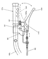
図2(a)は、本実施の形態1における歩行型耕耘機1の転輪部80の正面図であり、図2(b)は、転輪部80の左側面図であり、図2(c)は、転輪部80を構成する支持アーム82の根元部の部分拡大図であり、図2(d)は、支持アーム82の根元部が回動可能に連結されている機体フレーム10を構成する左側の本体プレート10Lの部分拡大図である。尚、図2(b)では、転輪部80が、移動用の姿勢にあるとき、及び耕耘用の姿勢にあるときを共に実線で示し、移動用の姿勢から耕耘用の姿勢に移る過程において、支持アームピン82aが凹部から抜け出た状態を二点鎖線で示している。
FIG. 2 (a) is a front view of the
図1に示す通り、本実施の形態1の歩行型耕耘機1は、(1)正面視で互いに反対方向に向けて略L字形状に折り曲げられた、歩行型耕耘機1の機体前後方向に長い左右一対の本体プレート10L、10R(図2(a)参照)が一定の隙間11を隔てて互いに締結部品(図示省略)で固定されてなる機体フレーム10と、(2)機体フレーム10の上面に固定されたエンジン20と、(3)エンジン20の上方に配置された燃料タンク30と、(4)エンジン20の後方に配置され後ろ上がりで、平面視で左右後方に略V字状に延びた操作用ハンドル40と、(5)機体フレーム10の後端部にその前側中央部が固定され、その後ろ側中央部が作業機取り付け部50に固定されると共に、エンジン20からの駆動力により複数の耕耘爪60を回動させるミッションケースを含む耕耘装置70と、(6)作業機取り付け部50に高さが調節可能に装着され、機体の前進スピードを抑える働きをする抵抗棒55と、(7)機体フレーム10の前方側に回動自在に設けられ、移動用の姿勢と耕耘用の姿勢を切替可能な転輪部80と、を備えた構成である。尚、図1では、移動用の姿勢にある転輪部80を二点鎖線で表し、耕耘用の姿勢にある転輪部80を実線で表した。
As shown in FIG. 1, the walking
また、転輪部80は、(1)回転車輪81と、(2)先端側で回転車輪81を回動自在に支持し、根本側で左右一対の左側の本体プレート10Lと右側の本体プレート10Rの対向する隙間11に挿入されて、左右一対の本体プレート10L、10R、即ち、機体フレーム10に対して回動可能に連結された支持アーム82と、を有している。
Further, the
また、支持アーム82の根本側には、図2(a)に示す通り、回転車輪81の回動軸81aと平行に配置された支持アームピン82aが、左右両側に突き出した状態で当該根本側に固定されており、更に、図2(b)、図2(c)に示す通り、支持アームピン82aを基準として回転車輪81と反対側に長孔82bが設けられている。
Further, on the root side of the
一方、機体フレーム10を構成する左側の本体プレート10L及び右側の本体プレート10Rには、図2(a)に示す通り、支持アームピン82aと平行であって、且つ長孔82bにスライド移動可能に挿入された固定ピン10aが、左右両側に突き出した状態で固定されており、図2(d)に示す通り、固定ピン10aから見て前方斜め上側に、耕耘用姿勢における支持アームピン82aを保持可能な第1凹部12aが形成されており、且つ、固定ピン10aから見て下方斜め前側に、移動用姿勢における支持アームピン82aを保持可能な第2凹部12bが形成されている。
On the other hand, as shown in FIG. 2 (a), the left
また、支持アームピン82aの先端部と固定ピン10aの先端部は引っ張りばね部材15により連結されており、支持アームピン82aは、固定ピン10a側に引っ張られる力が常時作用する構成である。
Further, the distal end portion of the
そして、転輪部80が移動用の姿勢にあるときは、支持アーム82は、引っ張りばね部材15の復元力(縮まろうとする力)により、第2凹部12bに支持アームピン82aが保持された状態にあり、また、転輪部80が耕耘用の姿勢にあるときは、支持アーム82は、引っ張りばね部材15の復元力により、第1凹部12aに支持アームピン82aが保持された状態にある構成である。
When the
また、抵抗棒55又は耕耘爪60を地面Gに接触させた状態から接触させた方を支点として操作用ハンドル40を持ち上げることにより、回転車輪81が接地した状態から、当該支点が更に地面Gから所定距離持ち上げられた状態までの範囲では、移動用の姿勢における支持アームピン82aは、固定ピン10aに対して、地面Gを基準として、距離d1だけ前方側に位置している構成であり(図2(b)参照)、且つ、抵抗棒55及び耕耘爪60を地面Gに接触させた状態では、耕耘用の姿勢における支持アームピン82aは、固定ピン10aに対して、地面Gを基準として、距離d2だけ上方側に位置している構成である。
Further, by lifting the operation handle 40 with the
以上の構成により、例えば、作業者が手動で、転輪部80を、移動用の姿勢から耕耘用の姿勢に切り替える際の動作について、主として図2(b)〜図2(d)を参照しながら説明する。
With the above configuration, for example, with reference to FIGS. 2 (b) to 2 (d), the operator manually switches the
このとき、初期状態において、支持アームピン82aが第2凹部12bに保持されているので、作業者は、支持アーム82を引っ張りばね部材15の復元方向に対抗する方向、即ち、支持アームピン82aが、下方斜め前側に向けて開口された第2凹部12bから抜け出す方向にスライド移動させる(図2(b)の矢印A参照)。これにより、固定ピン10aが長孔82b内を相対的に上方斜め後ろ側に向けて移動すると共に、支持アームピン82aが第2凹部12bにおける保持状態から開放される。そこで、作業者は、支持アーム82を前方側に持ち上げる。これにより、支持アーム82は、固定ピン10aを回動中心として、引っ張りばね部材15の復元力の作用を受けて支持アームピン82aが左右一対の本体プレート10L、10Rの前端部の湾曲部13(図2(d)参照)に沿いながら矢印B方向に移動して(図2(b)参照)、最終的に、支持アームピン82aが、左右一対の本体プレート10L、10Rの前端部の突起部14(図2(d)参照)を乗り越えた後、引っ張りばね部材15の復元力の作用を受けて、前方斜め上側に向けて開口された第1凹部12aの奥側に引き込まれて、第1凹部12aに保持される。
At this time, since the
これにより、転輪部80が耕耘位置にあるときに支持アームピン82aが、第1凹部12aに引っ張りばね部材15の作用により保持されるので、耕耘作業時における振動等により第1凹部12aから支持アームピン82aが外れ難い。
Thus, since the
また、これにより、移動時(転輪部80が移動用の姿勢にあるとき)には支持アーム82を前傾斜姿勢にすることで移動姿勢が良好となり、耕耘作業時(転輪部80が耕耘用の姿勢にあるとき)には支持アーム82を前上がり傾斜姿勢にすることで、転輪部80を耕耘作業域外に保持し易い。
In addition, by this, when moving (when the
次に、図3〜図5を用いて、操作用ハンドル40のグリップ部41に設けられたデッドマンクラッチレバー100のレバー牽制機構について説明する。
Next, a lever check mechanism of the deadman
図3は、本実施の形態の歩行型耕耘機1の左右方向に延びる操作用ハンドル40の左側のハンドル40Lの端部に設けられたグリップ部41L近傍の左側面拡大図である。図4(a)は、図3に示すグリップ部41L近傍の平面図であると共に、牽制プレートの作用によりデッドマンクラッチレバーの動作が牽制されている状態(牽制状態)を示した図である。また、図4(b)は、図3に示すグリップ部41L近傍の平面図であると共に、牽制プレートの作用によりデッドマンクラッチレバーの動作が牽制されていない状態(牽制解除状態)を示した図である。
FIG. 3 is an enlarged left side view of the vicinity of the
また、図5(a)〜図5(c)は、図4(a)に示すグリップ部41を背面側から見た図であり、牽制プレートの動作を示す部分拡大図である。図5(a)は、デッドマンクラッチレバーが牽制状態にあり、デッドマンクラッチレバーが握れない状態を示し、図5(b)、図5(c)は、デッドマンクラッチレバーが牽制状態から開放されて、デッドマンクラッチレバーが握られた状態を示している。 5 (a) to 5 (c) are views of the grip portion 41 shown in FIG. 4 (a) as seen from the back side, and are partially enlarged views showing the operation of the check plate. FIG. 5A shows a state where the deadman clutch lever is in a restrained state and the deadman clutch lever cannot be gripped. FIGS. 5B and 5C show that the deadman clutch lever is released from the restrained state, The deadman clutch lever is shown in a gripped state.
図3に示す通り、左側のハンドル40Lに固定されたクラッチホルダー90には、レバー支点部91を介して、回動可能にデッドマンクラッチレバー100が設けられている。デッドマンクラッチレバー100の前端部には、クラッチケーブル92の端部が連結されており、作業者がデッドマンクラッチレバー100を握ると、クラッチケーブル92が後方に引っ張られて、クラッチ(図示省略)が「入」状態となり、駆動力が伝達される構成である。また、作業者がデッドマンクラッチレバー100を握ることをやめると、クラッチケーブル92が引き戻されて、クラッチは「入」状態から「切」状態になり、駆動力が伝達されなくなる構成である。
As shown in FIG. 3, a deadman
本実施の形態で、クラッチ(図示省略)は、エンジン20とミッションケースとの間のテンションローラ(クラッチ)(図示省略)の入り切り状態を切り替えるものである。
In the present embodiment, a clutch (not shown) switches the on / off state of a tension roller (clutch) (not shown) between the
また、クラッチホルダー90には、図4(a)に示す通り、平面視で略L字状に曲げられた操作ピン93が、機体の左右方向にスライド移動可能に保持されており、操作ピン93は、その屈曲部の近傍において、平面視で略L字状であり、且つ背面視でも略L字状(図5(a)参照)の牽制プレート110を、平面視で略L字状の短辺部111において貫通した状態で当該牽制プレート110を固定している。
As shown in FIG. 4A, the
牽制プレート110は、平面視で、略L字状の長辺部112が(図4(a)参照)、操作ピン93の機体左右方向に延びる部分に平行に配置されており、その長辺部112が、図5(a)に示す通り、背面視で、下方に屈曲した先端部112aと、短辺部111に隣接した根元部112bを有している。また、牽制プレート110の長辺部112の根元部112bには、デッドマンクラッチレバー100の上端縁部100aの左右方向の幅よりも広い幅の凹部からなる牽制解除部113が設けられている。
The
また、クラッチホルダー90は、図5(a)に示す通り、背面視で、左側のハンドル40Lの上面側に覆いかぶさると共に、その両端側が下方に向けて平行に延びている。そして、操作ピン93が、平行に延びたクラッチホルダー90を貫通すると共に、操作ピン93の略L字状に曲げられた短辺部93aが、クラッチホルダー90から機体内側に、即ち、作業者がグリップ部41Lを左手で握ったときに親指がくる側に飛び出すべく、圧縮ばねである付勢スプリング94の復元力(伸びようとする力)により常時付勢されている。付勢スプリング94は、コイル形状に巻かれた円筒形状を呈しており、その中央の開口部に操作ピン93が挿入されていて、操作ピン93の外周に固定された座金95と、操作ピン93により貫通されたクラッチホルダー90の内壁面との間に配置されている。
Further, as shown in FIG. 5A, the
次に、図5(a)〜図5(c)を用いて、デッドマンクラッチレバー100のレバー牽制機構の動作について説明する。
Next, the operation of the lever check mechanism of the deadman
通常は、デッドマンクラッチレバー100は、図5(a)に示す通り、牽制状態にある。即ち、操作ピン93は、圧縮ばねである付勢スプリング94の復元力の作用により、操作ピン93の略L字状に曲げられた短辺部93a側が、図中の右側に突き出した状態で保持されている。それにより、操作ピン93に固定されている牽制プレート110も同様に右側に突き出した状態にあり、その牽制プレート110の先端部112aが、デッドマンクラッチレバー100の上端縁部100aの直ぐ上に位置している。この状況下で、作業者が、デッドマンクラッチレバー100を握ろうとしても、先端部112aがデッドマンクラッチレバー100の上端縁部100aに当たり、デッドマンクラッチレバー100の動きが牽制されて、クラッチ(図示省略)は「切」状態(駆動力が伝達されない状態)を維持する。
Normally, the deadman
次に、作業者が、左側のグリップ部41Lの上に左手を乗せたままの状態で、操作ピン93の短辺部93aを左手の親指で押さえ込むことにより、操作ピン93が図5(b)の矢印C方向にスライド移動すると共に、牽制プレート110の先端部112aも同様に矢印C方向にスライド移動する。
Next, the operator presses the
これによって、牽制プレート110の牽制解除部113の凹部が、デッドマンクラッチレバー100の上端縁部100aの上方に移動するので、この状況下で、即ち、作業者が、操作ピン93の短辺部93aを左手の親指で押さえたまま、更に、デッドマンクラッチレバー100を握ると、デッドマンクラッチレバー100の上端縁部100aが牽制解除部113の凹部に進入して、クラッチ(図示省略)は「入」状態(駆動力が伝達される状態)となる。
As a result, the concave portion of the
尚、その後、作業者が、デッドマンクラッチレバー100を握ったまま、操作ピン93の短辺部93aを左手の親指で押さえ込むことをやめたとき、図5(c)に示す通り、付勢スプリング94の復元力の作用により、操作ピン93が矢印D方向に移動すると共に、牽制プレート110の先端部112aも同様に移動して、デッドマンクラッチレバー100の上端縁部100aの側面部100bに当たり止る。
After that, when the operator stops pressing the
そして、作業者が、デッドマンクラッチレバー100を握ることを止めると、デッドマンクラッチレバー100の上端縁部100aが下方に移動して、牽制プレート110の先端部112aがデッドマンクラッチレバー100の上端縁部100aの側面部100bに邪魔されることが無いので、操作ピン93は更に矢印D方向に移動し、操作ピン93の外周に固定された座金95が、クラッチホルダー90の内壁面に当たることにより移動を停止して、図5(a)に示す状態になる。
When the worker stops gripping the deadman
次に、図6を用いて、ミッションケース200の内部構成を説明する。
Next, the internal configuration of the
図6は、ミッションケース200の内部構成を示す背面側から見た概略の断面図である。
FIG. 6 is a schematic cross-sectional view showing the internal configuration of the
図6に示す通り、ミッションケース200は、エンジン20からの駆動力を受け取る入力軸210と、入力軸210からの駆動力を受けて複数の耕耘爪60を回転させる出力軸220と、入力軸210の回転方向を正回転のまま出力軸220に伝達するか、あるいは逆回転させて出力軸220に伝達するかの切り替えを行う切り替えクラッチ230を備えている。
As shown in FIG. 6, the
また、切り替えクラッチ230は、入力軸210上のほぼ中央部にスライド可能にスプライン接続されており、当該切り替えクラッチ230のスライド方向の左右両端部には、第1クラッチ爪230aと第2クラッチ爪230bが設けられている。
The switching
更に、入力軸210上の片側には、切り替えクラッチ230の第1クラッチ爪230aと連結可能な爪部材が設けられた第1スプロケット240が周動自在に配置されている。また、入力軸210上であって、第1スプロケット240とは反対側には、切り替えクラッチ230の第2クラッチ爪230bと連結可能な爪部材が設けられた第1ギア250が周動自在に配置されている。
Further, on one side of the
また、切り替えクラッチ230を入力軸210上でスライドさせるシフタ260が、右側のケーシング300Rを貫通して設けられている。シフタ260は、第1スプロケット240または第1ギア250のどちらかに連結されるべくバネにて付勢されている。
Further, a
また、ミッションケース200内には、入力軸210に平行に中間軸265が回動自在に配置されている。中間軸265上には、入力軸210上の第1スプロケット240からの駆動力を、第1チェーン241を介して受ける第2スプロケット242が固定されている。また、中間軸265上には、入力軸210上の第1ギア250からの駆動力を受ける第2ギア251が固定されている。また、中間軸265上の第2スプロケット242と第2ギア251の間には、第3スプロケット270が固定されており、第2スプロケット242を介して伝達された正回転の駆動力、又は第2ギヤ251を介して伝達された逆回転の駆動力を、第2チェーン271を介して、出力軸220に固定された第4スプロケット272に伝達する構成である。
In the
以上の構成により、シフタ260を操作して、切り替えクラッチ230の第1クラッチ爪230aを第1スプロケット240の爪部材と連結させることにより、入力軸210から入力された駆動力が、第1スプロケット240、第2スプロケット242、第3スプロケット270、及び第4スプロケット272を経て、回転方向を変えることなく出力軸220に伝達される。
With the above configuration, by operating the
また、シフタ260を操作して、切り替えクラッチ230の第2クラッチ爪230bを第1ギア250の爪部材と連結させることにより、入力軸210から入力された駆動力が、第1ギア250、第2ギア251、第3スプロケット270、及び第4スプロケット272を経て、回転方向を変えて出力軸220に伝達される。
Further, by operating the
これにより、軸の回転方向を逆転させることが、2軸で実現出来るので、軽量化や低コスト化が図れる。 As a result, since the rotation direction of the shaft can be reversed with two shafts, weight reduction and cost reduction can be achieved.
尚、ミッションケース200を構成する左右一対のケーシング200L、200Rは、板金製である。入力軸210用の内装軸受け部材211、212、及び、中間軸265用の内装軸受け部材261、262を固定するハウジングプレート280が、左右一対のケーシング200L、200Rの内壁に溶接固定されている。また、左右一対のケーシング200L、200Rの外面上の、ハウジングプレート280の軸受け部の内周に対応する部位を囲む位置には、円状の補強用リブが設けられている。
The pair of left and
この補強用リブを設けることにより、ハウジングプレート280の溶接による、左右一対のケーシング200L、200Rの軸受け部に対応する部位の歪み、ねじれ等を抑えることが出来る。
By providing this reinforcing rib, it is possible to suppress distortion, twisting, and the like of portions corresponding to the bearing portions of the pair of left and
尚、上記実施の形態では、金属製の操作ピン93の短辺部93aを作業者が指で直接押さえる構成について説明したが、これに限らず例えば、作業者が、親指で触れる、操作ピン93の短辺部93aにゴム製のチューブ等を被せたり、或いは、短辺部93a自体をゴム部材に変えて、操作ピン93の端部に取り付けた構成であっても良い。これにより、指で触れる箇所が滑りにくく、確実に押さえることが出来る。
In the above-described embodiment, the configuration in which the operator directly presses the
本発明の歩行型耕耘機によれば、耕耘作業時において振動等により、車輪が耕耘作業時の位置から移動時の位置に動いてしまうことを従来に比べて少なく出来るという効果を発揮し、歩行型耕耘機として有用である。 According to the walking type tiller of the present invention, the effect of reducing the movement of the wheel from the position at the time of the plowing work to the position at the time of the movement due to vibration or the like during the plowing work can be achieved. It is useful as a type cultivator.
1 歩行型耕耘機
10 機体フレーム
10a 固定ピン
10L 左側の本体プレート
10R 右側の本体プレート
12a 第1凹部
12b 第2凹部
13 湾曲部
14 突起部
15 引っ張りばね部材
20 エンジン
30 燃料タンク
40 操作用ハンドル
50 作業機取り付け部
55 抵抗棒
60 耕耘爪
70 耕耘装置
80 転輪部
81 回転車輪
81a 回動軸
82 支持アーム
82a 支持アームピン
82b 長孔
DESCRIPTION OF
13 curved parts
14
Claims (3)
前記機体フレームに固定された駆動装置と、
前記駆動装置の後方に配置された操作用ハンドルと、
前記機体フレームに固定され、前記駆動装置からの駆動力により複数の耕耘爪を回動させる耕耘装置と、
前記耕耘装置の後方に配置された抵抗棒と、
前記機体フレームの前方側に回動自在に設けられ、地面に接地する移動用の姿勢と地面から離間する耕耘用の姿勢を切替可能な転輪部と、を備えた歩行型耕耘機であって、
前記転輪部は、
回転車輪と、
一端側で前記回転車輪を回動自在に支持し、他端側で前記機体フレームに対して回動可能に連結された支持アームと、を有し、
前記支持アームの前記他端側には、前記回転車輪の回動軸と平行な支持アームピンが固定されると共に、前記支持アームピンを基準として前記回転車輪と反対側に長孔が設けられており、
前記機体フレームには、
前記支持アームピンと平行であって且つ前記長孔に挿入された固定ピンが固定され、
前記固定ピンから見て前方側に、前記支持アームピンを保持可能で前方斜め上側に向けて開口された第1凹部が形成され、
前記固定ピンから見て下方側に、前記支持アームピンを保持可能で下方斜め前側に向けて開口された第2凹部が形成されており、
前記第2凹部は、側面視で前記第1凹部より下方で且つ後方に位置しており、
前記支持アームピンと前記固定ピンは引っ張りばね部材により連結されており、
前記転輪部が前記移動用の姿勢にあるときは、前記支持アームは、前記引っ張りばね部材の復元力により、前記第2凹部に前記支持アームピンが保持された状態にあり、
前記転輪部が前記耕耘用の姿勢にあるときは、前記支持アームは、前記引っ張りばね部材の復元力により、前記第1凹部に前記支持アームピンが保持された状態にあり、
前記機体フレームの前端部には、機体後方に向かって湾曲する湾曲部が前記第1凹部と前記第2凹部の間にわたって形成されており、且つ、前記湾曲部の一端部と前記第1凹部の間と、前記湾曲部の他端部と前記第2凹部の間にそれぞれ突起部が形成されており、
前記支持アームピンは前記湾曲部に沿って前記第1凹部と前記第2凹部間を移動する構成とすることを特徴とする歩行型耕耘機。 The fuselage frame,
A driving device fixed to the fuselage frame;
An operation handle disposed behind the drive device;
A tilling device fixed to the body frame and rotating a plurality of tilling claws by a driving force from the driving device;
A resistance bar arranged behind the tillage device;
A walk-type field cultivator provided on the front side of the body frame so as to be freely rotatable, and having a rolling part capable of switching between a posture for moving to contact the ground and a posture for cultivating separated from the ground. ,
The rolling part is
Rotating wheels,
A support arm that rotatably supports the rotating wheel on one end side and is rotatably connected to the body frame on the other end side;
A support arm pin parallel to the rotation axis of the rotating wheel is fixed to the other end side of the support arm, and a long hole is provided on the opposite side of the rotating wheel with respect to the support arm pin.
In the aircraft frame,
A fixing pin that is parallel to the support arm pin and inserted into the elongated hole is fixed,
A first recess is formed on the front side as viewed from the fixing pin, and can hold the support arm pin and is opened obliquely upward on the front side .
A second recess is formed on the lower side as viewed from the fixing pin, and can hold the support arm pin and is opened toward the lower diagonal front side .
The second recess is located below and behind the first recess in a side view,
The support arm pin and the fixing pin are connected by a tension spring member,
When the rolling wheel portion is in the moving posture, the support arm is in a state where the support arm pin is held in the second recess by the restoring force of the tension spring member,
When the rolling part is in the position for tillage, the support arm is in a state where the support arm pin is held in the first recess by the restoring force of the tension spring member,
A curved portion that curves toward the rear of the fuselage is formed at the front end portion of the fuselage frame between the first concave portion and the second concave portion, and one end portion of the curved portion and the first concave portion are formed. A protrusion is formed between the other end of the curved portion and the second recess,
The walking type tiller is characterized in that the support arm pin is configured to move between the first recess and the second recess along the curved portion .
前記抵抗棒及び前記耕耘爪を前記地面に接触させた状態では、前記耕耘用の姿勢における前記支持アームピンは、前記固定ピンに対して、前記地面を基準として、上方側に位置している、ことを特徴とする請求項1に記載の歩行型耕耘機。 The fulcrum is further lifted from the ground by a predetermined distance from the state in which the operation wheel is lifted with the rotating wheel in contact with the resistance bar or the tilling claw in contact with the ground from the contacted state. In the range up to the state, the support arm pin in the moving posture is located on the front side with respect to the fixed pin with respect to the ground,
In a state where the resistance rod and the tilling claw are in contact with the ground, the support arm pin in the tilling posture is positioned on the upper side with respect to the fixed pin with respect to the ground. The walking type tiller according to claim 1, wherein
前記ミッションケースは、前記駆動装置からの駆動力を受け取る入力軸と、該入力軸からの駆動力を受けて前記複数の耕耘爪を回転させる出力軸と、前記入力軸の回転方向を正回転のまま出力軸に伝達するか、あるいは逆回転させて前記出力軸に伝達するかの切り替えを行う切り替えクラッチを備え、 The transmission case includes an input shaft that receives a driving force from the driving device, an output shaft that receives the driving force from the input shaft and rotates the plurality of tilling claws, and a rotational direction of the input shaft that rotates forward. A switching clutch for switching whether to transmit to the output shaft as it is or to reversely transmit to the output shaft,
該切り替えクラッチは、前記入力軸上のほぼ中央部にスライド可能にスプライン接続されており、該切り替えクラッチのスライド方向の左右両端部には、第1クラッチ爪と第2クラッチ爪を設け、 The switching clutch is slidably connected to a substantially central portion on the input shaft, and a first clutch pawl and a second clutch pawl are provided at both left and right ends in the sliding direction of the switching clutch,
前記入力軸上の片側には、切り替えクラッチの第1クラッチ爪と連結可能な第1スプロケットを周動自在に配置し、前記入力軸上であって、前記第1スプロケットの反対側に、前記切り替えクラッチの第2クラッチ爪と連結可能な第1ギアを周動自在に配置し、 A first sprocket that can be connected to a first clutch pawl of a switching clutch is disposed on one side of the input shaft so as to be capable of rotating, and the switching is performed on the input shaft on the opposite side of the first sprocket. A first gear connectable with the second clutch pawl of the clutch is arranged to be freely rotatable,
前記入力軸に平行に中間軸を回動自在に配置し、該中間軸上には、前記第1スプロケットからの駆動力を、第1チェーンを介して受ける第2スプロケットが固定されると共に、前記入力軸上の前記第1ギアからの駆動力を受ける第2ギアが固定され、前記第2スプロケットと前記第2ギアの間には、第3スプロケットが固定され、前記第2スプロケットを介して伝達された正回転の駆動力、又は前記第2ギヤを介して伝達された逆回転の駆動力を、第2チェーンを介して、前記出力軸に固定された第4スプロケットに伝達する構成とする請求項1又は請求項2記載の歩行型耕耘機。 An intermediate shaft is rotatably arranged parallel to the input shaft, and a second sprocket that receives the driving force from the first sprocket via the first chain is fixed on the intermediate shaft, A second gear that receives driving force from the first gear on the input shaft is fixed, and a third sprocket is fixed between the second sprocket and the second gear, and is transmitted via the second sprocket. The forward rotation driving force transmitted or the reverse rotation driving force transmitted through the second gear is transmitted to the fourth sprocket fixed to the output shaft through the second chain. The walking type tiller according to claim 1 or 2.
Priority Applications (3)
| Application Number | Priority Date | Filing Date | Title |
|---|---|---|---|
| JP2014069232A JP6233140B2 (en) | 2014-03-28 | 2014-03-28 | Walk-type field cultivator |
| FR1552576A FR3018992B1 (en) | 2014-03-28 | 2015-03-26 | GROWING GROWER |
| CN201520181413.4U CN204721805U (en) | 2014-03-28 | 2015-03-27 | Legged ploughing machine |
Applications Claiming Priority (1)
| Application Number | Priority Date | Filing Date | Title |
|---|---|---|---|
| JP2014069232A JP6233140B2 (en) | 2014-03-28 | 2014-03-28 | Walk-type field cultivator |
Publications (3)
| Publication Number | Publication Date |
|---|---|
| JP2015188403A JP2015188403A (en) | 2015-11-02 |
| JP2015188403A5 JP2015188403A5 (en) | 2017-02-02 |
| JP6233140B2 true JP6233140B2 (en) | 2017-11-22 |
Family
ID=54106032
Family Applications (1)
| Application Number | Title | Priority Date | Filing Date |
|---|---|---|---|
| JP2014069232A Active JP6233140B2 (en) | 2014-03-28 | 2014-03-28 | Walk-type field cultivator |
Country Status (3)
| Country | Link |
|---|---|
| JP (1) | JP6233140B2 (en) |
| CN (1) | CN204721805U (en) |
| FR (1) | FR3018992B1 (en) |
Families Citing this family (3)
| Publication number | Priority date | Publication date | Assignee | Title |
|---|---|---|---|---|
| JP6853127B2 (en) * | 2017-06-28 | 2021-03-31 | 株式会社クボタ | Walking work machine |
| CN107231829B (en) * | 2017-06-30 | 2019-10-18 | 王良仁 | A kind of reciprocal shovel type cultivator |
| JP6840789B2 (en) * | 2019-06-24 | 2021-03-10 | 株式会社クボタ | Walking type management machine |
Family Cites Families (8)
| Publication number | Priority date | Publication date | Assignee | Title |
|---|---|---|---|---|
| US4164983A (en) * | 1978-02-21 | 1979-08-21 | Deere & Company | Walk-behind filler with combined drag stake and wheel |
| JPS58179283U (en) * | 1982-05-26 | 1983-11-30 | ニユ−デルタ工業株式会社 | Moving wheel of axle work shape management machine |
| ES2203695T3 (en) * | 1995-05-24 | 2004-04-16 | Yanmar Agricultural Equipment Co., Ltd. | AGRICULTURAL MACHINE. |
| JPH09207830A (en) * | 1996-02-07 | 1997-08-12 | Shigeki Sano | Operating handle mounting structure for tiller |
| JP4181097B2 (en) * | 2004-08-23 | 2008-11-12 | 本田技研工業株式会社 | Front rotary work machine |
| ITRE20070097A1 (en) * | 2007-09-06 | 2009-03-07 | Eurosystems S P A | IMPROVED AGRICULTURAL TOOL |
| FR2960382B1 (en) * | 2010-06-01 | 2012-07-20 | Pubert Henri Sas | REMOVABLE TRANSPORT WHEEL EQUIPMENT |
| ITRE20110069A1 (en) * | 2011-09-16 | 2013-03-17 | Eurosystems S P A | IMPROVED AGRICULTURAL TOOL |
-
2014
- 2014-03-28 JP JP2014069232A patent/JP6233140B2/en active Active
-
2015
- 2015-03-26 FR FR1552576A patent/FR3018992B1/en active Active
- 2015-03-27 CN CN201520181413.4U patent/CN204721805U/en not_active Expired - Fee Related
Also Published As
| Publication number | Publication date |
|---|---|
| CN204721805U (en) | 2015-10-28 |
| FR3018992A1 (en) | 2015-10-02 |
| JP2015188403A (en) | 2015-11-02 |
| FR3018992B1 (en) | 2019-08-02 |
Similar Documents
| Publication | Publication Date | Title |
|---|---|---|
| JP6233140B2 (en) | Walk-type field cultivator | |
| JP5208078B2 (en) | Walking type management machine | |
| JP2011063224A (en) | Walking type plant husbandry machine | |
| JP2015188403A5 (en) | ||
| JP2008132930A (en) | Operation mechanism of working machine | |
| JP4484917B2 (en) | Handle structure of walking work machine | |
| JP6162619B2 (en) | Armrest | |
| JP4764285B2 (en) | Operation lever device | |
| JP2008213729A (en) | Clutch operating device in walking working machine | |
| JP2012065585A (en) | Walking-type farming implement | |
| JP2015128396A (en) | Walk-behind working machine | |
| JP4764286B2 (en) | Operation lever device | |
| JP2007166945A (en) | Mobile agricultural machine | |
| JP2010220575A (en) | Walking type mobile agricultural machine | |
| JP5289689B2 (en) | Walking type management machine | |
| JP2008062931A (en) | Hand-operated tractor | |
| JP5466540B2 (en) | Management machine | |
| JP4344254B2 (en) | Stopper device | |
| JP4718377B2 (en) | Clutch operating structure of walking type work machine | |
| JP2020039299A (en) | Axle type electric walk management device | |
| JP2019189055A (en) | Walking type control machine | |
| JP2007006739A (en) | Walking type working machine | |
| JPH09290776A (en) | Hand-tractor operating device | |
| JP2011186956A (en) | Operation lever of working machine | |
| JP2015097491A (en) | Walk-management machine |
Legal Events
| Date | Code | Title | Description |
|---|---|---|---|
| A521 | Written amendment |
Free format text: JAPANESE INTERMEDIATE CODE: A523 Effective date: 20161219 |
|
| A621 | Written request for application examination |
Free format text: JAPANESE INTERMEDIATE CODE: A621 Effective date: 20161219 |
|
| A131 | Notification of reasons for refusal |
Free format text: JAPANESE INTERMEDIATE CODE: A131 Effective date: 20170627 |
|
| A977 | Report on retrieval |
Free format text: JAPANESE INTERMEDIATE CODE: A971007 Effective date: 20170630 |
|
| A521 | Written amendment |
Free format text: JAPANESE INTERMEDIATE CODE: A523 Effective date: 20170822 |
|
| TRDD | Decision of grant or rejection written | ||
| A01 | Written decision to grant a patent or to grant a registration (utility model) |
Free format text: JAPANESE INTERMEDIATE CODE: A01 Effective date: 20170926 |
|
| A61 | First payment of annual fees (during grant procedure) |
Free format text: JAPANESE INTERMEDIATE CODE: A61 Effective date: 20171009 |
|
| R150 | Certificate of patent or registration of utility model |
Ref document number: 6233140 Country of ref document: JP Free format text: JAPANESE INTERMEDIATE CODE: R150 |