JP6230724B2 - Hinge and hinge bracket - Google Patents
Hinge and hinge bracket Download PDFInfo
- Publication number
- JP6230724B2 JP6230724B2 JP2016559456A JP2016559456A JP6230724B2 JP 6230724 B2 JP6230724 B2 JP 6230724B2 JP 2016559456 A JP2016559456 A JP 2016559456A JP 2016559456 A JP2016559456 A JP 2016559456A JP 6230724 B2 JP6230724 B2 JP 6230724B2
- Authority
- JP
- Japan
- Prior art keywords
- door
- side member
- main body
- joint
- hinge
- Prior art date
- Legal status (The legal status is an assumption and is not a legal conclusion. Google has not performed a legal analysis and makes no representation as to the accuracy of the status listed.)
- Active
Links
- 125000006850 spacer group Chemical group 0.000 claims description 10
- 239000011521 glass Substances 0.000 description 7
- 239000002184 metal Substances 0.000 description 2
- 239000011347 resin Substances 0.000 description 2
- 229920005989 resin Polymers 0.000 description 2
- NIXOWILDQLNWCW-UHFFFAOYSA-N acrylic acid group Chemical group C(C=C)(=O)O NIXOWILDQLNWCW-UHFFFAOYSA-N 0.000 description 1
- 230000000694 effects Effects 0.000 description 1
- 230000002265 prevention Effects 0.000 description 1
Images


Classifications
-
- E—FIXED CONSTRUCTIONS
- E05—LOCKS; KEYS; WINDOW OR DOOR FITTINGS; SAFES
- E05D—HINGES OR SUSPENSION DEVICES FOR DOORS, WINDOWS OR WINGS
- E05D3/00—Hinges with pins
- E05D3/06—Hinges with pins with two or more pins
- E05D3/16—Hinges with pins with two or more pins with seven parallel pins and four arms
-
- E—FIXED CONSTRUCTIONS
- E05—LOCKS; KEYS; WINDOW OR DOOR FITTINGS; SAFES
- E05D—HINGES OR SUSPENSION DEVICES FOR DOORS, WINDOWS OR WINGS
- E05D5/00—Construction of single parts, e.g. the parts for attachment
- E05D5/02—Parts for attachment, e.g. flaps
- E05D5/0246—Parts for attachment, e.g. flaps for attachment to glass panels
-
- E—FIXED CONSTRUCTIONS
- E05—LOCKS; KEYS; WINDOW OR DOOR FITTINGS; SAFES
- E05D—HINGES OR SUSPENSION DEVICES FOR DOORS, WINDOWS OR WINGS
- E05D3/00—Hinges with pins
- E05D3/06—Hinges with pins with two or more pins
- E05D3/18—Hinges with pins with two or more pins with sliding pins or guides
- E05D3/186—Scissors hinges, with two crossing levers and five parallel pins
-
- E—FIXED CONSTRUCTIONS
- E05—LOCKS; KEYS; WINDOW OR DOOR FITTINGS; SAFES
- E05Y—INDEXING SCHEME RELATING TO HINGES OR OTHER SUSPENSION DEVICES FOR DOORS, WINDOWS OR WINGS AND DEVICES FOR MOVING WINGS INTO OPEN OR CLOSED POSITION, CHECKS FOR WINGS AND WING FITTINGS NOT OTHERWISE PROVIDED FOR, CONCERNED WITH THE FUNCTIONING OF THE WING
- E05Y2600/00—Mounting or coupling arrangements for elements provided for in this subclass
- E05Y2600/40—Mounting location; Visibility of the elements
- E05Y2600/41—Concealed
-
- E—FIXED CONSTRUCTIONS
- E05—LOCKS; KEYS; WINDOW OR DOOR FITTINGS; SAFES
- E05Y—INDEXING SCHEME RELATING TO HINGES OR OTHER SUSPENSION DEVICES FOR DOORS, WINDOWS OR WINGS AND DEVICES FOR MOVING WINGS INTO OPEN OR CLOSED POSITION, CHECKS FOR WINGS AND WING FITTINGS NOT OTHERWISE PROVIDED FOR, CONCERNED WITH THE FUNCTIONING OF THE WING
- E05Y2600/00—Mounting or coupling arrangements for elements provided for in this subclass
- E05Y2600/50—Mounting methods; Positioning
- E05Y2600/502—Clamping
-
- E—FIXED CONSTRUCTIONS
- E05—LOCKS; KEYS; WINDOW OR DOOR FITTINGS; SAFES
- E05Y—INDEXING SCHEME RELATING TO HINGES OR OTHER SUSPENSION DEVICES FOR DOORS, WINDOWS OR WINGS AND DEVICES FOR MOVING WINGS INTO OPEN OR CLOSED POSITION, CHECKS FOR WINGS AND WING FITTINGS NOT OTHERWISE PROVIDED FOR, CONCERNED WITH THE FUNCTIONING OF THE WING
- E05Y2600/00—Mounting or coupling arrangements for elements provided for in this subclass
- E05Y2600/60—Mounting or coupling members; Accessories therefore
- E05Y2600/626—Plates or brackets
-
- E—FIXED CONSTRUCTIONS
- E05—LOCKS; KEYS; WINDOW OR DOOR FITTINGS; SAFES
- E05Y—INDEXING SCHEME RELATING TO HINGES OR OTHER SUSPENSION DEVICES FOR DOORS, WINDOWS OR WINGS AND DEVICES FOR MOVING WINGS INTO OPEN OR CLOSED POSITION, CHECKS FOR WINGS AND WING FITTINGS NOT OTHERWISE PROVIDED FOR, CONCERNED WITH THE FUNCTIONING OF THE WING
- E05Y2900/00—Application of doors, windows, wings or fittings thereof
- E05Y2900/10—Application of doors, windows, wings or fittings thereof for buildings or parts thereof
- E05Y2900/13—Application of doors, windows, wings or fittings thereof for buildings or parts thereof characterised by the type of wing
- E05Y2900/132—Doors
-
- E—FIXED CONSTRUCTIONS
- E05—LOCKS; KEYS; WINDOW OR DOOR FITTINGS; SAFES
- E05Y—INDEXING SCHEME RELATING TO HINGES OR OTHER SUSPENSION DEVICES FOR DOORS, WINDOWS OR WINGS AND DEVICES FOR MOVING WINGS INTO OPEN OR CLOSED POSITION, CHECKS FOR WINGS AND WING FITTINGS NOT OTHERWISE PROVIDED FOR, CONCERNED WITH THE FUNCTIONING OF THE WING
- E05Y2900/00—Application of doors, windows, wings or fittings thereof
- E05Y2900/20—Application of doors, windows, wings or fittings thereof for furnitures, e.g. cabinets
Description
本発明は、本体に対して扉を開閉可能にするヒンジ及びこのヒンジが取り付けられるヒンジ用ブラケットに関する。 The present invention relates to a hinge capable of opening and closing a door with respect to a main body and a hinge bracket to which the hinge is attached.
ヒンジは、家具、建築物等の本体に取り付けられる本体側部材と、本体側部材に関節継手を介して回転可能に連結され、扉に取り付けられる扉側部材と、を備える。関節継手の構成は様々であるが、本体に対する扉の開き角度を大きくしたり、及び/又は扉を前方に移動させながら開き、本体と扉との干渉を避けるようにしたりするために、関節継手を少なくとも二つのリンクから構成するヒンジが知られている(例えば特許文献1参照)。 The hinge includes a main body side member attached to a main body such as furniture and a building, and a door side member rotatably connected to the main body side member via an joint joint and attached to the door. There are various configurations of joint joints, but in order to increase the opening angle of the door with respect to the main body and / or to open the door while moving the door forward to avoid interference between the main body and the door, the joint joint There is known a hinge comprising at least two links (see, for example, Patent Document 1).
特許文献1に記載のヒンジにおいて、各リンクの両端部は、本体側部材及び扉側部材に回転可能に連結される。本体側部材及び扉側部材には、関節継手の少なくとも一部が収容される凹部が設けられる。扉の閉じ位置において、関節継手は、扉側部材の凹部及び本体側部材の凹部に収容される。特許文献1に記載のヒンジによれば、扉の閉じ位置において、関節継手を隠すことができるので、扉のデザイン性が向上し、また防犯性が向上する。 In the hinge described in Patent Document 1, both ends of each link are rotatably connected to the main body side member and the door side member. The main body side member and the door side member are provided with a recess in which at least a part of the joint joint is accommodated. In the door closing position, the joint joint is accommodated in the recess of the door side member and the recess of the body side member. According to the hinge described in Patent Document 1, since the joint joint can be hidden at the door closing position, the design of the door is improved and the crime prevention is improved.
ところで、特許文献1に記載のヒンジにあっては、本体側部材及び扉側部材に関節継手の少なくとも一部が収容される凹部が設けられるので、本体側部材及び扉側部材の横幅(扉の厚さ方向の幅)が大きくなり易いという課題がある。このため、ガラス扉等の薄い扉の小口(扉の側面)に扉側部材を取り付けるのが困難である。 By the way, in the hinge of patent document 1, since the recessed part in which at least one part of an articulation joint is accommodated in the main body side member and the door side member is provided, the horizontal width of the main body side member and the door side member (the door There is a problem that the width in the thickness direction is likely to increase. For this reason, it is difficult to attach a door side member to the edge (side surface of the door) of a thin door such as a glass door.
そこで本発明は、ガラス扉等の薄い扉の小口に関節継手が収容される凹部を有する扉側部材を取り付けることが可能なヒンジ及びヒンジ用ブラケットを提供することを目的とする。 Then, an object of this invention is to provide the hinge and bracket for hinges which can attach the door side member which has a recessed part in which a joint joint is accommodated in the edge of thin doors, such as a glass door.
上記課題を解決するために、本発明の一態様は、本体に取り付けられる本体側部材と、扉に取り付けられ、前記本体側部材に関節継手を介して回転可能に連結され、前記関節継手の少なくとも一部が収容される凹部を有する扉側部材と、を備えるヒンジにおいて、前記扉側部材は、外郭部と、前記外郭部から張り出す第一挟持片と、前記扉の厚み方向における前記外郭部の範囲内において、前記第一挟持片との間で前記扉を前記厚さ方向に挟む第二挟持片と、を備えるヒンジである。 In order to solve the above-described problem, an aspect of the present invention includes a main body side member attached to a main body, a door attached to the door, and rotatably connected to the main body side member via an joint joint. And a door side member having a recess in which a part is accommodated, wherein the door side member includes an outer part, a first clamping piece projecting from the outer part, and the outer part in the thickness direction of the door And a second clamping piece that sandwiches the door in the thickness direction between the first clamping piece and the first clamping piece.
本発明の他の態様は、本体に取り付けられる本体側部材と、扉に取り付けられ、前記本体側部材に関節継手を介して回転可能に連結され、前記関節継手の少なくとも一部が収容される凹部を有する扉側部材本体と、を備えるヒンジの、前記扉側部材本体に取り付けられるブラケットであって、前記ブラケットは、前記扉側部材本体が収容され、締結部材によって前記扉側部材本体に締結される外郭部と、前記外郭部から張り出す第一挟持片と、前記扉の厚み方向における前記外郭部の範囲内において、前記第一挟持片との間で前記扉を前記厚さ方向に挟む第二挟持片と、を備えるヒンジ用ブラケットである。 Another aspect of the present invention is a body-side member attached to the body, a recess attached to the door, rotatably connected to the body-side member via a joint joint, and containing at least a part of the joint joint. A bracket that is attached to the door-side member main body, the bracket including the door-side member main body, and fastened to the door-side member main body by a fastening member. A first sandwiching piece projecting from the outer shell portion, and a first sandwiching piece sandwiched in the thickness direction between the first sandwiching piece within a range of the outer shell portion in the thickness direction of the door. It is a bracket for hinges provided with two clamping pieces.
本発明によれば、ガラス扉等の扉の小口に関節継手の少なくとも一部が収容される凹部を有する扉側部材又は扉側部材本体を取り付けることができる。 ADVANTAGE OF THE INVENTION According to this invention, the door side member or door side member main body which has a recessed part in which at least one part of an articulation joint is accommodated can be attached to the edge of a door, such as a glass door.
以下、添付図面に基づいて、本発明の実施形態のヒンジを詳細に説明する。ただし、本発明のヒンジは、種々の形態で具体化することができ、本明細書に記載される実施形態に限定されるものではない。本実施形態は、明細書の開示を十分にすることによって、当業者が発明の範囲を十分に理解できるようにする意図をもって提供されるものである。 Hereinafter, a hinge according to an embodiment of the present invention will be described in detail with reference to the accompanying drawings. However, the hinge of the present invention can be embodied in various forms, and is not limited to the embodiments described herein. This embodiment is provided with the intention of enabling those skilled in the art to fully understand the scope of the invention by fully disclosing the specification.
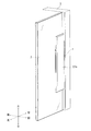
図1及び図2は、本発明の第一の実施形態のヒンジ1が取り付けられる建築物又は家具の斜視図を示す。図1は扉2の閉じ位置を示し、図2は扉2の開き位置を示す。なお、以下においては、説明の便宜上、特に明示がない限り、扉2を正面から見たときの方向、すなわち図1に示す上下、左右、前後の各方向を用いて、ヒンジ1の構成を説明する。もちろん、ヒンジ1はこのような配置に限られるものではない。
FIG.1 and FIG.2 shows the perspective view of the building or furniture to which the hinge 1 of 1st embodiment of this invention is attached. FIG. 1 shows the closed position of the
図2に示すように、ヒンジ1は、本体としての枠3の内面に取り付けられる本体側部材5と、扉2に取り付けられる扉側部材4と、を備える。枠3の内面には、例えば縦長長円形状の掘込み3aが設けられる。本体側部材5は、枠3の掘込み3aに収容される。扉側部材4は、関節継手6を介して本体側部材5に回転可能に連結される扉側部材本体7と、扉側部材本体7が収容されるブラケット8と、を備える。ブラケット8には、ガラス扉等の扉2が取り付けられる。
As shown in FIG. 2, the hinge 1 includes a main
関節継手6は、一端部が本体側部材5に回転可能に連結され、他端部が扉側部材本体7に第一補助リンク22を介して連結される第一リンク21と、一端部が扉側部材本体7に回転可能に連結され、他端部が第二補助リンク24を介して本体側部材5に連結される第二リンク23と、を備える。関節継手6は、図1に示す閉じ位置から図2に示す開き位置まで扉2が垂直軸の回りを略180°回転するのを許容する。関節継手6は、扉2と枠3との干渉を避けるように、扉2を前方に移動させながら扉2を開く。ヒンジ1には、扉2の上下、左右、前後方向の位置を微調整するための調整ねじ31a,31b〜33a,33bが組み込まれる(図3参照)。調整ねじ31a,31b〜33a,33bは、本体側部材5及び扉側部材本体7の上下方向の両端部の例えば縦長半長円形状のねじカバー34a〜34dで覆われる。
The
図3は、本発明の第一の実施形態のヒンジ1の分解斜視図を示す。上記のように、ヒンジ1は、本体側部材5と、本体側部材5に関節継手6を介して回転可能に連結される扉側部材本体7と、を備える。本体側部材5は、縦長であり、上下方向の両端部にフランジ5aを有する。フランジ5aには、通し孔が設けられる。本体側部材5は、ねじ等の締結部材(図示せず)によって枠3に取り付けられる。扉側部材本体7も、本体側部材5と同様に縦長であり、上下方向の両端部にフランジ7aを有する。フランジ7aには、通し孔が設けられる。扉側部材本体7は、ねじ等の締結部材25によってブラケット8に取り付けられる。ブラケット8の構成は後述する。
FIG. 3 shows an exploded perspective view of the hinge 1 of the first embodiment of the present invention. As described above, the hinge 1 includes the main
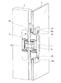
図4の水平断面図に示すように、関節継手6は、第一リンク21、第一補助リンク22、第二リンク23、第二補助リンク24を備える。第一リンク21は、その一端部が本体側部材5に回転可能に連結され、その他端部が第一補助リンク22に回転可能に連結される。第一補助リンク22は、その一端部が第一リンク21に回転可能に連結され、その他端部が扉側部材本体7に回転可能に連結される。第二リンク23は、その一端部が扉側部材本体7に回転可能に連結され、その他端部が第二補助リンク24に回転可能に連結される。第二補助リンク24は、その一端部が第二リンク23に回転可能に連結され、その他端部が本体側部材5に回転可能に連結される。第一リンク21の中央部と第二リンク23の中央部とは、互いに回転可能に連結される。関節継手6は、四節回転連鎖を2つ組み合わせて構成されており、合計7つの軸を持つ。
As shown in the horizontal sectional view of FIG. 4, the
なお、関節継手6の構成は上記実施形態に限定されるものではなく、他の構成を採用し得る。例えば、第一及び第二補助リンク22,24を設ける替わりに、第一リンク21の他端部を直接的に扉側部材本体7に回転可能にかつスライド可能に連結し、第二リンク23の他端部を直接的に本体側部材5に回転可能にかつスライド可能に連結することもできる。この場合、関節継手6は、合計5つの軸を持つ。また、第一及び第二補助リンク22,24を設ける替わりに、第一リンク21の両端部を直接的に本体側部材5及び扉側部材本体7に回転可能にかつスライド可能に連結し、第二リンク23の両端部を直接的に本体側部材5及び扉側部材本体7に回転可能に連結することもできる。第一リンク21と第二リンク23とは互いに回転可能に連結される。この場合、関節継手6は、合計5つの軸を持つ。さらに、関節継手を軸74の回りを回転するアーム73から構成することができる(図10及び図11参照)。この場合、関節継手は1つの軸74を持つ。一軸タイプの関節継手については後述する。
In addition, the structure of the
図4に示すように、本体側部材5には、箱形状の凹部5bが設けられていて、この凹部5bに関節継手6の一部が収容される。同様に、扉側部材本体7には、箱形状の凹部7bが設けられていて、この凹部7bに関節継手6の一部が収容される。図1に示す扉2の閉じ位置において、本体側部材5と扉側部材本体7とが対向する(図2に示すように、扉2の開き位置において、本体側部材5の端面5cと扉側部材本体7の端面7cとが実質的に同一平面にある状態から扉側部材本体7が略180度回転し、扉2の閉じ位置において、本体側部材5の端面5cと扉側部材本体7の端面7cとが略平行になる。扉2の閉じ位置において、左右方向から見て、本体側部材5と扉側部材本体7が略重なり合う。)。図1の扉2の閉じ位置において、関節継手6は、本体側部材5の凹部5b及び扉側部材本体7の凹部7bに略完全に収容される。
As shown in FIG. 4, the main
図3に示すように、この実施形態のヒンジは、扉2の三次元調整機構を持つ。三次元調整機構は、上下調整ねじ31a,31b、前後調整ねじ32a,32b及び前後調整ねじ33a,33bを備える。本体側部材5に設けられる上下調整ねじ31a,31bを緩めることで、本体側部材5に対して関節継手6を上下方向に位置調整可能となる。また、前後調整ねじ32a,32bを緩めることで、本体側部材5に対して関節継手6を前後方向に位置調整可能となる。また、扉側部材本体7に設けられる前後調整ねじ33a,33bを回すことで、扉側部材本体7に対して関節継手6が前後方向に位置調整される。この三次元調整機構は、公知のものであり、省略することも可能であるので、詳しい説明を省略する。
As shown in FIG. 3, the hinge of this embodiment has a three-dimensional adjustment mechanism for the
ブラケット8は、扉側部材本体7が収容される外郭部26と、外郭部26と一体の第一挟持片27と、第一挟持片27との間で扉2を挟む第二挟持片28と、を備える。外郭部26は、縦長長円の開口26aを持つ箱形状である。外郭部26の後方の壁部26bからは、上下方向及び右方向に板状の第一挟持片27が張り出す。後ろ方向から見た第一挟持片27(図1に示す閉じ位置にある扉2を正面視するときの第一挟持片27)は、縦長長方形状である。第一挟持片27の端面27a(図1参照)は、扉2の表面と実質的に平行な平面である。扉2のデサイン性を向上させるためである。
The
図5は、外郭部26及び第一挟持片27の詳細図を示す。図5(a)は図5(c)のA−A線断面図、図5(b)は平面図(図3の前後方向から見た図)、図5(c)は正面図、図5(d)は底面図、図5(e)は側面図を示す。
FIG. 5 shows a detailed view of the
図5(b)に示すように、平面視において、外郭部26は長方形状である。外郭部26の2つの角には、一対の円弧状の凸部41が外郭部26に繋がって設けられる。この凸部41は、基端側の大径部41aと、先端側の小径部41bと、を有する(図3参照)。図3に示すように、小径部41bは、筒状であり、内面にねじ等の締結部材が螺合するねじ孔41cを有する。小径部41bには、第二挟持片28の通し孔28aが嵌まる。第二挟持片28との干渉を避けるために、小径部41bの周辺の外郭部26は削られる。扉側部材本体7は、扉2と平行に左右方向に延びるねじ等の締結部材25によって、外郭部26に固定される。図5(a)に示すように、外郭部26には、締結部材25が螺合するねじ孔26cが設けられる。
As shown in FIG. 5B, the
図3に示すように、扉2には、略四角形の切欠き2aが設けられる。切欠き2aの2つの角には、第一挟持片27の凸部41に形状を合わせた一対の円弧状の補助切欠き2a1が設けられる。扉2の切欠き2a及び補助切欠き2a1には、外郭部26及び凸部41が嵌められる。これにより、扉2が外郭部26に対して左右方向及び上下方向に位置ずれしたり、扉2が垂れ下がったりするのを防止できる。扉2の厚さは、外郭部26の厚さ(図3の前後方向の厚さ)以下である。
As shown in FIG. 3, the
第二挟持片28は、第一挟持片27と略同一の縦横寸法(上下方向及び左右方向寸法)を持つ板状である。第二挟持片28にも外郭部26に合わせた切欠き28bが設けられていて、第二挟持片28は略C字状である。第二挟持片28は、外郭部26に嵌められる。第二挟持片28の角部には、ねじ等の締結部材42が通る通し孔28aが設けられる。締結部材42は、扉2に直交する方向(図3の前後方向)に延びる。第一挟持片27と第二挟持片28との間に扉2を挟み、締結部材42を第一挟持片27の凸部41のねじ孔41cに締めることで、ブラケット8に扉2を固定できる。第一挟持片27と第二挟持片28とは、扉2の厚み方向における外郭部26の範囲内において、扉2を挟む。すなわち、第二挟持片28の扉2側の端面(第二挟持片28の図3の後ろ側の端面)は、外郭部26の第二挟持片28側の端面(外郭部26の図3の前側の端面)よりも第一挟持片27側に配置される。
The
第一挟持片27と扉2との間には、第一スペーサ29が介在する。第一スペーサ29は、扉2の表面に沿う略C字形の薄板からなる本体部29aと、扉2の切欠き2aに沿う縁部29bと、を有する。第二挟持片28と扉2との間には、第二スペーサ30が介在する。第二スペーサ30は、扉2の表面に沿う略C字形の薄板からなる本体部30aと、扉2の切欠き2aに沿う縁部30bと、を有する。第一及び第二スペーサ29,30は、樹脂製である。
A
以上に本実施形態のヒンジの構成を説明した。本実施形態のヒンジによれば、以下の効果を奏する。 The configuration of the hinge according to the present embodiment has been described above. According to the hinge of this embodiment, there are the following effects.
扉側部材本体7を外郭部26に収容し、外郭部26から張り出す第一挟持片27と第二挟持片28との間で扉2を挟むので、ガラス扉等の薄い扉2の小口に関節継手6が収容される凹部7bを有する扉側部材本体7を取り付けることができる。
The door-side member
ここで、関節継手6を少なくとも第一及び第二リンク21,23から構成すると、扉側部材本体7の凹部7bも大きくなり易い。本実施形態のヒンジ1は、凹部7bが大きくなり易いヒンジに適する。
Here, if the
第一挟持片27と第二挟持片28とをねじ等の締結部材42で締結することで、扉側部材4にしっかりと扉2を固定することができる。
By fastening the
第一及び第二挟持片27,28と扉2との間に第一及び第二スペーサ29,30を介在させるので、金属製の第一及び第二挟持片27,28が扉2に接触して扉2に疵が付くのを防止できる。
Since the first and
扉側部材4を扉側部材本体7とブラケット8とから構成し、締結部材25によって扉側部材本体7をブラケット8の外郭部26に締結することで、既存のヒンジにもブラケット8を取り付けることができる。
The
図6及び図7は、本発明の第二の実施形態のヒンジ50を示す。この実施形態のヒンジ50は折戸2,51に適用される。この実施形態では、扉側部材4だけでなく本体側部材52にも、ガラス扉等の扉51が取り付けられる。このように、本発明の本体は、ガラス扉等の扉51を含む。扉側部材4の構成は、図2、図3に示す第一の実施形態と同一なので、同一の符号を附してその説明を省略する。
6 and 7 show a
本体側部材52は、本体側部材本体5´と、本体側部材本体5´が取り付けられるブラケット8´と、を備える。本体側部材本体5´の構成は、図3に示す本体側部材5と同一なので、符号5´を附してその説明を省略する。図7に示すように、扉2の開き位置において、ブラケット8´は、ブラケット8と対称に配置される。ブラケット8´は、ブラケット8と同様に、外郭部26と、外郭部26と一体の第一挟持片27と、第一挟持片27との間で扉2を挟む第二挟持片28と、を備える。これらの構成は、図3に示すブラケット8と同一なので、符号8´を附してその説明を省略する。
The main
図8及び図9は、本発明の第三の実施形態のヒンジ60を示す。図8は、枠3及び扉2に取り付けた状態のヒンジ60を示し、図9は、枠3及び扉2から取り外した状態のヒンジ60を示す。図3に示す第一の実施形態のヒンジ1では、扉側部材本体7とブラケット8の外郭部26とが別体であり、扉側部材本体7が締結部材25によってブラケット8の外郭部26に取り付けられる。これに対し、この実施形態のヒンジ60では、扉側部材本体7とブラケット8の外郭部26及び第一挟持片27とが一体である。扉側部材本体7、ブラケット8、本体側部材5の構成は、第一の実施形態のヒンジ1と略同一なので、同一の符号を附してその説明を省略する。
8 and 9 show a
第三の実施形態のヒンジ60において、扉側部材61は、扉側部材本体7に一体の外郭部26と、外郭部26に一体の第一挟持片27と、第一挟持片27との間で扉2を挟む第二挟持片28と、を備える。外郭部26には、関節継手6の少なくとも一部が収容される凹部7bが設けられる。扉側部材本体7と外郭部26とが一体である点を除いて、これらの構成は、第一の実施形態のヒンジ1と略同一なので、同一の符号を附して説明を省略する。第二挟持片28の通し孔28aに締結部材42を通し、締結部材42を第一挟持片27に締めることで、第一及び第二挟持片27,28の間に扉2を固定することが可能になる。
In the
なお、本発明は上記実施形態に具現化されるのに限られることはなく、本発明の要旨を変更しない範囲でさまざまな実施形態に変更可能である。 The present invention is not limited to being embodied in the above-described embodiment, and can be changed to various embodiments without departing from the gist of the present invention.
例えば、扉には、ガラス扉以外にアクリル板等の樹脂製の扉、木製の扉、金属製の扉等を用いることができる。 For example, in addition to the glass door, a resin door such as an acrylic plate, a wooden door, a metal door, or the like can be used as the door.
例えば、関節継手には、1軸の回りを回転可能なアームを用いることができる。図10は、本発明が適用可能な1軸タイプのヒンジ70の斜視図を示す。このヒンジ70は、枠等の本体に取り付けられる本体側部材71と、扉に取り付けられる扉側部材本体72と、を備える。扉側部材本体72は、本体側部材71に関節継手としてのアーム73を介して回転可能に連結される。図11の断面図に示すように、アーム73の基端部は扉側部材本体72に軸74を介して回転可能に連結される。アーム73の基端部は、扉側部材本体72の凹部72aに収容される。アーム73の先端部は、本体側部材71に固定される。扉側部材本体72に図3に示すブラケット8を取り付ければ、薄い扉を扉側部材本体72に取り付けることができる。
For example, an arm that can rotate around one axis can be used for the joint joint. FIG. 10 is a perspective view of a
本明細書は、2015年9月4日出願の特願2015−174489に基づく。この内容はすべてここに含めておく。 This specification is based on Japanese Patent Application No. 2015-174489 of an application on September 4, 2015. All this content is included here.
1…ヒンジ
2…扉
3…枠(本体)
4…扉側部材
5…本体側部材
5b…本体側部材の凹部
6…関節継手
7…扉側部材本体
7b…扉側部材本体(扉側部材)の凹部
8…ブラケット
21…第一リンク
22…第一補助リンク
23…第二リンク
24…第二補助リンク
25…締結部材
26…外郭部
27…第一挟持片
28…第二挟持片
29…第一スペーサ
30…第二スペーサ
42…締結部材
50…ヒンジ
51…扉(本体)
52…本体側部材
60…ヒンジ
61…扉側部材
1 ...
DESCRIPTION OF
52 ... Main
Claims (7)
扉に取り付けられ、前記本体側部材に関節継手を介して回転可能に連結され、前記関節継手の少なくとも一部が収容される凹部を有する扉側部材と、を備えるヒンジにおいて、
前記扉側部材は、外郭部と、前記外郭部から張り出す第一挟持片と、前記扉の厚み方向における前記外郭部の範囲内において、前記第一挟持片との間で前記扉を前記厚さ方向に挟む第二挟持片と、を備えるヒンジ。A body side member attached to the body;
In a hinge comprising: a door-side member attached to a door, rotatably connected to the body-side member via a joint joint, and having a recess in which at least a part of the joint joint is accommodated
The door-side member includes the outer portion, the first holding piece protruding from the outer portion, and the thickness of the door between the first holding piece within the range of the outer portion in the thickness direction of the door. And a second clamping piece sandwiched in the vertical direction.
一端部が前記本体側部材に回転可能に連結され、他端部が前記扉側部材に回転可能に又は他端部が前記扉側部材に第一補助リンクを介して連結される第一リンクと、
一端部が前記扉側部材に回転可能に連結され、他端部が前記本体側部材に回転可能に又は他端部が前記本体側部材に第二補助リンクを介して連結される第二リンクと、を備え、
前記第一リンクと前記第二リンクとが互いに回転可能に連結されることを特徴とする請求項1に記載のヒンジ。The joint joint is at least
A first link whose one end is rotatably connected to the main body side member and whose other end is rotatably connected to the door side member or whose other end is connected to the door side member via a first auxiliary link; ,
A second link having one end rotatably connected to the door side member and the other end rotatably connected to the main body side member or the other end connected to the main body side member via a second auxiliary link; With
The hinge according to claim 1, wherein the first link and the second link are rotatably connected to each other.
前記第二挟持片と前記扉との間には、第二スペーサが介在することを特徴とする請求項1ないし4のいずれか1項に記載のヒンジ。A first spacer is interposed between the first clamping piece and the door,
The hinge according to any one of claims 1 to 4, wherein a second spacer is interposed between the second clamping piece and the door.
前記扉側部材本体が前記外郭部に収容されると共に、締結部材によって前記外郭部に締結されることを特徴とする請求項1ないし5のいずれか1項に記載のヒンジ。The door-side member includes a door-side member main body having the recess, and a bracket having the outer portion, the first holding piece, and the second holding piece,
The hinge according to any one of claims 1 to 5, wherein the door-side member main body is accommodated in the outer portion and fastened to the outer portion by a fastening member.
前記ブラケットは、前記扉側部材本体が収容され、締結部材によって前記扉側部材本体に締結される外郭部と、前記外郭部から張り出す第一挟持片と、前記扉の厚み方向における前記外郭部の範囲内において、前記第一挟持片との間で前記扉を前記厚さ方向に挟む第二挟持片と、を備えるヒンジ用ブラケット。
A main body side member attached to the main body, a door side member main body attached to the door, rotatably connected to the main body side member via a joint joint, and having a recess in which at least a part of the joint joint is accommodated; A bracket attached to the door-side member body,
The bracket includes an outer portion in which the door-side member main body is accommodated and fastened to the door-side member main body by a fastening member, a first clamping piece protruding from the outer portion, and the outer portion in the thickness direction of the door And a second clamping piece that sandwiches the door in the thickness direction with the first clamping piece.
Applications Claiming Priority (3)
| Application Number | Priority Date | Filing Date | Title |
|---|---|---|---|
| JP2015174489 | 2015-09-04 | ||
| JP2015174489 | 2015-09-04 | ||
| PCT/JP2016/069279 WO2017038228A1 (en) | 2015-09-04 | 2016-06-29 | Hinge and hinge bracket |
Publications (2)
| Publication Number | Publication Date |
|---|---|
| JPWO2017038228A1 JPWO2017038228A1 (en) | 2017-09-14 |
| JP6230724B2 true JP6230724B2 (en) | 2017-11-15 |
Family
ID=58187126
Family Applications (1)
| Application Number | Title | Priority Date | Filing Date |
|---|---|---|---|
| JP2016559456A Active JP6230724B2 (en) | 2015-09-04 | 2016-06-29 | Hinge and hinge bracket |
Country Status (7)
| Country | Link |
|---|---|
| US (1) | US10837210B2 (en) |
| EP (1) | EP3346079A4 (en) |
| JP (1) | JP6230724B2 (en) |
| CN (1) | CN107923202B (en) |
| CA (1) | CA2996999C (en) |
| TW (1) | TWI694204B (en) |
| WO (1) | WO2017038228A1 (en) |
Families Citing this family (4)
| Publication number | Priority date | Publication date | Assignee | Title |
|---|---|---|---|---|
| DE102017100254B3 (en) | 2017-01-09 | 2018-01-04 | Simonswerk Gmbh | door assembly |
| DE102019100538B3 (en) * | 2019-01-10 | 2020-03-05 | Simonswerk Gmbh | Building door and hinge |
| AT521965B1 (en) | 2019-02-15 | 2020-07-15 | Blum Gmbh Julius | Furniture hinge |
| WO2020220156A1 (en) * | 2019-04-28 | 2020-11-05 | 佛山市爱迪尔卫浴有限公司 | Hinge and shower door assembly |
Family Cites Families (23)
| Publication number | Priority date | Publication date | Assignee | Title |
|---|---|---|---|---|
| US1030936A (en) * | 1912-04-26 | 1912-07-02 | Joseph Soss | Hinge. |
| US1280357A (en) * | 1914-12-14 | 1918-10-01 | Emil Zuckerman | Hinge. |
| US1797802A (en) * | 1928-10-30 | 1931-03-24 | Soss Joseph | Concealed hinge |
| US2040279A (en) * | 1935-06-08 | 1936-05-12 | Soss Joseph | Concealed hinge |
| US3001224A (en) * | 1960-05-16 | 1961-09-26 | Charles J Soss | Concealed hinge |
| JPS6063668U (en) * | 1983-10-08 | 1985-05-04 | スガツネ工業株式会社 | hinge |
| FR2582342B1 (en) * | 1985-05-24 | 1987-07-17 | Guidotti Dante | HINGE FOR JOINING ARTICULATED OR SIMILAR PANELS |
| JP2500803Y2 (en) * | 1992-09-08 | 1996-06-12 | 高橋金物株式会社 | Hidden hinge |
| US6966150B2 (en) * | 2003-04-11 | 2005-11-22 | Fanny Chiang | Adjustable automatic positioning hinge for glass doors |
| US7107723B2 (en) * | 2003-04-11 | 2006-09-19 | Fanny Chiang | Adjustable automatic positioning hinge for glass doors |
| US20080083086A1 (en) * | 2006-10-06 | 2008-04-10 | Lin Kun Ta Industrial Co., Ltd. | Glass door hinge structure |
| JP2008144374A (en) * | 2006-12-06 | 2008-06-26 | Inax Corp | Hinge device and door structure |
| US20090188082A1 (en) * | 2008-01-25 | 2009-07-30 | Shih-Chang Huang | Adjustable glass hinge |
| ITRN20090009U1 (en) * | 2009-07-30 | 2011-01-31 | Koblenz Spa | TOTAL HIDDEN HINGE WITH ADJUSTMENT ON THREE AXIS FOR DOORS AND / OR FURNITURE DOORS. |
| ITRN20100002U1 (en) * | 2010-01-13 | 2011-07-14 | Koblenz Spa | COMPLETE TOTAL MISSING HINGE WITH POSITION ADJUSTMENT FOR DOORS AND / OR FURNITURE DOORS |
| DE102011000150B3 (en) * | 2011-01-14 | 2011-10-06 | Simonswerk, Gesellschaft mit beschränkter Haftung | Door hinge for convertible arrangement between door frame and door wing of door, has door wing-receiving body which is inserted in recess in narrow side of door wing |
| BE1019987A5 (en) * | 2011-05-23 | 2013-03-05 | Argent Alu Nv | INVISIBLE HINGE. |
| EP2530227B1 (en) | 2011-05-31 | 2013-05-29 | Provex Industrie GmbH | Flush hinge for glass elements |
| ES2606008T3 (en) * | 2011-09-16 | 2017-03-17 | Koblenz S.P.A. | A completely hidden hinge with integrated locking device for doors and / or furniture doors |
| US20140068893A1 (en) * | 2012-09-07 | 2014-03-13 | E Tai Enterprise Co., Ltd. | Door damping apparatus and manufacturing method thereof |
| ITUD20120171A1 (en) * | 2012-10-12 | 2014-04-13 | Otlav Spa | HINGE APPARATUS TO HAVE A MOBILE STRUCTURE COMPARED TO A FIXED STRUCTURE BY AT LEAST A HIDDEN HINGE |
| DE102013108083B3 (en) * | 2013-07-29 | 2014-05-15 | Simonswerk, Gesellschaft mit beschränkter Haftung | Concealed door hinge with electrical connection |
| US10494845B2 (en) * | 2014-07-03 | 2019-12-03 | Sugatsune Kogyo Co., Ltd. | Door hinge for a door and a door frame |
-
2016
- 2016-06-29 CN CN201680050172.7A patent/CN107923202B/en active Active
- 2016-06-29 WO PCT/JP2016/069279 patent/WO2017038228A1/en active Application Filing
- 2016-06-29 CA CA2996999A patent/CA2996999C/en not_active Expired - Fee Related
- 2016-06-29 US US15/756,934 patent/US10837210B2/en active Active
- 2016-06-29 EP EP16841260.9A patent/EP3346079A4/en not_active Withdrawn
- 2016-06-29 JP JP2016559456A patent/JP6230724B2/en active Active
- 2016-08-16 TW TW105126077A patent/TWI694204B/en active
Also Published As
| Publication number | Publication date |
|---|---|
| JPWO2017038228A1 (en) | 2017-09-14 |
| CA2996999C (en) | 2020-01-28 |
| EP3346079A1 (en) | 2018-07-11 |
| TWI694204B (en) | 2020-05-21 |
| CN107923202A (en) | 2018-04-17 |
| US20180252011A1 (en) | 2018-09-06 |
| WO2017038228A1 (en) | 2017-03-09 |
| TW201713839A (en) | 2017-04-16 |
| US10837210B2 (en) | 2020-11-17 |
| CA2996999A1 (en) | 2017-03-09 |
| EP3346079A4 (en) | 2019-05-08 |
| CN107923202B (en) | 2020-09-29 |
Similar Documents
| Publication | Publication Date | Title |
|---|---|---|
| JP6230724B2 (en) | Hinge and hinge bracket | |
| US8434197B2 (en) | Biaxial hinge device | |
| JP6195560B2 (en) | Hinge | |
| RU2615113C2 (en) | Door hinge | |
| PT1918498E (en) | Hidden hinge | |
| JP2018521241A5 (en) | ||
| JP4956676B2 (en) | Biaxial hinge device | |
| BR102015023229A2 (en) | closing assembly incorporating an integrated hinged closing hinge and cover | |
| JP6585861B2 (en) | Hinge device | |
| WO2021240954A1 (en) | Hinge attachment structure | |
| JP5654790B2 (en) | Adjusting hinge | |
| KR101139929B1 (en) | A hinge | |
| KR101321121B1 (en) | A hinge | |
| JP5315560B2 (en) | Swing door empty lock | |
| JP2011179254A (en) | Embedded door hinge and door device | |
| WO2021240953A1 (en) | Hinge mounting structure | |
| JP7288795B2 (en) | door device | |
| JP2011111741A (en) | Folding door | |
| JP2008111282A (en) | Door opening/closing mechanism | |
| JP5511243B2 (en) | Wall inspection port | |
| JP6537880B2 (en) | Hinge | |
| JP3737404B2 (en) | Opening and closing device for vehicle opening and closing body | |
| JP3643052B2 (en) | Door connection structure | |
| JP2014040745A (en) | Hinge | |
| JP2004116045A (en) | Slide hinge |
Legal Events
| Date | Code | Title | Description |
|---|---|---|---|
| TRDD | Decision of grant or rejection written | ||
| A01 | Written decision to grant a patent or to grant a registration (utility model) |
Free format text: JAPANESE INTERMEDIATE CODE: A01 Effective date: 20171017 |
|
| A61 | First payment of annual fees (during grant procedure) |
Free format text: JAPANESE INTERMEDIATE CODE: A61 Effective date: 20171017 |
|
| R150 | Certificate of patent or registration of utility model |
Ref document number: 6230724 Country of ref document: JP Free format text: JAPANESE INTERMEDIATE CODE: R150 |