JP2014040745A - Hinge - Google Patents
Hinge Download PDFInfo
- Publication number
- JP2014040745A JP2014040745A JP2012184200A JP2012184200A JP2014040745A JP 2014040745 A JP2014040745 A JP 2014040745A JP 2012184200 A JP2012184200 A JP 2012184200A JP 2012184200 A JP2012184200 A JP 2012184200A JP 2014040745 A JP2014040745 A JP 2014040745A
- Authority
- JP
- Japan
- Prior art keywords
- bearing
- door
- flag member
- flag
- bypass
- Prior art date
- Legal status (The legal status is an assumption and is not a legal conclusion. Google has not performed a legal analysis and makes no representation as to the accuracy of the status listed.)
- Pending
Links
- 239000002184 metal Substances 0.000 claims description 11
- 238000005452 bending Methods 0.000 claims description 3
- 230000001105 regulatory effect Effects 0.000 abstract 2
- 230000002452 interceptive effect Effects 0.000 abstract 1
- 238000000034 method Methods 0.000 description 7
- 230000015572 biosynthetic process Effects 0.000 description 2
- 238000005553 drilling Methods 0.000 description 2
- 238000009751 slip forming Methods 0.000 description 2
- 238000010276 construction Methods 0.000 description 1
- 230000000694 effects Effects 0.000 description 1
- 230000002349 favourable effect Effects 0.000 description 1
- 238000000465 moulding Methods 0.000 description 1
Images


Landscapes
- Hinges (AREA)
Abstract
Description
本発明は、躯体開口部に扉を開閉自在に支持する丁番であって、特にその存在を隠す構造が与えられた隠し丁番に関する。 The present invention relates to a hinge that supports a door in an openable and closable manner at a housing opening, and particularly relates to a hidden hinge provided with a structure for concealing its presence.
従来、間口において扉を支持する丁番は、扉の表面や間口に露出したものが多いが、中には、扉の端面に埋め込まれる等して露出を制限する構造を具備するものも紹介されている。
下記特許文献はその一部であるが、一軸タイプのもの(例えば、下記特許文献1及び特許文献2参照。)や二軸タイプのもの(例えば、下記特許文献3乃至特許文献6参照。)、更には、より複雑な構造を持ったものも存在する。
Conventionally, many hinges that support the door at the frontage are exposed on the door surface or frontage, but some of them have a structure that limits the exposure by being embedded in the end face of the door. ing.
The following patent documents are a part of them, but those of a uniaxial type (for example, see
しかしながら、前記一軸タイプ又は二軸タイプのいずれにあっても、扉が最大限開放した際において、扉が相連結する他の部材と干渉し損傷を被る場合が問題となる。
その様な問題を解消すべく、戸当たり付きのもの(例えば、特許文献2参照。)、ストッパをつけたものも存在するが(例えば、特許文献7参照。)、特別な部材が必要となり、又は構造が複雑となる結果、原価や工賃が嵩むという問題がある。特に、二軸タイプの丁番(例えば、下記特許文献3又は特許文献6参照。)では、扉の軌道が不安定となり却って開閉及び他部材との干渉回避の便が悪くなる場合もある。
However, there is a problem in the case of either the single-shaft type or the two-shaft type when the door is opened to the maximum and interferes with other members to which the door is connected.
In order to solve such a problem, there are those with a door stop (for example, see Patent Document 2) and those with a stopper (for example, see Patent Document 7), but a special member is required, Or there is a problem that the cost and labor cost increase as a result of the complicated structure. In particular, in the case of a two-axis type hinge (for example, see
本発明は上記実情に鑑みて成されたものであって、原価や工賃が嵩まない簡単な構造を以って、広範囲な扉の開閉を可能とし、扉の他の部材に対する干渉をも回避し得る丁番の提供を目的とする。 The present invention has been made in view of the above circumstances, and allows a wide range of doors to be opened and closed with a simple structure that does not increase cost and labor, and avoids interference with other members of the door. The purpose is to provide a possible hinge.
上記課題を解決する為になされた本発明による丁番は、相連結する扉又は扉枠の端面凹部に各々固定される一対の旗部材を一本のピンで開閉自在に連結してなる丁番である。
各旗部材は、相連結する扉又は扉枠の端面凹部に各々固定される定着部、及び前記ピンが嵌る軸承部を備え、一方の旗部材の定着部と軸承部との間に迂回部を備える。
A hinge according to the present invention made to solve the above problems is a hinge formed by opening and closing a pair of flag members respectively fixed to end recesses of doors or door frames to be connected to each other by a single pin. It is.
Each flag member includes a fixing portion fixed to each end face recess of the door or door frame to be coupled to each other, and a bearing portion to which the pin is fitted, and a bypass portion is provided between the fixing portion and the bearing portion of one flag member. Prepare.
前記迂回部は、軸承部と定着部とを結ぶ連結部分であって、一対の旗部材が相連結する扉又は扉枠の端面凹部に固定した状態で、いずれかの旗部材を相対的に旋回させた際、前記連結部分が扉や扉枠の表板又は裏板との接触を回避する軌道を採る様に、L字状に湾曲又は屈曲した態様に成形した部分である。 The detour portion is a connecting portion that connects the bearing portion and the fixing portion, and in a state where the pair of flag members are fixed to the end surface concave portion of the door or the door frame, the one of the flag members is relatively swiveled. When this is done, the connecting portion is a portion that is molded into an L-shaped curved or bent shape so as to take a track that avoids contact with the front or back plate of the door or door frame.
各旗部材の前記定着部及び軸承部は、曲げ成形が施された一連の板金として連続する一方、迂回部を備える旗部材にあっては、前記定着部、軸承部、及び迂回部は、曲げ成形が施された一連の板金として連続し、一対の旗部材の各々が単一部材として構成される。
また、各旗部材は、前記軸承部又は迂回部に、他方の旗部材における迂回部又は軸承部の一方向への相対的な旋回を規制する正転ストッパ、及び当該他方の旗部材における迂回部又は軸承部の他方向への相対的な旋回を規制する逆転ストッパを備える。
The fixing portion and the bearing portion of each flag member are continuous as a series of bent metal sheets. On the other hand, in a flag member having a detour portion, the fixing portion, the bearing portion, and the detour portion are bent. It is continuous as a series of formed sheet metal, and each of the pair of flag members is configured as a single member.
In addition, each flag member has a forward rotation stopper for restricting relative turning in one direction of the bypass portion or the bearing portion in the other flag member, and the bypass portion in the other flag member in the bearing portion or the bypass portion. Or the reverse rotation stopper which controls the relative turning to the other direction of a bearing part is provided.
具体的には、前記迂回部に、他方の旗部材における軸承部の基部又は先部のうちの一方の旋回を規制する正転ストッパと、当該他方の旗部材における軸承部の基部又は先部のうちの他方の旋回を規制する逆転ストッパを備える隠し丁番としても良い。 Specifically, the forward rotation stopper for restricting the turning of one of the base part or the front part of the bearing part in the other flag member and the base part or the front part of the bearing part in the other flag member are provided in the bypass part. It is good also as a hidden hinge provided with the reverse rotation stopper which controls the other turning of them.
また、前記迂回部を備える旗部材は、平板状の定着部と、当該定着部の一側辺から屈出しL字状に反転する迂回部と、当該迂回部の先端部上位を分割平伏させてなる軸承部を備える丁番としても良く、更に、前記一対の旗部材は、前記迂回部の先端部上位を分割平伏させてなる軸承部の上に、他方の旗部材の軸承部を重ね、上位の軸承部と螺合したピンで連結する隠し丁番としても良い。 In addition, the flag member provided with the bypass portion is divided flattened at the flat fixing portion, the bypass portion bent out from one side of the fixing portion and inverted into an L shape, and the upper end of the bypass portion. The pair of flag members may overlap the bearing portion of the other flag member on the bearing portion formed by dividing and flattening the upper end portion of the detour portion. It is good also as a hidden hinge connected with the pin threadedly engaged with.
前記正転ストッパ及び逆転ストッパは、前記迂回部における先端部上位の分割起立部であっても良い。ここで分割起立部とは、前記迂回部の先端上位を分割平伏させた後に、それによって切欠かれた領域の側方において起立状態を維持している残余の部分を指す。 The forward rotation stopper and the reverse rotation stopper may be a divided upright portion at the upper end of the tip portion of the bypass portion. Here, the divided upright portion refers to the remaining portion that maintains the upright state on the side of the notched region after the upper portion of the bypass portion is divided and flattened.
本発明による隠し丁番によれば、相連結する扉又は扉枠の端面凹部に各々固定し得る構造を以って、丁番を扉又は扉枠の表面に露出しない様にすることができ、一対の旗部材を一本のピンで開閉自在に連結する構成によって、旗部材自体の構造及び軌道を簡単にすることができる。いずれか一方の旗部材の定着部と軸承部との間に迂回部を備えることによって、上記簡単な構成でありながらも、相開閉する扉又は扉枠間の接触を確実に回避することができる。 According to the hidden hinge according to the present invention, it is possible to prevent the hinge from being exposed on the surface of the door or door frame, with a structure that can be fixed to the end surface recesses of the door or door frame to be coupled, The structure and trajectory of the flag member itself can be simplified by the configuration in which the pair of flag members are connected to each other by a single pin so as to be opened and closed. By providing the detour portion between the fixing portion and the bearing portion of any one of the flag members, it is possible to reliably avoid contact between doors or door frames that are opened and closed in spite of the simple configuration. .
更に、各旗部材の前記定着部及び軸承部、又は前記定着部、軸承部、及び迂回部は、曲げ成形が施された一連の板金として連続した構成を採用することによって、部品点数の抑制及び工程の簡素化が可能となる。 Furthermore, the fixing part and the bearing part of each flag member, or the fixing part, the bearing part, and the detouring part adopt a continuous configuration as a series of bent metal plates, thereby suppressing the number of parts. The process can be simplified.
前記軸承部又は迂回部に、他方の旗部材における迂回部又は軸承部の一方向への相対的な旋回を規制する正転ストッパ、及び当該他方の旗部材における迂回部又は軸承部の他方向への相対的な旋回を規制する逆転ストッパを備えれば、旗部材を固定した扉又は扉枠の開閉限界点における相互の接触及びそれに伴う損傷を回避することができる。
また、前記迂回部に、他方の旗部材における軸承部の基部又は先部のうちの一方の旋回を規制する正転ストッパと、当該他方の旗部材における軸承部の基部又は先部のうちの他方の旋回を規制する逆転ストッパを備える構成とすれば、更なる、部品点数の抑制及び工程の簡素化が可能となる。
A forward rotation stopper for restricting relative turning in one direction of the bypass portion or the bearing portion of the other flag member and the other direction of the bypass portion or the bearing portion of the other flag member in the bearing portion or the bypass portion. If the reverse rotation stopper for restricting the relative rotation of the door is provided, mutual contact at the opening / closing limit point of the door or door frame to which the flag member is fixed and the accompanying damage can be avoided.
In addition, the detour portion includes a forward rotation stopper that restricts turning of one of the base portion and the front portion of the bearing portion in the other flag member, and the other of the base portion and the front portion of the bearing portion in the other flag member. If the structure is provided with a reverse rotation stopper that restricts the turning of the motor, it is possible to further reduce the number of parts and simplify the process.
前記迂回部を備える旗部材は、平板状の定着部と、当該定着部の一側辺から屈出しL字状に反転する迂回部と、当該迂回部の先端部上位を分割平伏させてなる軸承部を備える構成によって、一対の旗部材を連結するピンをボール盤等で穿設した孔で支持することができ、ピンの支持精度や支持強度を高めることが出来る他、孔の内壁加工も容易となる。 The flag member having the detour portion includes a flat plate-shaped fixing portion, a detour portion that bends from one side of the fixing portion and reverses into an L shape, and a bearing that is divided and flattened at the upper end of the detour portion. With the structure provided with the portion, the pin that connects the pair of flag members can be supported by a hole drilled with a drilling machine or the like, the pin support accuracy and strength can be increased, and the inner wall processing of the hole is easy Become.
前記迂回部の先端部上位を分割平伏させてなる軸承部の上に、他方の旗部材の軸承部を重ね、上位の軸承部と螺合したピンで連結する構成を採ることによって、ピンを螺合した旗部材と一体化させ、ピンの支持精度及び支持強度の向上、並びに施工の便宜の向上を図ることができる。 The pin is screwed by adopting a configuration in which the bearing portion of the other flag member is overlapped on the bearing portion formed by dividing and flattening the upper end portion of the detour portion and connected with a pin screwed to the upper bearing portion. By integrating with the combined flag member, it is possible to improve the support accuracy and support strength of the pins and the convenience of construction.
また、上記構成において、前記迂回部における先端部上位の分割起立部を前記正転ストッパ及び逆転ストッパとすれば、この構造は、一層簡素で実効性を持つものとなる。 Further, in the above configuration, if the divided upright portion at the upper end of the tip portion of the detour portion is the forward rotation stopper and the reverse rotation stopper, this structure becomes simpler and more effective.
以下、本発明による隠し丁番の実施の形態を図面に基づき詳細に説明する。
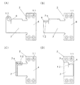
相連結する扉Dと扉枠Fの端面凹部S1,S2に各々固定される一対の旗部材1,2を、一本のピンPで開閉自在に連結する丁番である。
当該例の扉D及び扉枠Fは、各々の表板Df,Ff及び裏板Db,Fbが、扉D及び扉枠Fの側方端面から表裏等量ずつ突出させてあり、当該表裏突出部a,bと端面cとで、旗部材1,2を支持固定するための凹部S1,S2を構成する。
Embodiments of a hidden hinge according to the present invention will be described below in detail with reference to the drawings.
This is a hinge that connects the pair of
In the door D and the door frame F of the example, the front plates Df and Ff and the back plates Db and Fb are projected from the side end surfaces of the door D and the door frame F by the same amount, and the front and back protruding portions. The a and b and the end surface c constitute the recesses S1 and S2 for supporting and fixing the
当該一対の旗部材1,2は、それぞれ凹部S1,S2の最深部たる端面cに固定される定着部3,4と、一対の旗部材1,2を連結する前記ピンPが嵌る軸承部5,6を備え、当該例においては、扉枠Fに固定される旗部材2の定着部4と軸承部6との間に迂回部7を備える。
The pair of
具体的には、扉Dに固定される旗部材(以下、第一旗部材と記す。)1の定着部3及び軸承部5は、曲げ成形が施された一連の板金として連続し(図4参照)、扉枠Fに固定される旗部材(以下、第二旗部材と記す。)2の定着部4、軸承部6、及び迂回部7は、曲げ成形が施された一連の板金として連続する(図3参照)。
Specifically, the
当該例において扉Dに固定される旗部材1の板金は、平板状の定着部3と、当該定着部3の上縁開き方向の端部から上向きに延出する軸承部5を備える(図4(A)参照)。前記軸承部5を定着部3の表方向へ直角に曲げて平伏させ、定着部3には座繰りを施したビス孔8を複数穿設し、軸承部5には一対の旗部材1,2を連結するピンPを螺合するためのネジ孔9を穿設する(図4(B)参照)。
In this example, the sheet metal of the
扉枠Fに固定される旗部材2の板金は、平板状の定着部4の一側辺から直角に屈曲させ、更に直角に定着部4の幅と等しい量だけ反転させる曲げ成形を行うことによって、定着部4に連続したL字状の迂回部7を成形し(図3(C)(D)参照)、当該迂回部7の先端部上位に切り込み10を入れて分割平伏させて軸承部6を成形する(図3(B)参照)。定着部4には座繰りを施したビス孔11を複数穿設し、軸承部6には一対の旗部材1,2を連結するピンPを回転自在に挿通するための軸孔12を穿設する。尚、軸承部6と迂回部7の曲げ成形はいずれを先に行っても良い。
The sheet metal of the
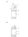
この丁番は、扉D又は扉枠Fの凹部S1,S2の内部で双方のネジ孔9と軸孔12が向き合い、そこへ通されたピンPを開閉軸として扉Dと扉枠Fの相対的な開閉を行わせ、少なくとも閉鎖時においては、一対の旗部材1,2の大部分が扉Dの凹部S1又は扉枠Fの凹部S2に埋没し隠れることとなる。
開閉角度は、前記迂回部7の迂回量と、開閉軸から迂回部7及び定着部4までの最短距離に依存する。
In this hinge, both the screw hole 9 and the
The opening / closing angle depends on the bypassing amount of the
前記迂回部7の定着部4表面からの突出量は、扉Dの凹部S1の深さからその凹部S1に固定される定着部3の厚さを差し引いた量を超える量を基準とする。当該基準の量を採用すれば、当該超えた量が、閉鎖時における扉Dと扉枠Fとの間のクリアランスとなり、当該量を、丁番が容易に見えない最低限のクリアランス(例えば、5mm未満)に設定するだけで、扉Dと扉枠Fとが接触しない良好な開閉を実現できる。
また、当該迂回部7の反転量は、扉Dの凹部S1の深さからその凹部S1に固定される定着部3の厚さを差し引き、更に、定着部3の表面からネジ孔9の中心に至る長さを差し引いた量を超える量が基準とする。当該基準の量を採用すれば、開放限界において、扉Dの表裏いずれかの板Df,Dbと迂回部7との接触が回避できることとなる。
The amount of protrusion of the
The reversal amount of the
上記のとおり迂回部7の形態や寸法を決めれば、扉枠Fの凹部S2は、当該扉枠Fに固定される旗部材2の定着部4の全体が埋没する深さがあれば足り、その深さはより少ないことが望ましい。扉Dの凹部S2の深さは、前記迂回部7の突出長及び反転量から逆算すれば良い。
If the form and dimensions of the
即ち、扉Dの凹部S1の深さは、迂回部7の突出量にその凹部S1に固定される定着部3の厚さを加えた量、又は迂回部7の反転量に、定着部3の表面からネジ孔9の中心に至る長さ及び定着部3の厚みを加えた量の、いずれか少ない量が基準となる。
That is, the depth of the recess S1 of the door D is equal to the amount obtained by adding the thickness of the fixing
当該例では、前記迂回部7における先端部上位の分割起立部7aの側面(分割平伏部分(軸承部6)との分断面)を、扉Dの凹部S1に固定した旗部材1における軸承部5の基部5aの旋回を規制する正転ストッパとし、前記迂回部7における先端部上位の分割起立部7aの先部裏面を、扉Dの凹部S1に固定した旗部材1における軸承部5の先部5bの旋回を規制する逆転ストッパとする。
In this example, the bearing
当該丁番は、前記第一旗部材1を扉Dの凹部S1内における端面cにビス止めし、前記第二旗部材2を、扉枠Fの凹部S2内における端面cに、前記第一旗部材1の固定位置に高さを合わせてビス止めし、前記第二旗部材2の軸承部6の上に、前記第一旗部材1の軸承部5を重ね、上位にある前記第一旗部材1の軸承部5にピンPの基部を螺合し、その結果、当該第一旗部材1の軸承部5の下位に突出した部分が前記第二旗部材2の軸孔12に挿通することによって連結一体となり、扉枠Fに扉Dを開閉自在にガタツキなく支持する。
The hinge secures the
本発明による丁番は、以上の構造を有することから、二つの旗部材1,2とそれを繋ぐ一本のピンPという少ない部材で実現でき、且つ各旗部材1,2は、板金の裁断・穴あけと、曲げ成形という簡単な工程で成形できるにも関わらず、隠し丁番として大きな開閉角度を実現し、扉Dの開閉の際にも、当該丁番の構造のみで、その周辺部材との接触を回避できるという極めて高い実用効果を奏する。
Since the hinge according to the present invention has the above-described structure, it can be realized with a small number of members called two
D 扉,Df 表板(扉),Db 裏板(扉)
F 扉枠,Ff 表板(扉枠),Fb 裏板(扉枠),
a 表突出部,b 裏突出部,c 端面,
S1 凹部(扉),S2 凹部(扉枠),
P ピン,
1 旗部材,2 旗部材(迂回部付き),
3 定着部,4 定着部,
5 軸承部,5a 基部,5b 先部,
6 軸承部,
7 迂回部,7a 分割起立部,
8 ビス孔,9 ネジ孔,10 切り込み,
11 ビス孔,12 軸孔,
D Door, Df Front plate (door), Db Back plate (door)
F door frame, Ff front plate (door frame), Fb back plate (door frame),
a front protrusion, b back protrusion, c end face,
S1 recess (door), S2 recess (door frame),
P pin,
1 flag member, 2 flag member (with detour part),
3 fixing section, 4 fixing section,
5 bearing, 5a base, 5b tip,
6 bearing parts,
7 Detour part, 7a Divided upright part,
8 screw holes, 9 screw holes, 10 notches,
11 screw holes, 12 shaft holes,
Claims (5)
各旗部材は、相連結する扉又は扉枠の端面凹部に各々固定される定着部、及び前記ピンが嵌る軸承部を備え、
一方の旗部材の定着部と軸承部との間に迂回部を備え、
各旗部材の前記定着部及び軸承部、又は前記定着部、軸承部、及び迂回部は、曲げ成形が施された一連の板金として連続し、
前記軸承部又は迂回部に、他方の旗部材における迂回部又は軸承部の一方向への相対的な旋回を規制する正転ストッパ、及び当該他方の旗部材における迂回部又は軸承部の他方向への相対的な旋回を規制する逆転ストッパを備えることを特徴とする丁番。 In the hinge formed by connecting a pair of flag members fixed to the end face recesses of the door or door frame to be connected to each other so as to be opened and closed with one pin,
Each flag member is provided with a fixing part fixed to each end face recess of the door or door frame to be coupled, and a bearing part into which the pin fits,
A detour part is provided between the fixing part of one flag member and the bearing part,
The fixing part and the bearing part of each flag member, or the fixing part, the bearing part, and the detour part are continuous as a series of sheet metal subjected to bending,
A forward rotation stopper for restricting relative turning in one direction of the bypass portion or the bearing portion of the other flag member and the other direction of the bypass portion or the bearing portion of the other flag member in the bearing portion or the bypass portion. A hinge characterized by having a reverse rotation stopper that regulates the relative turning of the.
The hinge according to any one of claims 3 to 4, wherein the forward rotation stopper and the reverse rotation stopper are divided upright portions at the upper end of the tip portion of the bypass portion.
Priority Applications (1)
| Application Number | Priority Date | Filing Date | Title |
|---|---|---|---|
| JP2012184200A JP2014040745A (en) | 2012-08-23 | 2012-08-23 | Hinge |
Applications Claiming Priority (1)
| Application Number | Priority Date | Filing Date | Title |
|---|---|---|---|
| JP2012184200A JP2014040745A (en) | 2012-08-23 | 2012-08-23 | Hinge |
Publications (1)
| Publication Number | Publication Date |
|---|---|
| JP2014040745A true JP2014040745A (en) | 2014-03-06 |
Family
ID=50393189
Family Applications (1)
| Application Number | Title | Priority Date | Filing Date |
|---|---|---|---|
| JP2012184200A Pending JP2014040745A (en) | 2012-08-23 | 2012-08-23 | Hinge |
Country Status (1)
| Country | Link |
|---|---|
| JP (1) | JP2014040745A (en) |
Cited By (1)
| Publication number | Priority date | Publication date | Assignee | Title |
|---|---|---|---|---|
| JP2017017197A (en) * | 2015-07-01 | 2017-01-19 | 河村電器産業株式会社 | Electrical equipment storage box |
Citations (5)
| Publication number | Priority date | Publication date | Assignee | Title |
|---|---|---|---|---|
| JPH064292U (en) * | 1992-04-23 | 1994-01-21 | 近畿工業株式会社 | Framed door |
| JPH07229354A (en) * | 1994-02-21 | 1995-08-29 | Hiroshi Kikko | Hinge provided with function for holding intermediate open degree |
| JPH09137662A (en) * | 1995-09-13 | 1997-05-27 | Sugiura:Kk | Hinge and hinge device |
| JP2005299253A (en) * | 2004-04-13 | 2005-10-27 | Hitoshi Nishitani | Invisible hinge |
| JP2010275698A (en) * | 2009-05-26 | 2010-12-09 | Kawamura Electric Inc | Hinge for box for storing electrical equipment |
-
2012
- 2012-08-23 JP JP2012184200A patent/JP2014040745A/en active Pending
Patent Citations (5)
| Publication number | Priority date | Publication date | Assignee | Title |
|---|---|---|---|---|
| JPH064292U (en) * | 1992-04-23 | 1994-01-21 | 近畿工業株式会社 | Framed door |
| JPH07229354A (en) * | 1994-02-21 | 1995-08-29 | Hiroshi Kikko | Hinge provided with function for holding intermediate open degree |
| JPH09137662A (en) * | 1995-09-13 | 1997-05-27 | Sugiura:Kk | Hinge and hinge device |
| JP2005299253A (en) * | 2004-04-13 | 2005-10-27 | Hitoshi Nishitani | Invisible hinge |
| JP2010275698A (en) * | 2009-05-26 | 2010-12-09 | Kawamura Electric Inc | Hinge for box for storing electrical equipment |
Cited By (1)
| Publication number | Priority date | Publication date | Assignee | Title |
|---|---|---|---|---|
| JP2017017197A (en) * | 2015-07-01 | 2017-01-19 | 河村電器産業株式会社 | Electrical equipment storage box |
Similar Documents
| Publication | Publication Date | Title |
|---|---|---|
| CN108286860A (en) | Refrigerator | |
| CN108302856B (en) | Refrigerator with a door | |
| CN104350226B (en) | Concealed hinge for furniture doors and doors | |
| US20120319422A1 (en) | Console box | |
| US10837210B2 (en) | Hinge and hinge bracket | |
| CN108278841A (en) | Refrigerator | |
| JP5606058B2 (en) | Hidden hinge | |
| JP2013118437A (en) | Folding electronic apparatus | |
| JP2014040745A (en) | Hinge | |
| JP5563228B2 (en) | Door connecting member and door connecting structure using the same | |
| JP2008008015A (en) | Hidden hinge | |
| CN108204180B (en) | Embedded hinge device | |
| JP5401277B2 (en) | Orito | |
| KR20130022366A (en) | A hinge | |
| JP5348690B2 (en) | Slide rotation hinge and portable device | |
| CN202431135U (en) | Gear transmission type folding door | |
| CN109373685B (en) | refrigerator | |
| KR100961232B1 (en) | Hinge assembly | |
| JP5372808B2 (en) | Buried door hinge and door device | |
| JP5401278B2 (en) | Orito | |
| JP6013154B2 (en) | Lattice | |
| TW202024461A (en) | One-touch mounting hinge | |
| JP4699912B2 (en) | Toilet booth door | |
| CN108104636A (en) | Insert hinge device | |
| IT201800003199U1 (en) | CONCEALED HINGE FOR WINDOWS |
Legal Events
| Date | Code | Title | Description |
|---|---|---|---|
| A621 | Written request for application examination |
Free format text: JAPANESE INTERMEDIATE CODE: A621 Effective date: 20140515 |
|
| A977 | Report on retrieval |
Free format text: JAPANESE INTERMEDIATE CODE: A971007 Effective date: 20141008 |
|
| A131 | Notification of reasons for refusal |
Free format text: JAPANESE INTERMEDIATE CODE: A131 Effective date: 20141104 |
|
| A02 | Decision of refusal |
Free format text: JAPANESE INTERMEDIATE CODE: A02 Effective date: 20150303 |