JP6220575B2 - Sample processing apparatus and abnormality detection method for sample processing apparatus - Google Patents
Sample processing apparatus and abnormality detection method for sample processing apparatus Download PDFInfo
- Publication number
- JP6220575B2 JP6220575B2 JP2013135426A JP2013135426A JP6220575B2 JP 6220575 B2 JP6220575 B2 JP 6220575B2 JP 2013135426 A JP2013135426 A JP 2013135426A JP 2013135426 A JP2013135426 A JP 2013135426A JP 6220575 B2 JP6220575 B2 JP 6220575B2
- Authority
- JP
- Japan
- Prior art keywords
- sample
- suction
- liquid
- processing apparatus
- sample processing
- Prior art date
- Legal status (The legal status is an assumption and is not a legal conclusion. Google has not performed a legal analysis and makes no representation as to the accuracy of the status listed.)
- Active
Links
Images


Classifications
-
- G—PHYSICS
- G01—MEASURING; TESTING
- G01N—INVESTIGATING OR ANALYSING MATERIALS BY DETERMINING THEIR CHEMICAL OR PHYSICAL PROPERTIES
- G01N35/00—Automatic analysis not limited to methods or materials provided for in any single one of groups G01N1/00 - G01N33/00; Handling materials therefor
- G01N35/10—Devices for transferring samples or any liquids to, in, or from, the analysis apparatus, e.g. suction devices, injection devices
- G01N35/1009—Characterised by arrangements for controlling the aspiration or dispense of liquids
Landscapes
- Life Sciences & Earth Sciences (AREA)
- General Physics & Mathematics (AREA)
- Physics & Mathematics (AREA)
- Immunology (AREA)
- Analytical Chemistry (AREA)
- Biochemistry (AREA)
- General Health & Medical Sciences (AREA)
- Chemical & Material Sciences (AREA)
- Health & Medical Sciences (AREA)
- Pathology (AREA)
- Automatic Analysis And Handling Materials Therefor (AREA)
- Engineering & Computer Science (AREA)
- Environmental & Geological Engineering (AREA)
- Geology (AREA)
- Remote Sensing (AREA)
- General Life Sciences & Earth Sciences (AREA)
- Geophysics (AREA)
- Hydrology & Water Resources (AREA)
Description
本発明は、容器に収容された試料を吸引して処理する試料処理装置および当該試料処理装置の異常検出方法に関する。 The present invention relates to a sample processing apparatus that sucks and processes a sample contained in a container, and an abnormality detection method for the sample processing apparatus.
血液や尿などの試料に対して測定、分析などの処理を行う試料処理装置には、容器から試料を吸引するための吸引部が備えられている。吸引部の一端から吸引された試料のうち、所定量の試料が希釈液や薬剤などの試薬と混合されて処理される。その後、吸引部は、洗浄液により洗浄される。 2. Description of the Related Art A sample processing apparatus that performs processing such as measurement and analysis on a sample such as blood or urine includes a suction unit for sucking the sample from a container. Of the sample sucked from one end of the suction unit, a predetermined amount of the sample is mixed with a reagent such as a diluent or a medicine for processing. Thereafter, the suction part is cleaned with the cleaning liquid.
吸引された試料から所定量の試料を定量採取する方法として、たとえば、吸引部の一端から所定量の試料を吸引しチャンバ内に吐出分注するタイプ(たとえば、特許文献1参照)と、吸引部に設けられたサンプリングバルブによって試料を定量採取し、試薬とともにチャンバに押し流すタイプ(たとえば、特許文献2参照)とがある。 As a method for quantitatively collecting a predetermined amount of sample from the sucked sample, for example, a type in which a predetermined amount of sample is sucked from one end of the suction unit and dispensed into the chamber (for example, see Patent Document 1), and a suction unit There is a type (for example, refer to Patent Document 2) in which a sample is sampled quantitatively by a sampling valve provided in and is pushed into a chamber together with a reagent.
このような方法により試料を採取する場合、吸引部により試料が適切に吸引されないと、処理結果に悪影響が生じる惧れがある。かかる不具合を防ぐため、吸引部にセンサを設けて吸引部による試料の吸引状態を監視することが行われている。たとえば、特許文献3に記載の装置では、試料保持流路の中途部に光学検知装置が配置され、当該光学検知装置によって試料保持流路に吸引された空気層の長さを検出することにより、試料針の詰まりが検知される。 When a sample is collected by such a method, the processing result may be adversely affected unless the sample is appropriately sucked by the suction unit. In order to prevent such a problem, a sensor is provided in the suction part to monitor the suction state of the sample by the suction part. For example, in the apparatus described in Patent Document 3, an optical detection device is arranged in the middle of the sample holding channel, and by detecting the length of the air layer sucked into the sample holding channel by the optical detection device, Sample needle clogging is detected.
上記特許文献3の方法は、特に、試料針の詰まりによる吸引動作の異常を検出するためのものであるため、吸引動作におけるその他の異常の検出には、対応できないものであった。 The method of Patent Document 3 described above is particularly for detecting an abnormality in the suction operation due to the clogging of the sample needle, and therefore cannot cope with detection of other abnormalities in the suction operation.
かかる課題に鑑み、本発明は、吸引動作における異常を、より幅広く検出することが可能な試料処理装置および異常検出方法を提供することを目的とする。 In view of such a problem, an object of the present invention is to provide a sample processing apparatus and an abnormality detection method capable of detecting an abnormality in a suction operation more widely.
本発明の第1の態様は、容器に収容された試料を吸引して処理を行う試料処理装置に関する。この態様に係る試料処理装置は、一端側にポンプを有し、他端側に吸引ピペットを有し、前記吸引ピペットの吸引口から容器に収容された試料を吸引可能な吸引部と、前記容器に収容された試料の内部および外部に前記吸引ピペットを移動させる昇降部と、前記吸引部の所定位置における液体の有無を検知可能なセンサ部と、制御部と、を備える。そして、前記制御部は、前記吸引部により容器から試料を吸引するための第1吸引動作と、前記第1吸引動作を行った後に前記吸引ピペットを上昇させて前記吸引口を試料外の位置に位置付け、前記吸引部により試料外の空気を吸引するための第2吸引動作とを行い、前記第1吸引動作を行った際の前記センサ部による液体有無の第1検知結果と、前記第2吸引動作を行った際の前記センサ部による液体有無の第2検知結果との組み合わせに対応する試料吸引動作の異常を検出する。 A first aspect of the present invention relates to a sample processing apparatus that performs processing by sucking a sample contained in a container. The sample processing apparatus according to this aspect includes a pump on one end side , a suction pipette on the other end side , a suction unit capable of sucking a sample contained in the container from the suction port of the suction pipette, and the container An elevating unit that moves the suction pipette inside and outside the sample housed in the sensor, a sensor unit that can detect the presence or absence of liquid at a predetermined position of the suction unit, and a control unit . Then, the control unit performs a first suction operation for sucking the sample from the container by the suction unit, and raises the suction pipette after performing the first suction operation so that the suction port is positioned outside the sample. Positioning, performing a second aspiration operation for aspirating air outside the sample by the aspiration unit , a first detection result of the presence or absence of liquid by the sensor unit when the first aspiration operation is performed, and the second aspiration Abnormality of the sample suction operation corresponding to the combination with the second detection result of the presence or absence of liquid by the sensor unit when the operation is performed is detected .
本態様に係る試料処理装置によれば、第1吸引動作を行った際のセンサ部による第1検知結果と、第2吸引動作を行った際のセンサ部による第2検知結果との組合せに基づいて、試料吸引動作における異常の検出が行われるため、吸引動作における種々の異常を幅広く検出することができる。 According to the sample processing apparatus according to this aspect, based on a combination of the first detection result by the sensor unit when the first suction operation is performed and the second detection result by the sensor unit when the second suction operation is performed. Thus, since abnormality in the sample aspirating operation is detected, various abnormalities in the aspirating operation can be widely detected.
本態様に係る試料処理装置において、前記制御部は、前記第1検知結果と前記第2検知結果との組み合わせが、試料吸引動作における各種の異常を示す組み合わせの条件群の何れかに合致した場合に、合致した組み合わせの条件に対応する試料吸引動作の異常を検出するよう構成され得る。 In the sample processing apparatus according to this aspect, the control unit, when the combination of the first detection result and the second detection result matches any of a combination of condition groups indicating various abnormalities in the sample suction operation In addition, it may be configured to detect an abnormality in the sample aspirating operation corresponding to the matched combination condition.
この構成において、前記センサ部は、前記吸引ピペットに設けられ得る。 In this configuration, the sensor unit may be provided in the suction pipette.
あるいは、前記吸引部が、前記吸引ピペットと前記ポンプとを接続する吸引ラインを有する場合、前記センサ部は、前記吸引ラインに設けられ得る。 Or when the said suction part has the suction line which connects the said suction pipette and the said pump, the said sensor part may be provided in the said suction line.
また、本態様に係る試料処理装置において、前記制御部は、たとえば、前記第1吸引動作の際に前記センサ部により前記所定位置に液体が無いことが検知され、且つ、前記第2吸引動作の際に前記センサ部により前記所定位置に液体が無いことが検知された場合に、前記異常として、吸引可能な量の試料が前記容器に収容されていないことを検出するよう構成され得る。こうすると、第1検知結果と第2検知結果の組合せに基づいて、吸引可能な量の試料が容器に収容されておらず、吸引動作を適正に行えなかったことが検出可能となる。より詳細には、第1吸引動作においては、試料を吸引するための動作がなされるため、通常であれば、第1検知結果として、所定位置に液体が有るとの検知結果が得られるべきである。しかし、ここでは、第1検知結果として、液体がないとの検知結果が得られているため、第1吸引動作において、試料ではなく空気が吸引されたと判断され、この判断に基づき、容器が空である等、吸引可能な量の試料が前記容器に収容されていないことが検出される。 Further, in the sample processing apparatus according to the present embodiment, the control unit, for example, the possible liquid is not is detected in the predetermined position by the sensor unit to the first time of suction operation, and, of the second suction operation When the sensor unit detects that there is no liquid at the predetermined position, it may be configured to detect that the sample that can be sucked is not stored in the container as the abnormality. If it carries out like this, based on the combination of the 1st detection result and the 2nd detection result, it will become possible to detect that the sample of the amount which can be sucked is not stored in the container, and the suction operation could not be performed properly. More specifically, since the operation for aspirating the sample is performed in the first aspiration operation, a detection result indicating that liquid is present at a predetermined position should be obtained as the first detection result. is there. However, here, since the detection result that there is no liquid is obtained as the first detection result, it is determined in the first suction operation that air is sucked instead of the sample, and based on this determination, the container is empty. For example, it is detected that an amount of a sample that can be aspirated is not contained in the container.
また、本態様に係る試料処理装置において、前記制御部は、たとえば、前記第1吸引動作の際に前記センサ部により前記所定位置に液体が有ることが検知され、且つ、前記第2吸引動作の際に前記センサ部により前記所定位置に液体が有ることが検知された場合、前記異常として、前記吸引部における試料の流れの不具合を検出するよう構成され得る。こうすると、第1検知結果と第2検知結果の組合せに基づいて、吸引部の詰まりや、吸引部に生じたその他の障害によって、吸引部における試料の流れに不具合が生じたことが検出可能となる。より詳細には、第2吸引動作においては、空気を吸引するための動作がなされるため、通常であれば、第2検知結果として、所定位置に液体が無い(空気がある)との検知結果が得られるべきである。しかし、ここでは、第2検知結果として、液体があるとの検知結果が得られているため、第2吸引動作において、試料の吸引が滞り所定位置に空気が到達しなかったと判断され、この判断に基づき、吸引部における試料の流れに不具合が生じたことが検出される。 Further, in the sample processing apparatus according to the present embodiment, the control unit, for example, the liquid that is present is detected in the predetermined position by the sensor unit during the first suction operation, and, of the second suction operation When the sensor unit detects that the liquid is present at the predetermined position, the abnormality may be detected as the abnormality of the sample flow in the suction unit. In this way, based on the combination of the first detection result and the second detection result, it is possible to detect that a defect has occurred in the sample flow in the suction part due to clogging of the suction part or other troubles occurring in the suction part. Become. More specifically, since the operation for sucking air is performed in the second suction operation, the detection result that there is no liquid (there is air) as a second detection result is usually used. Should be obtained. However, since the detection result that there is a liquid is obtained as the second detection result, it is determined that the sample has been aspirated and the air has not reached the predetermined position in the second suction operation. Based on the above, it is detected that a problem has occurred in the flow of the sample in the suction part.
たとえば、本態様に係る試料処理装置が、前記吸引部内に、前記試料中から異物を除去するためのフィルタを備えるような場合には、フィルタの詰まりによって、第2吸引動作の際に、試料の流れが滞ることが起こり得る。本態様に係る試料処理装置によれば、このような場合にも、第1検知結果と第2検知結果との組合せに基づいて、フィルタの詰まりによる試料の流れの不具合を検出することができる。 For example, in the case where the sample processing apparatus according to this aspect includes a filter for removing foreign substances from the sample in the suction unit, the sample is removed during the second suction operation due to clogging of the filter. It is possible for the flow to stagnate. According to the sample processing apparatus according to this aspect, in such a case as well, it is possible to detect a malfunction in the sample flow due to clogging of the filter based on the combination of the first detection result and the second detection result.
本態様に係る試料処理装置において、前記制御部は、前記第1吸引動作と前記第2吸引動作との間に、さらに、空気を吸引する第3吸引動作を行い、前記第3吸引動作を行った際の前記センサ部による液体有無の第3検知結果と、前記第1検知結果および前記第2検知結果との組み合わせに対応する試料吸引動作の異常を検出するよう構成され得る。このように、第3検知結果を補足的に用いることにより、第1検知結果と第2検知結果からは適正に判別され得なかった異常を適正に判別することが可能となる。 In the sample processing apparatus according to this embodiment, the control unit, between the second suction operation and the first suction operation, further, subjected to a third suction operation for sucking the air, subjected to the third suction operation a third detection result of fluid presence by the sensor portion when the may be configured to detect the abnormality of the sample suction operation corresponding to a combination of the first detection result and the second detection result. As described above, by supplementarily using the third detection result, it is possible to appropriately determine an abnormality that could not be properly determined from the first detection result and the second detection result.
また、本態様に係る試料処理装置において、前記制御部は、前記第2吸引動作の後、試料の処理動作へと移行する前に、吸引した試料を前記吸引部において逆流させる動作をさらに行うよう構成され得る。こうすると、試料の逆流により、たとえばフィルタの目詰まり等を解消することができ、次回の吸引動作を適正に行うことができる。 Further, in the sample processing apparatus according to the present embodiment, the control unit, after the second suction operation, before moving to the specimen processing operation, so as to further perform an operation of the aspirated sample to flow back in the suction unit Can be configured. In this case, for example, clogging of the filter can be eliminated by the backflow of the sample, and the next suction operation can be appropriately performed.
また、本態様に係る試料処理装置において、前記制御部は、前記異常が検出されたことを操作者に通知するための異常通知動作をさらに行うよう構成され得る。こうすると、操作者は、試料の吸引動作に異常が生じたことを容易に知ることができ、円滑に、適切な対応を採ることができる。 Further, in the sample processing apparatus according to the present embodiment, the control unit, the abnormality may be configured to further perform the abnormality notification operation for notifying the operator that has been detected. In this way, the operator can easily know that an abnormality has occurred in the suction operation of the sample, and can take appropriate measures smoothly.
また、本態様に係る試料処理装置において、前記制御部は、前記異常が検出された場合に、前記異常を解消するための復帰動作を行うよう構成され得る。こうすると、異常発生後の処理動作が円滑に進められ得る。 Further, in the sample processing apparatus according to the present embodiment, the control unit, when the abnormality is detected, may be configured to perform the return operation for eliminating the abnormal. In this way, the processing operation after the occurrence of an abnormality can proceed smoothly.
本発明の第2の態様は、容器に収容された試料を処理する試料処理装置の異常検出方法に関する。本態様に係る異常検出方法は、液体を検知可能なセンサ部を備えた吸引部により前記容器から試料を吸引するための動作を行う第1吸引工程と、前記第1吸引工程の後、前記吸引部により試料外の空気を吸引するための動作を行う第2吸引工程と、前記第1吸引工程における前記センサ部による液体有無の第1検知結果と前記第2吸引工程における前記センサ部による液体有無の第2検知結果との組み合わせに対応する試料吸引動作の異常を検出する異常検出工程と、を含む。 A 2nd aspect of this invention is related with the abnormality detection method of the sample processing apparatus which processes the sample accommodated in the container. The abnormality detection method according to this aspect includes a first suction step of performing an operation for sucking a sample from the container by a suction unit including a sensor unit capable of detecting a liquid, and the suction after the first suction step. A second suction step for performing an operation for sucking air outside the sample by the unit, a first detection result of the presence or absence of liquid by the sensor unit in the first suction step, and the presence or absence of liquid by the sensor unit in the second suction step And an abnormality detection step of detecting an abnormality in the sample suction operation corresponding to the combination with the second detection result.
本態様に係る異常検出方法によれば、上記第1の態様と同様、第1吸引動作を行った際のセンサ部による第1検知結果と、第2吸引動作を行った際のセンサ部による第2検知結果との組合せに基づいて、試料吸引動作における異常の検出が行われるため、吸引動作における種々の異常を幅広く検出することができる。 According to the abnormality detection method according to this aspect, similarly to the first aspect, the first detection result by the sensor unit when the first suction operation is performed and the first detection result by the sensor unit when the second suction operation is performed. Since the abnormality in the sample aspirating operation is detected based on the combination with the two detection results, various abnormalities in the aspirating operation can be widely detected.
以上のとおり、本発明によれば、吸引動作における異常を、より幅広く検出することが可能な試料処理装置および異常検出方法を提供することができる。 As described above, according to the present invention, it is possible to provide a sample processing apparatus and an abnormality detection method capable of detecting an abnormality in the suction operation more widely.
本発明の効果ないし意義は、以下に示す実施の形態の説明により更に明らかとなろう。ただし、以下に示す実施の形態は、あくまでも、本発明を実施化する際の一つの例示であって、本発明は、以下の実施の形態により何ら制限されるものではない。 The effects and significance of the present invention will become more apparent from the following description of embodiments. However, the embodiment described below is merely an example when the present invention is implemented, and the present invention is not limited to the following embodiment.
本実施の形態は、尿検体について複数段階の吸引動作を行い、かかる吸引動作の結果から得られる吸引部の異常を検出する尿検体分析装置に本発明を適用したものである。 In the present embodiment, the present invention is applied to a urine sample analyzer that performs a plurality of steps of suction operation on a urine sample and detects an abnormality of the suction unit obtained from the result of the suction operation.
以下、本実施の形態に係る尿検体分析装置について、図面を参照して説明する。 Hereinafter, the urine sample analyzer according to the present embodiment will be described with reference to the drawings.
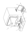
図1は、本実施の形態に係る尿検体分析装置1の構成を示す図である。
FIG. 1 is a diagram showing a configuration of a
尿検体分析装置1は、測定装置2と、搬送装置3と、情報処理装置4を備える。測定装置2は、尿検体に含まれている細菌、および白血球等の尿中有形成分をフローサイトメーターにより光学的に測定する。搬送装置3は、検体容器Tが測定装置2に供給されるよう、検体ラックLを搬送する。情報処理装置4は、測定装置2による測定結果を分析し、分析結果を表示部420に表示する。
The
図2は、測定装置2の要部構成を示すブロック図である。
FIG. 2 is a block diagram showing the main configuration of the measuring
測定装置2は、検体分配部201と、試料調製部202と、光学検出部203と、信号処理回路210と、CPU204と、通信インターフェース205と、メモリ206とを有する。信号処理回路210は、アナログ信号処理回路211と、A/Dコンバータ212と、デジタル信号処理回路213と、メモリ214とを有する。
The measuring
検体分配部201は、吸引ピペットとポンプ等を備えている。また、検体分配部201は、吸引ピペットを駆動させるための所定の駆動機構を備えている。検体分配部201は、吸引ピペットを下降させた状態でポンプを駆動することにより、搬送装置3により供給された検体容器Tから所定量の試料液を吸引する。また、検体分配部201は、試料を吸引した後、吸引ピペットを上昇させた状態でポンプを駆動することにより、空気を吸引する。
The
本実施の形態では、このように試料液の吸引動作と空気の吸引動作を組み合わせることによって、吸引動作の異常の有無が判定される。吸引動作に異常がないと判定されると、検体分配部201は、吸引ピペット内に吸引された試料を試料調製部202に供給する。なお、試料の吸引動作と、吸引動作の異常の有無の判定処理については、追って、図5(a)ないし図8(c)を参照して説明する。
In the present embodiment, the presence or absence of an abnormality in the suction operation is determined by combining the sample liquid suction operation and the air suction operation in this manner. If it is determined that there is no abnormality in the suction operation, the
試料調製部202は、試薬容器と、混合容器と、ポンプ等を備えている。混合容器では
、検体分配部201から供給された試料に対して、試薬容器から供給される希釈液と染色液が混合され、測定試料の調製が行われる。混合容器で調製された測定試料は、ポンプにより、シース液と共に光学検出部203のシースフローセル203a(図3参照)に供給される。
The
光学検出部203は、測定試料に対してレーザ光を照射し、これにより生じた前方散乱光と、側方蛍光と、側方散乱光に基づく電気信号を、アナログ信号処理回路211に出力する。光学検出部203は、シースフローセル203aを流れる測定試料にレーザ光を照射する照射光学系と、測定試料から生じた前方散乱光、側方蛍光および側方散乱光をそれぞれ受光する受光光学系を備えている。かかる光学系の構成は、従来周知であるので、ここではその説明を省略する。
The
アナログ信号処理回路211は、CPU204の指示に従って、光学検出部203から出力された電気信号を増幅し、A/Dコンバータ212に出力する。A/Dコンバータ212は、アナログ信号処理回路211によって増幅された電気信号をデジタル信号に変換し、デジタル信号処理回路213に出力する。デジタル信号処理回路213は、CPU204の指示に従って、A/Dコンバータ212から出力されるデジタル信号に対して所定の信号処理を施す。信号処理が施されたデジタル信号はメモリ214に記憶される。
The analog
CPU204は、通信インターフェース205を介して情報処理装置4から制御信号を受信し、かかる制御信号に従って測定装置2の各部を制御する。また、CPU204は、メモリ214に記憶されたデジタル信号から、前方散乱光および側方蛍光に基づく測定データを生成し、かかる測定データを通信インターフェース205に出力する。さらに、CPU204は、後述する液体検知部201d(図3参照)による検知結果を、通信インターフェース205を介して、情報処理装置4に送信する。
The
通信インターフェース205は、CPU204から出力される測定データを情報処理装置4に送信し、情報処理装置4から出力される制御信号を受信する。メモリ206は、CPU204の作業領域として用いられる。
The
図3は、検体分配部201および試料調製部202の構成を示す概要図である。なお、図3では、検体分配部201および試料調製部202のうち、吸引ピペット201aから反応槽202cまでの流路、駆動機構等が示されており、その他の流路および駆動機構等は図示省略されている。
FIG. 3 is a schematic diagram illustrating the configuration of the
図3を参照して、検体分配部201は、吸引ピペット201aと、昇降機構部201bと、サンプルフィルタ201cと、液体検知部201dと、シリンジポンプ201eと、洗浄液容器201fと、洗浄槽201gと、サンプリングバルブ201hとを備える。試料調製部202は、ダイヤフラムポンプ202aと、希釈液容器202bと、反応槽202cとを備える。吸引ピペット201aとシリンジポンプ201eは、樹脂製のチューブである吸引ラインにより接続されている。吸引ピペット201a、シリンジポンプ201e、および吸引ラインを含み、検体容器Tに収容された試料液(尿)の吸引を行う機構を「吸引部」と称する。また、吸引口Pa側を吸引部の上流側、シリンジポンプ201e側を吸引部の下流側と称する。
Referring to FIG. 3, the
試料吸引動作において、吸引ピペット201aは、昇降機構部201bにより下降され、検体容器T内に挿入される。これにより、吸引ピペット201aの端部に設けられた吸引口Paが、検体容器Tに収容された試料液に浸される。この状態で、吸引ピペット201aに対し、シリンジポンプ201eにより負圧が与えられる。これにより、試料液が吸引される。吸引された試料は、吸引ピペット201a内を通り、サンプルフィルタ201
cおよび液体検知部201dを介して、サンプリングバルブ201hに送出される。その後、吸引ピペット201aは、昇降機構部201bにより上昇され、検体容器Tに収容された試料液の液面から吸引口Paが離される。この状態で、シリンジポンプ201eにより吸引ピペット201aに負圧が与えられ、吸引ピペット201aにより、空気が吸引される。
In the sample aspirating operation, the
c and the
サンプルフィルタ201cは、複数の小さな孔を有し、吸引された試料液中の不要物を除去する。
The
液体検知部201dは、2つの電極と、これらの電極間にかかる電圧の変化を検出する検出回路部からなる。液体検知部201dは、吸引ピペット201aとシリンジポンプ201eを接続する吸引ラインに設けられている。電極間に電解質の試料液が通流すると、電極間の試料液に電流が流れ、電極間の電圧が変化する。液体検知部201dの検出回路部は、電圧の変化量が所定の閾値を超えた場合、検出信号を測定装置2のCPU204に出力する。すなわち、電極間に試料液が存在すると、試料液が有ることを示す検出信号が、液体検知部201dからCPU204に出力される。
The
サンプリングバルブ201hは、切換アームを動作させることにより、吸引した試料を定量する。定量された試料は、ダイヤフラムポンプ202aにより、希釈液容器202bから導かれた希釈液とともに、反応槽202cへ分注される。また、反応槽202cには、染色液容器から染色液が分注され、染色液に含まれる色素により染色が施される。
The
このようにして調製された試料は、光学検出部203に導かれ、シースフローセル203aにおいてシース液に包まれた細い流れを形成し、そこに、レーザ光が照射される。このような動作は、情報処理装置4の制御により、図示しない駆動部や電磁弁等を動作させることにより、自動的に行われる。
The sample prepared in this way is guided to the
こうして、試料の測定が完了すると、流路の洗浄動作が行われる。まず、吸引ピペット201aが所定の駆動機構(図示せず)により洗浄槽201gに移動される。また、サンプリングバルブ201hの切換アームが、吸引ピペット201aとシリンジポンプ201eとの間に流路が形成される位置に切り換えられる。その後、シリンジポンプ201eから流路に陽圧が与えられ、さらに、洗浄液容器201fの電磁弁が開けられる。これにより、洗浄液容器201f内の洗浄液が、シリンジポンプ201e、サンプリングバルブ201hおよび吸引ピペット201aを通過して洗浄槽201g内に排出される。こうして、試料吸引にかかる流路の洗浄が行われる。また、洗浄槽201gに吸引ピペット201aから洗浄液が吐出されることにより、吸引ピペット201aの外周が洗浄される。なお、反応槽202c等他の流路機構についても、図示しない所定の洗浄機構により洗浄が行われる。
Thus, when the measurement of the sample is completed, the flow path cleaning operation is performed. First, the
吸引ピペット201aの洗浄が完了すると、吸引ピペット201aは、次の測定にかかる試料液を吸引できるように元の位置に戻される。そして、吸引ピペット201aが上昇された状態で、シリンジポンプ201eから吸引ピペット201aに負圧が与えられ、吸引ピペット201aから少量の空気が吸引される。これにより、吸引ピペット201a内に満たされた洗浄液と次の測定時に吸引する試料液との間に空気層が生じ、洗浄液と試料液とが混ざり合うことが抑制される。なお、本実施の形態では、次の試料液の吸引速度が略一定になるように、空気層が極力小さくなるように空気の吸引量が調整されている。
When the cleaning of the
図4は、情報処理装置4の構成を示す図である。 FIG. 4 is a diagram illustrating a configuration of the information processing apparatus 4.
情報処理装置4は、パーソナルコンピュータからなっており、本体400と、入力部4
10と、表示部420(図1参照)から構成されている。本体400は、CPU401と、ROM402と、RAM403と、ハードディスク404と、読出装置405と、入出力インターフェース406と、画像出力インターフェース407と、通信インターフェース408とを有する。
The information processing apparatus 4 includes a personal computer, and includes a
10 and a display unit 420 (see FIG. 1). The
CPU401は、ROM402に記憶されているコンピュータプログラムおよびRAM403にロードされたコンピュータプログラムを実行する。RAM403は、ROM402およびハードディスク404に記録されているコンピュータプログラムの読み出しに用いられる。また、RAM403は、これらのコンピュータプログラムを実行するときに、CPU401の作業領域としても利用される。
The
ハードディスク404には、オペレーティングシステムおよびアプリケーションプログラムなど、CPU401に実行させるための種々のコンピュータプログラムおよびコンピュータプログラムの実行に用いるデータがインストールされている。また、ハードディスク404には、測定装置2から受信した測定データが記憶されている。
The
さらに、ハードディスク404には、測定データに基づいて検体の分析を行うためのプログラムや、分析結果を表示部420上に表示を行う表示プログラムがインストールされている。これらプログラムがインストールされることで、分析処理や表示処理が行われる。すなわち、CPU401は、かかるプログラムにより、後述する図7の処理を実行する機能や、図8(a)〜図8(c)の画面を表示する機能が付与されている。
Further, the
読出装置405は、CDドライブまたはDVDドライブ等によって構成されており、記録媒体などの外部記憶に記録されたコンピュータプログラムおよびデータを読み出すことができる。これにより、情報処理装置4で実行されるプログラムは、記録媒体などの外部記憶を介して更新可能となっている。
The
入出力インターフェース406には、マウスやキーボードからなる入力部410が接続されており、ユーザが入力部410を使用することにより、情報処理装置4に対する指示が行われる。画像出力インターフェース407は、ディスプレイ等で構成された表示部420に接続されており、画像データに応じた映像信号を、表示部420に出力する。表示部420は、入力された映像信号をもとに、画像を表示する。
An
また、通信インターフェース408により、測定装置2から送信された測定データの受信が可能となる。かかる測定データは、ハードディスク404に記憶される。
The
ここで、本実施の形態の尿検体分析装置1における試料吸引動作と吸引動作の異常判定処理について説明する。
Here, the sample suction operation and the abnormality determination process of the suction operation in the
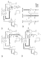
図5(a)〜図5(c)は、試料液の正常な吸引動作を模式的に示す図である。図5(d)は、試料液の正常な吸引動作時における液体検知部201d周辺の流路の状況を模式的に示す図である。なお、便宜上、図5(a)〜図5(c)には、試料液吸引にかかる流路のみが示されている。また、図5(d)では、吸引ピペット201aの端部が流路の端部となるが、便宜上、吸引ピペット201aの図示は省略されている。
Fig.5 (a)-FIG.5 (c) are figures which show the normal suction operation | movement of a sample liquid typically. FIG. 5D is a diagram schematically illustrating the state of the flow path around the
試料を吸引する前の状態では、図5(d)の左端の図に示すように、液体検知部201dからサンプルフィルタ201cまでの流路に、前回の測定処理における洗浄動作によって洗浄液が満たされている。また、流路の端部には、空気層が設けられている。なお、図中の「△」は、試料液の両端を示している。
In the state before the sample is sucked, as shown in the leftmost diagram of FIG. 5D, the flow from the
図5(a)を参照して、試料吸引時には、まず、吸引ピペット201aが下降され、検体容器Tに収容された試料液に吸引ピペット201aの吸引口Paが浸けられる。この状態で、シリンジポンプ201eにより負圧が与えられ、試料液が吸引される。これにより、試料液は、サンプルフィルタ201cを通り、吸引部の下流側に送出される。1回目の吸引動作では、試料液の前端が液体検知部201dの電極の位置を超える位置に試料液が位置付けられる。これにより、図5(d)の中央の図に示す状態となる。この状態では、液体検知部201dの電極間に試料液が介在するため、液体検知部201dにより、試料液が検知される。
Referring to FIG. 5A, at the time of sample suction, first, the
次に、図5(b)に示すように、吸引ピペット201aが上昇され、吸引ピペット201aの吸引口Paが検体容器Tに収容された試料液の液面から離される。この状態で、シリンジポンプ201eにより負圧が与えられ、空気が吸引される。これにより、1回目の吸引動作によって吸引された試料液が吸引部の下流側に送出される。2回目の吸引動作では、試料液の後端が液体検知部201dの電極を超える位置に位置付けられる。こうして、図5(d)の右端の図に示す状態となる。この状態では、液体検知部201dの電極間に空気が介在するため、液体検知部201dにより、試料液は検知されない。
Next, as shown in FIG. 5B, the
その後、図5(c)に示すように、サンプリングバルブ201hが操作され、定量された試料が反応槽202cに分注される。
Thereafter, as shown in FIG. 5C, the
本実施の形態では、吸引動作が正常になされると、1回目の吸引動作において、液体検知部201dにより試料液が検知され、2回目の吸引動作において、液体検知部201dにより試料液が検知されないように、試料液、空気の吸引量および流路の長さ等が調整されている。このように構成されることにより、これら2回の吸引動作における試料液の有無の検知結果に基づいて、後述のように、吸引動作に異常があるか否かを判定することができる。
In the present embodiment, when the suction operation is performed normally, the sample liquid is detected by the
また、本実施の形態では、2回目の吸引動作において空気が吸引されるため、検体容器Tから吸引される試料液の量を抑えることができる。たとえば、1回の試料液の吸引動作のみで試料液をサンプリングバルブ201hに到達させる場合には、サンプリングバルブ201hまでの吸引ラインの長さに応じた量の試料液を吸引する必要がある。これに対し、本実施の形態では、2回目に空気が吸引されるため、試料液の吸引量が少なくても、試料液をサンプリングバルブ201hに供給することができる。これにより、無駄な試料液の吸引を抑えることができる。また、このように、試料液の吸引量を減らすことができるため、サンプルフィルタ201cを通過する試料液の量を抑えることができ、その結果、サンプルフィルタ201cにおける詰まりの発生を抑えることができるとの効果も奏され得る。
In the present embodiment, since the air is sucked in the second suction operation, the amount of the sample liquid sucked from the sample container T can be suppressed. For example, when the sample liquid reaches the
次に、吸引動作に異常があった場合の具体例について説明する。 Next, a specific example when there is an abnormality in the suction operation will be described.
図6(a)〜図6(c)は、試料液の異常な吸引動作時における液体検知部201d周辺の流路の状況を模式的に示す図である。図6(d)は、試料液の吸引動作の判定方法の例を示す図である。図6(d)では、液体検知部201dにより試料液が検知されたことが“○”で示され、液体検知部201dにより試料液が検知されなかったことが“×”で示されている。
FIG. 6A to FIG. 6C are diagrams schematically illustrating the state of the flow path around the
たとえば、尿路感染症に罹患した患者から採取された尿が架設されたような場合、試料液中には、夾雑物が多く含まれ、また、白血球が凝集して大型の粒子成分が含まれる。この場合、これらの夾雑物や粒子成分がサンプルフィルタ201cに補足され、その結果、サンプルフィルタ201cに詰まりが発生する。このため、試料吸引開始時には比較的良
好に試料液が吸引されるが、徐々に、吸引速度が低下し、吸引部における試料の流れが滞ることが起こり得る。
For example, when urine collected from a patient suffering from a urinary tract infection is erected, the sample solution contains a large amount of contaminants, and leukocytes aggregate to contain large particle components. . In this case, these contaminants and particle components are captured by the
このような場合、図6(a)に示すように、1回目の吸引動作(試料の吸引)において、液体検知部201dにより試料液が検知され、その後、2回目の吸引動作(空気の吸引)においても、液体検知部201dにより試料液が検知される。ここでは、2回目の吸引動作において、サンプルフィルタ201cの詰まりにより試料の吸引が滞り、液体検知部201dの電極の位置まで空気が到達していない。本実施の形態では、このように、1回目、2回目の吸引動作ともに、試料液が検知されると、図6(d)に示すように、サンプルフィルタ201cに詰まりが発生したと判定される。
In such a case, as shown in FIG. 6A, in the first suction operation (sample suction), the sample liquid is detected by the
また、たとえば、検体容器Tに試料が収容されずに試料吸引動作が開始された場合、吸引ピペット201aが下降された状態であっても試料液は吸引されず、空気のみが吸引される。
Further, for example, when the sample suction operation is started without storing the sample in the sample container T, the sample liquid is not sucked and only the air is sucked even when the
このような場合、図6(b)に示すように、1回目、2回目の吸引動作ともに、液体検知部201dにより、試料液が検知され得ない。本実施の形態では、このように、1回目、2回目の吸引動作ともに、試料液が検知されないと、図6(d)に示すように、検体容器Tに試料液が収容されていないと判定される。
In such a case, as shown in FIG. 6B, the sample liquid cannot be detected by the
なお、検体容器Tに試料液が全く存在しない場合の他、試料液が僅かに存在するが、吸引ピペット201aで吸引可能な量に満たない場合であっても、液体検知部201dにより、検体容器Tに試料が収容されていない場合と同様の検知がなされる。したがって、この場合も、検体容器Tに試料液が収容されていないと判定される。
In addition to the case where there is no sample liquid in the sample container T, the sample container is slightly present, but even if the sample liquid is less than the amount that can be sucked by the
また、何らかの要因により、1回目の吸引動作では液体検知部201dにより試料が検知されず、2回目の吸引動作において、液体検知部201dにより試料が検知されることも起こり得る。たとえば、1回目の吸引動作において試料が吸引されず、2回目の吸引動作において、吸引部の内壁に付着していた試料が集まって液体検知部201dの位置に移動することも起こり得る。
Further, for some reason, the sample may not be detected by the
このような場合、図6(c)に示すように、1回目の吸引動作では、試料液が検知されず、2回目の吸引動作において、試料液が検知され得る。本実施の形態では、このように、1回目の吸引動作において試料液が検知されず、2回目の吸引動作において試料液が検知された場合、試料の吸引動作が何らかの要因により不適正な状態であると判定される。 In such a case, as shown in FIG. 6C, the sample liquid is not detected in the first suction operation, and the sample liquid can be detected in the second suction operation. In this embodiment, when the sample liquid is not detected in the first suction operation and the sample liquid is detected in the second suction operation, the sample suction operation is in an inappropriate state due to some factor. It is determined that there is.
図7は、測定動作時の制御を示すフローチャートである。かかる制御は、情報処理装置4のCPU401により実行される。また、図7の制御は、検体ラックLに保持された検体容器T毎に行われる。
FIG. 7 is a flowchart showing the control during the measurement operation. Such control is executed by the
図7を参照して、情報処理装置4のCPU401は、測定対象の検体を収容した検体容器Tが吸引位置に搬送されるのを待つ(S101)。測定対象の検体を収容した検体容器Tが吸引位置に搬送されると(S101:YES)、CPU401は、検体容器Tの底付近まで吸引ピペット201aを下降させ(S102)、測定装置2に1回目の吸引動作を実行させる(S103)。こうして1回目の吸引動作が完了すると、CPU401は、液体検知部201dによって試料液が検知されたか否かを判定する(S104)。液体検知部201dにより試料液が検知されると(S104:YES)、CPU401は、1回目の吸引動作において試料液が検知されたことを示すフラグ情報を、RAM403に保持させる(S105)。液体検知部201dにより試料液が検知されない場合(S104:NO)、CPU401は、処理をS106に進める。こうして、1回目の吸引動作が完了す
る。
Referring to FIG. 7, the
次に、CPU401は、吸引ピペット201aの吸引口Paが試料液の液面から離される位置まで、吸引ピペット201aを上昇させる(S106)。この状態で、CPU401は、測定装置2に2回目の吸引動作を実行させる(S106)。こうして2回目の吸引動作が完了すると、CPU401は、液体検知部201dによって試料液が検知されたか否かを判定する(S108)。液体検知部201dにより試料液が検知されると(S108:YES)、CPU401は、2回目の吸引動作において試料液が検知されたことを示すフラグ情報を、RAM403に保持させる(S109)。液体検知部201dにより試料液が検知されない場合(S108:NO)、CPU401は、処理をS110に進める。こうして、2回目の吸引動作が完了する。
Next, the
そして、CPU401は、RAM403に保持されたフラグ情報を参照し、図6(d)の判定方法により、試料の吸引動作が正常に行われたか否かを判定する(S110)。具体的には、1回目の吸引動作において試料液が検知され、且つ、2回目の吸引動作において試料液が検知されなかった場合、CPU401は、吸引動作が正常であると判定し、処理をS111に進める。また、1回目の吸引動作において試料液が検知され、且つ、2回目の吸引動作においても試料液が検知された場合、CPU401は、サンプルフィルタ201cに詰まりが発生したと判定し、処理をS113に進める。さらに、1回目の吸引動作において試料液が検知されず、且つ、2回目の吸引動作において試料液が検知されなかった場合、CPU401は、検体容器Tに試料が収容されていないと判定し、処理をS113に進める。また、1回目の吸引動作において検知されず、且つ、2回目の吸引動作において試料液が検知された場合、CPU401は、試料の吸引動作が何らかの要因により不適正な状態であったと判定し、処理をS113に進める。
Then, the
吸引動作が正常であると判定されると(S110:YES)、CPU401は、吸引した試料をサンプリングバルブ201hにより定量し、さらに、定量した試料を反応槽202cに吐出して、当該試料に対する測定処理を行う(S111)。測定処理が完了すると、CPU401は、上述のようにして流路を洗浄する(S112)。他方、吸引動作が異常であると判定されると(S110:NO)、CPU401は、異常の内容に応じたエラー処理を実行する(S113)。
When it is determined that the suction operation is normal (S110: YES), the
図8(a)〜図8(c)は、S113のエラー処理において、情報処理装置4の表示部420に表示される画面の表示例を示す図である。
FIGS. 8A to 8C are diagrams illustrating display examples of screens displayed on the
図6(d)の判定方法により、サンプルフィルタ201cに詰まりが発生したと判定された場合、情報処理装置4の表示部420に、図8(a)に示すエラーダイアログD1が表示される。この場合、エラーダイアログD1には、サンプルフィルタ201cに詰まりが発生したことを示すメッセージと、詰まりを除去するためにサンプルフィルタ201cの洗浄を促すメッセージが含まれる。また、エラーダイアログD1には、詰まりを除去するための洗浄を開始するための洗浄ボタンD11と、詰まりを除去するための洗浄をスキップするためのスキップボタンD12が配されている。
If it is determined by the determination method in FIG. 6D that the
エラーダイアログD1において、洗浄ボタンD11が押下されると、CPU401は、サンプルフィルタ201cの詰まりを除去するための洗浄動作を実行する。具体的には、吸引ピペット201aを洗浄槽201gに移動させ、洗浄液容器201fに収容された洗浄液を吸引部内に逆流させる。これにより、サンプリングフィルタ201cに蓄積された夾雑物等が取り除かれ、サンプルフィルタ201cの詰まりが解消される。洗浄動作が完了すると、CPU401は、エラーダイアログD1を非表示にし、処理を図7のS112に進める。S112では、再度、洗浄液容器201fに収容された洗浄液が吸引部内を逆
流させ、サンプルフィルタ201cに蓄積された夾雑物等の除去が行われる。また、エラーダイアログD1において、スキップボタンD12が押下されると、CPU401は、エラーダイアログD1を非表示にし、処理を図7のS112に進める。
When the cleaning button D11 is pressed in the error dialog D1, the
また、図6(d)の判定方法により、検体容器Tに試料がない状態であると判定された場合、情報処理装置4の表示部420に、図8(b)に示すエラーダイアログD2を表示される。この場合、エラーダイアログD2には、検体容器Tに試料が収容されていなかったことを示すメッセージが含まれる。また、エラーダイアログD2には、処理を進めるためのOKボタンD21が配されている。エラーダイアログD2において、OKボタンD21が押下されると、CPU401は、エラーダイアログD2を非表示にし、処理を図7のS112に進める。
If it is determined by the determination method in FIG. 6D that there is no sample in the sample container T, an error dialog D2 shown in FIG. 8B is displayed on the
また、図6(d)の判定方法により、試料の吸引動作が何らかの要因により不適正な状態にあったと判定された場合、情報処理装置4の表示部420に、図8(c)に示すエラーダイアログD3が表示される。この場合、エラーダイアログD3には、試料が正常に吸引できなかったことを示すメッセージが含まれる。また、エラーダイアログD3には、処理を進めるためのOKボタンD31が配されている。エラーダイアログD3において、OKボタンD31が押下されると、CPU401は、エラーダイアログD3を非表示にし、処理を図7のS112に進める。
Further, when it is determined by the determination method in FIG. 6D that the sample suction operation is in an inappropriate state due to some factor, the error shown in FIG. A dialog D3 is displayed. In this case, the error dialog D3 includes a message indicating that the sample could not be sucked normally. The error dialog D3 is provided with an OK button D31 for proceeding with the process. When the OK button D31 is pressed in the error dialog D3, the
S112における流路の洗浄処理が完了すると、当該検体容器Tの検体に対する処理が終了する。CPU401は、処理をS101に戻し、測定対象の検体を収容した次の検体容器Tが吸引位置に搬送されるのを待つ。
When the flow path cleaning process in S112 is completed, the process for the sample in the sample container T ends. The
以上、本実施の形態によれば、1回目の吸引動作を行った際の液体検知部201dによる検知結果と、2回目の吸引動作を行った際の液体検知部201dによる検知結果の組み合わせに基づいて、試料吸引動作における異常の検出が行われる。これにより、サンプルフィルタ201cに詰まりが発生したことや、検体容器Tに試料が収容されていないこと、あるいは、何らかの要因によって試料の吸引が適正に行われなかったことといった吸引動作における異常を幅広く検出することができる。
As described above, according to the present embodiment, based on the combination of the detection result by the
また、本実施の形態によれば、通常使用時において不具合が起こりやすい易いサンプルフィルタ201cの異常を検出することができるため、吸引動作に対する異常に適切に対処することができる。
Further, according to the present embodiment, it is possible to detect an abnormality of the
また、本実施の形態によれば、吸引動作に異常があったと判定された場合、図8(d)〜図8(e)に示すように吸引動作の異常の内容に応じたエラーメッセージが表示される。したがって、操作者は、試料の吸引動作に異常が生じたことを容易に知ることができ、円滑に、適切な対応を採ることができる。 Further, according to this embodiment, when it is determined that there is an abnormality in the suction operation, an error message corresponding to the content of the abnormality in the suction operation is displayed as shown in FIGS. 8 (d) to 8 (e). Is done. Therefore, the operator can easily know that an abnormality has occurred in the suction operation of the sample, and can take appropriate measures smoothly.
また、本実施の形態によれば、サンプルフィルタ201cに詰まりが発生したと判定されると、通常の洗浄動作とともに、詰まりを除去するために吸引部の洗浄が重ねて実行される。これにより、サンプルフィルタ201cの詰まりが解消され、異常発生後の処理動作が円滑に進められ得る。
Further, according to the present embodiment, when it is determined that the
さらに、本実施の形態では、2回目の吸引動作において空気が吸引されるため、試料液の吸引量を抑えることができる。また、このように試料液の吸引量が抑制されるため、サンプルフィルタ201cを通過する試料の量を減らすことができ、サンプルフィルタ201cの詰まりの発生を抑制することができる。
Further, in the present embodiment, since the air is sucked in the second suction operation, the amount of sample liquid sucked can be suppressed. In addition, since the amount of sample liquid sucked in is thus reduced, the amount of sample passing through the
以上、本発明の実施の形態について説明したが、本発明は、上記実施の形態に制限されるものではなく、また、本発明の実施の形態も上記以外に種々の変更が可能である。 Although the embodiment of the present invention has been described above, the present invention is not limited to the above embodiment, and the embodiment of the present invention can be variously modified in addition to the above.
<変更例1>
たとえば、上記実施の形態では、サンプリングバルブ201hによって試料が定量されたが、サンプリングバルブを用いないタイプの尿検体分析装置に本発明が適用されても良い。
<
For example, in the above embodiment, the sample is quantified by the
図9は、変更例1にかかる検体分配部201および試料調製部202の構成を示す概要図である。
FIG. 9 is a schematic diagram illustrating the configuration of the
上記実施の形態と比べ、変更例1の検体分配部201は、サンプリングバルブ201hが省略されている。検体分配部201は、試料液を吸引した吸引ピペット201aを所定の駆動機構(図示せず)により、反応槽202cに移動させ、吸引ピペット201aから試料液を反応槽202cに吐出する。
Compared to the above embodiment, the
図10(a)〜図10(d)は、変更例1にかかる試料液の正常な吸引動作を模式的に示す図である。 FIGS. 10A to 10D are diagrams schematically illustrating a normal suction operation of the sample liquid according to the first modification.
変更例1では、上記実施の形態同様、まず、図10(a)に示すように、吸引ピペット201aが下降された状態で1回目の吸引動作(試料の吸引)が行われる。その後、図10(b)に示すように、吸引ピペット201aが上昇された状態で2回目の吸引動作(空気の吸引)が行われる。
In the first modification, as in the above embodiment, first, as shown in FIG. 10A, the first suction operation (sample suction) is performed with the
そして、図10(c)に示すように、吸引ピペット201aが所定の駆動機構(図示せず)により洗浄槽201gに移動されて、吸引した試料液の一部が吐出される。その後、図10(d)に示すように、吸引ピペット201aが所定の駆動機構により反応槽202cに移動されて、試料液が反応槽202cに吐出される。なお、本変更例では、試料を定量するための機構が設けられていないため、測定前に洗浄槽201gに吐出する試料液の量を考慮しつつ、測定処理に必要な量の試料液のみが吸引される。
Then, as shown in FIG. 10C, the
図11(a)は、変更例1にかかる試料液の正常な吸引動作時における液体検知部201d周辺の流路の状況を模式的に示す図である。図示の如く、変更例1では、2回目の吸引動作の後、試料液の一部が洗浄槽201gに吐出される。
FIG. 11A is a diagram schematically illustrating the state of the flow path around the
図11(b)は、変更例1にかかる測定動作時の制御を示すフローチャートである。図11(b)のフローチャートは、図7に示すフローチャートを一部変更するものであり、S121の処理が追加されている。 FIG. 11B is a flowchart showing the control during the measurement operation according to the first modification. The flowchart in FIG. 11B is a partial modification of the flowchart shown in FIG. 7, and the process of S121 is added.
図11(b)を参照して、吸引動作が正常であると判定されると(S110:YES)、CPU401は、所定の駆動機構により吸引ピペット201aを洗浄槽201gに移動させて、試料液の一部を洗浄槽201gに吐出させる(S121)。そして、CPU401は、残りの試料液を反応槽202cに吐出させ、さらに、試薬等を反応槽202cに分注して、試料の測定処理を行う(S111)。測定処理が完了すると、CPU401は、流路を洗浄する(S112)。
Referring to FIG. 11B, when it is determined that the suction operation is normal (S110: YES), the
吸引動作が異常と判定された場合(S110:NO)、CPU401は、上記実施の形態と同様のエラー処理を実行する(S113)。この場合、異常の内容に応じたエラーメッセージが情報処理装置4の表示部420に表示される。そして、エラーメッセージに対するユーザからの指示入力に応じた動作(流路の洗浄、エラーからの復帰、等)が実行さ
れる。
When it is determined that the suction operation is abnormal (S110: NO), the
変更例1の構成とすれば、試料の測定処理の前に、洗浄槽201gに試料液の一部が吐出される。これにより、試料液が吸引部内を逆流し、サンプルフィルタ201cに蓄積された夾雑物等が取り除かれ、吸引部の詰まりが改善される。よって、次回の吸引動作を適正に行うことができる。
If it is set as the structure of the example 1 of a change, a part of sample solution will be discharged to the
<変更例2>
また、上記実施の形態では、2回の吸引動作による試料液の有無の検知結果の組み合わせによって、吸引動作に異常があるか否かが判定された。しかし、吸引動作の回数は、2回に限られず、たとえば、3回の吸引動作による試料液の有無の検知結果の組み合わせによって、吸引動作に異常があるか否かが判定されても良い。
<
Moreover, in the said embodiment, it was determined whether there existed abnormality in suction operation by the combination of the detection result of the presence or absence of the sample liquid by two suction operations. However, the number of suction operations is not limited to two. For example, whether or not there is an abnormality in the suction operation may be determined based on a combination of detection results on the presence or absence of the sample liquid by three suction operations.
図12(a)〜図12(c)は、変更例2にかかる試料液の正常な吸引動作を模式的に示す図である。図13(a)は、変更例2にかかる試料液の正常な吸引動作時における液体検知部201d周辺の流路の状況を模式的に示す図である。図13(b)は、変更例2にかかる試料液の吸引動作の判定方法の例を示す図である。なお、変更例2は、変更例1と同様、サンプリングバルブを用いないタイプの尿検体分析装置に本発明が適用されたものである。
FIGS. 12A to 12C are diagrams schematically illustrating a normal suction operation of the sample liquid according to the second modification. FIG. 13A is a diagram schematically illustrating a state of the flow path around the
図12(a)を参照して、試料吸引時には、まず、吸引ピペット201aが下降され、検体容器Tに収容された試料液に吸引ピペット201aの吸引口Paが浸けられる。この状態で、シリンジポンプ201eにより負圧が与えられ、試料液が吸引される。これにより、試料液は、サンプルフィルタ201cを通り、吸引部の下流側に送出される。1回目の吸引動作では、試料液の前端が液体検知部201dの電極の位置を超える位置に試料液が位置付けられる。これにより、図13(a)の左から2番目の図に示す状態となる。この状態では、液体検知部201dの電極間に試料液が介在するため、液体検知部201dにより、試料液が検知される。
Referring to FIG. 12A, at the time of sample aspiration, first, the
次に、図12(b)に示すように、吸引ピペット201aが上昇され、吸引ピペット201aの吸引口Paが検体容器Tに収容された試料液の液面から離される。この状態で、シリンジポンプ201eにより負圧が与えられ、空気が吸引される。これにより、1回目の吸引動作によって吸引された試料液が吸引部の下流側に送出される。2回目の吸引動作では、試料液の後端が液体検知部201dの電極を超えない位置に位置付けられる。こうして、図13(a)の中央の図に示す状態となる。この状態では、液体検知部201dの電極間にまだ試料液が介在するため、液体検知部201dにより、試料液が検知される。
Next, as shown in FIG. 12B, the
その後、図12(c)を参照して、吸引ピペット201aが上昇された状態が維持されたまま、シリンジポンプ201eにより負圧が与えられ、さらに空気が吸引される。これにより、1回目の吸引動作によって吸引された試料液がさらに吸引部の下流側に送出される。3回目の吸引動作では、試料液の後端が液体検知部201dの電極の位置を超える位置に位置付けられる。こうして、図13(a)の右端の図に示す状態となる。この状態では、液体検知部201dの電極間に空気が介在するため、液体検知部201dにより、試料液は検知されない。
Thereafter, with reference to FIG. 12C, a negative pressure is applied by the
そして、上記の変更例1と同様に、試料液の一部が洗浄槽201gに吐出された後に、試料液が反応槽202cに吐出される。
And like the said
なお、変更例2では、吸引動作が正常になされると、1回目の吸引動作(試料の吸引)および2回目の吸引動作(空気の吸引)において、試料液が検知され、3回目の吸引動作
(空気の吸引)において、試料液が検知されないように、試料液、空気の吸引量および流路の長さ等の流路機構が調整されている。
In the second modification, when the suction operation is performed normally, the sample liquid is detected in the first suction operation (sample suction) and the second suction operation (air suction), and the third suction operation is performed. In (air suction), the flow path mechanism such as the sample liquid, the air suction amount and the length of the flow path is adjusted so that the sample liquid is not detected.
このように流路機構が構成されることにより、これら3回の吸引動作における試料液の有無の検知結果に基づいて、吸引動作に異常があるか否かを判定することができる。変更例2では、図13(b)に示すように、上記実施の形態よりも多数の検知結果の組み合わせに基づき、より多くの吸引動作の異常の種別を判定することができる。 By configuring the flow path mechanism in this way, it is possible to determine whether or not there is an abnormality in the suction operation based on the detection result of the presence or absence of the sample liquid in these three suction operations. In the second modification, as shown in FIG. 13B, more types of abnormalities in the suction operation can be determined based on combinations of more detection results than in the above embodiment.
1〜3回目のすべての吸引動作において、試料液が検知されない場合、検体容器Tに試料液が収容されていないと判定される。1〜3回目のすべての吸引動作において、試料液が検知された場合、サンプルフィルタ201cに詰まりが発生したと判定される。また、1回目の吸引動作において、試料液が検知され、2回目および3回目の吸引動作において、試料液が検知されない場合、検体容器Tに収容された試料液の量が規定量よりも不足していると判定される。この他の検知結果の組み合わせの場合、試料の吸引動作が何らかの要因により不適正な状態であると判定される。
In all of the first to third suction operations, if the sample liquid is not detected, it is determined that the sample liquid is not stored in the sample container T. When the sample liquid is detected in all of the first to third suction operations, it is determined that the
変更例2によれば、上記実施の形態では判定できなかった“試料不足”を判定することができる。上記実施の形態では、検体容器Tに収容された試料液の量が規定量よりも不足している場合、1回目の吸引では試料が検知され、2回目の吸引では試料が検知されない。この検知結果は、正常な吸引動作の場合と同じである。これに対し、変更例2では、図13(b)に示すように、試料不足の場合には、2回目の吸引動作によって試料が検知されず、この検知結果が正常な吸引動作の場合と異なる。これにより、試料不足を正常な吸引動作と区別して判定することができる。 According to the second modification, it is possible to determine “insufficient sample” that cannot be determined in the above embodiment. In the above embodiment, when the amount of the sample liquid stored in the sample container T is less than the specified amount, the sample is detected by the first suction, and the sample is not detected by the second suction. This detection result is the same as in the normal suction operation. On the other hand, in the modified example 2, as shown in FIG. 13B, when the sample is insufficient, the sample is not detected by the second suction operation, and the detection result is different from the normal suction operation. . Thereby, a sample shortage can be distinguished from a normal suction operation.
図14は、変更例2にかかる測定動作時の制御を示すフローチャートである。図14のフローチャートは、図11(b)に示すフローチャートのS106〜S109が、S131〜S137に変更されている。すなわち、空気を吸引するための吸引動作が2回実行される。 FIG. 14 is a flowchart showing the control during the measurement operation according to the second modification. In the flowchart of FIG. 14, S <b> 106 to S <b> 109 in the flowchart shown in FIG. 11B is changed to S <b> 131 to S <b> 137. That is, the suction operation for sucking air is executed twice.
S102〜S105により、1回目の吸引動作(試料の吸引)が完了すると、CPU401は、吸引ピペット201aの吸引口Paが試料液の液面から離れる位置まで吸引ピペット201aを上昇させ(S131)、測定装置2に2回目の吸引動作(空気の吸引)を実行させる(S132)。その後、CPU401は、液体検知部201dにより試料液が検知されたか否かを判定する(S133)。液体検知部201dにより試料液が検知されると(S133:YES)、CPU401は、2回目の吸引動作において試料液が検知されたことを示すフラグ情報をRAM403に保持させる(S134)。液体検知部201dにより試料液が検知されない場合(S133:NO)、CPU401は、処理をS135に進める。こうして、2回目の吸引動作が完了する。
When the first suction operation (sample suction) is completed in S102 to S105, the
次に、CPU401は、吸引ピペット201aの吸引口Paが試料液の液面から離された状態のまま、測定装置2に3回目の吸引動作(空気の吸引)を実行させる(S135)。そして、CPU401は、液体検知部201dにより試料液が検知されたか否かを判定する(S136)。液体検知部201dにより試料液が検知されると(S136:YES)、CPU401は、3回目の吸引動作において試料液が検知されたことを示すフラグ情報をRAM403に保持させる(S137)。液体検知部201dにより試料液が検知されない場合(S136:NO)、CPU401は、処理をS110に進める。こうして、3回目の吸引動作が完了する。
Next, the
そして、CPU401は、RAM403に保持されたフラグ情報を参照し、1回目〜3回目の吸引動作における試料液の有無の検知結果に基づき、吸引動作が正常であるか否か
を判定する(S110)。この判定は、図13(b)に示す判定方法に基づいて行われる。
Then, the
具体的には、1回目の吸引動作において、試料液が検知され、2回目の吸引動作において、試料液が検知され、さらに、3回目の吸引動作において、試料液が検知されない場合、吸引動作が正常であると判定される。また、1回目の吸引動作において、試料液が検知され、2回目および3回目の吸引動作において、試料液が検知されない場合、検体容器Tに収容された試料液が不足していると判定される。また、すべての吸引動作において、試料液が検知されない場合、検体容器Tに試料が収容されていないと判定される。さらに、すべての吸引動作において、試料液が検知されると、サンプルフィルタ201cに詰まりが発生したと判定される。それ以外の場合には、何らかの要因により試料を適正に吸引できなかったと判定される。
Specifically, the sample liquid is detected in the first suction operation, the sample liquid is detected in the second suction operation, and if the sample liquid is not detected in the third suction operation, the suction operation is performed. Determined to be normal. In addition, when the sample liquid is detected in the first suction operation and no sample liquid is detected in the second and third suction operations, it is determined that the sample liquid stored in the sample container T is insufficient. . Further, when the sample liquid is not detected in all suction operations, it is determined that the sample is not stored in the sample container T. Further, in all suction operations, when the sample liquid is detected, it is determined that the
図14のS113では、上記実施の形態と同様、異常の内容に応じたエラーダイアログが表示され、エラーダイアログに対する指示入力に応じた動作が行われる。変更例2では、上記実施の形態では判定できなかった試料不足が判定され得る。 In S113 of FIG. 14, as in the above embodiment, an error dialog corresponding to the content of the abnormality is displayed, and an operation corresponding to an instruction input to the error dialog is performed. In the second modification, it is possible to determine a sample shortage that could not be determined in the above embodiment.
図15(a)は、試料不足の場合のエラーメッセージの画面表示例を示す図である。 FIG. 15A is a diagram illustrating a screen display example of an error message when the sample is insufficient.
図15(a)を参照して、エラーダイアログD4には、試料液が不足していることを示すメッセージが含まれる。また、エラーダイアログD4には、処理を進め、通常の測定処理に復帰させるためのOKボタンD41が配されている。エラーダイアログD4において、OKボタンD41が押下されると、CPU401は、エラーダイアログD4を非表示にし、処理を図14のS112に進める。こうして、流路の洗浄動作が行われ(S112)、次の試料液の測定待ち状態に復帰する(S101)。
Referring to FIG. 15A, the error dialog D4 includes a message indicating that the sample liquid is insufficient. The error dialog D4 is provided with an OK button D41 for proceeding with processing and returning to normal measurement processing. When the OK button D41 is pressed in the error dialog D4, the
変更例2では、上述のように、正常な吸引動作と、試料不足とを適正に区別することができる。このように、変更例2では、上記実施の形態に比べ、より精度よく吸引動作の異常の有無を判定することができる。 In the second modification, as described above, it is possible to properly distinguish between normal suction operation and sample shortage. Thus, in the second modification, it is possible to determine the presence or absence of abnormality in the suction operation with higher accuracy than in the above embodiment.
なお、図13(b)に示す例の他、異常な吸引動作の判定方法は、吸引動作の異常時の傾向に応じて、適宜、種々の判定方法に変更され得る。また、変更例2の場合、3回の吸引動作による試料液の有無の検知結果に基づいて、吸引動作の異常の有無が判定されたが、4回以上の吸引動作による試料液の有無の検知結果に基づいて、吸引動作の異常の有無が判定されても良い。 In addition to the example shown in FIG. 13B, the determination method of the abnormal suction operation can be appropriately changed to various determination methods according to the tendency when the suction operation is abnormal. In the case of the modified example 2, the presence / absence of the abnormality in the suction operation is determined based on the detection result of the presence / absence of the sample solution by the three suction operations. Based on the result, the presence or absence of abnormality in the suction operation may be determined.
<変更例3>
また、上記実施の形態では、サンプルフィルタ201cの詰まりが検出された場合、図8(a)のダイアログボックスD1が表示され、サンプルフィルタ201cの洗浄処理を実行するか否かが操作者の判断に委ねられた。しかし、これに限らず、サンプルフィルタ201cの詰まりが検出された場合に、自動でサンプルフィルタ201cの洗浄処理が実行されても良い。
<Modification 3>
In the above embodiment, when the clogging of the
図15(b)は、この場合の処理を示すフローチャートである。この処理は、図7または図14のS113において、異常の内容がサンプルフィルタ201cの詰まりである場合に実行される。
FIG. 15B is a flowchart showing the processing in this case. This processing is executed when the content of the abnormality is clogging of the
図15(b)を参照して、サンプルフィルタ201cに詰まりが発生したと判定されると、CPU401は、図15(c)に示すエラーダイアログD5を、情報処理装置4の表示部420に表示する(S401)。エラーダイアログD5には、サンプルフィルタ20
1cに詰まりが発生したことを示すメッセージと詰まりを除去するために洗浄の実行中を示すメッセージが含まれる。
Referring to FIG. 15B, if it is determined that the
1c includes a message indicating that clogging has occurred and a message indicating that cleaning is being performed in order to remove the clogging.
さらに、CPU401は、自動でサンプルフィルタ201cの詰まりを除去するための洗浄動作を実行する(S402)。具体的には、吸引ピペット201aを洗浄槽201gに移動させ、洗浄液容器201fに収容された洗浄液を吸引部内に逆流させる。これにより、サンプリングフィルタ201cに蓄積された夾雑物等が取り除かれ、サンプルフィルタ201cの詰まりが解消される。洗浄動作が完了すると、CPU401は、エラーダイアログD5を非表示にし(S403)、処理を図7のS112に進める。
Further, the
変更例3のように構成すると、操作者の判断を待たずに、自動で詰まりの除去のための洗浄動作が実行されるため、円滑に、測定装置2を、次の試料を測定可能な状態に復帰させることができる。
When configured as in Modification 3, the cleaning operation for removing clogging is automatically performed without waiting for the operator's judgment, so that the
また、同様に、図8(b)、図8(c)および図15(a)に示すような吸引動作の異常例の場合も、OKボタンが省略され、自動で次の試料を測定可能な状態に復帰されるようにしても良い。 Similarly, in the case of abnormal suction operations as shown in FIGS. 8B, 8C, and 15A, the OK button is omitted, and the next sample can be automatically measured. You may make it return to a state.
さらに、エラーダイアログD1〜D5のような画面表示に代えて、音声等、他の手段により吸引動作の異常が操作者に通知されても良い。 Furthermore, instead of the screen display such as the error dialogs D1 to D5, the abnormality of the suction operation may be notified to the operator by other means such as voice.
<変更例4>
また、上記の実施の形態では、各回の吸引動作において、一つのタイミングにおいてのみ、液体検知部201dによる試料液の有無の検知結果が参照され、試料液が正常に吸引されたか否かが判定された。しかしながら、この場合、吸引動作の終了後においても、流路に負圧が掛り続けて試料や吸気が流路を移動することが起こり得る。このため、一つのタイミングのみにて試料液の有無を検出する方法では、各回の吸引動作における試料の有無の検知を適正に行えないことが起こり得る。また、泡等、微量の試料液が吸引された場合には、偶然に試料液が液体検知部201dの電極間に位置付けられることも起こり得る。この場合、試料の吸引動作が適正に行われていないにも拘わらず、液体検知部201dにより試料が検知されるとの不具合が生じる。
<Modification 4>
In the above-described embodiment, in each suction operation, the detection result of the presence or absence of the sample liquid by the
そこで、変更例4では、より精度よく吸引動作の異常の有無を判定するために、各回の吸引動作において、異なる2つのタイミングにて試料液の有無の検知結果が参照され、試料液が正常に吸引されたか否かが判定される。 Therefore, in the modified example 4, in order to determine the presence / absence of abnormality in the suction operation with higher accuracy, the detection result of the presence / absence of the sample liquid is referred to at two different timings in each suction operation, and the sample liquid is normal. It is determined whether or not it has been sucked.
図16(a)、図16(b)は、変更例4に係る測定動作時の制御処理を示すフローチャートである。図16(a)、図16(b)のフローチャートは、図7に示すフローチャートを一部変更するものであり、図7のS104の処理がS151、S152に、図7のS108の処理がS161、S162に、それぞれ置き換えられている。 FIGS. 16A and 16B are flowcharts illustrating the control process during the measurement operation according to the fourth modification. The flowcharts of FIGS. 16A and 16B are obtained by partially modifying the flowchart shown in FIG. 7. The processing of S104 in FIG. 7 is changed to S151 and S152, and the processing of S108 in FIG. They are replaced by S162.
図16(a)を参照して、1回目の吸引動作(試料の吸引)を行うと(S102、S103)、CPU401は、当該吸引動作後の第1のタイミングにおいて、液体検知部201dにより試料液が検知されたか否かを判定する(S151)。試料液が検知されると(S151:YES)、CPU401は、さらに、第1のタイミングから所定時間経過後の第2のタイミングにおいて、液体検知部201dにより試料液が検知されたか否かを判定する(S152)。なお、第1のタイミングと第2のタイミングの間隔は、非常に短く設定される。
Referring to FIG. 16A, when the first suction operation (sample suction) is performed (S102, S103), the
第1のタイミングで試料液が検知され(S151:YES)、且つ、第2のタイミング
で試料液が検知された場合(S152:YES)、CPU401は、1回目の吸引動作において試料液が検知されたことを示すフラグ情報をRAM403に保持させる(S105)。第1のタイミングで試料液が検知されない場合(S151:NO)、または、第1のタイミングで試料液が検知されない場合(S152:NO)、CPU401は、処理をS106に進める。こうして、1回目の吸引動作が完了する。
When the sample liquid is detected at the first timing (S151: YES) and the sample liquid is detected at the second timing (S152: YES), the
このように1回目の吸引動作では、2つのタイミングにおける試料液の有無の検知結果が両方ともに試料液が有ることを示す場合に、試料液が検知されたことを示すフラグ情報がセットされる。このため、たとえば、第1のタイミングにおいて、偶然、試料の泡が液体検知部201dの電極間に位置付けられても、その後の第2のタイミングでは、泡が電極間から外れることとなり、試料の泡の吸引を試料の吸引と誤判定することが回避され得る。
Thus, in the first suction operation, flag information indicating that the sample liquid has been detected is set when both the detection results of the presence or absence of the sample liquid at the two timings indicate that the sample liquid is present. For this reason, for example, even if the sample bubble is accidentally positioned between the electrodes of the
図16(b)を参照して、2回目の吸引動作(空気の吸引)を行うと(S106、S107)、CPU401は、当該吸引動作後の第3のタイミングにおいて、液体検知部201dにより試料液が検知されたか否かを判定する(S161)。試料液が検知されると(S161:YES)、CPU401は、さらに、第3のタイミングから所定時間経過後の第4のタイミングにおいて、液体検知部201dにより試料液が検知されたか否かを判定する(S162)。なお、第3のタイミングと第4のタイミングの間隔は、非常に短く設定される。
Referring to FIG. 16B, when the second suction operation (air suction) is performed (S106, S107), the
第3のタイミングで試料液が検知され(S161:YES)、且つ、第4のタイミングで試料液が検知された場合(S162:YES)、CPU401は、2回目の吸引動作において試料液が検知されたことを示すフラグ情報をRAM403に保持させる(S109)。第3のタイミングで試料液が検知されず(S161:NO)、または、第4のタイミングで試料液が検知されなかった場合(S162:NO)、CPU401は、処理をS110に進める。こうして、2回目の吸引動作が完了する。
When the sample liquid is detected at the third timing (S161: YES) and the sample liquid is detected at the fourth timing (S162: YES), the
このように2回目の吸引動作では、2つのタイミングにおける試料液の有無の検知結果の少なくとも何れか一方が、試料液が無いことを示す場合に、空気が存在すると看做される。このため、たとえば、第3のタイミングにおいて、偶然、流路の内壁に付着した試料が液体検知部201dの電極間に位置付けられても、その後の第4のタイミングでは、この試料が電極間から外れることとなり、液体検知部201dの検知位置に空気が存在することが適正に判断され得る。
Thus, in the second suction operation, when at least one of the detection results of the presence or absence of the sample liquid at two timings indicates that there is no sample liquid, it is considered that air exists. For this reason, for example, even if the sample adhering to the inner wall of the flow channel is accidentally positioned between the electrodes of the
なお、精度良く吸引動作の異常の有無を判定するためには、液体検知部201dの電極間距離や、電圧変化の判定にかける時間を長くする構成も採られ得る。しかしながら、この場合、1回の試料の測定時間が長時間化し、測定の効率が低下するとの問題が生じる。これに対し、変更例4の場合、短い時間間隔の2回の試料液の有無の検知結果に基づき、試料または空気の有無が判定されるため、試料測定にかかる時間を抑えつつ、精度良く吸引動作の異常の有無を判定することができる。なお、各回の吸引動作において、3回以上のタイミングで試料の有無の検知結果を参照するようにしても良い。
In addition, in order to accurately determine whether there is an abnormality in the suction operation, a configuration in which the distance between the electrodes of the
<その他>
また、上記実施の形態では、測定対象として尿を例示したが、血液や尿以外の体液についても測定対象とされ得る。すなわち、体液を検査する検体検査装置にも本発明を適用することができる。ここで、「体液」とは、体腔内に存在する体腔液をいう。具体的には、脳脊髄液(髄液、CSF:脳室とくも膜下腔に満たされている液)、胸水(胸膜液、PE:胸膜腔に溜まった液)、腹水(腹膜腔に溜まった液)、心嚢液(心膜腔に溜まった液)、関節液(滑液:関節、滑液嚢、腱鞘に存在する液)などをいう。また、腹膜透析(CA
PD)の透析液や腹腔内洗浄液なども体液の一種として含まれる。
<Others>
Moreover, in the said embodiment, although urine was illustrated as a measuring object, body fluids other than blood and urine can also be made into a measuring object. That is, the present invention can also be applied to a specimen testing apparatus that tests body fluids. Here, “body fluid” refers to body cavity fluid present in the body cavity. Specifically, cerebrospinal fluid (CSF, CSF: fluid filled in the ventricles and subarachnoid space), pleural effusion (pleural fluid, PE: fluid collected in the pleural space), ascites (peritoneal fluid) Fluid), pericardial fluid (fluid accumulated in the pericardial cavity), joint fluid (synovial fluid: fluid present in joints, synovial sac, tendon sheath) and the like. In addition, peritoneal dialysis (CA
PD) dialysis solution and intraperitoneal washing solution are also included as a kind of body fluid.
また、上記実施の形態では、すべての吸引動作において、試料液が検知された場合、サンプルフィルタ201cに詰まりが発生したと判定された。しかしながら、サンプルフィルタ201cの詰まり以外に、吸引ピペット201aに対する異物の混入や、流路からの液体の漏れ、あるいは、ポンプの詰まり等、吸引部に生じたその他の障害によっても、同様の検知結果が得られ得る。したがって、すべての吸引動作において試料液が検知された場合には、これらの異常が発生した可能性があることを、さらにエラーメッセージに含めても良く、また、対応する復帰動作が行われても良い。
In the above embodiment, when the sample liquid is detected in all the suction operations, it is determined that the
また、上記実施の形態および変更例1〜4における画面表示例は、吸引動作の異常の種別や復帰動作の種別によって、適宜変更され得る。 In addition, the screen display examples in the above-described embodiment and modification examples 1 to 4 can be appropriately changed depending on the type of abnormality in the suction operation and the type of return operation.
また、上記実施の形態では、試料を吸引するための負圧の発生源としてシリンジポンプを使用したが、ダイヤフラムポンプ等種々のポンプを使用することができる。また、吸引部において吸引ピペット201aおよびシリンジポンプ201eを吸引ラインにより接続したが、吸引ピペット201aにシリンジポンプ201eを直接接続する構成としてもよい。
Moreover, in the said embodiment, although the syringe pump was used as a generation source of the negative pressure for attracting | sucking a sample, various pumps, such as a diaphragm pump, can be used. In addition, the
また、上記実施の形態では、液体検知部201dは、吸引ピペット201aとシリンジポンプ201eを接続する吸引ラインに設けられたが、たとえば、図17に示すように、吸引ピペット201aに液体検知部201dが設けられても良い。この他、液体検知部201dの配置位置は、適宜、吸引ピペット201aの吸引口Paからシリンジポンプ201eまでの間の所定の位置に変更され得る。
In the above embodiment, the
さらに、上記実施の形態および変更例1〜4では、検体容器Tが検体ラックLによって吸引位置(吸引ピペット201aの直下位置)に搬送されたが、外部に露出する吸引ピペットに手で検体容器Tを挿入するタイプの検体分析装置に本発明を適用することも可能である。この場合、手のブレ等によって試料の吸引動作に異常が起こり易いため、このような検体分析装置に本発明を適用すると、さらに効果的である。
Furthermore, in the above embodiment and the first to fourth modified examples, the sample container T is transported to the suction position (a position directly below the
この他、本発明の実施の形態は、特許請求の範囲に示された技術的思想の範囲内において、適宜、種々の変更が可能である。 In addition, the embodiment of the present invention can be variously modified as appropriate within the scope of the technical idea shown in the claims.
1 … 尿検体分析装置(試料処理装置)
2 … 測定装置
201 … 検体分配部
201a … 吸引ピペット
201b … 昇降機構部
201c … サンプルフィルタ(フィルタ)
201d … 液体検知部(センサ部)
201e … シリンジポンプ(ポンプ)
1 ... Urine sample analyzer (sample processing device)
DESCRIPTION OF
201d ... Liquid detection part (sensor part)
201e ... Syringe pump (pump)
Claims (12)
一端側にポンプを有し、他端側に吸引ピペットを有し、前記吸引ピペットの吸引口から容器に収容された試料を吸引可能な吸引部と、
前記容器に収容された試料の内部および外部に前記吸引ピペットを移動させる昇降部と、
前記吸引部の所定位置における液体の有無を検知可能なセンサ部と、
制御部と、を備え、
前記制御部は、
前記吸引部により容器から試料を吸引するための第1吸引動作と、前記第1吸引動作を行った後に前記吸引ピペットを上昇させて前記吸引口を試料外の位置に位置付け、前記吸引部により試料外の空気を吸引するための第2吸引動作とを行い、
前記第1吸引動作を行った際の前記センサ部による液体有無の第1検知結果と、前記第2吸引動作を行った際の前記センサ部による液体有無の第2検知結果との組み合わせに対応する試料吸引動作の異常を検出する、
ことを特徴とする試料処理装置。 In a sample processing apparatus that performs processing by sucking a sample contained in a container,
A suction part having a pump on one end side , a suction pipette on the other end side , and capable of sucking the sample contained in the container from the suction port of the suction pipette ;
An elevating unit for moving the suction pipette inside and outside the sample housed in the container;
A sensor unit capable of detecting the presence or absence of liquid at a predetermined position of the suction unit;
A control unit ,
The controller is
A first aspiration operation for aspirating a sample from a container by the aspiration unit; and after performing the first aspiration operation, the aspiration pipette is raised to position the aspiration port at a position outside the sample; Performing a second suction operation for sucking outside air;
This corresponds to a combination of the first detection result of the presence or absence of liquid by the sensor unit when the first suction operation is performed and the second detection result of the presence or absence of liquid by the sensor unit when the second suction operation is performed. Detect abnormalities in sample suction operation,
A sample processing apparatus.
前記制御部は、前記第1検知結果と前記第2検知結果との組み合わせが、試料吸引動作における各種の異常を示す組み合わせの条件群の何れかに合致した場合に、合致した組み合わせの条件に対応する試料吸引動作の異常を検出する、
ことを特徴とする試料処理装置。 The sample processing apparatus according to claim 1 ,
When the combination of the first detection result and the second detection result matches any one of the combination condition groups indicating various abnormalities in the sample suction operation, the control unit responds to the matching combination condition. Detect abnormalities in sample suction operation
A sample processing apparatus.
前記センサ部は、前記吸引ピペットに設けられている、
ことを特徴とする試料処理装置。 The sample processing apparatus according to claim 1 or 2 ,
The sensor unit is provided in the suction pipette,
A sample processing apparatus.
前記吸引部は、前記吸引ピペットと前記ポンプとを接続する吸引ラインを有し、
前記センサ部は、前記吸引ラインに設けられている、
ことを特徴とする試料処理装置。 The sample processing apparatus according to claim 1 or 2 ,
The suction part has a suction line connecting the suction pipette and the pump,
The sensor unit is provided in the suction line,
A sample processing apparatus.
前記制御部は、前記第1吸引動作の際に前記センサ部により前記所定位置に液体が無いことが検知され、且つ、前記第2吸引動作の際に前記センサ部により前記所定位置に液体が無いことが検知された場合、前記異常として、吸引可能な量の試料が前記容器に収容されていないことを検出する、
ことを特徴とする試料処理装置。 In the sample processing apparatus according to any one of claims 1 to 4 ,
The control unit detects that no liquid is present at the predetermined position by the sensor unit during the first suction operation, and no liquid is present at the predetermined position by the sensor unit during the second suction operation. When it is detected, as the abnormality, it is detected that a sample that can be sucked is not contained in the container.
A sample processing apparatus.
前記制御部は、前記第1吸引動作の際に前記センサ部により前記所定位置に液体が有ることが検知され、且つ、前記第2吸引動作の際に前記センサ部により前記所定位置に液体が有ることが検知された場合、前記異常として、前記吸引部における試料の流れの不具合を検出する、
ことを特徴とする試料処理装置。 In the sample processing apparatus according to any one of claims 1 to 5 ,
The control unit detects that the liquid is in the predetermined position by the sensor unit during the first suction operation, and the liquid is in the predetermined position by the sensor unit during the second suction operation. When it is detected, the abnormality is detected as a malfunction of the sample flow in the suction unit.
A sample processing apparatus.
前記吸引部は、前記試料中から異物を除去するためのフィルタを有する、
ことを特徴とする試料処理装置。 In the sample processing apparatus according to any one of claims 1 to 6 ,
The suction part has a filter for removing foreign substances from the sample,
A sample processing apparatus.
前記制御部は、前記第1吸引動作と前記第2吸引動作との間に、さらに、空気を吸引する第3吸引動作を行い、前記第3吸引動作を行った際の前記センサ部による液体有無の第3検知結果と、前記第1検知結果および前記第2検知結果との組み合わせに対応する試料吸引動作の異常を検出する、
ことを特徴とする試料処理装置。 In the sample processing apparatus according to any one of claims 1 to 7 ,
The control unit further performs a third suction operation for sucking air between the first suction operation and the second suction operation, and the presence or absence of liquid by the sensor unit when the third suction operation is performed. detecting a third detection result, the abnormality of the sample suction operation corresponding to a combination of the first detection result and the second detection result of,
A sample processing apparatus.
前記制御部は、前記第2吸引動作の後、試料の処理動作へと移行する前に、吸引した試料を前記吸引部において逆流させる動作をさらに行う、
ことを特徴とする試料処理装置。 The sample processing apparatus according to any one of claims 1 to 8 ,
The control unit further performs an operation of causing the sucked sample to flow backward in the suction unit before moving to the sample processing operation after the second suction operation.
A sample processing apparatus.
前記制御部は、前記異常が検出されたことを操作者に通知するための異常通知動作をさらに行う、
ことを特徴とする試料処理装置。 In the sample processing apparatus according to any one of claims 1 to 9 ,
The control unit further performs an abnormality notification operation for notifying an operator that the abnormality is detected.
A sample processing apparatus.
前記制御部は、前記異常が検出された場合、前記異常を解消するための復帰動作を行う、
ことを特徴とする試料処理装置。 In the sample processing apparatus according to any one of claims 1 to 9 ,
When the abnormality is detected , the control unit performs a return operation for eliminating the abnormality.
A sample processing apparatus.
液体を検知可能なセンサ部を備えた吸引部により前記容器から試料を吸引するための動作を行う第1吸引工程と、
前記第1吸引工程の後、前記吸引部により試料外の空気を吸引するための動作を行う第2吸引工程と、
前記第1吸引工程における前記センサ部による液体有無の第1検知結果と、前記第2吸引工程における前記センサ部による液体有無の第2検知結果との組み合わせに対応する試料吸引動作の異常を検出する異常検出工程と、を含む、
ことを特徴とする試料処理装置の異常検出方法。 An abnormality detection method for a sample processing apparatus for processing a sample contained in a container,
A first suction step for performing an operation for sucking a sample from the container by a suction part including a sensor part capable of detecting a liquid;
A second suction step for performing an operation for sucking air outside the sample by the suction portion after the first suction step;
An abnormality in the sample suction operation corresponding to a combination of the first detection result of the presence or absence of liquid by the sensor unit in the first suction step and the second detection result of the presence or absence of liquid by the sensor unit in the second suction step is detected. Including an abnormality detection step,
An abnormality detection method for a sample processing apparatus.
Priority Applications (3)
| Application Number | Priority Date | Filing Date | Title |
|---|---|---|---|
| JP2013135426A JP6220575B2 (en) | 2013-06-27 | 2013-06-27 | Sample processing apparatus and abnormality detection method for sample processing apparatus |
| US14/315,997 US9500665B2 (en) | 2013-06-27 | 2014-06-26 | Sample processing apparatus and an error detecting method for sample processing apparatus |
| CN201410302466.7A CN104251912B (en) | 2013-06-27 | 2014-06-27 | The method for detecting abnormality of sample processing device and sample processing device |
Applications Claiming Priority (1)
| Application Number | Priority Date | Filing Date | Title |
|---|---|---|---|
| JP2013135426A JP6220575B2 (en) | 2013-06-27 | 2013-06-27 | Sample processing apparatus and abnormality detection method for sample processing apparatus |
Publications (2)
| Publication Number | Publication Date |
|---|---|
| JP2015010894A JP2015010894A (en) | 2015-01-19 |
| JP6220575B2 true JP6220575B2 (en) | 2017-10-25 |
Family
ID=52114296
Family Applications (1)
| Application Number | Title | Priority Date | Filing Date |
|---|---|---|---|
| JP2013135426A Active JP6220575B2 (en) | 2013-06-27 | 2013-06-27 | Sample processing apparatus and abnormality detection method for sample processing apparatus |
Country Status (3)
| Country | Link |
|---|---|
| US (1) | US9500665B2 (en) |
| JP (1) | JP6220575B2 (en) |
| CN (1) | CN104251912B (en) |
Families Citing this family (14)
| Publication number | Priority date | Publication date | Assignee | Title |
|---|---|---|---|---|
| WO2016025849A1 (en) | 2014-08-15 | 2016-02-18 | Biomerieux, Inc. | Methods, systems, and computer program products for detecting pipette tip integrity |
| JP6506591B2 (en) * | 2015-03-31 | 2019-04-24 | シスメックス株式会社 | Urine sample analyzer, urine sample dispensing method and urine sample analysis method |
| JP6506077B2 (en) | 2015-03-31 | 2019-04-24 | シスメックス株式会社 | Urine sample analyzer, urine sample dispensing method and urine sample processing method |
| JP6134402B1 (en) | 2016-01-29 | 2017-05-24 | シスメックス株式会社 | Biological sample imaging apparatus and biological sample imaging method |
| JP1574851S (en) * | 2016-08-29 | 2017-04-24 | ||
| WO2018055931A1 (en) * | 2016-09-23 | 2018-03-29 | 株式会社日立ハイテクノロジーズ | Automated analysis device |
| JP7299363B2 (en) * | 2016-12-28 | 2023-06-27 | シスメックス株式会社 | Sample measuring device and sample suction method |
| JP7017307B2 (en) * | 2016-12-28 | 2022-02-08 | シスメックス株式会社 | Sample measuring device and sample suction method |
| GB2573562B (en) * | 2018-05-10 | 2022-08-24 | Advanced Risc Mach Ltd | Fluid control delivery device and method |
| JP6971411B2 (en) * | 2018-09-25 | 2021-11-24 | 株式会社日立ハイテク | Automatic analyzer |
| EP3934807A4 (en) * | 2019-03-04 | 2022-04-27 | Siemens Healthcare Diagnostics, Inc. | Dye-based liquid reagent volume indicator for use in analyte detection assays |
| CN110672869B (en) * | 2019-09-18 | 2023-05-02 | 东软威特曼生物科技(沈阳)有限公司 | Device and method for detecting blocking of sample needle |
| WO2023157464A1 (en) | 2022-02-16 | 2023-08-24 | 株式会社日立ハイテク | Automated analyzing device, and control method for same |
| WO2024014969A1 (en) * | 2022-07-12 | 2024-01-18 | MICROANALYSIS Spolka z ograniczona odpowiedzialnościa | Device and method for the automated determination of an analyte in liquid phase, in particular for monitoring the progress of a dialysis |
Family Cites Families (15)
| Publication number | Priority date | Publication date | Assignee | Title |
|---|---|---|---|---|
| JPS5965769A (en) | 1982-10-07 | 1984-04-14 | Toa Medical Electronics Co Ltd | Sample suction device |
| JPH02135865U (en) * | 1989-03-23 | 1990-11-13 | ||
| JP3043510B2 (en) | 1992-02-05 | 2000-05-22 | シスメックス株式会社 | Sample stirring suction device |
| JPH0815273A (en) | 1994-06-30 | 1996-01-19 | Shimadzu Corp | Automatic chemical analyzer |
| CA2177658A1 (en) * | 1995-07-10 | 1997-01-11 | Kurukundi Ramesh Murthy | Volume detection apparatus and method |
| JP3573947B2 (en) | 1998-03-18 | 2004-10-06 | 本田技研工業株式会社 | Quality information management method |
| US6322752B1 (en) * | 1999-09-08 | 2001-11-27 | Coulter International Corp. | Method and apparatus for aspirating and dispensing liquids |
| EP1261876B1 (en) * | 2000-02-29 | 2015-09-09 | Gen-Probe Incorporated | Fluid dispense and liquid surface verification system |
| US6370942B1 (en) * | 2000-05-15 | 2002-04-16 | Dade Behring Inc. | Method for verifying the integrity of a fluid transfer |
| JP2004069449A (en) * | 2002-08-06 | 2004-03-04 | Shimadzu Corp | Automatic apparatus for sampling liquid sample |
| JP2004333439A (en) * | 2003-05-12 | 2004-11-25 | Hitachi High-Technologies Corp | Method and instrument for measuring liquid volume |
| DE102005060862B3 (en) * | 2005-12-20 | 2007-06-28 | Stratec Biomedical Systems Ag | Assessing dosing performance of pipette connected to metering pump comprises determining pressure-time plot and comparing it with target plot of pump speed or power |
| JP5096238B2 (en) * | 2008-06-18 | 2012-12-12 | 株式会社堀場製作所 | Liquid suction device |
| JP2011158258A (en) * | 2010-01-29 | 2011-08-18 | Hitachi High-Technologies Corp | Analyzer |
| JP5761753B2 (en) * | 2011-09-20 | 2015-08-12 | 株式会社日立ハイテクノロジーズ | Automatic analyzer and its operation failure judgment method |
-
2013
- 2013-06-27 JP JP2013135426A patent/JP6220575B2/en active Active
-
2014
- 2014-06-26 US US14/315,997 patent/US9500665B2/en active Active
- 2014-06-27 CN CN201410302466.7A patent/CN104251912B/en active Active
Also Published As
| Publication number | Publication date |
|---|---|
| CN104251912A (en) | 2014-12-31 |
| US20150000428A1 (en) | 2015-01-01 |
| US9500665B2 (en) | 2016-11-22 |
| JP2015010894A (en) | 2015-01-19 |
| CN104251912B (en) | 2018-02-02 |
Similar Documents
| Publication | Publication Date | Title |
|---|---|---|
| JP6220575B2 (en) | Sample processing apparatus and abnormality detection method for sample processing apparatus | |
| JP5513040B2 (en) | Automatic analyzer | |
| US9482682B2 (en) | Reagent preparation apparatus and sample processing apparatus | |
| US9217750B2 (en) | Sample processing apparatus and cleaning method | |
| JP6085419B2 (en) | Sample analyzer | |
| JP2007064680A (en) | Liquid sample suction monitoring method, device, and liquid sample analyzer | |
| CN101816907B (en) | Reagent preparing apparatus, sample treatment system with stopper shape detection and reagent modulator approach | |
| US10161950B2 (en) | Reagent preparing device, reagent preparing method, and specimen processing system | |
| JP6018828B2 (en) | Automatic analyzer | |
| US9207250B2 (en) | Reagent preparing device, reagent preparing method and specimen processing system | |
| CN111108396B (en) | automatic analysis device | |
| CN108431599B (en) | Method for detecting the presence of a clot in a liquid sample analyzer | |
| JP2018096915A (en) | Automatic analysis device | |
| JP6368536B2 (en) | Automatic analyzer and analysis method | |
| US8889069B2 (en) | Sample processing apparatus and a method of controlling a sample processing apparatus | |
| US20230204609A1 (en) | Automatic analysis apparatus and maintenance method in automatic analysis apparatus | |
| JP7195452B2 (en) | automatic analyzer | |
| US20140297200A1 (en) | Cell analyzer, cell collecting apparatus, and quality control method | |
| WO2010001646A1 (en) | Dispensing nozzle bore blot detecting method, and specimen dispensing apparatus | |
| JP2015031586A (en) | Analyzer and liquid suction device | |
| JP2013148360A (en) | Automatic analyzer, dispensation mechanism, and dispensation method | |
| WO2010150502A1 (en) | Automatic analysis device | |
| US20240159789A1 (en) | Automated analysis device | |
| JP2011047838A (en) | Automatic analysis device | |
| JP5372646B2 (en) | Automatic analyzer |
Legal Events
| Date | Code | Title | Description |
|---|---|---|---|
| A621 | Written request for application examination |
Free format text: JAPANESE INTERMEDIATE CODE: A621 Effective date: 20160311 |
|
| A977 | Report on retrieval |
Free format text: JAPANESE INTERMEDIATE CODE: A971007 Effective date: 20170120 |
|
| A131 | Notification of reasons for refusal |
Free format text: JAPANESE INTERMEDIATE CODE: A131 Effective date: 20170207 |
|
| A521 | Request for written amendment filed |
Free format text: JAPANESE INTERMEDIATE CODE: A523 Effective date: 20170407 |
|
| TRDD | Decision of grant or rejection written | ||
| A01 | Written decision to grant a patent or to grant a registration (utility model) |
Free format text: JAPANESE INTERMEDIATE CODE: A01 Effective date: 20170905 |
|
| A61 | First payment of annual fees (during grant procedure) |
Free format text: JAPANESE INTERMEDIATE CODE: A61 Effective date: 20171002 |
|
| R150 | Certificate of patent or registration of utility model |
Ref document number: 6220575 Country of ref document: JP Free format text: JAPANESE INTERMEDIATE CODE: R150 |
|
| R250 | Receipt of annual fees |
Free format text: JAPANESE INTERMEDIATE CODE: R250 |
|
| R250 | Receipt of annual fees |
Free format text: JAPANESE INTERMEDIATE CODE: R250 |
|
| R250 | Receipt of annual fees |
Free format text: JAPANESE INTERMEDIATE CODE: R250 |
|
| R250 | Receipt of annual fees |
Free format text: JAPANESE INTERMEDIATE CODE: R250 |