JP6211529B2 - Sample sensor device - Google Patents
Sample sensor device Download PDFInfo
- Publication number
- JP6211529B2 JP6211529B2 JP2014546183A JP2014546183A JP6211529B2 JP 6211529 B2 JP6211529 B2 JP 6211529B2 JP 2014546183 A JP2014546183 A JP 2014546183A JP 2014546183 A JP2014546183 A JP 2014546183A JP 6211529 B2 JP6211529 B2 JP 6211529B2
- Authority
- JP
- Japan
- Prior art keywords
- assembly
- sensor
- applicator
- electronic circuit
- applicator assembly
- Prior art date
- Legal status (The legal status is an assumption and is not a legal conclusion. Google has not performed a legal analysis and makes no representation as to the accuracy of the status listed.)
- Active
Links
- 230000007246 mechanism Effects 0.000 claims description 136
- 238000000034 method Methods 0.000 claims description 86
- 239000000853 adhesive Substances 0.000 claims description 28
- 230000001070 adhesive effect Effects 0.000 claims description 28
- 230000004044 response Effects 0.000 claims description 25
- 230000001954 sterilising effect Effects 0.000 claims description 25
- 238000004659 sterilization and disinfection Methods 0.000 claims description 25
- 238000013519 translation Methods 0.000 claims description 18
- 230000008878 coupling Effects 0.000 claims description 17
- 238000010168 coupling process Methods 0.000 claims description 17
- 238000005859 coupling reaction Methods 0.000 claims description 17
- 238000007789 sealing Methods 0.000 claims description 16
- 238000004891 communication Methods 0.000 claims description 12
- 230000000717 retained effect Effects 0.000 claims description 8
- 230000006835 compression Effects 0.000 claims description 6
- 238000007906 compression Methods 0.000 claims description 6
- 238000000926 separation method Methods 0.000 claims description 6
- 238000000605 extraction Methods 0.000 claims description 4
- 210000003491 skin Anatomy 0.000 description 38
- 238000013459 approach Methods 0.000 description 28
- 230000009471 action Effects 0.000 description 26
- 239000000463 material Substances 0.000 description 17
- 239000008280 blood Substances 0.000 description 16
- 210000004369 blood Anatomy 0.000 description 16
- WQZGKKKJIJFFOK-GASJEMHNSA-N Glucose Natural products OC[C@H]1OC(O)[C@H](O)[C@@H](O)[C@@H]1O WQZGKKKJIJFFOK-GASJEMHNSA-N 0.000 description 15
- 239000008103 glucose Substances 0.000 description 15
- 230000008569 process Effects 0.000 description 15
- 238000003780 insertion Methods 0.000 description 13
- 230000037431 insertion Effects 0.000 description 13
- 229920001971 elastomer Polymers 0.000 description 11
- 239000000806 elastomer Substances 0.000 description 11
- 239000012491 analyte Substances 0.000 description 10
- NOESYZHRGYRDHS-UHFFFAOYSA-N insulin Chemical compound N1C(=O)C(NC(=O)C(CCC(N)=O)NC(=O)C(CCC(O)=O)NC(=O)C(C(C)C)NC(=O)C(NC(=O)CN)C(C)CC)CSSCC(C(NC(CO)C(=O)NC(CC(C)C)C(=O)NC(CC=2C=CC(O)=CC=2)C(=O)NC(CCC(N)=O)C(=O)NC(CC(C)C)C(=O)NC(CCC(O)=O)C(=O)NC(CC(N)=O)C(=O)NC(CC=2C=CC(O)=CC=2)C(=O)NC(CSSCC(NC(=O)C(C(C)C)NC(=O)C(CC(C)C)NC(=O)C(CC=2C=CC(O)=CC=2)NC(=O)C(CC(C)C)NC(=O)C(C)NC(=O)C(CCC(O)=O)NC(=O)C(C(C)C)NC(=O)C(CC(C)C)NC(=O)C(CC=2NC=NC=2)NC(=O)C(CO)NC(=O)CNC2=O)C(=O)NCC(=O)NC(CCC(O)=O)C(=O)NC(CCCNC(N)=N)C(=O)NCC(=O)NC(CC=3C=CC=CC=3)C(=O)NC(CC=3C=CC=CC=3)C(=O)NC(CC=3C=CC(O)=CC=3)C(=O)NC(C(C)O)C(=O)N3C(CCC3)C(=O)NC(CCCCN)C(=O)NC(C)C(O)=O)C(=O)NC(CC(N)=O)C(O)=O)=O)NC(=O)C(C(C)CC)NC(=O)C(CO)NC(=O)C(C(C)O)NC(=O)C1CSSCC2NC(=O)C(CC(C)C)NC(=O)C(NC(=O)C(CCC(N)=O)NC(=O)C(CC(N)=O)NC(=O)C(NC(=O)C(N)CC=1C=CC=CC=1)C(C)C)CC1=CN=CN1 NOESYZHRGYRDHS-UHFFFAOYSA-N 0.000 description 10
- 238000013461 design Methods 0.000 description 9
- 238000012544 monitoring process Methods 0.000 description 9
- 230000008901 benefit Effects 0.000 description 8
- 239000002274 desiccant Substances 0.000 description 8
- 230000006870 function Effects 0.000 description 8
- 238000010276 construction Methods 0.000 description 7
- KFZMGEQAYNKOFK-UHFFFAOYSA-N Isopropanol Chemical compound CC(C)O KFZMGEQAYNKOFK-UHFFFAOYSA-N 0.000 description 6
- 230000000295 complement effect Effects 0.000 description 6
- 238000010586 diagram Methods 0.000 description 6
- 238000001727 in vivo Methods 0.000 description 6
- 238000004806 packaging method and process Methods 0.000 description 6
- 239000000758 substrate Substances 0.000 description 6
- 102000004877 Insulin Human genes 0.000 description 5
- 108090001061 Insulin Proteins 0.000 description 5
- 229940125396 insulin Drugs 0.000 description 5
- 238000004519 manufacturing process Methods 0.000 description 5
- 238000002360 preparation method Methods 0.000 description 5
- IAYPIBMASNFSPL-UHFFFAOYSA-N Ethylene oxide Chemical compound C1CO1 IAYPIBMASNFSPL-UHFFFAOYSA-N 0.000 description 4
- 206010012601 diabetes mellitus Diseases 0.000 description 4
- 210000003722 extracellular fluid Anatomy 0.000 description 4
- 239000012212 insulator Substances 0.000 description 4
- 230000013011 mating Effects 0.000 description 4
- 238000012986 modification Methods 0.000 description 4
- 230000004048 modification Effects 0.000 description 4
- 238000000465 moulding Methods 0.000 description 4
- 229920001296 polysiloxane Polymers 0.000 description 4
- 238000012360 testing method Methods 0.000 description 4
- OKTJSMMVPCPJKN-UHFFFAOYSA-N Carbon Chemical compound [C] OKTJSMMVPCPJKN-UHFFFAOYSA-N 0.000 description 3
- 229910052799 carbon Inorganic materials 0.000 description 3
- 239000002131 composite material Substances 0.000 description 3
- 150000001875 compounds Chemical class 0.000 description 3
- 230000000994 depressogenic effect Effects 0.000 description 3
- 230000036512 infertility Effects 0.000 description 3
- 238000011068 loading method Methods 0.000 description 3
- 239000002184 metal Substances 0.000 description 3
- 229910052751 metal Inorganic materials 0.000 description 3
- 239000000126 substance Substances 0.000 description 3
- 230000000712 assembly Effects 0.000 description 2
- 238000000429 assembly Methods 0.000 description 2
- 230000004888 barrier function Effects 0.000 description 2
- 239000003989 dielectric material Substances 0.000 description 2
- 238000010894 electron beam technology Methods 0.000 description 2
- 239000012530 fluid Substances 0.000 description 2
- 239000011888 foil Substances 0.000 description 2
- 238000000338 in vitro Methods 0.000 description 2
- 230000003993 interaction Effects 0.000 description 2
- 238000012423 maintenance Methods 0.000 description 2
- 230000014759 maintenance of location Effects 0.000 description 2
- 210000000496 pancreas Anatomy 0.000 description 2
- 229920000642 polymer Polymers 0.000 description 2
- 238000004382 potting Methods 0.000 description 2
- YGSDEFSMJLZEOE-UHFFFAOYSA-N salicylic acid Chemical compound OC(=O)C1=CC=CC=C1O YGSDEFSMJLZEOE-UHFFFAOYSA-N 0.000 description 2
- 210000000434 stratum corneum Anatomy 0.000 description 2
- 229920002725 thermoplastic elastomer Polymers 0.000 description 2
- 230000000007 visual effect Effects 0.000 description 2
- 235000011437 Amygdalus communis Nutrition 0.000 description 1
- 206010003210 Arteriosclerosis Diseases 0.000 description 1
- 201000001320 Atherosclerosis Diseases 0.000 description 1
- 201000004569 Blindness Diseases 0.000 description 1
- 208000024172 Cardiovascular disease Diseases 0.000 description 1
- 208000017667 Chronic Disease Diseases 0.000 description 1
- 102000004190 Enzymes Human genes 0.000 description 1
- 108090000790 Enzymes Proteins 0.000 description 1
- 239000004593 Epoxy Substances 0.000 description 1
- 102000011782 Keratins Human genes 0.000 description 1
- 108010076876 Keratins Proteins 0.000 description 1
- 229920001410 Microfiber Polymers 0.000 description 1
- 239000004743 Polypropylene Substances 0.000 description 1
- 235000009827 Prunus armeniaca Nutrition 0.000 description 1
- 244000018633 Prunus armeniaca Species 0.000 description 1
- 241000220304 Prunus dulcis Species 0.000 description 1
- 208000001647 Renal Insufficiency Diseases 0.000 description 1
- 229910021607 Silver chloride Inorganic materials 0.000 description 1
- 241000237983 Trochidae Species 0.000 description 1
- 206010067584 Type 1 diabetes mellitus Diseases 0.000 description 1
- 239000004775 Tyvek Substances 0.000 description 1
- 229920000690 Tyvek Polymers 0.000 description 1
- 239000003082 abrasive agent Substances 0.000 description 1
- 125000000218 acetic acid group Chemical group C(C)(=O)* 0.000 description 1
- 239000002253 acid Substances 0.000 description 1
- 150000007513 acids Chemical class 0.000 description 1
- 230000003044 adaptive effect Effects 0.000 description 1
- 239000002390 adhesive tape Substances 0.000 description 1
- 235000020224 almond Nutrition 0.000 description 1
- 229940061720 alpha hydroxy acid Drugs 0.000 description 1
- 150000001280 alpha hydroxy acids Chemical class 0.000 description 1
- 208000011775 arteriosclerosis disease Diseases 0.000 description 1
- 239000011324 bead Substances 0.000 description 1
- 238000005452 bending Methods 0.000 description 1
- 150000001277 beta hydroxy acids Chemical class 0.000 description 1
- 210000001124 body fluid Anatomy 0.000 description 1
- 229910010293 ceramic material Inorganic materials 0.000 description 1
- 238000001311 chemical methods and process Methods 0.000 description 1
- 239000011248 coating agent Substances 0.000 description 1
- 238000000576 coating method Methods 0.000 description 1
- 230000000052 comparative effect Effects 0.000 description 1
- 239000004020 conductor Substances 0.000 description 1
- 239000000356 contaminant Substances 0.000 description 1
- 238000011109 contamination Methods 0.000 description 1
- 208000029078 coronary artery disease Diseases 0.000 description 1
- 230000000881 depressing effect Effects 0.000 description 1
- 210000004207 dermis Anatomy 0.000 description 1
- 201000010099 disease Diseases 0.000 description 1
- 208000037265 diseases, disorders, signs and symptoms Diseases 0.000 description 1
- 235000013399 edible fruits Nutrition 0.000 description 1
- 230000000694 effects Effects 0.000 description 1
- 239000013013 elastic material Substances 0.000 description 1
- 239000013536 elastomeric material Substances 0.000 description 1
- 230000008030 elimination Effects 0.000 description 1
- 238000003379 elimination reaction Methods 0.000 description 1
- 239000004744 fabric Substances 0.000 description 1
- 239000012467 final product Substances 0.000 description 1
- 238000010304 firing Methods 0.000 description 1
- PCHJSUWPFVWCPO-UHFFFAOYSA-N gold Chemical compound [Au] PCHJSUWPFVWCPO-UHFFFAOYSA-N 0.000 description 1
- 229910052737 gold Inorganic materials 0.000 description 1
- 239000010931 gold Substances 0.000 description 1
- 229940088597 hormone Drugs 0.000 description 1
- 239000005556 hormone Substances 0.000 description 1
- 239000012943 hotmelt Substances 0.000 description 1
- 201000001421 hyperglycemia Diseases 0.000 description 1
- 238000010348 incorporation Methods 0.000 description 1
- 238000002347 injection Methods 0.000 description 1
- 239000007924 injection Substances 0.000 description 1
- 229910052500 inorganic mineral Inorganic materials 0.000 description 1
- 238000009434 installation Methods 0.000 description 1
- 230000010354 integration Effects 0.000 description 1
- 238000005304 joining Methods 0.000 description 1
- 201000006370 kidney failure Diseases 0.000 description 1
- 230000007774 longterm Effects 0.000 description 1
- 239000003658 microfiber Substances 0.000 description 1
- 239000011707 mineral Substances 0.000 description 1
- 239000000203 mixture Substances 0.000 description 1
- 238000012806 monitoring device Methods 0.000 description 1
- 201000001119 neuropathy Diseases 0.000 description 1
- 230000007823 neuropathy Effects 0.000 description 1
- FJKROLUGYXJWQN-UHFFFAOYSA-N papa-hydroxy-benzoic acid Natural products OC(=O)C1=CC=C(O)C=C1 FJKROLUGYXJWQN-UHFFFAOYSA-N 0.000 description 1
- 208000033808 peripheral neuropathy Diseases 0.000 description 1
- 239000004033 plastic Substances 0.000 description 1
- 238000005498 polishing Methods 0.000 description 1
- 229920002647 polyamide Polymers 0.000 description 1
- 229920000515 polycarbonate Polymers 0.000 description 1
- 239000004417 polycarbonate Substances 0.000 description 1
- 229920006267 polyester film Polymers 0.000 description 1
- -1 polypropylene Polymers 0.000 description 1
- 229920001155 polypropylene Polymers 0.000 description 1
- 230000036316 preload Effects 0.000 description 1
- 238000012545 processing Methods 0.000 description 1
- 230000001737 promoting effect Effects 0.000 description 1
- 239000008262 pumice Substances 0.000 description 1
- 230000005855 radiation Effects 0.000 description 1
- 238000012552 review Methods 0.000 description 1
- 229960004889 salicylic acid Drugs 0.000 description 1
- 150000003839 salts Chemical class 0.000 description 1
- 230000035807 sensation Effects 0.000 description 1
- HKZLPVFGJNLROG-UHFFFAOYSA-M silver monochloride Chemical compound [Cl-].[Ag+] HKZLPVFGJNLROG-UHFFFAOYSA-M 0.000 description 1
- 230000002226 simultaneous effect Effects 0.000 description 1
- 239000000243 solution Substances 0.000 description 1
- 210000001082 somatic cell Anatomy 0.000 description 1
- 238000003860 storage Methods 0.000 description 1
- 229920001169 thermoplastic Polymers 0.000 description 1
- 239000012815 thermoplastic material Substances 0.000 description 1
- 239000004416 thermosoftening plastic Substances 0.000 description 1
- 208000001072 type 2 diabetes mellitus Diseases 0.000 description 1
Images


Classifications
-
- A—HUMAN NECESSITIES
- A61—MEDICAL OR VETERINARY SCIENCE; HYGIENE
- A61B—DIAGNOSIS; SURGERY; IDENTIFICATION
- A61B5/00—Measuring for diagnostic purposes; Identification of persons
- A61B5/145—Measuring characteristics of blood in vivo, e.g. gas concentration or pH-value ; Measuring characteristics of body fluids or tissues, e.g. interstitial fluid or cerebral tissue
- A61B5/14503—Measuring characteristics of blood in vivo, e.g. gas concentration or pH-value ; Measuring characteristics of body fluids or tissues, e.g. interstitial fluid or cerebral tissue invasive, e.g. introduced into the body by a catheter or needle or using implanted sensors
-
- A—HUMAN NECESSITIES
- A61—MEDICAL OR VETERINARY SCIENCE; HYGIENE
- A61B—DIAGNOSIS; SURGERY; IDENTIFICATION
- A61B5/00—Measuring for diagnostic purposes; Identification of persons
- A61B5/0002—Remote monitoring of patients using telemetry, e.g. transmission of vital signals via a communication network
- A61B5/0004—Remote monitoring of patients using telemetry, e.g. transmission of vital signals via a communication network characterised by the type of physiological signal transmitted
-
- A—HUMAN NECESSITIES
- A61—MEDICAL OR VETERINARY SCIENCE; HYGIENE
- A61B—DIAGNOSIS; SURGERY; IDENTIFICATION
- A61B5/00—Measuring for diagnostic purposes; Identification of persons
- A61B5/14—Devices for taking samples of blood ; Measuring characteristics of blood in vivo, e.g. gas concentration within the blood, pH-value of blood
- A61B5/1405—Devices for taking blood samples
- A61B5/1411—Devices for taking blood samples by percutaneous method, e.g. by lancet
-
- A—HUMAN NECESSITIES
- A61—MEDICAL OR VETERINARY SCIENCE; HYGIENE
- A61B—DIAGNOSIS; SURGERY; IDENTIFICATION
- A61B5/00—Measuring for diagnostic purposes; Identification of persons
- A61B5/145—Measuring characteristics of blood in vivo, e.g. gas concentration or pH-value ; Measuring characteristics of body fluids or tissues, e.g. interstitial fluid or cerebral tissue
- A61B5/14507—Measuring characteristics of blood in vivo, e.g. gas concentration or pH-value ; Measuring characteristics of body fluids or tissues, e.g. interstitial fluid or cerebral tissue specially adapted for measuring characteristics of body fluids other than blood
- A61B5/1451—Measuring characteristics of blood in vivo, e.g. gas concentration or pH-value ; Measuring characteristics of body fluids or tissues, e.g. interstitial fluid or cerebral tissue specially adapted for measuring characteristics of body fluids other than blood for interstitial fluid
-
- A—HUMAN NECESSITIES
- A61—MEDICAL OR VETERINARY SCIENCE; HYGIENE
- A61B—DIAGNOSIS; SURGERY; IDENTIFICATION
- A61B5/00—Measuring for diagnostic purposes; Identification of persons
- A61B5/145—Measuring characteristics of blood in vivo, e.g. gas concentration or pH-value ; Measuring characteristics of body fluids or tissues, e.g. interstitial fluid or cerebral tissue
- A61B5/14532—Measuring characteristics of blood in vivo, e.g. gas concentration or pH-value ; Measuring characteristics of body fluids or tissues, e.g. interstitial fluid or cerebral tissue for measuring glucose, e.g. by tissue impedance measurement
-
- A—HUMAN NECESSITIES
- A61—MEDICAL OR VETERINARY SCIENCE; HYGIENE
- A61B—DIAGNOSIS; SURGERY; IDENTIFICATION
- A61B5/00—Measuring for diagnostic purposes; Identification of persons
- A61B5/15—Devices for taking samples of blood
- A61B5/150007—Details
- A61B5/150015—Source of blood
- A61B5/150022—Source of blood for capillary blood or interstitial fluid
-
- A—HUMAN NECESSITIES
- A61—MEDICAL OR VETERINARY SCIENCE; HYGIENE
- A61B—DIAGNOSIS; SURGERY; IDENTIFICATION
- A61B5/00—Measuring for diagnostic purposes; Identification of persons
- A61B5/15—Devices for taking samples of blood
- A61B5/150007—Details
- A61B5/150206—Construction or design features not otherwise provided for; manufacturing or production; packages; sterilisation of piercing element, piercing device or sampling device
- A61B5/150305—Packages specially adapted for piercing devices or blood sampling devices
-
- A—HUMAN NECESSITIES
- A61—MEDICAL OR VETERINARY SCIENCE; HYGIENE
- A61B—DIAGNOSIS; SURGERY; IDENTIFICATION
- A61B5/00—Measuring for diagnostic purposes; Identification of persons
- A61B5/15—Devices for taking samples of blood
- A61B5/150007—Details
- A61B5/150206—Construction or design features not otherwise provided for; manufacturing or production; packages; sterilisation of piercing element, piercing device or sampling device
- A61B5/150312—Sterilisation of piercing elements, piercing devices or sampling devices
- A61B5/150335—Sterilisation of piercing elements, piercing devices or sampling devices by radiation
-
- A—HUMAN NECESSITIES
- A61—MEDICAL OR VETERINARY SCIENCE; HYGIENE
- A61B—DIAGNOSIS; SURGERY; IDENTIFICATION
- A61B5/00—Measuring for diagnostic purposes; Identification of persons
- A61B5/15—Devices for taking samples of blood
- A61B5/150007—Details
- A61B5/150358—Strips for collecting blood, e.g. absorbent
-
- A—HUMAN NECESSITIES
- A61—MEDICAL OR VETERINARY SCIENCE; HYGIENE
- A61B—DIAGNOSIS; SURGERY; IDENTIFICATION
- A61B5/00—Measuring for diagnostic purposes; Identification of persons
- A61B5/15—Devices for taking samples of blood
- A61B5/150007—Details
- A61B5/150374—Details of piercing elements or protective means for preventing accidental injuries by such piercing elements
- A61B5/150381—Design of piercing elements
- A61B5/150389—Hollow piercing elements, e.g. canulas, needles, for piercing the skin
-
- A—HUMAN NECESSITIES
- A61—MEDICAL OR VETERINARY SCIENCE; HYGIENE
- A61B—DIAGNOSIS; SURGERY; IDENTIFICATION
- A61B5/00—Measuring for diagnostic purposes; Identification of persons
- A61B5/15—Devices for taking samples of blood
- A61B5/150007—Details
- A61B5/150374—Details of piercing elements or protective means for preventing accidental injuries by such piercing elements
- A61B5/150381—Design of piercing elements
- A61B5/150503—Single-ended needles
-
- A—HUMAN NECESSITIES
- A61—MEDICAL OR VETERINARY SCIENCE; HYGIENE
- A61B—DIAGNOSIS; SURGERY; IDENTIFICATION
- A61B5/00—Measuring for diagnostic purposes; Identification of persons
- A61B5/15—Devices for taking samples of blood
- A61B5/150007—Details
- A61B5/150748—Having means for aiding positioning of the piercing device at a location where the body is to be pierced
-
- A—HUMAN NECESSITIES
- A61—MEDICAL OR VETERINARY SCIENCE; HYGIENE
- A61B—DIAGNOSIS; SURGERY; IDENTIFICATION
- A61B5/00—Measuring for diagnostic purposes; Identification of persons
- A61B5/15—Devices for taking samples of blood
- A61B5/150007—Details
- A61B5/150847—Communication to or from blood sampling device
- A61B5/15087—Communication to or from blood sampling device short range, e.g. between console and disposable
-
- A—HUMAN NECESSITIES
- A61—MEDICAL OR VETERINARY SCIENCE; HYGIENE
- A61B—DIAGNOSIS; SURGERY; IDENTIFICATION
- A61B5/00—Measuring for diagnostic purposes; Identification of persons
- A61B5/15—Devices for taking samples of blood
- A61B5/150007—Details
- A61B5/150847—Communication to or from blood sampling device
- A61B5/150877—Communication to or from blood sampling device with implanted devices
-
- A—HUMAN NECESSITIES
- A61—MEDICAL OR VETERINARY SCIENCE; HYGIENE
- A61B—DIAGNOSIS; SURGERY; IDENTIFICATION
- A61B5/00—Measuring for diagnostic purposes; Identification of persons
- A61B5/15—Devices for taking samples of blood
- A61B5/151—Devices specially adapted for taking samples of capillary blood, e.g. by lancets, needles or blades
- A61B5/15101—Details
- A61B5/15103—Piercing procedure
- A61B5/15105—Purely manual piercing, i.e. the user pierces the skin without the assistance of any driving means or driving devices
-
- A—HUMAN NECESSITIES
- A61—MEDICAL OR VETERINARY SCIENCE; HYGIENE
- A61B—DIAGNOSIS; SURGERY; IDENTIFICATION
- A61B5/00—Measuring for diagnostic purposes; Identification of persons
- A61B5/15—Devices for taking samples of blood
- A61B5/151—Devices specially adapted for taking samples of capillary blood, e.g. by lancets, needles or blades
- A61B5/15142—Devices intended for single use, i.e. disposable
- A61B5/15144—Devices intended for single use, i.e. disposable comprising driving means, e.g. a spring, for retracting the piercing unit into the housing
-
- A—HUMAN NECESSITIES
- A61—MEDICAL OR VETERINARY SCIENCE; HYGIENE
- A61B—DIAGNOSIS; SURGERY; IDENTIFICATION
- A61B5/00—Measuring for diagnostic purposes; Identification of persons
- A61B5/15—Devices for taking samples of blood
- A61B5/157—Devices characterised by integrated means for measuring characteristics of blood
-
- A—HUMAN NECESSITIES
- A61—MEDICAL OR VETERINARY SCIENCE; HYGIENE
- A61B—DIAGNOSIS; SURGERY; IDENTIFICATION
- A61B5/00—Measuring for diagnostic purposes; Identification of persons
- A61B5/68—Arrangements of detecting, measuring or recording means, e.g. sensors, in relation to patient
- A61B5/6846—Arrangements of detecting, measuring or recording means, e.g. sensors, in relation to patient specially adapted to be brought in contact with an internal body part, i.e. invasive
- A61B5/6847—Arrangements of detecting, measuring or recording means, e.g. sensors, in relation to patient specially adapted to be brought in contact with an internal body part, i.e. invasive mounted on an invasive device
- A61B5/6848—Needles
- A61B5/6849—Needles in combination with a needle set
-
- A—HUMAN NECESSITIES
- A61—MEDICAL OR VETERINARY SCIENCE; HYGIENE
- A61B—DIAGNOSIS; SURGERY; IDENTIFICATION
- A61B50/00—Containers, covers, furniture or holders specially adapted for surgical or diagnostic appliances or instruments, e.g. sterile covers
- A61B50/30—Containers specially adapted for packaging, protecting, dispensing, collecting or disposing of surgical or diagnostic appliances or instruments
- A61B50/3001—Containers specially adapted for packaging, protecting, dispensing, collecting or disposing of surgical or diagnostic appliances or instruments for sharps
-
- H—ELECTRICITY
- H04—ELECTRIC COMMUNICATION TECHNIQUE
- H04L—TRANSMISSION OF DIGITAL INFORMATION, e.g. TELEGRAPHIC COMMUNICATION
- H04L67/00—Network arrangements or protocols for supporting network services or applications
- H04L67/01—Protocols
- H04L67/12—Protocols specially adapted for proprietary or special-purpose networking environments, e.g. medical networks, sensor networks, networks in vehicles or remote metering networks
-
- A—HUMAN NECESSITIES
- A61—MEDICAL OR VETERINARY SCIENCE; HYGIENE
- A61B—DIAGNOSIS; SURGERY; IDENTIFICATION
- A61B2560/00—Constructional details of operational features of apparatus; Accessories for medical measuring apparatus
- A61B2560/04—Constructional details of apparatus
- A61B2560/0406—Constructional details of apparatus specially shaped apparatus housings
-
- A—HUMAN NECESSITIES
- A61—MEDICAL OR VETERINARY SCIENCE; HYGIENE
- A61B—DIAGNOSIS; SURGERY; IDENTIFICATION
- A61B2560/00—Constructional details of operational features of apparatus; Accessories for medical measuring apparatus
- A61B2560/04—Constructional details of apparatus
- A61B2560/0443—Modular apparatus
-
- A—HUMAN NECESSITIES
- A61—MEDICAL OR VETERINARY SCIENCE; HYGIENE
- A61B—DIAGNOSIS; SURGERY; IDENTIFICATION
- A61B2560/00—Constructional details of operational features of apparatus; Accessories for medical measuring apparatus
- A61B2560/06—Accessories for medical measuring apparatus
- A61B2560/063—Devices specially adapted for delivering implantable medical measuring apparatus
-
- A—HUMAN NECESSITIES
- A61—MEDICAL OR VETERINARY SCIENCE; HYGIENE
- A61B—DIAGNOSIS; SURGERY; IDENTIFICATION
- A61B2562/00—Details of sensors; Constructional details of sensor housings or probes; Accessories for sensors
- A61B2562/16—Details of sensor housings or probes; Details of structural supports for sensors
-
- A—HUMAN NECESSITIES
- A61—MEDICAL OR VETERINARY SCIENCE; HYGIENE
- A61B—DIAGNOSIS; SURGERY; IDENTIFICATION
- A61B2562/00—Details of sensors; Constructional details of sensor housings or probes; Accessories for sensors
- A61B2562/22—Arrangements of medical sensors with cables or leads; Connectors or couplings specifically adapted for medical sensors
- A61B2562/225—Connectors or couplings
- A61B2562/227—Sensors with electrical connectors
-
- A—HUMAN NECESSITIES
- A61—MEDICAL OR VETERINARY SCIENCE; HYGIENE
- A61B—DIAGNOSIS; SURGERY; IDENTIFICATION
- A61B2562/00—Details of sensors; Constructional details of sensor housings or probes; Accessories for sensors
- A61B2562/24—Hygienic packaging for medical sensors; Maintaining apparatus for sensor hygiene
- A61B2562/242—Packaging, i.e. for packaging the sensor or apparatus before use
Landscapes
- Health & Medical Sciences (AREA)
- Life Sciences & Earth Sciences (AREA)
- Engineering & Computer Science (AREA)
- Physics & Mathematics (AREA)
- Surgery (AREA)
- Medical Informatics (AREA)
- General Health & Medical Sciences (AREA)
- Public Health (AREA)
- Heart & Thoracic Surgery (AREA)
- Biomedical Technology (AREA)
- Molecular Biology (AREA)
- Animal Behavior & Ethology (AREA)
- Veterinary Medicine (AREA)
- Pathology (AREA)
- Biophysics (AREA)
- Hematology (AREA)
- Optics & Photonics (AREA)
- Manufacturing & Machinery (AREA)
- Computer Networks & Wireless Communication (AREA)
- Emergency Medicine (AREA)
- Vascular Medicine (AREA)
- Dermatology (AREA)
- Diabetes (AREA)
- Nuclear Medicine, Radiotherapy & Molecular Imaging (AREA)
- Physiology (AREA)
- Signal Processing (AREA)
- Computing Systems (AREA)
- Measurement Of The Respiration, Hearing Ability, Form, And Blood Characteristics Of Living Organisms (AREA)
- Investigating Or Analyzing Materials By The Use Of Electric Means (AREA)
- Media Introduction/Drainage Providing Device (AREA)
- Sampling And Sample Adjustment (AREA)
Description
本出願は、「Analyte Sensor Devices,Connections,And Methods」と題する2011年12月11日に出願された米国仮特許出願第61/569,287号明細書に対する優先権を主張し、その開示内容は、すべての目的で全体として参照により本明細書に組み込まれる。 This application claims priority to US Provisional Patent Application No. 61 / 569,287, filed Dec. 11, 2011, entitled “Analyte Sensor Devices, Connections, And Methods”, the disclosure of which is , Incorporated herein by reference in its entirety for all purposes.
本発明は、検体センサ装置、接続部および方法に関する。 The present invention relates to an analyte sensor device, a connection unit, and a method.
糖尿病は、身体がインシュリンを産生しないかまたは適切に利用しない不治の慢性疾患である。インシュリンは、血糖(グルコース)を調節する膵臓によって産生されるホルモンである。特に、たとえば食後、血糖値が上昇すると、インシュリンは、血中グルコースが血液から体細胞に移動するのを促進することによって血糖値を低下させる。したがって、膵臓が十分なインシュリンを産生しない(1型糖尿病として知られる状態)か、または適切にインシュリンを利用しない(2型糖尿病として知られる状態)場合、血中グルコースは血液中に残り、高血糖症すなわち異常に高い血糖値をもたらす。 Diabetes is an incurable chronic disease that the body does not produce or use insulin properly. Insulin is a hormone produced by the pancreas that regulates blood sugar (glucose). In particular, when the blood glucose level rises after eating, for example, insulin lowers the blood glucose level by promoting the movement of blood glucose from blood to somatic cells. Thus, if the pancreas does not produce enough insulin (a condition known as type 1 diabetes) or does not properly utilize insulin (a condition known as type 2 diabetes), blood glucose remains in the blood and hyperglycemia This results in an abnormally high blood sugar level.
糖尿病を患っている人々の血中グルコースレベルの莫大なかつ抑制できない変動により、長期の深刻な合併症がもたらされる。これらの合併症のうちのいくつかには、失明、腎不全および神経障害が挙げられる。さらに、糖尿病は、脳卒中、冠動脈心疾患および他の疾患に至る、アテローム性動脈硬化(動脈の硬化)等の心血管疾患を加速させる要因であることが知られている。したがって、糖尿病を管理する1つの重要かつ普遍的な戦略は、血中グルコースレベルを制御するということである。 The enormous and uncontrollable fluctuations in blood glucose levels of people with diabetes result in long-term serious complications. Some of these complications include blindness, renal failure and neuropathy. In addition, diabetes is known to be a factor that accelerates cardiovascular diseases such as atherosclerosis (arteriosclerosis) leading to stroke, coronary heart disease and other diseases. Thus, one important and universal strategy for managing diabetes is to control blood glucose levels.
血中グルコースレベルを管理する1つの要素は、血中グルコースレベルのモニタリングである。血液サンプルを採取し、テストストリップに血液を施し、比色定量型、電気化学的または測光による検査計を用いて血中グルコースレベルを確定する等、従来のインビトロ技法を採用することができる。グルコースレベルをモニタリングする別の技法は、グルコースレベルを表すセンサデータを自動的に経時的に測定し格納するインビボ検体モニタリングシステムを使用する。 One element that manages blood glucose levels is monitoring blood glucose levels. Conventional in vitro techniques can be employed, such as taking a blood sample, applying blood to a test strip, and determining blood glucose levels using a colorimetric, electrochemical or photometric test meter. Another technique for monitoring glucose levels uses an in vivo analyte monitoring system that automatically measures and stores sensor data representing glucose levels over time.
従来のインビトロ血中グルコースモニタリング法とは異なり、インビボ検体モニタリングシステムは、ある期間、使用者の間質液と接触するように配置されてグルコースレベルを検出しモニタリングする、挿入型または植込み型のインビボセンサを使用する。インビボセンサの使用に先立ち、センサの少なくとも一部は皮膚の下に配置される。センサを使用者の体内に挿入するために、アプリケータアセンブリを採用することができる。センサを挿入するために、センサと係合する鋭利物(sharp)が、使用者の皮膚を突き刺し、その後、センサを適所に残して使用者の体内から除去される。インビボ配置されたセンサを、皮膚の上に保持することができるユニットに含まれるセンサ電子回路等の他のシステム構成要素に接続することができる。 Unlike traditional in vitro blood glucose monitoring methods, in vivo analyte monitoring systems are placed in contact with a user's interstitial fluid for a period of time to detect and monitor glucose levels, in vivo or in vivo Use the sensor. Prior to use of the in vivo sensor, at least a portion of the sensor is placed under the skin. An applicator assembly can be employed to insert the sensor into the user's body. To insert the sensor, a sharp that engages the sensor is pierced through the user's skin and then removed from the user's body leaving the sensor in place. In vivo deployed sensors can be connected to other system components such as sensor electronics contained in a unit that can be held on the skin.
こうしたシステムに関連する利点を完全に実現するために、必要なものは、使用が容易で、信頼性が高く、使用者の不都合および苦痛を最小限にする、挿入とともに包装および使用者インタフェース問題に対処するように構成されたアプリケータシステムである。本発明は、後述するようなかつ/または当業者が本開示を検討することで理解することができるような解決法および追加のまたは代替的な利点を提供する。 In order to fully realize the benefits associated with such a system, what is needed is easy to use, reliable and minimizes inconvenience and pain to the user, with packaging and user interface issues. An applicator system configured to address. The present invention provides solutions and additional or alternative advantages as described below and / or can be understood by one of ordinary skill in the art upon reviewing this disclosure.
本発明は、包装、装填システム、アプリケータおよび身体装着型(on−body)装置自体の要素を含む。本発明の実施形態によれば、身体装着型装置は、電子回路アセンブリおよびセンサアセンブリを含む。センサアセンブリは、センサとセンサを電子回路アセンブリに結合するコネクタとを含む。さらに、センサを支持し、センサの遠位端が使用者の皮膚の下に配置されるのを可能にする、鋭利物を設けることができる。いくつかの実施形態では、本発明は、身体上の適所に保持されるように構成されるシステム装置等、関連する他のモニタリングコンポーネントへのかつ/またはその中での電気化学検体センサの接続部を含む。本手法は、さまざまに、使用者が1つにするまで分離されたままである別個の身体装着型装置およびセンサアセンブリユニットの組立てを容易にするように、一意のセンサおよび一意の補助要素の構成の使用を含む。こうした使用に関連する方法もまた、本発明の主題の一部を形成する。 The present invention includes the packaging, loading system, applicator and elements of the on-body device itself. According to an embodiment of the present invention, a body-mounted device includes an electronic circuit assembly and a sensor assembly. The sensor assembly includes a sensor and a connector that couples the sensor to the electronic circuit assembly. In addition, sharps can be provided that support the sensor and allow the distal end of the sensor to be placed under the user's skin. In some embodiments, the present invention provides an electrochemical analyte sensor connection to and / or in other related monitoring components, such as a system device configured to be held in place on the body. including. This approach can vary in the configuration of unique sensors and unique auxiliary elements to facilitate the assembly of separate body-worn devices and sensor assembly units that remain separated until the user has only one. Including use. The methods associated with such use also form part of the subject matter of the present invention.
検体センサ(たとえばグルコースセンサ)とセンサの一部を皮膚表面の真下に配置するアプリケータアセンブリとを含むいくつかの実施形態とともに、センサの少なくとも一部を配置する方法と検体検査またはモニタリングの方法が記載されている。さらなる方法は、アプリケータアセンブリを準備する方法を含む。すなわち、こうした行為は、モニタリングシステムの構成部品の使用者による組立ておよび嵌合と関連付けた。 A method of placing at least a portion of a sensor and a method of analyte testing or monitoring, together with some embodiments including an analyte sensor (eg, a glucose sensor) and an applicator assembly that places the portion of the sensor directly below the skin surface, Have been described. Further methods include a method of preparing an applicator assembly. That is, these actions have been associated with assembly and mating by the user of the monitoring system components.
上述したように、こうしたモニタリングシステムは、対象者の皮膚に付着するように適合された電子回路アセンブリと、身体装着型装置を形成するように電子回路アセンブリに結合されたセンサアセンブリと、センサ本体の少なくとも一部を受け入れる長手方向開口部を含む長手方向本体を有する挿入鋭利物とを備えている。センサの詳細は異なり得る。例示的な化学的性質および構造は、米国特許第5,593,852号明細書、同第6,284,478号明細書および同第6,329,161号明細書のいずれかに記載されており、各々、全体として参照により本明細書に組み込まれる。(たとえば挿入「鋭利物」の関連する使用に対する)例示的なフォームファクタまたは構造は、米国特許第6,175,752号明細書、同第6,565,509号明細書、同第6,134,461号明細書および同第6,990,366号明細書のいずれかならびに米国特許出願公開第2010/0230285号明細書に記載されており、それらは各々、全体として参照により本明細書に組み込まれる。 As described above, such a monitoring system includes an electronic circuit assembly adapted to adhere to a subject's skin, a sensor assembly coupled to the electronic circuit assembly to form a wearable device, and a sensor body. And an insertion sharp having a longitudinal body including a longitudinal opening for receiving at least a portion thereof. The details of the sensor may vary. Exemplary chemistries and structures are described in any of US Pat. Nos. 5,593,852, 6,284,478 and 6,329,161. Each of which is incorporated herein by reference in its entirety. Exemplary form factors or structures (e.g., for related uses of insert “sharp”) are described in US Pat. Nos. 6,175,752, 6,565,509, 6,134. , 461 and 6,990,366, as well as US 2010/0230285, each of which is incorporated herein by reference in its entirety. It is.
同様に、身体装着型装置の詳細も異なり得る。たとえば、身体装着型装置は、モニタリング装置と通信するセンサ電子回路および他の適応形態を含むことができる。通信機能に対するさまざまなオプション(たとえば無線送信器、トランスポンダ等)は、米国特許出願公開第2010/0198034号明細書および同第2011/0213225号明細書に詳細に記載されており、引用文献および組み込まれた文献を含む、それら出願の全体は、参照により本明細書に組み込まれる。 Similarly, the details of the wearable device may vary. For example, a body-worn device can include sensor electronics and other adaptive forms that communicate with the monitoring device. Various options for communication functions (eg, wireless transmitters, transponders, etc.) are described in detail in US Patent Application Publication Nos. 2010/0198034 and 2011/0213225, which are incorporated by reference and incorporated by reference. The entirety of these applications, including any references, are hereby incorporated by reference.
いくつかの実施形態では、センサアセンブリを電子回路アセンブリに組み付けることと、センサの一部を使用者の皮膚の下に挿入することとを含む、身体装着型装置を組み立てて適用するシステムおよび方法が提供される。したがって、センサアセンブリは、使用者の体液と有効に接触する遠位部を有するセンサを含む。身体装着型装置もまた、使用者の皮膚に取り付けられるように適合された遠位面を画定するハウジングと、センサからの電気信号を検出する、センサに結合可能な回路とを含む電子回路アセンブリを含む。いくつかの実施形態では、本システムはまた、対象者の皮膚に配置される遠位面を画定するスリーブと、使用者インタフェース用のハンドルと、さまざまな内部支持機構、結合機構、案内機構、把持機構、止め機構および戻り止め機構とともに駆動装置要素を有するアプリケータアセンブリも含む。いくつかの実施形態では、本システムはまた、センサ、鋭利物および/またはマウント/電子回路アセンブリのうちの1つまたは複数を封止環境で内部に保管する容器も含むことができる。容器は、センサ、鋭利物および/または電子回路アセンブリのうちの1つまたは複数をアプリケータアセンブリ内に装填し、アプリケータアセンブリを使用するために用意する目的で、アプリケータアセンブリと解放可能にインタフェースするように構成されている。 In some embodiments, there is a system and method for assembling and applying a body wearable device that includes assembling a sensor assembly to an electronic circuit assembly and inserting a portion of the sensor under a user's skin. Provided. Accordingly, the sensor assembly includes a sensor having a distal portion that is in effective contact with a user's bodily fluid. The body-worn device also includes an electronic circuit assembly that includes a housing defining a distal surface adapted to be attached to a user's skin, and circuitry coupleable to the sensor that detects an electrical signal from the sensor. Including. In some embodiments, the system also includes a sleeve defining a distal surface disposed on the subject's skin, a handle for the user interface, various internal support mechanisms, coupling mechanisms, guide mechanisms, grips Also included is an applicator assembly having a drive element with a mechanism, a stop mechanism and a detent mechanism. In some embodiments, the system can also include a container that internally stores one or more of the sensors, sharps, and / or mount / electronic circuit assembly in a sealed environment. The container releasably interfaces with the applicator assembly for the purpose of loading one or more of the sensor, sharps and / or electronic circuit assembly into the applicator assembly and preparing the applicator assembly for use. Is configured to do.
本開示は、主題のシステム、装置、それらが含まれるキットならびに使用および製造の方法を含む。本明細書では、こうした製造の複数の態様を考察する。さらなる詳細を、図面および/または関連する説明を参照して理解することができる。 The present disclosure includes the subject systems, devices, kits containing them, and methods of use and manufacture. Several aspects of such manufacture are discussed herein. Further details can be understood with reference to the drawings and / or related descriptions.
特許請求の範囲にも関らず、本発明はまた、以下の条項においても記載される。 Despite the claims, the invention is also described in the following clauses.
1.検体用のセンサを適所に配置する装置であって、
・身体装着型装置の第1部を含む第1アセンブリと、
・身体装着型装置の第2部を含む第2アセンブリと、
・第1アセンブリに解放可能に結合されたアプリケータアセンブリと、
を備え、
センサを適所に配置する時に第1部および第2部が互いに結合されるように構成されている装置。
1. A device for arranging a sensor for a sample in a proper position,
A first assembly comprising a first part of the body-worn device;
A second assembly comprising a second part of the wearable device;
An applicator assembly releasably coupled to the first assembly;
With
An apparatus configured such that the first and second parts are coupled together when the sensor is in place.
2.第2アセンブリ用の容器をさらに備え、容器が第2アセンブリに解放可能に結合される、第1項の装置。 2. The apparatus of claim 1, further comprising a container for a second assembly, wherein the container is releasably coupled to the second assembly.
3.アプリケータアセンブリが、第2アセンブリを容器から解放して取り出し、第1アセンブリを第2アセンブリに結合して身体装着型装置を形成するように、容器内に押し込まれ得る、第2項の装置。 3. The device of claim 2, wherein the applicator assembly can be pushed into the container to release and remove the second assembly from the container and to couple the first assembly to the second assembly to form a body-worn device.
4.身体装着型装置が適所に配置されるとセンサの使用者の体内に挿入可能な鋭利物をさらに備える、先行する条項のいずれかによる装置。 4). The device according to any of the preceding clauses, further comprising a sharp that is insertable into the body of the sensor user when the wearable device is in place.
5.鋭利物が第2アセンブリに含まれる、第4項による装置。 5. The apparatus according to paragraph 4, wherein a sharp is included in the second assembly.
6.第1アセンブリが、センサ用の電子回路を含む電子回路アセンブリである、先行する条項のいずれかによる装置。 6). The apparatus according to any of the preceding clauses, wherein the first assembly is an electronic circuit assembly including an electronic circuit for a sensor.
7.第2アセンブリが、センサを含むセンサアセンブリである、先行する条項のいずれかによる装置。 7). The apparatus according to any of the preceding clauses, wherein the second assembly is a sensor assembly comprising a sensor.
8.センサが鋭利物に支持される、第7項による装置。 8). The apparatus according to claim 7, wherein the sensor is supported by a sharp object.
9.長手方向軸に沿ってアプリケータに加えられた力に応じて、アプリケータアセンブリが、身体装着型装置のセンサを支持している鋭利物を長手方向軸に沿った方向において使用者の皮膚に押し通すように、長手方向軸に沿って折畳み可能である、先行する第4項〜第8項のいずれかによる装置。 9. In response to a force applied to the applicator along the longitudinal axis, the applicator assembly pushes the sharps supporting the sensor of the wearable device through the user's skin in the direction along the longitudinal axis. Thus, an apparatus according to any of the preceding items 4-8, which is foldable along the longitudinal axis.
10.アプリケータアセンブリの折畳みにより、アプリケータアセンブリからの身体装着型装置の解放が可能になる、第9項による装置。 10. The device according to clause 9, wherein folding of the applicator assembly allows release of the body-worn device from the applicator assembly.
11.アプリケータアセンブリの折畳みにより、使用者の皮膚への身体装着型装置の付着が可能になる、第9項または第10項による装置。 11. 11. A device according to clause 9 or 10 wherein folding of the applicator assembly allows attachment of the body-worn device to the user's skin.
12.アプリケータアセンブリの折畳みにより、鋭利物のアプリケータアセンブリ内への後退が可能になり、使用者の体内にセンサが残される、第9項〜第11項のいずれかによる装置。 12 The apparatus according to any of paragraphs 9-11, wherein folding of the applicator assembly allows retraction of the sharps into the applicator assembly, leaving a sensor in the user's body.
13.アプリケータアセンブリが、筐体および第1アセンブリの支持体によって画定される、隔離された内部空間を含み、鋭利物が、アプリケータアセンブリ内に後退した時に内部空間内に完全に収容される、先行する第8項〜第12項のいずれかによる装置。 13. An applicator assembly includes an isolated interior space defined by a housing and a support of the first assembly, wherein the sharps are fully contained within the interior space when retracted into the applicator assembly. An apparatus according to any one of items 8 to 12.
14.第1アセンブリが、センサ電子回路とセンサ電子回路を包囲する筐体とを含む電子回路アセンブリであり、センサ電子回路がプロセッサおよび通信機能を含み、第2アセンブリがセンサを含み、鋭利物が、センサと、支持構造体と、センサに結合されかつセンサ電子回路に結合可能なコネクタとを支持し、支持構造体が、コネクタ及びセンサを支持し、鋭利物を解放可能に支持する、先行する第6項〜第13項のいずれかの装置。
14 The first assembly is an electronic circuit assembly including a sensor electronic circuit and a housing enclosing the sensor electronic circuit, the sensor electronic circuit includes a processor and a communication function, the second assembly includes a sensor, and the sharp object is a sensor. And a support structure and a connector coupled to the sensor and connectable to the sensor electronics, wherein the support structure supports the connector and the sensor and releasably supports the sharp object. The apparatus according to any one of
15.アプリケータアセンブリが、拡張位置でロック可能であり、アプリケータアセンブリの長手方向軸に沿ってロック解除された後退位置まで折畳み可能である、先行する条項のいずれかによる装置。 15. Applicator assembly is lockable in the extended position, a foldable until unlocked retracted position along the longitudinal axis of the applicator assembly, apparatus according to any of clauses preceding.
16.容器が、アプリケータアセンブリをロック解除するアプリケータアセンブリロック解除機構を含む、第15項による装置。 16. Container comprises an applicator assembly unlocking mechanism to unlock the applicator assembly, apparatus according to paragraph 15.
17.拡張したロックされたアプリケータアセンブリを容器内に押し込む、長手方向軸に沿ってアプリケータアセンブリに加えられた力に応じて、アプリケータアセンブリが、センサアセンブリを容器から解放して取り出し、電子回路アセンブリをセンサアセンブリに結合して、アプリケータアセンブリ内に解放可能に保持される身体装着型装置を形成し、アプリケータアセンブリをロック解除する、第16項による装置。 17. In response to a force applied to the applicator assembly along the longitudinal axis that pushes the expanded locked applicator assembly into the container, the applicator assembly releases and removes the sensor assembly from the container. the bonded to the sensor assembly, to form a body-worn device that is releasably held within the applicator assembly, to unlock the applicator assembly, apparatus according to paragraph 16.
18.容器が、第2アセンブリ用のプラットフォームを含み、プラットフォームが、初期位置と圧縮位置との間で並進可能である、先行する第6項〜第17項のいずれかの装置。 18. The apparatus of any of preceding paragraphs 6-17, wherein the container includes a platform for the second assembly, the platform being translatable between an initial position and a compressed position.
19.プラットフォームが、初期位置においてロック可能であり、かつアプリケータアセンブリによってロック解除され、拡張したロックされたアプリケータアセンブリを容器内に押し込む、長手方向軸に沿ってアプリケータアセンブリに加えられた力に応じて、圧縮位置まで並進し、圧縮位置に達するとセンサアセンブリを解放するように動作可能である、第18項の装置。 19. Platform is lockable in the starting position, and is unlocked by the applicator assembly, push the extended locked applicator assembly in the container, depending on the force applied to the applicator assembly along the longitudinal axis The apparatus of claim 18, wherein the apparatus is operable to translate to a compressed position and release the sensor assembly upon reaching the compressed position.
20.プラットフォームが、本装置の全体的な向きとは無関係にセンサアセンブリを電子回路アセンブリ内に誘導するように動作可能なセンサアセンブリ案内機構を有する、第18項または第19項の装置。 20. Item 20. The apparatus of paragraph 18 or item 19, wherein the platform has a sensor assembly guide mechanism operable to guide the sensor assembly into the electronic circuit assembly independent of the overall orientation of the apparatus.
21.支持構造体内に配置されたセンサが、鋭利物およびセンサが使用者の皮膚に押し通されている間に、センサを鋭利物内に付勢するように動作可能な付勢機構を有する、第14項〜第20項のいずれかの装置。 21. A sensor disposed within the support structure has a biasing mechanism operable to bias the sensor into the sharp object while the sharp object and the sensor are being pushed through the user's skin. The apparatus according to any one of Items 20 to 20.
22.センサ電子回路が少なくとも1つの電子接点を含み、センサアセンブリが、センサアセンブリのコネクタを少なくとも1つの電子接点に圧縮し封止するように動作可能な圧縮機構を含む支持構造体を有する、第6項〜第21項のいずれかの装置。 22. Item 6. The sensor electronic circuit includes at least one electronic contact, and the sensor assembly has a support structure including a compression mechanism operable to compress and seal the connector of the sensor assembly to the at least one electronic contact. The apparatus according to any one of items 21 to 21.
23.容器が、アプリケータアセンブリの容器内への移動を制御する案内機構と、アプリケータアセンブリを容器内に押し込む、長手方向軸に沿ってアプリケータアセンブリに加えられた力に対して、克服されると、センサアセンブリが、アプリケータアセンブリにおける電子回路アセンブリの結果としての並進により、電子回路アセンブリ内に押し込まれかつ設置されるのを確実にするような大きさの抵抗を提供する戻り止め機構とを有する、先行する第9項〜第22項のいずれかの装置。 23. When the container is overcome against a guide mechanism that controls movement of the applicator assembly into the container and a force applied to the applicator assembly along the longitudinal axis that pushes the applicator assembly into the container. The sensor assembly has a detent mechanism that provides a resistance large enough to ensure that the resulting translation of the electronic circuit assembly in the applicator assembly is pushed and installed within the electronic circuit assembly. The apparatus according to any one of Items 9 to 22 preceding.
24.アプリケータアセンブリが、アプリケータアセンブリが長手方向軸に沿って折り畳まれるのを可能にする案内機構と、アプリケータアセンブリが使用者に対して保持された状態で、長手方向軸に沿ってアプリケータアセンブリに加えられた力に対して、克服されると、鋭利物およびセンサが、アプリケータアセンブリにおける身体装着型装置の結果としての並進により使用者の体内に押し込まれるのを確実にするような大きさの抵抗を提供する戻り止め機構とを有する、第9項〜第23項のいずれかの装置。 24. An applicator assembly that allows the applicator assembly to be folded along the longitudinal axis, and an applicator assembly along the longitudinal axis with the applicator assembly held against the user. Sized to ensure that the sharps and sensors are pushed into the user's body by translation as a result of the body-worn device in the applicator assembly when overcome against the force applied to the 24. The device of any one of clauses 9 to 23 having a detent mechanism that provides the resistance.
25.電子回路アセンブリが第1方法を使用して滅菌され、センサアセンブリが第2方法を使用して滅菌され、電子回路アセンブリが第2滅菌方法と適合性がなく、センサアセンブリが第1滅菌方法と適合性がない、第6項〜第24項のいずれかの装置。 25. The electronic circuit assembly is sterilized using the first method, the sensor assembly is sterilized using the second method, the electronic circuit assembly is not compatible with the second sterilization method, and the sensor assembly is compatible with the first sterilization method. 25. The device according to any one of items 6 to 24, which has no property.
26.アプリケータアセンブリが、拡張位置でロック可能であり、かつロック解除されるとアプリケータアセンブリの長手方向軸に沿って後退位置まで後退可能である、ガイドスリーブを有し、容器が、アプリケータアセンブリのガイドスリーブをロック解除するように配置されたガイドスリーブロック解除機構を有する、先行する条項のいずれかによる装置。 26. Applicator assembly is lockable in the extended position, and is retractable to a retracted position when it is unlocked along the longitudinal axis of the applicator assembly, having a guide sleeve, the container, the applicator assembly having arranged guide sleeve lock release mechanism to the guide sleeve to unlock device according to any of the provisions preceding.
27.プラットフォームが、初期位置でロック可能であり、かつ拡張したロックされたガイドスリーブを容器内に押し込む、長手方向軸に沿ってアプリケータアセンブリに加えられた力に応じて、圧縮位置まで並進するように、アプリケータアセンブリのガイドスリーブによってロック解除され、圧縮位置に達するとセンサアセンブリを解放するように動作可能である、第26項の装置。 27. The platform is lockable in the initial position and translates to a compressed position in response to a force applied to the applicator assembly along the longitudinal axis that pushes the expanded locked guide sleeve into the container. , unlocked by the applicator assembly of the guide sleeve, it reaches the compressed position is operable to release the sensor assembly, the paragraph 26 device.
28.プラットフォームが、本装置の全体的な向きとは無関係に、センサアセンブリを電子回路アセンブリ内に誘導するように動作可能なセンサアセンブリ案内機構を有する、第27項の装置。 28. 28. The apparatus of clause 27, wherein the platform has a sensor assembly guide mechanism operable to guide the sensor assembly into the electronic circuit assembly regardless of the overall orientation of the apparatus.
29.センサ電子回路が少なくとも1つの電子接点を有し、支持構造体が、コネクタを少なくとも1つの電子接点に圧縮しかつ封止するように動作可能な圧縮機構を有する、第14項〜第28項のいずれかの装置。 29. 28. The paragraph 14-28, wherein the sensor electronics has at least one electronic contact, and the support structure has a compression mechanism operable to compress and seal the connector to the at least one electronic contact. Any device.
30.容器が、ガイドスリーブの並進を制御する案内機構を有する、第26項〜第29項のいずれかの装置。 30. 30. The apparatus of any of paragraphs 26 through 29, wherein the container has a guide mechanism that controls translation of the guide sleeve.
31.アプリケータアセンブリが、ガイドスリーブがアプリケータアセンブリ内に並進するのを可能にする案内機構を有する、第26項〜第30項のいずれかの装置。 31. 31. The apparatus of any of paragraphs 26-30, wherein the applicator assembly has a guide mechanism that allows the guide sleeve to translate into the applicator assembly.
32.先行する条項のいずれかによる装置によって適所に配置可能な身体装着型装置であって、
身体装着型装置の第1部を含む第1アセンブリであって、第1部が、好ましくは、センサ電子回路を含みかつ好ましくはセンサ電子回路を包囲する筐体をさらに備える電子回路アセンブリであり、センサ電子回路がプロセッサおよび通信機能を有する、第1アセンブリと、
身体装着型装置の第2部を含む第2アセンブリであって、第2部が、好ましくは、センサを含みかつ好ましくはセンサを支持する鋭利物、支持構造体、およびセンサに結合されかつセンサ電子回路に結合可能なコネクタをさらに備えるセンサアセンブリであり、支持構造体が、コネクタおよびセンサを支持し、鋭利物を解放可能に支持する、第2アセンブリと、
を備える身体装着型装置。
32. A body-worn device that can be placed in place by a device according to any of the preceding clauses,
A first assembly comprising a first part of a body-worn device, wherein the first part preferably further comprises a housing containing sensor electronics and preferably surrounding the sensor electronics; A first assembly in which the sensor electronics has a processor and communication functions;
A second assembly comprising a second part of a body wearable device, the second part preferably comprising a sensor and preferably supporting a sensor, a sharp structure, a support structure, and a sensor coupled to the sensor electronics. A second assembly, further comprising a connector coupleable to the circuit, wherein the support structure supports the connector and the sensor and releasably supports the sharps;
A body-mounted device comprising:
33.電子回路アセンブリがアプリケータアセンブリに解放可能に結合可能であり、アプリケータアセンブリが、好ましくは、拡張位置でロック可能でありかつロック解除されるとアプリケータアセンブリの長手方向軸に沿って後退位置まで並進するように動作可能であるガイドスリーブを有し、ガイドスリーブが、ガイドスリーブが後退位置にある時にアプリケータアセンブリから電子回路アセンブリを解放するように配置された電子回路アセンブリ分離機構を有し、
センサアセンブリが、容器に解放可能に結合され、かつアプリケータアセンブリのガイドスリーブをロック解除するように配置されたガイドスリーブロック解除機構を有し、
拡張したロックされたガイドスリーブを容器内に押し込む、長手方向軸に沿ったアプリケータアセンブリへの第1力に応じて、アプリケータアセンブリが、容器からセンサアセンブリを解放して取り出し、電子回路アセンブリをセンサアセンブリに結合して、アプリケータアセンブリ内に解放可能に保持された身体装着型装置を形成し、封止可能な筐体を支持構造体で封止し、ガイドスリーブをロック解除するように動作可能であり、
拡張したロック解除されたガイドスリーブが使用者に対して保持された状態で、長手方向軸に沿ったアプリケータアセンブリへの第2力に応じて、アプリケータアセンブリが、拡張したロック解除されたガイドスリーブが、長手方向軸に沿って後退位置まで並進し、鋭利物および身体装着型装置のセンサを長手方向軸に沿った方向において使用者の皮膚に押し通し、ガイドスリーブが後退位置に達するとアプリケータアセンブリから身体装着型装置を解放し、使用者の皮膚に身体装着型装置を付着させ、センサを使用者の体内に残し身体装着型装置が湿気から封止されたままにして、アプリケータアセンブリ内に鋭利物を後退させるのを可能にするように動作可能である、第32項による身体装着型装置。
33. Electronic circuit assembly is releasably coupled to the applicator assembly, the applicator assembly, preferably up to, retracted position along the longitudinal axis of the lockable and and unlocked by the applicator assembly in the extended position A guide sleeve operable to translate, the guide sleeve having an electronic circuit assembly separation mechanism arranged to release the electronic circuit assembly from the applicator assembly when the guide sleeve is in the retracted position;
Sensor assembly is releasably coupled to the container, and has an arranged guide sleeve unlocking mechanism to unlock the guide sleeve of the applicator assembly,
In response to a first force on the applicator assembly along the longitudinal axis that pushes the expanded, locked guide sleeve into the container, the applicator assembly releases and removes the sensor assembly from the container to remove the electronic circuit assembly. and coupled to the sensor assembly, to form a body-worn device that is releasably held within the applicator assembly, sealing the sealable housing in the support structure, it operates to unlock the guide sleeve Is possible,
In a state where expanded unlocked guide sleeve is held to the user, in response to a second force to the applicator assembly along the longitudinal axis, the applicator assembly is unlocked and extended guide The sleeve translates along the longitudinal axis to the retracted position, pushes the sharps and the body-worn device sensor through the user's skin in the direction along the longitudinal axis, and when the guide sleeve reaches the retracted position, the applicator Release the wearable device from the assembly, attach the wearable device to the user's skin, leave the sensor in the user's body, leave the wearable device sealed from moisture, and place it in the applicator assembly. A wearable device according to clause 32, operable to allow the sharps to be retracted.
34.アプリケータに加えられた力に応じてアプリケータ内で組立て可能であり、かつアプリケータに加えられた後続する力に応じて使用者に適用可能である、第32項または第33項による身体装着型装置。 34. Body wear according to paragraph 32 or 33, which can be assembled in the applicator in response to a force applied to the applicator and applicable to the user in response to a subsequent force applied to the applicator. Mold device.
35.身体装着型装置、好ましくは先行する第32項〜第42項のいずれかの身体装着型装置用の、第1項〜第31項のいずれかにおいて述べられたアプリケータアセンブリであって、
一体的に形成された把持機構を有するハウジングと、
ハウジングに結合可能でありかつアプリケータを封止するように動作可能な取外し可能キャップと、
ハウジングに結合され、かつセンサ電子回路を含む電子回路アセンブリを解放可能に保持するように動作可能な電子回路アセンブリ保持支持体と、
ハウジング内において部分的に拡張位置でロック可能であり、ロック解除されるとアプリケータの長手方向軸に沿って後退位置まで並進するように動作可能なガイドスリーブであって、ガイドスリーブが後退位置にある時、電子回路アセンブリをアプリケータから解放するように配置された電子回路アセンブリ分離機構を有するガイドスリーブと、
ハウジング内に収容され、かつガイドスリーブが後退位置に達するとセンサアセンブリから鋭利物を除去するように動作可能な鋭利物後退アセンブリと、
を備えるアプリケータアセンブリ。
35. An applicator assembly as described in any of paragraphs 1 to 31 for a body wearable device, preferably a body wearable device of any of the preceding paragraphs 32 to 42, comprising:
A housing having an integrally formed gripping mechanism;
A removable cap that is connectable to the housing and operable to seal the applicator;
An electronic circuit assembly holding support coupled to the housing and operable to releasably hold the electronic circuit assembly including the sensor electronic circuit;
It is lockable in a partially extended position in the housing, a operable guide sleeve in translation when it is unlocked to the retracted position along the longitudinal axis of the applicator, the guide sleeve in the retracted position A guide sleeve having an electronic circuit assembly separation mechanism arranged to release the electronic circuit assembly from the applicator at one time;
A sharps retracting assembly housed in the housing and operable to remove the sharps from the sensor assembly when the guide sleeve reaches the retracted position;
An applicator assembly comprising:
36.ガイドスリーブが近位端および遠位端を有し、遠位端が第1遠位面を画定し、
電子回路アセンブリ保持支持体が第2遠位面を画定し、第2遠位面が、ガイドスリーブが拡張位置にある時に第1遠位面よりガイドスリーブの近位端に近い、第35項のアプリケータアセンブリ。
36. The guide sleeve has a proximal end and a distal end, the distal end defining a first distal surface;
36. The electronic circuit assembly retaining support defines a second distal surface, the second distal surface being closer to the proximal end of the guide sleeve than the first distal surface when the guide sleeve is in the expanded position. Applicator assembly.
37.拡張したロックされたガイドスリーブを、センサアセンブリを解放可能に保持する容器内に押し込む、長手方向軸に沿ってアプリケータに加えられた力に応じて、アプリケータが、容器からセンサアセンブリを解放して取り出し、電子回路アセンブリをセンサアセンブリに結合して、アプリケータ内に解放可能に保持される身体装着型装置を形成し、封止可能な筐体を支持構造体で封止し、容器内に配置されたガイドスリーブロック解除機構を使用してガイドスリーブをロック解除するように動作可能である、第35項または第36項のアプリケータアセンブリ。 37. The applicator releases the sensor assembly from the container in response to a force applied to the applicator along the longitudinal axis that pushes the expanded locked guide sleeve into the container that releasably holds the sensor assembly. The electronic circuit assembly is coupled to the sensor assembly to form a body-worn device that is releasably retained in the applicator, the sealable housing is sealed with a support structure, and it is operable to unlock the guide sleeve uses the placed guide sleeve unlocking mechanism, Section 35 or applicator assembly of paragraph 36.
38.拡張したロック解除されたガイドスリーブが使用者に対して保持された状態で、長手方向軸に沿ってアプリケータに加えられた後続する力に応じて、アプリケータが、ガイドスリーブが、長手方向軸に沿って後退位置まで並進し、鋭利物および身体装着型装置のセンサを、長手方向軸に沿った方向において使用者の皮膚に押し通し、ガイドスリーブが後退位置に達するとアプリケータから身体装着型装置を解放し、身体装着型装置を使用者の皮膚に付着させ、センサを使用者の体内に残し身体装着型装置を湿気から封止されたままで鋭利物をアプリケータ内に後退させるのを可能にするように動作可能である、第37項のアプリケータアセンブリ。 38. In a state where expanded unlocked guide sleeve is held to the user, depending on the subsequent force applied to the applicator along the longitudinal axis, the applicator, the guide sleeve, the longitudinal axis Along with the sharps and the wearable device sensor in the direction along the longitudinal axis, and through the user's skin, when the guide sleeve reaches the retracted position from the applicator to the wearable device. Allows the wearable device to adhere to the user's skin, leaving the sensor in the user's body, allowing the sharpened object to be retracted into the applicator while the wearable device remains sealed from moisture 38. The applicator assembly of paragraph 37, operable to.
39.第1遠位面が、ガイドスリーブが後退位置にある時に第2遠位面よりガイドスリーブの近位端に近い、第38項のアプリケータアセンブリ。 39. 40. The applicator assembly of clause 38, wherein the first distal surface is closer to the proximal end of the guide sleeve than the second distal surface when the guide sleeve is in the retracted position.
40.容器が、第35項〜第39項のいずれかによるアプリケータと使用されるように構成された、センサを含むセンサアセンブリを備える、第1項〜第31項のいずれかで述べた容器。 40. 32. A container as described in any of paragraphs 1 to 31, wherein the container comprises a sensor assembly including a sensor configured to be used with an applicator according to any of paragraphs 35-39.
41.先行する第1項〜第31項のいずれかによる装置を使用して、検体センサ等のセンサを対象者の適所に配置する方法。 41. A method for arranging a sensor such as a specimen sensor at an appropriate position of a subject using the apparatus according to any one of the first to 31st items.
42.アプリケータアセンブリに、アプリケータアセンブリのガイドスリーブを、センサアセンブリを解放可能に保持する容器内に押し込むように、アプリケータアセンブリの長手方向軸に沿って力を加えるステップであって、センサアセンブリが、センサ、センサを支持する鋭利物、支持構造体およびセンサに結合されたコネクタを有し、支持構造体が、コネクタおよびセンサを支持し、かつ鋭利物を解放可能に支持する、ステップと、
センサアセンブリを容器内で保持するプラットフォームをガイドスリーブと係合させてセンサアセンブリを解放するステップと、
アプリケータアセンブリ内に解放可能に保持された電子回路アセンブリをセンサアセンブリに結合して身体装着型装置を形成するステップと、
電子回路アセンブリ内のセンサ電子回路を包囲する筐体をセンサアセンブリの支持構造体で封止するステップであって、センサ電子回路がプロセッサおよび通信機能を有する、ステップと、
容器内に配置されたガイドスリーブロック解除機構を使用してアプリケータアセンブリのガイドスリーブをロック解除して、ガイドスリーブがアプリケータアセンブリの長手方向軸に沿って拡張位置から後退位置まで並進するのを可能にするステップであって、ガイドスリーブが、ガイドスリーブが後退位置にある時、電子回路アセンブリをアプリケータアセンブリから解放するように配置された電子回路アセンブリ分離機構を有する、ステップと、
身体装着型装置を含むアプリケータアセンブリを容器から除去するステップと、
拡張したロック解除されたガイドスリーブが使用者に対して保持された状態で、長手方向軸に沿ってアプリケータアセンブリに第2力を加えるステップと、
拡張したロック解除されたガイドスリーブを、長手方向軸に沿って後退位置まで並進させるステップと、
鋭利物および身体装着型装置のセンサを長手方向軸に沿った方向において使用者の皮膚に押し通すステップと、
ガイドスリーブが後退位置に達すると、身体装着型装置をアプリケータアセンブリから解放するステップと、
使用者の皮膚に身体装着型装置を付着させるステップと、
センサを使用者の体内に残し身体装着型装置を湿気から封止されたままにして、アプリケータアセンブリ内に鋭利物を後退させるステップと、
を含む、第41項による方法。
42. Applying a force to the applicator assembly along the longitudinal axis of the applicator assembly to push the guide sleeve of the applicator assembly into a container that releasably holds the sensor assembly, the sensor assembly comprising: A sensor, a sharp that supports the sensor, a support structure, and a connector coupled to the sensor, wherein the support structure supports the connector and the sensor and releasably supports the sharp;
Engaging the platform holding the sensor assembly in the container with the guide sleeve to release the sensor assembly;
Coupling an electronic circuit assembly releasably retained in the applicator assembly to the sensor assembly to form a body-worn device;
Sealing a housing enclosing the sensor electronics in the electronic circuit assembly with a support structure of the sensor assembly, the sensor electronics having a processor and communication functions;
Unlock the guide sleeve of the applicator assembly using a guide sleeve unlocking mechanism disposed within the vessel, the guide sleeve and to translate to a retracted position from the extended position along the longitudinal axis of the applicator assembly Allowing the guide sleeve to have an electronic circuit assembly separation mechanism arranged to release the electronic circuit assembly from the applicator assembly when the guide sleeve is in the retracted position;
Removing the applicator assembly including the body wearable device from the container;
In a state where expanded unlocked guide sleeve is held to the user, and applying a second force to the applicator assembly along the longitudinal axis,
An extended unlocked guide sleeve, the steps of translating to the retracted position along the longitudinal axis,
Pushing the sharps and the wearable device sensor through the user's skin in a direction along the longitudinal axis;
Releasing the wearable device from the applicator assembly when the guide sleeve reaches a retracted position;
Attaching the wearable device to the user's skin;
Leaving the sensor in the user's body, leaving the wearable device sealed from moisture, and retracting the sharps into the applicator assembly;
42. The method according to paragraph 41, comprising:
43.アプリケータアセンブリ内の電子回路アセンブリをセンサアセンブリに結合するステップが、コネクタをセンサ電子回路に結合することを含む、第42項の方法。 43. 45. The method of clause 42, wherein coupling the electronic circuit assembly in the applicator assembly to the sensor assembly includes coupling a connector to the sensor electronic circuit.
本明細書に記載する主題のさまざまな態様、特徴および実施形態の詳細な説明を、簡単に後述する添付図面を参照して提供する。図面は、例示的なものであり、正確な縮尺で描かれている場合もあれば描かれていない場合もあり、いくつかの構成要素および特徴は明確にするために誇張されている可能性がある。同様の構成要素には、同一に番号を付している場合もあれば付していない場合もある。図面は、本主題のさまざまな態様および特徴を例示し、本主題の1つまたは複数の実施形態または例を全体としてまたは部分的に例示する場合がある。 Detailed descriptions of various aspects, features, and embodiments of the subject matter described herein are provided with reference to the accompanying drawings, which are briefly described below. The drawings are exemplary and may or may not be drawn to scale and some components and features may be exaggerated for clarity. is there. Similar components may or may not be numbered identically. The drawings illustrate various aspects and features of the present subject matter and may illustrate, in whole or in part, one or more embodiments or examples of the present subject matter.
本開示についてさらに説明する前に、この開示は、当然ながら変化する可能性があるものとして、記載されている特定の実施形態に限定されないことが理解されるべきである。本開示の範囲は添付の特許請求の範囲によってのみ限定されるため、本明細書で使用する用語は、単に特定の実施形態を説明する目的のものであり、限定するように意図されていないことも理解されるべきである。 Before further describing the present disclosure, it is to be understood that the present disclosure is not limited to the specific embodiments described, as it may, of course, vary. Since the scope of the present disclosure is limited only by the appended claims, the terminology used herein is for the purpose of describing particular embodiments only and is not intended to be limiting. Should also be understood.
本開示を読むと当業者には明らかとなるように、本明細書に記載され例示されている個々の実施形態の各々は、本開示の趣旨または範囲から逸脱することなく、他のいくつかの実施形態のうちのいずれかの特徴から容易に分離するかまたはそれら特徴と組み合わせることができる、別個の構成要素および特徴を含む。 As will become apparent to those skilled in the art upon reading this disclosure, each of the individual embodiments described and illustrated herein is capable of several other, without departing from the spirit or scope of this disclosure. Includes separate components and features that can be easily separated from or combined with the features of any of the embodiments.
ある範囲の値が与えられる場合、文脈に明確に述べられていない限り下限の単位の10分の1まで、その範囲の上限と下限との間に介在する各値、およびその述べられている範囲の他のあらゆる述べられているかまたは介在する値は、本開示内に包含されることが理解される。これらのより小さい範囲の上限および下限は、述べられている範囲のあらゆる具体的に排除される限界次第で、独立してそのより小さい範囲に含まれる場合があり、それらもまた本開示内に包含される。述べられている範囲がそれらの限界のうちの一方または両方を含む場合、それらの含まれる限界のいずれかまたは両方を排除する範囲もまた本開示に含まれる。 Where a range of values is given, each value intervening between the upper and lower limits of the range, up to one-tenth of the lower limit unit, unless explicitly stated in the context, and the stated range It is understood that any other stated or intervening values are encompassed within this disclosure. The upper and lower limits of these smaller ranges may be independently included in the smaller ranges, depending on any specifically excluded limits of the stated ranges, and are also included within this disclosure. Is done. Where the stated range includes one or both of the limits, ranges excluding either or both of those included limits are also included in the disclosure.
特に定義されない限り、本明細書で使用されるすべての技術用語および科学用語は、本開示が属する技術分野の当業者に一般的に理解される意味と同じ意味を有している。本明細書に記載されているものに類似するかまたは等価であるいかなる方法および材料も、本開示の実施または試験に使用することができるが、ここでは、例示的な方法および材料について記載する。本明細書で言及するすべての刊行物は、それらの刊行物が関連して列挙されている方法および/または材料を開示し記載するように、参照により本明細書に組み込まれる。 Unless defined otherwise, all technical and scientific terms used herein have the same meaning as commonly understood by one of ordinary skill in the art to which this disclosure belongs. Although any methods and materials similar or equivalent to those described herein can be used in the practice or testing of the present disclosure, exemplary methods and materials are now described. All publications mentioned herein are hereby incorporated by reference as if disclosing and describing the methods and / or materials with which the publications are listed in the relevant context.
本明細書でかつ添付の特許請求の範囲で使用される単数形「1つの(a、an)」および「その(the)」は、文脈に明確に述べられていない限り、複数の指示対象を含む。特許請求の範囲を、あらゆる任意選択的な要素を排除するように作成することができることがさらに留意される。したがって、この記述は、請求項の要素の列挙に関連して「単に(solely、only)」等の排他的用語の使用、または「消極的」限定の使用に対して、先行詞としての役割を果たすように意図されている。 As used herein and in the appended claims, the singular forms “a, an” and “the” refer to a plurality of referents unless the context clearly dictates otherwise. Including. It is further noted that the claims may be drafted to exclude any optional element. Thus, this description serves as an antecedent for the use of exclusive terms such as “solely, only” or the use of “reactive” restrictions in connection with the recitation of claim elements. Is intended to fulfill.
本明細書で考察する刊行物は、単に、本出願の出願日に先行するそれらの開示のために提供されている。本明細書のおけるいかなる内容も、本開示が、先の開示によってこうした刊行物に対して先行する権利が与えられないことを認めるものとして解釈されるべきではない。さらに、提供される刊行物の日付は、独立して確認する必要がある場合がある実際の発行日とは異なっている場合もある。 The publications discussed herein are provided solely for their disclosure prior to the filing date of the present application. Nothing in this specification should be construed as an admission that the present disclosure does not confer any prior rights to such publications. In addition, the dates of publication provided may be different from the actual publication dates that may need to be independently confirmed.
本開示のさまざまな例示的な実施形態について後述する。これらの例は、非限定的な意味で参照される。それらは、本開示のより広く適用可能な態様を例示するために提供される。記載されている開示に対してさまざまな変更を行うことができ、本開示の真の趣旨および範囲から逸脱することなく均等物に置き換えることができる。さらに、本開示の目的(複数可)、趣旨または範囲に対して、特定の状況、材料、組成物、プロセス、プロセス行為(複数可)またはステップ(複数可)を適合させるように、多くの変更を行うことができる。こうした変更はすべて、本明細書で請求される特許請求の範囲の範囲内にあるように意図されている。
アプリケータおよび容器の概説
図1を参照すると、本発明のさまざまなシステムを使用する例としての方法100を示すフローチャートが提供されている。いくつかの実施形態では、使用者は、容器を開梱し(102)かつアプリケータを開梱する(104)ことで開始する。容器を開梱すること(102)は、容器の中身に滅菌シールを提供するカバーを取り除くことを含むことができ、アプリケータを開梱すること(104)は、アプリケータの内側部分に滅菌シールを提供するエンドキャップを取り除くことを含むことができる。次に、組立動作(106)において、アプリケータを容器内に挿入して、センサアセンブリおよび電子回路アセンブリを合わせて組み合わせるかまたは接続して、身体装着型装置および挿入針または鋭利物を形成する。いくつかの実施形態では、使用者は、アプリケータをロック解除するかまたはロック要素を取り除いて、使用するためにアプリケータを用意する。組立動作(106)のプロセスおよび構成要素については詳細に後述する。
Various exemplary embodiments of the present disclosure are described below. These examples are referenced in a non-limiting sense. They are provided to illustrate more broadly applicable aspects of the present disclosure. Various changes may be made to the disclosed disclosure and equivalents may be substituted without departing from the true spirit and scope of the disclosure. In addition, many modifications may be made to adapt a particular situation, material, composition, process, process action (s), or step (s) to the purpose (s), spirit or scope of this disclosure. It can be performed. All such modifications are intended to be within the scope of the claims claimed herein.
Applicator and Container Overview Referring to FIG. 1, a flow chart illustrating an
次に、使用者が適用部位を選択すると、身体装着型装置適用動作(108)が行われる。適用動作(108)では、使用者は、挿入部位の皮膚の上にアプリケータを配置し、その後、身体装着型装置を設置するように力を加える。アプリケータは、使用者の皮膚を通してセンサの遠位端を挿入し、皮膚表面に身体装着型装置を付着させ、鋭利物を廃棄するためにアプリケータ内に後退させる。いくつかの実施形態では、使用者は、アプリケータに力を加えることによって適用動作(108)を行い、加えられる力は、アプリケータの長手方向軸に沿った単一の連続した押す動きであり、その動きが開始すると、アプリケータは適用動作(108)を、完了するまで動作を停止しないように行う。アプリケータは、使用者に対して行為/可聴キューを中継するように構成されており、それにより、上述した行為の3つのすべてが、アプリケータに対してそれを作動させる力を加えることに応じて自動的に発生する。有利には、身体装着型装置の接着剤は、適用動作(108)が行われるまで使用者に接触しない。そのため、アプリケータが皮膚の上に配置された後であっても、装置または他のシステム構成要素に損傷を与えることなく、適用動作(108)が行われるまで、アプリケータを異なる位置に移動させることができる。適用後段階(110)では、着用中、使用者の検体レベルをモニタリングするセンサの使用が行われ、その後、適切な廃棄が行われる。 Next, when the user selects an application site, a body-worn device application operation (108) is performed. In the apply action (108), the user places an applicator on the skin at the insertion site and then applies force to place the body-worn device. The applicator inserts the distal end of the sensor through the user's skin, attaches the wearable device to the skin surface, and retracts into the applicator to discard the sharps. In some embodiments, the user performs the apply action (108) by applying a force to the applicator, where the applied force is a single continuous pushing movement along the longitudinal axis of the applicator. Once the movement begins, the applicator performs the apply action (108) so that it does not stop until complete. The applicator is configured to relay an action / audible cue to the user so that all three of the actions described above apply forces to the applicator to actuate it. Occurs automatically. Advantageously, the adhesive of the wearable device does not contact the user until the application action (108) has taken place. Thus, even after the applicator is placed on the skin, the applicator is moved to a different position until the application action (108) is performed without damaging the device or other system components. be able to. In the post-application stage (110), during use, a sensor that monitors the user's specimen level is used, followed by appropriate disposal.
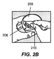
図2A〜図2Gに示す一連の図面に、方法100の詳細を示す。図2Aにおいて、使用者200の強調表示された適用部位202、204のうちの1つが選択される。いくつかの実施形態では、他の適用部位を使用することができる。いくつかの実施形態では、部位準備動作を任意選択的に行うことができる。適用部位202、204を、身体装着型装置をより適切に付着させるように、剃毛し、剥離し、洗浄し、または他の方法で処理することができる。より詳細には、身体装着型装置が付着する使用者の身体の部位における皮膚を、身体装着型装置を受け入れるように準備することができる。たとえば、皮膚を、かみそりで剃毛し、イソプロピルアルコール(IPA)で洗浄し、研磨剤で剥離することができる。機械的剥離要素を使用して、角質の外層を除去し、下の新たな皮膚を露出させることができる。これらの要素には、マイクロファイバ剥離布、軽石または他の研磨鉱物、やすり(rasp/file)型形態の金属スタンプ部品、Scotch−Brite(登録商標)等の合成すり磨き材、角質を除去するために施されはぎ取られる代替的な粘着テープまたはパッチ、および塩、粉砕されたアーモンドの殻、杏仁等の有機研磨要素が挙げられる。同様に、αヒドロキシ酸、βヒドロキシ酸およびサルチル酸等の緩和酸ならびに果物酵素を含む、化学的剥離要素(複数可)を使用して部位を準備することができる。こうした化学的剥離要素(複数可)を、準備パッド、ぬれナプキン、綿棒に組み込むかまたは他の方法で供給することができる。いくつかの実施形態では、アプリケータのエンドキャップは、1つまたは複数の剥離要素を含むことができる。いくつかの実施形態では、エンドキャップを、身体装着型装置が付着する部位の皮膚を剥離するために使用することができる表面を提供するように、凹凸にするかまたは他の方法で成形することができる。適用の前に角質の外層を剥離することにより、身体装着型装置をより長時間皮膚により適切に付着させることができる。
Details of the
図2Bは、ケーシング210からカバー208を取り除くことを含む、装填器または容器206の準備を示す。容器206は、センサアセンブリおよび鋭利物(またはいくつかの実施形態では、電子回路アセンブリ)を保持するケーシング210を含む。図2Cは、アプリケータアセンブリ216から取外し可能アプリケータエンドキャップ214を分離することを含む、アプリケータ212の準備を示す。いくつかの実施形態では、容器206およびアプリケータ212を、包装および輸送を簡略化するように、最初に互いに接続された状態で包装することができる。たとえば、取外し可能アプリケータエンドキャップ214は、容器206の外側の対応する機構に結合するかまたはスナップ式に嵌まるボスまたは他の機構を含むことができる。この接続は、単に、システムの動作のためではなく輸送の目的で2つの部品を合わせて保持するようにのみ作用する。したがって、いくつかの実施形態では、ケーシング210からカバー208を取り除き、アプリケータアセンブリ216から取外し可能エンドキャップ214を分離する前に、初期開梱ステップにおいて、容器206およびアプリケータ212は互いから分離される。
FIG. 2B shows the preparation of the loader or
図2Dに示すように、位置合せ指標218、220が位置合せされると、使用者による組立動作106(図1)が、アプリケータアセンブリ216を容器206内に堅固に押し込んで、センサおよび鋭利物を容器から取り出してアプリケータアセンブリ216のガイドスリーブをロック解除することによって達成される。図2Eにおいて、組み立てられロック解除されたアプリケータアセンブリ216は、適用部位204(または202)に配置され、身体装着型装置適用108(図1)を行うように堅固に押し下げられる。図2Fに示すように、使用済みのアプリケータアセンブリ216が適用部位204から取り除かれると、身体装着型装置222が使用者に付着する。いくつかの実施形態では、図2Gに示すように、身体装着型装置222のセンサによって検出される検体レベルを、受信ユニット226(別法として、「読取ユニット」あるいは「受信装置」、または文脈によっては、使用に応じて、「表示ユニット」、「手持ち式ユニット」または「計器」と呼ばれる)によって、身体装着型装置222内の通信機能(たとえば、送受信器、トランスポンダ等)を介して、無線通信リンク224によって取得することができる。関連情報(たとえば、検体レベル傾向データ、グラフ等)は、受信ユニットのディスプレイ228に提示される。
As shown in FIG. 2D, once the
アプリケータ212、容器206および図2A〜図2Gに示す関連構成要素について、図3および図4により詳細に例示する。さらに、多数の他の変形について詳細に後述する。これらの代替実施形態は、それらの内部作業の範囲では異なるように動作する可能性があるが、関連する使用者の行為は異ならない可能性がある。
The
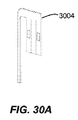
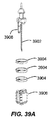
図3を参照すると、アプリケータ212は、取外し可能キャップ214およびアプリケータアセンブリ216を含む。取外し可能キャップ214を、相補的なねじ切り306、306’を介してアプリケータアセンブリ216に固定することができる。エンドキャップ214は、アプリケータ216と嵌合して、アプリケータ216の内部に滅菌包装をもたらす。したがって、アプリケータ216の内部の滅菌を維持するために追加の包装は不要である。いくつかの実施形態では、取外し可能エンドキャップ214の端部(見えず)は、1つまたは複数の開口部を有することができ、それらを、DuPontTMTyvek(登録商標)等の滅菌バリア材料または他の好適な材料によって封止して、シール308を形成することができる。こうした対応により、閉鎖された時にシール308を通して、アプリケータ212のエチレンオキシド(ETO)滅菌が可能になる。いくつかの実施形態では、取外し可能キャップ214の開口部は存在しなくてもよく、取外し可能キャップ214を、滅菌プロセス透過性材料から作製することができ、それにより、アプリケータにキャップが嵌合した時にアプリケータの内部を滅菌することができるが、滅菌プロセスに露出した後のキャップの内部の滅菌を維持することができる。いくつかの実施形態では、ETO滅菌は、電子回路アセンブリ310内の電子回路および関連する接着剤パッチ312と適合性があり、それらをともに、使用者に適用されるまでアプリケータアセンブリ216内に解放可能に保持することができる。図示するように、アプリケータアセンブリ216は、一体的に形成された把持機構316および並進シースまたはガイドスリーブ318を含むハウジング314を含む。
With reference to FIG. 3, the
図4を参照すると、容器206は、カバー402(たとえば箔等の取外し可能材料製)およびケーシング404を含む。ケーシング404の中には、乾燥剤本体412および台またはプラットフォーム408が収容されている。いくつかの実施形態では、乾燥剤本体412は環状形状を有することができ、それにより、乾燥剤本体412をケーシング404内に配置することができ、センサアセンブリ支持体(図4では見えないが図5Aおよび図5Bの512を参照)が、乾燥剤本体412を通して延在することができる。この構成により、容器206は、乾燥剤を収容するためにいかなる追加の高さも必要とすることなく乾燥剤を含むことができる。センサアセンブリ410は、センサアセンブリ支持体512によってスナップフィット式に嵌められるか、または他の方法で保持される。センサアセンブリ410を、プラットフォーム408によって(たとえばフィンガ414を使用して)スナップフィット式に嵌めるかまたは他の方法で保持することも可能である。カバー402が封止されて、容器206を、ガンマまたは放射線(たとえば電子ビーム)滅菌、すなわち、センサアセンブリ410に含まれるセンサの化学的性質と適合性がある手法に晒すことができる。アプリケータ212と同様に、容器206はそれ自体の滅菌包装であり、それにより、ケーシングの内部の滅菌を維持するために、ケーシング404およびカバー402以外の追加の包装は不要である。
Referring to FIG. 4, the
容器206およびアプリケータ212を、異なる滅菌手法によって滅菌することができる。たとえば、容器206に収容されたセンサは、1つのタイプの滅菌プロセスを必要とする可能性があり、アプリケータ212の中身、たとえばアプリケータ212の内部に収容された電子回路は、別のタイプの滅菌プロセスを必要とする可能性がある。2部品の分離可能であるが結合可能なシステム(すなわち、容器206およびアプリケータ212)の有用性により、使用するために2つが合わせて接続される前に、2つの部品のそれぞれの滅菌および滅菌の維持が可能になる。言い換えれば、容器206およびアプリケータ212を別々に封止することにより、これらの2つの構成要素に対する本来は適合性のない滅菌方法の使用が容易になる。たとえば、センサの化学的性質に損傷を与える可能性がある1つのタイプの滅菌を使用して、接着剤パッチ312を含む電子回路アセンブリ310を含むアプリケータ212を滅菌することができる。同様に、電子回路アセンブリ310内の電子回路(および/または電子回路アセンブリ310を使用者の皮膚に付着させるために使用される接着剤パッチ312)に損傷を与える可能性がある別の滅菌プロセスを使用して、内部にセンサを含む容器206を滅菌することができる。能動(すなわち、電子、化学等)素子に対する種々の保存期間属性を考慮すると、さらに他の利点が存在する可能性がある。いくつかの実施形態では、限定されないがETOおよび電子ビーム滅菌等の同じ滅菌技法を使用してすべての構成要素を滅菌することができる。
いくつかの実施形態では、容器206内のプラットフォーム408は、センサアセンブリ410用の改ざん防止バリアとして機能し、使用者がセンサアセンブリ410を直接扱うのを防止する。より詳細には、プラットフォーム408は、センサ、鋭利物および関連するコネクタを保護しかつそれらの保持に役立つように配置されている。いくつかの実施形態では、プラットフォーム408は、使用者による組立動作106(図1)中に長手方向に向けられた力によってアプリケータアセンブリ216から解除されるまで、ケーシング404内で適所にロックされる。言い換えれば、アプリケータアセンブリ216のガイドスリーブ318がプラットフォーム408に抗して下方に挿入されると、スリーブ318は、ロック機構(たとえば留め具)を解除し、プラットフォームがケーシング404内により深く並進するのを可能にする。さらに、ケーシング404の機構を採用して、アプリケータアセンブリ216のガイドスリーブロック機構をロック解除することができる。いくつかの実施形態では、アプリケータアセンブリ216のガイドスリーブ318が、アプリケータアセンブリ216および容器206の位置合せマークが適切に位置合せされて、容器206内に挿入された場合にのみ、容器206のプラットフォーム408をロック解除することができる(図10Cおよび関連する後の文を参照)。
In some embodiments, the
図5Aは、図4のケーシング404の等角断面図である。図5Bは、構成部品を含む図4の容器206の組み立てられた等角断面図である。図5Aおよび図5Bに見ることができるように、プラットフォーム408は、複数のロック機構502によって包囲されている(いくつかの実施形態では、有利には少なくとも1つが設けられている)。ロック機構502の各々は、スロットまたは溝穴508内に受け入れられる舌状部506を備えた片持ちアーム504を含む。そのように配置されて、プラットフォーム408は適所でロックされる。アーム(複数可)504が、矢印PおよびP’によって表される方向に、傾斜部(複数可)510の上に載っているアプリケータアセンブリ216の同心状に配置されたスリーブ318(図示せず)から下方に付勢されると、ロック機構(複数可)502が解除され、プラットフォーム408が、容器206とインタフェースされた結合されたアプリケータアセンブリ216の長手方向軸に沿った方向Bにおいて並進することができる。プラットフォーム408のケーシング404内への並進により、アプリケータアセンブリ216によるセンサアセンブリ410へのアクセスが可能になる。プラットフォーム408がロック解除されケーシング404内に押し下げられるまで、センサアセンブリ410は、使用者が触れるかまたは他の方法で扱う/アクセスすることがないように、他の方法で隔離される。いくつかの実施形態では、使用者によって加えられる力によって押下されるまでプラットフォーム408を保持するように、追加の戻り止め傾斜機構を設けることができる。さらに、こうした動きを制御し、それが平滑かつ直線的であることを確実にするために(すなわち、プラットフォームが傾斜する、固まる等を回避するために)、さまざまなキー溝またはスロット溝案内機構を設けることができる。
FIG. 5A is an isometric cross-sectional view of the
いくつかの実施形態では、スリーブ/傾斜部の関連するロックとのインタフェースは、プラットフォームの位置を維持する戻り止め機構にのみ依存する。そのように構成されて、センサアセンブリの不注意の扱いを回避することができる。プラットフォーム408を空けるために慎重な行為を必要とするように戻り止め(複数可)を調整することができる。
In some embodiments, the sleeve / slope interface with the associated lock relies solely on a detent mechanism that maintains the position of the platform. Such an arrangement can avoid inadvertent handling of the sensor assembly. The detent (s) can be adjusted to require careful action to clear the
いくつかの実施形態では、使用者によってアプリケータアセンブリ216を介して力が加えられると折り畳まれるプラットフォーム408を提供する、代替的な機構および構成を採用することができる。たとえば、図6および図7は、代替的なプラットフォーム602構成を含む代替的な容器600の実施形態を示す。ここでは、折畳み式枠材またはリンク機構604がプラットフォーム602を支持している。このリンク機構604は、リンク機構604のリビングヒンジ設計によって、一体的に案内されかつばね荷重がかけられる。別法として、プラットフォーム602用のガイドとともにコイルばねを採用することができる。アプリケータ216のスリーブ318(図3)またはセンサ取付ユニット606自体の基部を使用して、アプリケータ216によるセンサアセンブリ608のアクセスおよび引上げならびに完成した組み立てられた身体装着型装置222としての合体のための隙間を提供するように、プラットフォーム602を並進させることができる。容器600は、ケーシング610を含み、センサアセンブリ608を湿気から保護する乾燥剤リング612も含むことも可能である。
In some embodiments, alternative mechanisms and configurations can be employed that provide a
図8に、容器800によるセンサ保管および保護に対する別の実施形態を示す。先の実施形態と同様に、この実施形態もまた、環状乾燥剤リング612を含むことができる。ケーシング802が、支持基部804に関連して設けられている。支持基部804は、センサアセンブリ608および枠806を受け入れる。枠806は、枢動ドア808を含む。図示するように、支持基部804は、案内装置としての役割を果たすように枠脚812を受け入れる3つのチャネル810を組み込んでいる。ドア808は、図9Aに示すその上昇/閉鎖位置では、センサアセンブリ608を使用者による接触から保護する。支持基部804と枠806との間で相互作用するらせん状傾斜機構により、図9Bに示すように枠806が下方に移動すると、ドア808が旋回して開放する。同様に、枠806の機構が、枠806が使用者の行為によって押し下げられるまで支持基部804に対してセンサアセンブリ608を保持することができる。
FIG. 8 illustrates another embodiment for sensor storage and protection by the
図5Aおよび図5Bに示す容器実施形態206と同様に、容器800の枠806を、アプリケータスリーブの導入によって適所にロックしかつ解除することができる。支持リング902が、ボスまたは舌状部814に対して、ボス814が各脚812の角度付きの接触面904に沿ったアプリケータスリーブの作用によって内側に付勢されるまで、ロックすることができる。いくつかの実施形態では、脚812を予荷重で外側に付勢することができるが、他の実施形態では、こうした付勢なしにロック/ロック解除機能が作動することができる。図9Aは、ロック形態を示し、図9Bは、構成要素のロック解除/並進関係を示す。
Similar to the
図10A〜図10Nは、容器206を使用して、アプリケータ212を使用するために準備する内部装置機構の実施形態の詳細例を示す。すべて合わせて、これらの図面は、容器206内に保管されたセンサアセンブリ410をアプリケータ212に保管された電子回路アセンブリ310と接続することによって、身体装着型装置222を組み立てる手順例を表している。さらに、手順は、アプリケータ212を、使用者に組み立てられた身体装着型装置222を適用するように準備する。(上述したようなまたは他の)代替容器実施形態で使用するためのこうした行為の変更を、当業者はそれら実施形態を参照して理解することができる。
FIGS. 10A-10N show a detailed example of an embodiment of an internal device mechanism using a
図10Aおよび図10Bは、それぞれカバー402およびキャップ214の除去の方法を示す矢印とともに、容器206およびアプリケータ212をそれらの構成部品とともに示す。ケーシング404から箔カバー402をはぎ取ると、内部のプラットフォーム408がロックされ、それにより、センサ、センサ支持体(プラグとも呼ぶ)、コネクタおよび鋭利物を含むセンサアセンブリ410(見えないが図4参照)を保護する。(これらの構成要素については詳細に後述する。)同様に、アプリケータアセンブリ216からキャップ214を取り除くと、アプリケータ212がロックされる。ロックされる結果、ガイドスリーブ318(見えないが図3を参照)を、アプリケータハウジング314内に折り畳むことができない。
10A and 10B show the
図10Cにおいて、アプリケータアセンブリ216が容器206内にセットされる。2つの構成要素206、216は、機械的位置合せ機構MおよびM’が係合するまで回転しかつ前進し、それによりアプリケータアセンブリ216は容器206内で位置が合い平らに位置する。視覚的位置合せ指標AおよびA’が、使用者が適切な位置合せ位置を迅速に見つけるのに役立つかまたはそのように案内する。いくつかの実施形態では、位置合せ機構MおよびM’が適切に位置合せされない限り、プラットフォーム408を、容器206内に並進するようにロック解除することができないことに留意されたい。図10Dは、機械的位置合せ機構M、M’が係合している構成要素206、216を示す。スリーブ318はプラットフォーム408を通過し、プラットフォーム408は、スリーブ318の内径の内側で同心状に入れ子になっている。
In FIG. 10C,
図10Eおよび図10Fの断面図は、図10Cおよび図10Dで概説した部品の関係を示す。アプリケータアセンブリ216のスリーブ318が容器206のプラットフォーム408の上に設置され下方に押されると、ロック用リブ1002上のプラットフォーム408の周囲に配置されたプラットフォームロック機構502がロック解除され、プラットフォーム408がインタフェースされた構成要素206、216の長手方向軸(「Z」と表記する)に沿って並進することができる。より詳細には、プラットフォーム408の一部が曲がり、矢印Pによって示すようにプラットフォームロックアーム504が内側に変位して、ケーシング404のロック用リブ1002のロック溝穴508を空け、したがって、プラットフォーム408をロック解除する。この時点で、プラットフォーム408はガイドリブ1004によって適所に保持され、ガイドリブ1004は各々、長手方向軸Zの方向にアプリケータアセンブリ216をさらに押下することによって使用者によって加えられるさらなる下方の圧力によって打ち勝つことができる、プラットフォーム408とガイドリブ1004との間の戻り止め機構1006を提供する。
The cross-sectional views of FIGS. 10E and 10F show the relationship of the components outlined in FIGS. 10C and 10D. When the
ここで図10Gおよび図10Hを参照すると、ロック解除されたプラットフォーム418の落下が示されている。図10Gは、長手方向軸Zの方向におけるアプリケータアセンブリ216のさらなる押下を示す。スリーブ318からの力により、プラットフォーム408の一部の内側の半径方向の偏向がもたらされる。その効果は、戻り止めアーム1008が、図示するように内側にかつガイドリブ1004の戻り止め機構1006から離れるように下方に撓むということである。この作用により、プラットフォーム418およびアプリケータアセンブリ216が解放されて容器206内に自然落下する。いくつかの実施形態では、最終的に電子回路アセンブリ310をセンサアセンブリ410に適切に嵌合させスリーブ318をロック解除するために十分な、所定量の運動量がもたらされるように、戻り止めアーム1008を撓ませる力、または言い換えれば、戻り止め機構1006からの抵抗に打ち勝つ力が選択される。いくつかの実施形態では、戻り止め機構1006からの抵抗に打ち勝つ力は、およそ1Nからおよそ23Nである。他の実際的な値が可能である。
Referring now to FIG. 10G and FIG. 10H, falling
図10Hにおいて、プラットフォーム418の戻り止めアーム1008が戻り止め機構1006を越えると、ガイドリブ1004の各々の逃げ面または逃げ溝1010が、スリーブ318およびプラットフォーム418が長手方向軸Z(図10F)に沿って容器のケーシング404内にさらに摺動するかまたは圧縮する際の摺動摩擦を低減するように、プラットフォーム418に対して増大した隙間を提供する。また、特に鋭利部ボス1014を介して事前にセンサアセンブリ410と接触している1つまたは複数の可撓性握持アーム1012が、図10Gの安定化形態から図10Hの解放状態または形態まで移動する。言い換えれば、プラットフォーム418が容器206内にさらに並進すると、センサアセンブリ410の鋭利部ボス1014は、プラットフォーム418の中心開口部から突出し、可撓性握持アーム1012を押しのける。
In FIG. 10H, when the
ここで図10Iおよび図10Jを参照すると、さらなる特徴を示すように、先の図とわずかに異なる切断面を示す断面図が提供されている。図10Iにおいて、スリーブロックアームが、スリーブロック突起1018と係合するように示されている。この係合により、アプリケータアセンブリ216がロックされ、スリーブ318がアプリケータアセンブリ216のハウジング314内に後退するかまたは押し込まれ得ることが防止される。図10Jにおいて、アプリケータアセンブリ216が、長手方向軸Z(図10F)に沿って容器206内にさらに前進すると、スリーブロック解除機構がスリーブロックアーム1016に接触してスリーブロック突起1018から離れるように曲げ、それにより、アプリケータアセンブリ216をロック解除する。図10Iおよび図10Jに示す特定の実施形態例では、スリーブロック突起1018は、電子回路アセンブリ310の支持体1022に形成されていることに留意されたい。
Referring now to FIGS. 10I and 10J, a cross-sectional view is provided showing a slightly different section from the previous figure to show further features. In FIG. 10I, the sleeve lock arm is shown to engage the
プラットフォーム418が図10Jに示すように容器206内で最も低い位置になると、アプリケータアセンブリ216のスリーブ318は完全にロック解除/解放され移動の用意ができる。スリーブロックアーム1016がロック解除するように外側に撓んでいるように示されているが、いくつかの実施形態では、スリーブロックアーム1016を、要素を解放するように半径方向内側に撓むように向けることができる。これは、本発明のさまざまなロック/ロック解除機構に当てはまる可能性がある。しかしながら、本構成は、統合された全体に関して、電子回路アセンブリ310の支持体1022が同軸状に配置されている、有利なフォームファクタおよび最小化された容器ケーシングサイズ(使用者の経験に影響を与える因子)を提供して、利点を提供する。支持体1022に関して、有利には、たとえば、開示内容が参照により本明細書に組み込まれる米国特許出願第13/071,461号明細書に記載されているような一意の支持アーム機構があるように設計されている。
When the
図10Kおよび図10Lでは、アプリケータアセンブリ216のスリーブ318が完全にロック解除されると、戻り止め機構1006(図10H)の抵抗に打ち勝つように使用される力からの長手方向軸Z(図10F)に沿った運動量により、3つの追加の同時の作用がもたらされる。第1に、スリーブ318が、(最も低い位置になるプラットフォーム418と接触しているため)容器206内にそれ以上下降することができなくても、図10Lに示すようにスリーブ318がロック解除されると、アプリケータアセンブリ216のハウジング314、支持体1022および電子回路アセンブリ310は、自由に容器206内に下降し続けることができる。
In FIG. 10K and FIG. 10L, the
第2に、電子回路アセンブリ310が長手方向軸Z(図10F)に沿ってさらに下降すると、センサアセンブリ410は、電子回路アセンブリ310の開口部内に押し込まれ、それにより、センサが電子回路に結合し、身体装着型装置222(図2F)の組立が完了する。いくつかの実施形態では、センサアセンブリ410および電子回路アセンブリ310の嵌合スナップ機構を使用して、封止された信頼性の高い接続を確保するために、構成要素を合わせてロックされ圧縮されたままにすることができる。嵌合スナップ機構の代りに、いくつかの実施形態では、センサアセンブリ410および電子回路アセンブリ310を、軽圧入または他の接続によって結合することができる。しかしながら、スナップ機構の押し込み式相互作用およびロックが有利である。そのため、係合のために跳ね返る精密なロック機構を偏向させるために使用される力もまた最小限になる。
Second, when the
第3に、ハウジング314、支持体1022および電子回路アセンブリ310とともに、鋭利部後退アセンブリ1024もまた、長手方向軸Z(図10F)に沿って容器206内に下降し続け、センサアセンブリ410の鋭利部ボス1014を強制的に受け入れる。鋭利部ボス1014の円錐状頭部は、鋭利部後退アセンブリ1024の可撓性アーム1026の放射状配置を越えるように押される。可撓性アーム1026は、鋭利部ボス1014の頭部の通過する円錐状面に対して強制的に載る際に、外側に曲がる。したがって、それにより、鋭利部ボス1014の頭部が通過すると可撓性アーム1026が適所に跳ね戻る際に、鋭利物は鋭利部後退アセンブリ1024によって係合され、頭部を鋭利部ボス1014の狭窄首部において確実に握持する。鋭利部ボス1014の基部を、可撓性アーム1026の止め制限部または肩部との干渉によって鋭利部後退アセンブリ1024内への挿入を制限するように含めることができることが留意されたい。図10Kは、上記3つの作用が完了する直前の構成を示し、図10Lは、作用が完了した直後の結果としての構成を示す。
Third, along with the
いくつかの実施形態では、センサアセンブリ410の鋭利部ボス1014と鋭利部後退アセンブリ1024との間の接続機構を他の方法で構成することができる。たとえば、鋭利部後退アセンブリ1024は、鋭利部ボス1014の頭部を受け入れるように構成された内側に付勢された可撓性指部材の放射状構成から形成された円錐状チャネルを含むことができ、それにより、頭部がチャネルを通過すると、可撓性指部が鋭利部ボス1014の狭窄首部に適合する。指部がそのように適合すると、鋭利部ボス1014は、鋭利部後退アセンブリ1024によって捕捉される。自動的に力が加わるロックは、部品の間ですべりにくいため、保持力は材料強度のみによって制限される。
In some embodiments, the connection mechanism between the
図10Mを参照すると、図10Lに対するわずかに回転した図が示されている。鋭利部ボス1014が鋭利部後退アセンブリ1024内で係合し、センサアセンブリ410が電子回路アセンブリ310に結合されて、身体装着型装置222の組立てを完成させ、スリーブ318がロック解除された時、プラットフォームロックアーム504および戻り止めアーム1008は容器206の切下げ溝穴1028と係合しており、それによりプラットフォーム418をケーシング404内でロックする。プラットフォーム418とケーシング404との間のこの係合は、容器206の最終的な位置を示し、そこから、装填されたアプリケータアセンブリ216が、使用者に身体装着型装置222を適用するように使用されるために引き出される。
Referring to FIG. 10M, a slightly rotated view relative to FIG. 10L is shown. Engages with a
ここで、アプリケータアセンブリ216は、容器206から取り除かれると、図10Nに示すように「発射する(fire)」用意ができている。したがって、アプリケータアセンブリ216は、図2Eに関連して説明した適用108と同様に使用の用意ができている。ここで、アプリケータアセンブリ216は、容器206との相互作用によってすでにロック解除されており、センサアセンブリ410は電子回路アセンブリ310に結合されている。鋭利物1030は、図示するようにアプリケータアセンブリ216のスリーブ318内に保持される身体装着型装置222から延在している。
Here, when the
図11A〜図11Fは、身体装着型装置222を使用者に適用するようにアプリケータアセンブリ216を「発射」し、鋭利物1030を使用済みアプリケータアセンブリ216内に安全に後退させることを含む、内部装置機構の実施形態の詳細例を示す。すべて合わせて、これらの図面は、鋭利物1030(身体装着型装置222に結合されたセンサを支持する)を使用者の皮膚の中に押し込み、センサを使用者の間質液と有効に接触させたままにして鋭利物を引き抜き、身体装着型装置を使用者の皮膚に接着剤で付着させる手順例を表している。代替的なアプリケータアセンブリ実施形態および構成要素で使用されるこうした行為の変形を、当業者はそれらの実施形態および構成要素を参照して理解することができる。
11A-11F includes “firing” the
ここで図11Aを参照すると、センサ1102が、使用者の皮膚1104のすぐ上で鋭利物1030内に支持されている。スリーブ318に対するアプリケータアセンブ216の動きを制御するために、上部ガイドセクション1108のレール1106(任意選択的にそれらのうちの3つ)を設けることができる。アプリケータアセンブリ216の長手方向軸に沿った適切な下方の力により、戻り止め機構1110によって提供される抵抗が克服され、それにより、鋭利物1030および身体装着型装置222が長手方向軸に沿って使用者の皮膚1104内に(かつその上に)並進することができるように、スリーブ318は、アプリケータアセンブリ216内で戻り止め機構1110によって保持される。さらに、支持体1022の留めアーム1112が鋭利部後退アセンブリ1024と係合して、鋭利物1030を身体装着型装置222に対して適所に維持する。
Referring now to FIG. 11A, a
図11Bにおいて、戻り止め機構1110に打ち勝つかまたは戻り止め機構1110を無効にするように使用者の力が加えられ、スリーブ318がハウジング314内に折り畳まれ、身体装着型装置222を(関連する部品とともに)長手方向軸に沿って矢印Lによって示すように下方に並進させる。スリーブ318の上部ガイドセクション1108の内径が、センサ/鋭利物挿入プロセスの全行程を通して支持アーム1112の位置を制約する。支持体アーム1112の止め面1114の、鋭利部後退アセンブリ1024の相補的な面1116に対する保持により、戻りばね1118が完全に作動されて部材の位置が維持される。
In FIG. 11B, a user force is applied to overcome or defeat the
図11Cにおいて、センサ1102および鋭利物1030は完全な挿入深さに達している。そうする際、支持アーム1112は、上部ガイドセクション1108内径から出る。そして、コイル戻りばね1118の圧縮力により、角度付き止め面1114が半径方向外側に押され、図11Dの矢印Rによって示すように(溝付きまたは他の方法で構成された)鋭利物1030を使用者の体内からかつセンサ1102から引き離すように、鋭利部後退アセンブリ1024の鋭利部支持体1120を駆動するように力を解放する。
In FIG. 11C,
図11Eに示すように鋭利物1030が完全に後退すると、スリーブ318の上部ガイドセクション1108は、最終的なロック機構1120によって固定される。図11Fに示すように、使用済みのアプリケータアセンブリ216は、身体装着型装置222を残して挿入部位から取り除かれ、鋭利物1030はアプリケータアセンブリ216の内側に安全に固定されている。使用済みアプリケータアセンブリ216は、この時点で廃棄の用意ができている。
When the
身体装着型装置222を適用する時のアプリケータ216の動作は、鋭利物1030の挿入および後退の両方がアプリケータ216の内部機構によって自動的に行われる感覚を使用者に提供するように設計されている。言い換えれば、本発明は、使用者が自身の皮膚内に鋭利物1030を手で押し込む感覚を、使用者が体験するのを回避する。したがって、使用者が、アプリケータ216の戻り止め機構からの抵抗に打ち勝つのに十分な力を加えると、アプリケータ216の結果としての作用は、アプリケータが「起動されて」いることに対する自動化された応答であると認識される。すべての駆動力が使用者によって提供され、鋭利物1030を挿入するためにいかなる追加の付勢/駆動手段も使用されないにも関らず、使用者は、鋭利物1030を自身の皮膚に突き刺す追加の力を提供していると知覚しない。図11Cにおいて上で詳述したように、鋭利物1030の後退は、アプリケータ216のコイル戻りばね1118によって自動化される。
The operation of the
動作のさらなる詳細に関して、代替実施形態を、後述する関連手法、組み込まれた主題を検討して他の手法を鑑みて理解することができ、主題の開示のさまざまな態様によって製造された実際のハードウェアを示す図の検討に基づいて、当業者がさらに理解することができる。 For further details of operation, alternative embodiments can be understood in view of other approaches by considering the related techniques described below, the incorporated subject matter, and the actual hardware produced by the various aspects of the subject disclosure. One skilled in the art can further understand based on a review of the figures showing the wear.
図12A〜図12Dを参照すると、ここでは代替的なアプリケータ/容器セット手法が示されている。図12Aに示すように、容器1200は電子回路アセンブリ1202を保持する。これは、センサアセンブリと電子回路アセンブリとの関係が逆転していた上記実施形態とは対照的である。マーカMおよびM’を位置合せすると、アプリケータ1204は容器1200に挿入される。図12Bでは、ユニットは結合されている。図12Cでは、部品は分離されている。最後に、図12Dでは、アプリケータ1204は(たとえば、いくつかの実施形態ではアプリケータ1204内のスリーブ1206をねじることにより、いくつかの実施形態では電子回路アセンブリ1202をアプリケータ1204内に装填する行為により、または何らかの実施形態ではスリーブ1206からロック用ストリップを取り除く行為により)ロック解除され、内部にセンサアセンブリが装填されている組み立てられた身体装着型装置(見えず)との使用の用意ができている。これらのさまざまな代替実施形態を図13A〜図15Fに示す。
Referring to FIGS. 12A-12D, an alternative applicator / container set approach is shown here. As shown in FIG. 12A, the
図13A〜図13Cは、スリーブロック機構1206に関する図12A〜図12Dのアプリケータ1204の使用をさまざまに示す。図13Aは、閉鎖窓1208によって示されるロックされたスリーブ1206を示す。スリーブ1206をロック解除するためにアプリケータ1204の残りの部分に対してスリーブ1206をねじった後、図13Bに示すように、アプリケータ1204が使用の用意ができると、視覚的支持(たとえば開放した窓1208’)が見える。使用時、図13Cに示すように、スリーブ1206がアプリケータ1204内に折り畳まれて、ユニットが圧縮される。
Figure 13A~ Figure 13C is variously show the use of the
図14Aおよび図14Bは、取外し可能ロック用ストリップ1402を含む代替的なアプリケータ1400の実施形態を示す。ロック用ストリップ1402がスリーブ1406の周囲の適所にあって、スリーブ1406をアプリケータ1400内に押し込むことができない。ストリップ1402は、プルタブ1404と、プルタブ1404を取り除かれるまで適所に維持する接着剤または他の締結部材とを含み、アプリケータ1400は使用の用意ができている。
14A and 14B show an
図15A〜図15Fは、容器1500と使用されるための図14Aおよび図14Bのアプリケータ1400の準備を示す。容器1500からカバー1502が取り除かれ、アプリケータ1400からキャップ1506が取り除かれると、アプリケータ1400は容器1500内に挿入されて、図15Bおよび図15Cに示すように、電子回路アセンブリ1504をアプリケータ1400内に装填し、センサアセンブリ(図示せず)を電子回路アセンブリ1504に嵌合させる。装填されると、図15Dに示すように、アプリケータ1400は容器1500から取り除かれる。図15Eは、組み立てられた身体装着型装置222が装填されかつセンサ/鋭利物挿入の用意ができているアプリケータ1400を示す。ロック用ストリップ1402がスリーブ1406から取り除かれ、開放した用意指標1208’は、アプリケータ1400が使用されるために用意ができていることを知らせる。図15Fは、こうした作用が、アプリケータ1400から使用者の皮膚の上に身体装着型装置222を移送する際に行われた後のシステムを示す。
15A-15F show the preparation of the
図16Aおよび図16Bは、図15A〜図15Fにおける容器1500の特徴のそれぞれ断面図および詳細図である。具体的には、身体装着型装置1604が、容器1500内に、接着剤パッチ1602およびその裏当て1606とともに示されている。裏当て1606は、らせん状に切断されてボスに取り付けられ、それにより、身体装着型装置1604が容器1500から移送された時、剥離された裏当て1606は残される。このように、接着剤パッチ1602は裏当て1606によって覆われたままであり、そのため、容器1500に不注意で付着しない。
16A and 16B are a cross-sectional view and a detailed view, respectively, of the features of the
図16Aおよび図16Bのらせん状の剥離裏当て手法に対する代替形態として、図17Aおよび図17Bは、身体装着型装置1706の接着剤が裏打ちされたパッチから別個の剥離「バタフライ」ウィングまたは左右対称ライナパネルを捕捉する、代替的な容器1702構成を示す組立斜視図である。各々、剥離された裏打ちライナ切片を把持する2部品基部1704が設けられている。当然ながら、基部1704は、容器ケーシング内に嵌合するように適合されている。いくつかの実施形態では、容器1702を異なるように構成することができる。図17Aに示す変形例では、裏打ちの把持に役立つようにトラクション/トレッド1708が設けられている。図17Bに示す変形例では、裏打ちの除去に役立つように傾斜部1710が設けられている。別の変形例では、基部は、「クラムシェル」構成でリビングヒンジを組み込んだ一体型成形であり得る。裏打ちライナ切片(複数可)を、中心線に沿ってまたはずれた位置で捕捉することができる。いかに構成されても、基部1704は、基部1704および容器1702、スナップまたは他の機構に関連する相補的なバンドおよびリブインタフェース機構によって適所にスナップ式に嵌まることができる。本明細書に記載する他のアセンブリと同様に、これらの機構を、別法として、圧入し、超音波溶接し、または他の方法で適所に固定することができる。
As an alternative to the spiral peel backing approach of FIGS. 16A and 16B, FIGS. 17A and 17B show a separate peel “butterfly” wing or symmetrical liner from the adhesive lined patch of the body
図18は、図15A〜図15Fに示すアプリケータおよび容器のセットの特徴を示す断面図である。図18に示す実施形態は、上記の代替装填手法に関連して説明した特徴のうちのいくつかを含む。しかしながら、実施形態の手法は簡略化されている。最も顕著には、容器1806は、能動的/可動構成要素を有していない。アプリケータ1800が容器1806内に押し下げられると、身体装着型装置1808は、組み立てられ(たとえば、センサアセンブリが電子回路アセンブリと嵌合し)、容器1806から(たとえば解除可能なラッチを用いて)解放され、(たとえばラッチアームを使用して)アプリケータ1800によって保持される。この実施形態は、他の実施形態と同様に身体装着型装置1808の接着剤を露出させる必要がないという利点を提供する。さらに、身体装着型装置1808の位置は、センサアセンブリ挿入のための安定した面を提供する。アプリケータに身体装着型装置が事前装填される他の実施形態は、上述した引渡し(hand−off)を行う必要がないという利点を提供する。また、鋭利物用の保護具を使用するかまたは含めることがなくなる。
18 is a cross-sectional view illustrating features of the applicator and container set shown in FIGS. 15A-15F. The embodiment shown in FIG. 18 includes some of the features described in connection with the alternative loading approach described above. However, the method of the embodiment is simplified. Most notably, the
図19Aおよび図19Bは、針ガード1904に関連するセンサアセンブリ1902を示す。使用時、針ガード1904の遠位インタフェース機構(たとえばかえし)が、身体装着型装置の組立中に容器内の相補的な分割リングまたは他の機構によって捕捉される。そして、アプリケータが容器から分離されると、針ガード1904は容器内に保持され、鋭利物は露出する。いくつかの実施形態では、針ガード1904を、鋭利物を解放可能に固定する熱可塑性エラストマ(TPE)挿入物とともにポリプロピレンから作製することができる。他の材料を選択することができる。
19A and 19B show a
本発明の他の要素の構成に対して他の材料を選択することができる。たとえば、アプリケータハウジングを、ポリカーボネートまたは他の何らかの実際的な材料から作製することができる。ガイドスリーブ、容器等を、(摺動部品の滑らかさの理由で)アセチルから構成することができる。あらゆる部品も、射出成形し、熱成形し、または他の方法で製造することができる。 Other materials can be selected for the configuration of other elements of the invention. For example, the applicator housing can be made from polycarbonate or some other practical material. Guide sleeves, containers, etc. can be composed of acetyl (for reasons of smoothness of the sliding parts). Any part can be injection molded, thermoformed, or otherwise manufactured.
センサアセンブリの電子回路アセンブリへの引渡しに関して、図20Aおよび図20Bは、電子回路アセンブリ2004を持ち上げて身体装着型装置を形成する要素2002に、センサアセンブリボス2006に保持する方法を示す。ばね枠材2008が、センサアセンブリ2006のへりに留まり、輸送および取扱い中にセンサアセンブリ2006をアプリケータ内に保持する。アプリケータおよび容器が1つにされると、レバーアーム2010が身体装着型装置2004に接触し、関連するばね枠材(または「ばねアーム」)が接続部をセンサアセンブリのへりから離れるようにねじって回転させ、それによりセンサアセンブリを解放する。センサアセンブリボスの面取り部は、1つまたは複数(たとえば3つの)トルクを与えるばね枠材2008の位置合せおよび適切な作動を確実にするのに役立つことができる。
With respect to delivery of the sensor assembly to the electronic circuit assembly, FIGS. 20A and 20B illustrate how the
図21A〜図21Cは、代替的な引渡し手法を示す。この実施形態では、軽スナップフィットを備えたセンサアセンブリつかみ具2106が、センサアセンブリ2104を握持し電子回路アセンブリ2102に接続するように向ける。センサアセンブリ2104が電子回路アセンブリ2102内に堅固に嵌められると、センサアセンブリつかみ具2106は、その把持に打ち勝つ大きさの力で後退する。こうした手法は、(スナップ機構を鋭利部ハブ/ボス内に組み込むことができることを考慮して)必要な部品の数を低減することにより簡略化を提供する。
電気的接続の詳細
上記代替実施形態からのさまざまなハードウェアオプションの選択は、少なくとも部分的にセンサアセンブリ構成によって決まる。そして、センサアセンブリ構成は、センサアセンブリと電子回路アセンブリとの間に電気接点を確立するために選択される機構とともに、接点を封止するために使用される方法によって決まる。複数の有利な代替的実施形態を、図22〜図48に示す。
21A-21C illustrate an alternative delivery technique. In this embodiment, a
Electrical Connection Details The selection of various hardware options from the above alternative embodiments is determined, at least in part, by the sensor assembly configuration. The sensor assembly configuration then depends on the method used to seal the contacts, as well as the mechanism selected to establish an electrical contact between the sensor assembly and the electronic circuit assembly. A number of advantageous alternative embodiments are shown in FIGS.
第1例を図22に示す。ここでは、センサ2202に細長い「尾部」セクションが設けられている。尾部の遠位端は、鋭利物によって案内される皮膚面を通して挿入される。センサ2202の近位部は、「旗」型コネクタ領域を含む。3つの炭素ドープ(導電性のため)シリコーン電気コネクタ2204が、センサ2202の電気接点とインタフェースするように設けられている。各コネクタ2204の分割「V字」部が、センサ2202の電気接点を受け入れる。電子回路アセンブリに組み込まれた回路基板との電気接点に対して、各コネクタ2204の反対側の可撓性突起(nubbin)が設けられている。ハウジング2210に挿入されると、センサ2202およびコネクタ2204は、有利に、接着剤を用いて、封止され、包み込まれ、または埋め込まれる。エポキシ、UV硬化性または別のタイプの誘電体(非導電性)化合物を使用することができる。概して、選択される化合物は、機構の周囲に流れてセンサ2202をそのハウジング2210内で完全に封止して漏れを回避することができるような粘性を有している。こうした手法により、流体侵入による汚染および/または電流漏れが回避される。図23Aおよび図23Bは、図22のセンサコンポーネントのそれぞれ組立斜視図および最終組立断面図である。センサ2202の尾部は、鋭利物2206内に支持され、鋭利物2206はコネクタハウジング2210を通って延在する。センサ2202の電気接点は容器2204内に設置され、アセンブリは、ハウジング頂部2208を含むハウジング2210内に封止される。
A first example is shown in FIG. Here, the
図24Aおよび図24Bは、図23Aおよび図23Bのセンサアセンブリ2300と使用される回路基板コンポーネントのそれぞれ上面斜視図および底面斜視図である。各々に、カスタム印刷回路基板(PCB)2402が示されている。PCB2402は、マウント2408とともにバッテリ2406、特定用途向け集積回路(ASIC)2410、または他の適切な処理ユニット、および熱電対を含む他のさまざまな回路を有している。PCB2402は、その表面に、図23Aおよび図23Bのセンサアセンブリ2300を受け入れるスナップ機構を備えたハウジング2404を有している。PCB2402の反対側には、熱かしめ2412が、ハウジング2404を取り付ける方法を示している。
24A and 24B are top and bottom perspective views, respectively, of circuit board components used with the
図25Aおよび図25Bを参照すると、いくつかの実施形態では、身体装着型装置2502が、ポリマー「マクロメルト(macromelt)」(たとえば、ポリアミド系熱可塑性ホットメルト)または他の化合物でオーバーモールドし、その後、それに剥離可能なライナによって接着剤パッチを取り付けることによって形成される。完成した身体装着型装置2502は、図25Aおよび図25Bに示すように相補的なセンサアセンブリ2300と嵌合すると提供される。こうしたアセンブリの内部では、図26の組立図に示すようにシールまたはガスケット2604を含むことが望ましい場合がある。図27Aにおいて断面で示し、図27Bで拡大して示されるように、ガスケット2604は、有利には、各回路接続/突起の周囲を含む重要な領域において圧縮し封止を確保するために別個のリング/リム要素を含む。
Referring to FIGS. 25A and 25B, in some embodiments, a
図28A〜図28Fは、別の有利なセンサ2802およびセンサマウントまたはコネクタ2804構成を示す。この実施形態は、先の手法に似ているが、センサ接続「旗」に曲げおよび湾曲が与えられて構成されている。これにより、およそ三角形の封体内の包装および封止が可能になり、コネクタの長さが短縮する。そうすることにより、センサアセンブリ本体が概してより小型になり、関連するコンポーネントすべてを小型化することが可能になる。しかも、それはそれほど製造を複雑にしない。図28Aは、コネクタ2804内に嵌合するように成形される前のセンサ2802を示す。図28Bは、曲がって湾曲したセンサ接続「旗」を示す。図28Cは、コネクタ2804に挿入される際のセンサ2802の相対的な向きを示す。図28Dは、センサ2802を保持しコネクタの電気接点をセンサ2802の電気接点に対して押圧するようにコネクタ2804内に圧入される楔2806を示す。図28Eは、コネクタ2804に挿入される際の鋭利物2808の相対的な向きを示し、図28Fは、電気接点を封止するために使用されるポッティング材2810(たとえばUVポッティング材)を含む完成したセンサアセンブリを示す。
28A-28F illustrate another
図29A〜図29Dに示すセンサ手法に関連して代替実施形態が企図される。結合部2904によって支持される垂直に配置された「旗」コネクタ部を備えるセンサ2902を使用して、結合部2904は、PCB2914に取り付けられるコネクタブロック2908内にスナップ式に嵌まるように構成されている。コネクタブロック2908は、センサ2902の接点部を受け入れるコネクタソケット2910を有している。コネクタブロック2908はまた、結合部2904に、コネクタソケット2910内にセンサ2902を保持するスナップフィットタブ2906を受け入れる結合機構2912を有している。
Alternative embodiments are contemplated in connection with the sensor approach shown in FIGS. 29A-29D. Using a
図30A〜図30Cに示すセンサ手法に関連して、別の代替実施形態が企図される。ここでは、接続要素および別個のばね接点(上述したように金属であってもエラストマであっても)に対する必要をなくす設計が提供されている。さらに、本手法は、両側に接点があるセンサを、折り畳んだ後に片側に接点があるセンサに有効に変えるという利点を提供する。図30Aに示すセンサ3004は、最初に、分割接点領域において第1方向に面している2つの電気接点と、反対側の第2方向(視界によって隠されている)に面している1つの接点とを有している。図30Bに示す向きに、折り畳まれ、任意選択的に締め付けられ、接着されまたは他の方法で取り付けられると、電気接点のすべては同じ向き(たとえば図面の下方)に面している単一面に位置する。センサ3004を制約しかつ/または封止するようにハウジング(図示せず)内に固定されて、センサ3004は、図30Cに示すようにPCB3002上の電気接点に結合される。
In connection with the sensor approach shown in FIGS. 30A-30C, another alternative embodiment is contemplated. Here, a design is provided that eliminates the need for connecting elements and separate spring contacts (whether metal or elastomer as described above). Furthermore, this approach offers the advantage of effectively changing a sensor with contacts on both sides to a sensor with contacts on one side after folding. The
こうした手法は、いくつかの実施形態では、図31に示す身体装着型装置3102の変形例に対してより薄い(たとえば薄型の)身体装着型装置を含む。低減した厚さ寸法を高さHによって表す。図31において、旗型センサが、ハウジング内に別個の電気コネクタとともに示されている。図31における「積み重ね高さ」は、ハウジングとともにこれらのコネクタを含む。図30に示す手法により、センサ3004の上方のコネクタ高さをなくすことができる。したがって、機能性を失うことなく要素がなくなる。さらに、部品がなくなることにより、コストと、センサ3004とPCBとの間の(少なくとも図22に示すようなエラストマコネクタ等を含むことに対して)インピーダンスが低減する。別の有用な態様は、両側に接点を有するセンサを、センサにビアまたは穴を必要とすることなくPCBに接続することができ、それにより、電気接点の封止の考慮および容易さに役立つ、ということである。
Such an approach, in some embodiments, includes a thinner (eg, thinner) body-worn device relative to the variation of the body-worn
図32Aおよび図32Bは、2つの追加のセンサ構成を示す。これらの実施形態では、両側に接点を有するセンサ3202、3212は分割され反対方向に曲げられて、電気接点3204、3214を単一面または平面上に向ける。上述したように、電気接点3204、3214を単一平面上に向けることにより、電気接続の封止の容易さが促進される。さらに、全体的なセンサアセンブリの高さを、他の手法に対して低減することができる。導電性接着剤、導電性フィルムおよび/または機械的接点のいずれかを使用して、そのように配置されたセンサ接点と電気的に接続することができる。
32A and 32B show two additional sensor configurations. In these embodiments,
図33A〜図33Gは、電気接点がすべて片側にある薄型多層センサ構成とその構造のいくつかの詳細とを示す。図33Aおよび図33Bは、センサ3300のこの実施形態の両側とその全体的な形状とを示す。例としてのセンサ3300は、鋭利物によって最初に支持され、その後、身体装着型装置の適用時に皮膚の下の使用者の間質液または真皮空間内に配置される、尾部3302を含む。尾部3302は、間質液と接触し、間質液内の検体濃度を測定するために使用される電気信号を検知する(たとえば送受信する)ように使用され、電極3304、3306、3308を有している。センサ3300はまた、センサ3300の一方の側にすべてが配置され、導電トレース(図33Aおよび図33Bでは見えないが図33Fを参照)を介して電極3304、3306、3308と電気通信する、電気接点3312、3314、3316を含む、電気接点部3310も有している。電気接点部3310は、後述するコネクタ支持体内に確実に保持されかつ封止されるのを容易にするような形状であることも留意されたい。たとえば、電気接点部3310は、本明細書において、電気接点部3310が、嵌合機構を含むコネクタ支持体に固定して保持されるのを可能にするタブ3310Aおよび切欠き3310Bとして示される、摩擦嵌め、締り嵌め等によってコネクタ支持体に固定されるようにセンサを保持する固定機構を含む。
Figures 33A-33G show a thin multi-layer sensor configuration with all electrical contacts on one side and some details of its construction. FIGS. 33A and 33B show both sides of this embodiment of
センサ3300はまた、電気接点部3310が電子回路アセンブリの回路基板に対して平行に配置されるのを可能にし、電子回路アセンブリ内の比較的平坦な形状または薄型を容易にする、曲げ可能部3318も含む。曲げ可能部3318はまた、尾部3302が電子回路アセンブリから下方に延在するのも可能にし、それにより、電気接点部3310が回路基板に対して平行に位置する間に、尾部3302を使用者の皮膚の下方に挿入することができる。最後に、センサ3300は、センサ3300がセンサアセンブリのコネクタ支持体に固定して保持されるのを可能にする枠材部3320を有している。枠材部3320はまた、図35Dおよび関連する文において後述するように、尾部3302を鋭利物のチャネル内に押し込む付勢力を加えるように片持ち点も提供する。
図33Cは、センサ3300の側面図を示す。Dが付されている囲まれた部分を、図33Dにより詳細に示す。図33Dは、センサ3300の尾部3302の最遠位部の拡大側面図を提供する。Eが付されている囲まれた部分を、図33Eにより詳細に示す。図33Eは、尾部3302の電極3304、3306、3308のさらなる拡大図を提供する。図33Eに見ることができるように、電極3304、3306、3308は、基板3322上の層として形成されている。基板3322は、可撓性の非導電性誘電体材料から作製される。いくつかの実施形態では、基板3322に対して、透明な光沢の強い熱安定ポリエステルフィルムを使用することができ、導電性カーボンインクを使用して、電極3304、3306、3308に対して使用されるトレース層を生成することができる。他の実施形態では、基板3322に対してポリマーまたはプラスチック材料およびセラミック材料等、トレース層に対して炭素または金等、他の材料を使用することができる。
FIG. 33C shows a side view of
電極3304、3306、3308を互いから絶縁するために、電極3304、3306、3308の間にかつそれらの上に、誘電体層3324、3326、3328が配置される。いくつかの実施形態では、誘電体層3324、3326、3328に対して、紫外線(UV)光硬化性誘電体材料を使用することができる。他の実施形態では、他の実際的な材料を使用することができる。図示する特定の実施形態例では、電極3304は対極であり、電極3306は作用電極であり、電極3308は参照電極である。参照電極3308はまた、二次導電層3330、たとえばAg/AgCl層も含む。いくつかの実施形態では、二次導電層3330の側面は、誘電体層3328によって覆われており、それにより、基板3322の側縁に沿って延在する二次導電層3330の側面のみが、誘電体層3328によって覆われず、したがって、動作可能に使用される時に環境に露出する。こうした実施形態では、誘電体層3328は、二次導電層3330の側面全体を覆い、すなわち、二次導電層3330の側面の100%が誘電体層3328によって覆われる。したがって、誘電体層3328は、導電層3330と少なくとも同じ幅および少なくとも同じ長さを有している。
センサ3300の構成、寸法、化学的性質および製造方法のさらなる詳細を、2012年6月18日に出願され、全体としてかつすべての目的で参照により本明細書に組み込まれる、「Connectors For Making Connections Between Analyte Sensors And Other Devices」と題する米国特許出願第13/526,136号明細書に見ることができる。
Further details of the construction, dimensions, chemistry and manufacturing method of the
図33Fは、電気接点3312、3314、3316を電極3304、3306、3308に接続する導電トレースライン3332、3334、3336の種々の層を表す隠れ線を含む、図33Aおよび図33Bのセンサ3300の図を示す。センサ3300の反対側の電極に対する電気接点3314、3316は、ビア3338、3340(2つのみ記号を付す)を使用してそれぞれの導電トレース3334、3336に結合される。図33Gは、図33Fの線GGに沿って取り出されたセンサ3300の断面図である。図示するように、誘電体層3324によって覆われる導電トレース3332は基板3322の一方の側にあり、誘電体層3326によって分離されかつ誘電体層3328によって覆われる導電トレース3334、3336は、基板3322の反対側にある。電気接点3314、3316は、誘電体層3328の開口部を介してアクセス可能である。
FIG. 33F shows a diagram of
図33H〜図33Jは、3つの代替的なセンサ設計3342、3344、3300を比較のために並べて示す。特に、センサ3342は、電子回路アセンブリのPCBに物理的に取り付けるためのリベットまたは他の締結具を受け入れる開口部3346を有している。センサ3342の詳細は、2012年6月18日に出願された、「Connectors For Making Connections Between Analyte Sensors And Other Devices」と題する先に組み込まれた米国特許出願第13/526,136号明細書に提供されている。センサ3344および3300は、図34A〜図35Dに関して後述する代替的なコネクタ構成と使用するのに適している。
33H-33J show three
ここで図34A〜図35Dを参照すると、回路基板を、図33A、図33Bおよび図33Jに示すようなセンサ3300に接続する代替的なコネクタ構成が記載されている。図34Aに示すように、可撓性一体型シールまたはコネクタ3402が、シリコーンまたは他の実際的な弾性材料で成形されている。その中に、回路基板に接続するための電気接点3410を提供する、別個のドープされたシリコーン導電性素子が固定される。いくつかの実施形態では、導電性素子を別法として、適所にオーバーモールドするかまたはインサート成形することができる。その結果が、2つの(図示するような)対称的なセクションを接合するリビングヒンジを組み込んでいる、略可鍛性/可撓性ハイブリッド接続および封止ユニットまたはコネクタ3402である。別法として、2部品設計が可能である。しかしながら、単体設計では、装置を、ヒンジセクションとは反対側に単一の留めボスまたはポスト3412を使用して適切に固定することができる。いくつかの実施形態では、2つ以上のポストを使用して、センサ3300の接点部の両側の周囲に折り畳まれかつそれらを封止するコネクタ3402を固定することができる。したがって、センサ3300の誘電体コーティングが機能しなくなる(たとえばピンホール漏れ)場合であっても、コネクタ3402は、センサ接点3312、3314、3316が湿気またはあらゆる汚染物質から保護されることを確実にする。一体型設計はまた、例示したように組立ても容易にし、そこでは、可撓性コネクタ3402は、一方の側がポスト3412に位置して、剛性または半剛性ハウジングまたはコネクタ支持体3404に固定される。そして、センサ3300は、挿入され、センサ3300の曲げ可能部3318においておよそ90度曲げられる。曲げられると、その後、センサ3300は、図34Cにおいて矢印Sによって示すように、コネクタ3402を折り重ねることにより、コネクタ3402の上部によって捕捉される。コネクタ3402は、左右対称に示されているが、いくつかの実施形態では、電気接点3410のいくつかは必要でない可能性もあるため、コネクタ3402を特定方向の向きに形成することができる。いくつかの実施形態では、センサの電気接点3312、3314、3316のすべてを、センサ3300の片側に設けるか、または他の実施形態ではセンサ3300の両側に設けることができる。
Referring now to FIGS. 34A-35D, an alternative connector configuration for connecting a circuit board to a
図34Dに示すように、いくつかの実施形態では、コネクタ3402の上面は、コネクタ3402の電気接点3410を取り囲むコネクタ3402の上面縁に配置された隆起したへり3418を有している。隆起したへり3418を、コネクタ3402を形成ししたがってセンサアセンブリが電子回路アセンブリ内に挿入されると圧縮可能な、エラストマ材料で一体的に形成することができる。別法として、隆起したへりを、コネクタ3402の上面のガスケットまたはOリングとして具現化することができる。隆起したへり3418は、センサと電子回路アセンブリとの間のいかなる電気的接続も確立される前に、コネクタ3402の電気接点3410およびPCBの電気接点の周囲にシールが形成されるのを確実にするように機能する。したがって、隆起したへり3418は、センサアセンブリが電子回路アセンブリと嵌合する際に、組立ての順序がシールを生成することと、その後、電気的接続を生成することをと含むことを確実にすることにより、短絡に対するフェイルセーフを提供する。
As shown in FIG. 34D, in some embodiments, the top surface of the
いずれの場合も、センサ3300がシール3402に捕捉されると、その後、鋭利物3408が導入され、そのハブ3414は、図34Dに示すようにコネクタ支持体3404と接触する。図35Aは、鋭利物3408をコネクタ支持体3404に挿入する前の鋭利物3408の向きを示す。図35Bおよび図35Cは、鋭利物3408のセンサ3300に対する関係の断面概略図を提供する。特に、コネクタ支持体3404に挿入されると、鋭利物3408は、センサ3300の尾部3302を包囲し支持する。図35Dにおいて、センサ構成のさらなる詳細が明らかである。特に、センサ3300を鋭利物3408のチャネル内に位置決めし付勢するためにコネクタ支持体3404の表面に当接する付勢機構が示されている。特に、枠材部3320は、コネクタ支持体3404の矢印3502において表面に当接し、それにより、付勢機構3508は、矢印3504において支点として作用し、矢印3506においてセンサ3300の尾部3302を鋭利物3408内に押し込む。
In either case, once
いくつかの実施形態では、センサ3300の湾曲セクション3508は、コネクタ支持体3404の対応する表面の上に重なり、センサ3300に対して挿入深さを制限する(すなわち深さ止めを提供する)役割を果たすことができる。挿入深さを含むセンサ3300の垂直配置はまた、シール3402半体の間の関係に基づいて制御される。本明細書で考察する他のセンサアセンブリハウジング/支持体に関して上述したように、図35Cのセンサアセンブリもまた、身体装着型装置内の電子回路アセンブリのソケットとのその厳密な関係のためにさまざまなクリップまたはスナップ機構を有するができる。
In some embodiments, the
図34A〜図34Dおよび図35A〜図35Dに関して説明したものに対する関連構成を、図36〜図38に示す。図36において、同じ側にすべての電気接点があるセンサ3300が、コネクタ支持体3604に挿入されるように鋭利物3602とともに示されている。コネクタ支持体3604は、エラストマ(たとえばシリコーン)シール裏当てを有している。こうしたセンサアセンブリセットが容器内に(または別法としてアプリケータ内)に入ると、センサアセンブリをセンサ電子回路に結合して身体装着型装置222を形成することができる。図37に示すように、センサアセンブリ3702は、ソケット3704のエラストマ本体の電気接点ともに第2エラストマユニットを含むソケット3704内に嵌合するような形状である。図37において、ソケットをより明確に表示することができるように、電子回路アセンブリの筐体は示されていないことに留意されたい。ソケット3704は、あらゆる実際的な方法を介して回路基板3706に取り付けられる。ソケット3704および/またはコネクタ支持体3604は、電気接点が合わせて緊密に押され、ソケット3704およびセンサアセンブリ3702内で封止されることを確実にするようにさまざまな結合機構(たとえばスナップフィット式のへりおよびフック機構)を含むことができる。センサアセンブリ3702がソケット3704内に受け入れられると、身体装着型装置(たとえば、図38に示すように回路基板3706および接着剤パッチ3802の周囲に完全なオーバーモールドされた筐体を含む)は使用の用意ができている。
Related configurations to those described with respect to FIGS. 34A-34D and 35A-35D are shown in FIGS. 36-38. In FIG. 36, a
上述した電気接点/コネクタ手法は「方向性」がある。言い換えれば、センサアセンブリが電子回路アセンブリと嵌合する前、2つは、互いに対して長手方向にかつ回転方向に位置合せされる。いくつかの実施形態では、結合構成は「無方向性」であり、センサアセンブリを、2つを回転方向に位置合せすることなく電子回路アセンブリに嵌め合わせることができる。たとえば、図39Aおよび図39Bに示すセンサアセンブリ構成は、こうした手法を提供する。コア支持体3906に取り付けられた別個の導電性(たとえば任意選択的に金属)バンド3904が、図39Aおよび図39Bに示すようにセンサ電気接点3908に連結する。組み立てられたユニット(すなわちセンサアセンブリ3910)は、鋭利物3902が適所にある状態で、電子回路アセンブリ4002のソケットに受け入れられ、図40に示すように身体装着型装置を形成する。いくつかの実施形態では、電子回路アセンブリ4002の回路基板上のブラシ型接続部4004は、導電性バンド3904の個々のレベルに達する。こうしたセンサアセンブリ3910を、電子回路アセンブリ4002のソケット内にあらゆる半径方向/回転方向の向きに挿入することができる。
The electrical contact / connector method described above is “directional”. In other words, before the sensor assembly mates with the electronic circuit assembly, the two are aligned longitudinally and rotationally with respect to each other. In some embodiments, the coupling configuration is “non-directional” and the sensor assembly can be mated to the electronic circuit assembly without aligning the two in the rotational direction. For example, the sensor assembly configuration shown in FIGS. 39A and 39B provides such an approach. A separate conductive (eg, optionally metal)
「反転した」手法を、図41A〜図41Cのセンサアセンブリ4100に示す。ここでは、回路基板4102は、ソケットコネクタ4104の内径内に配置された、積み重ねられた導電性エラストマOリング4106の配置を有するソケットコネクタ4104を含む。センサ支持体4108が、センサ4112の電気接点4110を半径方向外側に面している対応する積み重ねで保持するように適合されている。センサ支持体4108がソケットコネクタ4104に挿入されると、導電性エラストマOリング4106は、図41B(導電性エラストマOリング4106がより明確に見えるようにソケットコネクタ4104は図示していない)にかつ図41Cの断面図に示すようにセンサの電気接点と垂直に整列する。いくつかの実施形態では、センサ4112の電気接点4110を、接点のすべての同じ側にしてセンサを巻き上げるか、または図40に関連して示す反対側に向けられた折り重ね/巻き手法(ただし垂直に向けられている)を使用することによって形成することができる。他の手法を同様に利用することができる。いずれの場合も、センサの電気接点は、360度未満の範囲を定め、一方で、回路基板上の導電性エラストマOリングは、多レベル包囲関係を提供する。図39A〜図40に関連する手法と同様に、こうしたセンサアセンブリ4100を、電子回路アセンブリ4102のソケットコネクタ4104内にあらゆる半径方向/回転方向の向きに挿入することができる。
An “inverted” approach is shown in the
図42〜図44に示す実施形態における回路基板4404に関連するセンサ接続は、同心リングで配置される。センサ4202は、ハウジング部材4206および基部4208内に保持される電気接点4204を含む。電気接点4204は、「マイクロばね」ワイヤフォームコネクタを含む。これらのばねは、別個の最上ループとともにコンプライアンスを提供する。各電気接点4204は、回路基板結合部4302の異なる同心導電トラック4304に対応する中心からの異なる半径方向距離に配置される。したがって、回路基板結合部4302に対するセンサアセンブリ4200の回転方向の向きに関らず、センサ4202の電気接点4204は、正確な同心導電トラック4304と整列する。ばねに対して非常に微細なワイヤを使用することができ、それにより容易に小型化されるシステムが製造される。
The sensor connections associated with
ここで図45Aおよび図45Bを参照すると、同心電子回路アセンブリ接続と採用することができる別の無方向性センサアセンブリ接続手法が示されている。図45Aおよび図45Bの等角上面図および底面図に示すように、センサ4504は、接点が異なる放射状経路または弧に沿って配置されて、およそ90度曲がり、2つの対向するディスク4502、4506によって支持される導電性エラストマ接点4508と連結する。エラストマ接点4508のうちの2つは一方のディスク4506に固定され、センサビアを貫通するように構成された第3接点は、他方のディスク4502に固定される。図46Aに示すように、その後、このセンサアセンブリ4500を、センサアセンブリ4500の放射状に配置された導電性エラストマ接点4508を回路基板4606に接続する同心トラックを含む回路基板結合部4604によって受け入れることができる。筐体4608は、回路基板4606を支持する基部にスナップフィット式に嵌まるかまたは(たとえば接着剤/溶接を使用して)付着する。図46Bに組み立てられた身体装着型装置4600を示す。
Referring now to FIGS. 45A and 45B, there is shown another non-directional sensor assembly connection technique that can be employed with concentric electronic circuit assembly connections. As shown in the isometric top and bottom views of FIGS. 45A and 45B, the
ここで図47A〜図47Cを参照すると、代替的なセンサアセンブリ/電子回路アセンブリ接続手法が示されている。図示するように、センサアセンブリ4702は、センサ4704、コネクタ支持体4706および鋭利物4708を有している。特に、センサアセンブリ4702は、図34A〜図34Dに示す実施形態(すなわち、シール3402なし)と同様に、コネクタ支持体4706内にセンサのコネクタを封入するために別個のコネクタまたはシールを含まない。代りに、電子回路アセンブリ4712の筐体内に直接形成される凹部4710が、エラストマ封止部材4714(回路基板に結合されセンサ4704の電気接点と位置合せされる導電材料を含む)を含む。したがって、センサアセンブリ4702が、電子回路アセンブリ4712に、センサアセンブリ4702を電子回路アセンブリ4712の一体的に形成された凹部4710内に押し込むことによって、スナップフィット式に嵌められるかまたは他の方法で付着した時、図47Cに示す身体装着型装置4714が形成される。この実施形態は、電子回路アセンブリ4712内にセンサアセンブリ4702用の一体型コネクタを提供する。
身体装着型装置構成の詳細
身体装着型装置のいくつかの要素の製造を、上記電気接点構成のうちのいずれかまたはすべてに当てはめることができる。図48A〜図48Dは、例示的な身体装着型装置サブアセンブリの上面(図48A)構築図および底面(図48B〜図48D)構築図を提供する。ソケット4802またはマウントが、プロセッサ4804(たとえば通信機能を含むASIC)、サーミスタ/熱電対4806、バッテリマウント4808等を含む他の関連するコンポーネントとともに、印刷回路基板4800にビアを介して取り付けられる。図48Cに示すように回路基板4800にこれらのコンポーネントが実装されると、ソケット4802は回路基板4800に(たとえば熱かしめを使用して)取り付けられる。バッテリ4810が適所に固定されると、図48Eに示すように回路基板4800は、身体装着型装置に組み込まれるように準備される。
47A-47C, an alternative sensor assembly / electronic circuit assembly connection technique is shown. As shown,
Details of Body Wearable Device Configuration The manufacture of some elements of the body wearable device can be applied to any or all of the above electrical contact configurations. 48A-48D provide top (FIG. 48A) and bottom (FIGS. 48B-48D) construction views of an exemplary body-worn device subassembly. A
回路基板4800は、オーバーモールドプロセスまたは他の封止方法に対して用意ができている。図49A〜図49Dに示すように、回路基板4800は、最初に二分割金型4902、4904内にセットされる。図49Bに示すように、金型スライド4906が挿入され金型4902、4904が閉鎖される。図49Cに示すように、熱可塑性材料が金型4902、4904内に注入され、回路基板4800を包み込む。金型4902、4904が開放され、図49Dに示すように最終製品に近い部品が排出される。
The
別法として、身体装着型装置222の電子回路アセンブリの筐体は、図50Aの組立図、図50Bの組立図に、かつ図50Cの断面斜視図に示すように、合わせてスナップフィット式に嵌められる(または溶接/接着される)要素を含むことができる。上部シェル5002および取付基部5004を含む筐体を使用して、回路基板4800を封止可能に封入し保護することができる。スナップフィット式に嵌められると、さまざまな締り嵌めまたはスナップフィット要素(たとえば環状リム5006)を、筐体の周辺部の全体にまたは別個のスナップフィットコネクタ(図示せず)として設けることができる。特に、こうした手法は、流体侵入を回避するさらなるOリング封止要素から利益を得ることができる。別法としてまたはさらに、スナップ接合部(複数可)における接着剤セットを使用して、特に連続した環状スナップフィット機構5006と関連して優れた封止を確保することができる。図50Cに示すように、組立中に絞り出される可能性がある接着剤5010が、身体装着型装置222の動作または組立てを干渉する可能性がある領域に押し込まれないことを確実にするために、谷部5008または他の機構を設けることができる。いくつかの実施形態では、上部シェル5002および取付基部5004が図示するように接着剤5010のビードが適所にあって互いに嵌合する時、谷部5008は、絞り出された接着剤5010を捕捉する空間を提供するだけでなく、接合部を封止するように接着剤5010のより厚い層のために追加の表面領域も提供する。
Alternatively, the housing of the electronic circuit assembly of the body
いかに構成されても、身体装着型装置222の電子回路アセンブリの最終的な組立ては、接着剤パッチの設置を含む。例示的な手法を図51A〜図51Cに示す。第1に、両面接着剤パッチ5104が、内側ライナ5102が除去される。この露出した接着剤は、身体装着型装置本体5106の上に(温度センサ4806が相補的なポケット内に位置するように折り畳まれて)固定され、温度検知用に位置合せされた第1窓5108およびセンサアセンブリ受け入れ用の第2窓5110と付着する。したがって、内部に提供されるあらゆるライナ−引張部機構の存在または不在に応じて、外側剥離ライナが除去されるとアプリケータアセンブリに配置する用意ができ、または別法として外側ライナが適所にあってもなくても容器内に配置される用意ができている。
Regardless of how configured, the final assembly of the electronic circuit assembly of the body
本開示の実施形態の構造および動作方法におけるさまざまな他の変更態様および改変態様は、本開示の範囲および趣旨から逸脱することなく当業者には明らかとなろう。本開示を、いくつかの実施形態に関連して説明したが、請求項に記載されている本開示は、こうした実施形態に過度に限定されるべきではないことが理解されるべきである。以下の特許請求の範囲は、本開示の範囲を定義し、これらの特許請求の範囲の範囲内にある構造および方法ならびにそれらの均等物は本開示の範囲によって包含されることが意図されている。 Various other changes and modifications in the structure and method of operation of the embodiments of the present disclosure will be apparent to those skilled in the art without departing from the scope and spirit of the present disclosure. Although the present disclosure has been described in connection with certain embodiments, it should be understood that the present disclosure as claimed should not be unduly limited to such embodiments. The following claims define the scope of the present disclosure, and structures and methods within the scope of these claims and their equivalents are intended to be encompassed by the scope of this disclosure. .
Claims (50)
前記身体装着型装置および該身体装着型装置のセンサを支持する鋭利物を形成するように前記第1アセンブリに結合可能である第2アセンブリと、
前記第1アセンブリに解放可能に結合されたアプリケータアセンブリと、
前記第2アセンブリに解放可能に結合された容器と、
を備え、
前記アプリケータアセンブリを前記容器内に押し込む、長手方向軸に沿って前記アプリケータアセンブリに加えられた力に応じて、前記アプリケータアセンブリが、前記容器から前記第2アセンブリを解放しかつ取り出し、前記第1アセンブリを前記第2アセンブリに結合して、前記アプリケータアセンブリ内に解放可能に保持された前記身体装着型装置を形成し、
前記身体装着型装置が、前記アプリケータアセンブリ内に保持されると、適用される用意ができていることを特徴とする装置。 A first assembly including a portion of the body-worn device;
A second assembly coupleable to the first assembly to form the body-worn device and a sharp that supports a sensor of the body-worn device;
An applicator assembly releasably coupled to the first assembly;
A container releasably coupled to the second assembly;
With
In response to a force applied to the applicator assembly along a longitudinal axis that pushes the applicator assembly into the container, the applicator assembly releases and removes the second assembly from the container; Coupling a first assembly to the second assembly to form the body-worn device releasably retained within the applicator assembly;
The device, wherein the body-mounted device is ready to be applied when held in the applicator assembly.
前記第2アセンブリが、センサと、該センサを支持する鋭利物と、支持構造体と、該センサに結合されかつ前記センサ電子回路に結合可能なコネクタとを有し、前記支持構造体が前記コネクタおよび前記センサを支持し、かつ前記鋭利物を解放可能に支持することを特徴とする、請求項1に記載の装置。 The first assembly is an electronic circuit assembly including a sensor electronic circuit and a housing surrounding the sensor electronic circuit, the sensor electronic circuit having a processor and a communication function;
The second assembly includes a sensor, a sharp object supporting the sensor, a support structure, and a connector coupled to the sensor and coupleable to the sensor electronics, wherein the support structure is the connector. The apparatus of claim 1, wherein the apparatus supports the sensor and releasably supports the sharps.
前記第1アセンブリが、センサと、該センサを支持する鋭利物と、支持構造体と、該センサに結合されかつ前記センサ電子回路に結合可能なコネクタとを有し、前記支持構造体が前記コネクタおよび前記センサを支持し、かつ前記鋭利物を解放可能に支持することを特徴とする、請求項1に記載の装置。 The second assembly is an electronic circuit assembly including a sensor electronic circuit and a housing surrounding the sensor electronic circuit, the sensor electronic circuit having a processor and a communication function;
The first assembly includes a sensor, a sharp object supporting the sensor, a support structure, and a connector coupled to the sensor and coupleable to the sensor electronics, the support structure being the connector The apparatus of claim 1, wherein the apparatus supports the sensor and releasably supports the sharps.
前記センサ電子回路に結合可能なセンサと、該センサを支持する鋭利物とを含むセンサアセンブリと、
前記電子回路アセンブリに解放可能に結合されたアプリケータアセンブリと、
前記センサアセンブリに解放可能に結合された容器と、
を備え、
前記アプリケータアセンブリを前記容器内に押し込む、長手方向軸に沿って該アプリケータアセンブリに加えられる力に応じて、該アプリケータアセンブリが、前記容器から該センサアセンブリを解放しかつ取り出し、前記電子回路アセンブリを該センサアセンブリに結合して、該アプリケータアセンブリ内に解放可能に保持される身体装着型装置を形成し、
前記身体装着型装置が、前記アプリケータアセンブリ内に保持されると、適用される用意ができていることを特徴とする装置。 An electronic circuit assembly including sensor electronic circuits;
A sensor assembly including a sensor coupleable to the sensor electronics and a sharp that supports the sensor;
An applicator assembly releasably coupled to the electronic circuit assembly;
A container releasably coupled to the sensor assembly;
With
In response to a force applied to the applicator assembly along a longitudinal axis that pushes the applicator assembly into the container, the applicator assembly releases and removes the sensor assembly from the container; Coupling the assembly to the sensor assembly to form a wearable device releasably retained within the applicator assembly;
The device, wherein the body-mounted device is ready to be applied when held in the applicator assembly.
前記センサ電子回路に結合可能なセンサと、該センサを支持する鋭利物とを含むセンサアセンブリと、
前記電子回路アセンブリに解放可能に結合されたアプリケータアセンブリであって、拡張位置でロック可能であり、かつロック解除されると前記アプリケータアセンブリの長手方向軸に沿って後退位置まで折畳み可能であるアプリケータアセンブリと、
前記センサアセンブリに解放可能に結合され、かつ前記アプリケータアセンブリをロック解除するように配置されたアプリケータアセンブリロック解除機構を含む容器と、
を備え、
前記拡張位置にある前記アプリケータアセンブリを前記容器内に押し込む、前記長手方向軸に沿って前記アプリケータアセンブリに加えられた力に応じて、該アプリケータアセンブリが、前記容器から該センサアセンブリを解放しかつ取り出し、前記電子回路アセンブリを前記センサアセンブリに結合して、該アプリケータアセンブリ内に保持される身体装着型装置を形成し、該アプリケータアセンブリをロック解除し、
前記身体装着型装置が、前記アプリケータアセンブリ内に保持されると、適用される用意ができていることを特徴とする装置。 An electronic circuit assembly including sensor electronic circuits;
A sensor assembly including a sensor coupleable to the sensor electronics and a sharp that supports the sensor;
Wherein an electronic circuit assembly releasably coupled applicator assembly is lockable in the extended position, and foldable to a retracted position along the longitudinal axis of the applicator assembly to be unlocked An applicator assembly;
A container containing said releasably coupled to the sensor assembly, and the applicator assembly unlocking mechanism arranged to unlock the applicator assembly,
With
In response to a force applied to the applicator assembly along the longitudinal axis that pushes the applicator assembly in the expanded position into the container, the applicator assembly releases the sensor assembly from the container. vital extraction, said electronic circuit assembly coupled to the sensor assembly, to form a body-worn device, which is retained in the applicator assembly, to unlock the applicator assembly,
The device, wherein the body-mounted device is ready to be applied when held in the applicator assembly .
前記センサ電子回路に結合可能なセンサと、該センサを支持する鋭利物とを含むセンサアセンブリと、
前記電子回路アセンブリに解放可能に結合されたアプリケータアセンブリであって、拡張位置でロック可能でありかつロック解除されると前記アプリケータアセンブリの長手方向軸に沿って後退位置まで並進可能なガイドスリーブを有するアプリケータアセンブリと、
前記センサアセンブリに解放可能に結合され、かつ前記アプリケータアセンブリの前記ガイドスリーブをロック解除するように配置されたガイドスリーブロック解除機構を有する容器と、
を備え、
前記拡張位置にある前記ガイドスリーブを前記容器内に押し込む、前記長手方向軸に沿って前記アプリケータアセンブリに加えられた力に応じて、前記アプリケータアセンブリが、前記容器から前記センサアセンブリを解放しかつ取り出し、前記電子回路アセンブリを前記センサアセンブリに結合して、前記アプリケータアセンブリ内に解放可能に保持される身体装着型装置を形成し、前記ガイドスリーブをロック解除し、
前記身体装着型装置が、前記アプリケータアセンブリ内に保持されると、適用される用意ができていることを特徴とする装置。 An electronic circuit assembly including sensor electronic circuits;
A sensor assembly including a sensor coupleable to the sensor electronics and a sharp that supports the sensor;
Wherein an electronic circuit applicator assembly releasably coupled to the assembly, lockable and and said translatable guide sleeve to the retracted position along the longitudinal axis of the applicator assembly to be unlocked in the extended position An applicator assembly having:
A container having a releasably coupled to the sensor assembly, and arranged guide sleeve lock release mechanism to the unlock the guide sleeve of the applicator assembly,
With
In response to a force applied to the applicator assembly along the longitudinal axis that pushes the guide sleeve in the extended position into the container, the applicator assembly releases the sensor assembly from the container. and taking out said electronic circuit assembly coupled to said sensor assembly, said to form a wearable device which is releasably held in the applicator in the assembly, said guide sleeve unlock,
The device, wherein the body-mounted device is ready to be applied when held in the applicator assembly .
センサ電子回路と前記センサ電子回路を包囲する封止可能筐体とを有する電子回路アセンブリであって、前記電子回路がプロセッサおよび通信機能を有する、電子回路アセンブリと、
センサと、該センサを支持する鋭利物と、支持構造体と、該センサに結合されかつ前記センサ電子回路に結合可能なコネクタとを有するセンサアセンブリであって、前記支持構造体が、前記コネクタおよび前記センサを支持し、かつ前記鋭利物を解放可能に支持する、センサアセンブリと、
を備え、
前記電子回路アセンブリがガイドスリーブを有するアプリケータアセンブリに解放可能に結合可能であり、前記ガイドスリーブが、拡張位置でロック可能でありかつロック解除されると前記アプリケータアセンブリの長手方向軸に沿って後退位置まで並進するように動作可能であり、前記ガイドスリーブが、前記ガイドスリーブが前記後退位置にある時、前記アプリケータアセンブリから前記電子回路アセンブリを解放するように配置された電子回路アセンブリ分離機構を有し、
前記センサアセンブリが、容器に解放可能に結合され、かつ前記アプリケータアセンブリの前記ガイドスリーブをロック解除するように配置されたガイドスリーブロック解除機構を有し、
前記拡張位置にある前記ガイドスリーブを前記容器内に押し込む、前記長手方向軸に沿った前記アプリケータアセンブリへの第1力に応じて、前記アプリケータアセンブリが、前記容器から前記センサアセンブリを解放しかつ取り出し、前記電子回路アセンブリを前記センサアセンブリに結合して、前記アプリケータアセンブリ内に解放可能に保持される前記身体装着型装置を形成し、前記支持構造体で前記封止可能筐体を封止し、前記ガイドスリーブをロック解除するように動作可能であり、
ロック解除された前記ガイドスリーブが使用者に対して保持された状態で、前記長手方向軸に沿った前記アプリケータアセンブリへの第2力に応じて、前記アプリケータアセンブリが、ロック解除された前記ガイドスリーブが、前記長手方向軸に沿って前記後退位置まで並進し、前記鋭利物および前記身体装着型装置の前記センサを前記長手方向軸に沿った方向において前記使用者の皮膚に押し通し、前記ガイドスリーブが前記後退位置に達すると前記アプリケータアセンブリから前記身体装着型装置を解放し、前記身体装着型装置を前記使用者の前記皮膚に付着させ、前記センサを前記使用者の体内に残し前記身体装着型装置を湿気から封止されたままにして前記アプリケータアセンブリ内に前記鋭利物を後退させるのを可能にするように動作可能であることを特徴とする身体装着型装置。 In a body-mounted device,
An electronic circuit assembly having a sensor electronic circuit and a sealable housing enclosing the sensor electronic circuit, the electronic circuit having a processor and a communication function;
A sensor assembly having a sensor, a sharp that supports the sensor, a support structure, and a connector coupled to the sensor and coupleable to the sensor electronics, the support structure comprising the connector and A sensor assembly that supports the sensor and releasably supports the sharps;
With
The electronic circuit assembly is releasably coupled to the applicator assembly having a guide sleeve, the guide sleeve along the longitudinal axis of the to be lockable and and unlocked in the extended position applicator assembly An electronic circuit assembly separation mechanism operable to translate to a retracted position, wherein the guide sleeve is disposed to release the electronic circuit assembly from the applicator assembly when the guide sleeve is in the retracted position. Have
Wherein the sensor assembly is releasably coupled to the container, and has an arranged guide sleeve unlocking mechanism to unlock the guide sleeve of the applicator assembly,
In response to a first force on the applicator assembly along the longitudinal axis that pushes the guide sleeve in the expanded position into the container, the applicator assembly releases the sensor assembly from the container. And removing and coupling the electronic circuit assembly to the sensor assembly to form the body-worn device that is releasably retained in the applicator assembly and sealing the sealable housing with the support structure. sealed, it is operable to unlock the guide sleeve,
In a state in which the guide sleeve is unlocked is held to the user, in response to a second force to said applicator assembly along said longitudinal axis, said applicator assembly, unlocked the A guide sleeve translates along the longitudinal axis to the retracted position and pushes the sharps and the sensor of the body wearable device through the user's skin in a direction along the longitudinal axis; When the sleeve reaches the retracted position, the body-worn device is released from the applicator assembly, the body-worn device is attached to the user's skin, and the sensor remains in the user's body. To allow the sharps to be retracted into the applicator assembly while leaving the wearable device sealed from moisture Wearable device which is a possible work.
一体的に形成された把持機構を有するハウジングと、
前記ハウジングに結合可能でありかつ前記アプリケータを封止するように動作可能な取外し可能キャップと、
前記ハウジングに結合され、かつセンサ電子回路と前記センサ電子回路を包囲する封止可能筐体とを有する電子回路アセンブリを解放可能に保持するように動作可能な電子回路アセンブリ保持支持体であって、前記センサ電子回路がプロセッサおよび通信機能を有する、電子回路アセンブリ保持支持体と、
前記ハウジング内において拡張位置でロック可能であり、かつロック解除されると前記アプリケータの長手方向軸に沿って後退位置まで並進するように動作可能なガイドスリーブであって、前記ガイドスリーブが前記後退位置にある時、前記アプリケータから前記電子回路アセンブリを解放するように配置された電子回路アセンブリ分離機構を有するガイドスリーブと、
前記ハウジング内に収容され、かつ前記ガイドスリーブが前記後退位置に達すると前記センサアセンブリから鋭利物を取り除くように動作可能な鋭利物保持アセンブリであって、前記センサアセンブリが、センサと、該センサを支持する前記鋭利物と、支持構造体と、該センサに結合されかつ前記センサ電子回路に結合可能なコネクタとを有し、前記支持構造体が前記コネクタおよび該センサを支持し、かつ前記鋭利物を解放可能に支持する、鋭利物保持アセンブリと、
を備え、
前記ガイドスリーブが近位端および遠位端を有し、前記遠位端が第1遠位面を画定し、
前記電子回路アセンブリ保持支持体が第2遠位面を画定し、
前記第2遠位面が、前記ガイドスリーブが前記拡張位置にある時、前記第1遠位面より前記ガイドスリーブの前記近位端に近く、
前記拡張位置にある前記ガイドスリーブを、前記センサアセンブリを解放可能に保持する容器内に押し込む、前記長手方向軸に沿って前記アプリケータに加えられる第1力に応じて、前記アプリケータが、前記容器から前記センサアセンブリを解放しかつ取り出し、前記電子回路アセンブリを前記センサアセンブリに結合して、前記アプリケータ内に解放可能に保持される身体装着型装置を形成し、前記封止可能筐体を前記支持構造体で封止し、前記容器内に配置されたガイドスリーブロック解除機構を使用して前記ガイドスリーブをロック解除するように動作可能であり、
前記身体装着型装置が、前記アプリケータ内に保持されると、適用される用意ができていることを特徴とするアプリケータ。 In applicators for body-mounted devices,
A housing having an integrally formed gripping mechanism;
A removable cap that is connectable to the housing and operable to seal the applicator;
An electronic circuit assembly holding support coupled to the housing and operable to releasably hold an electronic circuit assembly having a sensor electronic circuit and a sealable housing surrounding the sensor electronic circuit; An electronic circuit assembly holding support, wherein the sensor electronic circuit has a processor and communication function;
Is lockable in the extended position in said housing, and a operable guide sleeve in translation to be unlocked to the retracted position along the longitudinal axis of the applicator, the guide sleeve is the retracted A guide sleeve having an electronic circuit assembly separation mechanism arranged to release the electronic circuit assembly from the applicator when in position;
A sharps-holding assembly housed within the housing and operable to remove sharps from the sensor assembly when the guide sleeve reaches the retracted position, the sensor assembly comprising a sensor and the sensor The sharps to support, a support structure, and a connector coupled to the sensor and connectable to the sensor electronics, wherein the support structure supports the connector and the sensor, and the sharps A sharps-holding assembly that releasably supports,
Equipped with a,
The guide sleeve has a proximal end and a distal end, the distal end defining a first distal surface;
The electronic circuit assembly retaining support defines a second distal surface;
The second distal surface is closer to the proximal end of the guide sleeve than the first distal surface when the guide sleeve is in the expanded position;
In response to a first force applied to the applicator along the longitudinal axis that pushes the guide sleeve in the extended position into a container that releasably holds the sensor assembly, the applicator comprises: Releasing and removing the sensor assembly from a container and coupling the electronic circuit assembly to the sensor assembly to form a body-worn device that is releasably retained within the applicator; Sealed with the support structure and operable to unlock the guide sleeve using a guide sleeve unlocking mechanism disposed within the container;
An applicator wherein the body-worn device is ready to be applied when held in the applicator.
センサと、該センサを支持する鋭利物と、支持構造体と、該センサに結合されかつ前記センサ電子回路に結合可能なコネクタとを有するセンサアセンブリであって、前記支持構造体が前記コネクタおよび該センサを支持し、かつ前記鋭利物を解放可能に支持する、センサアセンブリと、
前記電子回路アセンブリに解放可能に結合されかつガイドスリーブを有するアプリケータアセンブリであって、前記ガイドスリーブが、拡張位置でロック可能であり、かつロック解除されると前記アプリケータアセンブリの長手方向軸に沿って後退位置まで並進するように動作可能であり、前記ガイドスリーブが、前記ガイドスリーブが前記後退位置にある時、前記アプリケータアセンブリから前記電子回路アセンブリを解放するように配置された電子回路アセンブリ分離機構を有する、アプリケータアセンブリと、
前記センサアセンブリに解放可能に結合され、かつ前記アプリケータアセンブリの前記ガイドスリーブをロック解除するように配置されたガイドスリーブロック解除機構を有する容器と、
を備え、
前記拡張位置にある前記ガイドスリーブを前記容器内に押し込む、前記長手方向軸に沿った前記アプリケータアセンブリへの直線的な力の第1印加に応じて、前記アプリケータアセンブリが、前記容器から前記センサアセンブリを解放しかつ取り出し、前記電子回路アセンブリを前記センサアセンブリに結合して前記アプリケータアセンブリ内に開放可能に保持される身体装着型装置を形成し、前記封止可能な筐体を前記支持構造体で封止し、前記ガイドスリーブをロック解除するように動作可能であり、
ロック解除された前記ガイドスリーブが使用者に対して保持された状態で、前記長手方向軸に沿った前記アプリケータアセンブリへの直線的な力の第2印加に応じて、前記アプリケータアセンブリが、ロック解除された前記ガイドスリーブが、前記長手方向軸に沿って前記後退位置まで並進し、前記鋭利物および前記身体装着型装置の前記センサを前記長手方向軸に沿った方向において前記使用者の皮膚に押し通し、前記ガイドスリーブが前記後退位置に達すると前記アプリケータアセンブリから前記身体装着型装置を解放し、前記使用者の前記皮膚に前記身体装着型装置を付着させ、前記センサを前記使用者の体内に残し前記身体装着型装置を湿気から封止されたままにして、前記アプリケータアセンブリ内に前記鋭利物を後退させることを可能にするように動作可能であることを特徴とする装置。 An electronic circuit assembly having a sensor electronic circuit and a sealable housing enclosing the sensor electronic circuit, the sensor electronic circuit having a processor and a communication function;
A sensor assembly having a sensor, a sharp that supports the sensor, a support structure, and a connector coupled to the sensor and coupleable to the sensor electronics, wherein the support structure includes the connector and the connector. A sensor assembly that supports the sensor and releasably supports the sharps;
The applicator assembly having a releasably coupled to the electronic circuit assembly and the guide sleeve, the guide sleeve is lockable in the extended position, and the longitudinal axis of the to be unlocked applicator assembly An electronic circuit assembly operable to translate along to a retracted position, wherein the guide sleeve is disposed to release the electronic circuit assembly from the applicator assembly when the guide sleeve is in the retracted position. An applicator assembly having a separation mechanism;
A container having a releasably coupled to the sensor assembly, and arranged guide sleeve lock release mechanism to the unlock the guide sleeve of the applicator assembly,
With
In response to a first application of a linear force to the applicator assembly along the longitudinal axis that pushes the guide sleeve in the expanded position into the container, the applicator assembly is removed from the container. Release and remove the sensor assembly, couple the electronic circuit assembly to the sensor assembly to form a body-worn device that is releasably retained within the applicator assembly, and support the sealable housing sealed with structure is operable to unlock the guide sleeve,
In response to a second application of a linear force to the applicator assembly along the longitudinal axis with the unlocked guide sleeve held against the user, the applicator assembly includes: The unlocked guide sleeve translates along the longitudinal axis to the retracted position so that the sharps and the sensor of the body-worn device are placed in the user's skin in the direction along the longitudinal axis. And when the guide sleeve reaches the retracted position, it releases the wearable device from the applicator assembly, attaches the wearable device to the user's skin, and attaches the sensor to the user's skin. Retracting the sharps into the applicator assembly while leaving the body wearable device in the body and sealed from moisture Device characterized in that it is operable to enable.
Applications Claiming Priority (3)
| Application Number | Priority Date | Filing Date | Title |
|---|---|---|---|
| US201161569287P | 2011-12-11 | 2011-12-11 | |
| US61/569,287 | 2011-12-11 | ||
| PCT/US2012/068839 WO2013090215A2 (en) | 2011-12-11 | 2012-12-11 | Analyte sensor devices, connections, and methods |
Publications (3)
| Publication Number | Publication Date |
|---|---|
| JP2015509011A JP2015509011A (en) | 2015-03-26 |
| JP2015509011A5 JP2015509011A5 (en) | 2017-06-08 |
| JP6211529B2 true JP6211529B2 (en) | 2017-10-11 |
Family
ID=47891854
Family Applications (1)
| Application Number | Title | Priority Date | Filing Date |
|---|---|---|---|
| JP2014546183A Active JP6211529B2 (en) | 2011-12-11 | 2012-12-11 | Sample sensor device |
Country Status (12)
| Country | Link |
|---|---|
| US (17) | US9402570B2 (en) |
| EP (5) | EP3300658B1 (en) |
| JP (1) | JP6211529B2 (en) |
| AU (2) | AU2012352560B2 (en) |
| CA (4) | CA2840642C (en) |
| DE (2) | DE202012013761U1 (en) |
| DK (2) | DK4056105T3 (en) |
| ES (3) | ES2951067T3 (en) |
| FI (3) | FI3300658T3 (en) |
| LT (2) | LT4056105T (en) |
| NL (1) | NL2009963C2 (en) |
| WO (1) | WO2013090215A2 (en) |
Families Citing this family (174)
| Publication number | Priority date | Publication date | Assignee | Title |
|---|---|---|---|---|
| US20190357827A1 (en) | 2003-08-01 | 2019-11-28 | Dexcom, Inc. | Analyte sensor |
| WO2009048462A1 (en) | 2007-10-09 | 2009-04-16 | Dexcom, Inc. | Integrated insulin delivery system with continuous glucose sensor |
| US8029441B2 (en) | 2006-02-28 | 2011-10-04 | Abbott Diabetes Care Inc. | Analyte sensor transmitter unit configuration for a data monitoring and management system |
| US8512243B2 (en) | 2005-09-30 | 2013-08-20 | Abbott Diabetes Care Inc. | Integrated introducer and transmitter assembly and methods of use |
| US9788771B2 (en) | 2006-10-23 | 2017-10-17 | Abbott Diabetes Care Inc. | Variable speed sensor insertion devices and methods of use |
| US9402544B2 (en) | 2009-02-03 | 2016-08-02 | Abbott Diabetes Care Inc. | Analyte sensor and apparatus for insertion of the sensor |
| ES2884623T3 (en) | 2009-07-23 | 2021-12-10 | Abbott Diabetes Care Inc | Manufacturing procedure and continuous analyte measurement system |
| EP3923295A1 (en) * | 2009-08-31 | 2021-12-15 | Abbott Diabetes Care, Inc. | Medical devices and methods |
| USD924406S1 (en) | 2010-02-01 | 2021-07-06 | Abbott Diabetes Care Inc. | Analyte sensor inserter |
| BRPI1105769A2 (en) | 2010-03-24 | 2016-05-03 | Abbott Diabetes Care Inc | medical device inserters and medical device insertion and use processes. |
| WO2011149857A1 (en) | 2010-05-24 | 2011-12-01 | Abbott Diabetes Care Inc. | Method and system for updating a medical device |
| US20120265036A1 (en) | 2011-04-15 | 2012-10-18 | Dexcom, Inc. | Advanced analyte sensor calibration and error detection |
| JP6211529B2 (en) | 2011-12-11 | 2017-10-11 | アボット ダイアベティス ケア インコーポレイテッドAbbott Diabetes Care Inc. | Sample sensor device |
| US9931065B2 (en) * | 2012-04-04 | 2018-04-03 | Dexcom, Inc. | Transcutaneous analyte sensors, applicators therefor, and associated methods |
| JP6568517B2 (en) | 2013-04-30 | 2019-08-28 | アボット ダイアベティス ケア インコーポレイテッドAbbott Diabetes Care Inc. | Device for continuous glucose monitoring of a user and method for preparing a sensor control device for continuous analyte monitoring of a user |
| WO2015122964A1 (en) | 2014-02-11 | 2015-08-20 | Dexcom, Inc. | Packaging system for analyte sensors |
| US20150257687A1 (en) | 2014-03-13 | 2015-09-17 | Sano Intelligence, Inc. | System for monitoring body chemistry |
| US10595754B2 (en) | 2014-03-13 | 2020-03-24 | Sano Intelligence, Inc. | System for monitoring body chemistry |
| DE102014108424B3 (en) | 2014-06-16 | 2015-06-11 | Johann Wolfgang Goethe-Universität | Non-invasive substance analysis |
| DK2982303T3 (en) * | 2014-08-06 | 2017-06-06 | Hoffmann La Roche | Medical apparatus and method of manufacturing a medical apparatus |
| US10598624B2 (en) | 2014-10-23 | 2020-03-24 | Abbott Diabetes Care Inc. | Electrodes having at least one sensing structure and methods for making and using the same |
| DK3207871T3 (en) * | 2014-10-27 | 2021-10-11 | Glutalor Medical Inc | DYNAMIC BLOOD GLUCOSE DATA ACQUIRING DEVICE AND HOST |
| US10874335B2 (en) * | 2015-03-25 | 2020-12-29 | Samsung Electronics Co., Ltd | Wearable electronic device |
| US10531831B2 (en) | 2015-05-14 | 2020-01-14 | Abbott Diabetes Care Inc. | Non-rigid wearable devices |
| AU2016260547B2 (en) | 2015-05-14 | 2020-09-03 | Abbott Diabetes Care Inc. | Compact medical device inserters and related systems and methods |
| US10213139B2 (en) | 2015-05-14 | 2019-02-26 | Abbott Diabetes Care Inc. | Systems, devices, and methods for assembling an applicator and sensor control device |
| USD794800S1 (en) * | 2015-07-09 | 2017-08-15 | Dexcom, Inc. | Medical device inserter |
| USD794201S1 (en) | 2015-07-09 | 2017-08-08 | Dexcom, Inc. | Medical device electronic module |
| USD794801S1 (en) | 2015-07-09 | 2017-08-15 | Dexcom, Inc. | Base for medical device electronic module |
| US10827959B2 (en) * | 2015-11-11 | 2020-11-10 | Medtronic Minimed, Inc. | Sensor set |
| ES2834605T3 (en) * | 2015-11-19 | 2021-06-18 | Hoffmann La Roche | A procedure for aseptic assembly of a multi-component medical device and a kit for the same |
| US10602932B2 (en) | 2015-12-16 | 2020-03-31 | Siren Care, Inc. | System and method for detecting inflammation in a foot |
| DK4238496T3 (en) | 2015-12-30 | 2024-02-26 | Dexcom Inc | TRANSCUTANEOUS ANALYTE SENSOR SYSTEMS AND METHODS |
| EP3195891B1 (en) | 2016-01-25 | 2021-10-06 | Roche Diabetes Care GmbH | Medical device and process for manufacturing |
| ES2988592T3 (en) | 2016-02-05 | 2024-11-21 | Hoffmann La Roche | Medical device for detecting at least one analyte in a body fluid |
| ES3005449T3 (en) | 2016-02-05 | 2025-03-14 | Hoffmann La Roche | Medical device for detecting at least one analyte in a body fluid |
| US10765348B2 (en) * | 2016-04-08 | 2020-09-08 | Medtronic Minimed, Inc. | Sensor and transmitter product |
| US20170290535A1 (en) * | 2016-04-08 | 2017-10-12 | Medtronic Minimed, Inc. | Analyte sensor with indicators |
| US10413183B2 (en) | 2016-04-08 | 2019-09-17 | Medtronic Minimed, Inc. | Insertion device |
| US10765369B2 (en) | 2016-04-08 | 2020-09-08 | Medtronic Minimed, Inc. | Analyte sensor |
| US11369412B2 (en) | 2016-04-27 | 2022-06-28 | Phc Holdings Corporation | Sensor insertion device and biosensor |
| US11241174B2 (en) * | 2016-06-07 | 2022-02-08 | International Business Machines Corporation | Wearable device for monitoring bodily fluids |
| WO2018064174A1 (en) | 2016-09-27 | 2018-04-05 | Siren Care, Inc. | Smart yarn and method for manufacturing a yarn containing an electronic device |
| US10827958B2 (en) * | 2016-11-29 | 2020-11-10 | Dexcom, Inc. | Sensor holder device for invasive biosensors |
| EP3558117A1 (en) | 2016-12-20 | 2019-10-30 | Abbott Diabetes Care Inc. | Systems, devices and methods for wireless communications in analyte monitoring devices |
| US10334515B2 (en) | 2017-01-13 | 2019-06-25 | ENK Wireless, Inc. | Conveying information via auxiliary device selection |
| CA3050721A1 (en) * | 2017-01-23 | 2018-07-26 | Abbott Diabetes Care Inc. | Systems, devices and methods for analyte sensor insertion |
| US12109032B1 (en) | 2017-03-11 | 2024-10-08 | Biolinq Incorporated | Methods for achieving an isolated electrical interface between an anterior surface of a microneedle structure and a posterior surface of a support structure |
| US10182750B1 (en) * | 2017-04-27 | 2019-01-22 | Verily Life Sciences Llc | Electrically-isolated and moisture-resistant designs for wearable devices |
| US11045142B1 (en) | 2017-04-29 | 2021-06-29 | Biolinq, Inc. | Heterogeneous integration of silicon-fabricated solid microneedle sensors and CMOS circuitry |
| CA3062586A1 (en) * | 2017-05-09 | 2018-11-15 | Ascensia Diabetes Care Holdings Ag | Sensor assembly apparatus and methods for continuous glucose monitors |
| EP4487775A3 (en) * | 2017-06-02 | 2025-03-26 | i-Sens, Inc. | Sensor applicator assembly for continuous glucose monitoring system |
| EP4299081A3 (en) * | 2017-06-19 | 2024-02-28 | DexCom, Inc. | Applicators for applying transcutaneous analyte sensors |
| EP4151145A1 (en) | 2017-06-23 | 2023-03-22 | Dexcom, Inc. | Transcutaneous analyte sensors, applicators therefor, and associated methods |
| US11331022B2 (en) | 2017-10-24 | 2022-05-17 | Dexcom, Inc. | Pre-connected analyte sensors |
| EP4442197A1 (en) | 2017-10-24 | 2024-10-09 | DexCom, Inc. | Pre-connected analyte sensors |
| EP4386999A3 (en) * | 2017-10-27 | 2024-09-04 | Roche Diabetes Care GmbH | A device and a method for detecting at least one analyte in a body fluid of a user |
| PL4241685T3 (en) | 2017-12-21 | 2025-03-31 | F. Hoffmann-La Roche Ag | Medical system and method of producing it |
| SE541788C2 (en) * | 2017-12-22 | 2019-12-17 | Brighter Ab Publ | Skin patch for diagnosis comprising an evaporation layer |
| DE102018101275A1 (en) | 2018-01-22 | 2019-07-25 | Eyesense Gmbh | Injector for transcutaneously introducing a sensor into a patient |
| DE102018101283A1 (en) | 2018-01-22 | 2019-07-25 | Eyesense Gmbh | Injector for transcutaneously introducing a sensor into a patient |
| DE102018101313B3 (en) | 2018-01-22 | 2019-05-02 | Eyesense Gmbh | Device for analyzing a patient by means of a transcutaneous sensor |
| WO2019176324A1 (en) | 2018-03-13 | 2019-09-19 | Phcホールディングス株式会社 | Sensor insertion device |
| US20210169518A1 (en) | 2018-03-23 | 2021-06-10 | Phc Holdings Corporation | Sensor insertion device |
| EP3773201B1 (en) * | 2018-03-28 | 2024-09-11 | Dexcom, Inc. | Sensor cable support device including mechanical connectors |
| EP3773200A1 (en) * | 2018-04-13 | 2021-02-17 | Ascensia Diabetes Care Holdings AG | Sensor assembly apparatus and methods for continuous glucose monitors |
| US11642048B2 (en) * | 2018-05-04 | 2023-05-09 | Dexcom, Inc. | Systems and methods relating to an analyte sensor system having a battery located within a disposable base |
| WO2019236850A1 (en) * | 2018-06-07 | 2019-12-12 | Abbott Diabetes Care Inc. | Focused sterilization and sterilized sub-assemblies for analyte monitoring systems |
| DE202019005660U1 (en) * | 2018-06-07 | 2021-07-12 | Abbott Diabetes Care, Inc. | Focused sterilization and sterilized sub-assemblies for analyte monitoring systems |
| USD888252S1 (en) | 2018-06-18 | 2020-06-23 | Dexcom, Inc. | Transcutaneous analyte sensor applicator |
| USD926325S1 (en) | 2018-06-22 | 2021-07-27 | Dexcom, Inc. | Wearable medical monitoring device |
| CN110755088B (en) * | 2018-07-27 | 2022-07-26 | 华广生技股份有限公司 | Elastic physiological paster |
| KR102222044B1 (en) * | 2018-07-31 | 2021-03-04 | 주식회사 아이센스 | Sensor unit for continuous glucose monitoring system |
| CN112638254B (en) | 2018-08-23 | 2024-10-15 | 雅培糖尿病护理股份有限公司 | Needle assembly including directional puncture needle and method of manufacturing the same |
| CN112601492B (en) | 2018-09-05 | 2024-04-26 | 普和希控股公司 | Biological information measuring device and biological information measuring system |
| KR102200142B1 (en) * | 2018-09-27 | 2021-01-11 | 주식회사 아이센스 | Sensor unit for continuous glucose monitoring system |
| KR102094837B1 (en) * | 2018-09-27 | 2020-03-30 | 주식회사 아이센스 | Sensor for continuous glucose monitoring system |
| WO2020118696A1 (en) * | 2018-12-14 | 2020-06-18 | Siren Care, Inc. | Method for registration and activation of temperature-sensing garments |
| WO2020118694A1 (en) | 2018-12-14 | 2020-06-18 | Siren Care, Inc. | Temperature-sensing garment and method for making same |
| EP3897790A4 (en) * | 2018-12-21 | 2022-10-26 | Abbott Diabetes Care Inc. | Systems, devices, and methods for analyte sensor insertion |
| WO2020189243A1 (en) | 2019-03-20 | 2020-09-24 | Phcホールディングス株式会社 | Sensor insertion device |
| CN214128553U (en) * | 2019-04-22 | 2021-09-07 | 德克斯康公司 | Analyte sensing device |
| EP4516222A3 (en) | 2019-05-14 | 2025-05-28 | Sanvita Medical Corporation | Subcutaneous analyte sensor applicator and continuous monitoring system |
| USD950492S1 (en) * | 2019-05-20 | 2022-05-03 | Biointellisense, Inc. | Multi-lobe sensor |
| TWI699189B (en) * | 2019-05-29 | 2020-07-21 | 華廣生技股份有限公司 | Biological sensing device and method for starting biological sensing device |
| USD1002852S1 (en) * | 2019-06-06 | 2023-10-24 | Abbott Diabetes Care Inc. | Analyte sensor device |
| USD937422S1 (en) * | 2019-06-06 | 2021-11-30 | Bionime Corporation | Medical device inserter |
| AU2020291016A1 (en) * | 2019-06-14 | 2022-01-20 | Pacific Diabetes Technologies Inc | Infusion device for continuous glucose monitoring |
| EP3771451A1 (en) | 2019-08-02 | 2021-02-03 | Bionime Corporation | A container for carrying sensor |
| CN112294306B (en) * | 2019-08-02 | 2024-07-02 | 华广生技股份有限公司 | Physiological signal sensing device |
| US11707213B2 (en) | 2019-08-02 | 2023-07-25 | Bionime Corporation | Physiological signal monitoring device |
| EP3771406A1 (en) | 2019-08-02 | 2021-02-03 | Bionime Corporation | Physiological signal monitoring device |
| WO2021024131A1 (en) * | 2019-08-02 | 2021-02-11 | Bionime Corporation | Physiological signal monitoring device |
| CA3088608A1 (en) * | 2019-08-02 | 2021-02-02 | Bionime Corporation | Physiological signal monitoring device with an electrostatic-discharge protective mechanism |
| CN119097308A (en) | 2019-08-02 | 2024-12-10 | 华广生技股份有限公司 | Physiological signal sensor device |
| US12343172B2 (en) * | 2019-08-02 | 2025-07-01 | Bionime Corporation | Insertion device for a biosensor |
| US20210030360A1 (en) * | 2019-08-02 | 2021-02-04 | Bionime Corporation | Physiological signal monitoring device |
| WO2021024128A1 (en) | 2019-08-02 | 2021-02-11 | Bionime Corporation | Physiological signal monitoring device |
| US11602373B2 (en) | 2019-08-20 | 2023-03-14 | Ascensia Diabetes Care Holdings Ag | Biosensor inserter apparatus and methods |
| US11707297B2 (en) | 2019-08-20 | 2023-07-25 | Ascensia Diabetes Care Holdings Ag | Continuous analyte monitor inserter apparatus and methods |
| US12087424B2 (en) * | 2020-01-14 | 2024-09-10 | Bionime Corporation | Charging device for a physiological signal transmitter and a charging method for the same |
| CA3166242A1 (en) * | 2020-02-20 | 2021-08-26 | Jonathan D. Mccanless | Antimicrobial and microstatic sensor systems |
| USD960742S1 (en) * | 2020-05-19 | 2022-08-16 | Abl Ip Holding Llc | Sensor |
| US12213782B2 (en) | 2020-06-04 | 2025-02-04 | Medtronic Minimed, Inc. | Physiological characteristic sensor system |
| US11272884B2 (en) * | 2020-06-04 | 2022-03-15 | Medtronic Minimed, Inc. | Liner for adhesive skin patch |
| CH717521A2 (en) * | 2020-06-12 | 2021-12-15 | Sensible Holding B V | Portable device for the continuous analysis of a patient's bodily fluid. |
| GB2631618B (en) | 2020-07-29 | 2025-05-14 | Biolinq Incorporated | Continuous analyte monitoring system with microneedle array |
| US20230301556A1 (en) * | 2020-08-26 | 2023-09-28 | Tingo Medical Ltd. | Continuous glucose sensor and mounting assembly |
| US20220125480A1 (en) | 2020-08-31 | 2022-04-28 | Abbott Diabetes Care Inc. | Systems, devices, and methods for analyte sensor applicators |
| AU2021333904A1 (en) | 2020-08-31 | 2023-03-02 | Abbott Diabetes Care Inc. | Systems, devices, and methods for analyte sensor insertion |
| JP2023543155A (en) | 2020-09-15 | 2023-10-13 | アボット ダイアベティス ケア インコーポレイテッド | Analyte monitoring system, device, and method |
| AU2021343394A1 (en) | 2020-09-15 | 2023-03-02 | Abbott Diabetes Care Inc. | Systems, devices, and methods for an analyte sensor |
| JP2023541445A (en) | 2020-09-15 | 2023-10-02 | アボット ダイアベティス ケア インコーポレイテッド | Systems, apparatus and devices for analyte monitoring |
| EP3973870A1 (en) * | 2020-09-25 | 2022-03-30 | Roche Diabetes Care GmbH | Insertion device and method for inserting a medical device |
| EP4011420A1 (en) * | 2020-12-09 | 2022-06-15 | Ypsomed AG | Electrically conductive fixation and method for fixating a printed circuit board in a medical device |
| WO2022125779A2 (en) | 2020-12-10 | 2022-06-16 | Abbott Diabetes Care Inc. | Systems, devices, and methods for analyte sensor insertion |
| JP7657932B2 (en) | 2020-12-10 | 2025-04-07 | アボット ダイアベティス ケア インコーポレイテッド | Analyte sensor for detecting ketones and method of using same - Patents.com |
| CN116648191A (en) | 2020-12-15 | 2023-08-25 | 美国雅培糖尿病护理公司 | NAD(P) reservoir based on NAD(P)-dependent enzyme sensor |
| CA3202481A1 (en) | 2020-12-18 | 2022-06-23 | Benjamin J. Feldman | Systems and methods for analyte detection |
| CA3201036A1 (en) | 2020-12-18 | 2022-06-23 | Benjamin J. Feldman | Systems and methods for analyte detection |
| USD999913S1 (en) | 2020-12-21 | 2023-09-26 | Abbott Diabetes Care Inc | Analyte sensor inserter |
| WO2022140664A1 (en) | 2020-12-23 | 2022-06-30 | Abbott Diabetes Care Inc. | Analyte sensors for sensing glutamate and methods of using the same |
| WO2022140695A1 (en) | 2020-12-23 | 2022-06-30 | Abbott Diabetes Care Inc. | Continuous potassium sensors and methods of use thereof |
| US12345671B2 (en) | 2020-12-30 | 2025-07-01 | Abbott Diabetes Care Inc. | Analyte sensors for detecting asparagine and aspartate and methods of use thereof |
| JP2024501962A (en) | 2020-12-30 | 2024-01-17 | アボット ダイアベティス ケア インコーポレイテッド | Device for analyte monitoring |
| WO2022146505A1 (en) | 2020-12-31 | 2022-07-07 | Abbott Diabetes Care Inc. | Systems, devices, and methods for analyte monitoring |
| WO2022147512A1 (en) | 2020-12-31 | 2022-07-07 | Abbott Diabetes Care Inc. | An analyte sensor and sharp for delivering a therapeutic agent in close proximity to an analyte sensor and methods therefore |
| CN116981402A (en) * | 2020-12-31 | 2023-10-31 | 德克斯康公司 | Reusable applicators for transdermal analyte sensors and related methods |
| AU2022204980A1 (en) | 2020-12-31 | 2023-06-29 | Abbott Diabetes Care Inc. | Analyte sensors with metal-containing redox mediators and methods of using the same |
| AU2022205038A1 (en) | 2020-12-31 | 2023-06-22 | Abbott Diabetes Care Inc. | Analyte sensors and methods of use thereof |
| US12097046B2 (en) | 2021-01-21 | 2024-09-24 | Ascensia Diabetes Care Holdings Ag | Wearable continuous analyte measurement devices, biosensor inserters, and methods of use |
| JP7674492B2 (en) | 2021-01-21 | 2025-05-09 | アセンシア・ダイアベティス・ケア・ホールディングス・アーゲー | Biosensor inserter that reduces medical waste |
| EP4043047A1 (en) | 2021-02-15 | 2022-08-17 | Roche Diabetes Care GmbH | Insertion system and method for inserting a medical device |
| USD985774S1 (en) * | 2021-03-30 | 2023-05-09 | Ascensia Diabetes Care Holdings Ag | Aanalyte monitoring device |
| USD988882S1 (en) | 2021-04-21 | 2023-06-13 | Informed Data Systems Inc. | Sensor assembly |
| USD1076079S1 (en) | 2021-04-21 | 2025-05-20 | One Health Biosensing Inc. | Applicator assembly |
| CN116113454B (en) | 2021-05-08 | 2024-05-24 | 比奥林股份有限公司 | Continuous analyte monitoring device fault detection based on microneedle arrays |
| CN117396973A (en) | 2021-06-03 | 2024-01-12 | 雅培糖尿病护理公司 | Systems, devices and methods for physiological parameter analysis and related graphical user interfaces |
| USD1067078S1 (en) * | 2021-06-29 | 2025-03-18 | Medtrum Technologies Inc. | Analyte detection device |
| JP2024527596A (en) | 2021-07-16 | 2024-07-25 | アボット ダイアベティス ケア インコーポレイテッド | Systems, devices, and methods for analyte monitoring |
| JPWO2023032047A1 (en) | 2021-08-31 | 2023-03-09 | ||
| WO2023043814A2 (en) | 2021-09-15 | 2023-03-23 | Abbott Diabetes Care Inc. | Modular analyte connectivity system for extendible communication with different types of physiological sensors |
| US20230099851A1 (en) | 2021-09-27 | 2023-03-30 | Abbott Diabetes Care Inc. | Adaptive sensor sensitivity for analyte monitoring systems |
| SE545876C2 (en) | 2021-09-28 | 2024-02-27 | Biolinq Incorporated | Microneedle enclosure and applicator device for microneedle array based continuous analyte monitoring device |
| EP4409598A1 (en) | 2021-09-29 | 2024-08-07 | Abbott Diabetes Care, Inc. | Mobile application updates for analyte data receiving devices |
| EP4415616A1 (en) | 2021-10-11 | 2024-08-21 | Abbott Diabetes Care, Inc. | Systems, devices, and methods for communication between an analyte sensor and external devices |
| US20250221636A1 (en) | 2021-10-29 | 2025-07-10 | Abbott Diabetes Care Inc. | Systems, devices, and methods for analyte monitoring |
| USD1013544S1 (en) | 2022-04-29 | 2024-02-06 | Biolinq Incorporated | Wearable sensor |
| CN114391834A (en) * | 2021-11-27 | 2022-04-26 | 苏州百孝医疗科技有限公司 | Body surface attachment unit |
| USD1033641S1 (en) | 2021-12-17 | 2024-07-02 | Biolinq Incorporated | Microneedle array sensor applicator device |
| CN118450846A (en) | 2021-12-30 | 2024-08-06 | 雅培糖尿病护理公司 | Methods and systems for sensing multiple analytes |
| EP4456792A1 (en) | 2021-12-31 | 2024-11-06 | Abbott Diabetes Care Inc. | Systems and methods for analyte monitoring |
| US20230301561A1 (en) | 2022-01-04 | 2023-09-28 | Abbott Diabetes Care Inc. | Systems, devices, and methods for analyte monitoring |
| KR20240140963A (en) | 2022-02-04 | 2024-09-24 | 애보트 다이어비티스 케어 인크. | Systems, devices and methods for analyte sensors |
| AU2023223239A1 (en) | 2022-02-22 | 2024-09-26 | Abbott Diabetes Care Inc. | Systems, devices, and methods for an analyte sensor |
| CR20240420A (en) | 2022-03-16 | 2025-02-27 | Abbott Diabetes Care Inc | SYSTEMS, DEVICES AND METHODS FOR MONITORING ANALYTES |
| USD1057153S1 (en) | 2022-04-29 | 2025-01-07 | Biolinq Incorporated | Microneedle array sensor applicator device |
| EP4554473A1 (en) | 2022-07-11 | 2025-05-21 | Abbott Diabetes Care, Inc. | Systems, devices, and methods for analyte monitoring |
| CN119522067A (en) | 2022-08-31 | 2025-02-25 | 雅培糖尿病护理公司 | Systems, devices and apparatus for analyte monitoring |
| CN120077446A (en) | 2022-10-24 | 2025-05-30 | 雅培糖尿病护理公司 | Facilitating persistent connections to remote analyte monitoring systems |
| GB2623784A (en) * | 2022-10-26 | 2024-05-01 | Glucorx Tech Limited | Analyte sensor |
| CN115399757B (en) * | 2022-10-31 | 2023-01-24 | 深圳刷新生物传感科技有限公司 | High-reliability implantation device of implantable biosensor |
| AU2023406032A1 (en) | 2022-11-28 | 2025-06-12 | Abbott Diabetes Care, Inc. | Universal sensing system |
| US20240216589A1 (en) | 2022-12-30 | 2024-07-04 | Abbott Diabetis Care Inc. | Drug delivery compositions and methods of controlling drug delivery rates of subcutaneous sensors |
| US20240245324A1 (en) | 2023-01-18 | 2024-07-25 | Abbott Diabetes Care Inc. | Systems, devices, and methods for analyte monitoring |
| US20240252065A1 (en) | 2023-01-25 | 2024-08-01 | Abbott Diabetes Care Inc. | Systems, devices, and methods for analyte monitoring |
| US12336816B2 (en) | 2023-02-02 | 2025-06-24 | Biolinq Incorporated | Method for improved sensor sensitivity of a microneedle-based continuous analyte monitoring system |
| USD1035004S1 (en) * | 2023-02-28 | 2024-07-09 | Biolinq Incorporated | Wearable sensor |
| WO2024215095A1 (en) * | 2023-04-14 | 2024-10-17 | 주식회사 아이센스 | Sensing device and applicator assembly |
| WO2024237984A1 (en) | 2023-05-12 | 2024-11-21 | Abbott Diabetes Care Inc. | Multi-antenna wireless communication system |
| US20240423511A1 (en) | 2023-05-24 | 2024-12-26 | Abbott Diabetes Care Inc. | Methods for incorporating therapeutic agents into analyte sensors |
| WO2025106332A1 (en) | 2023-11-13 | 2025-05-22 | Abbott Diabetes Care Inc. | Improved sharp for insertion of analyte sensor |
| WO2025137203A1 (en) | 2023-12-19 | 2025-06-26 | Abbott Diabetes Care, Inc. | Glucose oxidase sensors with improved stability |
| CN119302046A (en) * | 2023-12-29 | 2025-01-10 | 深圳木芯科技有限公司 | Detectors and sterilization systems |
Family Cites Families (900)
| Publication number | Priority date | Publication date | Assignee | Title |
|---|---|---|---|---|
| US3123790A (en) | 1964-03-03 | tyler | ||
| US3132123A (en) | 1960-11-25 | 1964-05-05 | Du Pont | Polymers of perfluoroalkoxy perfluorovinyl ethers |
| US3260656A (en) | 1962-09-27 | 1966-07-12 | Corning Glass Works | Method and apparatus for electrolytically determining a species in a fluid |
| GB1191363A (en) | 1968-02-19 | 1970-05-13 | Pavelle Ltd | Improvements in or relating to Electronic Thermostats. |
| US3522807A (en) | 1968-10-02 | 1970-08-04 | Bluma Millenbach | Fecal receptacle |
| US3653841A (en) | 1969-12-19 | 1972-04-04 | Hoffmann La Roche | Methods and compositions for determining glucose in blood |
| US3670727A (en) | 1970-04-16 | 1972-06-20 | American Hospital Supply Corp | Medical infusion set |
| US3776832A (en) | 1970-11-10 | 1973-12-04 | Energetics Science | Electrochemical detection cell |
| US3719564A (en) | 1971-05-10 | 1973-03-06 | Philip Morris Inc | Method of determining a reducible gas concentration and sensor therefor |
| US3837339A (en) | 1972-02-03 | 1974-09-24 | Whittaker Corp | Blood glucose level monitoring-alarm system and method therefor |
| US3949388A (en) | 1972-11-13 | 1976-04-06 | Monitron Industries, Inc. | Physiological sensor and transmitter |
| US3908657A (en) | 1973-01-15 | 1975-09-30 | Univ Johns Hopkins | System for continuous withdrawal of blood |
| US4100048A (en) | 1973-09-20 | 1978-07-11 | U.S. Philips Corporation | Polarographic cell |
| US3926760A (en) | 1973-09-28 | 1975-12-16 | Du Pont | Process for electrophoretic deposition of polymer |
| US3972320A (en) | 1974-08-12 | 1976-08-03 | Gabor Ujhelyi Kalman | Patient monitoring system |
| US4245634A (en) | 1975-01-22 | 1981-01-20 | Hospital For Sick Children | Artificial beta cell |
| US4036749A (en) | 1975-04-30 | 1977-07-19 | Anderson Donald R | Purification of saline water |
| US3979274A (en) | 1975-09-24 | 1976-09-07 | The Yellow Springs Instrument Company, Inc. | Membrane for enzyme electrodes |
| DE2645048A1 (en) | 1975-10-08 | 1977-04-21 | Gen Electric | PLANTABLE ELECTROCHEMICAL SENSOR |
| US4016866A (en) | 1975-12-18 | 1977-04-12 | General Electric Company | Implantable electrochemical sensor |
| US4055175A (en) | 1976-05-07 | 1977-10-25 | Miles Laboratories, Inc. | Blood glucose control apparatus |
| DE2625834B2 (en) | 1976-06-09 | 1978-10-12 | Boehringer Mannheim Gmbh, 6800 Mannheim | Method for the determination of substrates or enzyme activities |
| US4059406A (en) | 1976-07-12 | 1977-11-22 | E D T Supplies Limited | Electrochemical detector system |
| US4076596A (en) | 1976-10-07 | 1978-02-28 | Leeds & Northrup Company | Apparatus for electrolytically determining a species in a fluid and method of use |
| US4129128A (en) | 1977-02-23 | 1978-12-12 | Mcfarlane Richard H | Securing device for catheter placement assembly |
| FR2387659A1 (en) | 1977-04-21 | 1978-11-17 | Armines | GLYCEMIA CONTROL AND REGULATION DEVICE |
| US4098574A (en) | 1977-08-01 | 1978-07-04 | Eastman Kodak Company | Glucose detection system free from fluoride-ion interference |
| US4178916A (en) | 1977-09-26 | 1979-12-18 | Mcnamara Elger W | Diabetic insulin alarm system |
| JPS5912135B2 (en) | 1977-09-28 | 1984-03-21 | 松下電器産業株式会社 | enzyme electrode |
| US4151845A (en) | 1977-11-25 | 1979-05-01 | Miles Laboratories, Inc. | Blood glucose control apparatus |
| DK151000C (en) | 1978-02-17 | 1988-06-13 | Radiometer As | PROCEDURE AND APPARATUS FOR DETERMINING A PATIENT'S IN VIVO PLASMA-PH VALUE |
| FR2420331A1 (en) | 1978-03-23 | 1979-10-19 | Claude Bernard | COMBINED MEASURING HEAD, INTENDED TO BE PLACED ON OR IN BODY PARTS, ALLOWING THE SIMULTANEOUS OBTAINING OF MEASUREMENT SIGNALS RELATING TO AN ELECTRICAL ACTIVITY ON THE ONE HAND AND AN IONIC ACTIVITY ON THE OTHER HAND |
| US4172770A (en) | 1978-03-27 | 1979-10-30 | Technicon Instruments Corporation | Flow-through electrochemical system analytical method |
| DE2817363C2 (en) | 1978-04-20 | 1984-01-26 | Siemens AG, 1000 Berlin und 8000 München | Method for determining the concentration of sugar and a suitable electrocatalytic sugar sensor |
| US4344438A (en) | 1978-08-02 | 1982-08-17 | The United States Of America As Represented By The Department Of Health, Education And Welfare | Optical sensor of plasma constituents |
| HU177369B (en) | 1978-09-08 | 1981-09-28 | Radelkis Electrokemiai | Industrial molecule-selective sensing device and method for producing same |
| US4240438A (en) | 1978-10-02 | 1980-12-23 | Wisconsin Alumni Research Foundation | Method for monitoring blood glucose levels and elements |
| AU530979B2 (en) | 1978-12-07 | 1983-08-04 | Aus. Training Aids Pty. Ltd., | Detecting position of bullet fired at target |
| US4247297A (en) | 1979-02-23 | 1981-01-27 | Miles Laboratories, Inc. | Test means and method for interference resistant determination of oxidizing substances |
| US4373527B1 (en) | 1979-04-27 | 1995-06-27 | Univ Johns Hopkins | Implantable programmable medication infusion system |
| US4573994A (en) | 1979-04-27 | 1986-03-04 | The Johns Hopkins University | Refillable medication infusion apparatus |
| US4365637A (en) | 1979-07-05 | 1982-12-28 | Dia-Med, Inc. | Perspiration indicating alarm for diabetics |
| US4401122A (en) | 1979-08-02 | 1983-08-30 | Children's Hospital Medical Center | Cutaneous methods of measuring body substances |
| US4458686A (en) | 1979-08-02 | 1984-07-10 | Children's Hospital Medical Center | Cutaneous methods of measuring body substances |
| US4450842A (en) | 1980-04-25 | 1984-05-29 | Cordis Corporation | Solid state reference electrode |
| US4340458A (en) | 1980-06-02 | 1982-07-20 | Joslin Diabetes Center, Inc. | Glucose sensor |
| US4356074A (en) | 1980-08-25 | 1982-10-26 | The Yellow Springs Instrument Company, Inc. | Substrate specific galactose oxidase enzyme electrodes |
| US4404066A (en) | 1980-08-25 | 1983-09-13 | The Yellow Springs Instrument Company | Method for quantitatively determining a particular substrate catalyzed by a multisubstrate enzyme |
| US4352960A (en) | 1980-09-30 | 1982-10-05 | Baptist Medical Center Of Oklahoma, Inc. | Magnetic transcutaneous mount for external device of an associated implant |
| USRE32947E (en) | 1980-09-30 | 1989-06-13 | Baptist Medical Center Of Oklahoma, Inc. | Magnetic transcutaneous mount for external device of an associated implant |
| US4425920A (en) | 1980-10-24 | 1984-01-17 | Purdue Research Foundation | Apparatus and method for measurement and control of blood pressure |
| US4327725A (en) | 1980-11-25 | 1982-05-04 | Alza Corporation | Osmotic device with hydrogel driving member |
| US4390621A (en) | 1980-12-15 | 1983-06-28 | Miles Laboratories, Inc. | Method and device for detecting glucose concentration |
| US4353888A (en) | 1980-12-23 | 1982-10-12 | Sefton Michael V | Encapsulation of live animal cells |
| US4436094A (en) | 1981-03-09 | 1984-03-13 | Evreka, Inc. | Monitor for continuous in vivo measurement of glucose concentration |
| US4427004A (en) | 1981-03-16 | 1984-01-24 | Viridan Inc. | Annular flow entrainment nebulizer |
| AT369254B (en) | 1981-05-07 | 1982-12-27 | Otto Dipl Ing Dr Tech Prohaska | MEDICAL PROBE |
| FR2508305B1 (en) | 1981-06-25 | 1986-04-11 | Slama Gerard | DEVICE FOR CAUSING A LITTLE BITE TO COLLECT A BLOOD DROP |
| US4440175A (en) | 1981-08-10 | 1984-04-03 | University Patents, Inc. | Membrane electrode for non-ionic species |
| DE3138194A1 (en) | 1981-09-25 | 1983-04-14 | Basf Ag, 6700 Ludwigshafen | WATER-INSOLUBLE POROESES PROTEIN MATERIAL, THEIR PRODUCTION AND USE |
| EP0078636B2 (en) | 1981-10-23 | 1997-04-02 | MediSense, Inc. | Sensor for components of a liquid mixture |
| US4431004A (en) | 1981-10-27 | 1984-02-14 | Bessman Samuel P | Implantable glucose sensor |
| US4418148A (en) | 1981-11-05 | 1983-11-29 | Miles Laboratories, Inc. | Multilayer enzyme electrode membrane |
| US4494950A (en) | 1982-01-19 | 1985-01-22 | The Johns Hopkins University | Plural module medication delivery system |
| JPS58153154A (en) | 1982-03-09 | 1983-09-12 | Ajinomoto Co Inc | Qualified electrode |
| US4581336A (en) | 1982-04-26 | 1986-04-08 | Uop Inc. | Surface-modified electrodes |
| FI831399L (en) | 1982-04-29 | 1983-10-30 | Agripat Sa | KONTAKTLINS AV HAERDAD POLYVINYL ALCOHOL |
| DE3221339A1 (en) | 1982-06-05 | 1983-12-08 | Basf Ag, 6700 Ludwigshafen | METHOD FOR THE ELECTROCHEMICAL HYDRATION OF NICOTINAMIDADENINE-DINUCLEOTIDE |
| US4427770A (en) | 1982-06-14 | 1984-01-24 | Miles Laboratories, Inc. | High glucose-determining analytical element |
| US4509531A (en) | 1982-07-28 | 1985-04-09 | Teledyne Industries, Inc. | Personal physiological monitor |
| US4534356A (en) | 1982-07-30 | 1985-08-13 | Diamond Shamrock Chemicals Company | Solid state transcutaneous blood gas sensors |
| DE3228551A1 (en) | 1982-07-30 | 1984-02-02 | Siemens AG, 1000 Berlin und 8000 München | METHOD FOR DETERMINING SUGAR CONCENTRATION |
| US4571292A (en) | 1982-08-12 | 1986-02-18 | Case Western Reserve University | Apparatus for electrochemical measurements |
| US4552840A (en) | 1982-12-02 | 1985-11-12 | California And Hawaiian Sugar Company | Enzyme electrode and method for dextran analysis |
| US4527240A (en) | 1982-12-29 | 1985-07-02 | Kvitash Vadim I | Balascopy method for detecting and rapidly evaluating multiple imbalances within multi-parametric systems |
| US4461691A (en) | 1983-02-10 | 1984-07-24 | The United States Of America As Represented By The United States Department Of Energy | Organic conductive films for semiconductor electrodes |
| US4679562A (en) | 1983-02-16 | 1987-07-14 | Cardiac Pacemakers, Inc. | Glucose sensor |
| IT1170375B (en) | 1983-04-19 | 1987-06-03 | Giuseppe Bombardieri | Implantable device for measuring body fluid parameters |
| CA1218704A (en) | 1983-05-05 | 1987-03-03 | Graham Davis | Assay systems using more than one enzyme |
| CA1219040A (en) | 1983-05-05 | 1987-03-10 | Elliot V. Plotkin | Measurement of enzyme-catalysed reactions |
| US5682884A (en) | 1983-05-05 | 1997-11-04 | Medisense, Inc. | Strip electrode with screen printing |
| US5509410A (en) | 1983-06-06 | 1996-04-23 | Medisense, Inc. | Strip electrode including screen printing of a single layer |
| US4484987A (en) | 1983-05-19 | 1984-11-27 | The Regents Of The University Of California | Method and membrane applicable to implantable sensor |
| US4650547A (en) | 1983-05-19 | 1987-03-17 | The Regents Of The University Of California | Method and membrane applicable to implantable sensor |
| WO1985000463A1 (en) | 1983-07-05 | 1985-01-31 | Matsushita Electric Industrial Co., Ltd. | Aluminum electrolytic capacitor and method of manufacture thereof |
| US4524114A (en) | 1983-07-05 | 1985-06-18 | Allied Corporation | Bifunctional air electrode |
| US4538616A (en) | 1983-07-25 | 1985-09-03 | Robert Rogoff | Blood sugar level sensing and monitoring transducer |
| US4543955A (en) | 1983-08-01 | 1985-10-01 | Cordis Corporation | System for controlling body implantable action device |
| US4655880A (en) | 1983-08-01 | 1987-04-07 | Case Western Reserve University | Apparatus and method for sensing species, substances and substrates using oxidase |
| SE8305704D0 (en) | 1983-10-18 | 1983-10-18 | Leo Ab | Cuvette |
| US4560534A (en) | 1983-11-02 | 1985-12-24 | Miles Laboratories, Inc. | Polymer catalyst transducers |
| US4522690A (en) | 1983-12-01 | 1985-06-11 | Honeywell Inc. | Electrochemical sensing of carbon monoxide |
| US6017335A (en) | 1983-12-12 | 2000-01-25 | Burnham; Warren R. | Method for making a tubular product, especially a catheter, and article made thereby |
| US4840893A (en) | 1983-12-16 | 1989-06-20 | Medisense, Inc. | Electrochemical assay for nucleic acids and nucleic acid probes |
| WO1985005119A1 (en) | 1984-04-30 | 1985-11-21 | Stiftung, R., E. | Process for the sensitization of an oxidoreduction photocalatyst, and photocatalyst thus obtained |
| US5141868A (en) | 1984-06-13 | 1992-08-25 | Internationale Octrooi Maatschappij "Octropa" Bv | Device for use in chemical test procedures |
| DK8601218A (en) | 1984-07-18 | 1986-03-17 | ||
| DE3429596A1 (en) | 1984-08-10 | 1986-02-20 | Siemens AG, 1000 Berlin und 8000 München | DEVICE FOR THE PHYSIOLOGICAL FREQUENCY CONTROL OF A PACEMAKER PROVIDED WITH A PICTURE ELECTRODE |
| US4820399A (en) | 1984-08-31 | 1989-04-11 | Shimadzu Corporation | Enzyme electrodes |
| CA1254091A (en) | 1984-09-28 | 1989-05-16 | Vladimir Feingold | Implantable medication infusion system |
| JPS61111428A (en) | 1984-11-06 | 1986-05-29 | Terumo Corp | Electronic clinical thermometer |
| US4627842A (en) | 1984-11-19 | 1986-12-09 | William Katz | Intravenous needle assembly |
| US4717673A (en) | 1984-11-23 | 1988-01-05 | Massachusetts Institute Of Technology | Microelectrochemical devices |
| US4721601A (en) | 1984-11-23 | 1988-01-26 | Massachusetts Institute Of Technology | Molecule-based microelectronic devices |
| JPH0617889B2 (en) | 1984-11-27 | 1994-03-09 | 株式会社日立製作所 | Biochemical sensor |
| EP0186210B1 (en) | 1984-12-28 | 1992-04-22 | TERUMO KABUSHIKI KAISHA trading as TERUMO CORPORATION | Ion sensor |
| GB8500729D0 (en) | 1985-01-11 | 1985-02-13 | Hill H A O | Surface-modified electrode |
| DE3502913C1 (en) | 1985-01-29 | 1986-07-03 | Günter Prof. Dr.rer.nat. 5100 Aachen Rau | Sensor for non-invasive detection of electrophysiological values |
| EP0200321A3 (en) | 1985-03-20 | 1987-03-11 | Ingeborg J. Hochmair | Transcutaneous signal transmission system |
| US4627445A (en) | 1985-04-08 | 1986-12-09 | Garid, Inc. | Glucose medical monitoring system |
| US5279294A (en) | 1985-04-08 | 1994-01-18 | Cascade Medical, Inc. | Medical diagnostic system |
| US4781798A (en) | 1985-04-19 | 1988-11-01 | The Regents Of The University Of California | Transparent multi-oxygen sensor array and method of using same |
| US4671288A (en) | 1985-06-13 | 1987-06-09 | The Regents Of The University Of California | Electrochemical cell sensor for continuous short-term use in tissues and blood |
| EP0230472B2 (en) | 1985-06-21 | 2000-12-13 | Matsushita Electric Industrial Co., Ltd. | Biosensor and method of manufacturing same |
| US4938860A (en) | 1985-06-28 | 1990-07-03 | Miles Inc. | Electrode for electrochemical sensors |
| US4796634A (en) | 1985-08-09 | 1989-01-10 | Lawrence Medical Systems, Inc. | Methods and apparatus for monitoring cardiac output |
| US4805624A (en) | 1985-09-09 | 1989-02-21 | The Montefiore Hospital Association Of Western Pa | Low-potential electrochemical redox sensors |
| US4680268A (en) | 1985-09-18 | 1987-07-14 | Children's Hospital Medical Center | Implantable gas-containing biosensor and method for measuring an analyte such as glucose |
| US4890620A (en) | 1985-09-20 | 1990-01-02 | The Regents Of The University Of California | Two-dimensional diffusion glucose substrate sensing electrode |
| US4627908A (en) | 1985-10-24 | 1986-12-09 | Chevron Research Company | Process for stabilizing lube base stocks derived from bright stock |
| CA1254616A (en) | 1985-11-11 | 1989-05-23 | Calum J. Mcneil | Electrochemical enzymic assay procedures |
| GB8529300D0 (en) | 1985-11-28 | 1986-01-02 | Ici Plc | Membrane |
| US4755173A (en) | 1986-02-25 | 1988-07-05 | Pacesetter Infusion, Ltd. | Soft cannula subcutaneous injection set |
| US4776944A (en) | 1986-03-20 | 1988-10-11 | Jiri Janata | Chemical selective sensors utilizing admittance modulated membranes |
| US4685463A (en) | 1986-04-03 | 1987-08-11 | Williams R Bruce | Device for continuous in vivo measurement of blood glucose concentrations |
| US4726378A (en) | 1986-04-11 | 1988-02-23 | Minnesota Mining And Manufacturing Company | Adjustable magnetic supercutaneous device and transcutaneous coupling apparatus |
| US4994167A (en) | 1986-04-15 | 1991-02-19 | Markwell Medical Institute, Inc. | Biological fluid measuring device |
| US4757022A (en) | 1986-04-15 | 1988-07-12 | Markwell Medical Institute, Inc. | Biological fluid measuring device |
| US4711247A (en) | 1986-04-18 | 1987-12-08 | Henry Fishman | Allergy testing method and apparatus |
| US4909908A (en) | 1986-04-24 | 1990-03-20 | Pepi Ross | Electrochemical cncentration detector method |
| DE3614821A1 (en) | 1986-05-02 | 1987-11-05 | Siemens Ag | IMPLANTABLE, CALIBRABLE MEASURING DEVICE FOR A BODY SUBSTANCE AND CALIBRATION METHOD |
| US4703756A (en) | 1986-05-06 | 1987-11-03 | The Regents Of The University Of California | Complete glucose monitoring system with an implantable, telemetered sensor module |
| US4731726A (en) | 1986-05-19 | 1988-03-15 | Healthware Corporation | Patient-operated glucose monitor and diabetes management system |
| GB8612861D0 (en) | 1986-05-27 | 1986-07-02 | Cambridge Life Sciences | Immobilised enzyme biosensors |
| US4698057A (en) | 1986-06-09 | 1987-10-06 | Joishy Suresh K | Built in assembly for stabilizing and securing intravascular needle or catheter like device |
| US4969468A (en) | 1986-06-17 | 1990-11-13 | Alfred E. Mann Foundation For Scientific Research | Electrode array for use in connection with a living body and method of manufacture |
| AU598820B2 (en) | 1986-06-20 | 1990-07-05 | Molecular Devices Corporation | Zero volume electrochemical cell |
| US5001054A (en) | 1986-06-26 | 1991-03-19 | Becton, Dickinson And Company | Method for monitoring glucose |
| JPS636451A (en) | 1986-06-27 | 1988-01-12 | Terumo Corp | Enzyme sensor |
| DE3721799C2 (en) | 1986-07-01 | 1993-12-23 | Mitsubishi Electric Corp | Integrated redox component circuit and method of manufacture |
| US4917800A (en) | 1986-07-07 | 1990-04-17 | Bend Research, Inc. | Functional, photochemically active, and chemically asymmetric membranes by interfacial polymerization of derivatized multifunctional prepolymers |
| US4784736A (en) | 1986-07-07 | 1988-11-15 | Bend Research, Inc. | Functional, photochemically active, and chemically asymmetric membranes by interfacial polymerization of derivatized multifunctional prepolymers |
| US4726716A (en) | 1986-07-21 | 1988-02-23 | Mcguire Thomas V | Fastener for catheter |
| US4894137A (en) | 1986-09-12 | 1990-01-16 | Omron Tateisi Electronics Co. | Enzyme electrode |
| US5055171A (en) | 1986-10-06 | 1991-10-08 | T And G Corporation | Ionic semiconductor materials and applications thereof |
| US4897162A (en) | 1986-11-14 | 1990-01-30 | The Cleveland Clinic Foundation | Pulse voltammetry |
| DE3700119A1 (en) | 1987-01-03 | 1988-07-14 | Inst Diabetestechnologie Gemei | IMPLANTABLE ELECTROCHEMICAL SENSOR |
| US4934369A (en) | 1987-01-30 | 1990-06-19 | Minnesota Mining And Manufacturing Company | Intravascular blood parameter measurement system |
| GB2201248B (en) | 1987-02-24 | 1991-04-17 | Ici Plc | Enzyme electrode sensors |
| US4777953A (en) | 1987-02-25 | 1988-10-18 | Ash Medical Systems, Inc. | Capillary filtration and collection method for long-term monitoring of blood constituents |
| US4854322A (en) | 1987-02-25 | 1989-08-08 | Ash Medical Systems, Inc. | Capillary filtration and collection device for long-term monitoring of blood constituents |
| US4848351A (en) | 1987-03-04 | 1989-07-18 | Sentry Medical Products, Inc. | Medical electrode assembly |
| US4923586A (en) | 1987-03-31 | 1990-05-08 | Daikin Industries, Ltd. | Enzyme electrode unit |
| US4935345A (en) | 1987-04-07 | 1990-06-19 | Arizona Board Of Regents | Implantable microelectronic biochemical sensor incorporating thin film thermopile |
| US5352348A (en) | 1987-04-09 | 1994-10-04 | Nova Biomedical Corporation | Method of using enzyme electrode |
| US4759828A (en) | 1987-04-09 | 1988-07-26 | Nova Biomedical Corporation | Glucose electrode and method of determining glucose |
| US4749985A (en) | 1987-04-13 | 1988-06-07 | United States Of America As Represented By The United States Department Of Energy | Functional relationship-based alarm processing |
| US4781683A (en) | 1987-04-22 | 1988-11-01 | The Johns Hopkins University | Single-use, self-annulling injection syringe |
| EP0290683A3 (en) | 1987-05-01 | 1988-12-14 | Diva Medical Systems B.V. | Diabetes management system and apparatus |
| US5286364A (en) | 1987-06-08 | 1994-02-15 | Rutgers University | Surface-modified electochemical biosensor |
| US4822337A (en) | 1987-06-22 | 1989-04-18 | Stanley Newhouse | Insulin delivery method and apparatus |
| JPH07122624B2 (en) | 1987-07-06 | 1995-12-25 | ダイキン工業株式会社 | Biosensor |
| US4874500A (en) | 1987-07-15 | 1989-10-17 | Sri International | Microelectrochemical sensor and sensor array |
| GB8718430D0 (en) | 1987-08-04 | 1987-09-09 | Ici Plc | Sensor |
| JPS6423155A (en) | 1987-07-17 | 1989-01-25 | Daikin Ind Ltd | Electrode refreshing device for biosensor |
| WO1989001310A1 (en) | 1987-08-11 | 1989-02-23 | Terumo Kabushiki Kaisha | Automatic sphygmomanometer |
| US4974929A (en) | 1987-09-22 | 1990-12-04 | Baxter International, Inc. | Fiber optical probe connector for physiologic measurement devices |
| NL8702370A (en) | 1987-10-05 | 1989-05-01 | Groningen Science Park | METHOD AND SYSTEM FOR GLUCOSE DETERMINATION AND USEABLE MEASURING CELL ASSEMBLY. |
| US4815469A (en) | 1987-10-08 | 1989-03-28 | Siemens-Pacesetter, Inc. | Implantable blood oxygen sensor and method of use |
| GB8725936D0 (en) | 1987-11-05 | 1987-12-09 | Genetics Int Inc | Sensing system |
| JPH01140054A (en) | 1987-11-26 | 1989-06-01 | Nec Corp | Glucose sensor |
| US4813424A (en) | 1987-12-23 | 1989-03-21 | University Of New Mexico | Long-life membrane electrode for non-ionic species |
| US5108564A (en) | 1988-03-15 | 1992-04-28 | Tall Oak Ventures | Method and apparatus for amperometric diagnostic analysis |
| WO1989009397A1 (en) | 1988-03-31 | 1989-10-05 | Matsushita Electric Industrial Co., Ltd. | Biosensor and process for its production |
| US4921199A (en) | 1988-04-25 | 1990-05-01 | Villaveces James W | Device for aiding in preparation of intravenous therapy |
| GB8817421D0 (en) | 1988-07-21 | 1988-08-24 | Medisense Inc | Bioelectrochemical electrodes |
| US4954129A (en) | 1988-07-25 | 1990-09-04 | Abbott Laboratories | Hydrodynamic clot flushing |
| US4925268A (en) | 1988-07-25 | 1990-05-15 | Abbott Laboratories | Fiber-optic physiological probes |
| EP0353328A1 (en) | 1988-08-03 | 1990-02-07 | Dräger Nederland B.V. | A polarographic-amperometric three-electrode sensor |
| US5340722A (en) | 1988-08-24 | 1994-08-23 | Avl Medical Instruments Ag | Method for the determination of the concentration of an enzyme substrate and a sensor for carrying out the method |
| US5264106A (en) | 1988-10-07 | 1993-11-23 | Medisense, Inc. | Enhanced amperometric sensor |
| US4995402A (en) | 1988-10-12 | 1991-02-26 | Thorne, Smith, Astill Technologies, Inc. | Medical droplet whole blood and like monitoring |
| US4890622A (en) | 1988-10-27 | 1990-01-02 | Ferrari Robert K | Disposable biomedical electrode |
| US4895147A (en) | 1988-10-28 | 1990-01-23 | Sherwood Medical Company | Lancet injector |
| US5360404A (en) | 1988-12-14 | 1994-11-01 | Inviro Medical Devices Ltd. | Needle guard and needle assembly for syringe |
| EP0384504A1 (en) | 1989-02-24 | 1990-08-29 | Duphar International Research B.V | Detection strip for detecting and identifying chemical air contaminants, and portable detection kit comprising said strips |
| DE69027233T2 (en) | 1989-03-03 | 1996-10-10 | Edward W Stark | Signal processing method and apparatus |
| US5205920A (en) | 1989-03-03 | 1993-04-27 | Noboru Oyama | Enzyme sensor and method of manufacturing the same |
| JPH02298855A (en) | 1989-03-20 | 1990-12-11 | Assoc Univ Inc | Electrochemical biosensor using immobilized enzyme and redox polymer |
| US5089112A (en) | 1989-03-20 | 1992-02-18 | Associated Universities, Inc. | Electrochemical biosensor based on immobilized enzymes and redox polymers |
| US4953552A (en) | 1989-04-21 | 1990-09-04 | Demarzo Arthur P | Blood glucose monitoring system |
| EP0396788A1 (en) | 1989-05-08 | 1990-11-14 | Dräger Nederland B.V. | Process and sensor for measuring the glucose content of glucosecontaining fluids |
| US4988341A (en) | 1989-06-05 | 1991-01-29 | Eastman Kodak Company | Sterilizing dressing device and method for skin puncture |
| US5198367A (en) | 1989-06-09 | 1993-03-30 | Masuo Aizawa | Homogeneous amperometric immunoassay |
| FR2648353B1 (en) | 1989-06-16 | 1992-03-27 | Europhor Sa | MICRODIALYSIS PROBE |
| CH677149A5 (en) | 1989-07-07 | 1991-04-15 | Disetronic Ag | |
| US5431160A (en) | 1989-07-19 | 1995-07-11 | University Of New Mexico | Miniature implantable refillable glucose sensor and material therefor |
| US4986271A (en) | 1989-07-19 | 1991-01-22 | The University Of New Mexico | Vivo refillable glucose sensor |
| US5013161A (en) | 1989-07-28 | 1991-05-07 | Becton, Dickinson And Company | Electronic clinical thermometer |
| US5262035A (en) | 1989-08-02 | 1993-11-16 | E. Heller And Company | Enzyme electrodes |
| US5264104A (en) | 1989-08-02 | 1993-11-23 | Gregg Brian A | Enzyme electrodes |
| US5320725A (en) | 1989-08-02 | 1994-06-14 | E. Heller & Company | Electrode and method for the detection of hydrogen peroxide |
| US5264105A (en) | 1989-08-02 | 1993-11-23 | Gregg Brian A | Enzyme electrodes |
| US4944299A (en) | 1989-08-08 | 1990-07-31 | Siemens-Pacesetter, Inc. | High speed digital telemetry system for implantable device |
| US5190041A (en) | 1989-08-11 | 1993-03-02 | Palti Yoram Prof | System for monitoring and controlling blood glucose |
| US5101814A (en) | 1989-08-11 | 1992-04-07 | Palti Yoram Prof | System for monitoring and controlling blood glucose |
| US5095904A (en) | 1989-09-08 | 1992-03-17 | Cochlear Pty. Ltd. | Multi-peak speech procession |
| US5050612A (en) | 1989-09-12 | 1991-09-24 | Matsumura Kenneth N | Device for computer-assisted monitoring of the body |
| FR2652736A1 (en) | 1989-10-06 | 1991-04-12 | Neftel Frederic | IMPLANTABLE DEVICE FOR EVALUATING THE RATE OF GLUCOSE. |
| EP0429076B1 (en) | 1989-11-24 | 1996-01-31 | Matsushita Electric Industrial Co., Ltd. | Preparation of biosensor |
| US5036860A (en) | 1989-11-24 | 1991-08-06 | Medical Device Technologies, Inc. | Disposable soft tissue biopsy apparatus |
| US5140985A (en) | 1989-12-11 | 1992-08-25 | Schroeder Jon M | Noninvasive blood glucose measuring device |
| US5082550A (en) | 1989-12-11 | 1992-01-21 | The United States Of America As Represented By The Department Of Energy | Enzyme electrochemical sensor electrode and method of making it |
| US5342789A (en) | 1989-12-14 | 1994-08-30 | Sensor Technologies, Inc. | Method and device for detecting and quantifying glucose in body fluids |
| EP0505494B1 (en) | 1989-12-15 | 1995-07-12 | Boehringer Mannheim Corporation | Redox mediator reagent and biosensor |
| US5286362A (en) | 1990-02-03 | 1994-02-15 | Boehringer Mannheim Gmbh | Method and sensor electrode system for the electrochemical determination of an analyte or an oxidoreductase as well as the use of suitable compounds therefor |
| US5109850A (en) | 1990-02-09 | 1992-05-05 | Massachusetts Institute Of Technology | Automatic blood monitoring for medication delivery method and apparatus |
| US5165407A (en) | 1990-04-19 | 1992-11-24 | The University Of Kansas | Implantable glucose sensor |
| US5161532A (en) | 1990-04-19 | 1992-11-10 | Teknekron Sensor Development Corporation | Integral interstitial fluid sensor |
| US5250439A (en) | 1990-07-19 | 1993-10-05 | Miles Inc. | Use of conductive sensors in diagnostic assays |
| US5202261A (en) | 1990-07-19 | 1993-04-13 | Miles Inc. | Conductive sensors and their use in diagnostic assays |
| WO1992005775A1 (en) | 1990-09-28 | 1992-04-16 | Pfizer Inc. | Dispensing device containing a hydrophobic medium |
| US5058592A (en) | 1990-11-02 | 1991-10-22 | Whisler G Douglas | Adjustable mountable doppler ultrasound transducer device |
| DE69126885T3 (en) | 1990-12-12 | 2001-10-18 | Sherwood Services Ag, Schaffhausen | CALIBRATION OF AN INFRARED THERMOMETER BY MEANS OF AREA CALIBRATION DISPLAY |
| US5527288A (en) | 1990-12-13 | 1996-06-18 | Elan Medical Technologies Limited | Intradermal drug delivery device and method for intradermal delivery of drugs |
| AU1356792A (en) | 1991-01-25 | 1992-08-27 | Markwell Medical Institute, Inc. | Implantable biological fluid measuring device |
| FR2673289B1 (en) | 1991-02-21 | 1994-06-17 | Asulab Sa | SENSOR FOR MEASURING THE QUANTITY OF A COMPONENT IN SOLUTION. |
| US5262305A (en) | 1991-03-04 | 1993-11-16 | E. Heller & Company | Interferant eliminating biosensors |
| JPH04278450A (en) | 1991-03-04 | 1992-10-05 | Adam Heller | Biosensor and method for analyzing subject |
| US5593852A (en) | 1993-12-02 | 1997-01-14 | Heller; Adam | Subcutaneous glucose electrode |
| US5469855A (en) | 1991-03-08 | 1995-11-28 | Exergen Corporation | Continuous temperature monitor |
| US5238729A (en) | 1991-04-05 | 1993-08-24 | Minnesota Mining And Manufacturing Company | Sensors based on nanosstructured composite films |
| US5208154A (en) | 1991-04-08 | 1993-05-04 | The United States Of America As Represented By The Department Of Energy | Reversibly immobilized biological materials in monolayer films on electrodes |
| US5192416A (en) | 1991-04-09 | 1993-03-09 | New Mexico State University Technology Transfer Corporation | Method and apparatus for batch injection analysis |
| US5293546A (en) | 1991-04-17 | 1994-03-08 | Martin Marietta Corporation | Oxide coated metal grid electrode structure in display devices |
| US5122925A (en) | 1991-04-22 | 1992-06-16 | Control Products, Inc. | Package for electronic components |
| JP3118015B2 (en) | 1991-05-17 | 2000-12-18 | アークレイ株式会社 | Biosensor and separation and quantification method using the same |
| US5209229A (en) | 1991-05-20 | 1993-05-11 | Telectronics Pacing Systems, Inc. | Apparatus and method employing plural electrode configurations for cardioversion of atrial fibrillation in an arrhythmia control system |
| FI88223C (en) | 1991-05-22 | 1993-04-13 | Polar Electro Oy | Telemetric transmitter unit |
| JP2816262B2 (en) | 1991-07-09 | 1998-10-27 | 工業技術院長 | Carbon microsensor electrode and method of manufacturing the same |
| US5284156A (en) | 1991-08-30 | 1994-02-08 | M3 Systems, Inc. | Automatic tissue sampling apparatus |
| GB9120144D0 (en) | 1991-09-20 | 1991-11-06 | Imperial College | A dialysis electrode device |
| US5234835A (en) | 1991-09-26 | 1993-08-10 | C.R. Bard, Inc. | Precalibrated fiber optic sensing method |
| US5322063A (en) | 1991-10-04 | 1994-06-21 | Eli Lilly And Company | Hydrophilic polyurethane membranes for electrochemical glucose sensors |
| US5264103A (en) | 1991-10-18 | 1993-11-23 | Matsushita Electric Industrial Co., Ltd. | Biosensor and a method for measuring a concentration of a substrate in a sample |
| US5217595A (en) | 1991-10-25 | 1993-06-08 | The Yellow Springs Instrument Company, Inc. | Electrochemical gas sensor |
| US5415164A (en) | 1991-11-04 | 1995-05-16 | Biofield Corp. | Apparatus and method for screening and diagnosing trauma or disease in body tissues |
| DE4139122C1 (en) | 1991-11-28 | 1993-04-08 | Fenzlein, Paul-Gerhard, 8500 Nuernberg, De | |
| US5372427A (en) | 1991-12-19 | 1994-12-13 | Texas Instruments Incorporated | Temperature sensor |
| US5271815A (en) | 1991-12-26 | 1993-12-21 | Via Medical Corporation | Method for measuring glucose |
| US5285792A (en) | 1992-01-10 | 1994-02-15 | Physio-Control Corporation | System for producing prioritized alarm messages in a medical instrument |
| US5246867A (en) | 1992-01-17 | 1993-09-21 | University Of Maryland At Baltimore | Determination and quantification of saccharides by luminescence lifetimes and energy transfer |
| NL9200207A (en) | 1992-02-05 | 1993-09-01 | Nedap Nv | IMPLANTABLE BIOMEDICAL SENSOR DEVICE, IN PARTICULAR FOR MEASUREMENT OF THE GLUCOSE CONCENTRATION. |
| US5328927A (en) | 1992-03-03 | 1994-07-12 | Merck Sharpe & Dohme, Ltd. | Hetercyclic compounds, processes for their preparation and pharmaceutical compositions containing them |
| US5711001A (en) | 1992-05-08 | 1998-01-20 | Motorola, Inc. | Method and circuit for acquisition by a radio receiver |
| GB9211402D0 (en) | 1992-05-29 | 1992-07-15 | Univ Manchester | Sensor devices |
| US6283761B1 (en) | 1992-09-08 | 2001-09-04 | Raymond Anthony Joao | Apparatus and method for processing and/or for providing healthcare information and/or healthcare-related information |
| US5400782A (en) | 1992-10-07 | 1995-03-28 | Graphic Controls Corporation | Integral medical electrode including a fusible conductive substrate |
| US5421816A (en) | 1992-10-14 | 1995-06-06 | Endodermic Medical Technologies Company | Ultrasonic transdermal drug delivery system |
| US5387327A (en) | 1992-10-19 | 1995-02-07 | Duquesne University Of The Holy Ghost | Implantable non-enzymatic electrochemical glucose sensor |
| US5320098A (en) | 1992-10-20 | 1994-06-14 | Sun Microsystems, Inc. | Optical transdermal link |
| WO1994010553A1 (en) | 1992-10-23 | 1994-05-11 | Optex Biomedical, Inc. | Fibre-optic probe for the measurement of fluid parameters |
| US5899855A (en) | 1992-11-17 | 1999-05-04 | Health Hero Network, Inc. | Modular microprocessor-based health monitoring system |
| US5956501A (en) | 1997-01-10 | 1999-09-21 | Health Hero Network, Inc. | Disease simulation system and method |
| US5601435A (en) | 1994-11-04 | 1997-02-11 | Intercare | Method and apparatus for interactively monitoring a physiological condition and for interactively providing health related information |
| ZA938555B (en) | 1992-11-23 | 1994-08-02 | Lilly Co Eli | Technique to improve the performance of electrochemical sensors |
| DK148592D0 (en) | 1992-12-10 | 1992-12-10 | Novo Nordisk As | APPARATUS |
| US5299571A (en) | 1993-01-22 | 1994-04-05 | Eli Lilly And Company | Apparatus and method for implantation of sensors |
| FR2701117B1 (en) | 1993-02-04 | 1995-03-10 | Asulab Sa | Electrochemical measurement system with multizone sensor, and its application to glucose measurement. |
| GB9304306D0 (en) | 1993-03-03 | 1993-04-21 | Univ Alberta | Glucose sensor |
| DK0622119T3 (en) | 1993-04-23 | 2000-04-10 | Roche Diagnostics Gmbh | Test element storage system |
| US5540664A (en) | 1993-05-27 | 1996-07-30 | Washington Biotech Corporation | Reloadable automatic or manual emergency injection system |
| DE4318519C2 (en) | 1993-06-03 | 1996-11-28 | Fraunhofer Ges Forschung | Electrochemical sensor |
| US5575563A (en) | 1993-07-15 | 1996-11-19 | Chiu; Job | Multiusage thermometer |
| DE4329898A1 (en) | 1993-09-04 | 1995-04-06 | Marcus Dr Besson | Wireless medical diagnostic and monitoring device |
| US5582184A (en) | 1993-10-13 | 1996-12-10 | Integ Incorporated | Interstitial fluid collection and constituent measurement |
| US5885211A (en) | 1993-11-15 | 1999-03-23 | Spectrix, Inc. | Microporation of human skin for monitoring the concentration of an analyte |
| US5997501A (en) | 1993-11-18 | 1999-12-07 | Elan Corporation, Plc | Intradermal drug delivery device |
| US5791344A (en) | 1993-11-19 | 1998-08-11 | Alfred E. Mann Foundation For Scientific Research | Patient monitoring system |
| US5497772A (en) | 1993-11-19 | 1996-03-12 | Alfred E. Mann Foundation For Scientific Research | Glucose monitoring system |
| US5724968A (en) | 1993-12-29 | 1998-03-10 | First Opinion Corporation | Computerized medical diagnostic system including meta function |
| US5589326A (en) | 1993-12-30 | 1996-12-31 | Boehringer Mannheim Corporation | Osmium-containing redox mediator |
| DE4401400A1 (en) | 1994-01-19 | 1995-07-20 | Ernst Prof Dr Pfeiffer | Method and arrangement for continuously monitoring the concentration of a metabolite |
| US5437999A (en) | 1994-02-22 | 1995-08-01 | Boehringer Mannheim Corporation | Electrochemical sensor |
| US5506458A (en) | 1994-03-04 | 1996-04-09 | Quantum Corporation | Low cost permanent magnet disk spindle motor |
| US5536249A (en) | 1994-03-09 | 1996-07-16 | Visionary Medical Products, Inc. | Pen-type injector with a microprocessor and blood characteristic monitor |
| US5390671A (en) | 1994-03-15 | 1995-02-21 | Minimed Inc. | Transcutaneous sensor insertion set |
| US5391250A (en) | 1994-03-15 | 1995-02-21 | Minimed Inc. | Method of fabricating thin film sensors |
| US5609575A (en) | 1994-04-11 | 1997-03-11 | Graseby Medical Limited | Infusion pump and method with dose-rate calculation |
| US5569186A (en) | 1994-04-25 | 1996-10-29 | Minimed Inc. | Closed loop infusion pump system with removable glucose sensor |
| JP3061351B2 (en) | 1994-04-25 | 2000-07-10 | 松下電器産業株式会社 | Method and apparatus for quantifying specific compounds |
| DE4415896A1 (en) | 1994-05-05 | 1995-11-09 | Boehringer Mannheim Gmbh | Analysis system for monitoring the concentration of an analyte in the blood of a patient |
| US5545191A (en) | 1994-05-06 | 1996-08-13 | Alfred E. Mann Foundation For Scientific Research | Method for optimally positioning and securing the external unit of a transcutaneous transducer of the skin of a living body |
| US5472317A (en) | 1994-06-03 | 1995-12-05 | Minimed Inc. | Mounting clip for a medication infusion pump |
| US5494562A (en) | 1994-06-27 | 1996-02-27 | Ciba Corning Diagnostics Corp. | Electrochemical sensors |
| JP3496278B2 (en) | 1994-07-21 | 2004-02-09 | 住友電気工業株式会社 | Anti-lock brake control device |
| US5549568A (en) | 1994-08-22 | 1996-08-27 | Shields; Jack W. | Elastomeric needle shield and hub-cap |
| CA2159052C (en) | 1994-10-28 | 2007-03-06 | Rainer Alex | Injection device |
| IE72524B1 (en) | 1994-11-04 | 1997-04-23 | Elan Med Tech | Analyte-controlled liquid delivery device and analyte monitor |
| US5632557A (en) | 1994-12-16 | 1997-05-27 | Weed Instrument Company, Inc. | Modular temperature sensing apparatus |
| US5562713A (en) | 1995-01-18 | 1996-10-08 | Pacesetter, Inc. | Bidirectional telemetry apparatus and method for implantable device |
| US5551427A (en) | 1995-02-13 | 1996-09-03 | Altman; Peter A. | Implantable device for the effective elimination of cardiac arrhythmogenic sites |
| US5568806A (en) | 1995-02-16 | 1996-10-29 | Minimed Inc. | Transcutaneous sensor insertion set |
| US5586553A (en) | 1995-02-16 | 1996-12-24 | Minimed Inc. | Transcutaneous sensor insertion set |
| US5651869A (en) | 1995-02-28 | 1997-07-29 | Matsushita Electric Industrial Co., Ltd. | Biosensor |
| US5596150A (en) | 1995-03-08 | 1997-01-21 | The United States Of America As Represented By The Administrator Of The National Aeronautics And Space Administration | Capacitance probe for fluid flow and volume measurements |
| JPH08247987A (en) | 1995-03-15 | 1996-09-27 | Omron Corp | Portable measuring instrument |
| US5582697A (en) | 1995-03-17 | 1996-12-10 | Matsushita Electric Industrial Co., Ltd. | Biosensor, and a method and a device for quantifying a substrate in a sample liquid using the same |
| US5788833A (en) | 1995-03-27 | 1998-08-04 | California Institute Of Technology | Sensors for detecting analytes in fluids |
| DE19511508C2 (en) * | 1995-03-29 | 1998-07-09 | Siemens Ag | Electrical circuit board connector |
| US5628310A (en) | 1995-05-19 | 1997-05-13 | Joseph R. Lakowicz | Method and apparatus to perform trans-cutaneous analyte monitoring |
| US5567302A (en) | 1995-06-07 | 1996-10-22 | Molecular Devices Corporation | Electrochemical system for rapid detection of biochemical agents that catalyze a redox potential change |
| US5638832A (en) | 1995-06-07 | 1997-06-17 | Interval Research Corporation | Programmable subcutaneous visible implant |
| US5584813A (en) | 1995-06-07 | 1996-12-17 | Minimed Inc. | Subcutaneous injection set |
| US5995860A (en) | 1995-07-06 | 1999-11-30 | Thomas Jefferson University | Implantable sensor and system for measurement and control of blood constituent levels |
| US6001065A (en) | 1995-08-02 | 1999-12-14 | Ibva Technologies, Inc. | Method and apparatus for measuring and analyzing physiological signals for active or passive control of physical and virtual spaces and the contents therein |
| US5766131A (en) | 1995-08-04 | 1998-06-16 | Seiko Epson Corporation | Pulse-wave measuring apparatus |
| US5749656A (en) | 1995-08-11 | 1998-05-12 | General Motors Corporation | Thermal probe assembly with mold-over crimp sensor packaging |
| DE19530376C2 (en) | 1995-08-18 | 1999-09-02 | Fresenius Ag | Biosensor |
| US5682233A (en) | 1995-09-08 | 1997-10-28 | Integ, Inc. | Interstitial fluid sampler |
| IE77523B1 (en) | 1995-09-11 | 1997-12-17 | Elan Med Tech | Medicament delivery device |
| US5735273A (en) | 1995-09-12 | 1998-04-07 | Cygnus, Inc. | Chemical signal-impermeable mask |
| DE19534887B4 (en) | 1995-09-20 | 2004-04-15 | Robert Bosch Gmbh | temperature sensor |
| US5628890A (en) | 1995-09-27 | 1997-05-13 | Medisense, Inc. | Electrochemical sensor |
| ES2121525B1 (en) | 1995-10-11 | 1999-09-16 | Krebs & Co Ag Krebs & Co Sa Kr | SALT PRODUCTION SYSTEM BY FORCED EVAPORATION. |
| US5665222A (en) | 1995-10-11 | 1997-09-09 | E. Heller & Company | Soybean peroxidase electrochemical sensor |
| US5972199A (en) | 1995-10-11 | 1999-10-26 | E. Heller & Company | Electrochemical analyte sensors using thermostable peroxidase |
| US5741211A (en) | 1995-10-26 | 1998-04-21 | Medtronic, Inc. | System and method for continuous monitoring of diabetes-related blood constituents |
| US5711861A (en) | 1995-11-22 | 1998-01-27 | Ward; W. Kenneth | Device for monitoring changes in analyte concentration |
| US5858001A (en) | 1995-12-11 | 1999-01-12 | Elan Medical Technologies Limited | Cartridge-based drug delivery device |
| US5827184A (en) | 1995-12-29 | 1998-10-27 | Minnesota Mining And Manufacturing Company | Self-packaging bioelectrodes |
| US5746697A (en) | 1996-02-09 | 1998-05-05 | Nellcor Puritan Bennett Incorporated | Medical diagnostic apparatus with sleep mode |
| FI118509B (en) | 1996-02-12 | 2007-12-14 | Nokia Oyj | Method and apparatus for predicting glucose levels in the blood of a patient |
| FI960636A7 (en) | 1996-02-12 | 1997-08-13 | Nokia Corp | Method for monitoring patient health status |
| US5708247A (en) | 1996-02-14 | 1998-01-13 | Selfcare, Inc. | Disposable glucose test strips, and methods and compositions for making same |
| WO1997037618A1 (en) | 1996-04-08 | 1997-10-16 | Medtronic, Inc. | Method of fixing a physiologic mitral valve bioprosthesis |
| DE19618597B4 (en) | 1996-05-09 | 2005-07-21 | Institut für Diabetestechnologie Gemeinnützige Forschungs- und Entwicklungsgesellschaft mbH an der Universität Ulm | Method for determining the concentration of tissue glucose |
| US5954685A (en) | 1996-05-24 | 1999-09-21 | Cygnus, Inc. | Electrochemical sensor with dual purpose electrode |
| US5735285A (en) | 1996-06-04 | 1998-04-07 | Data Critical Corp. | Method and hand-held apparatus for demodulating and viewing frequency modulated biomedical signals |
| US5613978A (en) | 1996-06-04 | 1997-03-25 | Palco Laboratories | Adjustable tip for lancet device |
| DK0914178T3 (en) | 1996-06-18 | 2003-04-22 | Alza Corp | Device for enhancing transdermal delivery or sampling of an agent |
| JP2000515778A (en) | 1996-07-08 | 2000-11-28 | アニマス コーポレーシヨン | Implantable sensors and systems for in vivo measurement and control of body fluid component levels |
| US5771001A (en) | 1996-11-18 | 1998-06-23 | Cobb; Marlon J. | Personal alarm system |
| US6004278A (en) | 1996-12-05 | 1999-12-21 | Mdc Investment Holdings, Inc. | Fluid collection device with retractable needle |
| US6093156A (en) | 1996-12-06 | 2000-07-25 | Abbott Laboratories | Method and apparatus for obtaining blood for diagnostic tests |
| US5964993A (en) | 1996-12-19 | 1999-10-12 | Implanted Biosystems Inc. | Glucose sensor |
| US6122351A (en) | 1997-01-21 | 2000-09-19 | Med Graph, Inc. | Method and system aiding medical diagnosis and treatment |
| US5851197A (en) | 1997-02-05 | 1998-12-22 | Minimed Inc. | Injector for a subcutaneous infusion set |
| US7329239B2 (en) | 1997-02-05 | 2008-02-12 | Medtronic Minimed, Inc. | Insertion device for an insertion set and method of using the same |
| US6607509B2 (en) | 1997-12-31 | 2003-08-19 | Medtronic Minimed, Inc. | Insertion device for an insertion set and method of using the same |
| US20070142776A9 (en) | 1997-02-05 | 2007-06-21 | Medtronic Minimed, Inc. | Insertion device for an insertion set and method of using the same |
| US6093172A (en) | 1997-02-05 | 2000-07-25 | Minimed Inc. | Injector for a subcutaneous insertion set |
| ATE227844T1 (en) | 1997-02-06 | 2002-11-15 | Therasense Inc | SMALL VOLUME SENSOR FOR IN-VITRO DETERMINATION |
| EP1011426A1 (en) | 1997-02-26 | 2000-06-28 | Diasense, Inc. | Individual calibration of blood glucose for supporting noninvasive self-monitoring blood glucose |
| US6159147A (en) | 1997-02-28 | 2000-12-12 | Qrs Diagnostics, Llc | Personal computer card for collection of real-time biological data |
| US6558321B1 (en) | 1997-03-04 | 2003-05-06 | Dexcom, Inc. | Systems and methods for remote monitoring and modulation of medical devices |
| US7899511B2 (en) | 2004-07-13 | 2011-03-01 | Dexcom, Inc. | Low oxygen in vivo analyte sensor |
| US7192450B2 (en) | 2003-05-21 | 2007-03-20 | Dexcom, Inc. | Porous membranes for use with implantable devices |
| US6001067A (en) | 1997-03-04 | 1999-12-14 | Shults; Mark C. | Device and method for determining analyte levels |
| US6741877B1 (en) | 1997-03-04 | 2004-05-25 | Dexcom, Inc. | Device and method for determining analyte levels |
| US6862465B2 (en) | 1997-03-04 | 2005-03-01 | Dexcom, Inc. | Device and method for determining analyte levels |
| US9155496B2 (en) | 1997-03-04 | 2015-10-13 | Dexcom, Inc. | Low oxygen in vivo analyte sensor |
| US20050033132A1 (en) | 1997-03-04 | 2005-02-10 | Shults Mark C. | Analyte measuring device |
| US7657297B2 (en) | 2004-05-03 | 2010-02-02 | Dexcom, Inc. | Implantable analyte sensor |
| US6026321A (en) | 1997-04-02 | 2000-02-15 | Suzuki Motor Corporation | Apparatus and system for measuring electrical potential variations in human body |
| US6129666A (en) * | 1997-04-04 | 2000-10-10 | Altec, Inc. | Biomedical electrode |
| US5961451A (en) | 1997-04-07 | 1999-10-05 | Motorola, Inc. | Noninvasive apparatus having a retaining member to retain a removable biosensor |
| US5987353A (en) | 1997-04-10 | 1999-11-16 | Khatchatrian; Robert G. | Diagnostic complex for measurement of the condition of biological tissues and liquids |
| US6186982B1 (en) | 1998-05-05 | 2001-02-13 | Elan Corporation, Plc | Subcutaneous drug delivery device with improved filling system |
| US5779665A (en) | 1997-05-08 | 1998-07-14 | Minimed Inc. | Transdermal introducer assembly |
| US5954643A (en) | 1997-06-09 | 1999-09-21 | Minimid Inc. | Insertion set for a transcutaneous sensor |
| US7267665B2 (en) | 1999-06-03 | 2007-09-11 | Medtronic Minimed, Inc. | Closed loop system for controlling insulin infusion |
| CA2294610A1 (en) | 1997-06-16 | 1998-12-23 | George Moshe Katz | Methods of calibrating and testing a sensor for in vivo measurement of an analyte and devices for use in such methods |
| US5865804A (en) | 1997-07-16 | 1999-02-02 | Bachynsky; Nicholas | Rotary cam syringe |
| US6232950B1 (en) | 1997-08-28 | 2001-05-15 | E Ink Corporation | Rear electrode structures for displays |
| US6117290A (en) | 1997-09-26 | 2000-09-12 | Pepex Biomedical, Llc | System and method for measuring a bioanalyte such as lactate |
| US20020013538A1 (en) | 1997-09-30 | 2002-01-31 | David Teller | Method and apparatus for health signs monitoring |
| US5904671A (en) | 1997-10-03 | 1999-05-18 | Navot; Nir | Tampon wetness detection system |
| US6088608A (en) | 1997-10-20 | 2000-07-11 | Alfred E. Mann Foundation | Electrochemical sensor and integrity tests therefor |
| US6119028A (en) | 1997-10-20 | 2000-09-12 | Alfred E. Mann Foundation | Implantable enzyme-based monitoring systems having improved longevity due to improved exterior surfaces |
| FI107080B (en) | 1997-10-27 | 2001-05-31 | Nokia Mobile Phones Ltd | measuring device |
| US6068399A (en) | 1997-11-12 | 2000-05-30 | K-Jump Health Co., Ltd. | Cost-effective electronic thermometer |
| EP1037553B1 (en) | 1997-11-12 | 2007-01-24 | Lightouch Medical, Inc. | Method for non-invasive measurement of an analyte |
| US6482176B1 (en) | 1997-11-27 | 2002-11-19 | Disetronic Licensing Ag | Method and device for controlling the introduction depth of an injection needle |
| US6036924A (en) | 1997-12-04 | 2000-03-14 | Hewlett-Packard Company | Cassette of lancet cartridges for sampling blood |
| US6579690B1 (en) | 1997-12-05 | 2003-06-17 | Therasense, Inc. | Blood analyte monitoring through subcutaneous measurement |
| JP2001525227A (en) | 1997-12-11 | 2001-12-11 | アルザ・コーポレーション | Device for increasing transdermal drug flow |
| CA2484271C (en) | 1997-12-31 | 2007-04-24 | Medtronic Minimed, Inc. | Insertion device for an insertion set and method of using the same |
| EP1044028B2 (en) | 1997-12-31 | 2010-01-20 | Medtronic MiniMed, Inc. | Insertion device for an insertion set |
| US6103033A (en) | 1998-03-04 | 2000-08-15 | Therasense, Inc. | Process for producing an electrochemical biosensor |
| US6056718A (en) | 1998-03-04 | 2000-05-02 | Minimed Inc. | Medication infusion set |
| US6134461A (en) | 1998-03-04 | 2000-10-17 | E. Heller & Company | Electrochemical analyte |
| US6024699A (en) | 1998-03-13 | 2000-02-15 | Healthware Corporation | Systems, methods and computer program products for monitoring, diagnosing and treating medical conditions of remotely located patients |
| US6091975A (en) | 1998-04-01 | 2000-07-18 | Alza Corporation | Minimally invasive detecting device |
| US6728560B2 (en) | 1998-04-06 | 2004-04-27 | The General Hospital Corporation | Non-invasive tissue glucose level monitoring |
| JPH11296598A (en) | 1998-04-07 | 1999-10-29 | Seizaburo Arita | System and method for predicting blood-sugar level and record medium where same method is recorded |
| US6175752B1 (en) | 1998-04-30 | 2001-01-16 | Therasense, Inc. | Analyte monitoring device and methods of use |
| US8974386B2 (en) | 1998-04-30 | 2015-03-10 | Abbott Diabetes Care Inc. | Analyte monitoring device and methods of use |
| US6949816B2 (en) | 2003-04-21 | 2005-09-27 | Motorola, Inc. | Semiconductor component having first surface area for electrically coupling to a semiconductor chip and second surface area for electrically coupling to a substrate, and method of manufacturing same |
| ATE258028T1 (en) | 1998-05-13 | 2004-02-15 | Cygnus Therapeutic Systems | SIGNAL PROCESSING FOR MEASURING PHYSIOLOGICAL ANALYTES |
| US6121611A (en) | 1998-05-20 | 2000-09-19 | Molecular Imaging Corporation | Force sensing probe for scanning probe microscopy |
| TW406018B (en) | 1998-05-21 | 2000-09-21 | Elan Corp Plc | Improved adhesive system for medical devices |
| US6837885B2 (en) | 1998-05-22 | 2005-01-04 | Scimed Life Systems, Inc. | Surgical probe for supporting inflatable therapeutic devices in contact with tissue in or around body orifices and within tumors |
| GB9812472D0 (en) | 1998-06-11 | 1998-08-05 | Owen Mumford Ltd | A dose setting device for medical injectors |
| US6248067B1 (en) | 1999-02-05 | 2001-06-19 | Minimed Inc. | Analyte sensor and holter-type monitor system and method of using the same |
| US6554798B1 (en) | 1998-08-18 | 2003-04-29 | Medtronic Minimed, Inc. | External infusion device with remote programming, bolus estimator and/or vibration alarm capabilities |
| US5993423A (en) | 1998-08-18 | 1999-11-30 | Choi; Soo Bong | Portable automatic syringe device and injection needle unit thereof |
| US6558320B1 (en) | 2000-01-20 | 2003-05-06 | Medtronic Minimed, Inc. | Handheld personal data assistant (PDA) with a medical device and method of using the same |
| US6254586B1 (en) | 1998-09-25 | 2001-07-03 | Minimed Inc. | Method and kit for supplying a fluid to a subcutaneous placement site |
| US5951521A (en) | 1998-09-25 | 1999-09-14 | Minimed Inc. | Subcutaneous implantable sensor set having the capability to remove deliver fluids to an insertion site |
| PT1102559E (en) | 1998-09-30 | 2003-10-31 | Cygnus Therapeutic Systems | METHOD AND DEVICE FOR PREPARING PHYSIOLOGICAL VALUES |
| ATE514372T1 (en) | 1998-10-08 | 2011-07-15 | Medtronic Minimed Inc | LICENSE PLATE MONITORING SYSTEM WITH REMOTE MEASUREMENT |
| US6338790B1 (en) | 1998-10-08 | 2002-01-15 | Therasense, Inc. | Small volume in vitro analyte sensor with diffusible or non-leachable redox mediator |
| US6591125B1 (en) | 2000-06-27 | 2003-07-08 | Therasense, Inc. | Small volume in vitro analyte sensor with diffusible or non-leachable redox mediator |
| US5948006A (en) | 1998-10-14 | 1999-09-07 | Advanced Bionics Corporation | Transcutaneous transmission patch |
| DE69924749T2 (en) | 1998-11-20 | 2006-04-27 | The University Of Connecticut, Farmington | Generically integrated implantable potentiostat remote sensing device for electrochemical probes |
| US6022368A (en) | 1998-11-30 | 2000-02-08 | Gavronsky; Stas | Acupuncture method and device |
| US6433728B1 (en) | 1999-01-22 | 2002-08-13 | Lear Automotive Dearborn, Inc. | Integrally molded remote entry transmitter |
| EP1135052A1 (en) | 1999-02-12 | 2001-09-26 | Cygnus, Inc. | Devices and methods for frequent measurement of an analyte present in a biological system |
| US6424847B1 (en) | 1999-02-25 | 2002-07-23 | Medtronic Minimed, Inc. | Glucose monitor calibration methods |
| US6360888B1 (en) | 1999-02-25 | 2002-03-26 | Minimed Inc. | Glucose sensor package system |
| DK1154719T3 (en) | 1999-02-25 | 2012-07-23 | Medtronic Minimed Inc | Sample connector and cable for a glucose monitor |
| US6959211B2 (en) | 1999-03-10 | 2005-10-25 | Optiscan Biomedical Corp. | Device for capturing thermal spectra from tissue |
| GB9907815D0 (en) | 1999-04-06 | 1999-06-02 | Univ Cambridge Tech | Implantable sensor |
| US6285897B1 (en) | 1999-04-07 | 2001-09-04 | Endonetics, Inc. | Remote physiological monitoring system |
| US6200265B1 (en) | 1999-04-16 | 2001-03-13 | Medtronic, Inc. | Peripheral memory patch and access method for use with an implantable medical device |
| FR2793021B1 (en) | 1999-04-30 | 2001-08-03 | Siemens Automotive Sa | TEMPERATURE SENSOR AND METHOD FOR MANUFACTURING SUCH A SENSOR |
| US6669663B1 (en) | 1999-04-30 | 2003-12-30 | Medtronic, Inc. | Closed loop medicament pump |
| US6359444B1 (en) | 1999-05-28 | 2002-03-19 | University Of Kentucky Research Foundation | Remote resonant-circuit analyte sensing apparatus with sensing structure and associated method of sensing |
| US6256533B1 (en) | 1999-06-09 | 2001-07-03 | The Procter & Gamble Company | Apparatus and method for using an intracutaneous microneedle array |
| US6423035B1 (en) | 1999-06-18 | 2002-07-23 | Animas Corporation | Infusion pump with a sealed drive mechanism and improved method of occlusion detection |
| US6654625B1 (en) | 1999-06-18 | 2003-11-25 | Therasense, Inc. | Mass transport limited in vivo analyte sensor |
| US6368274B1 (en) | 1999-07-01 | 2002-04-09 | Medtronic Minimed, Inc. | Reusable analyte sensor site and method of using the same |
| US6413393B1 (en) | 1999-07-07 | 2002-07-02 | Minimed, Inc. | Sensor including UV-absorbing polymer and method of manufacture |
| US7113821B1 (en) | 1999-08-25 | 2006-09-26 | Johnson & Johnson Consumer Companies, Inc. | Tissue electroperforation for enhanced drug delivery |
| US6102896A (en) | 1999-09-08 | 2000-08-15 | Cambridge Biostability Limited | Disposable injector device |
| AT408182B (en) | 1999-09-17 | 2001-09-25 | Schaupp Lukas Dipl Ing Dr Tech | DEVICE FOR VIVO MEASURING SIZES IN LIVING ORGANISMS |
| WO2001028416A1 (en) | 1999-09-24 | 2001-04-26 | Healthetech, Inc. | Physiological monitor and associated computation, display and communication unit |
| EP1265524A2 (en) | 1999-10-08 | 2002-12-18 | Healthetech, Inc. | Integrated calorie management system |
| DE19948759A1 (en) | 1999-10-09 | 2001-04-12 | Roche Diagnostics Gmbh | Blood lancet device for drawing blood for diagnostic purposes |
| US6283982B1 (en) | 1999-10-19 | 2001-09-04 | Facet Technologies, Inc. | Lancing device and method of sample collection |
| US6593356B2 (en) | 1999-10-20 | 2003-07-15 | Bristol-Myers Squibb Pharma Company | Acylsemicarbazides as cyclin dependent kinase inhibitors useful as anti-cancer and anti-proliferative agents |
| US6616819B1 (en) | 1999-11-04 | 2003-09-09 | Therasense, Inc. | Small volume in vitro analyte sensor and methods |
| JP3985022B2 (en) | 1999-11-08 | 2007-10-03 | アークレイ株式会社 | Body fluid measuring device and insertion body used by being inserted into the body fluid measuring device |
| TR200401326T4 (en) | 1999-11-15 | 2004-07-21 | Therasense, Inc. | Transition metal complexes containing bidentate ligands with imidazole rings |
| US6522927B1 (en) | 1999-12-01 | 2003-02-18 | Vertis Neuroscience, Inc. | Electrode assembly for a percutaneous electrical therapy system |
| EP1238632B1 (en) | 1999-12-13 | 2011-05-11 | ARKRAY, Inc. | Body fluid measuring apparatus with lancet and lancet holder used for the measuring apparatus |
| WO2001054753A2 (en) | 2000-01-21 | 2001-08-02 | Medical Research Group, Inc. | Microprocessor controlled ambulatory medical apparatus with hand held communication device |
| JP4812215B2 (en) | 2000-01-21 | 2011-11-09 | メドトロニック ミニメド インコーポレイテッド | Medical system |
| US7369635B2 (en) | 2000-01-21 | 2008-05-06 | Medtronic Minimed, Inc. | Rapid discrimination preambles and methods for using the same |
| US6974437B2 (en) | 2000-01-21 | 2005-12-13 | Medtronic Minimed, Inc. | Microprocessor controlled ambulatory medical apparatus with hand held communication device |
| US6484045B1 (en) | 2000-02-10 | 2002-11-19 | Medtronic Minimed, Inc. | Analyte sensor and method of making the same |
| US7003336B2 (en) | 2000-02-10 | 2006-02-21 | Medtronic Minimed, Inc. | Analyte sensor method of making the same |
| US6895263B2 (en) | 2000-02-23 | 2005-05-17 | Medtronic Minimed, Inc. | Real time self-adjusting calibration algorithm |
| US6706159B2 (en) | 2000-03-02 | 2004-03-16 | Diabetes Diagnostics | Combined lancet and electrochemical analyte-testing apparatus |
| DE10010587A1 (en) | 2000-03-03 | 2001-09-06 | Roche Diagnostics Gmbh | System for the determination of analyte concentrations in body fluids |
| US6610012B2 (en) | 2000-04-10 | 2003-08-26 | Healthetech, Inc. | System and method for remote pregnancy monitoring |
| US6440068B1 (en) | 2000-04-28 | 2002-08-27 | International Business Machines Corporation | Measuring user health as measured by multiple diverse health measurement devices utilizing a personal storage device |
| US7404815B2 (en) | 2000-05-01 | 2008-07-29 | Lifescan, Inc. | Tissue ablation by shear force for sampling biological fluids and delivering active agents |
| WO2001088524A1 (en) | 2000-05-12 | 2001-11-22 | Therasense, Inc. | Electrodes with multilayer membranes and methods of using and making the electrodes |
| US6442413B1 (en) | 2000-05-15 | 2002-08-27 | James H. Silver | Implantable sensor |
| US7181261B2 (en) | 2000-05-15 | 2007-02-20 | Silver James H | Implantable, retrievable, thrombus minimizing sensors |
| US6699188B2 (en) | 2000-06-22 | 2004-03-02 | Guidance Interactive Technologies | Interactive reward devices and methods |
| US6540675B2 (en) | 2000-06-27 | 2003-04-01 | Rosedale Medical, Inc. | Analyte monitor |
| US7530964B2 (en) | 2000-06-30 | 2009-05-12 | Elan Pharma International Limited | Needle device and method thereof |
| US6589229B1 (en) | 2000-07-31 | 2003-07-08 | Becton, Dickinson And Company | Wearable, self-contained drug infusion device |
| JP3647032B2 (en) | 2000-08-18 | 2005-05-11 | シグナス, インコーポレイテッド | Microprocessor and device for prediction of hypoglycemic events |
| US6633772B2 (en) | 2000-08-18 | 2003-10-14 | Cygnus, Inc. | Formulation and manipulation of databases of analyte and associated values |
| US6675030B2 (en) | 2000-08-21 | 2004-01-06 | Euro-Celtique, S.A. | Near infrared blood glucose monitoring system |
| US7297128B2 (en) * | 2000-08-21 | 2007-11-20 | Gelzone, Inc. | Arm suspension sleeve |
| US6827899B2 (en) | 2000-08-30 | 2004-12-07 | Hypoguard Limited | Test device |
| CA2421133C (en) | 2000-09-08 | 2012-06-26 | Insulet Corporation | Devices, systems and methods for patient infusion |
| US20020124017A1 (en) | 2000-09-22 | 2002-09-05 | Mault James R. | Personal digital assistant with food scale accessory |
| CA2426330A1 (en) | 2000-11-01 | 2002-05-10 | 3M Innovative Properties Company | Electrical sensing and/or signal application device |
| US6695860B1 (en) | 2000-11-13 | 2004-02-24 | Isense Corp. | Transcutaneous sensor insertion device |
| US6939324B2 (en) | 2000-11-30 | 2005-09-06 | Biovalve Technologies, Inc. | Fluid delivery and measurement systems and methods |
| US6439446B1 (en) | 2000-12-01 | 2002-08-27 | Stephen J. Perry | Safety lockout for actuator shaft |
| US7052483B2 (en) | 2000-12-19 | 2006-05-30 | Animas Corporation | Transcutaneous inserter for low-profile infusion sets |
| GB0030929D0 (en) | 2000-12-19 | 2001-01-31 | Inverness Medical Ltd | Analyte measurement |
| US6416332B1 (en) | 2000-12-20 | 2002-07-09 | Nortel Networks Limited | Direct BGA socket for high speed use |
| WO2002065901A2 (en) | 2000-12-29 | 2002-08-29 | Ares Medical, Inc. | Sleep apnea risk evaluation |
| US6560471B1 (en) | 2001-01-02 | 2003-05-06 | Therasense, Inc. | Analyte monitoring device and methods of use |
| WO2002056769A1 (en) | 2001-01-19 | 2002-07-25 | Matsushita Electric Industrial Co., Ltd. | Lancet-integrated sensor, measurer for lancet-integrated sensor, and cartridge |
| KR20030079958A (en) | 2001-01-22 | 2003-10-10 | 에프. 호프만-라 로슈 아게 | Lancet device having capillary action |
| WO2002056763A2 (en) | 2001-01-22 | 2002-07-25 | Integrated Sensing Systems, Inc. | Mems capacitive sensor for physiologic parameter measurement |
| ITMI20010253A1 (en) | 2001-02-08 | 2002-08-08 | Negri Bossi Spa | INJECTION GROUP FOR INJECTION PRESSES OF PLASTIC MATERIALS |
| US7014610B2 (en) | 2001-02-09 | 2006-03-21 | Medtronic, Inc. | Echogenic devices and methods of making and using such devices |
| EP1384193A2 (en) | 2001-03-14 | 2004-01-28 | Baxter International Inc. | Internet based therapy management system |
| US6968294B2 (en) | 2001-03-15 | 2005-11-22 | Koninklijke Philips Electronics N.V. | Automatic system for monitoring person requiring care and his/her caretaker |
| AU2002309528A1 (en) | 2001-04-02 | 2002-10-15 | Therasense, Inc. | Blood glucose tracking apparatus and methods |
| JP4450556B2 (en) | 2001-04-06 | 2010-04-14 | ディセトロニック・ライセンシング・アクチェンゲゼルシャフト | Injection device |
| SE0101379D0 (en) | 2001-04-18 | 2001-04-18 | Diabact Ab | Composition that inhibits gastric acid secretion |
| US6535764B2 (en) | 2001-05-01 | 2003-03-18 | Intrapace, Inc. | Gastric treatment and diagnosis device and method |
| EP1383420A2 (en) | 2001-05-03 | 2004-01-28 | Masimo Corporation | Flex circuit shielded optical sensor |
| US6613379B2 (en) | 2001-05-08 | 2003-09-02 | Isense Corp. | Implantable analyte sensor |
| US6932894B2 (en) | 2001-05-15 | 2005-08-23 | Therasense, Inc. | Biosensor membranes composed of polymers containing heterocyclic nitrogens |
| US6837988B2 (en) | 2001-06-12 | 2005-01-04 | Lifescan, Inc. | Biological fluid sampling and analyte measurement devices and methods |
| US7025774B2 (en) | 2001-06-12 | 2006-04-11 | Pelikan Technologies, Inc. | Tissue penetration device |
| US7179226B2 (en) | 2001-06-21 | 2007-02-20 | Animas Corporation | System and method for managing diabetes |
| DE60237887D1 (en) | 2001-07-11 | 2010-11-18 | Arkray Inc | LANCET |
| US6702857B2 (en) | 2001-07-27 | 2004-03-09 | Dexcom, Inc. | Membrane for use with implantable devices |
| US20030032874A1 (en) | 2001-07-27 | 2003-02-13 | Dexcom, Inc. | Sensor head for use with implantable devices |
| US6827718B2 (en) | 2001-08-14 | 2004-12-07 | Scimed Life Systems, Inc. | Method of and apparatus for positioning and maintaining the position of endoscopic instruments |
| EP1320322A1 (en) | 2001-08-20 | 2003-06-25 | Inverness Medical Limited | Wireless diabetes management devices and methods for using the same |
| US7025760B2 (en) | 2001-09-07 | 2006-04-11 | Medtronic Minimed, Inc. | Method and system for non-vascular sensor implantation |
| US6740072B2 (en) | 2001-09-07 | 2004-05-25 | Medtronic Minimed, Inc. | System and method for providing closed loop infusion formulation delivery |
| US7052591B2 (en) | 2001-09-21 | 2006-05-30 | Therasense, Inc. | Electrodeposition of redox polymers and co-electrodeposition of enzymes by coordinative crosslinking |
| CN1202872C (en) | 2001-09-24 | 2005-05-25 | 崔秀峯 | Portable automatic insulin injector with blood sugar detection function |
| US6830562B2 (en) | 2001-09-27 | 2004-12-14 | Unomedical A/S | Injector device for placing a subcutaneous infusion set |
| US20030069510A1 (en) | 2001-10-04 | 2003-04-10 | Semler Herbert J. | Disposable vital signs monitor |
| US6613015B2 (en) | 2001-10-04 | 2003-09-02 | Deltec, Inc. | Right angle safety needle |
| US6748254B2 (en) | 2001-10-12 | 2004-06-08 | Nellcor Puritan Bennett Incorporated | Stacked adhesive optical sensor |
| US6971999B2 (en) | 2001-11-14 | 2005-12-06 | Medical Instill Technologies, Inc. | Intradermal delivery device and method |
| ITTO20011228A1 (en) | 2001-12-28 | 2003-06-28 | Cane Srl | DISPOSABLE NEEDLE CONTAINER. |
| US20030145062A1 (en) | 2002-01-14 | 2003-07-31 | Dipanshu Sharma | Data conversion server for voice browsing system |
| US20030155656A1 (en) | 2002-01-18 | 2003-08-21 | Chiu Cindy Chia-Wen | Anisotropically conductive film |
| US8364229B2 (en) | 2003-07-25 | 2013-01-29 | Dexcom, Inc. | Analyte sensors having a signal-to-noise ratio substantially unaffected by non-constant noise |
| US10022078B2 (en) | 2004-07-13 | 2018-07-17 | Dexcom, Inc. | Analyte sensor |
| US9282925B2 (en) | 2002-02-12 | 2016-03-15 | Dexcom, Inc. | Systems and methods for replacing signal artifacts in a glucose sensor data stream |
| US8010174B2 (en) | 2003-08-22 | 2011-08-30 | Dexcom, Inc. | Systems and methods for replacing signal artifacts in a glucose sensor data stream |
| US7613491B2 (en) | 2002-05-22 | 2009-11-03 | Dexcom, Inc. | Silicone based membranes for use in implantable glucose sensors |
| US8260393B2 (en) | 2003-07-25 | 2012-09-04 | Dexcom, Inc. | Systems and methods for replacing signal data artifacts in a glucose sensor data stream |
| DE10208575C1 (en) | 2002-02-21 | 2003-08-14 | Hartmann Paul Ag | Blood analyzer device comprises needles, test media, analyzer and display, and has carrier turned with respect to main body, to position needle and test media |
| US7056302B2 (en) | 2002-02-26 | 2006-06-06 | Sterling Medivations, Inc. | Insertion device for an insertion set and method of using the same |
| US20030212379A1 (en) | 2002-02-26 | 2003-11-13 | Bylund Adam David | Systems and methods for remotely controlling medication infusion and analyte monitoring |
| JP2005518858A (en) | 2002-03-06 | 2005-06-30 | “ハーテーエル ストレファ”スポールカ ゼット オ.オ. | Device for puncturing a patient's skin |
| US6998247B2 (en) | 2002-03-08 | 2006-02-14 | Sensys Medical, Inc. | Method and apparatus using alternative site glucose determinations to calibrate and maintain noninvasive and implantable analyzers |
| JP2003325397A (en) | 2002-03-08 | 2003-11-18 | Matsushita Electric Corp Of America | Vacuum cleaner with reversible rotary agitator |
| US6936006B2 (en) | 2002-03-22 | 2005-08-30 | Novo Nordisk, A/S | Atraumatic insertion of a subcutaneous device |
| JP2003285671A (en) | 2002-03-29 | 2003-10-07 | Nissan Diesel Motor Co Ltd | Hybrid vehicle |
| GB2388898B (en) | 2002-04-02 | 2005-10-05 | Inverness Medical Ltd | Integrated sample testing meter |
| US9314194B2 (en) | 2002-04-19 | 2016-04-19 | Sanofi-Aventis Deutschland Gmbh | Tissue penetration device |
| US7198606B2 (en) | 2002-04-19 | 2007-04-03 | Pelikan Technologies, Inc. | Method and apparatus for a multi-use body fluid sampling device with analyte sensing |
| US7410468B2 (en) | 2002-04-19 | 2008-08-12 | Pelikan Technologies, Inc. | Method and apparatus for penetrating tissue |
| US7141058B2 (en) | 2002-04-19 | 2006-11-28 | Pelikan Technologies, Inc. | Method and apparatus for a body fluid sampling device using illumination |
| US7485128B2 (en) | 2002-04-19 | 2009-02-03 | Pelikan Technologies, Inc. | Method and apparatus for penetrating tissue |
| US7226978B2 (en) | 2002-05-22 | 2007-06-05 | Dexcom, Inc. | Techniques to improve polyurethane membranes for implantable glucose sensors |
| US8641715B2 (en) | 2002-05-31 | 2014-02-04 | Vidacare Corporation | Manual intraosseous device |
| US20040002382A1 (en) | 2002-06-27 | 2004-01-01 | Inventec Appliances Corp. | Method enabling mobile telephone game playing capability on wireless networks |
| US7771368B2 (en) * | 2002-07-01 | 2010-08-10 | Terumo Kabushiki Kaisha | Body fluid collecting device |
| AU2003246222A1 (en) | 2002-07-02 | 2004-01-23 | Arkray, Inc. | Unit for piercing, and piercing device |
| US6865454B2 (en) | 2002-07-02 | 2005-03-08 | Quantum Engineering Inc. | Train control system and method of controlling a train or trains |
| JP4308483B2 (en) | 2002-07-02 | 2009-08-05 | アークレイ株式会社 | Puncture unit and puncture device |
| US20040010207A1 (en) | 2002-07-15 | 2004-01-15 | Flaherty J. Christopher | Self-contained, automatic transcutaneous physiologic sensing system |
| EP1543322A4 (en) | 2002-07-19 | 2008-07-09 | Smiths Detection Pasadena Inc | Non-specific sensor array detectors |
| US7278983B2 (en) | 2002-07-24 | 2007-10-09 | Medtronic Minimed, Inc. | Physiological monitoring device for controlling a medication infusion device |
| WO2004012602A2 (en) | 2002-08-01 | 2004-02-12 | Abbott Laboratories Vascular Enterprises, Limited | Autologous wound sealing apparatus |
| JP2005538773A (en) | 2002-09-12 | 2005-12-22 | チルドレンズ ホスピタル メディカル センター | Method and apparatus for injecting drugs without pain |
| US7736309B2 (en) | 2002-09-27 | 2010-06-15 | Medtronic Minimed, Inc. | Implantable sensor method and system |
| US7192405B2 (en) | 2002-09-30 | 2007-03-20 | Becton, Dickinson And Company | Integrated lancet and bodily fluid sensor |
| US7014625B2 (en) | 2002-10-07 | 2006-03-21 | Novo Nordick A/S | Needle insertion device |
| TW557352B (en) | 2002-10-07 | 2003-10-11 | Actherm Inc | Electronic clinical thermometer with rapid response |
| JP2006517804A (en) | 2002-10-09 | 2006-08-03 | シーエスピー テクノロジーズ,インコーポレイティド | A lancet system having a test strip and a cassette for collecting and sampling body material |
| ATE433775T1 (en) | 2002-10-11 | 2009-07-15 | Becton Dickinson Co | INSULIN DELIVERY SYSTEM WITH SENSOR |
| US7381184B2 (en) | 2002-11-05 | 2008-06-03 | Abbott Diabetes Care Inc. | Sensor inserter assembly |
| US7572237B2 (en) | 2002-11-06 | 2009-08-11 | Abbott Diabetes Care Inc. | Automatic biological analyte testing meter with integrated lancing device and methods of use |
| US6676290B1 (en) | 2002-11-15 | 2004-01-13 | Hsueh-Yu Lu | Electronic clinical thermometer |
| WO2004058321A2 (en) | 2002-12-16 | 2004-07-15 | Meagan Medical, Inc. | Controlling the depth of percutaneous applications |
| US20040116866A1 (en) | 2002-12-17 | 2004-06-17 | William Gorman | Skin attachment apparatus and method for patient infusion device |
| US20040122353A1 (en) | 2002-12-19 | 2004-06-24 | Medtronic Minimed, Inc. | Relay device for transferring information between a sensor system and a fluid delivery system |
| US7395117B2 (en) | 2002-12-23 | 2008-07-01 | Cardiac Pacemakers, Inc. | Implantable medical device having long-term wireless capabilities |
| US20040127818A1 (en) | 2002-12-27 | 2004-07-01 | Roe Steven N. | Precision depth control lancing tip |
| WO2004061420A2 (en) | 2002-12-31 | 2004-07-22 | Therasense, Inc. | Continuous glucose monitoring system and methods of use |
| US8771183B2 (en) | 2004-02-17 | 2014-07-08 | Abbott Diabetes Care Inc. | Method and system for providing data communication in continuous glucose monitoring and management system |
| US20040138544A1 (en) | 2003-01-13 | 2004-07-15 | Ward W. Kenneth | Body fluid trap anlyte sensor |
| US20040171910A1 (en) | 2003-02-27 | 2004-09-02 | Moore-Steele Robin B. | Sexually stimulating panty insert |
| DE602004023920D1 (en) | 2003-03-17 | 2009-12-17 | Arkray Inc | PUNCTURE DEVICE |
| US20040186373A1 (en) | 2003-03-21 | 2004-09-23 | Dunfield John Stephen | Method and device for targeted epithelial delivery of medicinal and related agents |
| US20050070819A1 (en) | 2003-03-31 | 2005-03-31 | Rosedale Medical, Inc. | Body fluid sampling constructions and techniques |
| US7134999B2 (en) | 2003-04-04 | 2006-11-14 | Dexcom, Inc. | Optimized sensor geometry for an implantable glucose sensor |
| JP4621853B2 (en) | 2003-04-11 | 2011-01-26 | アークレイ株式会社 | Puncture device |
| US6797877B1 (en) | 2003-04-28 | 2004-09-28 | Jonn Maneely Company | Electrical metallic tube, coupling, and connector apparatus and method |
| JP4509100B2 (en) | 2003-05-08 | 2010-07-21 | ノボ・ノルデイスク・エー/エス | Infusion device attachable to skin with removable needle insertion actuation |
| US6926694B2 (en) | 2003-05-09 | 2005-08-09 | Medsolve Technologies, Llc | Apparatus and method for delivery of therapeutic and/or diagnostic agents |
| US7875293B2 (en) | 2003-05-21 | 2011-01-25 | Dexcom, Inc. | Biointerface membranes incorporating bioactive agents |
| WO2004103170A1 (en) | 2003-05-22 | 2004-12-02 | Novo Nordisk A/S | A glucose measuring device |
| KR100502713B1 (en) | 2003-05-29 | 2005-07-20 | 주식회사 헬스피아 | Battery pack and system for self-diagnosis |
| US8066639B2 (en) | 2003-06-10 | 2011-11-29 | Abbott Diabetes Care Inc. | Glucose measuring device for use in personal area network |
| US8460243B2 (en) | 2003-06-10 | 2013-06-11 | Abbott Diabetes Care Inc. | Glucose measuring module and insulin pump combination |
| US20040254433A1 (en) | 2003-06-12 | 2004-12-16 | Bandis Steven D. | Sensor introducer system, apparatus and method |
| EP1635700B1 (en) | 2003-06-13 | 2016-03-09 | Sanofi-Aventis Deutschland GmbH | Apparatus for a point of care device |
| JP4041018B2 (en) | 2003-06-25 | 2008-01-30 | Tdk株式会社 | Temperature sensor |
| US7510564B2 (en) | 2003-06-27 | 2009-03-31 | Abbott Diabetes Care Inc. | Lancing device |
| US7467003B2 (en) | 2003-12-05 | 2008-12-16 | Dexcom, Inc. | Dual electrode system for a continuous analyte sensor |
| JP2007500336A (en) | 2003-07-25 | 2007-01-11 | デックスコム・インコーポレーテッド | Electrode system for electrochemical sensors |
| US7460898B2 (en) | 2003-12-05 | 2008-12-02 | Dexcom, Inc. | Dual electrode system for a continuous analyte sensor |
| US20050176136A1 (en) | 2003-11-19 | 2005-08-11 | Dexcom, Inc. | Afinity domain for analyte sensor |
| EP1648298A4 (en) | 2003-07-25 | 2010-01-13 | Dexcom Inc | Oxygen enhancing membrane systems for implantable devices |
| US7715893B2 (en) | 2003-12-05 | 2010-05-11 | Dexcom, Inc. | Calibration techniques for a continuous analyte sensor |
| US7108778B2 (en) | 2003-07-25 | 2006-09-19 | Dexcom, Inc. | Electrochemical sensors including electrode systems with increased oxygen generation |
| US7651596B2 (en) | 2005-04-08 | 2010-01-26 | Dexcom, Inc. | Cellulosic-based interference domain for an analyte sensor |
| US8423113B2 (en) | 2003-07-25 | 2013-04-16 | Dexcom, Inc. | Systems and methods for processing sensor data |
| US7366556B2 (en) | 2003-12-05 | 2008-04-29 | Dexcom, Inc. | Dual electrode system for a continuous analyte sensor |
| US7424318B2 (en) | 2003-12-05 | 2008-09-09 | Dexcom, Inc. | Dual electrode system for a continuous analyte sensor |
| US7761130B2 (en) | 2003-07-25 | 2010-07-20 | Dexcom, Inc. | Dual electrode system for a continuous analyte sensor |
| US8285354B2 (en) | 2003-08-01 | 2012-10-09 | Dexcom, Inc. | System and methods for processing analyte sensor data |
| US8626257B2 (en) | 2003-08-01 | 2014-01-07 | Dexcom, Inc. | Analyte sensor |
| US7778680B2 (en) | 2003-08-01 | 2010-08-17 | Dexcom, Inc. | System and methods for processing analyte sensor data |
| EP1502613A1 (en) | 2003-08-01 | 2005-02-02 | Novo Nordisk A/S | Needle device with retraction means |
| US9135402B2 (en) | 2007-12-17 | 2015-09-15 | Dexcom, Inc. | Systems and methods for processing sensor data |
| US7774145B2 (en) | 2003-08-01 | 2010-08-10 | Dexcom, Inc. | Transcutaneous analyte sensor |
| US8275437B2 (en) | 2003-08-01 | 2012-09-25 | Dexcom, Inc. | Transcutaneous analyte sensor |
| US7519408B2 (en) | 2003-11-19 | 2009-04-14 | Dexcom, Inc. | Integrated receiver for continuous analyte sensor |
| US20070208245A1 (en) * | 2003-08-01 | 2007-09-06 | Brauker James H | Transcutaneous analyte sensor |
| US20100168542A1 (en) | 2003-08-01 | 2010-07-01 | Dexcom, Inc. | System and methods for processing analyte sensor data |
| US8886273B2 (en) | 2003-08-01 | 2014-11-11 | Dexcom, Inc. | Analyte sensor |
| US8369919B2 (en) | 2003-08-01 | 2013-02-05 | Dexcom, Inc. | Systems and methods for processing sensor data |
| US7591801B2 (en) | 2004-02-26 | 2009-09-22 | Dexcom, Inc. | Integrated delivery device for continuous glucose sensor |
| DE10336933B4 (en) | 2003-08-07 | 2007-04-26 | Roche Diagnostics Gmbh | Blood Collection system |
| US7920906B2 (en) | 2005-03-10 | 2011-04-05 | Dexcom, Inc. | System and methods for processing analyte sensor data for sensor calibration |
| US7097637B2 (en) | 2003-08-27 | 2006-08-29 | C. R. Bard, Inc. | Safety needle with positive flush |
| EP1670356A1 (en) | 2003-09-03 | 2006-06-21 | Life Patch International, Inc. | Personal diagnostic devices and related methods |
| JP4356088B2 (en) | 2003-09-26 | 2009-11-04 | 日本光電工業株式会社 | Telemeter system for multi-channel biological signals |
| US20050090725A1 (en) | 2003-10-28 | 2005-04-28 | Joseph Page | Disposable couplings for biometric instruments |
| US20050090607A1 (en) | 2003-10-28 | 2005-04-28 | Dexcom, Inc. | Silicone composition for biocompatible membrane |
| US6928380B2 (en) | 2003-10-30 | 2005-08-09 | International Business Machines Corporation | Thermal measurements of electronic devices during operation |
| US7299082B2 (en) | 2003-10-31 | 2007-11-20 | Abbott Diabetes Care, Inc. | Method of calibrating an analyte-measurement device, and associated methods, devices and systems |
| US7699807B2 (en) | 2003-11-10 | 2010-04-20 | Smiths Medical Asd, Inc. | Device and method for insertion of a cannula of an infusion device |
| US20050154410A1 (en) | 2003-11-12 | 2005-07-14 | Conway William E. | Lancing device and multi-lancet cartridge |
| CA2545715C (en) | 2003-11-13 | 2012-10-16 | Medtronic Minimed, Inc. | Long term analyte sensor array |
| US20080200788A1 (en) | 2006-10-04 | 2008-08-21 | Dexcorn, Inc. | Analyte sensor |
| US20100185071A1 (en) | 2003-12-05 | 2010-07-22 | Dexcom, Inc. | Dual electrode system for a continuous analyte sensor |
| US8425416B2 (en) | 2006-10-04 | 2013-04-23 | Dexcom, Inc. | Analyte sensor |
| US8425417B2 (en) | 2003-12-05 | 2013-04-23 | Dexcom, Inc. | Integrated device for continuous in vivo analyte detection and simultaneous control of an infusion device |
| US8774886B2 (en) | 2006-10-04 | 2014-07-08 | Dexcom, Inc. | Analyte sensor |
| US8287453B2 (en) | 2003-12-05 | 2012-10-16 | Dexcom, Inc. | Analyte sensor |
| US20080197024A1 (en) | 2003-12-05 | 2008-08-21 | Dexcom, Inc. | Analyte sensor |
| US8364231B2 (en) | 2006-10-04 | 2013-01-29 | Dexcom, Inc. | Analyte sensor |
| US8423114B2 (en) | 2006-10-04 | 2013-04-16 | Dexcom, Inc. | Dual electrode system for a continuous analyte sensor |
| US8364230B2 (en) | 2006-10-04 | 2013-01-29 | Dexcom, Inc. | Analyte sensor |
| EP2228642B1 (en) | 2003-12-08 | 2017-07-19 | DexCom, Inc. | Systems and methods for improving electrochemical analyte sensors |
| EP3263032B1 (en) | 2003-12-09 | 2024-01-24 | Dexcom, Inc. | Signal processing for continuous analyte sensor |
| US7763042B2 (en) | 2003-12-16 | 2010-07-27 | Panasonic Corporation | Lancet for blood collection and puncture needle unit |
| US7822454B1 (en) | 2005-01-03 | 2010-10-26 | Pelikan Technologies, Inc. | Fluid sampling device with improved analyte detecting member configuration |
| US7637868B2 (en) | 2004-01-12 | 2009-12-29 | Dexcom, Inc. | Composite material for implantable device |
| DE602004026114D1 (en) | 2004-01-16 | 2010-04-29 | Top Kk | indwelling |
| US8465696B2 (en) | 2004-02-03 | 2013-06-18 | Polymer Technology Systems, Inc. | Dry test strip with controlled flow and method of manufacturing same |
| US8165651B2 (en) | 2004-02-09 | 2012-04-24 | Abbott Diabetes Care Inc. | Analyte sensor, and associated system and method employing a catalytic agent |
| US7699964B2 (en) | 2004-02-09 | 2010-04-20 | Abbott Diabetes Care Inc. | Membrane suitable for use in an analyte sensor, analyte sensor, and associated method |
| WO2005079257A2 (en) | 2004-02-12 | 2005-09-01 | Dexcom, Inc. | Biointerface with macro- and micro- architecture |
| ATE550992T1 (en) | 2004-02-23 | 2012-04-15 | Ethicon Inc | DIAGNOSTIC SCRUB AND BIOPSY PUNCH SYSTEMS |
| WO2005084257A2 (en) | 2004-02-26 | 2005-09-15 | Vpn Solutions, Llc | Composite thin-film glucose sensor |
| US8808228B2 (en) | 2004-02-26 | 2014-08-19 | Dexcom, Inc. | Integrated medicament delivery device for use with continuous analyte sensor |
| WO2005084557A1 (en) | 2004-03-02 | 2005-09-15 | Facet Technologies, Llc | Compact multi-use lancing device |
| US6971274B2 (en) | 2004-04-02 | 2005-12-06 | Sierra Instruments, Inc. | Immersible thermal mass flow meter |
| US20050222518A1 (en) | 2004-04-06 | 2005-10-06 | Genocell, Llc | Biopsy and injection catheters |
| US20060009727A1 (en) | 2004-04-08 | 2006-01-12 | Chf Solutions Inc. | Method and apparatus for an extracorporeal control of blood glucose |
| TWI283524B (en) | 2004-04-09 | 2007-07-01 | Lite On Technology Corp | Method to control and manage an authentication mechanism using an active identification device |
| US8792955B2 (en) * | 2004-05-03 | 2014-07-29 | Dexcom, Inc. | Transcutaneous analyte sensor |
| US20050245799A1 (en) | 2004-05-03 | 2005-11-03 | Dexcom, Inc. | Implantable analyte sensor |
| US9101302B2 (en) | 2004-05-03 | 2015-08-11 | Abbott Diabetes Care Inc. | Analyte test device |
| US8277713B2 (en) | 2004-05-03 | 2012-10-02 | Dexcom, Inc. | Implantable analyte sensor |
| US9380975B2 (en) | 2004-05-07 | 2016-07-05 | Becton, Dickinson And Company | Contact activated lancet device |
| US7727147B1 (en) | 2004-05-14 | 2010-06-01 | Flint Hills Scientific Llc | Method and system for implantable glucose monitoring and control of a glycemic state of a subject |
| US20050267440A1 (en) | 2004-06-01 | 2005-12-01 | Herman Stephen J | Devices and methods for measuring and enhancing drug or analyte transport to/from medical implant |
| CA3090413C (en) | 2004-06-04 | 2023-10-10 | Abbott Diabetes Care Inc. | Glucose monitoring and graphical representations in a data management system |
| US7299081B2 (en) | 2004-06-15 | 2007-11-20 | Abbott Laboratories | Analyte test device |
| US7585287B2 (en) | 2004-06-16 | 2009-09-08 | Smiths Medical Md, Inc. | Device and method for insertion of a cannula of an infusion device |
| KR20120131245A (en) | 2004-06-18 | 2012-12-04 | 노파르티스 아게 | Methods of Treatment of Endobronchial Infections |
| US8343074B2 (en) | 2004-06-30 | 2013-01-01 | Lifescan Scotland Limited | Fluid handling devices |
| US20060001538A1 (en) | 2004-06-30 | 2006-01-05 | Ulrich Kraft | Methods of monitoring the concentration of an analyte |
| US20060015020A1 (en) | 2004-07-06 | 2006-01-19 | Dexcom, Inc. | Systems and methods for manufacture of an analyte-measuring device including a membrane system |
| US9044199B2 (en) | 2004-07-13 | 2015-06-02 | Dexcom, Inc. | Transcutaneous analyte sensor |
| US8565848B2 (en) | 2004-07-13 | 2013-10-22 | Dexcom, Inc. | Transcutaneous analyte sensor |
| US20080242961A1 (en) | 2004-07-13 | 2008-10-02 | Dexcom, Inc. | Transcutaneous analyte sensor |
| EP2332466B1 (en) * | 2004-07-13 | 2014-04-09 | DexCom, Inc. | Transcutaneous analyte sensor |
| US20060016700A1 (en) | 2004-07-13 | 2006-01-26 | Dexcom, Inc. | Transcutaneous analyte sensor |
| US7640048B2 (en) | 2004-07-13 | 2009-12-29 | Dexcom, Inc. | Analyte sensor |
| US7783333B2 (en) | 2004-07-13 | 2010-08-24 | Dexcom, Inc. | Transcutaneous medical device with variable stiffness |
| US8452368B2 (en) | 2004-07-13 | 2013-05-28 | Dexcom, Inc. | Transcutaneous analyte sensor |
| JP2006028398A (en) | 2004-07-20 | 2006-02-02 | Nichias Corp | Sheet-like gasket and manufacturing method thereof |
| JP4619364B2 (en) | 2004-08-04 | 2011-01-26 | 株式会社日立製作所 | Integrated circuit device for multiplexing parallel data of a plurality of parallel interfaces into serial data |
| WO2006015922A1 (en) * | 2004-08-10 | 2006-02-16 | Novo Nordisk A/S | A method of forming a sterilised sensor package and a sterilised sensor package |
| JP2008511373A (en) | 2004-09-03 | 2008-04-17 | ノボ・ノルデイスク・エー/エス | Method for calibrating a system for measuring the concentration of a body substance and apparatus for carrying out the method |
| WO2006042811A2 (en) | 2004-10-18 | 2006-04-27 | Novo Nordisk A/S | A sensor film for transcutaneous insertion and a method for making the sensor film |
| CN101087625B (en) | 2004-11-22 | 2012-02-22 | 因特利杰克特有限公司 | Devices and systems for medicament delivery |
| DE102004059491B4 (en) | 2004-12-10 | 2008-11-06 | Roche Diagnostics Gmbh | Lancet device for creating a puncture wound and lancet drive assembly |
| US9398882B2 (en) | 2005-09-30 | 2016-07-26 | Abbott Diabetes Care Inc. | Method and apparatus for providing analyte sensor and data processing device |
| US9636450B2 (en) | 2007-02-19 | 2017-05-02 | Udo Hoss | Pump system modular components for delivering medication and analyte sensing at seperate insertion sites |
| US20090105569A1 (en) | 2006-04-28 | 2009-04-23 | Abbott Diabetes Care, Inc. | Introducer Assembly and Methods of Use |
| US8512243B2 (en) | 2005-09-30 | 2013-08-20 | Abbott Diabetes Care Inc. | Integrated introducer and transmitter assembly and methods of use |
| US8333714B2 (en) | 2006-09-10 | 2012-12-18 | Abbott Diabetes Care Inc. | Method and system for providing an integrated analyte sensor insertion device and data processing unit |
| US9351669B2 (en) | 2009-09-30 | 2016-05-31 | Abbott Diabetes Care Inc. | Interconnect for on-body analyte monitoring device |
| US9788771B2 (en) | 2006-10-23 | 2017-10-17 | Abbott Diabetes Care Inc. | Variable speed sensor insertion devices and methods of use |
| US9572534B2 (en) | 2010-06-29 | 2017-02-21 | Abbott Diabetes Care Inc. | Devices, systems and methods for on-skin or on-body mounting of medical devices |
| US9259175B2 (en) | 2006-10-23 | 2016-02-16 | Abbott Diabetes Care, Inc. | Flexible patch for fluid delivery and monitoring body analytes |
| US7697967B2 (en) | 2005-12-28 | 2010-04-13 | Abbott Diabetes Care Inc. | Method and apparatus for providing analyte sensor insertion |
| US8571624B2 (en) | 2004-12-29 | 2013-10-29 | Abbott Diabetes Care Inc. | Method and apparatus for mounting a data transmission device in a communication system |
| US8029441B2 (en) | 2006-02-28 | 2011-10-04 | Abbott Diabetes Care Inc. | Analyte sensor transmitter unit configuration for a data monitoring and management system |
| US20070027381A1 (en) | 2005-07-29 | 2007-02-01 | Therasense, Inc. | Inserter and methods of use |
| US20090082693A1 (en) | 2004-12-29 | 2009-03-26 | Therasense, Inc. | Method and apparatus for providing temperature sensor module in a data communication system |
| US7883464B2 (en) | 2005-09-30 | 2011-02-08 | Abbott Diabetes Care Inc. | Integrated transmitter unit and sensor introducer mechanism and methods of use |
| US7731657B2 (en) | 2005-08-30 | 2010-06-08 | Abbott Diabetes Care Inc. | Analyte sensor introducer and methods of use |
| US7470237B2 (en) | 2005-01-10 | 2008-12-30 | Ethicon Endo-Surgery, Inc. | Biopsy instrument with improved needle penetration |
| US20060166629A1 (en) | 2005-01-24 | 2006-07-27 | Therasense, Inc. | Method and apparatus for providing EMC Class-B compliant RF transmitter for data monitoring an detection systems |
| CN100571800C (en) | 2005-01-24 | 2009-12-23 | 诺和诺德公司 | Armarium with protected transcutaneous device |
| US7545272B2 (en) | 2005-02-08 | 2009-06-09 | Therasense, Inc. | RF tag on test strips, test strip vials and boxes |
| EP1698279A1 (en) | 2005-03-04 | 2006-09-06 | Disetronic Licensing AG | Sequential insertion of main-penetrators |
| US20090076360A1 (en) | 2007-09-13 | 2009-03-19 | Dexcom, Inc. | Transcutaneous analyte sensor |
| PL2425776T3 (en) | 2005-04-07 | 2013-12-31 | Becton Dickinson Co | Lancet device |
| WO2006108809A1 (en) | 2005-04-13 | 2006-10-19 | Novo Nordisk A/S | Medical skin mountable device and system |
| US8060174B2 (en) | 2005-04-15 | 2011-11-15 | Dexcom, Inc. | Analyte sensing biointerface |
| US8112240B2 (en) | 2005-04-29 | 2012-02-07 | Abbott Diabetes Care Inc. | Method and apparatus for providing leak detection in data monitoring and management systems |
| US7905868B2 (en) | 2006-08-23 | 2011-03-15 | Medtronic Minimed, Inc. | Infusion medium delivery device and method with drive device for driving plunger in reservoir |
| US9233203B2 (en) | 2005-05-06 | 2016-01-12 | Medtronic Minimed, Inc. | Medical needles for damping motion |
| WO2006133305A2 (en) | 2005-06-08 | 2006-12-14 | Sensors For Medicine And Science, Inc. | Insertion device and method |
| EP1733676B1 (en) | 2005-06-17 | 2012-08-01 | F. Hoffmann-La Roche AG | Sensor system, arrangement and method for monitoring a compound, in particular glucose in body tissue. |
| DK1764125T5 (en) | 2005-09-15 | 2011-11-14 | Hoffmann La Roche | Insert head system and insertion system |
| DE502005009907D1 (en) | 2005-09-15 | 2010-08-26 | Roche Diagnostics Gmbh | Insertion head with handle |
| US9072476B2 (en) | 2005-09-23 | 2015-07-07 | Medtronic Minimed, Inc. | Flexible sensor apparatus |
| US7761165B1 (en) | 2005-09-29 | 2010-07-20 | Boston Scientific Neuromodulation Corporation | Implantable stimulator with integrated plastic housing/metal contacts and manufacture and use |
| US9521968B2 (en) | 2005-09-30 | 2016-12-20 | Abbott Diabetes Care Inc. | Analyte sensor retention mechanism and methods of use |
| US8880138B2 (en) | 2005-09-30 | 2014-11-04 | Abbott Diabetes Care Inc. | Device for channeling fluid and methods of use |
| US7550053B2 (en) | 2006-01-26 | 2009-06-23 | Ilh, Llc | Catheters with lubricious linings and methods for making and using them |
| IL178557A0 (en) | 2005-10-19 | 2007-02-11 | Animas Corp | Safety infusion set |
| US8182444B2 (en) | 2005-11-04 | 2012-05-22 | Medrad, Inc. | Delivery of agents such as cells to tissue |
| US7766829B2 (en) | 2005-11-04 | 2010-08-03 | Abbott Diabetes Care Inc. | Method and system for providing basal profile modification in analyte monitoring and management systems |
| ATE439155T1 (en) | 2005-11-08 | 2009-08-15 | M2 Medical As | INFUSION PUMP SYSTEM |
| US20070173706A1 (en) | 2005-11-11 | 2007-07-26 | Isense Corporation | Method and apparatus for insertion of a sensor |
| US8815175B2 (en) | 2005-11-30 | 2014-08-26 | Abbott Diabetes Care Inc. | Integrated meter for analyzing biological samples |
| US7922971B2 (en) | 2005-11-30 | 2011-04-12 | Abbott Diabetes Care Inc. | Integrated meter for analyzing biological samples |
| EP1961381A4 (en) | 2005-12-01 | 2011-04-13 | Arkray Inc | Sensor/lancet integrated device and method of collecting body fluid using the same |
| EP1960018A1 (en) * | 2005-12-08 | 2008-08-27 | Novo Nordisk A/S | Medical system comprising a sensor device |
| EP1968432A4 (en) | 2005-12-28 | 2009-10-21 | Abbott Diabetes Care Inc | Medical device insertion |
| US8515518B2 (en) | 2005-12-28 | 2013-08-20 | Abbott Diabetes Care Inc. | Analyte monitoring |
| WO2007084516A2 (en) * | 2006-01-18 | 2007-07-26 | Dexcom, Inc. | Membranes for an analyte sensor |
| US8195267B2 (en) | 2006-01-26 | 2012-06-05 | Seymour John P | Microelectrode with laterally extending platform for reduction of tissue encapsulation |
| US7736310B2 (en) | 2006-01-30 | 2010-06-15 | Abbott Diabetes Care Inc. | On-body medical device securement |
| US7826879B2 (en) | 2006-02-28 | 2010-11-02 | Abbott Diabetes Care Inc. | Analyte sensors and methods of use |
| EP3513708B1 (en) | 2006-03-09 | 2022-12-28 | Dexcom, Inc. | Systems and methods for processing analyte sensor data |
| US7653425B2 (en) | 2006-08-09 | 2010-01-26 | Abbott Diabetes Care Inc. | Method and system for providing calibration of an analyte sensor in an analyte monitoring system |
| US7801582B2 (en) | 2006-03-31 | 2010-09-21 | Abbott Diabetes Care Inc. | Analyte monitoring and management system and methods therefor |
| US7559899B2 (en) | 2006-04-12 | 2009-07-14 | Salutron, Inc. | Power saving techniques for continuous heart rate monitoring |
| EP1857129B8 (en) | 2006-05-19 | 2009-09-02 | Roche Diagnostics GmbH | Adapter device for sticking a medical instrument to the skin surface |
| EP2023818A2 (en) * | 2006-06-07 | 2009-02-18 | Unomedical A/S | Inserter for transcutaneous sensor |
| WO2007143225A2 (en) | 2006-06-07 | 2007-12-13 | Abbott Diabetes Care, Inc. | Analyte monitoring system and method |
| US7909842B2 (en) | 2006-06-15 | 2011-03-22 | Abbott Diabetes Care Inc. | Lancing devices having depth adjustment assembly |
| GB0612834D0 (en) * | 2006-06-28 | 2006-08-09 | Glysure Ltd | Sensor calibration |
| US8114023B2 (en) | 2006-07-28 | 2012-02-14 | Legacy Emanuel Hospital & Health Center | Analyte sensing and response system |
| CA2659077A1 (en) | 2006-08-02 | 2008-02-07 | Unomedical A/S | Insertion device |
| US7682338B2 (en) | 2006-08-23 | 2010-03-23 | Medtronic Minimed, Inc. | Infusion medium delivery system, device and method with needle inserter and needle inserter device and method |
| CA2660392A1 (en) | 2006-08-24 | 2008-02-28 | F. Hoffmann-La Roche Ag | Insertion device for insertion heads, in particular for infusion sets |
| US8234706B2 (en) | 2006-09-08 | 2012-07-31 | Microsoft Corporation | Enabling access to aggregated software security information |
| US8447376B2 (en) | 2006-10-04 | 2013-05-21 | Dexcom, Inc. | Analyte sensor |
| US8562528B2 (en) | 2006-10-04 | 2013-10-22 | Dexcom, Inc. | Analyte sensor |
| US8478377B2 (en) | 2006-10-04 | 2013-07-02 | Dexcom, Inc. | Analyte sensor |
| US8449464B2 (en) | 2006-10-04 | 2013-05-28 | Dexcom, Inc. | Analyte sensor |
| US8275438B2 (en) | 2006-10-04 | 2012-09-25 | Dexcom, Inc. | Analyte sensor |
| US7831287B2 (en) | 2006-10-04 | 2010-11-09 | Dexcom, Inc. | Dual electrode system for a continuous analyte sensor |
| US8298142B2 (en) | 2006-10-04 | 2012-10-30 | Dexcom, Inc. | Analyte sensor |
| FR2909001B1 (en) | 2006-11-24 | 2009-12-18 | Bernard Perriere | MINIATURIZED AND AUTOMATIC INJECTION AND SAMPLING DEVICE FOR MEDICAL USE. |
| EP2099384B1 (en) | 2006-11-28 | 2018-09-05 | Roche Diabetes Care GmbH | An insertion device and method for inserting a subcutaneously insertable element into a body |
| US20080139903A1 (en) | 2006-12-08 | 2008-06-12 | Isense Corporation | Method and apparatus for insertion of a sensor using an introducer |
| US7946985B2 (en) | 2006-12-29 | 2011-05-24 | Medtronic Minimed, Inc. | Method and system for providing sensor redundancy |
| WO2008105768A1 (en) | 2007-03-01 | 2008-09-04 | Dexcom, Inc. | Analyte sensor |
| DE502007005457D1 (en) | 2007-03-14 | 2010-12-09 | Roche Diagnostics Gmbh | Insertion head for medical or pharmaceutical applications |
| US9410854B2 (en) | 2007-03-15 | 2016-08-09 | Koninklijke Philips N.V. | Methods and devices for measuring core body temperature |
| US20100113897A1 (en) | 2007-03-19 | 2010-05-06 | Bayer Health Care Llc | Continuous analyte monitoring assembly and methods of using the same |
| US20080249383A1 (en) | 2007-04-04 | 2008-10-09 | Isense Corporation | Analyte sensing device having one or more sensing electrodes |
| US20080269673A1 (en) | 2007-04-27 | 2008-10-30 | Animas Corporation | Cellular-Enabled Medical Monitoring and Infusion System |
| US20100152674A1 (en) | 2007-04-30 | 2010-06-17 | Medtronic Minimed, Inc | Needle inserting and fluid flow connection for infusion medium delivery system |
| JP5102350B2 (en) | 2007-04-30 | 2012-12-19 | メドトロニック ミニメド インコーポレイテッド | Reservoir filling / bubble management / infusion medium delivery system and method using the system |
| WO2008147929A1 (en) | 2007-05-22 | 2008-12-04 | Qsi Corporation | Touch-based input device providing a reconfigurable user interface |
| DE102007026083A1 (en) | 2007-05-25 | 2008-11-27 | Haselmeier S.A.R.L. | injection device |
| WO2008150917A1 (en) | 2007-05-31 | 2008-12-11 | Abbott Diabetes Care, Inc. | Insertion devices and methods |
| EP2152350A4 (en) | 2007-06-08 | 2013-03-27 | Dexcom Inc | Integrated medicament delivery device for use with continuous analyte sensor |
| CN101325801B (en) | 2007-06-12 | 2013-05-01 | 北京三星通信技术研究有限公司 | Method and apparatus for locating business authentication and authorization examination in Winax network |
| US8002752B2 (en) | 2007-06-25 | 2011-08-23 | Medingo, Ltd. | Protector apparatus |
| US20080319327A1 (en) | 2007-06-25 | 2008-12-25 | Triage Wireless, Inc. | Body-worn sensor featuring a low-power processor and multi-sensor array for measuring blood pressure |
| US8641618B2 (en) | 2007-06-27 | 2014-02-04 | Abbott Diabetes Care Inc. | Method and structure for securing a monitoring device element |
| NZ582366A (en) | 2007-07-10 | 2011-09-30 | Unomedical As | Needle or cannular insertion device with automatic retraction |
| CA2694952A1 (en) | 2007-07-18 | 2009-01-22 | Unomedical A/S | Insertion device with pivoting action |
| US8971981B2 (en) | 2007-08-01 | 2015-03-03 | Roche Diagnostics Operations, Inc. | Device and method for facilitating infusion of therapeutic fluids and sensing of bodily analytes |
| US8303545B2 (en) | 2007-09-07 | 2012-11-06 | Stat Medical Devices, Inc. | Infusion device and method of using and making the same |
| EP2037651A1 (en) | 2007-09-12 | 2009-03-18 | ABB Technology AG | Method and system for accessing devices in a secure manner |
| JP2010538751A (en) | 2007-09-17 | 2010-12-16 | アイシーユー・メディカル・インコーポレーテッド | Insertion device for injection device |
| US8417312B2 (en) | 2007-10-25 | 2013-04-09 | Dexcom, Inc. | Systems and methods for processing sensor data |
| EP2060284A1 (en) | 2007-11-13 | 2009-05-20 | F.Hoffmann-La Roche Ag | Medical injection device having data input means and a pivotable display |
| WO2009068661A1 (en) | 2007-11-29 | 2009-06-04 | Universiteit Maastricht | Device for thoracostomy |
| US9839395B2 (en) | 2007-12-17 | 2017-12-12 | Dexcom, Inc. | Systems and methods for processing sensor data |
| US20090299155A1 (en) | 2008-01-30 | 2009-12-03 | Dexcom, Inc. | Continuous cardiac marker sensor system |
| AU2009211304A1 (en) | 2008-02-08 | 2009-08-13 | Unomedical A/S | Assembly comprising inserter, cannula part and base part |
| NZ586785A (en) | 2008-02-08 | 2012-06-29 | Unomedical As | Inserter assembly with means for accelerating the penetrating member |
| CA2715624A1 (en) | 2008-02-20 | 2009-08-27 | Dexcom, Inc. | Continuous medicament sensor system for in vivo use |
| US8591455B2 (en) | 2008-02-21 | 2013-11-26 | Dexcom, Inc. | Systems and methods for customizing delivery of sensor data |
| US8122783B2 (en) | 2008-02-22 | 2012-02-28 | Sauer-Danfoss Inc. | Joystick and method of manufacturing the same |
| US20110144463A1 (en) | 2008-02-27 | 2011-06-16 | Benny Pesach | Device, system and method for modular analyte monitoring |
| US8396528B2 (en) | 2008-03-25 | 2013-03-12 | Dexcom, Inc. | Analyte sensor |
| US20090242399A1 (en) | 2008-03-25 | 2009-10-01 | Dexcom, Inc. | Analyte sensor |
| US8583204B2 (en) | 2008-03-28 | 2013-11-12 | Dexcom, Inc. | Polymer membranes for continuous analyte sensors |
| EP2257794B1 (en) | 2008-03-28 | 2018-05-09 | Dexcom, Inc. | Polymer membranes for continuous analyte sensors |
| US8682408B2 (en) | 2008-03-28 | 2014-03-25 | Dexcom, Inc. | Polymer membranes for continuous analyte sensors |
| WO2009124095A1 (en) | 2008-03-31 | 2009-10-08 | Abbott Diabetes Care Inc. | Shallow implantable analyte sensor with rapid physiological response |
| US9924898B2 (en) | 2008-04-15 | 2018-03-27 | Becton, Dickinson And Company | Flash activated passive shielding needle assembly |
| USD618337S1 (en) | 2008-05-02 | 2010-06-22 | KCI Licensing, Inc, | Reduced pressure treatment apparatus |
| US9295786B2 (en) | 2008-05-28 | 2016-03-29 | Medtronic Minimed, Inc. | Needle protective device for subcutaneous sensors |
| US20110137257A1 (en) | 2008-07-07 | 2011-06-09 | Unomedical A/S | Inserter for Transcutaneous Device |
| WO2010031059A2 (en) * | 2008-09-15 | 2010-03-18 | Deka Products Limited Partnership | Systems and methods for fluid delivery |
| WO2010033724A2 (en) | 2008-09-19 | 2010-03-25 | Dexcom, Inc. | Particle-containing membrane and particulate electrode for analyte sensors |
| US20100331644A1 (en) | 2008-11-07 | 2010-12-30 | Dexcom, Inc. | Housing for an intravascular sensor |
| KR100921418B1 (en) * | 2008-11-20 | 2009-10-14 | (주)엠지플라매직 | Prefab Coin Lock Locker |
| US20100145377A1 (en) | 2008-12-04 | 2010-06-10 | Venture Corporation Limited | Lancing Device For Minimizing Pain |
| US20100186070A1 (en) | 2009-01-22 | 2010-07-22 | Mcalear James A | System, device and method for secure provision of key credential information |
| US20100186072A1 (en) | 2009-01-21 | 2010-07-22 | Akshay Kumar | Distributed secure telework |
| TW201029424A (en) | 2009-01-22 | 2010-08-01 | Chunghwa Telecom Co Ltd | System and method of network authentication |
| US9402544B2 (en) | 2009-02-03 | 2016-08-02 | Abbott Diabetes Care Inc. | Analyte sensor and apparatus for insertion of the sensor |
| US20100198033A1 (en) | 2009-02-05 | 2010-08-05 | Peter Krulevitch | Flexible indwelling biosensor, flexible indwelling biosensor insertion device, and related methods |
| DK3912551T3 (en) | 2009-02-26 | 2023-10-30 | Abbott Diabetes Care Inc | Procedure for calibrating an analyte sensor |
| EP2410910A4 (en) | 2009-03-27 | 2014-10-15 | Dexcom Inc | Methods and systems for promoting glucose management |
| EP2272553A1 (en) | 2009-06-29 | 2011-01-12 | Unomedical A/S | Inserter Assembly |
| EP4374790A3 (en) | 2009-04-30 | 2024-07-31 | DexCom, Inc. | Performance reports associated with continuous sensor data from multiple analysis time periods |
| US10376213B2 (en) | 2009-06-30 | 2019-08-13 | Waveform Technologies, Inc. | System, method and apparatus for sensor insertion |
| US8613892B2 (en) | 2009-06-30 | 2013-12-24 | Abbott Diabetes Care Inc. | Analyte meter with a moveable head and methods of using the same |
| US20110024043A1 (en) | 2009-07-02 | 2011-02-03 | Dexcom, Inc. | Continuous analyte sensors and methods of making same |
| ES2884623T3 (en) | 2009-07-23 | 2021-12-10 | Abbott Diabetes Care Inc | Manufacturing procedure and continuous analyte measurement system |
| US9533092B2 (en) | 2009-08-07 | 2017-01-03 | Unomedical A/S | Base part for a medication delivery device |
| WO2011025999A1 (en) | 2009-08-29 | 2011-03-03 | Abbott Diabetes Care Inc. | Analyte sensor |
| WO2011026150A1 (en) | 2009-08-31 | 2011-03-03 | Abbott Diabetes Care Inc. | Flexible mounting unit and cover for a medical device |
| WO2011026149A1 (en) | 2009-08-31 | 2011-03-03 | Abbott Diabetes Care Inc. | Mounting unit having a sensor and associated circuitry |
| US20110106126A1 (en) | 2009-08-31 | 2011-05-05 | Michael Love | Inserter device including rotor subassembly |
| EP3923295A1 (en) | 2009-08-31 | 2021-12-15 | Abbott Diabetes Care, Inc. | Medical devices and methods |
| US8932256B2 (en) | 2009-09-02 | 2015-01-13 | Medtronic Minimed, Inc. | Insertion device systems and methods |
| WO2011041449A1 (en) | 2009-09-29 | 2011-04-07 | Abbott Diabetes Care Inc. | Sensor inserter having introducer |
| US9357951B2 (en) | 2009-09-30 | 2016-06-07 | Dexcom, Inc. | Transcutaneous analyte sensor |
| US20110082484A1 (en) | 2009-10-07 | 2011-04-07 | Heber Saravia | Sensor inserter assembly having rotatable trigger |
| EP2493538B1 (en) | 2009-10-30 | 2016-04-13 | Roche Diagnostics GmbH | Systems, methods and devices for adjusting the insertion depth of a cannula associated with a portable therapeutic device |
| EP2335565A1 (en) | 2009-12-18 | 2011-06-22 | Roche Diagnostics GmbH | Protective container for holding reusable diagnostic components |
| US9521970B2 (en) | 2009-12-23 | 2016-12-20 | Biotelemetry Technology Aps | Monitoring device for attachment to a surface of a subject |
| US8474335B2 (en) | 2010-01-12 | 2013-07-02 | Veltek Associates, Inc. | Microbial air sampler |
| US20110184265A1 (en) | 2010-01-22 | 2011-07-28 | Abbott Diabetes Care Inc. | Method and Apparatus for Providing Notification in Analyte Monitoring Systems |
| US20110184258A1 (en) | 2010-01-28 | 2011-07-28 | Abbott Diabetes Care Inc. | Balloon Catheter Analyte Measurement Sensors and Methods for Using the Same |
| US9041730B2 (en) | 2010-02-12 | 2015-05-26 | Dexcom, Inc. | Receivers for analyzing and displaying sensor data |
| CA2790198A1 (en) | 2010-02-19 | 2011-08-25 | Lightship Medical Limited | Subcutaneous glucose sensor |
| GB201003581D0 (en) | 2010-03-04 | 2010-04-21 | Bacon Raymond J | Medicament dispenser |
| US10448872B2 (en) | 2010-03-16 | 2019-10-22 | Medtronic Minimed, Inc. | Analyte sensor apparatuses having improved electrode configurations and methods for making and using them |
| BRPI1105769A2 (en) | 2010-03-24 | 2016-05-03 | Abbott Diabetes Care Inc | medical device inserters and medical device insertion and use processes. |
| KR20130018783A (en) | 2010-03-30 | 2013-02-25 | 우노메디컬 에이/에스 | Medical device |
| KR20130014056A (en) | 2010-03-31 | 2013-02-06 | 아니마스 코포레이션 | Method and system to display analyte sensor data |
| WO2011127063A1 (en) | 2010-04-05 | 2011-10-13 | Kaz Europe Sa | Insertion detector for a medical probe |
| US8588284B2 (en) | 2010-06-01 | 2013-11-19 | Adeptence, Llc | Systems and methods for networked wearable medical sensors |
| WO2011163519A2 (en) | 2010-06-25 | 2011-12-29 | Dexcom, Inc. | Systems and methods for communicating sensor data between communication devices |
| US20110319738A1 (en) | 2010-06-29 | 2011-12-29 | Abbott Diabetes Care Inc. | Medical Devices and Insertion Systems and Methods |
| US11064921B2 (en) | 2010-06-29 | 2021-07-20 | Abbott Diabetes Care Inc. | Devices, systems and methods for on-skin or on-body mounting of medical devices |
| EP2415395A1 (en) | 2010-08-04 | 2012-02-08 | Roche Diagnostics GmbH | Medical device with receptacle channel for bodily fluids |
| US10231653B2 (en) | 2010-09-29 | 2019-03-19 | Dexcom, Inc. | Advanced continuous analyte monitoring system |
| WO2012058337A2 (en) | 2010-10-27 | 2012-05-03 | Dexcom, Inc. | Continuous analyte monitor data recording device operable in a blinded mode |
| WO2012061747A2 (en) * | 2010-11-05 | 2012-05-10 | Medical Technologies Unlimited, Inc. | Muscle function evaluating system |
| US8784383B2 (en) | 2010-11-30 | 2014-07-22 | Becton, Dickinson And Company | Insulin pump dermal infusion set having partially integrated mechanized cannula insertion with disposable activation portion |
| USD668164S1 (en) | 2011-02-04 | 2012-10-02 | Crestron Electronics Inc. | Battery powered occupancy sensor |
| US10136845B2 (en) | 2011-02-28 | 2018-11-27 | Abbott Diabetes Care Inc. | Devices, systems, and methods associated with analyte monitoring devices and devices incorporating the same |
| USD694397S1 (en) | 2011-02-28 | 2013-11-26 | Abbott Diabetes Care Inc. | Medical device inserter |
| WO2012118872A2 (en) | 2011-02-28 | 2012-09-07 | Abbott Diabetes Care Inc. | Medical device inserters and processes of inserting and using medical devices |
| US20120226122A1 (en) * | 2011-03-04 | 2012-09-06 | Arturo Meuniot | Inserter for in-vitro analyte sensor |
| EP2683291B1 (en) | 2011-03-11 | 2019-07-31 | Proteus Digital Health, Inc. | Wearable personal body associated device with various physical configurations |
| US9002390B2 (en) | 2011-04-08 | 2015-04-07 | Dexcom, Inc. | Systems and methods for processing and transmitting sensor data |
| USD691710S1 (en) | 2011-05-23 | 2013-10-15 | Abbott Diabetes Care Inc. | Medical device inserter |
| US9007781B2 (en) | 2011-06-17 | 2015-04-14 | Abbott Diabetes Care Inc. | Connectors for making connections between analyte sensors and other devices |
| JP6211529B2 (en) * | 2011-12-11 | 2017-10-11 | アボット ダイアベティス ケア インコーポレイテッドAbbott Diabetes Care Inc. | Sample sensor device |
| USD683636S1 (en) * | 2012-02-16 | 2013-06-04 | Janne Levanen | Tracking device |
| US8930028B2 (en) | 2012-07-27 | 2015-01-06 | Roche Diagnostics Operations, Inc. | Handheld medical device functionality without battery |
| USD719267S1 (en) * | 2013-05-21 | 2014-12-09 | Echo Therapeutics, Inc. | Analyte sensor |
| USD731334S1 (en) | 2013-08-20 | 2015-06-09 | Fibar Group sp. z o.o. | Flood sensor |
| DE202015010002U1 (en) * | 2014-05-21 | 2022-12-12 | Abbott Diabetes Care, Inc. | Management of multiple devices within an analyte monitoring environment |
| US11219413B2 (en) * | 2014-08-26 | 2022-01-11 | Dexcom, Inc. | Systems and methods for securing a continuous analyte sensor to a host |
| CA162350S (en) | 2014-11-14 | 2016-08-29 | Farmshed Labs Ltd | Sensing device |
| US10251565B2 (en) * | 2015-04-30 | 2019-04-09 | Dna Medicine Institute, Inc. | Multi-channel vitals device |
| US10531831B2 (en) * | 2015-05-14 | 2020-01-14 | Abbott Diabetes Care Inc. | Non-rigid wearable devices |
| AU2016260547B2 (en) * | 2015-05-14 | 2020-09-03 | Abbott Diabetes Care Inc. | Compact medical device inserters and related systems and methods |
| USD794801S1 (en) * | 2015-07-09 | 2017-08-15 | Dexcom, Inc. | Base for medical device electronic module |
| USD775987S1 (en) | 2015-09-08 | 2017-01-10 | Nix Sensor Ltd. | Egg cover |
| CA167772S (en) | 2015-09-30 | 2016-11-01 | Misfit Inc | Activity monitoring device |
| USD806254S1 (en) | 2015-12-07 | 2017-12-26 | Samsung Electronics Co., Ltd. | Apparatus for medical diagnosis |
| DK4238496T3 (en) * | 2015-12-30 | 2024-02-26 | Dexcom Inc | TRANSCUTANEOUS ANALYTE SENSOR SYSTEMS AND METHODS |
| ES2988592T3 (en) * | 2016-02-05 | 2024-11-21 | Hoffmann La Roche | Medical device for detecting at least one analyte in a body fluid |
| ES3005449T3 (en) * | 2016-02-05 | 2025-03-14 | Hoffmann La Roche | Medical device for detecting at least one analyte in a body fluid |
| USD821571S1 (en) * | 2016-02-10 | 2018-06-26 | Amgen Inc. | On-body injector for drug delivery |
| US10765348B2 (en) * | 2016-04-08 | 2020-09-08 | Medtronic Minimed, Inc. | Sensor and transmitter product |
| US10765369B2 (en) | 2016-04-08 | 2020-09-08 | Medtronic Minimed, Inc. | Analyte sensor |
| USD810952S1 (en) | 2016-11-25 | 2018-02-20 | Raymond Hsu | Transcutaneous electrical nerve stimulation or TENS device |
| US10856741B2 (en) * | 2016-12-14 | 2020-12-08 | Vital Connect, Inc. | Core body temperature detection device |
| USD824034S1 (en) | 2016-12-15 | 2018-07-24 | Sano Intelligence, Inc. | Biomonitoring interface device |
| USD815289S1 (en) * | 2016-12-22 | 2018-04-10 | Verily Life Sciences Llc | Glucose monitor |
| CA3059597A1 (en) * | 2017-04-19 | 2018-10-25 | Metronom Health, Inc. | Inserter for an analyte sensors |
| USD842996S1 (en) * | 2017-07-31 | 2019-03-12 | Verily Life Sciences Llc | Glucose monitoring skin patch |
| WO2019178514A1 (en) * | 2018-03-16 | 2019-09-19 | Cardiac Pacemakers, Inc. | Wearable device to disposable patch connection via conductive adhesive |
| US11596779B2 (en) * | 2018-05-29 | 2023-03-07 | Morningside Venture Investments Limited | Drug delivery methods and systems |
| USD1002852S1 (en) * | 2019-06-06 | 2023-10-24 | Abbott Diabetes Care Inc. | Analyte sensor device |
| US11559624B2 (en) * | 2019-11-21 | 2023-01-24 | Medtronic Minimed, Inc. | Systems for wearable infusion port and associated pump |
| US11244753B2 (en) * | 2020-01-30 | 2022-02-08 | Medtronic Minimed, Inc. | Activity monitoring systems and methods |
| KR20220132615A (en) * | 2020-01-30 | 2022-09-30 | 세르카코르 래버러토리즈, 인크. | Redundant Staggered Glucose Sensor Disease Management System |
| US20220133184A1 (en) * | 2020-10-30 | 2022-05-05 | Medtronic Minimed, Inc. | Low-profile wearable medical device |
| USD985774S1 (en) * | 2021-03-30 | 2023-05-09 | Ascensia Diabetes Care Holdings Ag | Aanalyte monitoring device |
| USD988882S1 (en) * | 2021-04-21 | 2023-06-13 | Informed Data Systems Inc. | Sensor assembly |
| USD978357S1 (en) * | 2021-04-23 | 2023-02-14 | Rhaeos, Inc. | Flow sensor |
| US11529459B1 (en) * | 2021-04-30 | 2022-12-20 | Fresenius Kabi Deutschland Gmbh | Wearable injector with adhesive module |
| US11904146B2 (en) * | 2021-06-08 | 2024-02-20 | Medtronic Minimed, Inc. | Medicine injection devices, systems, and methods for medicine administration and tracking |
| USD1010106S1 (en) * | 2021-09-27 | 2024-01-02 | Medtrum Technologies Inc. | Drug infusion device |
| USD1004105S1 (en) * | 2021-11-12 | 2023-11-07 | Rhaeos, Inc. | Flow sensor |
| USD1012744S1 (en) * | 2022-05-16 | 2024-01-30 | Biolinq Incorporated | Wearable sensor with illuminated display |
| USD990700S1 (en) * | 2022-09-15 | 2023-06-27 | ANUME s.r.o. | Biometric sensor |
-
2012
- 2012-12-11 JP JP2014546183A patent/JP6211529B2/en active Active
- 2012-12-11 DK DK22168031.7T patent/DK4056105T3/en active
- 2012-12-11 CA CA2840642A patent/CA2840642C/en active Active
- 2012-12-11 EP EP17182379.2A patent/EP3300658B1/en active Active
- 2012-12-11 WO PCT/US2012/068839 patent/WO2013090215A2/en active Application Filing
- 2012-12-11 EP EP24152079.0A patent/EP4344633B1/en active Active
- 2012-12-11 FI FIEP17182379.2T patent/FI3300658T3/en active
- 2012-12-11 CA CA3182961A patent/CA3182961A1/en active Pending
- 2012-12-11 ES ES21152231T patent/ES2951067T3/en active Active
- 2012-12-11 FI FIEP22168031.7T patent/FI4056105T3/en active
- 2012-12-11 ES ES22168031T patent/ES2967952T3/en active Active
- 2012-12-11 DE DE202012013761.1U patent/DE202012013761U1/en not_active Expired - Lifetime
- 2012-12-11 LT LTEP22168031.7T patent/LT4056105T/en unknown
- 2012-12-11 ES ES17182379T patent/ES2964045T3/en active Active
- 2012-12-11 EP EP21152231.3A patent/EP3831283B1/en active Active
- 2012-12-11 EP EP12857506.5A patent/EP2713879B1/en active Active
- 2012-12-11 DK DK21152231.3T patent/DK3831283T3/en active
- 2012-12-11 CA CA3118810A patent/CA3118810A1/en active Pending
- 2012-12-11 EP EP22168031.7A patent/EP4056105B1/en active Active
- 2012-12-11 US US13/710,460 patent/US9402570B2/en active Active
- 2012-12-11 LT LTEP21152231.3T patent/LT3831283T/en unknown
- 2012-12-11 AU AU2012352560A patent/AU2012352560B2/en active Active
- 2012-12-11 FI FIEP21152231.3T patent/FI3831283T3/en active
- 2012-12-11 NL NL2009963A patent/NL2009963C2/en active
- 2012-12-11 DE DE202012013757.3U patent/DE202012013757U1/en not_active Expired - Lifetime
- 2012-12-11 CA CA3118828A patent/CA3118828C/en active Active
-
2016
- 2016-06-27 US US15/193,499 patent/US9693713B2/en active Active
-
2017
- 2017-04-18 AU AU2017202517A patent/AU2017202517B2/en active Active
- 2017-05-31 US US15/610,334 patent/US9931066B2/en active Active
-
2018
- 2018-02-28 US US15/908,616 patent/US11179068B2/en active Active
-
2019
- 2019-01-25 US US29/678,184 patent/USD903877S1/en active Active
- 2019-03-01 US US29/682,108 patent/USD915601S1/en active Active
- 2019-03-01 US US29/682,111 patent/USD915602S1/en active Active
-
2020
- 2020-11-18 US US16/951,629 patent/US11051724B2/en active Active
- 2020-11-18 US US16/951,656 patent/US11051725B2/en active Active
-
2021
- 2021-04-06 US US29/777,416 patent/USD1051397S1/en active Active
- 2021-04-06 US US29/777,400 patent/USD1036674S1/en active Active
- 2021-06-24 US US17/357,499 patent/US20210315493A1/en not_active Abandoned
- 2021-11-19 US US17/531,265 patent/US20220071518A1/en active Pending
-
2022
- 2022-01-19 US US17/578,801 patent/US20220133180A1/en active Pending
- 2022-03-16 US US17/696,667 patent/US20230210406A1/en active Pending
- 2022-11-02 US US17/979,330 patent/US20230046619A1/en active Pending
-
2025
- 2025-02-03 US US19/043,661 patent/US20250176863A1/en active Pending
Also Published As
Similar Documents
| Publication | Publication Date | Title |
|---|---|---|
| JP6211529B2 (en) | Sample sensor device | |
| JP2015509011A5 (en) | ||
| JP2023540086A (en) | Systems, devices, and methods for analyte sensor fixtures | |
| CN117715586A (en) | Systems, devices and methods for analyte monitoring |
Legal Events
| Date | Code | Title | Description |
|---|---|---|---|
| A621 | Written request for application examination |
Free format text: JAPANESE INTERMEDIATE CODE: A621 Effective date: 20151207 |
|
| A977 | Report on retrieval |
Free format text: JAPANESE INTERMEDIATE CODE: A971007 Effective date: 20161124 |
|
| A131 | Notification of reasons for refusal |
Free format text: JAPANESE INTERMEDIATE CODE: A131 Effective date: 20161129 |
|
| A601 | Written request for extension of time |
Free format text: JAPANESE INTERMEDIATE CODE: A601 Effective date: 20170228 |
|
| A524 | Written submission of copy of amendment under article 19 pct |
Free format text: JAPANESE INTERMEDIATE CODE: A524 Effective date: 20170315 |
|
| TRDD | Decision of grant or rejection written | ||
| A01 | Written decision to grant a patent or to grant a registration (utility model) |
Free format text: JAPANESE INTERMEDIATE CODE: A01 Effective date: 20170815 |
|
| A61 | First payment of annual fees (during grant procedure) |
Free format text: JAPANESE INTERMEDIATE CODE: A61 Effective date: 20170913 |
|
| R150 | Certificate of patent or registration of utility model |
Ref document number: 6211529 Country of ref document: JP Free format text: JAPANESE INTERMEDIATE CODE: R150 |
|
| R250 | Receipt of annual fees |
Free format text: JAPANESE INTERMEDIATE CODE: R250 |
|
| R250 | Receipt of annual fees |
Free format text: JAPANESE INTERMEDIATE CODE: R250 |
|
| R250 | Receipt of annual fees |
Free format text: JAPANESE INTERMEDIATE CODE: R250 |
|
| R250 | Receipt of annual fees |
Free format text: JAPANESE INTERMEDIATE CODE: R250 |
|
| R250 | Receipt of annual fees |
Free format text: JAPANESE INTERMEDIATE CODE: R250 |