JP6209978B2 - Memory controller, information processing apparatus and reference voltage adjusting method - Google Patents
Memory controller, information processing apparatus and reference voltage adjusting method Download PDFInfo
- Publication number
- JP6209978B2 JP6209978B2 JP2014011872A JP2014011872A JP6209978B2 JP 6209978 B2 JP6209978 B2 JP 6209978B2 JP 2014011872 A JP2014011872 A JP 2014011872A JP 2014011872 A JP2014011872 A JP 2014011872A JP 6209978 B2 JP6209978 B2 JP 6209978B2
- Authority
- JP
- Japan
- Prior art keywords
- duty ratio
- phase
- signal
- reference voltage
- variable delay
- Prior art date
- Legal status (The legal status is an assumption and is not a legal conclusion. Google has not performed a legal analysis and makes no representation as to the accuracy of the status listed.)
- Expired - Fee Related
Links
Images


Classifications
-
- G—PHYSICS
- G11—INFORMATION STORAGE
- G11C—STATIC STORES
- G11C11/00—Digital stores characterised by the use of particular electric or magnetic storage elements; Storage elements therefor
- G11C11/21—Digital stores characterised by the use of particular electric or magnetic storage elements; Storage elements therefor using electric elements
- G11C11/34—Digital stores characterised by the use of particular electric or magnetic storage elements; Storage elements therefor using electric elements using semiconductor devices
- G11C11/40—Digital stores characterised by the use of particular electric or magnetic storage elements; Storage elements therefor using electric elements using semiconductor devices using transistors
- G11C11/401—Digital stores characterised by the use of particular electric or magnetic storage elements; Storage elements therefor using electric elements using semiconductor devices using transistors forming cells needing refreshing or charge regeneration, i.e. dynamic cells
- G11C11/4063—Auxiliary circuits, e.g. for addressing, decoding, driving, writing, sensing or timing
- G11C11/407—Auxiliary circuits, e.g. for addressing, decoding, driving, writing, sensing or timing for memory cells of the field-effect type
- G11C11/409—Read-write [R-W] circuits
- G11C11/4099—Dummy cell treatment; Reference voltage generators
-
- G—PHYSICS
- G06—COMPUTING; CALCULATING OR COUNTING
- G06F—ELECTRIC DIGITAL DATA PROCESSING
- G06F13/00—Interconnection of, or transfer of information or other signals between, memories, input/output devices or central processing units
- G06F13/14—Handling requests for interconnection or transfer
- G06F13/16—Handling requests for interconnection or transfer for access to memory bus
- G06F13/1668—Details of memory controller
- G06F13/1689—Synchronisation and timing concerns
Description
本発明は,メモリコントローラ,情報処理装置及び基準電圧調整方法に関する。 The present invention relates to a memory controller, an information processing apparatus, and a reference voltage adjustment method.
メモリコントローラは,演算処理装置(CPUチップ)に内蔵され,演算処理部(CPUコア)からのメモリアクセス要求に応答して,メインメモリへのメモリアクセスを制御する。または,メモリコントローラは,演算処理装置(CPUチップ)とメインメモリとの間に設けられ,演算処理装置からのメモリアクセスを制御する。 The memory controller is built in the arithmetic processing unit (CPU chip) and controls memory access to the main memory in response to a memory access request from the arithmetic processing unit (CPU core). Alternatively, the memory controller is provided between the arithmetic processing unit (CPU chip) and the main memory, and controls memory access from the arithmetic processing unit.
メインメモリとして,DDR(Double Data Rate)型のSDRAM(SDRAM:Synchronous Dynamic Random Access Memory)が広く利用されている。DDR型のSDRAMは,メモリコントローラからクロックを受信し,そのクロックに基づいて生成したデータストローブ信号(以下DQS信号)と,DQS信号の立ち上がりエッジと立ち下がりエッジに同期したデータ信号(以下DQ信号)とをメモリコントローラに返信する。そして,メモリコントローラは,DQS信号の立ち上がりエッジと立ち下がりエッジのタイミングを利用して,DQ信号のHレベルまたはLレベルを検出する。 As the main memory, DDR (Double Data Rate) type SDRAM (SDRAM: Synchronous Dynamic Random Access Memory) is widely used. A DDR SDRAM receives a clock from the memory controller, generates a data strobe signal (hereinafter referred to as DQS signal) based on the clock, and a data signal synchronized with the rising and falling edges of the DQS signal (hereinafter referred to as DQ signal). To the memory controller. Then, the memory controller detects the H level or L level of the DQ signal by using the timing of the rising edge and falling edge of the DQS signal.
DDRの規格によれば,SDRAMは,DQS信号は差動信号で且つデューティ比50%で,DQ信号は単相信号で,それぞれメモリコントローラに送信する。それに対して,メモリコントローラは,受信したDQS信号の立ち上がりエッジと立ち下がりエッジの位相を検出して,内部のDQS信号を生成し,その内部DQS信号のタイミングに基づいてDQ信号をラッチする。また,メモリコントローラは,受信したDQ信号を基準電圧と比較して,HレベルまたはLレベルの内部DQ信号を生成する入力バッファを有する。 According to the DDR standard, the DQS signal is a differential signal with a duty ratio of 50%, and the DQ signal is a single-phase signal transmitted to the memory controller. On the other hand, the memory controller detects the phase of the rising edge and the falling edge of the received DQS signal, generates an internal DQS signal, and latches the DQ signal based on the timing of the internal DQS signal. The memory controller also has an input buffer that compares the received DQ signal with a reference voltage and generates an internal DQ signal of H level or L level.
近年の省電力化の要求から,DQ信号の電圧は,規格のDDR3Lでは1.35V,DDR4Lでは1.05Vに低下している。それに伴って,DQ信号の入力バッファで使用する基準電圧も低下するとともに,Hレベル判定とLレベル判定のマージンも少なくなっている。その結果,システム稼働中の外的要因,例えば,電源電圧の変動や温度変動により,基準電圧が入力されるDQ信号の振幅電圧の50%以外に変動すると,HレベルまたはLレベル判定のマージンが少なくなり,適切にHレベルまたはLレベルを判定できなくなることが予想される。 Due to the recent demand for power saving, the voltage of the DQ signal has dropped to 1.35V for the standard DDR3L and 1.05V for the DDR4L. Along with this, the reference voltage used in the DQ signal input buffer also decreases, and the margin for H level determination and L level determination also decreases. As a result, if the reference voltage fluctuates outside 50% of the amplitude voltage of the input DQ signal due to external factors during system operation, such as fluctuations in power supply voltage and temperature fluctuations, the margin for judging H level or L level It is expected that the level will decrease and it will not be possible to properly determine the H or L level.
そこで,本発明の目的は,データ信号(DQ信号)の基準電圧を適切な電圧に維持することができるメモリコントローラ,情報処理装置及び基準電圧調整方法を提供することにある。 Accordingly, an object of the present invention is to provide a memory controller, an information processing apparatus, and a reference voltage adjusting method that can maintain a reference voltage of a data signal (DQ signal) at an appropriate voltage.
実施の形態の第1の側面は,受信するデータ信号を基準電圧に基づいて判定する第1の入力バッファと,
受信するデータストローブ信号を入力する第2の入力バッファと,
前記第2の入力バッファが出力する内部データストローブ信号の立ち上がりエッジと立ち下がりエッジの位相に基づいて,前記第1の入力バッファが出力するデータ信号を取り込むデータラッチ回路と,
前記内部データストローブ信号のデューティ比を検出するデューティ比検出回路と,
前記デューティ比検出回路が検出したデューティ比に基づいて,前記基準電圧を調整する基準電圧生成回路とを有するメモリコントローラである。
A first aspect of the embodiment includes a first input buffer that determines a received data signal based on a reference voltage;
A second input buffer for inputting a data strobe signal to be received;
A data latch circuit that captures a data signal output from the first input buffer based on a phase of a rising edge and a falling edge of an internal data strobe signal output from the second input buffer;
A duty ratio detection circuit for detecting a duty ratio of the internal data strobe signal;
The memory controller includes a reference voltage generation circuit that adjusts the reference voltage based on the duty ratio detected by the duty ratio detection circuit.
第1の側面によれば,メモリコントローラにおいて,データ信号の基準電圧を適切な電圧に維持することができる。 According to the first aspect, the reference voltage of the data signal can be maintained at an appropriate voltage in the memory controller.
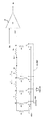
図1は,本実施の形態におけるメモリコントローラと,演算処理装置(CPUチップ)と,メインメモリとを有する情報処理装置の構成例を示す図である。図1の(A)には,演算処理部(CPUコア)12とメモリコントローラ20とを有する演算処理装置(CPUチップ)10と,メインメモリ30とを有する情報処理装置(コンピュータシステム)が示されている。演算処理部(CPUコア)12は,メモリコントローラ20に対してメモリアクセス要求を発行し,メモリコントローラ20はメモリアクセス要求に応答して,メインメモリ30に対して図示しないコマンドとアドレスとクロックCLKを送信する。一方,メインメモリ30は,読み出し要求の場合に,供給されたクロックCLKに基づいて生成したデータストローブ信号DQS(以下DQS信号)と,DQS信号の立ち上がりエッジと立ち下がりエッジに同期したデータ信号DQ(以下DQ信号)とを,メモリコントローラ20に返信する。メモリコントローラ20は,DQ信号受信回路21を有し,DQ信号受信回路21は,受信したDQS信号の位相に基づいてDQ信号を取り込む(ラッチする)。そして,メモリコントローラ20は取り込んだDQ信号を演算処理部(CPUコア)12に送信する。
FIG. 1 is a diagram illustrating a configuration example of an information processing apparatus having a memory controller, an arithmetic processing unit (CPU chip), and a main memory in the present embodiment. FIG. 1A shows an information processing apparatus (computer system) having an arithmetic processing unit (CPU chip) 10 having an arithmetic processing unit (CPU core) 12 and a
図1の(B)には,演算処理部(CPUコア)12を内蔵する演算処理装置(CPUチップ)10と,演算処理装置10とは異なるチップで構成されるメモリコントローラ20と,メインメモリ30とを有する情報処理装置が示されている。演算処理部(CPUコア)12と,メモリコントローラ20と,メインメモリ30とのメモリアクセスに関する動作は,図1の(A)と同様である。
FIG. 1B shows an arithmetic processing unit (CPU chip) 10 incorporating an arithmetic processing unit (CPU core) 12, a
DDR型のSDRAMは,DDR3以降の規格では,メモリコントローラ20はクロックCLKをメインメモリ30内の複数のメモリチップに対してシリアルに転送して送信する。その結果,各メモリチップから返信されるDQS信号の位相は,ばらばらであり一致していない。
In the DDR type SDRAM, in the standard after DDR3, the
そこで,メモリコントローラ20内のDQ信号受信回路21は,DQ信号をDQS信号の位相に基づいて取り込む(ラッチする)とともに,DQS信号の位相とメモリコントローラ内の内部クロックとの位相との位相差に基づいて,取り込んだDQ信号の位相を調整し,内部クロックの位相に基づいて全てのDQ信号を取り込む(ラッチする)。つまり,DQ信号受信回路21は,DQ信号をメインメモリ30からのDQS信号の位相タイミングからメモリコントローラ20や演算処理部12側のクロックの位相タイミングに乗り換える処理を行う。
Therefore, the DQ
[DQ信号受信回路の概略説明]
図2は,DQ信号受信回路の構成の一例を示す図である。DQ信号受信回路21は,メインメモリ30から送信される差動のデータストローブ信号DQS,DQSxを入力するDQS入力バッファ22と,メインメモリから送信される単相のデータ信号DQを入力するDQ入力バッファ23とを有する。これらの入力バッファ22,23については後で詳述する。
[Overview of DQ signal receiving circuit]
FIG. 2 is a diagram illustrating an example of the configuration of the DQ signal receiving circuit. The DQ
メインメモリ30は,DQS信号と,DQS信号の立ち上がりエッジと立ち下がりエッジに同期したDQ信号とをペアにして,メモリコントローラ20に送信する。このDQS信号は,メモリコントローラ20内の内部クロックI_CLKの位相とは非同期であり,さらに,DQS信号のメインメモリ30からメモリコントローラ20までの伝搬時間は予想できない。
The
したがって,メモリコントローラ20内のDQ信号受信回路21は,第1に,受信したDQS信号とDQ信号の位相は同期しているので,受信したDQS信号の立ち上がりエッジと立ち下がりエッジの位相に基づいて,DQ信号のHレベルまたはLレベルをラッチする。第2に,DQ信号受信回路21は,DQS信号の位相と内部クロックI_CLKの位相と非同期であるので,DQ信号の位相を調整して,DQS信号の位相から内部クロックI_CLKの位相に乗り換える位相調整を行う。
Accordingly, first, the DQ
図2のDQ信号受信回路21は,上記のDQ信号をDQS信号の両エッジのタイミングに基づいてラッチし,内部クロックI_CLKのタイミングに乗り換える位相調整を行う位相調整部24を有する。位相調整部24は,90°位相シフト回路29が入力バッファ22の出力の内部DQS信号dqsを90°位相シフトした信号dqs90の両エッジのタイミングで,入力したDQ信号をラッチするフリップフロップFF1,FF2を有する。さらに,位相調整部24は,90°位相シフトしたDQS信号dqs90を遅延して遅延DQS信号ddqsを生成する第3の可変遅延回路DL3と,フリップフロップFF1,FF2でラッチされたDQ信号dqeven,dqoddを遅延して遅延DQ信号ddqeven,ddqoddを生成する第1,第2の可変遅延回路DL1,DL2とを有する。これらの可変遅延回路DL1,DL2,DL3は,後述する位相比較部25が生成する可変遅延設定値CDに基づいて位相を進めたり遅らせたりする。
The DQ
さらに,DQ信号受信回路21は,DQS信号の位相と内部クロックI_CLKの位相とを比較して,位相調整部24に位相調整用の可変遅延設定値CDを生成する位相比較部25を有する。可変遅延設定値CDは,DQS信号と内部クロックI_CLKの位相差に対応して位相差をなくすようにする遅延量を示す値である。この可変遅延設定値CDは,第1,第2,第3の可変遅延回路DL1,DL2,DL3に供給される。それにより,DQS信号dqs90と,DQ信号dqeven,dqoddは,可変遅延設定値CDに対応する遅延時間だけ遅延される。
Further, the DQ
位相比較部25は,遅延DQS信号ddqsを微少な固定幅だけ遅延する遅延回路DL4と,遅延回路DL4の入力と出力ddqs(a),ddqs(b)を,ddqs信号の立ち上がりエッジタイミング信号IHの判定タイミング中にラッチイネーブル状態になり,内部クロックI_CLKの立ち下がりエッジに同期してラッチするラッチ回路26とを有する。つまり,立ち上がりエッジタイミング信号IHはラッチ回路26のインヒビット信号であり,IH=Lの間,ラッチ回路26は動作状態になる。
The
さらに,位相比較部25は,ラッチ回路26がラッチした位相情報1,2に基づいて,遅延DQS信号ddqsの立ち上がりエッジと内部クロックI_CLKの立ち下がりエッジとの間の位相差を判定する位相判定部27を有する。そして,位相比較部25は,位相判定部27の位相判定結果に基づいて,位相差をなくすように可変遅延回路DL3の遅延量を制御する可変遅延設定値CDを生成するとともに,検出した位相差に基づいて最適なエッジタイミング信号IHを生成する可変遅延制御部28を有する。
Further, the
可変遅延回路DL1.DL2により位相調整された遅延DQ信号ddqeven,ddqoddは,最後に内部クロックI_CLKのタイミングに基づいて,フリップフロップFF3,FF4でラッチされることで,DQ信号は,内部クロックI_CLKのタイミングに乗り換えることができる。 The delayed DQ signals ddqeven and ddqodd phase-adjusted by the variable delay circuit DL1.DL2 are finally latched by the flip-flops FF3 and FF4 based on the timing of the internal clock I_CLK. You can change to the timing.
図3は,DQ信号受信回路の動作を示すタイミングチャート図である。図3の例では,前提として,メインメモリ30が送信するDQS信号の周波数に対して,内部クロックI_CLKは4倍の周波数を有する。そして,前述したとおり,DQS信号の位相と内部クロックI_CLKの位相とは非同期である。
FIG. 3 is a timing chart showing the operation of the DQ signal receiving circuit. In the example of FIG. 3, as a premise, the internal clock I_CLK has a frequency four times the frequency of the DQS signal transmitted by the
まず,90°位相シフト回路29が,DQS入力バッファ22で入力されたDQS信号dqsを90°位相シフトして90°位相シフト信号dqs90を生成する。この90°位相シフト信号dqs90の立ち上がりエッジと立ち下がりエッジのタイミングで,フリップフロップFF1,FF2が,DQ入力バッファ23で入力したDQ信号をラッチし,DQ信号dqeven,dqoddを出力する。これにより,高速のDQ信号は,2分周された低速のDQ信号に変換される。
First, the 90 °
次に,位相比較部25の動作について説明する。図4は,位相比較部25と位相調整部24とによる動作のフローチャート図である。図5は,位相比較部25内の位相判定部27の動作を説明する図である。
Next, the operation of the
図4のフローチャート図に示されるとおり,位相比較部25の位相判定部27は,遅延DQS信号ddqsの立ち上がりエッジと,内部クロックI_CLKの立ち下がりエッジとの位相比較を行う(S1)。位相判定結果が進みの場合(S2の進み),可変遅延制御部28は可変遅延回路DL3の可変遅延設定値CDを+1して可変遅延回路DL3の遅延量を増加する(S3)。位相判定結果が遅れの場合(S2の遅れ),可変遅延制御部28は可変遅延回路DL3の可変遅延設定値CDを−1して可変遅延回路DL3の遅延量を減少する(S4)。
As shown in the flowchart of FIG. 4, the phase determination unit 27 of the
そして,上記の位相比較S1,位相判定S2,可変遅延設定値の調整S3,S4を,位相判定S2で一致になるまで繰り返す。位相判定S2で位相が一致したことが検出されれば,位相比較部25と位相調整部24とによる位相調整動作は終了する。可変遅延設定値CDは,第1,第2の可変遅延回路DL1,DL2にも供給され,その出力である遅延DQ信号ddqeven,ddqoddの位相は,内部クロックI_CLKの立ち下がりエッジの位相と一致する。
Then, the above phase comparison S1, phase determination S2, and variable delay set value adjustment S3, S4 are repeated until the phase determination S2 matches. If it is detected in the phase determination S2 that the phases match, the phase adjustment operation by the
図2,3に戻り,可変遅延回路DL3が90°位相シフトDQS信号dqs90を可変遅延設定値CDだけ遅延して遅延DQS信号ddqs(a)を出力し,更に,可変遅延回路DL4が遅延DQS信号ddqs(a)を固定遅延だけ遅延してもう一つの遅延DQS信号ddqs(b)を出力する。 2 and 3, the variable delay circuit DL3 delays the 90 ° phase shift DQS signal dqs90 by the variable delay setting value CD and outputs the delayed DQS signal ddqs (a), and the variable delay circuit DL4 further delays the DQS signal. ddqs (a) is delayed by a fixed delay, and another delayed DQS signal ddqs (b) is output.
図5の位相比較部25の位相判定部27の動作説明図に示されるとおり,ラッチ回路26は,立ち上がりエッジタイミング信号IHのLレベルの期間において,内部クロックI_CLKの立ち下がりエッジに同期して,2つの遅延DQS信号ddqs(a),ddqs(b)をラッチする。そして,位相判定部27がラッチ回路26がラッチした位相情報2,1に基づいて,遅延DQS信号ddqs(a),ddqs(b)が内部クロックI_CLKの立ち上がりエッジに対して位相が進んでいるか遅れているか一致しているかを検出する。
As shown in the operation explanatory diagram of the phase determination unit 27 of the
図5の位相比較真理値表に示されるように,ラッチ回路26がラッチした位相情報2,1が「11」の場合は,遅延DQS信号ddqs(a),ddqs(b)が内部クロックI_CLKの立ち上がりエッジに対して位相が進んでいることを示す。また,「01」の場合は一致していることを示し,「00」の場合は遅れていることを示す。ただし,「10」の場合は異常状態であり無視する。
As shown in the phase comparison truth table of FIG. 5, when the
なお,図5の内部クロックI_CLKは,簡単化のために,DQS信号の1/2の周期(2倍の周波数)で示している。そのため,立ち上がりエッジタイミング信号IHは,DQS信号と同じ周期であり,デューティ比は50%となっている。内部クロックI_CLKがDQS信号の1/4の周期(4倍の周波数)の場合は,立ち上がりエッジタイミング信号IHは,DQS信号と同じ周期であり,デューティ比は75%となり,1/4周期の期間のみLレベルになり,ラッチ回路26のラッチ動作は,4回に1回の内部クロックI_CLKの立ち下がりエッジに同期して行われる。
Note that the internal clock I_CLK in FIG. 5 is shown with a half period (double frequency) of the DQS signal for the sake of simplicity. Therefore, the rising edge timing signal IH has the same cycle as the DQS signal, and the duty ratio is 50%. When the internal clock I_CLK has a quarter period (four times the frequency) of the DQS signal, the rising edge timing signal IH has the same period as the DQS signal, the duty ratio is 75%, and a period of a quarter period Only L level, and the latch operation of the
図3は,上記の位相比較と位相調整が終了した状態でのタイミングチャートである。図3に示されるとおり,遅延DQS信号ddqs(a),ddqs(b)は,90°位相シフト信号dqs90から,可変遅延回路DL3の遅延量DL3だけ,DL3に固定遅延回路DL4を加えたDL3+DL4だけ,それぞれ遅延している。同様に,遅延DQ信号ddqeven,ddqoddは,フリップフロップFF1,FF2でラッチされたDQ信号dqeven,dqoddから,可変遅延回路DL1,DL1の遅延量それぞれ遅延している。これにより,遅延DQ信号ddqeven,ddqoddhaは,内部クロックI_CLKの立ち下がりエッジに位相同期する。 FIG. 3 is a timing chart in a state where the phase comparison and the phase adjustment are completed. As shown in FIG. 3, the delayed DQS signals ddqs (a) and ddqs (b) are obtained from the 90 ° phase shift signal dqs90 by the delay amount DL3 of the variable delay circuit DL3, and DL3 + obtained by adding the fixed delay circuit DL4 to DL3. Each DL4 is delayed. Similarly, the delayed DQ signals ddqeven and ddqodd are delayed from the DQ signals dqeven and dqodd latched by the flip-flops FF1 and FF2, respectively, by the delay amounts of the variable delay circuits DL1 and DL1. Thereby, the delayed DQ signals ddqeven and ddqoddha are phase-synchronized with the falling edge of the internal clock I_CLK.
そして,フリップフロップFF3,FF4が,内部クロックI_CLKの立ち下がりエッジに同期して,遅延DQ信号ddqeven,ddqoddをラッチする。フリップフロップFF3,FF4は,ラッチタイミング信号のタイミング期間中にイネーブルになり,4回に1回の内部クロックI_CLKの立ち下がりエッジに同期して遅延DQ信号ddqeven,ddqoddをラッチする。 The flip-flops FF3 and FF4 latch the delayed DQ signals ddqeven and ddqodd in synchronization with the falling edge of the internal clock I_CLK. The flip-flops FF3 and FF4 are enabled during the timing period of the latch timing signal, and latch the delayed DQ signals ddqeven and ddqodd in synchronization with the falling edge of the internal clock I_CLK once every four times.
[DQS信号のデューティ比の変動]
図6は,DQS信号のデューティ比の変動を説明する図である。DQS入力バッファ22は,メインメモリ30から送信されてきた差動のDQS信号DQS,DQSxを受信し,単相の内部DQS信号dqsを出力する。また,DQS入力バッファ22は,差動DQS信号DQS,DQSxの振幅電圧を,I/O電源VDDHから内部電源VDDにレベル変換する。
[DQS signal duty ratio fluctuation]
FIG. 6 is a diagram for explaining the variation of the duty ratio of the DQS signal. The
メインメモリ30は,DQS信号DQS,DQSxのデューティ比を50%にして送信する。しかし,DQS入力バッファ22が出力する内部DQS信号dqsは,温度変化や電源電圧VDDH/VDDの変動に起因して,その立ち上がり時間や立ち下がり時間が変動する。しかも,立ち上がり時間と立ち下がり時間の変動幅は必ずしも同じにならないため,内部DQS信号dqsのデューティ比が変動する。
The
図6には,特性変動の一例として,Hレベルの幅とLレベルの幅が等しくデューティ比が50%の内部DQS信号dqs_1と,立ち下がり時間が長くなりHレベルの幅がLレベルの幅より大きくなりデューティ比が50%を超える内部DQS信号dqs_2と,逆に,立ち下がり時間が短くなりHレベルの幅がLレベルの幅より小さくなり,デューティ比が50%より低くなる内部DQS信号dqs_3とが示されている。 In FIG. 6, as an example of characteristic variation, the internal DQS signal dqs_1 in which the width of the H level and the width of the L level are equal and the duty ratio is 50%, and the fall time becomes longer than the width of the L level. The internal DQS signal dqs_2 that increases and the duty ratio exceeds 50%, and conversely, the internal DQS signal dqs_3 that the fall time becomes shorter, the H level width becomes smaller than the L level width, and the duty ratio becomes lower than 50%. It is shown.
このような関係例は,実験などを通じて確認することができ,その確認を通じて,温度変化や電源電圧VDDH/VDDの変動とデューティ比の変動の関係を見出すことができる。いずれにしても,温度変化や電源電圧VDDH/VDDによる特性変動がデューティ比の変動に何らかの因果関係を有することが判明している。 Such a relationship example can be confirmed through experiments and the like, and through the confirmation, a relationship between a change in temperature, a variation in the power supply voltage VDDH / VDD, and a variation in the duty ratio can be found. In any case, it has been found that characteristic changes due to temperature changes and power supply voltages VDDH / VDD have some cause and effect on duty ratio fluctuations.
図7は,DQ入力バッファにおける基準電圧VREFの変動を説明する図である。DQ入力バッファ23は,メインメモリ30から送信されるDQ信号を,内部で生成した基準電圧VREFと比較して,HレベルまたはLレベルの内部DQ信号dqを出力する。図示されるように,入力DQ信号DQは電源VDDHの振幅を有するのに対して,基準電圧VREFはその振幅電圧VDDHの50%の電位に設定される。そのような基準電圧VREFに基づいて入力DQ信号DQのHレベルとLレベルの判定マージンを最大化することができる。
FIG. 7 is a diagram for explaining the variation of the reference voltage VREF in the DQ input buffer. The
一方,基準電圧VREFは,I/O電源VDDHを抵抗R1,R2で分割して生成される。その結果,I/O電源VDDHが変動することで,基準電圧VREFも変動する。したがって,前述してI/O電源VDDHの変動に起因して内部DQS信号dqsのデューティ比が変動するとともに,基準電圧VREFも変動する。これが,内部DQS信号dqsのデューティ比の変動と,基準電圧VREFの変動との間にある因果関係である。 On the other hand, the reference voltage VREF is generated by dividing the I / O power supply VDDH by resistors R1 and R2. As a result, when the I / O power supply VDDH varies, the reference voltage VREF also varies. Therefore, the duty ratio of the internal DQS signal dqs varies due to the variation of the I / O power supply VDDH as described above, and the reference voltage VREF also varies. This is a causal relationship between the fluctuation of the duty ratio of the internal DQS signal dqs and the fluctuation of the reference voltage VREF.
図8は,DQ入力バッファ23の回路の一例を示す図である。DQ入力バッファ23は,電源VDDHにソースが接続された1対のPMOSトランジスタP1,P2と,グランド電源VSSにNMOSトランジスタN3を介してソースが接続された1対のNMOSトランジスタN1,N2とを有する。そして,差動対のNMOSトランジスタN1,N2のゲートには,基準電圧VREFと入力するDQ信号DQがそれぞれ入力される。また,NMOSトランジスタN3のゲートには,バイアス電圧を入力し、入力するDQ信号DQのHレベルとLレベルを,基準電圧VREFと比較することで検出し,内部DQ信号dqを出力する。
FIG. 8 is a diagram illustrating an example of the circuit of the
図7に戻り,基準電圧VREFが入力DQ信号の振幅電圧VDDHの50%の電位の場合は,DQ入力バッファ23のHレベルとLレベルの判定マージンが最大化され,判定精度を最大化できる。一方,基準電圧VREF_Lのように低下すると,DQ入力バッファ23のLレベル判定マージンが小さくなり,誤判定の可能性が高くなる。逆に,基準電圧VREF_Hのように上昇すると,DQ入力バッファ23のHレベル判定マージンが小さくなり,誤判定の可能性が高くなる。
Returning to FIG. 7, when the reference voltage VREF is 50% of the amplitude voltage VDDH of the input DQ signal, the determination margin between the H level and the L level of the
[実施の形態のデューティ比検出と基準電圧の調整]
本実施の形態のメモリコントローラは,上記のDQ入力バッファによる誤判定を抑制するために,DQS信号dqsのデューティ比を測定して,検出したデューティ比の変動に応じて,DQ入力バッファの基準電圧VREFの電位を調整する。そこで,以下,本実施の形態におけるデューティ比検出回路と,検出したデューティ比に基づいて基準電圧を調整して生成する基準電圧生成回路について説明する。
[Duty ratio detection and reference voltage adjustment of embodiment]
The memory controller according to the present embodiment measures the duty ratio of the DQS signal dqs and suppresses the reference voltage of the DQ input buffer according to the detected fluctuation of the duty ratio in order to suppress erroneous determination by the DQ input buffer. Adjust the VREF potential. Therefore, hereinafter, a duty ratio detection circuit according to the present embodiment and a reference voltage generation circuit that adjusts and generates a reference voltage based on the detected duty ratio will be described.
図9は,本実施の形態におけるデューティ比検出回路を示す図である。デューティ比検出回路40は,内部DQS信号dqs90の立ち上がりエッジと内部クロックI_CLKの第1の基準エッジとの間の第1の位相差CD1を検出する立ち上がりエッジの位相差検出部24_UP,25_UPと,内部DQS信号dqs90の立ち下がりエッジと内部クロックI_CLKの第2の基準エッジとの間の第2の位相差CD2を検出する立ち下がりエッジの位相差検出部24_DN,25_DNと,第1の位相差CD1と第2の位相差CD2とからデューティ比を検出するデューティ比検出部42とを有する。デューティ比検出部42は,検出したデューティ比に基づいてDQ入力バッファ23内の基準電圧生成回路を制御する基準電圧制御信号VREF_CNを出力する。
FIG. 9 is a diagram showing a duty ratio detection circuit in the present embodiment. The duty
立ち上がりエッジの位相差検出部24_UP,25_UPは,図2で説明した構成と同等であり,立ち上がりエッジ用の位相調整部24_UPと,立ち上がりエッジ用の位相比較部25_UPとを有する。なお,DQ信号を遅延する可変遅延回路DL1,DL2に対する可変遅延設定値は,図2に示したように,専用の位相調整部24と位相比較部25により生成される。
The rising edge phase difference detection units 24_UP and 25_UP have the same configuration as described in FIG. 2, and include a rising edge phase adjustment unit 24_UP and a rising edge phase comparison unit 25_UP. Note that the variable delay setting values for the variable delay circuits DL1 and DL2 for delaying the DQ signal are generated by the dedicated
立ち上がりエッジ用位相調整部24_UPは,内部DQS信号dqs90を遅延する可変遅延回路DL3_UPを有する。 The rising edge phase adjustment unit 24_UP includes a variable delay circuit DL3_UP that delays the internal DQS signal dqs90.
また,立ち上がりエッジ用比較部25_UPは,可変遅延回路DL3_UPが遅延して出力する第1の遅延DQS信号ddqs(a)を固定値だけ遅延して第2の遅延DQS信号ddqs(b)を出力する固定遅延回路DL4_UPと,第1,第2の遅延DQS信号ddqs(a),ddqs(b)を,ddqs信号の立ち上がりエッジタイミング信号IH1の判定タイミング中にラッチイネーブル状態になり,内部クロックI_CLKの第1の立ち下がりエッジに同期してラッチするラッチ回路26_UPとを有する。 The rising edge comparator 25_UP delays the first delayed DQS signal ddqs (a) output by the variable delay circuit DL3_UP with a fixed value and outputs the second delayed DQS signal ddqs (b). The fixed delay circuit DL4_UP and the first and second delayed DQS signals ddqs (a) and ddqs (b) are latch-enabled during the determination timing of the rising edge timing signal IH1 of the ddqs signal, and the internal clock I_CLK And a latch circuit 26_UP that latches in synchronization with the falling edge of one.
さらに,位相比較部25_UPは,ラッチ回路26_UPがラッチした位相情報1,2に基づいて,遅延DQS信号ddqsの立ち上がりエッジと内部クロックI_CLKの第1の立ち下がりエッジとの間の位相差を判定する位相判定部27_UPを有する。
Further, the phase comparator 25_UP determines the phase difference between the rising edge of the delayed DQS signal ddqs and the first falling edge of the internal clock I_CLK based on the
そして,位相比較部25_UPは,位相判定部27_UPの位相判定結果に基づいて,位相差をなくすように可変遅延回路DL3_UPの遅延量を制御する可変遅延設定値CD1を生成するとともに,検出した位相差に基づいて最適な立ち上がりエッジタイミング信号IHを生成する可変遅延制御部28_UPを有する。 Then, the phase comparison unit 25_UP generates a variable delay setting value CD1 that controls the delay amount of the variable delay circuit DL3_UP so as to eliminate the phase difference based on the phase determination result of the phase determination unit 27_UP and detects the detected phase difference. Is provided with a variable delay control unit 28_UP that generates an optimum rising edge timing signal IH.
立ち上がりエッジの位相差検出部24_UP,25_UPの位相比較と位相調整の動作は,図2と同様である。したがって,可変遅延設定値CD1による可変遅延回路DL3_UPの遅延量が,DQS信号dqs90の立ち上がりエッジと内部クロックI_CLKの基準立ち下がりエッジとの位相差になる。 The phase comparison and phase adjustment operations of the rising edge phase difference detectors 24_UP and 25_UP are the same as those in FIG. Therefore, the delay amount of the variable delay circuit DL3_UP by the variable delay setting value CD1 is a phase difference between the rising edge of the DQS signal dqs90 and the reference falling edge of the internal clock I_CLK.
一方,立ち下がりエッジの位相差検出部24_DN,25_DNは,上記の立ち上がりエッジの位相差検出部24_UP,25_UPと同様であり,立ち下がりエッジ用の位相調整部24_DNと,立ち下がりエッジ用の位相比較部25_DNとを有する。これらの構成も,立ち上がりエッジ用の位相調整部24_UPと,立ち上がりエッジ用の位相比較部25_UPと同様である。 On the other hand, the falling edge phase difference detection units 24_DN and 25_DN are the same as the rising edge phase difference detection units 24_UP and 25_UP described above, and the falling edge phase adjustment unit 24_DN is compared with the falling edge phase comparison. Part 25_DN. These configurations are also the same as the phase adjustment unit 24_UP for the rising edge and the phase comparison unit 25_UP for the rising edge.
但し,異なる点としては,立ち下がりエッジの位相差検出部24_DN,25_DNは,内部DQS信号dqs90の立ち下がりエッジと,内部クロックI_CLKの第2の立ち下がりエッジとの位相差を比較するので,ラッチ回路26_DNは,ddqs信号の立ち下がりエッジタイミング信号IH2の判定タイミング中にラッチイネーブル状態になり,内部クロックI_CLKの第2の立ち下がりエッジに同期して第3,第4の遅延DQS信号ddqs(c),ddqs(d)を,ラッチする。 However, the difference is that the falling edge phase difference detectors 24_DN and 25_DN compare the phase difference between the falling edge of the internal DQS signal dqs90 and the second falling edge of the internal clock I_CLK. The circuit 26_DN enters the latch enable state during the determination timing of the falling edge timing signal IH2 of the ddqs signal, and synchronizes with the second falling edge of the internal clock I_CLK, and the third and fourth delayed DQS signals ddqs (c ) And ddqs (d) are latched.
さらに異なる点としては,位相判定部27_DNは,図5と異なり,位相情報4,3が「00」の場合に内部DQS信号ddqs(c),ddqs(d)が内部クロックI_CLKの第2の立ち下がりエッジより位相が進んでいる,「10」の場合に一致している,「11」の場合に遅れているとそれぞれ判定する。
Further, the phase determination unit 27_DN is different from FIG. 5 in that, when the
したがって,可変遅延設定値CD2による可変遅延回路DL3_DNの遅延量が,DQS信号dqs90の立ち下がりエッジと内部クロックI_CLKの基準立ち下がりエッジとの位相差になる。 Therefore, the delay amount of the variable delay circuit DL3_DN by the variable delay setting value CD2 is the phase difference between the falling edge of the DQS signal dqs90 and the reference falling edge of the internal clock I_CLK.
図10は,デューティ比検出回路42の動作を示す図である。図10(A)は,デューティ比が50%の場合の位相が一致している状態のタイミングチャートであり,図10(B)は,デューティ比が50%でない場合(60%)の位相が一致している状態のタイミングチャートであり,図10(C)は,デューティ比の50%からのずれ量を示す。 FIG. 10 is a diagram illustrating the operation of the duty ratio detection circuit 42. FIG. 10A is a timing chart in a state where the phases match when the duty ratio is 50%, and FIG. 10B shows the same phase when the duty ratio is not 50% (60%). FIG. 10C shows the amount of deviation from 50% of the duty ratio.
図10(A)に示されるように,立ち上がりエッジ用比較部25_UP内のラッチ回路26_UPは,ddqs信号の立ち上がりエッジタイミング信号IH1がLレベルの間において,内部クロックI_CLKの第1の立ち下がりエッジDE1に同期して,遅延DQS信号ddqs(a),ddqs(b)をラッチし,そのラッチ出力である位相情報2,1が「01」(位相一致)となっている。この時,遅延DQS信号ddqs(a)の立ち上がりエッジと内部クロックI_CLKの基準立ち下がりエッジDE1とは位相同期している。したがって,可変遅延回路DL3_UPの遅延量は,DQS信号dqs90の立ち上がりエッジと内部クロックI_CLKの基準立ち下がりエッジDE1との位相差(DL3_UP)と等しい。
As shown in FIG. 10 (A), the latch circuit 26_UP in the rising edge comparator 25_UP has a first falling edge DE1 of the internal clock I_CLK while the rising edge timing signal IH1 of the ddqs signal is at the L level. The delayed DQS signals ddqs (a) and ddqs (b) are latched in synchronism with each other, and the
一方,立ち下がりエッジ用比較部25_DN内のラッチ回路26_DNは,ddqs信号の立ち下がりエッジタイミング信号IH2がLレベルの間において,内部クロックI_CLKの第2の立ち下がりエッジDE2に同期して,遅延DQS信号ddqs(c),ddqs(d)をラッチし,そのラッチ出力である位相情報4,3が「10」(位相一致)となっている。この時,遅延DQS信号ddqs(c)の立ち下がりエッジと内部クロックI_CLKの基準立ち下がりエッジDE2とは位相同期している。したがって,可変遅延回路DL3_DNの遅延量は,DQS信号dqs90の立ち下がりエッジと内部クロックI_CLKの基準立ち下がりエッジDE2との位相差(DL3_DN)と等しい。
On the other hand, the latch circuit 26_DN in the falling edge comparison unit 25_DN has a delay DQS in synchronization with the second falling edge DE2 of the internal clock I_CLK while the falling edge timing signal IH2 of the ddqs signal is at the L level. The signals ddqs (c) and ddqs (d) are latched, and the
そして,上記の2つの位相差DL3_UPとDL3_DNは等しい。すなわち,図10(A)は,図5と同様に,内部クロックI_CLKがDQS信号の2倍の周波数の例であるので,内部クロックI_CLKの第1の立ち下がりエッジDE1と第2の立ち下がりエッジDE2の位相差は,デューティ比50%の場合のDQS信号の立ち上がりエッジと立ち下がりエッジの位相差と等しい。そこで,図10(C)に示されるように,デューティ比が50%の場合は,2つの遅延量DL3_UPとDL3_DNが等しく,その差分はゼロになる。 The above two phase differences DL3_UP and DL3_DN are equal. That is, FIG. 10A shows an example in which the internal clock I_CLK has a frequency twice that of the DQS signal, as in FIG. 5, and therefore the first falling edge DE1 and the second falling edge of the internal clock I_CLK. The phase difference of DE2 is equal to the phase difference between the rising edge and falling edge of the DQS signal when the duty ratio is 50%. Therefore, as shown in FIG. 10C, when the duty ratio is 50%, the two delay amounts DL3_UP and DL3_DN are equal, and the difference between them is zero.
次に,図10(B)の場合も同様に,立ち上がりエッジ用比較部25_UP内のラッチ回路26_UPは,ddqs信号の立ち上がりエッジタイミング信号IH1がLレベルの間において,内部クロックI_CLKの第1の立ち下がりエッジDE1に同期して,遅延DQS信号ddqs(a),ddqs(b)をラッチし,そのラッチ出力である位相情報2,1が「01」(位相一致)となっている。この時,遅延DQS信号ddqs(a)の立ち上がりエッジと内部クロックI_CLKの基準立ち下がりエッジDE1とは位相同期している。したがって,可変遅延回路DL3_UPの遅延量は,DQS信号dqs90の立ち上がりエッジと内部クロックI_CLKの基準立ち下がりエッジDE1との位相差(DL3_UP)と等しい。
Similarly, in the case of FIG. 10B as well, the latch circuit 26_UP in the rising edge comparison unit 25_UP causes the first rising edge of the internal clock I_CLK while the rising edge timing signal IH1 of the ddqs signal is at the L level. In synchronism with the falling edge DE1, the delayed DQS signals ddqs (a) and ddqs (b) are latched, and the
一方,立ち下がりエッジ用比較部25_DN内のラッチ回路26_DNは,ddqs信号の立ち下がりエッジタイミング信号IH2がLレベルの間において,内部クロックI_CLKの第2の立ち下がりエッジDE2に同期して,遅延DQS信号ddqs(c),ddqs(d)をラッチし,そのラッチ出力である位相情報4,3が「10」(位相一致)となっている。この時,遅延DQS信号ddqs(c)の立ち下がりエッジと内部クロックI_CLKの基準立ち下がりエッジDE2とは位相同期している。したがって,可変遅延回路DL3_DNの遅延量は,DQS信号dqs90の立ち下がりエッジと内部クロックI_CLKの基準立ち下がりエッジDE2との位相差(DL3_DN)と等しい。
On the other hand, the latch circuit 26_DN in the falling edge comparison unit 25_DN has a delay DQS in synchronization with the second falling edge DE2 of the internal clock I_CLK while the falling edge timing signal IH2 of the ddqs signal is at the L level. The signals ddqs (c) and ddqs (d) are latched, and the
但し,上記の2つの位相差DL3_UPとDL3_DNは等しくなく,DL3_UP>DL3_DNの関係になっている。したがって,図10(C)に示されるように,デューティ比が50%を超える場合は,2つの遅延量の差分DL3_UP−DL3_DN>0となる。逆に,デューティ比が50%より小さい場合は,2つの遅延量の差分はDL3_UP−DL3_DN<0となる。 However, the above two phase differences DL3_UP and DL3_DN are not equal, and the relationship is DL3_UP> DL3_DN. Therefore, as shown in FIG. 10C, when the duty ratio exceeds 50%, the difference DL3_UP−DL3_DN> 0 between the two delay amounts. Conversely, when the duty ratio is smaller than 50%, the difference between the two delay amounts is DL3_UP−DL3_DN <0.
このように,DQS信号のデューティ比は,DQS信号の立ち上がりエッジと内部クロックI_CLKの第1の基準エッジDE1との第1の位相差と,DQS信号の立ち下がりエッジと内部クロックI_CLKの第2の基準エッジDE2との第2の位相差との差に基づいて,デューティ比50%からどの程度ずれているかを検出することができる。これは,内部クロックI_CLKの基準エッジは一定の周期であることが前提である。 As described above, the duty ratio of the DQS signal includes the first phase difference between the rising edge of the DQS signal and the first reference edge DE1 of the internal clock I_CLK, the second phase of the DQS signal and the second clock of the internal clock I_CLK. Based on the difference from the reference phase DE2 and the second phase difference, it is possible to detect how much the duty ratio deviates from 50%. This is based on the premise that the reference edge of the internal clock I_CLK has a constant period.
図11は,デューティ比検出部42の動作を説明する図である。デューティ比を次のように定義する。
Duty={(DQS信号のH幅)/(DQS信号の周期)}*100(%)
そして,可変遅延設定値CD1−可変遅延設定値CD2=Xと定義すると,デューティ比は次のとおりである。
Duty=50+aX (1)
ここで,係数aは,
a={(可変遅延回路DL3_UP,DL3_DNの単位遅延量)/(DQS信号の周期)}*100
である。
FIG. 11 is a diagram for explaining the operation of the duty ratio detection unit 42. The duty ratio is defined as follows.
Duty = {(DQS signal H width) / (DQS signal cycle)} * 100 (%)
When the variable delay set value CD1−variable delay set value CD2 = X is defined, the duty ratio is as follows.
Duty = 50 + aX (1)
Here, the coefficient a is
a = {(unit delay amount of variable delay circuits DL3_UP, DL3_DN) / (cycle of DQS signal)} * 100
It is.
ここで,可変遅延回路DL3_UP,DL3_DNは,複数の単位遅延要素を直列に接続し,可変遅延設定値CD1,CD2により,その単位遅延要素の数が可変設定されるものとする。そして,単位遅延要素の遅延時間が,上記の単位遅延量に対応する。つまり,上記の式(1)は,可変遅延設定値CD1,CD2の差分Xに,単位遅延量のDQS信号の周期に対する比率aを乗算して,50%に加算することで,デューティ比が算出できることを示している。 Here, in the variable delay circuits DL3_UP and DL3_DN, a plurality of unit delay elements are connected in series, and the number of unit delay elements is variably set by the variable delay setting values CD1 and CD2. The delay time of the unit delay element corresponds to the unit delay amount. In other words, the above equation (1) calculates the duty ratio by multiplying the difference X between the variable delay setting values CD1 and CD2 by the ratio a of the unit delay amount to the period of the DQS signal and adding it to 50%. It shows what you can do.
図11には,X=3,DQS信号の周期=1000ps,可変遅延回路の単位遅延量=20psの例が示されている。この場合,係数aは,
a=20/1000×100=2
となり,式(1)によりデューティ比dutyは次の通りになる。
duty=50+aX=50+2×3=56%
また,図11には,可変遅延設定値CD1,CD2の差分Xと,デューティ比との関係を示す図表が示されている。これによれば,X>0の場合はDQS信号のH幅が広く,デューティ比は50%を越え,X=0の場合はDQSのH幅とL幅は等しく,デューティ比は50%となり,X<0の場合はDQSのL幅が広く,デューティ比は50%より低くなる。
FIG. 11 shows an example in which X = 3, the period of the DQS signal = 1000 ps, and the unit delay amount of the variable delay circuit = 20 ps. In this case, the coefficient a is
a = 20/1000 × 100 = 2
Thus, the duty ratio duty is given by the following equation (1).
duty = 50 + aX = 50 + 2 × 3 = 56%
FIG. 11 is a chart showing the relationship between the difference X between the variable delay set values CD1 and CD2 and the duty ratio. According to this, when X> 0, the H width of the DQS signal is wide and the duty ratio exceeds 50%. When X = 0, the H width and L width of the DQS are equal and the duty ratio is 50%. When X <0, the DQS L width is wide and the duty ratio is lower than 50%.
図12は,DQ入力バッファ内の基準電圧生成回路の一例を示す図である。DQ入力バッファ23は,基準電圧VREFを生成する基準電圧生成回路23_VREFを有する。基準電圧生成回路23_VREFは,デューティ比検出部42から供給される基準電圧制御信号VREF_CNに基づいて,基準電圧VREFの電位を調整する。
FIG. 12 is a diagram illustrating an example of a reference voltage generation circuit in the DQ input buffer. The
図12に示した一例としての基準電圧生成回路23_VREFは,抵抗2Rと,抵抗Rのラダー回路であり,ノードN0〜Nnにそれぞれ接続された抵抗2Rは,スイッチS0〜Snを介して,I/O電源VDDHまたはグランド電圧VSSのいずれかに接続される。基準電圧制御信号VREF_CNは,スイッチS0〜Snのいずれか1つをI/O電源VDDHに接続し,それ以外の全てをグランド電源VSSに接続する。
The reference voltage generating circuit 23_VREF as an example shown in FIG. 12 is a
この回路によれば,ノードN2の抵抗2RだけがスイッチS2を介してI/O電源VDDHに接続されている。そこで,ノードN0から左側の抵抗値は2Rであり,ノードN1から左側の抵抗値も2Rであり,ノードN2から左側の抵抗値も2Rである。一方,ノードNnから右側の抵抗値は2Rであり,同様にノードNn-1から右側の抵抗値も2Rであり,以下同様に,ノードNn-2〜N2から右側の抵抗値も全て2Rである。
According to this circuit, only the
したがって,基準電圧制御信号VREF_CNによりI/O電源VDDHに接続されているノードN2の左右の電圧は共に2Rとなる。したがって,ノードN2とグランドVSSとの間は並列な2つの抵抗2Rが設けられ,ノードN2とI/O電源VDDHとの間は1つの抵抗2Rが設けられるので,ノードN2の電圧は,I/O電源VDDHを2RとRとで抵抗分圧されてVDDH/3となる。
Therefore, the left and right voltages of the node N2 connected to the I / O power supply VDDH by the reference voltage control signal VREF_CN are both 2R. Therefore, two
さらに,ノードN2の左右に流れる電流i2,i3は,ノードN2の左右のグランドVSSまでの抵抗値が2Rと等しいので,i2=i3となり,I/O電源VDDHからノードN2に流れる電流i1は,i1=i2+i3となる。さらに,右隣のノードN3でも電流が1/2ずつ分岐していく。 Furthermore, the currents i2 and i3 flowing to the left and right of the node N2 have a resistance value equal to 2R to the left and right ground VSS of the node N2, so i2 = i3, and the current i1 flowing from the I / O power supply VDDH to the node N2 is i1 = i2 + i3. Furthermore, the current also divides by 1/2 at the node N3 on the right.
よって,スイッチSk(k=0〜n)の抵抗2Rに,1/2,1/4,1/(2L)と重みが付くので,ノードSnの基準電圧VREFは,次のようになる。
VREF=(1/2n-k)*(VDDH/3) (2)
したがって,基準電圧制御信号VREF_CNによりいずれかのスイッチSkをI/O電源VDDH側に接続することで,ノードSnに生成される基準電圧VREFを上記の式(2)のように可変制御することができる。
Therefore, since the
VREF = (1/2 nk ) * (VDDH / 3) (2)
Therefore, the reference voltage VREF generated at the node Sn can be variably controlled as in the above equation (2) by connecting any one of the switches Sk to the I / O power supply VDDH side by the reference voltage control signal VREF_CN. it can.
図13は,本実施の形態におけるメモリコントローラによる基準電圧制御プロセスのフローチャート図である。メモリコントローラは,リード動作制御を行いながら,受信するデータストローブ信号DQSのデューティ比を測定する(S10)。デューティ比測定回路40は,基準となる内部クロックI_CLKの第1,第2の基準エッジと,DQS信号の立ち上がりエッジ及び立ち下がりエッジとの位相差をゼロにするように可変遅延回路DL3_UP,DL3_DNの可変遅延設定値CD1,CD2を制御する。そして,デューティ比測定回路40は,可変遅延設定値CD1,CD2の差分がゼロか否か検出し(S12),ゼロの場合は(S12のYES),DQS信号のデューティ比が50%であるので,設定済みの基準電圧VREFの使用を継続する(S13)。一方,ゼロでない場合は(S12のNO),DQS信号のデューティ比が50%よりずれていることを意味する。そこで,正規のリード動作中であれば(S14のYES),設定済みの基準電圧VREFの使用を継続し,正規のリード動作中でない間に(S14のNO),可変遅延設定値CD1,CD2の差分に応じて,基準電圧VREFを上昇設定または下降設定する(S16)。
FIG. 13 is a flowchart of the reference voltage control process by the memory controller in the present embodiment. The memory controller measures the duty ratio of the received data strobe signal DQS while performing the read operation control (S10). The duty
図14は,本実施の形態における基準電圧制御プロセスを説明する図である。デューティ比測定回路40が測定したDQS信号のHレベルの幅とLレベルの幅が等しく,差分がゼロの場合,つまり,可変遅延設定値CD1とCD2の差分がゼロの場合(CD1-CD2=0),DQ信号に対する基準電圧VREFは,適切な電位に設定されている。
FIG. 14 is a diagram illustrating a reference voltage control process in the present embodiment. When the H level width and L level width of the DQS signal measured by the duty
一方,DQS信号のHレベルの幅がLレベルの幅より長く,差分がプラスの場合,つまり,可変遅延設定値CD1とCD2の差分がプラスの場合(CD1-CD2>0),DQ信号に対する基準電圧VREFは,適切な電位より低下しているので,基準電圧制御信号VREF_CNを変更して,基準電圧VREFを上昇するように調整する。その結果,基準電圧VREFが受信するデータ信号DQの振幅電圧の中央値に近づくように調整される。 On the other hand, if the H level width of the DQS signal is longer than the L level width and the difference is positive, that is, if the difference between the variable delay setting values CD1 and CD2 is positive (CD1-CD2> 0), the reference for the DQ signal Since the voltage VREF is lower than an appropriate potential, the reference voltage control signal VREF_CN is changed and adjusted so as to increase the reference voltage VREF. As a result, the reference voltage VREF is adjusted so as to approach the median value of the amplitude voltage of the received data signal DQ.
さらに,DQS信号のHレベルの幅がLレベルの幅より短く,差分がマイナスの場合,つまり,可変遅延設定値CD1とCD2の差分がマイナスの場合(CD1-CD2<0),DQ信号に対する基準電圧VREFは,適切な電位より上昇しているので,基準電圧制御信号VREF_CNを変更して,基準電圧VREFを下降するように調整する。その結果,基準電圧VREFが受信するデータ信号DQの振幅電圧の中央値に近づくように調整される。 Furthermore, if the DQS signal H level width is shorter than the L level width and the difference is negative, that is, if the difference between the variable delay setting values CD1 and CD2 is negative (CD1-CD2 <0), the reference for the DQ signal Since the voltage VREF has risen from an appropriate potential, the reference voltage control signal VREF_CN is changed and adjusted so as to lower the reference voltage VREF. As a result, the reference voltage VREF is adjusted so as to approach the median value of the amplitude voltage of the received data signal DQ.
メモリコントローラは,図2に示した位相調整制御を,正規のリード動作やライト動作が開始される前のトレーニング期間に,擬似的なリード動作を実施して,受信するDQ信号の位相調整を行う。そこで,本実施の形態の基準電圧制御プロセスを,上記のトレーニング期間で実施してもよい。 The memory controller performs the phase adjustment of the received DQ signal by performing a pseudo read operation in the training period before the normal read operation or write operation is started in the phase adjustment control shown in FIG. . Therefore, the reference voltage control process of the present embodiment may be performed during the training period.
以上,本実施の形態によれば,DQS信号のデューティ比と基準電圧VREFとの間の相互関係を利用して,DQS信号のデューティ比を測定し,その検出したデューティ比に応じて基準電圧VREFを可変制御し,基準電圧VREFがDS信号の振幅電圧の中央値に近づくように調整するようにしたので,DQ信号のHレベルとLレベルの判定マージンを最大化でき,誤判定を抑制することができる。 As described above, according to the present embodiment, the DQS signal duty ratio is measured using the correlation between the DQS signal duty ratio and the reference voltage VREF, and the reference voltage VREF is determined according to the detected duty ratio. Since the reference voltage VREF is adjusted so that it approaches the median value of the amplitude voltage of the DS signal, the judgment margin for the H level and L level of the DQ signal can be maximized, and erroneous judgments can be suppressed. Can do.
40:デューティ比検出回路
24_UP,25_UP:DQS信号の立ち上がりエッジの位相差検出部
24_DN,25_DN:DQS信号の立ち上がりエッジの位相差検出部
42:デューティ比検出部,基準電圧設定部
22:DQS入力バッファ
23:DQ入力バッファ
VRE_CN:基準電圧制御信号
40: Duty ratio detection circuit
24_UP, 25_UP: DQS signal rising edge phase difference detector
24_DN, 25_DN: DQS signal rising edge phase difference detection unit 42: duty ratio detection unit, reference voltage setting unit 22: DQS input buffer 23: DQ input buffer
VRE_CN: Reference voltage control signal
Claims (7)
受信するデータストローブ信号を入力する第2の入力バッファと,
前記第2の入力バッファが出力する内部データストローブ信号の立ち上がりエッジと立ち下がりエッジの位相に基づいて,前記第1の入力バッファが出力するデータ信号を取り込むデータラッチ回路と,
前記内部データストローブ信号のデューティ比を検出するデューティ比検出回路と,
前記デューティ比検出回路が検出したデューティ比に基づいて,前記基準電圧を調整する基準電圧生成回路とを有するメモリコントローラ。 A first input buffer for determining a received data signal based on a reference voltage;
A second input buffer for inputting a data strobe signal to be received;
A data latch circuit that captures a data signal output from the first input buffer based on a phase of a rising edge and a falling edge of an internal data strobe signal output from the second input buffer;
A duty ratio detection circuit for detecting a duty ratio of the internal data strobe signal;
A memory controller comprising: a reference voltage generation circuit that adjusts the reference voltage based on the duty ratio detected by the duty ratio detection circuit.
前記デューティ比検出回路は,前記内部データストローブ信号の立ち上がりエッジとクロックの第1の基準エッジとの間の第1の位相差を検出する第1の位相差検出部と,前記内部データストローブ信号の立ち下がりエッジと前記クロックの第2の基準エッジとの間の第2の位相差を検出する第2の位相差検出部と,前記第1の位相差と前記第2の位相差とから前記デューティ比を検出するデューティ比検出部とを有するメモリコントローラ。 In claim 1,
The duty ratio detection circuit includes a first phase difference detection unit that detects a first phase difference between a rising edge of the internal data strobe signal and a first reference edge of a clock; A second phase difference detecting unit for detecting a second phase difference between a falling edge and a second reference edge of the clock; and the duty ratio based on the first phase difference and the second phase difference. A memory controller having a duty ratio detection unit for detecting a ratio.
前記第1の位相差検出部は,前記内部データストローブ信号を第1の可変遅延設定値に基づく遅延量だけ遅延する第1の可変遅延回路と,前記第1の可変遅延回路で遅延した第1の遅延データストローブ信号の立ち上がりエッジと前記クロックの第1の基準エッジとの間の第3の位相差を検出し前記第3の位相差を小さくするよう前記第1の可変遅延設定値を生成する第1の位相比較部とを有し,
前記第2の位相差検出部は,前記内部データストローブ信号を第2の可変遅延設定値に基づく遅延量だけ遅延する第2の可変遅延回路と,前記第2の可変遅延回路で遅延した第2の遅延データストローブ信号の立ち下がりエッジと前記クロックの第2の基準エッジとの間の第4の位相差を検出し前記第4の位相差を小さくするよう前記第2の可変遅延設定値を生成する第2の位相比較部とを有し,
前記デューティ比検出部は,前記第1の可変遅延設定値と前記第2の可変遅延設定値との差分に基づいて,前記デューティ比を算出するメモリコントローラ。 In claim 2,
The first phase difference detection unit includes a first variable delay circuit that delays the internal data strobe signal by a delay amount based on a first variable delay setting value, and a first delay that is delayed by the first variable delay circuit. And detecting the third phase difference between the rising edge of the delayed data strobe signal and the first reference edge of the clock, and generating the first variable delay setting value so as to reduce the third phase difference. A first phase comparison unit;
The second phase difference detection unit includes a second variable delay circuit that delays the internal data strobe signal by a delay amount based on a second variable delay setting value, and a second variable delay circuit that is delayed by the second variable delay circuit. Detecting a fourth phase difference between the falling edge of the delayed data strobe signal and the second reference edge of the clock, and generating the second variable delay setting value so as to reduce the fourth phase difference. A second phase comparator that
The duty ratio detection unit is a memory controller that calculates the duty ratio based on a difference between the first variable delay setting value and the second variable delay setting value.
前記第1の位相比較部は,前記クロックから生成される第1の位相判定タイミング信号の位相判定タイミング期間中の前記クロックのエッジを,前記クロックの第1の基準エッジとして使用し,
前記第2の位相比較部は,前記第1の位相判定タイミング信号を反転した第2の位相判定タイミング信号の位相判定タイミング中の前記クロックのエッジを,前記クロックの第2の基準エッジとして使用するメモリコントローラ。 In claim 3,
The first phase comparison unit uses an edge of the clock during a phase determination timing period of a first phase determination timing signal generated from the clock as a first reference edge of the clock;
The second phase comparison unit uses the edge of the clock in the phase determination timing of the second phase determination timing signal obtained by inverting the first phase determination timing signal as the second reference edge of the clock. Memory controller.
前記基準電圧生成回路は,前記デューティ比が50%より高い場合に,前記基準電圧を前記デューティ比が50%の場合の基準電圧より上昇させ,前記デューティ比が50%より低い場合に,前記基準電圧を前記デューティ比が50%の場合の基準電圧より下降させるメモリコントローラ。 In claim 1 or 2,
The reference voltage generation circuit raises the reference voltage above the reference voltage when the duty ratio is 50% when the duty ratio is higher than 50%, and when the duty ratio is lower than 50%, A memory controller for lowering a voltage from a reference voltage when the duty ratio is 50%.
メモリアクセスに応答してデータ信号と前記データ信号に同期したデータストローブ信号を出力するメモリと,
前記メモリアクセス要求に応答して,前記メモリへのアクセス制御を行うメモリコントローラとを有し,
前記メモリコントローラは,
前記メモリから受信する前記データ信号を基準電圧に基づいて判定する第1の入力バッファと,
前記メモリから受信する前記データストローブ信号を入力する第2の入力バッファと,
前記第2の入力バッファが出力する内部データストローブ信号の立ち上がりエッジと立ち下がりエッジの位相に基づいて,前記第1の入力バッファが出力するデータ信号を取り込むデータラッチ回路と,
前記内部データストローブ信号のデューティ比を検出するデューティ比検出回路と,
前記デューティ比検出回路が検出したデューティ比に基づいて,前記基準電圧を調整する基準電圧生成回路とを有する情報処理装置。 An arithmetic processing unit that requests memory access;
A memory for outputting a data signal and a data strobe signal synchronized with the data signal in response to a memory access;
A memory controller that controls access to the memory in response to the memory access request;
The memory controller is
A first input buffer for determining the data signal received from the memory based on a reference voltage;
A second input buffer for inputting the data strobe signal received from the memory;
A data latch circuit that captures a data signal output from the first input buffer based on a phase of a rising edge and a falling edge of an internal data strobe signal output from the second input buffer;
A duty ratio detection circuit for detecting a duty ratio of the internal data strobe signal;
An information processing apparatus comprising: a reference voltage generation circuit that adjusts the reference voltage based on the duty ratio detected by the duty ratio detection circuit.
受信するデータストローブ信号を入力する第2の入力バッファと,
前記第2の入力バッファが出力する内部データストローブ信号の立ち上がりエッジと立ち下がりエッジの位相に基づいて,前記第1の入力バッファが出力するデータ信号を取り込むデータラッチ回路とを有するメモリコントローラにおける基準電圧調整方法であって,
デューティ比検出回路が,前記内部データストローブ信号のデューティ比を検出する工程と,
基準電圧生成回路が,前記検出したデューティ比に基づいて,前記基準電圧を調整する工程を有する基準電圧調整方法。 A first input buffer for determining a received data signal based on a reference voltage;
A second input buffer for inputting a data strobe signal to be received;
A reference voltage in a memory controller having a data latch circuit that captures the data signal output from the first input buffer based on the phase of the rising edge and falling edge of the internal data strobe signal output from the second input buffer An adjustment method,
A duty ratio detection circuit detecting a duty ratio of the internal data strobe signal;
A reference voltage adjusting method , wherein a reference voltage generating circuit includes a step of adjusting the reference voltage based on the detected duty ratio.
Priority Applications (2)
| Application Number | Priority Date | Filing Date | Title |
|---|---|---|---|
| JP2014011872A JP6209978B2 (en) | 2014-01-24 | 2014-01-24 | Memory controller, information processing apparatus and reference voltage adjusting method |
| US14/599,585 US9747972B2 (en) | 2014-01-24 | 2015-01-19 | Memory controller, information processing device, and reference voltage adjustment method |
Applications Claiming Priority (1)
| Application Number | Priority Date | Filing Date | Title |
|---|---|---|---|
| JP2014011872A JP6209978B2 (en) | 2014-01-24 | 2014-01-24 | Memory controller, information processing apparatus and reference voltage adjusting method |
Publications (2)
| Publication Number | Publication Date |
|---|---|
| JP2015138537A JP2015138537A (en) | 2015-07-30 |
| JP6209978B2 true JP6209978B2 (en) | 2017-10-11 |
Family
ID=53679633
Family Applications (1)
| Application Number | Title | Priority Date | Filing Date |
|---|---|---|---|
| JP2014011872A Expired - Fee Related JP6209978B2 (en) | 2014-01-24 | 2014-01-24 | Memory controller, information processing apparatus and reference voltage adjusting method |
Country Status (2)
| Country | Link |
|---|---|
| US (1) | US9747972B2 (en) |
| JP (1) | JP6209978B2 (en) |
Families Citing this family (8)
| Publication number | Priority date | Publication date | Assignee | Title |
|---|---|---|---|---|
| JP6273856B2 (en) * | 2014-01-24 | 2018-02-07 | 富士通株式会社 | Memory controller and information processing apparatus |
| KR102432853B1 (en) * | 2015-12-03 | 2022-08-17 | 에스케이하이닉스 주식회사 | Semiconductor System |
| KR102451996B1 (en) | 2016-03-31 | 2022-10-07 | 삼성전자주식회사 | Reception interface circuit for self-training of a reference voltage and memory system including the same |
| KR20190028067A (en) * | 2017-09-08 | 2019-03-18 | 에스케이하이닉스 주식회사 | Storage device and operating method thereof |
| KR102499037B1 (en) * | 2018-01-10 | 2023-02-13 | 삼성전자주식회사 | Memory device and memory system including the same |
| KR102495364B1 (en) * | 2018-03-21 | 2023-02-06 | 에스케이하이닉스 주식회사 | Buffer circuit and memory device having the same |
| CN113764024B (en) * | 2020-06-02 | 2023-07-07 | 长鑫存储技术有限公司 | Differential signal offset calibration circuit and semiconductor memory |
| JP2023045362A (en) * | 2021-09-22 | 2023-04-03 | 富士通株式会社 | Arithmetic processing device and memory access method |
Family Cites Families (12)
| Publication number | Priority date | Publication date | Assignee | Title |
|---|---|---|---|---|
| JPH07312538A (en) | 1994-05-19 | 1995-11-28 | Hitachi Ltd | Digital buffer circuit |
| JP3687875B2 (en) | 1996-11-11 | 2005-08-24 | 株式会社ルネサステクノロジ | Semiconductor integrated circuit device and information processing system |
| KR100403635B1 (en) * | 2001-11-06 | 2003-10-30 | 삼성전자주식회사 | Data input circuit and data input method for synchronous semiconductor memory device |
| KR100518608B1 (en) * | 2004-01-08 | 2005-10-04 | 삼성전자주식회사 | Data strobe input buffer and synchronous semiconductor memory device having the same |
| JP2007228044A (en) * | 2006-02-21 | 2007-09-06 | Sony Corp | Digital dll circuit |
| TWI302318B (en) * | 2006-09-06 | 2008-10-21 | Nanya Technology Corp | Memory control circuit and method |
| JP2008071018A (en) * | 2006-09-13 | 2008-03-27 | Matsushita Electric Ind Co Ltd | Memory interface circuit |
| JPWO2009139101A1 (en) * | 2008-05-13 | 2011-09-15 | パナソニック株式会社 | Electronic device system and semiconductor integrated circuit controller |
| JP2010282684A (en) | 2009-06-03 | 2010-12-16 | Toshiba Corp | Semiconductor memory device |
| WO2011077573A1 (en) * | 2009-12-25 | 2011-06-30 | 富士通株式会社 | Signal receiving circuit, memory controller, processor, computer, and phase control method |
| JP2013200830A (en) * | 2012-03-26 | 2013-10-03 | Toshiba Corp | Memory system |
| JP6098418B2 (en) * | 2013-07-26 | 2017-03-22 | 富士通株式会社 | Signal control circuit, information processing apparatus, and duty calculation method |
-
2014
- 2014-01-24 JP JP2014011872A patent/JP6209978B2/en not_active Expired - Fee Related
-
2015
- 2015-01-19 US US14/599,585 patent/US9747972B2/en active Active
Also Published As
| Publication number | Publication date |
|---|---|
| US9747972B2 (en) | 2017-08-29 |
| US20150213878A1 (en) | 2015-07-30 |
| JP2015138537A (en) | 2015-07-30 |
Similar Documents
| Publication | Publication Date | Title |
|---|---|---|
| JP6209978B2 (en) | Memory controller, information processing apparatus and reference voltage adjusting method | |
| KR100303906B1 (en) | Semiconductor device | |
| JP4879555B2 (en) | DLL circuit and semiconductor device including the same | |
| KR100305546B1 (en) | Semiconductor devices, semiconductor systems and digital delay circuits | |
| US10284186B2 (en) | Apparatuses and methods for phase interpolating clock signals and for providing duty cycle corrected clock signals | |
| TWI459179B (en) | Apparatus and method for multi-phase clock generation | |
| US6281725B1 (en) | Semiconductor integrated circuit having a clock recovery circuit | |
| KR101138028B1 (en) | Clock generating circuit, semiconductor device including the same, and data processing system | |
| US7139345B2 (en) | Method and circuit for adjusting the timing of output data based on the current and future states of the output data | |
| JP2002025258A (en) | Delay fixed loop used in semiconductor memory device | |
| JP2015012352A (en) | Semiconductor device | |
| KR101811133B1 (en) | Reception circuit, method for adjusting timing in reception circuit, and semiconductor device | |
| US20120268181A1 (en) | Semiconductor device | |
| KR20120037190A (en) | Phase interpolator and semiconductor comprising the same and phase interpolating method thererof | |
| JPH10320976A (en) | Semiconductor device and its access time adjustment method | |
| JP6273856B2 (en) | Memory controller and information processing apparatus | |
| US9065456B2 (en) | Semiconductor device having DLL circuit | |
| JPH11273342A (en) | Semiconductor device | |
| JP5018292B2 (en) | Memory device | |
| US7154320B2 (en) | Frequency-based slope-adjustment circuit | |
| US11605407B2 (en) | Memory system and delay control method | |
| JPH10285020A (en) | Semiconductor device having dll circuit | |
| KR100937941B1 (en) | Delay Locked Loop for Semiconductor Memory Device | |
| KR20120088440A (en) | The Circuit for generating Output Enable Signal | |
| JP2004146057A (en) | Semiconductor device, semiconductor device system, and digital delay circuit |
Legal Events
| Date | Code | Title | Description |
|---|---|---|---|
| A621 | Written request for application examination |
Free format text: JAPANESE INTERMEDIATE CODE: A621 Effective date: 20161004 |
|
| A977 | Report on retrieval |
Free format text: JAPANESE INTERMEDIATE CODE: A971007 Effective date: 20170612 |
|
| A131 | Notification of reasons for refusal |
Free format text: JAPANESE INTERMEDIATE CODE: A131 Effective date: 20170704 |
|
| A521 | Request for written amendment filed |
Free format text: JAPANESE INTERMEDIATE CODE: A523 Effective date: 20170727 |
|
| TRDD | Decision of grant or rejection written | ||
| A01 | Written decision to grant a patent or to grant a registration (utility model) |
Free format text: JAPANESE INTERMEDIATE CODE: A01 Effective date: 20170815 |
|
| A61 | First payment of annual fees (during grant procedure) |
Free format text: JAPANESE INTERMEDIATE CODE: A61 Effective date: 20170828 |
|
| R150 | Certificate of patent or registration of utility model |
Ref document number: 6209978 Country of ref document: JP Free format text: JAPANESE INTERMEDIATE CODE: R150 |
|
| LAPS | Cancellation because of no payment of annual fees |